Embed Size (px)
Citation preview

ESE00693-EN14 2017-09
Original manual
Instruction Manual
Rotary Lobe Pumps - SRU Range


Table of contents
The information herein is correct at the time of issue but may be subject to change without prior notice
1. EC Declaration of Conformity .. . . . . . . . . . . . . . . . . . . . . . . . . . . . . . . . . . . . . . . . . . . . . . . . . . . . . . . . . . . . . . . . . . . . . . 4
2. General information .. . . . . . . . . . . . . . . . . . . . . . . . . . . . . . . . . . . . . . . . . . . . . . . . . . . . . . . . . . . . . . . . . . . . . . . . . . . . . . . . . . 52.1. General information .. .. . . . . . . . . . . . . . . . . . . . . . . . . . . . . . . . . . . . . . . . . . . . . . . . . . . . . . . . . . . . . . . . . . . . . . . . . . . . 5
3. Safety ... . . . . . . . . . . . . . . . . . . . . . . . . . . . . . . . . . . . . . . . . . . . . . . . . . . . . . . . . . . . . . . . . . . . . . . . . . . . . . . . . . . . . . . . . . . . . . . . . . 63.1. Important information .. . . . . . . . . . . . . . . . . . . . . . . . . . . . . . . . . . . . . . . . . . . . . . . . . . . . . . . . . . . . . . . . . . . . . . . . . . . . 63.2. Warning signs .. .. . . . . . . . . . . . . . . . . . . . . . . . . . . . . . . . . . . . . . . . . . . . . . . . . . . . . . . . . . . . . . . . . . . . . . . . . . . . . . . . . . 63.3. Safety precautions .. . .. . . . . . . . . . . . . . . . . . . . . . . . . . . . . . . . . . . . . . . . . . . . . . . . . . . . . . . . . . . . . . . . . . . . . . . . . . . . 7
4. Installation .. . . . . . . . . . . . . . . . . . . . . . . . . . . . . . . . . . . . . . . . . . . . . . . . . . . . . . . . . . . . . . . . . . . . . . . . . . . . . . . . . . . . . . . . . . . . . 84.1. Unpacking, handling and storage .. .. . . . . . . . . . . . . . . . . . . . . . . . . . . . . . . . . . . . . . . . . . . . . . . . . . . . . . . . . . . . 84.2. System design and installation .. . . . . . . . . . . . . . . . . . . . . . . . . . . . . . . . . . . . . . . . . . . . . . . . . . . . . . . . . . . . . . . . . 94.3. Flushing seal arrangement and pre-start up checks .. . .. . . . . . . . . . . . . . . . . . . . . . . . . . . . . . . . . . . . . . 134.4. Recycling information .. . . . . . . . . . . . . . . . . . . . . . . . . . . . . . . . . . . . . . . . . . . . . . . . . . . . . . . . . . . . . . . . . . . . . . . . . . . . 14
5. Maintenance .. . .. . . . . . . . . . . . . . . . . . . . . . . . . . . . . . . . . . . . . . . . . . . . . . . . . . . . . . . . . . . . . . . . . . . . . . . . . . . . . . . . . . . . . . . 155.1. Cleaning in place (CIP) . . . . . . . . . . . . . . . . . . . . . . . . . . . . . . . . . . . . . . . . . . . . . . . . . . . . . . . . . . . . . . . . . . . . . . . . . . . 155.2. Maintenance schedule .. . .. . . . . . . . . . . . . . . . . . . . . . . . . . . . . . . . . . . . . . . . . . . . . . . . . . . . . . . . . . . . . . . . . . . . . . . 165.3. Dismantling .. . . . . . . . . . . . . . . . . . . . . . . . . . . . . . . . . . . . . . . . . . . . . . . . . . . . . . . . . . . . . . . . . . . . . . . . . . . . . . . . . . . . . . . 175.4. Assembly . . .. . . . . . . . . . . . . . . . . . . . . . . . . . . . . . . . . . . . . . . . . . . . . . . . . . . . . . . . . . . . . . . . . . . . . . . . . . . . . . . . . . . . . . . 205.5. Primary seals removal and fitting .. . .. . . . . . . . . . . . . . . . . . . . . . . . . . . . . . . . . . . . . . . . . . . . . . . . . . . . . . . . . . . . 275.6. Pressure relief valve .. .. . . . . . . . . . . . . . . . . . . . . . . . . . . . . . . . . . . . . . . . . . . . . . . . . . . . . . . . . . . . . . . . . . . . . . . . . . . . 335.7. Heating/Cooling devices ... . . . . . . . . . . . . . . . . . . . . . . . . . . . . . . . . . . . . . . . . . . . . . . . . . . . . . . . . . . . . . . . . . . . . . . 355.8. Troubleshooting .. . . . . . . . . . . . . . . . . . . . . . . . . . . . . . . . . . . . . . . . . . . . . . . . . . . . . . . . . . . . . . . . . . . . . . . . . . . . . . . . . . 36
6. Technical data ... . . . . . . . . . . . . . . . . . . . . . . . . . . . . . . . . . . . . . . . . . . . . . . . . . . . . . . . . . . . . . . . . . . . . . . . . . . . . . . . . . . . . . . 376.1. Technical data .. .. . . . . . . . . . . . . . . . . . . . . . . . . . . . . . . . . . . . . . . . . . . . . . . . . . . . . . . . . . . . . . . . . . . . . . . . . . . . . . . . . . 376.2. Pumphead Clearance information ... . . . . . . . . . . . . . . . . . . . . . . . . . . . . . . . . . . . . . . . . . . . . . . . . . . . . . . . . . . . 40
7. Parts list . . .. . . . . . . . . . . . . . . . . . . . . . . . . . . . . . . . . . . . . . . . . . . . . . . . . . . . . . . . . . . . . . . . . . . . . . . . . . . . . . . . . . . . . . . . . . . . . 447.1. SRU1 Pump Range .. .. . . . . . . . . . . . . . . . . . . . . . . . . . . . . . . . . . . . . . . . . . . . . . . . . . . . . . . . . . . . . . . . . . . . . . . . . . . . 447.2. SRU2 Pump Range .. .. . . . . . . . . . . . . . . . . . . . . . . . . . . . . . . . . . . . . . . . . . . . . . . . . . . . . . . . . . . . . . . . . . . . . . . . . . . . 467.3. SRU3 Pump Range .. .. . . . . . . . . . . . . . . . . . . . . . . . . . . . . . . . . . . . . . . . . . . . . . . . . . . . . . . . . . . . . . . . . . . . . . . . . . . . 487.4. SRU4 Pump Range .. .. . . . . . . . . . . . . . . . . . . . . . . . . . . . . . . . . . . . . . . . . . . . . . . . . . . . . . . . . . . . . . . . . . . . . . . . . . . . 507.5. SRU5 Pump Range .. .. . . . . . . . . . . . . . . . . . . . . . . . . . . . . . . . . . . . . . . . . . . . . . . . . . . . . . . . . . . . . . . . . . . . . . . . . . . . 527.6. SRU6 Pump Range .. .. . . . . . . . . . . . . . . . . . . . . . . . . . . . . . . . . . . . . . . . . . . . . . . . . . . . . . . . . . . . . . . . . . . . . . . . . . . . 54
3

1 EC Declaration of Conformity
Revision of Declaration of Conformity 2009-12-29
The Designated Company
Alfa Laval Eastbourne, Alfa Laval Ltd
Company Name
Birch Road, Eastbourne, East Sussex BN23 6PQAddress
+44 (0) 1323 412555Phone No.
hereby declare that
PumpDesignation
SRU1, SRU2, SRU3, SRU4. SRU5. SRU6Type
From serial number 10.000 to 1.000.000
is in conformity with the following directive with amendments:- Machinery Directive 2006/42/EC
The person authorised to compile the technical file is the signer of this document
Global Product Quality ManagerPump, Valves, Fittings and Tank Equipment Lars Kruse Andersen
Title Name
Kolding 2013-12-03Place Date Signature
4

2 General information
2.1 General information
The SRU pump supplied is a positive displacement rotary lobe pump; it may be supplied with or without a drive unit (seedrawing). The drawing shown indicates various parts of the pump unit.
The SRU range has a universal gearbox design which enables the flexibility of mounting pumps with the inlet and outlet portsin either a vertical or horizontal plane. The port orientation, vertical or horizontal, may be changed by moving one of twoavailable bolt-on feet on the gearbox. Port orientation should be specified when ordering, but the alternative foot designallows pumps that are already installed being changed should the need arise.
Drawing shows only mounted unitDrive unit
Gearbox
Product seal area
PortsRotorcase
Coupling guard (encloses coupling)Rotorcase cover
TD 243-003_1
Baseplate fixing holes
Pump duty conditionsThe pump should only be used for the duty for which it has been specified. The operating pressure, speed and temperaturelimits have been selected at the time of order and MUST NOT be exceeded. These details are stated on the original orderdocumentation and if not available may be obtained from your supplier quoting pump model and serial number.
Noise levelsUnder certain operating conditions pumps and/or drives and/or the systems within which they are installed can produce soundpressure levels in excess of 80dB[A]. When necessary, protection against noise should be taken.
External CleaningUse cleaning fluids below PH 8. Cleaning fluids above PH 8 may cause some paint discolouration.
5
3 Safety
Unsafe practices and other important information are emphasized in this manual.Warnings are emphasized by means of special signs.
3.1 Important information
Always read the manual before using the pump!
WARNINGIndicates that special procedures must be followed to avoid serious personal injury.
CAUTIONIndicates that special procedures must be followed to avoid damage to the pump.
NOTEIndicates important information to simplify or clarify procedures.
3.2 Warning signs
General warning:
Dangerous electrical voltage:
Caustic agents:
Not applicable for Atex applications
6
3 Safety
Unsafe practices and other important information are emphasized in this manual.Warnings are emphasized by means of special signs.
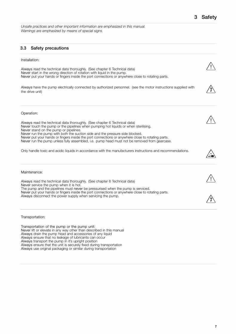
3.3 Safety precautions
Installation:
Always read the technical data thoroughly. (See chapter 6 Technical data) !Never start in the wrong direction of rotation with liquid in the pump.Never put your hands or fingers inside the port connections or anywhere close to rotating parts.
Always have the pump electrically connected by authorized personnel. (see the motor instructions supplied withthe drive unit)
Operation:
Always read the technical data thoroughly. (See chapter 6 Technical data) !Never touch the pump or the pipelines when pumping hot liquids or when sterilising.Never stand on the pump or pipelines.Never run the pump with both the suction side and the pressure side blocked.Never put your hands or fingers inside the port connections or anywhere close to rotating parts.Never run the pump unless fully assembled, i.e. pump head must not be removed from gearcase.
Only handle toxic and acidic liquids in accordance with the manufacturers instructions and recommendations.
Maintenance:
Always read the technical data thoroughly. (See chapter 6 Technical data) !Never service the pump when it is hot.The pump and the pipelines must never be pressurised when the pump is serviced.Never put your hands or fingers inside the port connections or anywhere close to rotating parts.Always disconnect the power supply when servicing the pump.
Transportation:
Transportation of the pump or the pump unit:Never lift or elevate in any way other than described in this manualAlways drain the pump head and accessories of any liquidAlways ensure that no leakage of lubricants can occurAlways transport the pump in it’s upright positionAlways ensure that the unit is securely fixed during transportationAlways use original packaging or similar during transportation
7
4 Installation
4.1 Unpacking, handling and storage
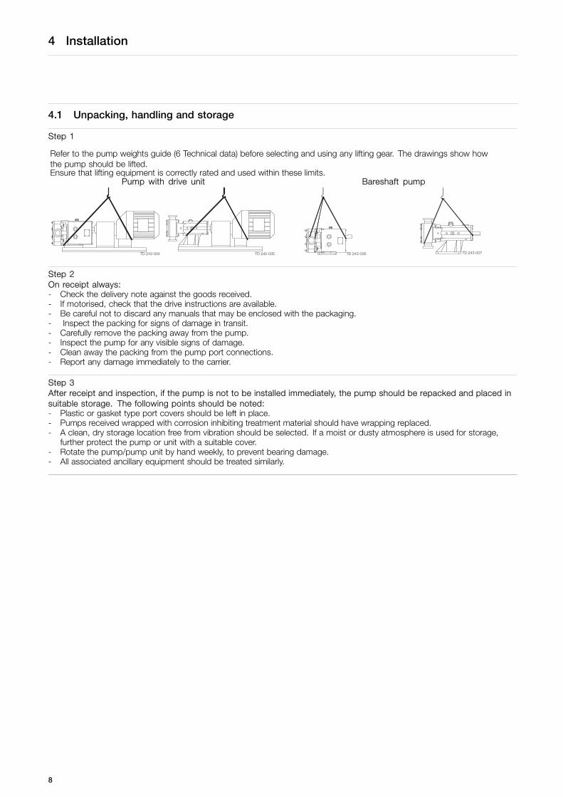
Step 1
Refer to the pump weights guide (6 Technical data) before selecting and using any lifting gear. The drawings show howthe pump should be lifted.Ensure that lifting equipment is correctly rated and used within these limits.
Pump with drive unit Bareshaft pump
Step 2On receipt always:- Check the delivery note against the goods received.- If motorised, check that the drive instructions are available.- Be careful not to discard any manuals that may be enclosed with the packaging.- Inspect the packing for signs of damage in transit.- Carefully remove the packing away from the pump.- Inspect the pump for any visible signs of damage.- Clean away the packing from the pump port connections.- Report any damage immediately to the carrier.
Step 3After receipt and inspection, if the pump is not to be installed immediately, the pump should be repacked and placed insuitable storage. The following points should be noted:- Plastic or gasket type port covers should be left in place.- Pumps received wrapped with corrosion inhibiting treatment material should have wrapping replaced.- A clean, dry storage location free from vibration should be selected. If a moist or dusty atmosphere is used for storage,
further protect the pump or unit with a suitable cover.- Rotate the pump/pump unit by hand weekly, to prevent bearing damage.- All associated ancillary equipment should be treated similarly.
8

4 Installation
To ensure optimum operation it is important that any pump unit is installed correctly. When designing a pumping system thefollowing should be taken into consideration.
4.2 System design and installation
Design: Discharge line
Plan view Suction line
Manifold suction/Common Line
- Confirm the Net Positive Suction Head (NPSH) availablefrom the system exceeds the NPSH required by the pump,as this is crucial for ensuring the smooth operation of thepump and preventing cavitation.
- Avoid suction lifts and manifold/common suction lines fortwo pumps running in parallel, as this may cause vibrationor cavitation.
- Protect the pump against blockage from hard solid objectse.g. nuts, bolts welding slag etc. Also protect the pumpfrom accidental operation against a closed valve by usingrelief valves, pressure switches or current limiting devices.
- Fit suction and discharge monitor points for diagnosticpurposes.
- Fit valves, if two pumps are to be used on manifold/commondischarge lines.
- Make the necessary piping arrangements if flushing isrequired for the seal or if a media is required for heating/cooling jackets and saddles.
- Allow at least 1 m for pump access/maintenance all aroundthe pump.
- Do not subject rotary lobe pumps to rapid temperaturechanges, as pump seizure can result from thermal shock.
Pipework:All pipework must be supported. The pump must not be allowed to support any of the pipework weight beyond the limitsset as shown in the following table.
Remember:Pipework supports must also support the weight of the productbeing pumped.- Design short straight suction lines to reduce friction losses
in the pipework thereby improving the NPSH available fromthe system.
- Avoid bends, tees and any restrictions close to eithersuction or discharge side of pump. Use long radius bendswherever possible.
- Provide isolating valves on each side of the pump whennecessary.
- Keep pipework horizontal where applicable to reduce airlocks. Include eccentric reducers on suction lines.
TD 243-089
X
Y
Z
9

4 Installation
To ensure optimum operation it is important that any pump unit is installed correctly. When designing a pumping system thefollowing should be taken into consideration.
Table of Maximum Forces and Moments
Forces MomentsPumpModel Units FZ FY FX EF Units MZ MY MX EM
N 80 60 70 120 Nm 75 90 115 165SRU1
lbf 18 13 16 27 lbft 55 66 85 122
N 125 100 110 195 Nm 90 105 130 190SRU2
lbf 28 22 25 44 lbft 66 77 96 140
N 165 135 150 260 Nm 100 115 140 205SRU3/4
lbf 37 30 34 58 lbft 74 85 103 151
N 300 250 250 460 Nm 125 145 175 260SRU5/6
lbf 67 56 56 103 lbft 92 107 129 192
Direction of flow:
The direction of flow is dictated by the direction of rotation of the drive shaft. Reversing the direction of rotation will reverse theflow direction.
Suction Discharge
Discharge Suction
Discharge Suction
Suction Discharge
10
4 Installation
To ensure optimum operation it is important that any pump unit is installed correctly. When designing a pumping system thefollowing should be taken into consideration.
Pump Lubrication:The pump will not be supplied pre-filled with oil therefore this table must be used to select recommended oil.Oil changing: Oil level must be checked with the pump static.First change: After 150 hours of operation, thereafter every 3000 hours of operation.Oil filling: Fill with oil through the filler plug to the level indicated in the sight glass.
NOTE!On horizontally ported pumps the sight glass must be fitted to the upper hole on the side of the gearcase. Refer to 6 Technicaldatafor oil approximate quantities required
Recommended OilsPump Operating Temperature Food grade oils (USDA H1)
-20°C to +130°C +130°C to 200°C -20°C to +130°C(-4°F to +266°F ) (+266°F to 392°F) (-4°F to +266°F)BP Energol GR - XP150 BP Enersyn SG-XP150 Bel-Ray No-Tox HD Food Grade Oil 150 #62686Castrol Alpha SP150 Castrol Alphasyn PG150 Mobil SHC Cibus 150Mobil Mobilgear 600 XP150 Mobil Glygoyle 30 Castrol Optileb GT150Shell Omala S2 G150 Shell Omala S4 WE150Texaco Meropa 150 Texaco Synlube CLP220Esso Spartan EP150 Mobil Glygoyle 22
For ATEX applications refer to ATEX addendum manual.
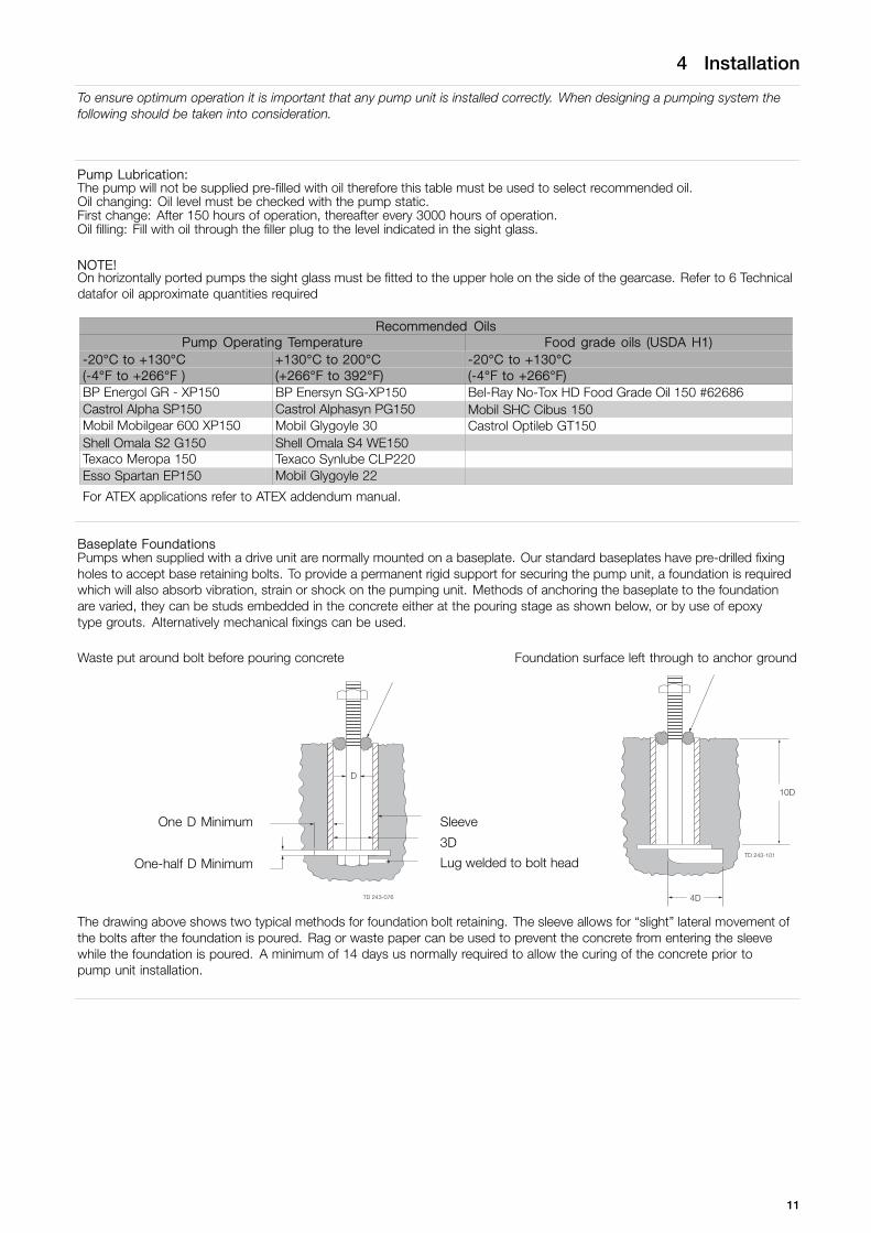
Baseplate FoundationsPumps when supplied with a drive unit are normally mounted on a baseplate. Our standard baseplates have pre-drilled fixingholes to accept base retaining bolts. To provide a permanent rigid support for securing the pump unit, a foundation is requiredwhich will also absorb vibration, strain or shock on the pumping unit. Methods of anchoring the baseplate to the foundationare varied, they can be studs embedded in the concrete either at the pouring stage as shown below, or by use of epoxytype grouts. Alternatively mechanical fixings can be used.
Waste put around bolt before pouring concrete Foundation surface left through to anchor ground
One D Minimum Sleeve
3D
One-half D Minimum Lug welded to bolt head
D
4D
10D
TD 243-101
The drawing above shows two typical methods for foundation bolt retaining. The sleeve allows for “slight” lateral movement ofthe bolts after the foundation is poured. Rag or waste paper can be used to prevent the concrete from entering the sleevewhile the foundation is poured. A minimum of 14 days us normally required to allow the curing of the concrete prior topump unit installation.
11

4 Installation
To ensure optimum operation it is important that any pump unit is installed correctly. When designing a pumping system thefollowing should be taken into consideration.
Coupling alignment:Before the pump unit is installed is it important to ensure that the mounting surface is flat to avoid distortion of the baseplate,which may cause pump/motor shaft misalignment and pump/motor unit damage. Once the baseplate has been secured, thepump shaft to motor shaft coupling alignment should be checked and adjusted as necessary. This is achieved by checkingthe maximum angular and parallel misalignment for the couplings as stated below. Shaft alignment that is outside the statedtolerances can be corrected by applying shims under the motor or pump foot, or, by moving the pump or drive sideways onthe baseplate. All bolts that have been loosened should be re-tightened to the stated torque figure.The following dimensions and tolerances apply to standard supply couplings only.
Parallel misalignmentMeasure 4 positions at 90° around coupling
Coupling size Dimension A Maximum70 0.3 mm90 0.3 mm
110 0.3 mm130 0.4 mm150 0.4 mm180 0.4 mm230 0.5 mm280 0.5 mmTD 246-090
A
Angular misalignmentMeasure 4 positions at 90° around coupling
Coupling size Dimension B Maximum70 1°90 1°
110 1°130 1°150 1°180 1°230 1°280 1°
TD 246-089
Bo
Assembled length
Coupling size Dimension L ± 1.0mm70 2590 30.5
110 45130 53150 60180 73230 85.5280 105.5
TD 246-088
L
Recommended bolt torques.
Thread Diameter M6 M8 M10 M12 M16 M20 M24Torque (Nm) 6 15 30 50 120 250 200
12
4 Installation
This page is not applicable for ATEX applications.For ATEX application see ATEX addendum
4.3 Flushing seal arrangement and pre-start up checks
Step 1A flushed seal arrangement is fitted in order to cool or clean the seal area.It is important that:- The flush is correctly connected (see below).- A compatible flushing fluid is used and supplied at the correct pressure and flow rate (see Step 5).- The flush is turned on at the same time/prior to starting the pump, and turned off at the same time/after stopping the pump.
Step 2Connecting the flushThe following equipment is strongly recommended when using a flushing system:- Control valve and pressure gauge, to enable the correct flushing pressure to be obtained and monitored.- Isolation valve and check valve, so that the flush can be turned off, and to stop any unwanted substances flowing in
the wrong direction.- A method of visibly indicating flushing fluid flow.
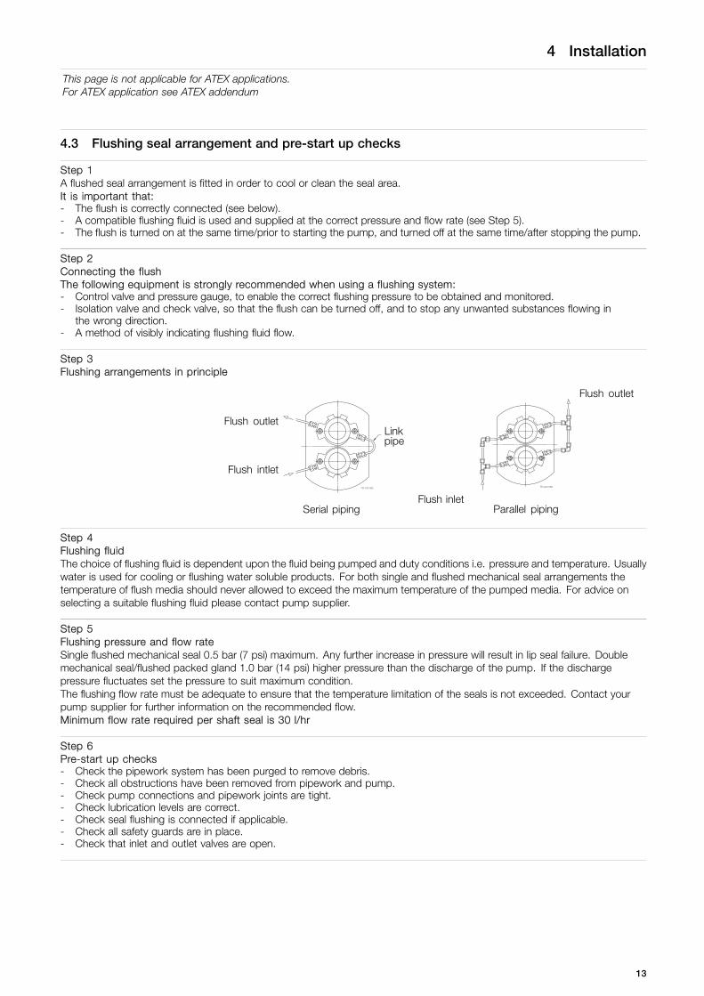
Step 3Flushing arrangements in principle
Flush outlet
Flush outletLinkpipe
Flush intlet
Flush inletSerial piping Parallel piping
Step 4Flushing fluidThe choice of flushing fluid is dependent upon the fluid being pumped and duty conditions i.e. pressure and temperature. Usuallywater is used for cooling or flushing water soluble products. For both single and flushed mechanical seal arrangements thetemperature of flush media should never allowed to exceed the maximum temperature of the pumped media. For advice onselecting a suitable flushing fluid please contact pump supplier.
Step 5Flushing pressure and flow rateSingle flushed mechanical seal 0.5 bar (7 psi) maximum. Any further increase in pressure will result in lip seal failure. Doublemechanical seal/flushed packed gland 1.0 bar (14 psi) higher pressure than the discharge of the pump. If the dischargepressure fluctuates set the pressure to suit maximum condition.The flushing flow rate must be adequate to ensure that the temperature limitation of the seals is not exceeded. Contact yourpump supplier for further information on the recommended flow.Minimum flow rate required per shaft seal is 30 l/hr
Step 6Pre-start up checks- Check the pipework system has been purged to remove debris.- Check all obstructions have been removed from pipework and pump.- Check pump connections and pipework joints are tight.- Check lubrication levels are correct.- Check seal flushing is connected if applicable.- Check all safety guards are in place.- Check that inlet and outlet valves are open.
13

4 Installation
4.4 Recycling information
Recycling information.• Unpacking
- Packing material consists of wood, plastics, cardboard boxes and in some cases metal straps.- Wood and cardboard boxes can be reused, recycled or used for energy recovery.- Plastics should be recycled or burnt at a licensed waste incineration plant.- Metal straps should be sent for material recycling.
• Maintenance
- During maintenance oil and wear parts in the machine are replaced.- All metal parts should be sent for material recycling.- Worn out or defective electronic parts should be sent to a licensed handler for material recycling.- Oil and all non metal wear parts must be taken care of in agreement with local regulations.
• Scrapping
- At end of use, the equipment shall be recycled according to relevant, local regulations. Beside the equipment itself, anyhazardous residues from the process liquid must be considered and dealt with in a proper manner. When in doubt, or in theabsence of local regulations, please contact the local Alfa Laval sales company.
14
5 Maintenance
5.1 Cleaning in place (CIP)
The pump can be manually cleaned or cleaned in place (CIP). The following is an example of a typical CIP procedure. Howeverspecific advice for each application should be sought from the pump supplier.
Typical CIP procedure1. Flush through the system with cold water or bore water (6°C) (43°F).2. Run hot caustic soda (70-80°C) (158-176°F) at 2.5% dilution through the system for 20-30 minutes.3. Final flush through with cold water again.
Warnings
Never touch the pump or the pipelines as they will be extremely hot!
Do not subject the pump to rapid temperature changes during CIP procedures, as pump seizurecan result from thermal shock.A suitable by-pass is recommended.
Always rinse well with clean water after using a cleaning agent.
Always use rubber gloves and protective goggles when handling caustic agent.
Always store/discharge cleaning agents in accordance with current rules/directives.
15

5 Maintenance
5.2 Maintenance schedule
It is advisable to install pressure gauges on both sides of the pump so that any problems within the pump/pipework canbe monitored.
Maintenance scheduleYour weekly schedule should include:- Checking the oil level in the gearcase with the pump stationary.- Checking the seals for leakage.- Checking the oil seals for leakage.- Check pumping pressures.
In certain operational circumstances the pump will pose a thermal hazard and as such should not be touched during operation.After shutdown the pump unit should be allowed time to cool.Oil should be changed every 3000 hours of operation or a period of 2 years, whichever is the soonest.
Recommended Spare Parts Part description QuantityLip seal drive end 1O-ring rotorcase cover 1Lip seal gland end 2O-ring rotor sealing shaft end 2O-ring rotor sealing nut end 2
The table shows recommended spare partsthat should be retained within your maintenanceschedule.
Primary seals 2
Rotor nut O-ring Seal Replacement IntervalIt is recommended that the rotor nut O-ring seal is replaced every 12 months to maintain a bacteria tight seal.
Rotor Nut Seal InspectionPeriodically inspect the rotor nut O-ring seal for any discoloration, nicks, or cracks. If any of the defects above are noticed,the O-ring seal must be replaced. Inspection and replacement refer to the seal replacement procedure below.
Seal Replacement Procedure1. Remove rotor case cover (see 5.3 Dismantling, step Step 1).2. Undo rotor nuts and ensure components are dry before servicing.3. With a penlight, inspect rotor nut blind tapped hole for contamination. If soiled, refer to cleaning procedure below.4. Remove and discard rotor nut O-ring seal.5. Fit new rotor nut O-ring seal.6. Fit rotor nut and use a torque wrench to tighten to correct torque value (see table 6.1.3 on page 37).7. Fit the rotor case cover.
Cleaning Procedure for Soiled Rotor Nut Tapped Hole1. Remove rotor nut from the shaft.2. Submerge and soak nut for 5 minutes in COP tank with 2% caustic wash.3. Scrub the hole with internal thread vigorously by plunging a clean sanitary bristle pipe brush in and out of the hole
for two minutes while submerged.4. Soak nut in acid sanitizer for 5 minutes, and then scrub the hole again with the pipe brush for two minutes.5. Rinse well with clean water and blow-dry blind tapped hole with clean air.6. Swab test the inside of the tapped hole to determine cleanliness.7. Should the swab test fail, repeat steps 2 thru 6 above until swab test is passed.Should swab testing continue to fail, or time is of the essence, install a new rotor nut.
16

5 Maintenance
5.3 Dismantling
Step 1Before dismantling the pump refer to safety precautions. Seeexploded view drawings (chapter 7 Parts list).Removing rotorcase cover1. Remove rotorcase cover nuts (13) and cover (12).
Step 2Removing rotors1. Insert a plastic/wooden block between the two rotors (17) to
stop them turning.2. Remove rotor retention nuts (22) and rotors. Pump series 6
rotors are retained by torque locking assemblies, TLA’s (19)and can be removed by:- Remove the rotor cap to reveal the TLA.- The screws now visible are unscrewed and the TLA is
removed.
Plastic or wooden block
Step 31. For packed gland seals loosen the gland followers to relieve the
packing pressure on the shaft.For flushed mechanical seal arrangements, remove the sealhousing retaining nuts and ease the seal housings from therotorcase.
2. Remove rotorcase retaining nuts (4) and washers (4A).3. Tap both sides of the rotorcase (9) with a soft mallet.4. Take care not to damage mechanical seals. The rotorcase
must not be allowed to drop onto the shafts (24 and 25) duringthe removal process.
5. Shims (8) should not be removed unless rotor clearancesrequire resetting.
Step 4Draining pump lubrication1. Place a tray under the gearcase to collect the waste lubricating
oil.2. Remove the lower drain plug (45) at the side of the gearcase (1).
17

5 Maintenance
Step 5Removing seal retainers1. Remove screws (15).2. Then remove seal retainers (14) - as a liquid sealant has been
used a lever may be required to remove retainers.3. The lip seals (16) can be removed using a screwdriver/ lever
once the seal retainers are removed. It is essential to renew thelip seals and it is recommended that new gaskets or sealantbe used prior to reassembly.
Step 6Removing Gearcase Cover1. Remove screws (6).2. Remove gearcase cover (5) after breaking the gasket seal then
press out the lip seal (7). It is essential to renew the lip sealprior to reassembly.
Step 7Removing timing gears1. Release clamp plate screws (40) and remove clamp plate (39)
on pump series 1,2 and 3. For pump series 4,5 and 6 removethe torque locking assembly screws in several stages.
2. Remove gears (36) using the tapped extraction holes provided,or remove shaft assembly as shown in step 8 below.
Step 8Shaft assembly removal1. Using a soft mallet gently tap the rear end of each shaft (24 and
25), to remove through the front of the gearcase (1).2. Support each shaft during removal from the gearcase.3. Remove the shaft abutment spacer (27).
- For vertically ported pumps this is placed in the right handbearing bore when viewed on the front face of the gear case.
- For horizontally ported pumps the shaft abutment spacer isplaced in the top bearing bore.
18
5 Maintenance
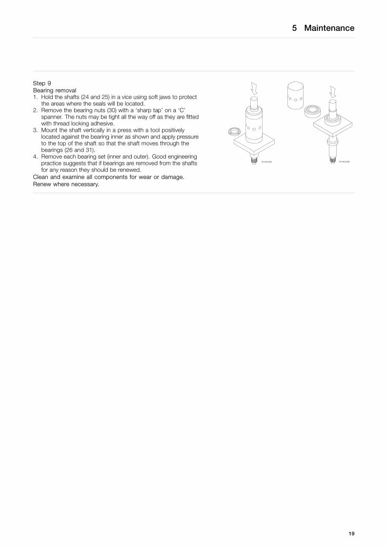
Step 9Bearing removal1. Hold the shafts (24 and 25) in a vice using soft jaws to protect
the areas where the seals will be located.2. Remove the bearing nuts (30) with a ‘sharp tap’ on a ‘C’
spanner. The nuts may be tight all the way off as they are fittedwith thread locking adhesive.
3. Mount the shaft vertically in a press with a tool positivelylocated against the bearing inner as shown and apply pressureto the top of the shaft so that the shaft moves through thebearings (26 and 31).
4. Remove each bearing set (inner and outer). Good engineeringpractice suggests that if bearings are removed from the shaftsfor any reason they should be renewed.
Clean and examine all components for wear or damage.Renew where necessary.
19
5 Maintenance
5.4 Assembly
5.4.1 Fitting bearings to shafts
Take care not to damage shaft surfaces, in particular where the seals will be located. Ensure all fastenings are tightened totorque settings as shown in 6 Technical data.
On series 1, 2 and 3 pumps, bearings do not require heating. For series 4, 5 and 6 pumps, heat the bearing inner cones to110°C (230°F).
Do not use any form of live flame when heating, as this will damage bearings.
Step 1Position shaft (24 and 25) vertically in a vice using soft jaws and apply anti-seize compound to the bearing diameters.
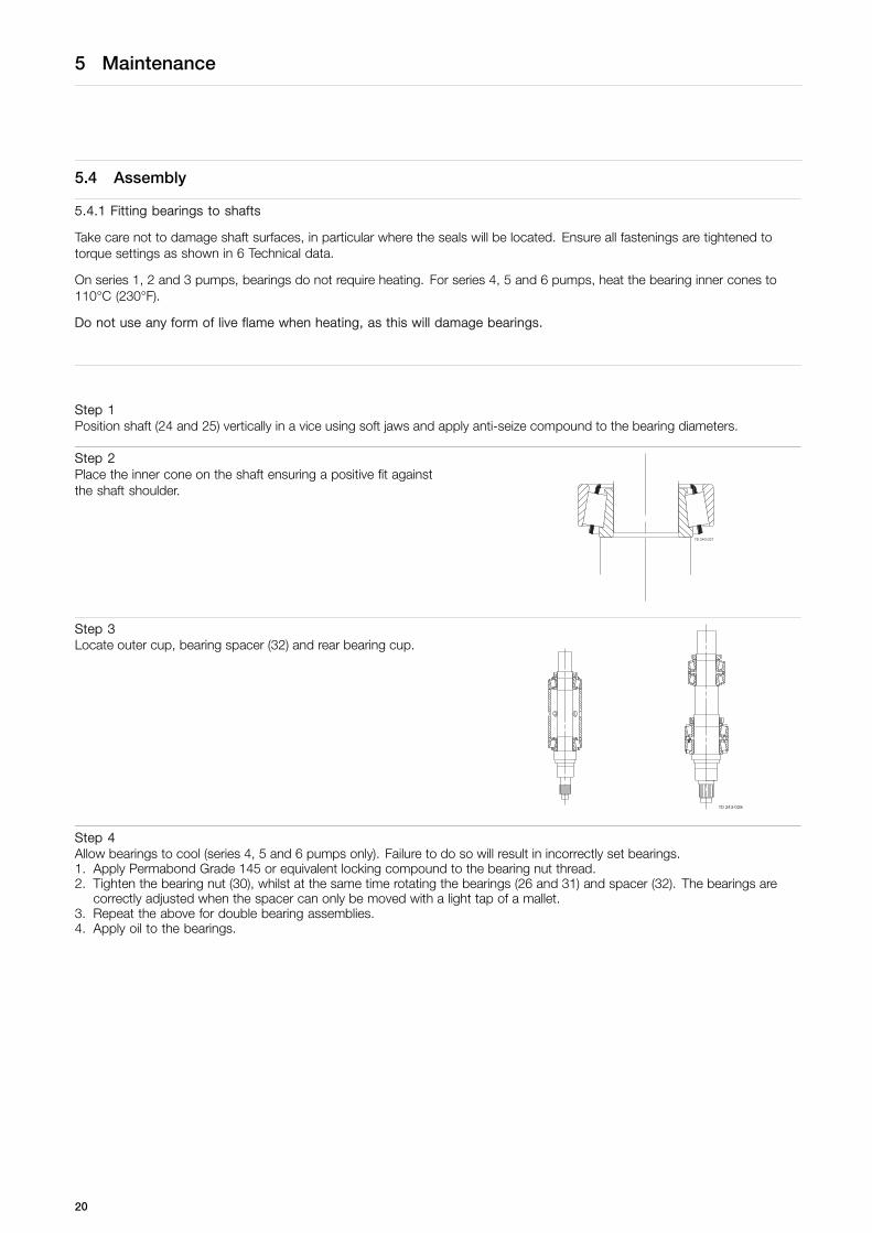
Step 2Place the inner cone on the shaft ensuring a positive fit againstthe shaft shoulder.
Step 3Locate outer cup, bearing spacer (32) and rear bearing cup.
Step 4Allow bearings to cool (series 4, 5 and 6 pumps only). Failure to do so will result in incorrectly set bearings.1. Apply Permabond Grade 145 or equivalent locking compound to the bearing nut thread.2. Tighten the bearing nut (30), whilst at the same time rotating the bearings (26 and 31) and spacer (32). The bearings are
correctly adjusted when the spacer can only be moved with a light tap of a mallet.3. Repeat the above for double bearing assemblies.4. Apply oil to the bearings.
20

5 Maintenance
5.4.2 Fitting Shaft Assemblies
Step 1Replace the shaft abutment spacer (27).- For vertically ported pumps this is placed in the right hand bearing bore when viewed on the front face of the gearcase.- For horizontally ported pumps the shaft abutment spacer is placed in the top bearing bore.
Step 2Identify drive and auxillary shaft positions according to gearcase cover (5) orientation.
Step 31. Using a soft faced mallet tap the shafts (24 and 25) into the
gearcase (1).2. If the bearings have been replaced, a new abutment spacer will
probably be needed. It is vital to ensure the rotor alignments iswithin the limits set in section 5.4.4.
5.4.3 Fitting seal retainers
Step 1Clean the rear face of the seal retainers (14), fit in position and tighten.
Step 21. Check rotor alignment is correct by reffering to the rotor abutment alignment in section 5.4.4.2. When rotor alignment is correct remove seal retainers and press new lip seals (16) into seal retainers. For temperatures
greater then 130oC (266oF) FPM lipseals are fitted.3. Apply liquid sealant onto the front of the gearcase (1) and push the seal retainers into position. Make sure lip seals are not
damaged when sliding them onto the shafts.
Step 3Replace and tighten the screws (15).
21

5 Maintenance
5.4.4 Checking rotor abutment alignment
Step 1Incorrect setting of rotor alignment will damage the pump.Fit rotors onto shafts (24 and 25) and tighten rotor retention nuts (22).
Step 21. Using a depth micrometer ensure axial alignment is within
tolerance of 0.012mm (0.0005 in).2. If the alignment is incorrect, the shaft abutment spacer (27)
must be replaced/machined.
5.4.5 Fitting timing gears
Step 1Slide timing gears (36) onto shafts (24 and 25), realigning timing marks.
Step 21. Before fitting the torque locking devices (38) lubricate them with
gear oil. Series 1, 2 and 3 high pressure pumps (i.e. LD andHD models) have two sets of elements.
2. Series 4, 5 and 6 pumps have torque locking assemblies.
Step 3Fit timing gear clamp plates (39) - series 1, 2 and 3 only.Fit torque locking assemblies (37) - series 4, 5 and 6 only.
Step 4Timing adjustment is now required:Tighten one clamp plate/torque locking assembly only, allowingrotation of the shaft in the other gear for timing adjustment. SeeAdjusting Rotor Timing section 5.4.6.
22
5 Maintenance
5.4.6 Adjusting rotor timing
Step 1If the rotor timing requires adjustment (and assuming the pump has not yet been re-built), it is important to establish thecause for the rotors mistiming before proceeding.To allow timing adjustment ensure that one shaft is able to rotate within the torque locking assembly/element. The other torquelocking assembly/element should be tightened to the recommended torque.
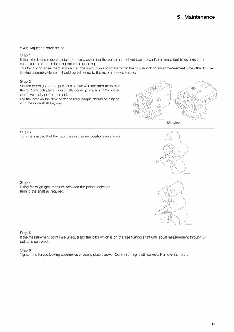
Step 2Set the rotors (17) to the positions shown with the rotor dimples inthe 6-12 o’clock plane (horizontally ported pumps) or 3-9 o’clockplane (vertically ported pumps).For the rotor on the drive shaft the rotor dimple should be alignedwith the drive shaft keyway.
Dimples
Step 3Turn the shaft so that the rotors are in the new positions as shown.
Step 4Using feeler gauges measure between the points indicated,turning the shaft as required.
Step 5If the measurement points are unequal tap the rotor which is on the free turning shaft until equal measurement through 6points is achieved.
Step 6Tighten the torque locking assemblies or clamp plate screws. Confirm timing is still correct. Remove the rotors.
23
5 Maintenance
5.4.7 Fitting gearcase cover
Step 1Clean the gearcase cover bore and remove all gasket material from the face. Press a new lip seal (7) into the cover (5). Fortemperatures greater than 130°C (266°F) FPM lip seals are fitted.
Step 2Apply liquid gasket to the face of the cover where it mates with the gearcase.
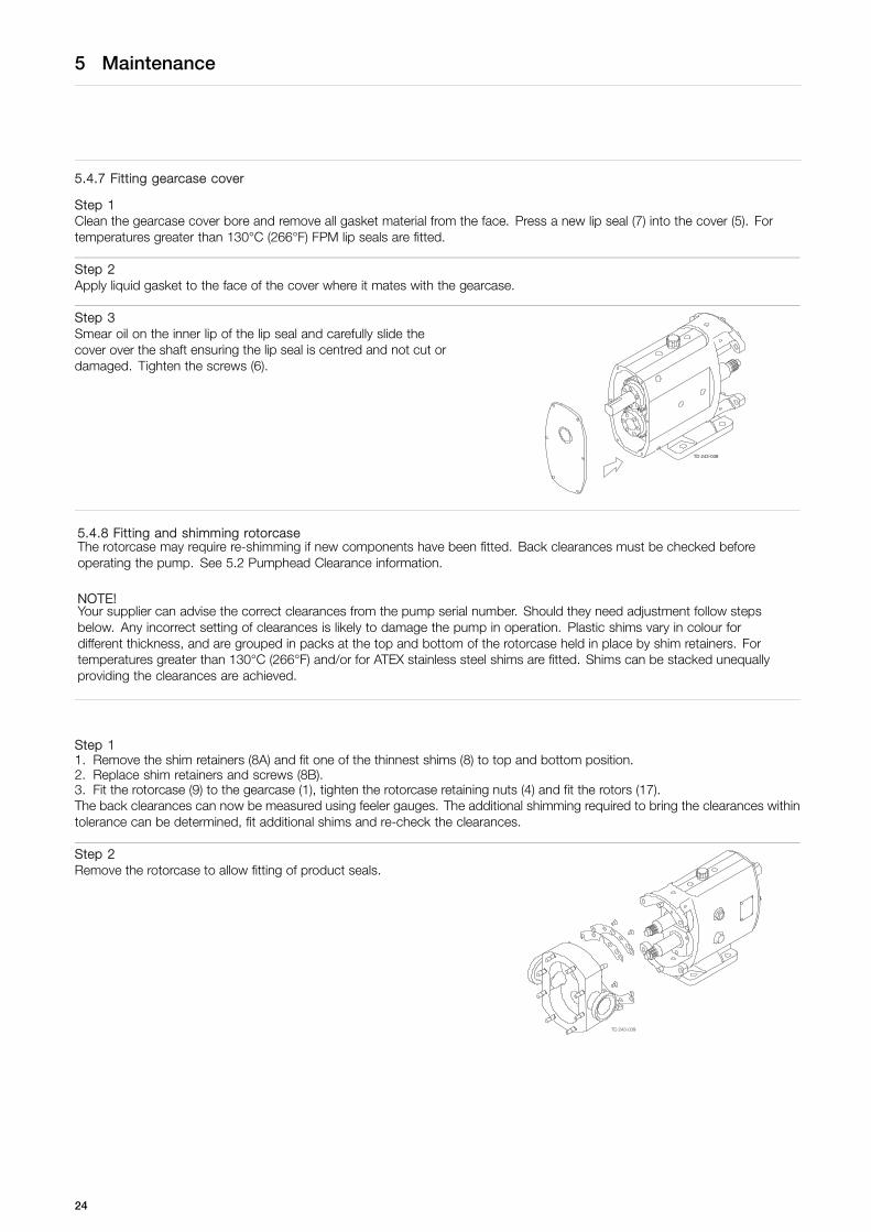
Step 3Smear oil on the inner lip of the lip seal and carefully slide thecover over the shaft ensuring the lip seal is centred and not cut ordamaged. Tighten the screws (6).
5.4.8 Fitting and shimming rotorcaseThe rotorcase may require re-shimming if new components have been fitted. Back clearances must be checked beforeoperating the pump. See 5.2 Pumphead Clearance information.
NOTE!Your supplier can advise the correct clearances from the pump serial number. Should they need adjustment follow stepsbelow. Any incorrect setting of clearances is likely to damage the pump in operation. Plastic shims vary in colour fordifferent thickness, and are grouped in packs at the top and bottom of the rotorcase held in place by shim retainers. Fortemperatures greater than 130°C (266°F) and/or for ATEX stainless steel shims are fitted. Shims can be stacked unequallyproviding the clearances are achieved.
Step 11. Remove the shim retainers (8A) and fit one of the thinnest shims (8) to top and bottom position.2. Replace shim retainers and screws (8B).3. Fit the rotorcase (9) to the gearcase (1), tighten the rotorcase retaining nuts (4) and fit the rotors (17).The back clearances can now be measured using feeler gauges. The additional shimming required to bring the clearances withintolerance can be determined, fit additional shims and re-check the clearances.
Step 2Remove the rotorcase to allow fitting of product seals.
24
5 Maintenance
5.4.9 Fitting primary seals
Step 1Refer to section 5.5 for seal fitting instructions.
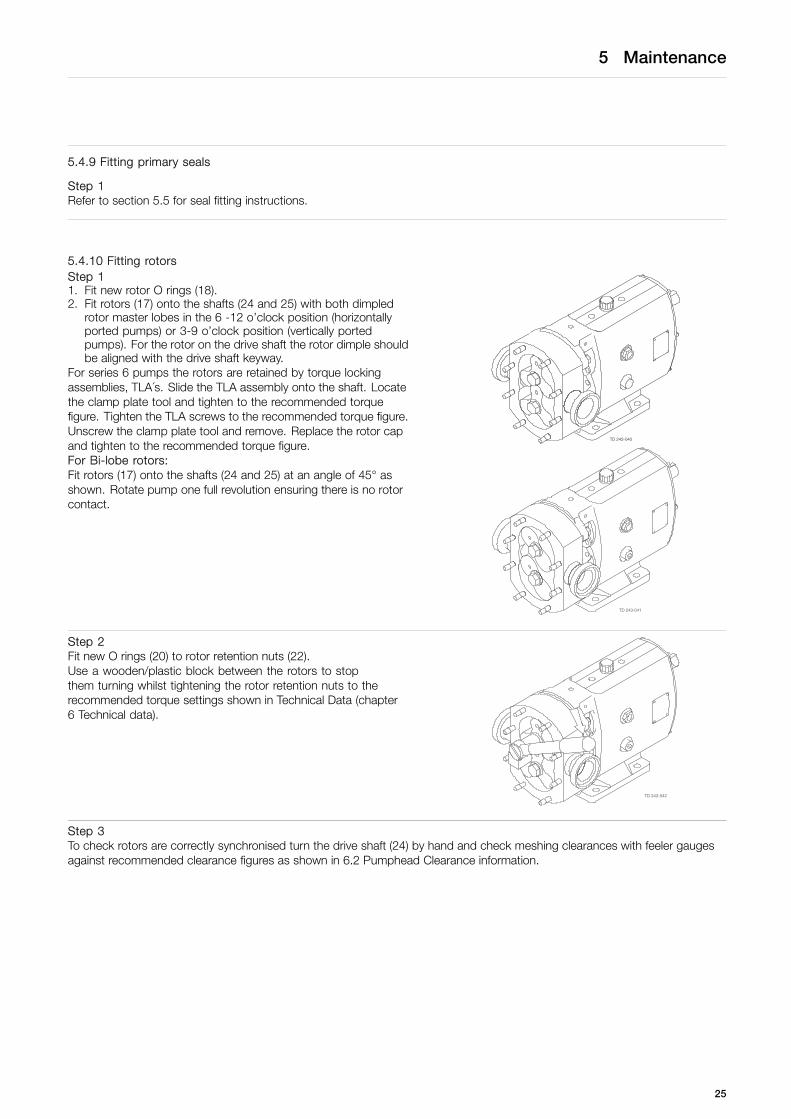
5.4.10 Fitting rotorsStep 11. Fit new rotor O rings (18).2. Fit rotors (17) onto the shafts (24 and 25) with both dimpled
rotor master lobes in the 6 -12 o’clock position (horizontallyported pumps) or 3-9 o’clock position (vertically portedpumps). For the rotor on the drive shaft the rotor dimple shouldbe aligned with the drive shaft keyway.
For series 6 pumps the rotors are retained by torque lockingassemblies, TLA´s. Slide the TLA assembly onto the shaft. Locatethe clamp plate tool and tighten to the recommended torquefigure. Tighten the TLA screws to the recommended torque figure.Unscrew the clamp plate tool and remove. Replace the rotor capand tighten to the recommended torque figure.For Bi-lobe rotors:Fit rotors (17) onto the shafts (24 and 25) at an angle of 45° asshown. Rotate pump one full revolution ensuring there is no rotorcontact.
Step 2Fit new O rings (20) to rotor retention nuts (22).Use a wooden/plastic block between the rotors to stopthem turning whilst tightening the rotor retention nuts to therecommended torque settings shown in Technical Data (chapter6 Technical data).
Step 3To check rotors are correctly synchronised turn the drive shaft (24) by hand and check meshing clearances with feeler gaugesagainst recommended clearance figures as shown in 6.2 Pumphead Clearance information.
25
5 Maintenance
5.4.11 Fitting rotorcase cover
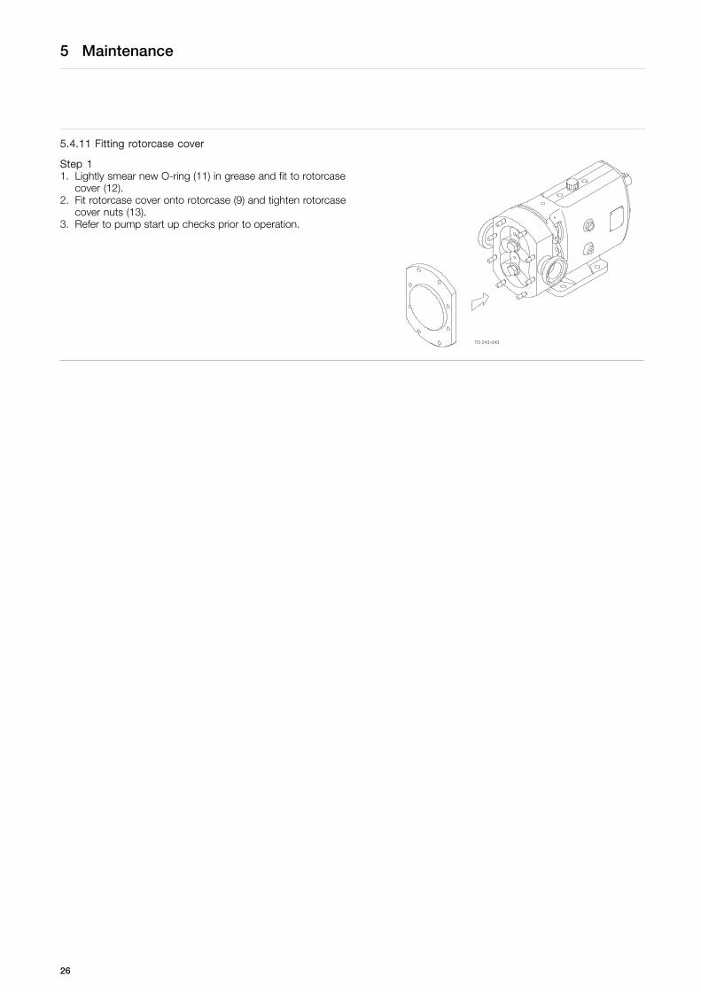
Step 11. Lightly smear new O-ring (11) in grease and fit to rotorcase
cover (12).2. Fit rotorcase cover onto rotorcase (9) and tighten rotorcase
cover nuts (13).3. Refer to pump start up checks prior to operation.
26
5 Maintenance
This page is not applicable for ATEX applications.For ATEX application see ATEX addendum
5.5 Primary seals removal and fitting
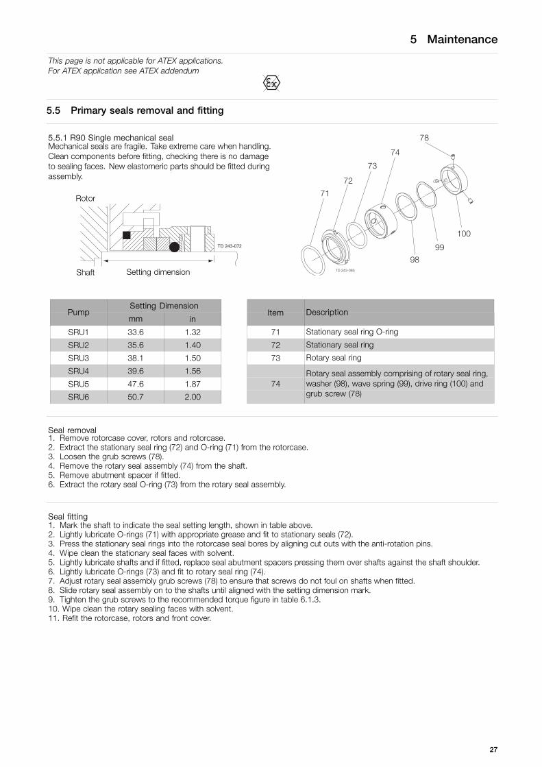
5.5.1 R90 Single mechanical sealMechanical seals are fragile. Take extreme care when handling.Clean components before fitting, checking there is no damageto sealing faces. New elastomeric parts should be fitted duringassembly.
Rotor
Shaft Setting dimension
Setting DimensionPump
mm inItem Description
SRU1 33.6 1.32 71 Stationary seal ring O-ring
SRU2 35.6 1.40 72 Stationary seal ring
SRU3 38.1 1.50 73 Rotary seal ring
SRU4 39.6 1.56
SRU5 47.6 1.87
SRU6 50.7 2.00
74Rotary seal assembly comprising of rotary seal ring,washer (98), wave spring (99), drive ring (100) andgrub screw (78)
Seal removal1. Remove rotorcase cover, rotors and rotorcase.2. Extract the stationary seal ring (72) and O-ring (71) from the rotorcase.3. Loosen the grub screws (78).4. Remove the rotary seal assembly (74) from the shaft.5. Remove abutment spacer if fitted.6. Extract the rotary seal O-ring (73) from the rotary seal assembly.
Seal fitting1. Mark the shaft to indicate the seal setting length, shown in table above.2. Lightly lubricate O-rings (71) with appropriate grease and fit to stationary seals (72).3. Press the stationary seal rings into the rotorcase seal bores by aligning cut outs with the anti-rotation pins.4. Wipe clean the stationary seal faces with solvent.5. Lightly lubricate shafts and if fitted, replace seal abutment spacers pressing them over shafts against the shaft shoulder.6. Lightly lubricate O-rings (73) and fit to rotary seal ring (74).7. Adjust rotary seal assembly grub screws (78) to ensure that screws do not foul on shafts when fitted.8. Slide rotary seal assembly on to the shafts until aligned with the setting dimension mark.9. Tighten the grub screws to the recommended torque figure in table 6.1.3.10. Wipe clean the rotary sealing faces with solvent.11. Refit the rotorcase, rotors and front cover.
27
5 Maintenance
This page is not applicable for ATEX applications.For ATEX application see ATEX addendum
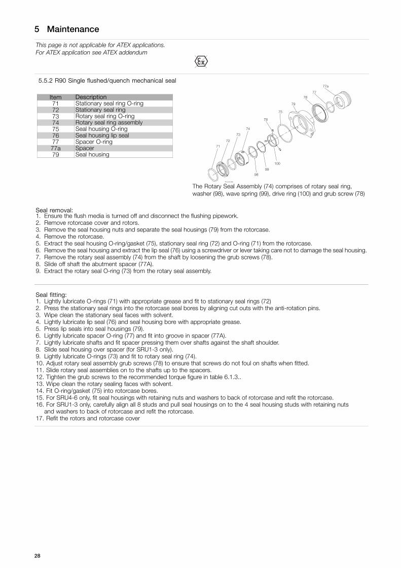
5.5.2 R90 Single flushed/quench mechanical seal
Item Description71 Stationary seal ring O-ring72 Stationary seal ring73 Rotary seal ring O-ring74 Rotary seal ring assembly75 Seal housing O-ring76 Seal housing lip seal77 Spacer O-ring77a Spacer79 Seal housing
The Rotary Seal Assembly (74) comprises of rotary seal ring,washer (98), wave spring (99), drive ring (100) and grub screw (78)
Seal removal:1. Ensure the flush media is turned off and disconnect the flushing pipework.2. Remove rotorcase cover and rotors.3. Remove the seal housing nuts and separate the seal housings (79) from the rotorcase.4. Remove the rotorcase.5. Extract the seal housing O-ring/gasket (75), stationary seal ring (72) and O-ring (71) from the rotorcase.6. Remove the seal housing and extract the lip seal (76) using a screwdriver or lever taking care not to damage the seal housing.7. Remove the rotary seal assembly (74) from the shaft by loosening the grub screws (78).8. Slide off shaft the abutment spacer (77A).9. Extract the rotary seal O-ring (73) from the rotary seal assembly.
Seal fitting:1. Lightly lubricate O-rings (71) with appropriate grease and fit to stationary seal rings (72)2. Press the stationary seal rings into the rotorcase seal bores by aligning cut outs with the anti-rotation pins.3. Wipe clean the stationary seal faces with solvent.4. Lightly lubricate lip seal (76) and seal housing bore with appropriate grease.5. Press lip seals into seal housings (79).6. Lightly lubricate spacer O-ring (77) and fit into groove in spacer (77A).7. Lightly lubricate shafts and fit spacer pressing them over shafts against the shaft shoulder.8. Slide seal housing over spacer (for SRU1-3 only).9. Lightly lubricate O-rings (73) and fit to rotary seal ring (74).10. Adjust rotary seal assembly grub screws (78) to ensure that screws do not foul on shafts when fitted.11. Slide rotary seal assemblies on to the shafts up to the spacers.12. Tighten the grub screws to the recommended torque figure in table 6.1.3..13. Wipe clean the rotary sealing faces with solvent.14. Fit O-ring/gasket (75) into rotorcase bores.15. For SRU4-6 only, fit seal housings with retaining nuts and washers to back of rotorcase and refit the rotorcase.16. For SRU1-3 only, carefully align all 8 studs and pull seal housings on to the 4 seal housing studs with retaining nuts
and washers to back of rotorcase and refit the rotorcase.17. Refit the rotors and rotorcase cover
28

5 Maintenance
This page is not applicable for ATEX applications.For ATEX application see ATEX addendum
5.5.3 R90 Double flushed mechanical seal
Item Description71 Stationary seal ring O-ring72 Stationary seal ring73 Rotary seal ring O-ring74a Rotary seal ring assembly - inboard74b Rotary seal ring assembly - outboard75 Seal housing O-ring79 Seal housing
The Rotary Seal Assembly Inboard (74A) comprises of rotary seal ring,washer (98), wave spring (99) and drive ring (100). The Rotary SealAssembly Outboard (74B) comprises of rotary seal ring, grub screw(78), washer (98) and wave spring (99).
Seal removal:1. Ensure the flush media is turned off and disconnect the flushing pipework.2. Remove rotorcase cover and rotors.3. Turn the drive shaft until the drive ring grub screws (78) are visible through the flushing connections.4. Loosen the grub screws.5. Remove the rotorcase.6. Remove seal housings (79) complete with rotary seal assemblies (74A and 74B) and outboard stationary seals.7. Extract the seal housing O-ring (75), stationary seal ring (72) and ‘o’ ring (71) from the rotorcase.
Seal fitting:Ensure seal orientation is correct. Outboard
Inboard
Series 1, the outboard seal fits over theinboard seal.
Inboard
Outboard
Series 2-6, the inboard seal fits over theoutboard seal.
1. Lightly lubricate O-rings (71 and 73) with appropriate grease and fit to rotary seal assemblies and stationary seal rings(74A, 74B and 72).
2. Fit stationary seals into the rotorcase bores and seal housings (79).3. Fit O-ring (75) into the rotorcase bores.4. Wipe clean the sealing faces with solvent.5. Locate rotary seal assemblies and fit the seal housings to the rotorcase ensuring that the grub screws (78) are accessible
so they can be tightened.6. Refit the rotorcase.7. Turn the drive shaft until the grub screws are visible through the flushing connections.8. Tighten the grub screws to the recommended torque figure in .9. Refit the rotors and rotorcase cover.
29

5 Maintenance
This page is not applicable for ATEX applications.For ATEX application see ATEX addendum
5.5.4 Hyclean single mechanical seal
Item Description81 Rotorcase O-ring82 Wave spring83 Stationary seal ring84 Shaft O-ring85 Rotary seal ring86 Washer89 Clip
81
82
83
9089 84
85
86
3201-0002
Seal removal:1. Remove rotorcase cover, rotors and rotorcase.2. Undo screws and remove clips (89) and washers (90) from the rotorcase.3. Remove the stationary seal rings (83), wave springs (84) and rotorcase O-rings (81) from the rotorcase.4. Remove the rotary seal rings (85) and rubber washers (86) from the shafts.5. Remove the shaft O-rings (84) from the shafts.
Seal fitting:1. Lightly lubricate shaft O-rings (84) with appropriate grease and fit to shafts.2. Lightly lubricate both sides of rubber washer (86) and fit to rotary seal rings (85) ensuring location under the drive pin.3. Slide the rotary seal rings on to the shafts lining up pins to slots on the shafts.4. Lightly lubricate rotorcase O-rings (81) with appropriate grease and fit to rotorcase.5. Fit wave springs (82) into the rotorcase seal bores.6. Press the stationary seal rings (83) into the rotorcase, lining up slots.7. Replace clips (89) and washers (90) by tightening screws.
Note: For SRU1-5 pump models the washer is placed underneath the clip but for SRU6 pump models the washer isplaced on top of the clip.
8. Wipe clean the sealing faces with solvent.9. Refit the rotorcase, rotors and rotorcase cover.
30
5 Maintenance
This page is not applicable for ATEX applications.For ATEX application see ATEX addendum
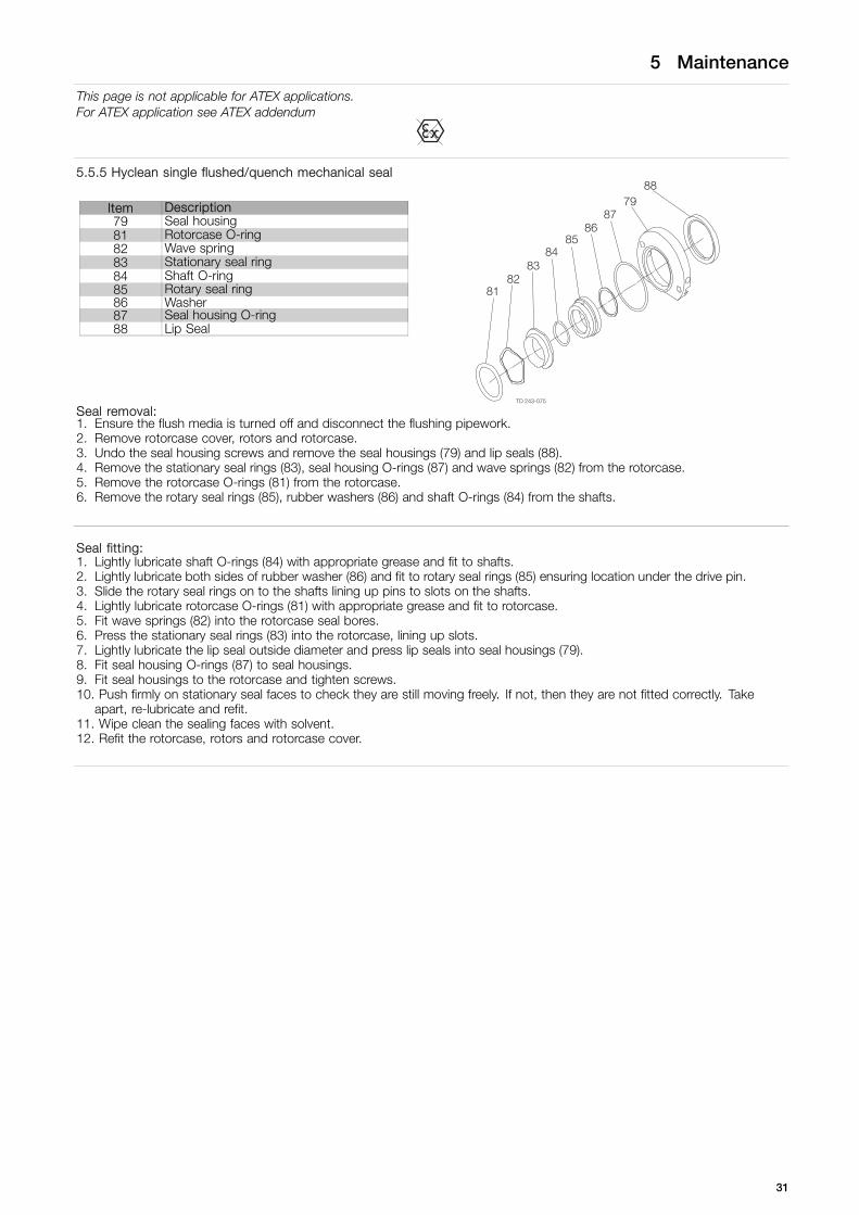
5.5.5 Hyclean single flushed/quench mechanical seal
Item Description79 Seal housing81 Rotorcase O-ring82 Wave spring83 Stationary seal ring84 Shaft O-ring85 Rotary seal ring86 Washer87 Seal housing O-ring88 Lip Seal
Seal removal:1. Ensure the flush media is turned off and disconnect the flushing pipework.2. Remove rotorcase cover, rotors and rotorcase.3. Undo the seal housing screws and remove the seal housings (79) and lip seals (88).4. Remove the stationary seal rings (83), seal housing O-rings (87) and wave springs (82) from the rotorcase.5. Remove the rotorcase O-rings (81) from the rotorcase.6. Remove the rotary seal rings (85), rubber washers (86) and shaft O-rings (84) from the shafts.
Seal fitting:1. Lightly lubricate shaft O-rings (84) with appropriate grease and fit to shafts.2. Lightly lubricate both sides of rubber washer (86) and fit to rotary seal rings (85) ensuring location under the drive pin.3. Slide the rotary seal rings on to the shafts lining up pins to slots on the shafts.4. Lightly lubricate rotorcase O-rings (81) with appropriate grease and fit to rotorcase.5. Fit wave springs (82) into the rotorcase seal bores.6. Press the stationary seal rings (83) into the rotorcase, lining up slots.7. Lightly lubricate the lip seal outside diameter and press lip seals into seal housings (79).8. Fit seal housing O-rings (87) to seal housings.9. Fit seal housings to the rotorcase and tighten screws.10. Push firmly on stationary seal faces to check they are still moving freely. If not, then they are not fitted correctly. Take
apart, re-lubricate and refit.11. Wipe clean the sealing faces with solvent.12. Refit the rotorcase, rotors and rotorcase cover.
31
5 Maintenance
This page is not applicable for ATEX applications.For ATEX application see ATEX addendum
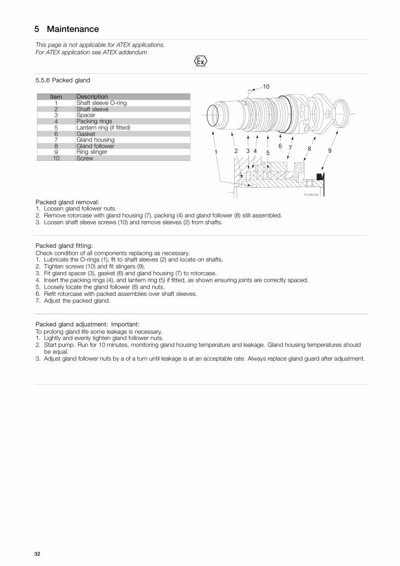
5.5.6 Packed gland
Item Description1 Shaft sleeve O-ring2 Shaft sleeve3 Spacer4 Packing rings5 Lantern ring (if fitted)6 Gasket7 Gland housing8 Gland follower9 Ring slinger10 Screw
Packed gland removal:1. Loosen gland follower nuts.2. Remove rotorcase with gland housing (7), packing (4) and gland follower (8) still assembled.3. Loosen shaft sleeve screws (10) and remove sleeves (2) from shafts.
Packed gland fitting:Check condition of all components replacing as necessary.1. Lubricate the O-rings (1), fit to shaft sleeves (2) and locate on shafts.2. Tighten screws (10) and fit slingers (9).3. Fit gland spacer (3), gasket (6) and gland housing (7) to rotorcase.4. Insert the packing rings (4), and lantern ring (5) if fitted, as shown ensuring joints are correctly spaced.5. Loosely locate the gland follower (8) and nuts.6. Refit rotorcase with packed assemblies over shaft sleeves.7. Adjust the packed gland.
Packed gland adjustment: Important:To prolong gland life some leakage is necessary.1. Lightly and evenly tighten gland follower nuts.2. Start pump. Run for 10 minutes, monitoring gland housing temperature and leakage. Gland housing temperatures should
be equal.3. Adjust gland follower nuts by a of a turn until leakage is at an acceptable rate. Always replace gland guard after adjustment.
32
5 Maintenance
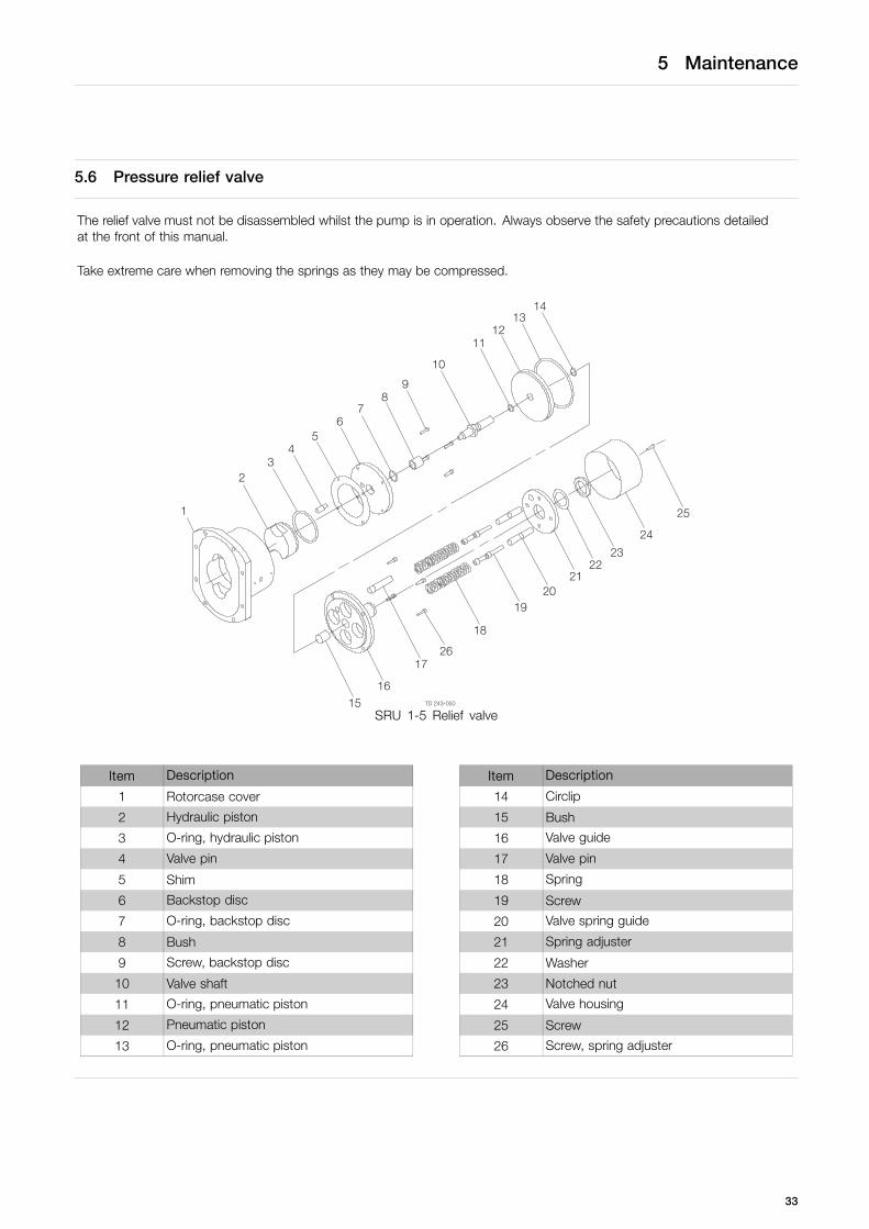
5.6 Pressure relief valve
The relief valve must not be disassembled whilst the pump is in operation. Always observe the safety precautions detailedat the front of this manual.
Take extreme care when removing the springs as they may be compressed.
SRU 1-5 Relief valve
Item Description Item Description
1 Rotorcase cover 14 Circlip
2 Hydraulic piston 15 Bush
3 O-ring, hydraulic piston 16 Valve guide
4 Valve pin 17 Valve pin
5 Shim 18 Spring
6 Backstop disc 19 Screw
7 O-ring, backstop disc 20 Valve spring guide
8 Bush 21 Spring adjuster
9 Screw, backstop disc 22 Washer
10 Valve shaft 23 Notched nut
11 O-ring, pneumatic piston 24 Valve housing
12 Pneumatic piston 25 Screw
13 O-ring, pneumatic piston 26 Screw, spring adjuster
33

5 Maintenance
5.6.1 Relief Valve Disassembly1. Remove manual override lever if fitted.2. Remove screws (25) and valve housing (24).3. Remove notched nut(s) (23) and spring adjuster (21). If springs are still compressed when the notched nut reaches end of
thread, release the spring adjuster screws (26).4. Remove springs (18) (series 1-5), spring stacks (series 6), screws and valve guide (16).5. Remove circlip (14) and pneumatic piston (12).6. Remove screws, backstop disc (6) and hydraulic piston (2)7. Unscrew hydraulic piston (2) from valve shaft (10) and remove O-rings (3, 7, 11 and 13).
5.6.2 Relief Valve AssemblyNew O-rings should be fitted during assembly. Clean components before fitting; check there is no damage to faces.1. Lubricate all O-rings.2. Fit O-ring (7) to backstop disc (6) and fit backstop disc to valve shaft (10)3. Fit O-ring (3) to hydraulic piston (2) and screw onto valve shaft.4. Locate assembly into rotorcase cover, replace backstop disc screws (9).5. Fit pneumatic piston O-rings (11 and 13) and locate assembly on valve shaft. Replace circlip (14) and springs (18). (Series 6
pumps only - each spring stack should contain an equal amount of springs, noting correct orientation). Place valve guide(16) over springs and replace screws (26).
6. Fit spring adjuster (21) and notched nut (23), valve housing (24) and screw (25).7. Replace manual override lever if applicable.
5.6.3 Valve AdjustmentThe relief valve will require setting to suit duty requirements.Note: A gauge is required to measure discharge pressureduring adjustment Thin rod1. Stop the pump2. Remove valve housing (24).3. Release notched nut(s) (23) to end of thread.4. Insert a thin rod into valve guide (16) and mark to indicate
closed position.5. Start pump and increase pressure noting pressure gauge
reading when the rod starts to move. This indicates thevalve is beginning to open.
6. Tighten the notched nut gradually until desired systempressure is achieved. (Series 6 pump only - evenly tightenthe spring stack nuts after adjusting the notched nut).
7. Apply thread locking adhesive to the notched nut after reliefvalve is set.
8. If pneumatic override is required connect air supply andadjust pressure until valve opens. Check piston reseatswhen air supply is disconnected.
9. Replace valve housing and screws.
34

5 Maintenance
5.7 Heating/Cooling devices
The SRU pumps have the option of being fitted with heating/cooling devices.These are primarily used for heating the pumphead so as to maintain the pumped media viscosity and reduce risk of anycrystallisation/solidification.They may also be used for cooling purposes.
Saddle
ConnectionsScrew for steam,
hot/cold fluid
Jacket
TD 243-087
Jackets can be fitted to the rotorcase cover and/or saddles can be fitted to the rotorcase.
The maximum pressure and temperature of heating/cooling fluid is 3.5 bar (50 psi) and 150°C (302°F) respectively.Heating/cooling jackets and saddles should be in operation approximately 15 minutes prior to pump start up and remain inoperation 15 minutes after pump shut down.
Assembly1. Clean faces where sealant is to be applied2. Apply Loctite 5970 silicone sealant or equivalent to face of heating jacket/saddle allow to dry for approx. 5-10 minutes.3. Locate cap screws in jacket/saddle, and align screws with tapped holes in rotorcase/front cover and tighten evenly.4. Allow instant gasket to cure fully before operation
SRU1 SRU2 SRU3 SRU4 SRU5 SRU6
Screw
Saddle (size/torque) M4/2Nm M6/8 Nm M6/8 Nm M6/18 Nm M6/35 Nm M6/35 Nm
Jacket (size/torque) M8/8 Nm M8/8 Nm M10/8 Nm M8/18 Nm M10/18 Nm M8/18 Nm
Flush connection
Saddle (BSPT) 1/8” 1/4” 1/4” 1/4” 1/4” 1/4”
Jacket (BSPT) 1/4” 1/4” 1/4” 1/4” 1/4” 1/4”
All flush connections are Female
35

5 Maintenance
5.8 Troubleshooting
Problem
No
flo
w U
nder
cap
acity
Irre
gul
ar d
isch
arg
e L
ow
dis
char
ge
pre
ssur
e P
ump
will
no
t p
rim
e P
rim
e lo
st a
fter
sta
rtin
g P
ump
sta
lls w
hen
star
ting
Pum
p o
verh
eats
Mo
tor
ove
rhea
ts E
xces
sive
po
wer
ab
sorb
ed N
ois
e an
d v
ibra
tion
Pum
p e
lem
ent
wea
r S
ypho
ning
Sei
zure
Mec
hani
cal s
eal l
eaka
ge
Mec
hani
cal s
eal l
eaka
ge
Probable Causes Solutions
√ √ Incorrect direction of rotation. Reverse motor.
√ Pump not primed. Expel gas from suction line and pumping chamber and introduce fluid.Increase suction line diameter.Increase suction head.Simplify suction line configuration and reduce length.√ √ √ √ √ √ Insufficient NPSH available.
Reduce pump speed.Increase suction line diameter.Increase suction head.Simplify suction line configuration and reduce length.√ √ √ √ √ Fluid vaporising in suction line.
Reduce pump speed.
√ √ √ √ √ √ Air entering suction line. Remake pipework joints.
√ √ √ √ √ Strainer or filter blocked. Service fittings.Increase fluid temperature.Decrease pump speed.√ √ √ √ √ √ √ √ Fluid viscosity above rated figure.Check seal face viscosity limitations.Decrease fluid temperature.√ √ √ Fluid viscosity below rated figure.Increase pump speed.Cool the pump casing.Reduce fluid temperature.√ √ √ √ √ Fluid temp. above rated figure.Check seal face and elastomer temp. limitations.Heat the pump casing.√ √ √ Fluid temp. below rated figure.Increase fluid temperature.Clean the system.Fit strainer to suction line.√ √ √ √ Unexpected solids in fluid.If solids cannot be eliminated, consider fitting double mechanical seals.Check for obstructions i.e. closed valve.Service system and change to prevent problem recurring.√ √ √ √ √ √ √ √ √ √ √ √ √ Discharge pressure above rated figureSimplify discharge line to decrease pressure.
√ √ √ √ Gland over-tightened Slacken and re-adjust gland packing.
√ √ √ √ √ Gland under-tightened Adjust gland packing.Increase flush flow rate.√ √ Seal flushing inadequate.Check that flush fluid flows freely into seal area.
√ √ √ √ Pump speed above rated figure. Decrease pump speed.
√ √ Pump speed below rated figure. Increase pump speed.Check alignment of pipes.Fit flexible pipes or expansion fittings.√ √ √ √ √ √ √ Pump casing strained by pipework.Support pipework.
√ √ √ √ Flexible coupling misaligned. Check alignment and adjust mountings accordingly.
√ √ √ √ √ √ Insecure pump driver mountings. Fit lock washers to slack fasteners and re-tighten.
√ √ √ √ √ √ √ √ Shaft bearing wear or failure. Refer to pump maker for advice and replacement parts.
√ √ √ √ √ √ Insufficient gearcase lubrication. Refer to pump maker’s instructions.Check rated and duty pressures.√ √ √ √ √ √ √ √ Metal to metal contact of pumping element.Refer to pump maker.
√ √ √ Worn pumping element. Fit new components.Check pressure setting and re-adjust if necessary.Examine and clean seating surfaces.√ √ √ Rotorcase cover relief valve leakage.Replace worn parts.Check for wear on sealing surfaces, guides etc.√ √ Rotorcase cover relief valve - chatter.Replace if necessary.
√ √ Rotorcase cover relief valve incorrectly set. Re-adjust spring compression - valve should lift approx. 10% above duty pressure.
√ √ Suction lift too high. Lower pump or raise liquid level.Fluid pumped not compatible with√ √ materials used.
Use optional materials.
√ No barrier in system to prevent flow passing. Ensure discharge pipework higher than suction tank.Ensure system operation prevents this.Fit single or double flushed mechanical seals.√ √ Pump allowed to run dry.Fit flushed packed gland.
√ √ Faulty motor. Check and replace motor bearings.
√ Pumping element missing Fit pumping element.
36

6 Technical data
6.1 Technical data
6.1.1 Approximate oil capacitiesPump model Port orientation Port orientation
Vertical litres Horizontal litres Vertical US pints Horizontal US pintsSRU1 0.3 0.4 0.6 0.8SRU2 0.6 0.7 1.2 1.4SRU3 1.0 1.5 2.2 3.1SRU4 1.5 2.0 3.2 4.2SRU5 3.0 4.0 6.3 8.4SRU6 4.5 7.0 9.5 14.8
6.1.2 WeightsPump model Bare Shaft Pump kg (lb) Typical pump with drive unit kg (lb)
Port Orientation Port OrientationHorizontal Vertical Horizontal Vertical
SRU1/005 15 (33) 16 (35) 45 (99) 46 (101)SRU1/008 17 (37) 18 (40) 55 (121) 56 (123)SRU2/013 28 (62) 30 (66) 75 (165) 77 (170)SRU2/018 29 (64) 31 (68) 80 (176) 82 (181)SRU3/027 53 (117) 56 (123) 145 (320) 148 (326)SRU3/038 56 (123) 59 (130) 150 (331) 153 (337)SRU4/055 105 (231) 111 (245) 260 (573) 266 (586)SRU4/079 110 (243) 116 (256) 265 (584) 271 (597)SRU5/116 148 (326) 185 (408) 396 (873) 433 (955)SRU5/168 156 (344) 193 (425) 411 (906) 448 (988)SRU6/260 228 (503) 260 (573) 493 (1087) 525 (1157)SRU6/353 233 (514) 265 (584) 513 (1131) 545 (1202)
The above weights are for guidance purposes only and will vary dependent upon specification of pump, baseplate and drive unit.
37
6 Technical data
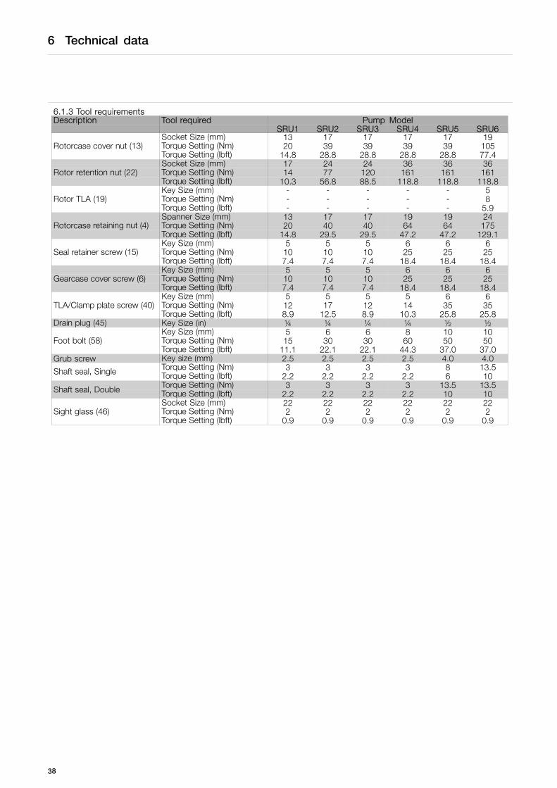
6.1.3 Tool requirementsDescription Tool required Pump Model
SRU1 SRU2 SRU3 SRU4 SRU5 SRU6Socket Size (mm) 13 17 17 17 17 19Torque Setting (Nm) 20 39 39 39 39 105Rotorcase cover nut (13)Torque Setting (lbft) 14.8 28.8 28.8 28.8 28.8 77.4Socket Size (mm) 17 24 24 36 36 36Torque Setting (Nm) 14 77 120 161 161 161Rotor retention nut (22)Torque Setting (lbft) 10.3 56.8 88.5 118.8 118.8 118.8Key Size (mm) - - - - - 5Torque Setting (Nm) - - - - - 8Rotor TLA (19)Torque Setting (lbft) - - - - - 5.9Spanner Size (mm) 13 17 17 19 19 24Torque Setting (Nm) 20 40 40 64 64 175Rotorcase retaining nut (4)Torque Setting (lbft) 14.8 29.5 29.5 47.2 47.2 129.1Key Size (mm) 5 5 5 6 6 6Torque Setting (Nm) 10 10 10 25 25 25Seal retainer screw (15)Torque Setting (lbft) 7.4 7.4 7.4 18.4 18.4 18.4Key Size (mm) 5 5 5 6 6 6Torque Setting (Nm) 10 10 10 25 25 25Gearcase cover screw (6)Torque Setting (lbft) 7.4 7.4 7.4 18.4 18.4 18.4Key Size (mm) 5 5 5 5 6 6Torque Setting (Nm) 12 17 12 14 35 35TLA/Clamp plate screw (40)Torque Setting (lbft) 8.9 12.5 8.9 10.3 25.8 25.8
Drain plug (45) Key Size (in) ¼ ¼ ¼ ¼ ½ ½Key Size (mm) 5 6 6 8 10 10Torque Setting (Nm) 15 30 30 60 50 50Foot bolt (58)Torque Setting (lbft) 11.1 22.1 22.1 44.3 37.0 37.0
Grub screw Key size (mm) 2.5 2.5 2.5 2.5 4.0 4.0Torque Setting (Nm) 3 3 3 3 8 13.5Shaft seal, Single Torque Setting (lbft) 2.2 2.2 2.2 2.2 6 10Torque Setting (Nm) 3 3 3 3 13.5 13.5Shaft seal, Double Torque Setting (lbft) 2.2 2.2 2.2 2.2 10 10Socket Size (mm) 22 22 22 22 22 22Torque Setting (Nm) 2 2 2 2 2 2Sight glass (46)Torque Setting (lbft) 0.9 0.9 0.9 0.9 0.9 0.9
38
6 Technical data
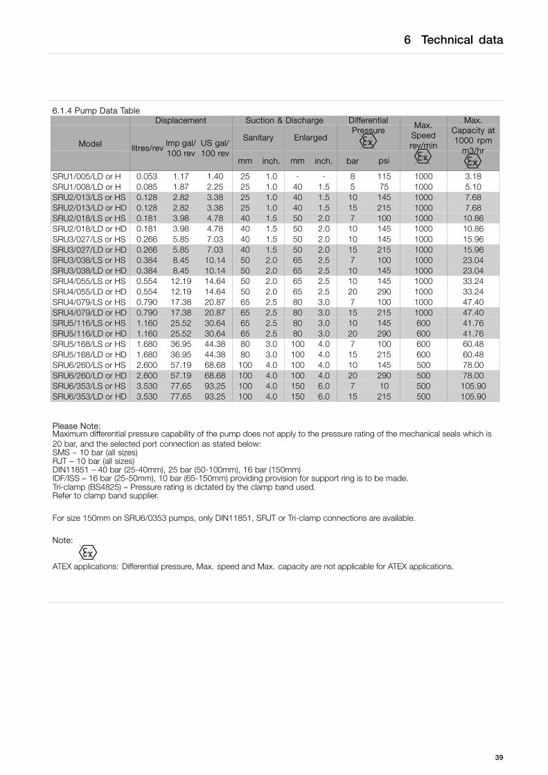
6.1.4 Pump Data TableDisplacement Suction & Discharge
Sanitary Enlarged
DifferentialPressure
Model litres/revImp gal/100 rev
US gal/100 rev
mm inch. mm inch. bar psi
Max.Speedrev/min
Max.Capacity at1000 rpm
m3/hr
SRU1/005/LD or H 0.053 1.17 1.40 25 1.0 - - 8 115 1000 3.18SRU1/008/LD or H 0.085 1.87 2.25 25 1.0 40 1.5 5 75 1000 5.10SRU2/013/LS or HS 0.128 2.82 3.38 25 1.0 40 1.5 10 145 1000 7.68SRU2/013/LD or HD 0.128 2.82 3.38 25 1.0 40 1.5 15 215 1000 7.68SRU2/018/LS or HS 0.181 3.98 4.78 40 1.5 50 2.0 7 100 1000 10.86SRU2/018/LD or HD 0.181 3.98 4.78 40 1.5 50 2.0 10 145 1000 10.86SRU3/027/LS or HS 0.266 5.85 7.03 40 1.5 50 2.0 10 145 1000 15.96SRU3/027/LD or HD 0.266 5.85 7.03 40 1.5 50 2.0 15 215 1000 15.96SRU3/038/LS or HS 0.384 8.45 10.14 50 2.0 65 2.5 7 100 1000 23.04SRU3/038/LD or HD 0.384 8.45 10.14 50 2.0 65 2.5 10 145 1000 23.04SRU4/055/LS or HS 0.554 12.19 14.64 50 2.0 65 2.5 10 145 1000 33.24SRU4/055/LD or HD 0.554 12.19 14.64 50 2.0 65 2.5 20 290 1000 33.24SRU4/079/LS or HS 0.790 17.38 20.87 65 2.5 80 3.0 7 100 1000 47.40SRU4/079/LD or HD 0.790 17.38 20.87 65 2.5 80 3.0 15 215 1000 47.40SRU5/116/LS or HS 1.160 25.52 30.64 65 2.5 80 3.0 10 145 600 41.76SRU5/116/LD or HD 1.160 25.52 30.64 65 2.5 80 3.0 20 290 600 41.76SRU5/168/LS or HS 1.680 36.95 44.38 80 3.0 100 4.0 7 100 600 60.48SRU5/168/LD or HD 1.680 36.95 44.38 80 3.0 100 4.0 15 215 600 60.48SRU6/260/LS or HS 2.600 57.19 68.68 100 4.0 100 4.0 10 145 500 78.00SRU6/260/LD or HD 2.600 57.19 68.68 100 4.0 100 4.0 20 290 500 78.00SRU6/353/LS or HS 3.530 77.65 93.25 100 4.0 150 6.0 7 10 500 105.90SRU6/353/LD or HD 3.530 77.65 93.25 100 4.0 150 6.0 15 215 500 105.90
Please Note:Maximum differential pressure capability of the pump does not apply to the pressure rating of the mechanical seals which is20 bar, and the selected port connection as stated below:SMS – 10 bar (all sizes)RJT – 10 bar (all sizes)DIN11851 – 40 bar (25-40mm), 25 bar (50-100mm), 16 bar (150mm)IDF/ISS – 16 bar (25-50mm), 10 bar (65-150mm) providing provision for support ring is to be made.Tri-clamp (BS4825) – Pressure rating is dictated by the clamp band used.Refer to clamp band supplier.
For size 150mm on SRU6/0353 pumps, only DIN11851, SRJT or Tri-clamp connections are available.
Note:
ATEX applications: Differential pressure, Max. speed and Max. capacity are not applicable for ATEX applications.
39
6 Technical data
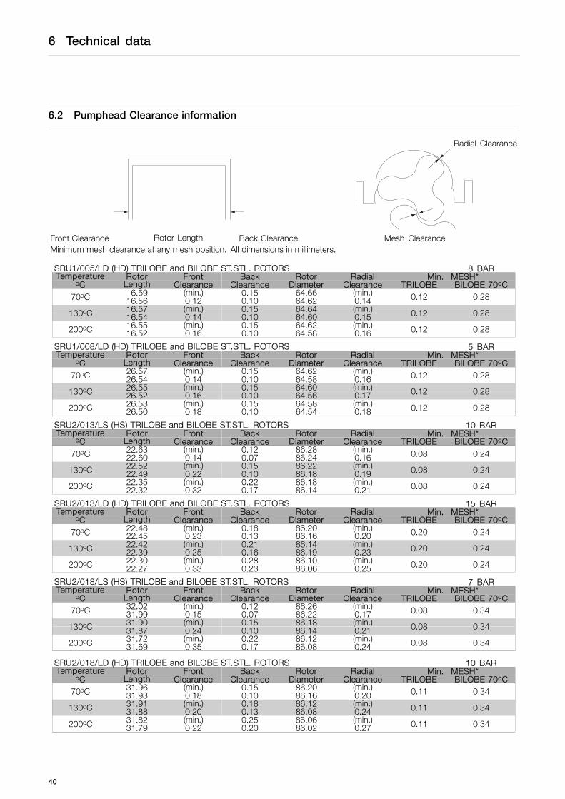
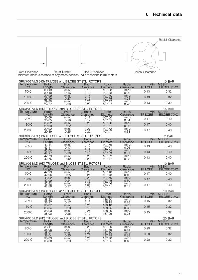
6.2 Pumphead Clearance information
Radial Clearance
Front Clearance Rotor Length Back Clearance Mesh ClearanceMinimum mesh clearance at any mesh position. All dimensions in millimeters.
SRU1/005/LD (HD) TRILOBE and BILOBE ST.STL. ROTORS 8 BARTemperature Rotor Front Back Rotor Radial Min. MESH*
oC Length Clearance Clearance Diameter Clearance TRILOBE BILOBE 70oC16.59 (min.) 0.15 64.66 (min.)70oC 16.56 0.12 0.10 64.62 0.14 0.12 0.2816.57 (min.) 0.15 64.64 (min.)130oC 16.54 0.14 0.10 64.60 0.15 0.12 0.2816.55 (min.) 0.15 64.62 (min.)200oC 16.52 0.16 0.10 64.58 0.16 0.12 0.28
SRU1/008/LD (HD) TRILOBE and BILOBE ST.STL. ROTORS 5 BARTemperature Rotor Front Back Rotor Radial Min. MESH*
oC Length Clearance Clearance Diameter Clearance TRILOBE BILOBE 70oC26.57 (min.) 0.15 64.62 (min.)70oC 26.54 0.14 0.10 64.58 0.16 0.12 0.2826.55 (min.) 0.15 64.60 (min.)130oC 26.52 0.16 0.10 64.56 0.17 0.12 0.2826.53 (min.) 0.15 64.58 (min.)200oC 26.50 0.18 0.10 64.54 0.18 0.12 0.28
SRU2/013/LS (HS) TRILOBE and BILOBE ST.STL. ROTORS 10 BARTemperature Rotor Front Back Rotor Radial Min. MESH*
oC Length Clearance Clearance Diameter Clearance TRILOBE BILOBE 70oC22.63 (min.) 0.12 86.28 (min.)70oC 22.60 0.14 0.07 86.24 0.16 0.08 0.2422.52 (min.) 0.15 86.22 (min.)130oC 22.49 0.22 0.10 86.18 0.19 0.08 0.2422.35 (min.) 0.22 86.18 (min.)200oC 22.32 0.32 0.17 86.14 0.21 0.08 0.24
SRU2/013/LD (HD) TRILOBE and BILOBE ST.STL. ROTORS 15 BARTemperature Rotor Front Back Rotor Radial Min. MESH*
oC Length Clearance Clearance Diameter Clearance TRILOBE BILOBE 70oC22.48 (min.) 0.18 86.20 (min.)70oC 22.45 0.23 0.13 86.16 0.20 0.20 0.2422.42 (min.) 0.21 86.14 (min.)130oC 22.39 0.25 0.16 86.19 0.23 0.20 0.2422.30 (min.) 0.28 86.10 (min.)200oC 22.27 0.33 0.23 86.06 0.25 0.20 0.24
SRU2/018/LS (HS) TRILOBE and BILOBE ST.STL. ROTORS 7 BARTemperature Rotor Front Back Rotor Radial Min. MESH*
oC Length Clearance Clearance Diameter Clearance TRILOBE BILOBE 70oC32.02 (min.) 0.12 86.26 (min.)70oC 31.99 0.15 0.07 86.22 0.17 0.08 0.3431.90 (min.) 0.15 86.18 (min.)130oC 31.87 0.24 0.10 86.14 0.21 0.08 0.3431.72 (min.) 0.22 86.12 (min.)200oC 31.69 0.35 0.17 86.08 0.24 0.08 0.34
SRU2/018/LD (HD) TRILOBE and BILOBE ST.STL. ROTORS 10 BARTemperature Rotor Front Back Rotor Radial Min. MESH*
oC Length Clearance Clearance Diameter Clearance TRILOBE BILOBE 70oC31.96 (min.) 0.15 86.20 (min.)70oC 31.93 0.18 0.10 86.16 0.20 0.11 0.3431.91 (min.) 0.18 86.12 (min.)130oC 31.88 0.20 0.13 86.08 0.24 0.11 0.3431.82 (min.) 0.25 86.06 (min.)200oC 31.79 0.22 0.20 86.02 0.27 0.11 0.34
40
6 Technical data
Radial Clearance
Front Clearance Rotor Length Back Clearance Mesh ClearanceMinimum mesh clearance at any mesh position. All dimensions in millimeters
SRU3/027/LS (HS) TRILOBE and BILOBE ST.STL. ROTORS 10 BARTemperature Rotor Front Back Rotor Radial Min. MESH*
oC Length Clearance Clearance Diameter Clearance TRILOBE BILOBE 70oC30.13 (min.) 0.15 107.88 (min.)70oC 30.10 0.16 0.10 107.83 0.20 0.13 0.3229.99 (min.) 0.18 107.80 (min.)130oC 29.96 0.27 0.13 107.75 0.24 0.13 0.3229.80 (min.) 0.25 107.72 (min.)200oC 29.77 0.39 0.20 107.67 0.28 0.13 0.32
SRU3/027/LD (HD) TRILOBE and BILOBE ST.STL. ROTORS 15 BARTemperature Rotor Front Back Rotor Radial Min. MESH*
oC Length Clearance Clearance Diameter Clearance TRILOBE BILOBE 70oC30.08 (min.) 0.17 107.60 (min.)70oC 30.05 0.19 0.12 107.55 0.34 0.17 0.4030.02 (min.) 0.20 107.56 (min.)130oC 29.99 0.22 0.15 107.51 0.36 0.17 0.4029.92 (min.) 0.27 107.52 (min.)200oC 29.89 0.25 0.22 107.47 0.38 0.17 0.40
SRU3/038/LS (HS) TRILOBE and BILOBE ST.STL. ROTORS 7 BARTemperature Rotor Front Back Rotor Radial Min. MESH*
oC Length Clearance Clearance Diameter Clearance TRILOBE BILOBE 70oC43.14 (min.) 0.15 107.76 (min.)70oC 43.11 0.17 0.10 107.71 0.26 0.13 0.4043.00 (min.) 0.18 107.64 (min.)130oC 42.97 0.28 0.13 107.59 0.32 0.13 0.4042.79 (min.) 0.25 107.52 (min.)200oC 42.76 0.42 0.20 107.47 0.38 0.13 0.40
SRU3/038/LD (HD) TRILOBE and BILOBE ST.STL. ROTORS 10 BARTemperature Rotor Front Back Rotor Radial Min. MESH*
oC Length Clearance Clearance Diameter Clearance TRILOBE BILOBE 70oC42.99 (min.) 0.26 107.48 (min.)70oC 42.96 0.25 0.21 107.43 0.40 0.17 0.4043.02 (min.) 0.20 107.50 (min.)130oC 42.99 0.24 0.15 107.45 0.39 0.17 0.4042.92 (min.) 0.27 107.46 (min.)200oC 42.89 0.27 0.22 107.41 0.41 0.17 0.40
SRU4/055/LS (HS) TRILOBE and BILOBE ST.STL. ROTORS 10 BARTemperature Rotor Front Back Rotor Radial Min. MESH*
oC Length Clearance Clearance Diameter Clearance TRILOBE BILOBE 70oC38.20 (min.) 0.15 138.20 (min.)70oC 38.17 0.17 0.10 138.15 0.18 0.15 0.3238.07 (min.) 0.20 138.10 (min.)130oC 38.04 0.20 0.15 138.05 0.23 0.15 0.3238.03 (min.) 0.24 138.00 (min.)200oC 38.00 0.25 0.19 137.95 0.28 0.15 0.32
SRU4/055/LD (HD) TRILOBE and BILOBE ST.STL. ROTORS 20 BARTemperature Rotor Front Back Rotor Radial Min. MESH*
oC Length Clearance Clearance Diameter Clearance TRILOBE BILOBE 70oC38.11 (min.) 0.20 137.90 (min.)70oC 38.08 0.21 0.15 137.85 0.33 0.20 0.3238.07 (min.) 0.20 137.80 (min.)130oC 38.04 0.25 0.15 137.75 0.38 0.20 0.3238.03 (min.) 0.20 137.70 (min.)200oC 38.00 0.29 0.15 137.65 0.43 0.20 0.32
41

6 Technical data
Radial Clearance
Front Clearance Rotor Length Back Clearance Mesh ClearanceMinimum mesh clearance at any mesh position. All dimensions in millimeters
SRU4/079/LS (HS) TRILOBE and BILOBE ST.STL. ROTORS 7 BARTemperature Rotor Front Back Rotor Radial Min. MESH*
oC Length Clearance Clearance Diameter Clearance TRILOBE BILOBE 70oC54.99 (min.) 0.17 137.96 (min.)70oC 54.96 0.20 0.12 137.91 0.30 0.15 0.3254.88 (min.) 0.22 137.82 (min.)130oC 54.85 0.25 0.17 137.77 0.37 0.15 0.3254.75 (min.) 0.27 137.66 (min.)200oC 54.72 0.30 0.22 137.61 0.45 0.15 0.32
SRU4/079/LD (HD) TRILOBE and BILOBE ST.STL. ROTORS 15 BARTemperature Rotor Front Back Rotor Radial Min. MESH*
oC Length Clearance Clearance Diameter Clearance TRILOBE BILOBE 70oC54.81 (min.) 0.23 137.64 (min.)70oC 54.78 0.32 0.18 137.59 0.46 0.20 0.3254.77 (min.) 0.23 137.50 (min.)130oC 54.74 0.36 0.18 137.45 0.53 0.20 0.32
54.73 (min.) 0.23 137.34 (min.)200oC54.70 0.40 0.18 137.29 0.61
0.20 0.32
SRU5/116/LS (HS) TRILOBE and BILOBE ST.STL. ROTORS 10 BARTemperature Rotor Front Back Rotor Radial Min. MESH*
oC Length Clearance Clearance Diameter Clearance TRILOBE BILOBE 70oC51.07 (min.) 0.18 172.58 (min.)70oC 51.04 0.25 0.13 172.53 0.28 0.20 0.3150.99 (min.) 0.18 172.46 (min.)130oC 50.96 0.33 0.13 172.41 0.34 0.20 0.3150.94 (min.) 0.18 172.32 (min.)200oC 50.91 0.38 0.13 172.27 0.41 0.20 0.31
SRU5/116/LD (HD) TRILOBE and BILOBE ST.STL. ROTORS 20 BARTemperature Rotor Front Back Rotor Radial Min. MESH*
oC Length Clearance Clearance Diameter Clearance TRILOBE BILOBE 70oC50.98 (min.) 0.20 172.22 (min.) 0.20 0.3170oC 51.04 0.29 0.15 172.17 0.4650.93 (min.) 0.20 172.10 (min.) 0.20 0.31130oC 50.90 0.37 0.15 172.05 0.5250.79 (min.) 0.20 171.96 (min.) 0.20 0.31200oC 50.76 0.51 0.15 171.91 0.59
SRU5/168/LS (HS) TRILOBE and BILOBE ST.STL. ROTORS 7 BARTemperature Rotor Front Back Rotor Radial Min. MESH*
oC Length Clearance Clearance Diameter Clearance TRILOBE BILOBE 70oC74.06 (min.) 0.20 172.27 (min.) 0.20 0.3170oC 74.03 0.30 0.15 172.22 0.4473.93 (min.) 0.20 172.09 (min.) 0.20 0.31130oC 73.90 0.43 0.15 172.04 0.5373.79 (min.) 0.20 171.89 (min.) 0.20 0.31200oC 73.76 0.57 0.15 171.84 0.63
SRU5/168/LD (HD) TRILOBE and BILOBE ST.STL. ROTORS 20 BARTemperature Rotor Front Back Rotor Radial Min. MESH*
oC Length Clearance Clearance Diameter Clearance TRILOBE BILOBE 70oC73.91 (min.) 0.27 171.97 (min.)70oC 73.88 0.38 0.22 171.92 0.59 0.20 0.7173.87 (min.) 0.27 171.79 (min.)130oC 73.84 0.42 0.22 171.74 0.68 0.20 0.7173.82 (min.) 0.27 171.59 (min.)200oC 73.79 0.47 0.22 171.54 0.78 0.20 0.71
42
6 Technical data
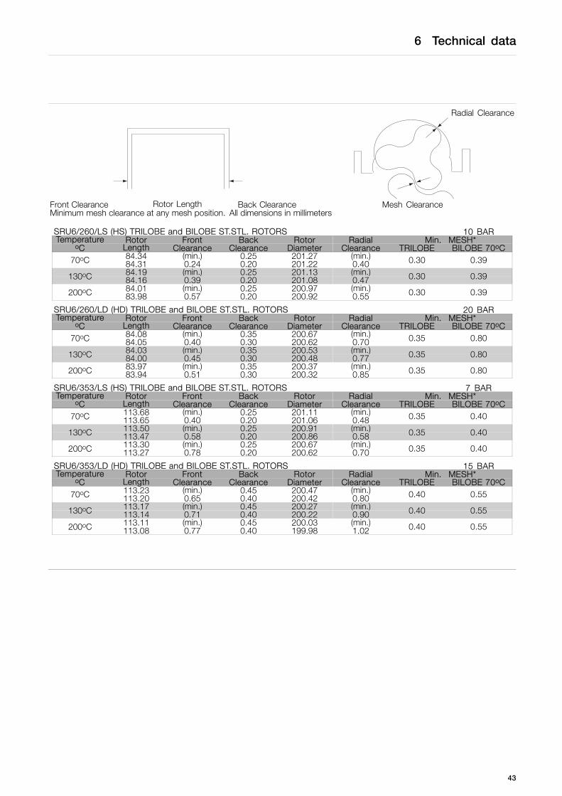
Radial Clearance
Front Clearance Rotor Length Back Clearance Mesh ClearanceMinimum mesh clearance at any mesh position. All dimensions in millimeters
SRU6/260/LS (HS) TRILOBE and BILOBE ST.STL. ROTORS 10 BARTemperature Rotor Front Back Rotor Radial Min. MESH*
oC Length Clearance Clearance Diameter Clearance TRILOBE BILOBE 70oC84.34 (min.) 0.25 201.27 (min.)70oC 84.31 0.24 0.20 201.22 0.40 0.30 0.3984.19 (min.) 0.25 201.13 (min.)130oC 84.16 0.39 0.20 201.08 0.47 0.30 0.3984.01 (min.) 0.25 200.97 (min.)200oC 83.98 0.57 0.20 200.92 0.55 0.30 0.39
SRU6/260/LD (HD) TRILOBE and BILOBE ST.STL. ROTORS 20 BARTemperature Rotor Front Back Rotor Radial Min. MESH*
oC Length Clearance Clearance Diameter Clearance TRILOBE BILOBE 70oC84.08 (min.) 0.35 200.67 (min.)70oC 84.05 0.40 0.30 200.62 0.70 0.35 0.8084.03 (min.) 0.35 200.53 (min.)130oC 84.00 0.45 0.30 200.48 0.77 0.35 0.8083.97 (min.) 0.35 200.37 (min.)200oC 83.94 0.51 0.30 200.32 0.85 0.35 0.80
SRU6/353/LS (HS) TRILOBE and BILOBE ST.STL. ROTORS 7 BARTemperature Rotor Front Back Rotor Radial Min. MESH*
oC Length Clearance Clearance Diameter Clearance TRILOBE BILOBE 70oC113.68 (min.) 0.25 201.11 (min.)70oC 113.65 0.40 0.20 201.06 0.48 0.35 0.40113.50 (min.) 0.25 200.91 (min.)130oC 113.47 0.58 0.20 200.86 0.58 0.35 0.40113.30 (min.) 0.25 200.67 (min.)200oC 113.27 0.78 0.20 200.62 0.70 0.35 0.40
SRU6/353/LD (HD) TRILOBE and BILOBE ST.STL. ROTORS 15 BARTemperature Rotor Front Back Rotor Radial Min. MESH*
oC Length Clearance Clearance Diameter Clearance TRILOBE BILOBE 70oC113.23 (min.) 0.45 200.47 (min.)70oC 113.20 0.65 0.40 200.42 0.80 0.40 0.55113.17 (min.) 0.45 200.27 (min.)130oC 113.14 0.71 0.40 200.22 0.90 0.40 0.55113.11 (min.) 0.45 200.03 (min.)200oC 113.08 0.77 0.40 199.98 1.02 0.40 0.55
43

7 Parts list
7.1 SRU1 Pump Range
76545
4749
5350
5251
5458
88A 3
8B
1312
1110
9
15 14 16
2 14A
4
48
46
58
56
3638
3940
26
2730
2331
32
18
25
24
2220
17
TD 243-052
44

7 Parts list
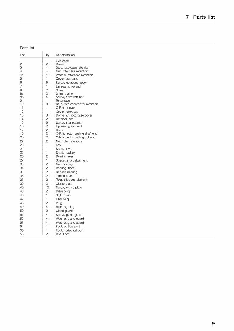
Parts list
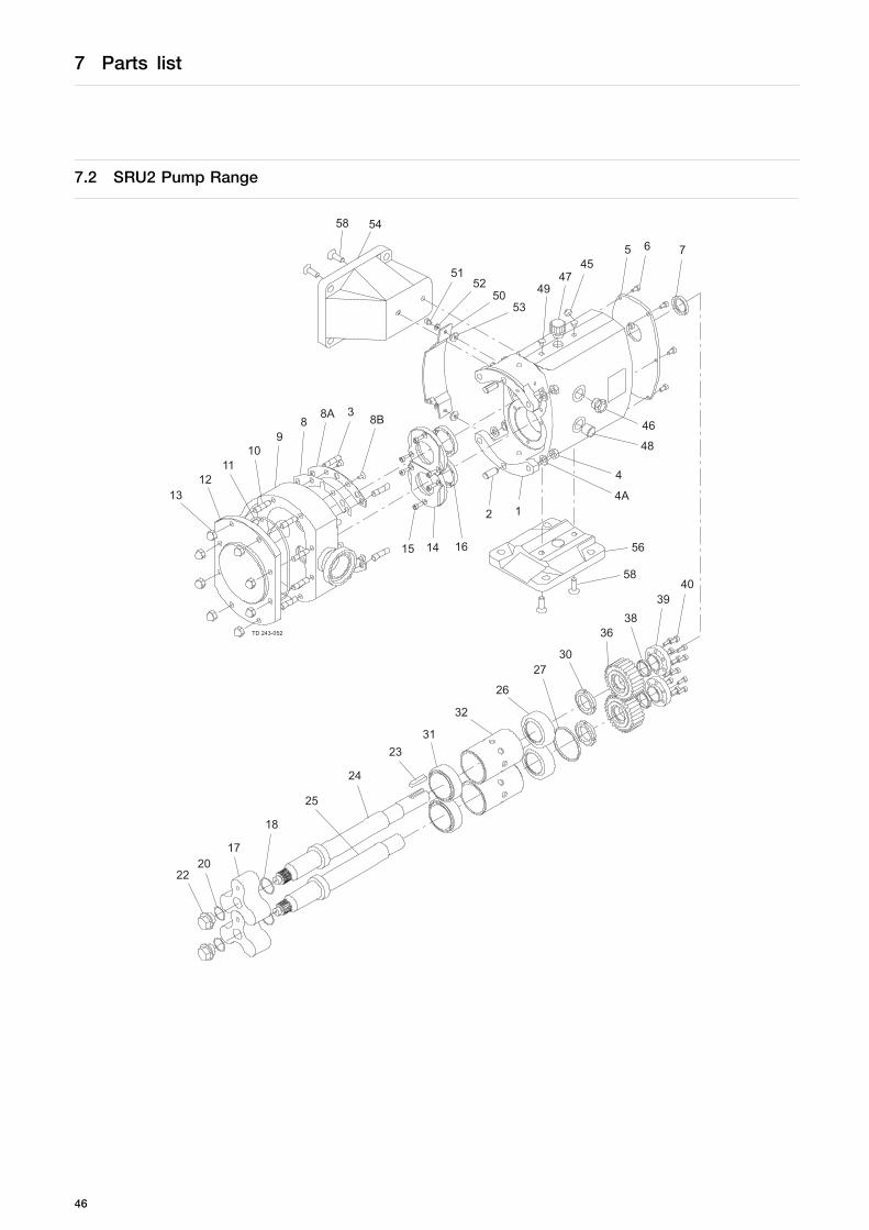
Pos. Qty Denomination
1 1 Gearcase2 2 Dowel3 4 Stud, rotorcase retention4 4 Nut, rotorcase retention4a 4 Washer, rotorcase retention5 1 Cover, gearcase6 6 Screw, gearcase cover7 1 Lip seal, drive end8 2 Shim8a 2 Shim retainer8b 4 Screw, shim retainer9 1 Rotorcase10 4 Stud, rotorcase/cover retention11 1 O-Ring, cover - plain12 1 Cover, rotorcase13 4 Dome nut, rotorcase cover14 2 Retainer, seal15 6 Screw, seal retainer16 2 Lip seal, gland end17 2 Rotor18 2 O-Ring, rotor sealing shaft end20 2 O-Ring, rotor sealing nut end22 2 Nut, rotor retention23 1 Key24 1 Shaft, drive25 1 Shaft, auxiliary26 2 Bearing, rear27 1 Spacer, shaft abutment30 2 Nut, bearing31 2 Bearing, front32 2 Spacer, bearing36 2 Timing gear38 2 Torque locking element39 2 Clamp plate40 12 Screw, clamp plate45 2 Drain plug46 1 Sight glass47 1 Filler plug48 2 Plug49 4 Blanking plug50 2 Gland guard51 4 Screw, gland guard52 4 Washer, gland guard screw53 4 Washer, gland guard54 1 Foot, vertical port56 1 Foot, horizontal port58 2 Bolt, Foot
45
7 Parts list
7.2 SRU2 Pump Range
76545
4749
5350
5251
5458
88A 3
8B
1312
1110
9
15 14 16
2 14A
4
48
46
58
56
3638
3940
26
2730
2331
32
18
25
24
2220
17
TD 243-052
46

7 Parts list
Parts list
Pos. Qty Denomination
1 1 Gearcase2 2 Dowel3 4 Stud, rotorcase retention4 4 Nut, rotorcase retention4a 4 Washer, rotorcase retention5 1 Cover, gearcase6 6 Screw, gearcase cover7 1 Lip seal, drive end8 2 Shim8a 2 Shim retainer8b 4 Screw, shim retainer9 1 Rotorcase10 4 Stud, rotorcase/cover retention11 1 O-Ring, cover12 1 Cover, rotorcase13 4 Dome nut, rotorcase cover14 2 Retainer, seal15 6 Screw, seal retainer16 2 Lip seal, gland end17 2 Rotor18 2 O-Ring, rotor sealing shaft end20 2 O-Ring, rotor sealing nut end22 2 Nut, rotor retention23 1 Key24 1 Shaft, drive25 1 Shaft, auxiliary26 2 Bearing, rear27 1 Spacer, shaft abutment30 2 Nut, bearing31 2 Bearing, front32 2 Spacer, bearing36 2 Timing gear38 2 Torque locking element39 2 Clamp plate40 12 Screw, clamp plate45 2 Drain plug46 1 Sight glass47 1 Filler plug48 2 Plug49 4 Blanking plug50 2 Gland guard51 4 Screw, gland guard52 4 Washer, gland guard screw53 4 Washer, gland guard54 1 Foot, vertical port56 1 Foot, horizontal port58 2 Bolt, Foot
47

7 Parts list
7.3 SRU3 Pump Range
76545
4749
5350
5251
5458
88A 3
8B
1312
1110
9
15 14 16
2 14A
4
48
46
58
56
3638
3940
26
2730
2331
32
18
25
24
2220
17
TD 243-052
48
7 Parts list
Parts list
Pos. Qty Denomination
1 1 Gearcase2 2 Dowel3 4 Stud, rotorcase retention4 4 Nut, rotorcase retention4a 4 Washer, rotorcase retention5 1 Cover, gearcase6 6 Screw, gearcase cover7 1 Lip seal, drive end8 2 Shim8a 2 Shim retainer8b 4 Screw, shim retainer9 1 Rotorcase10 8 Stud, rotorcase/cover retention11 1 O-Ring, cover12 1 Cover, rotorcase13 8 Dome nut, rotorcase cover14 2 Retainer, seal15 6 Screw, seal retainer16 2 Lip seal, gland end17 2 Rotor18 2 O-Ring, rotor sealing shaft end20 2 O-Ring, rotor sealing nut end22 2 Nut, rotor retention23 1 Key24 1 Shaft, drive25 1 Shaft, auxiliary26 2 Bearing, rear27 1 Spacer, shaft abutment30 2 Nut, bearing31 2 Bearing, front32 2 Spacer, bearing36 2 Timing gear38 2 Torque locking element39 2 Clamp plate40 12 Screw, clamp plate45 2 Drain plug46 1 Sight glass47 1 Filler plug48 2 Plug49 4 Blanking plug50 2 Gland guard51 4 Screw, gland guard52 4 Washer, gland guard53 4 Washer, gland guard54 1 Foot, vertical port56 1 Foot, horizontal port58 2 Bolt, Foot
49

7 Parts list
7.4 SRU4 Pump Range
76 54547
4953
5052
51
5458
8 8a 3 8b
1312
1110
9
1514
16 21 4a
4
48
46
58
56
3637
3026
2726
28
23
3134
18
25
24
2220
17
TD 243-053
3129
50
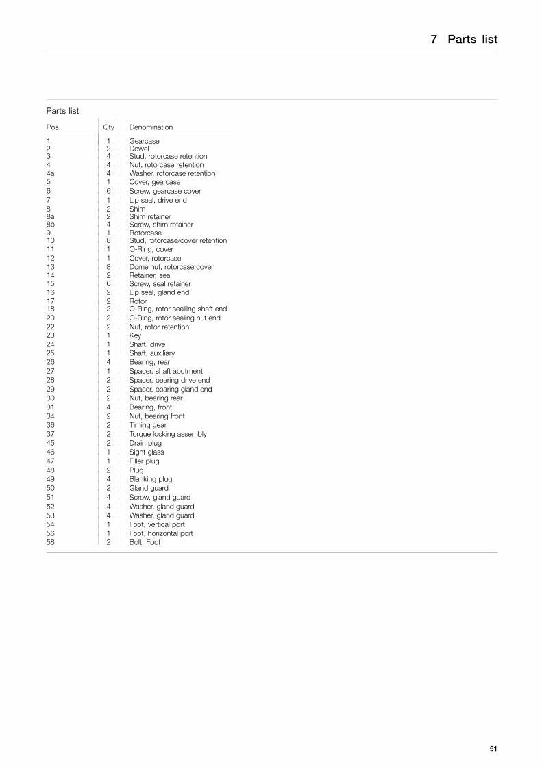
7 Parts list
Parts list
Pos. Qty Denomination
1 1 Gearcase2 2 Dowel3 4 Stud, rotorcase retention4 4 Nut, rotorcase retention4a 4 Washer, rotorcase retention5 1 Cover, gearcase6 6 Screw, gearcase cover7 1 Lip seal, drive end8 2 Shim8a 2 Shim retainer8b 4 Screw, shim retainer9 1 Rotorcase10 8 Stud, rotorcase/cover retention11 1 O-Ring, cover12 1 Cover, rotorcase13 8 Dome nut, rotorcase cover14 2 Retainer, seal15 6 Screw, seal retainer16 2 Lip seal, gland end17 2 Rotor18 2 O-Ring, rotor sealilng shaft end20 2 O-Ring, rotor sealing nut end22 2 Nut, rotor retention23 1 Key24 1 Shaft, drive25 1 Shaft, auxiliary26 4 Bearing, rear27 1 Spacer, shaft abutment28 2 Spacer, bearing drive end29 2 Spacer, bearing gland end30 2 Nut, bearing rear31 4 Bearing, front34 2 Nut, bearing front36 2 Timing gear37 2 Torque locking assembly45 2 Drain plug46 1 Sight glass47 1 Filler plug48 2 Plug49 4 Blanking plug50 2 Gland guard51 4 Screw, gland guard52 4 Washer, gland guard53 4 Washer, gland guard54 1 Foot, vertical port56 1 Foot, horizontal port58 2 Bolt, Foot
51
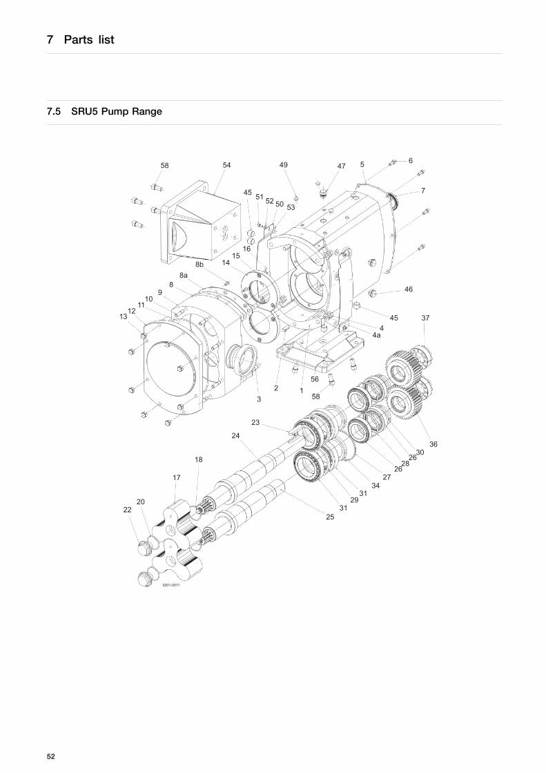
7 Parts list
7.5 SRU5 Pump Range
58 54
50525145
53
49 5
7
647
16
1312
1110
88a
8b 1415
23
24
18
17
123
46
4a4
45
56
37
58
2220
36
2531
2931
3427
2628
2630
3201-0011
9
52

7 Parts list
Parts list
Pos. Qty Denomination
1 1 Gearcase2 2 Dowel3 4 Stud, rotorcase retention4 4 Nut, rotorcase retention4a 4 Washer, rotorcase retention5 1 Cover, gearcase6 6 Screw, gearcase cover7 1 Lip seal, drive end8 2 Shim8a 2 Shim retainer8b 4 Screw, shim retainer9 1 Rotorcase10 8 Stud, rotorcase/cover retention11 1 O-Ring, cover12 1 Cover, rotorcase13 8 Dome nut, rotorcase cover14 2 Retainer, seal15 6 Screw, seal retainer16 2 Lip seal, gland end17 2 Rotor18 2 O-Ring, rotor sealing shaft end20 2 O-Ring, rotor sealing nut end22 2 Nut, rotor retention23 1 Key24 1 Shaft, drive25 1 Shaft, auxiliary26 4 Bearing, rear27 1 Spacer, shaft abutment28 2 Spacer, bearing drive end29 2 Spacer, bearing gland end30 2 Nut, bearing rear31 4 Bearing, front34 2 Nut, bearing front36 2 Timing gear37 2 Torque locking assembly45 7 Drain plug46 1 Sight glass47 1 Filler plug50 2 Gland guard51 4 Screw, gland guard52 4 Washer, gland guard53 4 Washer, gland guard54 1 Foot, vertical port56 1 Foot, horizontal port58 4 Bolt, foot
53

7 Parts list
7.6 SRU6 Pump Range
58 54
50525145
53
49 5
7
647
16
1312
1110
88a
8b 1415
23
24
18
17
123
46
4a4
45
56
37
58
2220
36
2531
2931
3427
2628
2630
3201-0012
9
19
54

7 Parts list
Parts list
Pos. Qty Denomination
1 1 Gearcase2 2 Dowel3 4 Stud, rotorcase retention4 4 Nut, rotorcase retention4a 4 Washer, rotorcase retention5 1 Cover, gearcase6 6 Screw, gearcase cover7 1 Lip seal, drive end8 2 Shim8a 2 Shim retainer8b 4 Screw, shim retainer9 1 Rotorcase10 8 Stud, rotorcase/cover retention11 1 O-Ring, cover12 1 Cover, rotorcase13 8 Dome nut, rotorcase cover14 2 Retainer, seal15 6 Screw, seal retainer16 2 Lip seal, gland end17 2 Rotor18 2 O-Ring, rotor sealing shaft end19 2 Torque locking assembly20 2 O-Ring, rotor sealing nut end22 2 Nut, rotor retention23 1 Key24 1 Shaft, drive25 1 Shaft, auxiliary26 4 Bearing, rear27 1 Spacer, shaft abutment28 2 Spacer, bearing drive end29 2 Spacer, bearing gland end30 2 Nut, bearing rear31 4 Bearing, front34 2 Nut, bearing front36 2 Timing gear37 2 Torque locking assembly45 7 Drain plug46 1 Sight glass47 1 Filler plug50 2 Gland guard51 4 Screw, gland guard52 4 Washer, gland guard53 4 Washer, gland guard54 1 Foot, vertical port56 1 Foot, horizontal port58 4 Bolt, foot
55

How to contact Alfa LavalContact details for all countries arecontinually updated on our website.Please visit www.alfalaval.com to access the information directly.
© Alfa Laval Corporate ABThis document and its contents is owned by Alfa Laval Corporate AB and protected by laws governing intellectual property and thereto related rights. It is the responsibility of the user of thisdocument to comply with all applicable intellectual property laws. Without limiting any rights related to this document, no part of this document may be copied, reproduced or transmitted in anyform or by any means (electronic, mechanical, photocopying, recording, or otherwise), or for any purpose, without the expressed permission of Alfa Laval Corporate AB. Alfa Laval Corporate ABwill enforce its rights related to this document to the fullest extent of the law, including the seeking of criminal prosecution.