Embed Size (px)
Citation preview

Cast IronOil LubeStationary Air Compressor
Instructionmanual
IMPORTANTPlease make certain that the person who isto use this equipment carefully reads andunderstands these instructions beforestarting operations.
Part No. D28176-049-1
ESPAÑOL: PÁGINA 29FRANÇAIS: PAGE 57
To learn more about Porter-Cable visit our website at:
http://www.porter-cable.com
ModelC7510
Copyright © 2003 Porter-Cable Corporation
The Model and Serial No. plate is located on the frame.Record these numbers in the spaces below and retain forfuture reference.
Model No.
Type
Serial No.

2- ENGD28176
SAFETY GUIDELINES - DEFINITIONS
Indicates an imminentlyhazardous situation
which, if not avoided, will result in deathor serious injury.
Indicates a potentiallyhazardous situation
which, if not avoided, could result indeath or serious injury.
Indicates a potentiallyhazardous situation
which, if not avoided, may result inminor or moderate injury.
Used without the safetyalert symbol indicates a
potentially hazardous situation which, ifnot avoided, may result in propertydamage.
This manual contains information that is important for you to know andunderstand. This information relates to protecting YOUR SAFETY andPREVENTING EQUIPMENT PROBLEMS. To help you recognize thisinformation, we use the symbols below. Please read the manual and payattention to these symbols.
IMPORTANT SAFETY INSTRUCTIONSSome dust created by power sanding, sawing, grinding,drilling, and other construction activities contains chemicals
known (to the State of California) to cause cancer, birth defects or otherreproductive harm. Some example of these chemicals are:● lead from lead-based paints● crystalline silica from bricks and cement and other masonry products● arsenic and chromium from chemically-treated lumberYour risk from these exposures varies, depending on how often you do thistype of work. To reduce your exposure to these chemicals: work in a wellventilated area, and work with approved safety equipment, always wearMSHA/NIOSH approved, properly fitting face mask or respirator when usingsuch tools.When using air tools, basic safety precautions should always be followed toreduce the risk of of personal injury.

3- ENG D28176
IMPORTANT SAFETY INSTRUCTIONS
Save these instructions
Improper operation or maintenance of this product could result in serious injury andproperty damage. Read and understand all warnings and operation instructions beforeusing this equipment.
HAZARD
WARNING: Risk of explosion or fire
How To Prevent ItWhat Could Happen
It is normal for electrical contactswithin the motor and pressure switch tospark.
If electrical sparks from compressorcome into contact with flammablevapors, they may ignite, causing fire orexplosion.
Restricting any of the compressorventilation openings will cause seriousoverheating and could cause fire.
Unattended operation of this productcould result in personal injury orproperty damage. To reduce the risk offire, do not allow the compressor tooperate unattended.
Always operate the compressor in a wellventilated area free of combustiblematerials, gasoline, or solvent vapors.
If spraying flammable materials, locatecompressor at least 20 feet away fromspray area. An additional length of hosemay be required.Store flammable materials in a securelocation away from compressor.
Never place objects against or on topof compressor. Operate compressor inan open area at least 12 inches awayfrom any wall or obstruction that wouldrestrict the flow of fresh air to theventilation openings.Operate compressor in a clean, dry wellventilated area. Do not operate unitindoors or in any confined area.
Always remain in attendance with theproduct when it is operating.Always disconnect electrical power bymoving pressure switch lever to the offposition and drain tank daily or aftereach use.

4- ENGD28176
WARNING: Risk of Bursting
Air Tank: The following conditions could lead to a weakening of the tank, and resultin a violent tank explosion and could cause property damage or serious injury.
How To Prevent ItWhat Could Happen
WARNING: Risk from Flying Objects
The compressed air stream can causesoft tissue damage to exposed skinand can propel dirt, chips, looseparticles, and small objects at highspeed, resulting in property damage orpersonal injury.
Always wear ANSI Z87.1 approved safetyglasses with side shields when using thecompressor.
Never point any nozzle or sprayertoward any part of the body or at otherpeople or animals.
Always turn the compressor off andbleed pressure from the air hose and tankbefore attempting maintenance, attachingtools or accessories.
HAZARD
HAZARD
Drain tank daily or after each use. Iftank develops a leak, replace itimmediately with a new tank or replacethe entire compressor.
Failure to properly drain condensedwater from tank, causing rust andthinning of the steel tank.
Modifications or attempted repairs to the tank.
Unauthorized modifications to the unloader valve, safety valve, or any other components which control tank pressure.
Never drill into, weld, or make anymodifications to the tank or itsattachments.
Excessive vibration can weaken the air tank and cause rupture or explosion
The tank is designed to withstand specificoperating pressures. Never makeadjustments or parts substitutions toalter the factory set operatingpressures.
For essential control of air pressure, youmust install a pressure regulator andpressure gauge to the air outlet (if notequipped) of your compressor. Follow theequipment manufacturersrecommendation and never exceed themaximum allowable pressure rating ofattachments. Never use compressor toinflate small low pressure objects suchas children’s toys, footballs,basketballs, etc.
ATTACHMENTS & ACCESSORIES:Exceeding the pressure rating of airtools, spray guns, air operatedaccessories, tires, and other inflatablescan cause them to explode or fly apart,and could result in serious injury.
How To Prevent ItWhat Could Happen

5- ENG D28176
WARNING: Risk to Breathing
WARNING: Risk of Electrical Shock
HAZARD
HAZARD
Your air compressor is powered byelectricity. Like any other electricallypowered device, If it is not usedproperly it may cause electric shock.
Repairs attempted by unqualifiedpersonnel can result in serious injuryor death by electrocution.
Electrical Grounding: Failure to provideadequate grounding to this productcould result in serious injury or deathfrom electrocution. See grounding instructions.
Never operate the compressor outdoorswhen it is raining or in wet conditions.Never operate compressor withprotective covers removed or damaged.
Any electrical wiring or repairs requiredon this product should be performed byauthorized service center personnel inaccordance with national and localelectrical codes.
Make certain that the electrical circuit towhich the compressor is connectedprovides proper electrical grounding,correct voltage and adequate fuseprotection.
The compressed air directly from yourcompressor is not safe for breathing.The air stream may contain carbonmonoxide, toxic vapors, or solidparticles from the tank. Breathing thesecontaminants can cause serious injuryor death.
Sprayed materials such as paint, paintsolvents, paint remover, insecticides,weed killers, may contain harmfulvapors and poisons.
Air obtained directly from the compressorshould never be used to supply air forhuman consumption. In order to use airproduced by this compressor forbreathing, suitable filters and in-linesafety equipment must be properlyinstalled. In-line filters and safetyequipment used in conjunction with thecompressor must be capable of treatingair to all applicable local and federalcodes prior to human consumption.
Work in an area with good crossventilation. Read and follow the safetyinstructions provided on the label orsafety data sheets for the materials youare spraying. Use a NIOSH/ MSHAapproved respirator designed for use withyour specific application.
How To Prevent ItWhat Could Happen
How To Prevent ItWhat Could Happen
6- ENGD28176
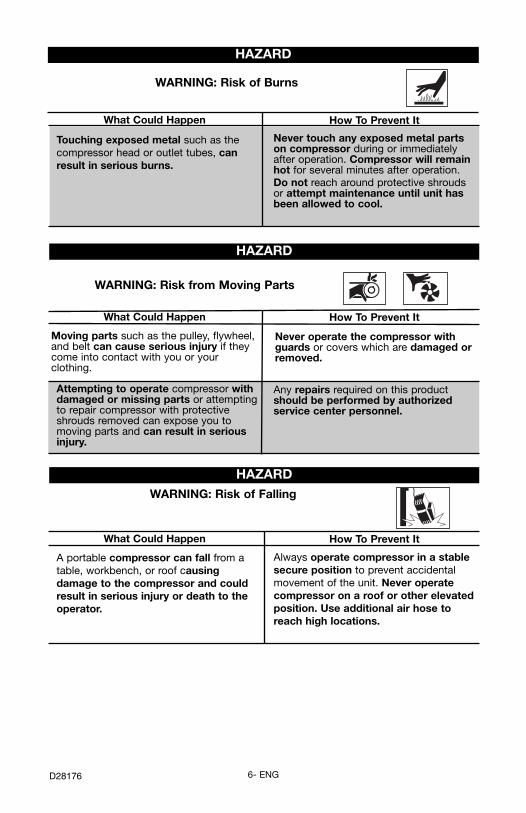
WARNING: Risk of Burns
Touching exposed metal such as thecompressor head or outlet tubes, canresult in serious burns.
Never touch any exposed metal partson compressor during or immediatelyafter operation. Compressor will remainhot for several minutes after operation.Do not reach around protective shroudsor attempt maintenance until unit hasbeen allowed to cool.
WARNING: Risk from Moving Parts
Never operate the compressor withguards or covers which are damaged orremoved.
Moving parts such as the pulley, flywheel,and belt can cause serious injury if theycome into contact with you or yourclothing.
WARNING: Risk of Falling
A portable compressor can fall from atable, workbench, or roof causingdamage to the compressor and couldresult in serious injury or death to theoperator.
Always operate compressor in a stablesecure position to prevent accidentalmovement of the unit. Never operatecompressor on a roof or other elevatedposition. Use additional air hose toreach high locations.
HAZARD
HAZARD
HAZARD
Any repairs required on this productshould be performed by authorizedservice center personnel.
Attempting to operate compressor withdamaged or missing parts or attemptingto repair compressor with protectiveshrouds removed can expose you tomoving parts and can result in seriousinjury.
How To Prevent ItWhat Could Happen
How To Prevent ItWhat Could Happen
How To Prevent ItWhat Could Happen

7- ENG D28176
Review and understand all instructionsand warnings in this manual.Become familiar with the operation andcontrols of the air compressor.Keep operating area clear of all persons,pets, and obstacles.Keep children away from the aircompressor at all times.Do not operate the product whenfatigued or under the influence ofalcohol or drugs. Stay alert at all times.Never defeat the safety features of thisproduct.Equip area of operation with a fireextinguisher.Do not operate machine with missing,broken, or unauthorized parts.
WARNING: Risk of Unsafe Operation
Unsafe operation of your air compressorcould lead to serious injury or death toyou or others.
HAZARD
WARNING: Risk of Serious Injury or Property Damage WhenTransporting Compressor
Oil can leak or spill and could result infire or breathing hazard; serious injury ordeath can result. Oil leaks will damagecarpet, paint or other surfaces invehicles or trailers.
Always place COMPRESSOR on aprotective mat when transporting toprotect against damage to vehicle fromleaks. Remove COMPRESSOR fromvehicle immediately upon arrival at yourdestination.
(Fire, Inhalation, Damage to Vehicle Surfaces)
HAZARD
SAVE THESE INSTRUCTIONS
How To Prevent ItWhat Could Happen
How To Prevent ItWhat Could Happen
8- ENGD28176
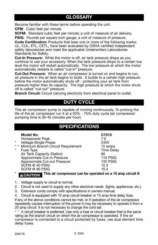
GLOSSARYBecome familiar with these terms before operating the unit.CFM: Cubic feet per minute.SCFM: Standard cubic feet per minute; a unit of measure of air delivery.PSIG: Pounds per square inch gauge; a unit of measure of pressure.Code Certification: Products that bear one or more of the following marks:UL, CUL, ETL, CETL, have been evaluated by OSHA certified independentsafety laboratories and meet the applicable Underwriters LaboratoriesStandards for Safety.Cut-In Pressure: While the motor is off, air tank pressure drops as youcontinue to use your accessory. When the tank pressure drops to a certain lowlevel the motor will restart automatically. The low pressure at which the motorautomatically restarts is called “cut-in” pressure.Cut-Out Pressure: When an air compressor is turned on and begins to run,air pressure in the air tank begins to build. It builds to a certain high pressurebefore the motor automatically shuts off - protecting your air tank frompressure higher than its capacity. The high pressure at which the motor shutsoff is called “cut-out” pressure.Branch Circuit: Circuit carrying electricity from electrical panel to outlet.
DUTY CYCLE
This air compressor pump is capable of running continuously. To prolong thelife of the air compressor run it at a 50% - 75% duty cycle (air compressorpumping time is 30-45 minutes per hour).
SPECIFICATIONS
Model No. C7510Horsepower Peak 7.0
* Voltage-Single Phase 240V* * Minimum Branch Circuit Requirement 15 amps* Fuse Type Time Delay
Air Tank Capacity (Gallon) 60Approximate Cut-in Pressure 110 PSIGApproximate Cut-out Pressure 135 PSIGSCFM @ 40 PSIG 12.3SCFM @ 90 PSIG 10.4
* This air compressor can be operated on a 15 amp circuit if:
1. Voltage supply to circuit is normal.2. Circuit is not used to supply any other electrical needs (lights, appliances, etc.)3. Extension cords comply with specifications in owners manual.4. Circuit is equipped with 15 amp circuit breaker or 15 amp time delay fuse.If any of the above conditions cannot be met, or if operation of the air compressorrepeatedly causes interruption of the power it may be necessary to operate it from a20 amp circuit. It is not necessary to change the cord set.* * A circuit breaker is preferred. Use only a fuse or circuit breaker that is the samerating as the branch circuit on which the air compressor is operated. If the aircompressor is connected to a circuit protected by fuses, use dual element timedelay fuses.

9- ENG D28176
ACCESSORIESAccessories for this unit are available at the store the unit was purchased.
ASSEMBLYTools Required for Assembly1 - 9/16” socket or open end wrench1 - electric drill
Unpacking1. Remove all packaging.
It may be necessary to brace or support one side of theoutfit when removing the pallet because the air
compressor will have a tendency to tip.
2. Remove and discard the (4) screws and washers holding the compressorto the pallet.
3. With the help of another person carefully remove air compressor frompallet and place on a level surface.
To Add Oil To PumpCompressors are shipped without oil in the crankcase. Asmall amount of oil may be present in the pump upon
receipt of the air compressor. This is due to plant testing and does notmean the pump contains oil. Do not attempt to operate this aircompressor without first adding oil to the crankcase. Serious damage canresult from even limited operation unless filled with oil and broken incorrectly. Make sure to closely follow initial start-up procedures.
Multi-Viscosity motor oils, like 10W 30, should not be usedin an air compressor. They leave carbon deposits on
critical components, thus reducing performance and compressor life. Useair compressor oil only.NOTE: Oil is included with some units. If oil is not included, use an oilspecifically formulated for use in an air compressor, such as Porter-Cable PAS1air compressor oil. Oil may be found at the store where the air compressor waspurchased.1. Place unit on a level surface.
Drain tank to release air pressure before removing the oilfill cap or oil drain plug.
2. Remove oil fill plug (A) and slowlyadd compressor oil until it reachesthe middle of the sight glass (B).NOTE: When filling the crankcase,the oil flows very slowly into thepump. If the oil is added too quickly,it will overflow and appear to be full.NOTE: Crankcase oil capacity isapproximately 29 fluid ounces.
3. Replace oil fill plug.
A
B

10- ENGD28176
Anchoring of the Air CompressorExcessive Vibration can weaken the air tank and cause anexplosion. The compressor must be properly mounted.
The air compressor MUST be bolted to a solid, level surface.Hardware needed:
4 - Concrete anchors (not supplied)4 - 3/8” Lag screw to fit concrete anchors
(not supplied)4 - 5/8” Washer (found in parts bag)
shims (if needed)1. Place the air compressor on on a solid, level surface.2. Mark the surface using the holes in the air compressor feet as a template.3. Drill holes in the surface for the concrete anchors. Install concrete anchors.
4. Line-up holes in surface with holes in air compressor feet.5. Place the (4) washers (supplied) between the floor and air compressor feet.
If needed, solid shims may be placed between the washers and floor toevenly distribute weight on all four feet.
6. Place the (4) 3/8” lag screws through the air compressor feet, washers,shims, and into the anchors.
7. Torque 3/8” lag screws to 7-10 ft.-lbs.
Location of the Air Compressor• Locate the air compressor in a clean, dry, and well ventilated area. • Locate the air compressor at least 12" away from the wall or other
obstructions that will interfere with the flow of air. • Locate the air compressor as close to the main power supply as possible
to avoid using long lengths of electrical wiring. NOTE: Long lengths ofelectrical wiring could cause power loss to the motor.
• The air filter must be kept clear of obstructions which could reduce air flowto the air compressor.
HOW TO SET UP YOUR UNIT
3/8” LagScrew (not supplied)
5/8” Washer(supplied)
Shim UnderWasher(not supplied)
Concrete Anchor(not supplied)
Surface Line
INSTALLATION

11- ENG D28176
Wiring InstructionsRISK OF ELECTRICAL SHOCK. Improper electricalgrounding can result in electrical shock. The wiring
should be done by a qualified electrician to comply with national and localelectrical codes.A qualified electrician needs to knows the following before wiring:1. The amperage rating of the electrical box should be adequate. Refer to the
product specifications, found in the parts manual, for this information.2. The supply line should have the same electrical characteristics (voltage,
cycle, phase) as the motor. Refer to the motor nameplate, on side ofmotor, for this information.
NOTE: The wiring must be the same as the motor nameplate voltage plus orminus 10%. Refer to local codes for recommended wire sizes, correct wiresize, and maximum wire run; undersize wire causes high amp draw andoverheating to the motor.
Electrical wiring must be located away from hot surfacessuch as manifold assembly, compressor outlet tubes,
heads, or cylinders.
GROUNDING INSTRUCTIONS
This product should be connected to a metallic, permanent wiring system, oran equipment-grounding terminal or lead on the product and comply withnational and local electrical codes.Refer to the product specification found in the front of this manual for thevoltage and minimum branch circuit requirements.

12- ENGD28176
Air Distribution SystemPlastic or PVC pipe is not designed for use withcompressed air. Regardless of its indicated pressure
rating, plastic pipe can burst from air pressure. Use only metal pipe for airdistribution lines.The next figure represents a typical air distribution system. The following aretips to remember when setting up the air compressor’s air distribution system.● Use pipe that is the same size as the air tank outlet. Piping that is too
small will restrict the flow of air. ● If piping is over 100 feet long, use the next larger size. ● Bury underground lines below the frost line and avoid pockets where
condensation can gather and freeze. Apply pressure before undergroundlines are covered to make sure all pipe joints are free of leaks.
● A flexible coupling is recommended to be installed between the airdischarge outlet and main air distribution line to allow for vibration.
● A separate regulator is recommended to control the air pressure. Airpressure from the tank is usually to high for individual air driven tools.
DRAINTRAP
DRAINTRAPS
DRAINLEGS
MOISTURESEPARATORAND TRAP
DIRTLEG
DIRTLEG
LUBRICATOR
REGULATOR
FILTER
AIR DISCHARGEVALVE
LUBRICATOR
MAIN DISTRIBUTION AIR LINESSlope pipe in direction of air flow.Water condensate flows along bottom of pipe to drain legs, preventing it from entering feeder lines.
REGULATOR
FLEXIBLECOUPLING
DRAIN COCKVALVE
TYPICAL COMPRESSEDAIR DISTRIBUTION SYSTEM
AIR USAGELINES
AIRCOMPRESSOR

13- ENG D28176
Description of OperationBecome familiar with these controls before operating the unit.
On/Auto/Off Switch: Turn this switchON to provide automatic power tothe pressure switch and OFF toremove power at the end of eachuse.
Pressure Switch: The pressureswitch automatically starts the motorwhen the air tank pressure dropsbelow the factory set “cut-in”pressure. It stops the motor when theair tank pressure reaches the factoryset “cut-out” pressure.
Safety Valve: If the pressure switchdoes not shut off the air compressorat its “cut-out” pressure setting, thesafety valve will protect against highpressure by “popping out” at its factory set pressure (slightly higher than thepressure switch “cut-out” setting).
Tank Pressure Gauge: The tank pressure gauge indicates the reserve airpressure in the tank.
Globe Valve (sold separately): Opens and closes air discharge valve. Turnknob counter-clockwise to open and clockwise to close.
Drain Valve: The drain valve is located at thebase of the air tank and is used to draincondensation at the end of each use.Air Compressor Pump (not shown):Compresses air into the air tank. Working air isnot available until the compressor has raised theair tank pressure above that required at the air outlet.
Check Valve: When the air compressor is operating,the check valve is “open”, allowing compressed air toenter the air tank. When the air compressor reaches“cut-out” pressure, the check valve “closes”, allowingair pressure to remain inside the air tank.
OPERATIONKnow Your Air CompressorREAD THIS OWNER’S MANUAL AND SAFETY RULES BEFORE OPERATINGYOUR UNIT. Compare the illustrations with your unit to familiarize yourself withthe location of various controls and adjustments. Save this manual for futurereference.
Globe Valve
TankPressure
Gauge
Safety Valve
On/Auto/OffSwitch
Pressure Switch
Drain Valve
Check Valve

14- ENGD28176
Pressure Release Valve: The pressure releasevalve, located on the side of the pressure switch, isdesigned to automatically release compressed airfrom the compressor head and the outlet tube whenthe air compressor reaches “cut-out” pressure or isshut off. The pressure release valve allows the motorto restart freely. When the motor stops running, airwill be heard escaping from this valve for a fewseconds. No air should be heard leaking when the motor is running, orcontinuous leaking after unit reaches “cut-out” pressure.
Air Intake Filter (not shown) This filter is designed to clean air coming intothe pump. This filter must always be clean and ventilation openings free fromobstructions. See "Maintenance".
How to Use Your UnitHow to Stop:
1. Set the On/Auto/Off lever to “OFF”.
PressureRelease
Valve
Before Starting
Break-in ProcedureSerious damage may result if the following break-ininstructions are not closely followed.
This procedure is required before the air compressor is put into service andwhen the check valve or a complete compressor pump has been replaced.
1. Make sure the On/Auto/Off lever is in the "OFF" position.
2. Recheck all wiring. Make sure wires are secure at all terminals connections.Make sure all contacts move freely and are not obstructed.
3. Open the globe valve fully to permit air to escape and prevent air pressurebuild up in the air tank during the break-in period.
4. Move the On/Auto/Off lever to "ON/AUTO" position. The compressor willstart.
5. Run the compressor for 20 minutes. Make sure the globe valve is openand there is minimal air pressure build-up in tank.
6. Check all air line fittings and connections/piping for air leaks by applying asoap solution. Correct if necessary. NOTE: Minor leaks can cause the aircompressor to overwork, resulting in premature breakdown or inadequateperformance.
7. Check for excessive vibration. Readjust or shim air compressor feet, ifnecessary.
8. After 20 minutes, close the globe valve.The air receiver will fill to “cut-out”pressure and the motor will stop.

15- ENG D28176
How to Start1. Turn the On/Auto/Off lever to “AUTO” and allow tank pressure to build.
Motor will stop when tank pressure reaches “cut-out” pressure.
2. When the tank pressure reaches “cut-out” pressure open the globe valve.
IMPORTANT: When using regulator and other accessories refer to themanufacturers instructions.
NOTE: Always operate the air compressor in well-ventilated areas free ofgasoline or other combustible vapors. If the compressor is being used tooperate a sprayer, DO NOT place compressor near the spray area.
Before Each Start-Up:1. Place On/Auto/Off lever to “OFF”.
2. Close the globe valve.
3. Attach hose and accessories. NOTE: A regulator MUST be installed whenusing accessories rated at less than 110 PSI.
Too much air pressure causes a hazardous risk of bursting.Check the manufacturer’s maximum pressure rating for air
tools and accessories. The regulator outlet pressure must never exceed themaximum pressure rating.

16- ENGD28176
MAINTENANCE
Customer Responsibilities
Daily orafter eachuse
Beforeeachuse
●
●●
Every8hours
Every40hours
Every100hours
Yearly
●
●1
1- more frequent in dusty or humid conditions
Check Safety Valve
Drain Tank
Oil Leaks
Check OilChange Oil
Air Filter
NOTE: See “Operation” section for the location of controls.
To ensure efficient operation and longer life of the air compressor outfit, aroutine maintenance schedule should be prepared and followed. The followingroutine maintenance schedule is geared to an outfit in a normal workingenvironment operating on a daily basis. If necessary, the schedule should bemodified to suit the conditions under which your compressor is used. Themodifications will depend upon the hours of operation and the workingenvironment. Compressor outfits in an extremely dirty and/or hostileenvironment will require a greater frequency of all maintenance checks.
Unit cycles automatically when power is on. Whenperforming maintenance, you may be exposed to voltage
sources, compressed air, or moving parts. Personal injuries can occur.Before performing any maintenance or repair, disconnect power sourcefrom the compressor and bleed off all air pressure.
To Check Safety ValveIf the safety valve does not work properly, over-pressurization may occur, causing air tank rupture or an
explosion. 1. Before starting compressor, pull the ring on the safety valve to make sure
that the safety valve operates freely. If the valve is stuck or does notoperate smoothly, it must be replaced with the same type of valve.
Unusual Noiseand/or Vibration
Drive Belt-Condition
Motor Pulley/Flywheel alignmentAir compressor pump intakeand exhaust valvesInspect air lines andfittings for leaks
●
●
●
●
●
●
Head Bolts - Check the torques of the head bolts after the first five hours of operation.

17- ENG D28176
OilChecking1. The oil level should be to the middle
of the sight glass (C).2. If needed remove oil fill plug (A) and
slowly add oil until it reaches themiddle of the sight glass.
NOTE: Use an oil specifically formulatedfor use in an air compressor, such asPorter-Cable PAS1 air compressor oil.Oil may be found at the store where theair compressor was purchased.Changing
Drain tank to releaseair pressure before
removing the oil fill cap or oil drainplug.1. Remove the oil fill plug (A). 2. Remove the oil drain plug (B) and drain oil into a suitable container. 3. Replace the oil drain plug (B) and tighten securely 4. Slowly add compressor oil until it reaches the middle of the sight glass (C).
NOTE: When filling the crankcase, the oil flows very slowly into the pump.If the oil is added too quickly, it will overflow and appear to be full. NOTE:Crankcase oil capacity is approximately 29 fluid ounces (857,6 ml).
Overfilling with oil will cause premature compressorfailure. Do not overfill.
5. Replace oil fill plug (A) and tighten securely.
To Drain TankNOTE: Operation of the air compressor will cause condensation to build up inthe air tank. Always drain tank on a washable surface or into a suitablecontainer to prevent damaging or staining surfaces.1. Set the On/Auto/Off lever to “OFF”.2. Close the globe valve.3. Remove the air tool or accessory.4. Open the globe valve and allow the air to slowly bleed from the air tank
until tank pressure is approximately 20 psi. 5. Close the globe valve.6. Drain water from air tank by opening drain valve (counter-clockwise) on
bottom of tank.Water will condense in the air tank. If not drained, waterwill corrode and weaken the air tank causing a risk of airtank rupture.
7. After the water has been drained, close the drain valve (clockwise). The aircompressor can now be stored.
NOTE: If drain valve is plugged, release all air pressure. The valve can then beremoved, cleaned, then reinstalled.
C
B
A

18- ENGD28176
Air Filter - Inspection and ReplacementHot surfaces. Risk of burn. Compressor heads areexposed when filter cover is removed. Allow compressor
to cool prior to servicing.A dirty air filter will not allow the compressor to operate at full capacity. Keepthe air filter clean at all times. 1. Remove air filter(s).2. Remove the air filter cover (s).3. Remove the air filter(s) from filter cover(s).IMPORTANT: Do not operate the compressor with the air filter removed.4. Place new air filter into filter cover(s). Refer to the “Repair Parts” for the
correct part number.5. Replace air filter cover(s) and reassemble air filter(s) to pump.
Adjusting Belt Tension1. Slide motor into original position, line the motor up with the mark made
earlier on saddle.2. Tighten two outside motor mounting screws enough to hold the motor in
place for checking pulley and flywheel alignment.
Belt - Replacement(Refer to the Parts Manual for replacement belt part number.)
Serious injury or damage may occur if parts of the body orloose items get caught in moving parts. Never operate the
outfit with the belt guard removed. The belt guard should be removed onlywhen the AIR compressor power is disconnected.1. Turn air compressor off, lock out the power supply, and relieve all air
pressure from the air tank.2. Remove the belt guard.3. Mark pump position on saddle.4. Loosen the motor mounting screws and slide the motor toward the air
compressor.5. Remove the belt and replace with a new one.6. See the “Adjust Belt Tension” before tightening motor mounting screws.
Belt Guard – Removal1. Turn air compressor off, lock out
the power supply, and relieve allair pressure from the air tank.
2. Remove the six screws (A) fromthe belt guard. The belt guardcan now lifted up and away fromunit.
A
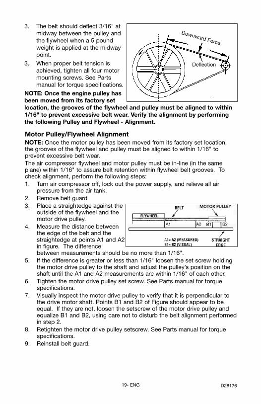
3. The belt should deflect 3/16" atmidway between the pulley andthe flywheel when a 5 poundweight is applied at the midwaypoint.
3. When proper belt tension isachieved, tighten all four motormounting screws. See Partsmanual for torque specifications.
NOTE: Once the engine pulley hasbeen moved from its factory setlocation, the grooves of the flywheel and pulley must be aligned to within1/16" to prevent excessive belt wear. Verify the alignment by performingthe following Pulley and Flywheel - Alignment.
19- ENG D28176
Motor Pulley/Flywheel AlignmentNOTE: Once the motor pulley has been moved from its factory set location,the grooves of the flywheel and pulley must be aligned to within 1/16" toprevent excessive belt wear.The air compressor flywheel and motor pulley must be in-line (in the sameplane) within 1/16" to assure belt retention within flywheel belt grooves. Tocheck alignment, perform the following steps:1. Turn air compressor off, lock out the power supply, and relieve all air
pressure from the air tank.2. Remove belt guard3. Place a straightedge against the
outside of the flywheel and themotor drive pulley.
4. Measure the distance betweenthe edge of the belt and thestraightedge at points A1 and A2in figure. The differencebetween measurements should be no more than 1/16".
5. If the difference is greater or less than 1/16" loosen the set screw holdingthe motor drive pulley to the shaft and adjust the pulley’s position on theshaft until the A1 and A2 measurements are within 1/16" of each other.
6. Tighten the motor drive pulley set screw. See Parts manual for torquespecifications.
7. Visually inspect the motor drive pulley to verify that it is perpendicular tothe drive motor shaft. Points B1 and B2 of Figure should appear to beequal. If they are not, loosen the setscrew of the motor drive pulley andequalize B1 and B2, using care not to disturb the belt alignment performedin step 2.
8. Retighten the motor drive pulley setscrew. See Parts manual for torquespecifications.
9. Reinstall belt guard.
Downward Force
Deflection

20- ENGD28176
Air Compressor Pump Intake and Exhaust ValvesOnce a year have a Trained Service Technician check the air compressor pumpintake and exhaust valves.
Inspect Air Lines and Fittings for Leaks1. Turn air compressor off, lock out the power supply, and relieve all air
pressure from the air tank.
2. Apply a soap solution to all air line fittings and connections/piping.
3. Correct any leaks found.
IMPORTANT: Even minor leaks can cause the air compressor to overwork,resulting in premature breakdown or inadequate performance.
Air compressor Head Bolts - Torquing The air compressor pump head bolts should be kept properly torqued. Checkthe torques of the head bolts after the first five hours of operation. Retighten ifnecessary. See Parts manual for torque specifications.

21- ENG D28176
SERVICE AND ADJUSTMENTS
Unit cycles automatically when power is on. When doingMaintenance, you may be exposed to voltage sources,
compressed air or moving parts. Personal injuries can occur. Beforeperforming any Maintenance or repair, unplug the compressor and bleedoff all air pressure.
ALL MAINTENANCE AND REPAIR OPERATIONS NOT LISTED MUST BEPERFORMED BY TRAINED SERVICE TECHNICIAN.
Before servicing:• Unplug or disconnect electrical supply to the air compressor.• Bleed tank of pressure.• Allow the air compressor to cool.
To Replace or Clean Check Valve 1. Release all air pressure from air tank. See “To Drain Tank” in the
Maintenance section.2. Turn air compressor off, lock out the power supply, and relieve all air
pressure from the air tank.3. Using an adjustable wrench loosen outlet tube nut at air tank and pump.
Carefully move outlet tube away from check valve.4. Using an adjustable wrench loosen pressure relief tube nut at air tank and
pressure switch. Carefully move pressure relief tube away from checkvalve.
5. Unscrew the check valve (turn counterclockwise) using a 7/8” open endwrench. Note the orientation for reassembly.
6. Using a screwdriver, carefully pushthe valve disc up and down. NOTE:The valve disc should move freelyup and down on a spring whichholds the valve disc in the closedposition, if not the check valveneeds to be cleaned or replaced.
7. Clean or replace the check valve. Asolvent, such as paint or varnishremover can be used to clean thecheck valve.
8. Apply sealant to the check valve threads. Reinstall the check valve (turnclockwise).
9. Replace the pressure release tube. Tighten nuts.10. Replace the outlet tube and tighten nuts.11. Perform the Break-in Procedure. See “Break-in Procedure” in the
Operation section.
In closed positiondisc is visible.
In openpositionnothing isvisible.
Screwdriver
22- ENGD28176
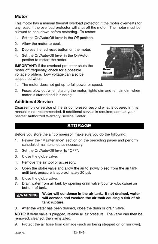
MotorThis motor has a manual thermal overload protector. If the motor overheats forany reason, the overload protector will shut off the motor. The motor must beallowed to cool down before restarting. To restart:
1. Set the On/Auto/Off lever in the Off position.
2. Allow the motor to cool.
3. Depress the red reset button on the motor.
4. Set the On/Auto/Off lever in the On/Autopostion to restart the motor.
IMPORTANT: If the overload protector shuts themotor off frequently, check for a possiblevoltage problem. Low voltage can also besuspected when:
1. The motor does not get up to full power or speed.
2. Fuses blow out when starting the motor; lights dim and remain dim whenmotor is started and is running.
Additional ServiceDisassembly or service of the air compressor beyond what is covered in thismanual is not recommended. If additional service is required, contact yournearest Authorized Warranty Service Center.
ResetButton
STORAGE
Before you store the air compressor, make sure you do the following:
1. Review the "Maintenance" section on the preceding pages and performscheduled maintenance as necessary.
2. Set the On/Auto/Off lever to "OFF".
3. Close the globe valve.
4. Remove the air tool or accessory.
5. Open the globe valve and allow the air to slowly bleed from the air tankuntil tank pressure is approximately 20 psi.
6. Close the globe valve.7. Drain water from air tank by opening drain valve (counter-clockwise) on
bottom of tank.
Water will condense in the air tank. If not drained, waterwill corrode and weaken the air tank causing a risk of airtank rupture.
8. After the water has been drained, close the drain or drain valve.
NOTE: If drain valve is plugged, release all air pressure. The valve can then beremoved, cleaned, then reinstalled.
9. Protect the air hose from damage (such as being stepped on or run over).

23- ENG D28176
TROUBLESHOOTINGPerforming repairs may expose voltage sources, movingparts or compressed air sources, moving parts or
compressd air sources. Personal injury may occur. Prior to attempting anyrepairs, unplug the air compressor and bleed off all air tank air pressure.
PROBLEM CAUSE CORRECTION
Pressure switch does notshut off motor whencompressor reaches "cut-out" pressure.
Pressure switch "cut-out"too high.
Set On/Auto/Off lever to the"OFF" position, if the unitdoes not shut off contact aTrained Service Technician.
Contact a Trained ServiceTechnician.
Excessive tankpressure -safety valvepops off.
Tube fittings are not tightenough.
Tighten fittings where air canbe heard escaping. Checkfittings with soapy watersolution. DO NOTOVERTIGHTEN.
Air leaks atfittings.
Air leaks atpressure switchrelease valve. (if equipped)
Defective pressure switchrelease valve.
Contact a Trained ServiceTechnician.
Air leaks in airtank or at airtank welds.
Defective air tank. Air tank must be replaced.Do not repair the leak.
Do not drillinto, weld
or otherwise modify airtank or it will weaken. Thetank can rupture orexplode.
Air leaksbetween headand valve plate.
Leaking seal. Contact a Trained ServiceTechnician.
Air leaks at orinside checkvalve
Check valve seat damaged. A defective check valveresults in a constant air leakat the pressure release valvewhen there is pressure in thetank and the compressor isshut off. Replace checkvalve. Refer the "To Replaceor Clean Check Valve" in the"Operation" section.

24- ENGD28176
PROBLEM CAUSE CORRECTION
Compressor isnot supplyingenough air tooperateaccessories.
Prolonged excessive use ofair.Compressor is not largeenough for air requirement.
Hole in hose.
Check valve restricted.
Air leaks.
Restricted air intake filter.
Decrease amount of air usage.
Check the accessory airrequirement. If it is higher thanthe SCFM or pressure suppliedby your air compressor, youneed a larger compressor.Check and replace if required.
Remove and clean, or replace.
Tighten fittings.
Clean or replace air intakefilter. Do not operate the aircompressor with the filterremoved. Refer to the "AirFilter" paragraph in the"Maintenance " section.
Pressure readingon the regulatedpressure gauge(if equipped)drops when anaccessory isused.
It is normal for "some"pressure drop to occur.
If there is an excessive amountof pressure drop when theaccessory is used, adjust theregulator as instructed in theOperation section.NOTE: Adjust the regulatedpressure under flow conditions(while accesory is being used).
Possible defect in safetyvalve.
Operate safety valve manuallyby pulling on ring. If valve stillleaks, it should be replaced.
Air leak fromsafety valve.
Clean or replace. See Air Filterparagraph in the Maintenancesection.
Dirty air filter.Restricted airintake.
Check belt tension, seeAdjusting Belt Tension in theMaintenance section.
Loose belt.

25- ENG D28176
PROBLEM CAUSE CORRECTIONMotor will notrun.
Fuse blown, circuit breakertripped.
1. Check fuse box for blownfuse and replace asnecessary. Reset circuitbreaker. Do not use a fuseor circuit breaker withhigher rating than thatspecified for yourparticular branch circuit.
2. Check for proper fuse. Youshould use a time delayfuse.
3. Check for low voltageconditions and/or properextension cord.
4. Disconnect the otherelectrical appliances fromcircuit or operate thecompressor on its ownbranch circuit.
Motor overload protectionswitch has tripped.
Let motor cool off andoverload switch willautomatically reset.
Tank pressure exceedspressure switch "cut-in"pressure.
Motor will start automaticallywhen tank pressure dropsbelow "cut-in" pressure ofpressure switch.
Loose electricalconnections.
Check wiring connectioninside pressure switch andterminal box area.
Have checked by a TrainedService Technician.
Check valve stuck open. Remove and clean, or replace.
Possible defective motoror starting capacitor.
Have checked by a TrainedService Technician. Do notoperate the compressor in thepaint spray area. Seeflammable vapor warning.
Paint spray on internalmotor parts.
Bleed the line by pushing thelever on the pressure switch tothe "off" position; if the valvedoes not open, replace switch.
Pressure release valve onpressure switch has notunloaded head pressure.
26- ENGD28176
PROBLEM CAUSE CORRECTION
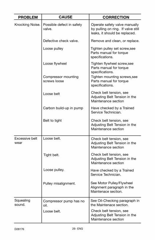
Knocking Noise. Possible defect in safetyvalve.
Operate safety valve manuallyby pulling on ring. If valve stillleaks, it should be replaced.
Loose pulley Tighten pulley set screw,seeParts manual for torquespecifications.
Compressor mountingscrews loose
Tighten mounting screws,seeParts manual for torquespecifications.
Loose flywheel Tighten flywheel screw,seeParts manual for torquespecifications.
Loose belt Check belt tension, seeAdjusting Belt Tension in theMaintenance section
Carbon build-up in pump Have checked by a TrainedService Technician.
Belt to tight Check belt tension, seeAdjusting Belt Tension in theMaintenance section
Excessive beltwear
Loose belt.
Tight belt.
Loose pulley. Have checked by a TrainedService Technician.
Pulley misalignment. See Motor Pulley/FlywheelAlignment paragraph in theMaintenace section.
Squealingsound.
Loose belt.
Compressor pump has nooil.
See Oil-Checking paragraph inthe Maintenace section.
Check belt tension, seeAdjusting Belt Tension in theMaintenance section
Check belt tension, seeAdjusting Belt Tension in theMaintenance section
Check belt tension, seeAdjusting Belt Tension in theMaintenance section
Defective check valve. Remove and clean, or replace.

27- ENG D28176
NOTES

28- ENGD28176
LIMITED WARRANTYPORTER-CABLE CORPORATION warrants to the original purchaser that all products covered under thiswarranty are free from defects in material and workmanship. Products covered under this warranty include aircompressors, air tools, service parts, pressure washers, and generators, which have the following warrantyperiods:
3 YEARS - Limited warranty on 2-stage oil-free air compressor pumps that operate at 1725 RPM.2 YEARS - Limited warranty on oil-lubricated air compressor pumps. 1 YEAR - Limited warranty on all other air compressor components.2 YEARS - Limited warranty on electric generator alternators.1 YEAR - Limited warranty on other generator components.2 YEARS - Limited warranty on pneumatic air tools as described in Porter-Cable general catalog.1 YEAR - Limited warranty on pressure washers used in consumer applications (i.e. personal residentialhousehold usage only).90 DAY - Pressure washers used for commercial applications (income producing) and service parts.1 YEAR - Limited warranty on all accessories.
Porter-Cable will repair or replace, at Porter-Cable's option, products or components which have failedwithin the warranty period. Service will be scheduled according to the normal work flow and businesshours at the service center location, and the availability of replacement parts. All decisions of Porter-Cable Corporation with regard to this limited warranty shall be final.This warranty gives you specific legal rights, and you may also have other rights which vary from state tostate.RESPONSIBILITY OF ORIGINAL PURCHASER (initial User):• To process a warranty claim on this product, DO NOT return it to the retailer. The product must be
evaluated by an Porter-Cable Authorized Warranty Service Center. For the location of the nearest Porter-Cable Authorized Warranty Service Center call 1-888-559-8550, 24 hours a day, 7 days a week.
• Retain original cash register sales receipt as proof of purchase for warranty work.• Use reasonable care in the operation and maintenance of the product as described in the Owners
Manual(s).• Deliver or ship the product to the nearest Porter-Cable Authorized Warranty Service Center. Freight costs,
if any, must be paid by the purchaser.• Air compressors with 60 and 80 gallon tanks will be inspected at the site of installation. Contact the
nearest Porter-Cable Authorized Warranty Service Center that provides on-site service calls, for servicecall arrangements.
• If the purchaser does not receive satisfactory results from the Porter-Cable Authorized Warranty ServiceCenter, the purchaser should contact Porter-Cable.
THIS WARRANTY DOES NOT COVER:• Merchandise sold as reconditioned, used as rental equipment, and floor or display models.• Merchandise that has become damaged or inoperative because of ordinary wear, misuse*, cold, heat, rain,
excessive humidity, freeze damage, use of improper chemicals, negligence, accident, failure to operatethe product in accordance with the instructions provided in the Owners Manual(s) supplied with theproduct, improper maintenance, the use of accessories or attachments not recommended by Porter-Cable, or unauthorized repair or alterations. * An air compressor that pumps air more than 50% during a one hour period is considered misusebecause the air compressor is undersized for the required air demand.
• Repair and transportation costs of merchandise determined not to be defective.• Costs associated with assembly, required oil, adjustments or other installation and start-up costs.• Expendable parts or accessories supplied with the product which are expected to become inoperative or
unuseable after a reasonable period of use, including but not limited to sanding disks or pads, saw andshear blades, grinding stones, springs, chisels, nozzles, o-rings, air jets, washers and similar accessories.
• Merchandise sold by Porter-Cable which has been manufactured by and identified as the product ofanother company, such as gasoline engines. The product manufacturer's warranty, if any, will apply.
• ANY INCIDENTAL, INDIRECT OR CONSEQUENTIAL LOSS, DAMAGE, OR EXPENSE THAT MAYRESULT FROM ANY DEFECT, FAILURE OR MALFUNCTION OF THE PRODUCT IS NOT COVERED BYTHIS WARRANTY. Some states do not allow the exclusion or limitation of incidental or consequentialdamages, so the above limitation or exclusion may not apply to you.
• IMPLIED WARRANTIES, INCLUDING THOSE OF MERCHANTABILITY OR FITNESS FOR APARTICULAR PURPOSE, ARE LIMITED TO ONE YEAR FROM THE DATE OF ORIGINAL PURCHASE.Some states do not allow limitations on how long an implied warranty lasts, so the above limitations maynot apply to you.
®
Porter-Cable CorporationJackson, TN USA1-888-559-8550