Embed Size (px)
Citation preview
A652–01–880 Issue P Original
Instruction ManualRV3, RV5, RV8 and RV12 Rotary Vane Pumps
A 65X-YY-ZZZ
Pump Type Variant Motor DescriptionX YY ZZZ
2 = RV3 01 to 99 903 = 220-240V, 50/60Hz, Single phase3 = RV5 904 = 100/200V, 50/60Hz, Single phase4 = RV8 905 = 200-230/380-460V, 50/60Hz, Three phase5 = RV12 906 = 110-115/120V 50/60Hz, Single phase
965 = NEMA Bareshaft970 = ISO Bareshaft


RV3, RV5, RV8 and RV12 Rotary Vane Pumps
PAGEi
Ipsi
tech
820
7(E)
–05
CONTENTS
Section Page
1 INTRODUCTION 11.1 Scope and definitions 11.2 ATEX directive implications 21.3 Description 41.4 Performance modes and controls 41.4.1 Mode selector 41.4.2 Gas-ballast control 51.5 Construction 5
2 TECHNICAL DATA 72.1 Operating and storage conditions 72.2 Performance 72.2.1 General 72.2.2 Performance characteristics 112.3 Mechanical data 122.4 Noise and vibration data 122.5 Lubrication data 122.6 Electrical data: single-phase pumps 142.7 Electrical data: three-phase pumps 15
3 INSTALLATION 173.1 Safety 173.2 System design considerations 173.3 Unpack and inspect 183.4 Locate the pump 183.5 Fill the pump with oil 183.6 Fit the motor (bareshaft pumps only) 193.7 Electrical installation: single-phase pumps 193.7.1 Check and configure the motor 193.7.2 Connect the pump to your electrical supply 193.7.3 Check the direction of rotation 203.8 Electrical installation: three-phase pumps 223.8.1 Check and configure the motor 223.8.2 Connect the pump to your electrical supply 223.8.3 Check the direction of rotation 243.9 Inlet and outlet connections 243.10 Leak-test the system 25
4 OPERATION 274.1 ATEX directive implications 274.1.1 Introduction 274.1.2 Flammable/pyrophoric materials 274.1.3 Gas purges 284.2 How to use the pump controls 284.2.1 Introduction 284.2.2 Mode selector 294.2.3 Gas-ballast control 294.3 Start-up procedure 304.4 To achieve ultimate vacuum 304.5 To pump condensable vapours 314.6 To decontaminate the oil 31
Issue P i Jul 05

RV3, RV5, RV8 and RV12 Rotary Vane Pumps
PAGEii
Section Page
4.7 Unattended operation 314.8 Shut-down 32
5 MAINTENANCE 335.1 Safety information 335.2 Maintenance plan 345.3 Check the oil-level 345.4 Replace the oil 355.5 Inspect and clean the inlet-filter 355.6 Inspect and clean the gas-ballast control 365.7 Clean the oil-level sight-glass 375.8 Clean the motor fan-cover and enclosure 385.9 Clean and overhaul the pump 385.10 Fit new blades 385.11 Test the motor condition 385.12 Fault-finding 385.12.1 Introduction 385.12.2 The pump has failed to start 385.12.3 The pump has failed to achieve the specified performance
(has failed to reach ultimate vacuum) 395.12.4 The pump is noisy 395.12.5 The pump surface temperature is above 100 oC 395.12.6 The vacuum is not fully maintained after the pump is switched off 395.12.7 The pumping speed is poor 405.12.8 There is an external oil leak 40
6 STORAGE AND DISPOSAL 416.1 Storage 416.2 Disposal 41
7 SERVICE AND SPARES 437.1 Introduction 437.2 Service 437.3 Spares 437.4 Accessories 457.4.1 Introduction 457.4.2 Inlet catchpot 457.4.3 Inlet dust filter 457.4.4 Inlet desiccant trap 467.4.5 Inlet chemical trap 467.4.6 Foreline trap 467.4.7 Outlet mist filter 467.4.8 Gas-ballast adaptor 467.4.9 Gravity oil drain kit 467.4.10 Oil drain-extension 467.4.11 Exhaust nozzle kit 467.4.12 Vibration isolators 467.4.13 Solenoid operated gas-ballast valve 467.4.14 Solenoid operated pipeline valve 46
Issue P ii Jul 05
RV3, RV5, RV8 and RV12 Rotary Vane Pumps
PAGEiii
Section Page
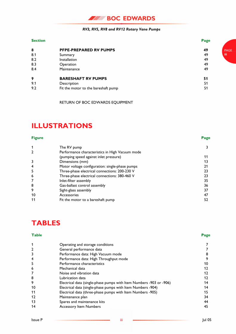
8 PFPE-PREPARED RV PUMPS 498.1 Summary 498.2 Installation 498.3 Operation 498.4 Maintenance 49
9 BARESHAFT RV PUMPS 519.1 Description 519.2 Fit the motor to the bareshaft pump 51
RETURN OF BOC EDWARDS EQUIPMENT
ILLUSTRATIONS
Figure Page
1 The RV pump 32 Performance characteristics in High Vacuum mode
(pumping speed against inlet pressure) 113 Dimensions (mm) 134 Motor voltage configuration: single-phase pumps 215 Three-phase electrical connections: 200-230 V 236 Three-phase electrical connections: 380-460 V 237 Inlet-filter assembly 358 Gas-ballast control assembly 369 Sight-glass assembly 3710 Accessories 4711 Fit the motor to a bareshaft pump 52
TABLES
Table Page
1 Operating and storage conditions 72 General performance data 73 Performance data: High Vacuum mode 84 Performance data: High Throughput mode 95 Performance characteristics 106 Mechanical data 127 Noise and vibration data 128 Lubrication data 129 Electrical data (single-phase pumps with Item Numbers -903 or -906) 1410 Electrical data (single-phase pumps with Item Numbers -904) 1411 Electrical data (three-phase pumps with Item Numbers -905) 1512 Maintenance plan 3413 Spares and maintenance kits 4414 Accessory Item Numbers 45
Issue P iii Jul 05

RV3, RV5, RV8 and RV12 Rotary Vane Pumps
PAGEiv
Associated publications
Publication title Publication NumberVacuum pump and vacuum system safety P300–20–000
Issue P iv Jul 05

RV3, RV5, RV8 and RV12 Rotary Vane Pumps
INT
RO
DU
CT
ION
PAGE1
1 INTRODUCTION
1.1 Scope and definitions
This manual provides installation, operation and maintenance instructions for the BOC Edwards RV3,RV5, RV8 and RV12 Rotary Vane Pumps. You must use your pump as specified in this manual.
Read this manual before you install and operate your pump. Important safety information is highlightedas WARNING and CAUTION instructions; you must obey these instructions. The use of WARNINGSand CAUTIONS is defined below.
The units used throughout this manual conform to the SI international system of units of measurement
In accordance with the recommendations of IEC1010, the following warning labels are on the pump:
Warning – refer to accompanying documentation.
Warning – risk of electric shock.
Warning – hot surfaces.
WARNING
Warnings are given where failure to observe the instruction could result in injury or death to people.
CAUTION
Cautions are given where failure to observe the instruction could result in damage to the equipment, associated equipment and process.
Issue P 1 Jul 05

RV3, RV5, RV8 and RV12 Rotary Vane Pumps
INT
RO
DU
CT
ION
PAGE2
1.2 ATEX directive implications
• This equipment is designed to meet the requirements of Group II Category 3 equipment inaccordance with Directive 94/9/EC of the European Parliament and the Council of 23rd March 1994on the approximation of the laws of the Member States concerning equipment and protectivesystems intended for use in potentially explosive atmospheres. (The ATEX Directive).
The ATEX Category 3 applies in respect of potential ignition sources internal to the equipment. AnATEX Category has not been assigned in respect of potential ignition sources on the outside of theequipment as the equipment has not been designed for use where there is an external potentiallyexplosive atmosphere.
There is no potential source of ignition within the pump during normal operation but there may bepotential sources of ignition under conditions of predicted and rare malfunction as defined in theDirective. Accordingly, although the pump is designed to pump flammable materials and mixtures,operating procedures should ensure that under all normal and reasonably predicted conditions,these materials and mixtures are not within explosive limits. Category 3 is considered appropriatefor the avoidance of ignition in the case of a rare malfunction which allows flammable materials ormixtures to pass through the pump while within their explosive limits.
• When flammable or pyrophoric materials are present within the equipment you must:
• Not allow air to enter the equipment.
• Ensure that the system is leak tight.
• Use an inert gas purge (for example, a nitrogen purge) to dilute any flammable gases orvapours entering the pump inlet, and/or use an inert gas purge to reduce the concentrationof flammable gases or vapours in the pump and in the exhaust pipeline to less than one quarterof the gases' published lower explosive limits (LEL).
• For further information, please contact BOC Edwards: refer to the Addresses page at the end ofthis manual for details of your nearest BOC Edwards company.
Issue P 2 Jul 05

RV3, RV5, RV8 and RV12 Rotary Vane Pumps
INT
RO
DU
CT
ION
PAGE3
Figure 1 – The RV pump
1. Electrical inlet-connector2. Voltage indicator3. Lifting handle *4. NW25 inlet-port5. Gas-ballast control6. Oil filler-plug7. NW25 outlet-port
8. Oil-level sight-glass9. Oil drain-plug10. Rubber feet (4 off)11. Mode selector12. On-off switch †
13. Motor fan-cover14. Correct direction of rotation
* RV3 and RV5 pumps only; a lifting bracket is fitted to RV8 and RV12 pumps.† Single-phase pumps only.
Note: Single-phase RV3/RV5 pump shown.
Issue P 3 Jul 05

RV3, RV5, RV8 and RV12 Rotary Vane Pumps
INT
RO
DU
CT
ION
PAGE4
1.3 Description
The BOC Edwards RV rotary vane pump is shown in Figure 1. Refer to Figure 1 for item numbers inbrackets in the following descriptions. The RV pumps are two-stage, oil-sealed, sliding-vane vacuumpumps. The pump has NW25 inlet (4) and outlet (7) ports, a gas-ballast control (5) and a mode selector(11). When the pump is switched off, an inlet-valve seals the inlet and prevents the suck-back of air andoil into the vacuum system.
The RV3 and RV5 pumps have a retractable lifting handle (3). The RV8 and the RV12 pumps are fittedwith a lifting bracket for use with suitable lifting equipment.
An oil-pump delivers pressurised oil to the vacuum pumping mechanism in the RV pump. You can inspectthe level and condition of the oil in the oil-box through a sight-glass (8). Two oil filler-plugs (6) and an oildrain-plug (9) are provided on the oil-box.
The pump mechanism is driven directly by a single-phase or three-phase electric motor through a flexiblemotor-coupling. The motor is totally enclosed and is cooled by the motor cooling-fan which directs airalong the motor fins. The pumps are cooled by an additional fan attached to the motor-coupling.
Single-phase motors are fitted with an on/off switch (12) and a thermal overload device. When the motoris too hot, the thermal overload device switches off the pump. The thermal overload device has anautomatic reset; when the motor cools down, the device resets and (unless you have incorporatedsuitable control equipment which must be manually reset: see Sections 3.7.2 and 3.8.2), the motor willrestart.
The pump is mounted on a base plate on rubber feet (10). Details of suitable vibration isolators and otheraccessories are provided in Section 7.4.
Refer to Section 8 for additional information if your pump is PFPE-prepared.
1.4 Performance modes and controls
The pump has two controls: the mode selector (11) and the gas-ballast control (5). Six possiblecombinations of these controls allow for a wide choice of operating characteristics so you can optimisethe performance of the pump for a given application.
1.4.1 Mode selector
The mode selector has two positions; refer to Section 4.2 to select these positions. Throughout therest of this manual, the following convention is used:
• The High Vacuum mode is specified by the ! symbol.
• The High Throughput mode is specified by the ! symbol.
With the mode selector set to High Vacuum mode !, pressurised oil is fed to the low vacuum stage only.In this mode of operation, the pump provides the best possible ultimate vacuum.
With the mode selector set to High Throughput mode !, pressurised oil is fed to the high vacuum andlow vacuum stages. In this mode of operation, the pump can sustain long-term high inlet pressures.
Issue P 4 Jul 05

RV3, RV5, RV8 and RV12 Rotary Vane Pumps
INT
RO
DU
CT
ION
PAGE5
1.4.2 Gas-ballast control
To pump high vapour loads, gas-ballast is delivered into the pump to prevent condensation of the vapourcarried by the pumped gases.
Air can be introduced to the low vacuum stage through the gas-ballast valve. Alternatively, an inert gassuch as nitrogen can be supplied through a suitable external valve.
The gas-ballast control has three positions:
• Closed (position '0')
• Low flow (position 'I')
• High flow (position 'II').
1.5 Construction
The pump-shafts and rotors are made of high-grade cast-iron. The pump-body and oil-box are made fromcast-aluminium. All surfaces of the pump which are exposed to the pumped gases are free from copper,zinc and cadmium.
Other materials of construction include fluorocarbon elastomer, nitrile, silicon, chemically-resistantpolymers, nickel and stainless steel.
Issue P 5 Jul 05

RV3, RV5, RV8 and RV12 Rotary Vane Pumps
PAGE6
Issue P 6 Jul 05
This page intentionally blank.
RV3, RV5, RV8 and RV12 Rotary Vane Pumps
TE
CH
NIC
AL
DA
TA
PAGE7
2 TECHNICAL DATA
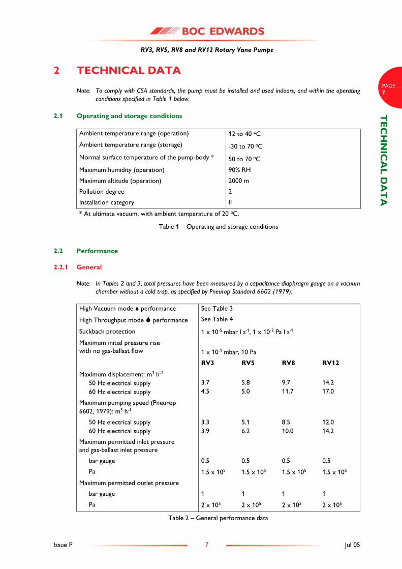
Note: To comply with CSA standards, the pump must be installed and used indoors, and within the operatingconditions specified in Table 1 below.
2.1 Operating and storage conditions
2.2 Performance
2.2.1 General
Note: In Tables 2 and 3, total pressures have been measured by a capacitance diaphragm gauge on a vacuumchamber without a cold trap, as specified by Pneurop Standard 6602 (1979).
Ambient temperature range (operation) 12 to 40 oC
Ambient temperature range (storage) -30 to 70 oC
Normal surface temperature of the pump-body * 50 to 70 oC
Maximum humidity (operation) 90% RH
Maximum altitude (operation) 2000 m
Pollution degree 2
Installation category II
* At ultimate vacuum, with ambient temperature of 20 oC.
Table 1 – Operating and storage conditions
High Vacuum mode ! performance See Table 3
High Throughput mode ! performance See Table 4
Suckback protection 1 x 10⁻⁵ mbar l s-1, 1 x 10⁻³ Pa l s-1
Maximum initial pressure risewith no gas-ballast flow 1 x 10⁻¹ mbar, 10 Pa
RV3 RV5 RV8 RV12
Maximum displacement: m3 h-1
50 Hz electrical supply60 Hz electrical supply
3.74.5
5.85.0
9.711.7
14.217.0
Maximum pumping speed (Pneurop6602, 1979): m3 h-1
50 Hz electrical supply60 Hz electrical supply
3.33.9
5.16.2
8.510.0
12.014.2
Maximum permitted inlet pressureand gas-ballast inlet pressure
bar gauge 0.5 0.5 0.5 0.5
Pa 1.5 x 10⁵ 1.5 x 10⁵ 1.5 x 10⁵ 1.5 x 10⁵
Maximum permitted outlet pressure
bar gauge 1 1 1 1
Pa 2 x 10⁵ 2 x 10⁵ 2 x 10⁵ 2 x 10⁵
Table 2 – General performance data
Issue P 7 Jul 05

RV3, RV5, RV8 and RV12 Rotary Vane Pumps
TE
CH
NIC
AL
DA
TA
PAGE8
Tab
le 3
– Pe
rfor
man
ce d
ata:
Hig
h V
acuu
m m
ode
HIG
H V
AC
UU
M M
OD
E !
eter
Uni
tsR
V3
RV
5R
V8
RV
12
1-p
has
e3-
ph
ase
1-ph
ase
3-ph
ase
1-ph
ase
3-ph
ase
1-ph
ase
3-ph
ase
alla
st c
ontr
ol c
lose
d (p
ositi
on '0
')
timat
e to
tal p
ress
ure
mba
r2
x 10
-32
x 10
-32
x 10
-32
x 10
-3
Pa2
x 10
-12
x 10
-12
x 10
-12
x 10
-1
alla
st c
ontr
ol lo
w fl
ow (
posi
tion
'I')
timat
e to
tal p
ress
ure
mba
r3
x 10
-23
x 10
-23
x 10
-23
x 10
-2
Pa3
33
3
s-ba
llast
flow
l min
-15
55
5
xim
um w
ater
vap
our
pum
ping
rat
ekg
h-1
0.06
0.04
0.06
0.04
0.06
0.04
0.06
0.04
xim
um w
ater
vap
our
inle
t pr
essu
rem
bar
2718
1611
107
75
Pa2.
7 x
103
1.8
x 10
31.
6 x
103
1.1
x 10
31
x 10
37
x 10
27
x 10
25
x 10
2
alla
st c
ontr
ol h
igh
flow
(po
sitio
n 'II
')
timat
e to
tal p
ress
ure
mba
r1.
2 x
10-1
1 x
10-1
6 x
10-2
6 x
10-2
Pa1.
2 x
101
1 x
101
66
s-ba
llast
flow
l min
-114
1416
16
xim
um w
ater
vap
our
pum
ping
rat
ekg
h-1
0.22
0.12
0.22
0.12
0.22
0.20
0.29
0.25
xim
um w
ater
vap
our
inle
t pr
essu
rem
bar
8054
5032
3834
3228
Pa8
x 10
35.
4 x
103
5 x
103
3.2
x 10
33.
8 x
103
3.4
x 10
33.
2 x
103
2.8
x 10
3
Issue P 8 Ju
Par
am
Gas
-b Ul
Gas
-b Ul
Ga
Ma
Ma
Gas
-b Ul
Ga
Ma
Ma
l 05

RV3, RV5, RV8 and RV12 Rotary Vane Pumps
TE
CH
NIC
AL
DA
TA
PAGE9
Tab
le 4
– Pe
rfor
man
ce d
ata:
Hig
h T
hrou
ghpu
t m
ode
HIG
H T
HR
OU
GH
PU
T M
OD
E !
Par
amet
erU
nits
RV
3R
V5
RV
8R
V12
1-p
hase
3-p
hase
1-p
hase
3-p
hase
1-p
hase
3-p
has
e1-
ph
ase
3-p
has
e
Gas
-bal
last
con
trol
clo
sed
(pos
ition
'0')
Ulti
mat
e to
tal p
ress
ure
mba
r3
x 10
-23
x 10
-23
x 10
-23
x 10
-2
Pa3
33
3
Gas
-bal
last
con
trol
low
flow
(po
sitio
n 'I'
)
Ulti
mat
e to
tal p
ress
ure
mba
r6
x 10
-26
x 10
-24
x 10
-24
x 10
-2
Pa6
64
4
Gas
-bal
last
flow
l min
-15
55
5
Max
imum
wat
er v
apou
r pu
mpi
ng r
ate
kg h
-10.
060.
040.
060.
040.
060.
040.
060.
04
Max
imum
wat
er v
apou
r in
let
pres
sure
mba
r27
1816
1110
77
5
Pa2.
7 x
103
1.8
x 10
31.
6 x
103
1.1
x 10
31
x 10
37
x 10
27
x 10
25
x 10
2
Gas
-bal
last
con
trol
hig
h flo
w (
posi
tion
'II')
Ulti
mat
e to
tal p
ress
ure
mba
r1.
2 x
10-1
1 x
10-1
6 x
10-2
6 x
10-2
Pa1.
2 x
101
1 x
101
66
Gas
-bal
last
flow
l min
-114
1416
16
Max
imum
wat
er v
apou
r pu
mpi
ng r
ate
kg h
-10.
220.
120.
220.
120.
220.
200.
290.
25
Max
imum
wat
er v
apou
r in
let
pres
sure
mba
r80
5450
3238
3432
28
Pa8
x 10
35.
4 x
103
5 x
103
3.2
x 10
33.
8 x
103
3.4
x 10
33.
2 x
103
2.8
x 10
3
Issue P 9 Ju
l 05
RV3, RV5, RV8 and RV12 Rotary Vane Pumps
TE
CH
NIC
AL
DA
TA
PAGE10
Tab
le 5
– Pe
rfor
man
ce c
hara
cter
istic
s
MO
DE
SE
LE
CT
OR
PO
SIT
ION
GA
S B
AL
LA
ST
CO
NT
RO
L
Clo
sed
(po
siti
on
'0')
Lo
w fl
ow
(p
osi
tio
n 'I
')H
igh
flo
w (
posi
tio
n 'II
')
Hig
h V
acuu
mm
ode !
Ulti
mat
e to
tal p
ress
ure
Ulti
mat
e to
tal p
ress
ure
Ulti
mat
e to
tal p
ress
ure
mba
rPa
mba
rPa
mba
rPa
2 x
10-3
2 x
10-1
3 x
10-2
31.
2 x
10-1
(RV
3)1.
0 x
10-1
(RV
5)6
x 10
-2 (
RV
8/12
)
1.2
x 10
1 (R
V3)
1.0
x 10
1 (R
V5)
6.0
(RV
8/12
)
Use
for
the
best
ultim
ate
pres
sure
Max
imum
wat
er v
apou
r pu
mpi
ng r
ate
Max
imum
wat
er v
apou
r pu
mpi
ng r
ate
1-ph
ase
pum
ps3-
phas
e pu
mps
1-ph
ase
pum
ps3-
phas
e pu
mps
0.06
kg
h-10.
04 k
g h-1
0.22
kg
h-1 (
RV
3/5/
8)0.
29 k
g h-1
(R
V12
)
0.12
kg
h-1 (
RV
3/5)
0.20
kg
h-1
(RV
8)0.
25 k
g h-1
(R
V12
)
Hig
h T
hrou
ghpu
tm
ode !
Ulti
mat
e to
tal p
ress
ure
Ulti
mat
e to
tal p
ress
ure
Ulti
mat
e to
tal p
ress
ure
mba
rPa
mba
rPa
mba
rPa
3 x
10-2
36
x 10
-2
(RV
3/5)
4 x
10-2
(RV
8/12
)6
(RV
3/5)
4 (R
V8/
12)
1.2
x 10
-1
(RV
3)1.
0 x
10-1
(RV
5)6
x 10
-2 (
RV
8/12
)
1.2
x 10
1 (R
V3)
1.0
x 10
1 (R
V5)
6.0
(RV
8/12
)
Use
for
cont
inuo
us in
let
pres
sure
abo
ve50
mba
r/5
x 10
3 Pa
Max
imum
wat
er v
apou
r pu
mpi
ng r
ate
Max
imum
wat
er v
apou
r pu
mpi
ng r
ate
1-ph
ase
pum
ps3-
phas
e pu
mps
1-ph
ase
pum
ps3-
phas
e pu
mps
0.06
kg
h-10.
04 k
g h-1
0.22
kg
h-1 (
RV
3/5/
8)0.
29 k
g h-1
(R
V12
)
0.12
kg
h-1 (
RV
3/5)
0.20
kg
h-1
(RV
8)0.
25 k
g h-1
(R
V12
)
Issue P 10 Ju
l 05
RV3, RV5, RV8 and RV12 Rotary Vane Pumps
TE
CH
NIC
AL
DA
TA
PAGE11
2.2.2 Performance characteristics
Note: The performance characteristics described below are for use with hydrocarbon oil.
The positions of the mode selector and the gas-ballast control define the performance characteristics ofthe pump. These performance characteristics are listed fully in Tables 2 and 3.
Table 5 gives the ultimate vacuum and maximum water vapour inlet pressure for each of the six possiblecombinations of control positions. The curves 0, I, and II in Figure 2 show the relationship between inletpressure and pumping speed for High Vacuum mode !,
Figure 2 – Performance characteristics in High Vacuum mode(pumping speed against inlet pressure)
Issue P 11 Jul 05

RV3, RV5, RV8 and RV12 Rotary Vane Pumps
TE
CH
NIC
AL
DA
TA
PAGE12
2.3 Mechanical data
2.4 Noise and vibration data
2.5 Lubrication data
Note: BOC Edwards Material Safety Data sheets for the rotary pump oils are available on request.
Dimensions See Figure 3
Degree of protection (IEC 34-5: 1981)
Single-phase pumpsThree-phase pumps
IP44IP54
Maximum tilt angle 10o
Motor rotational speed
50 Hz electrical supply60 Hz electrical supply
1470 r min-1
1760 r min-1
Maximum mass RV3 RV5 RV8 RV12
Pumps with motor, without oil 21.6 kg 21.5 kg 26.0 kg 26.3 kg
Bareshaft pumps 14.0 kg 14.0 kg 16.5 kg 17.5 kg
Table 6 – Mechanical data
Sound pressure *
Single-phase pumpsThree-phase pumps
48 dB (A)50 dB (A)
Vibration severity †
Single-phase pumpsThree-phase pumps
Class 1CClass 1C
* Measured at ultimate vacuum 1 metre from the end of the pump to ISO 11201, High Vacuum mode !, 50 Hz operation.
† Measured at the inlet port to ISO 2372 (1974)
Table 7 – Noise and vibration data
Recommended oil *
Hydrocarbon-prepared pumpsPFPE-prepared pumps
BOC Edwards Ultragrade 19Krytox 1506 or Fomblin 06/6
Oil capacity RV3 RV5 RV8 RV12
Maximum 0.70 litres 0.70 litres 0.75 litres 1.00 litres
Minimum 0.42 litres 0.42 litres 0.45 litres 0.65 litres
* To operate the pump when the ambient temperature is outside the limits specified in Section 2.1, or to optimise the pump performance when you pump condensible vapours, you may need to use a different oil.
Table 8 – Lubrication data
Issue P 12 Jul 05

RV3, RV5, RV8 and RV12 Rotary Vane Pumps
TE
CH
NIC
AL
DA
TA
PAGE13
Figure 3 – Dimensions (mm)
1. On-off switch (single-phase pumps only)2. Lifting bracket (Not fitted to RV3 and RV5
pumps: a lifting handle is fitted instead)
A Top view of single-phase pumpB Side view of single-phase pumpC Side view of three-phase pumpD Front view of single-phase pumpE Side view of bareshaft pump
Pump A * A † B C D E F G H I J K
RV3 430 429 158 225 127 29 78 230 120 37 32 -
RV5 430 429 158 225 127 29 78 230 120 37 32 -
RV8 470 429 158 225 161 35 78 230 120 37 32 261
RV12 439 429 158 225 181 35 78 230 120 37 32 261
* Single-phase pumps. †Three-phase pumps.
Issue P 13 Jul 05

RV3, RV5, RV8 and RV12 Rotary Vane Pumps
TE
CH
NIC
AL
DA
TA
PAGE14
2.6 Electrical data: single-phase pumps
Note: We recommend that you use fuses of the maximum ratings specified in Tables 9 and 10. You must notuse fuses of a higher rating.
The dual-voltage, dual-frequency motor is designed for a single-phase electrical supply and is suitable for50 Hz or 60 Hz operation. The motor can be manually switched between nominal supply voltages of 110-120 V and 220-240 V (refer to Section 3.7.1).
When you start a cold pump, the motor will draw the start-up current shown in Tables 9 and 10 for upto several seconds, so you must use a slow-blow fuse to prevent unnecessary fuse failure during pumpstart-up. Within five minutes, as the oil in the pump warms up, the current drawn will slowly reduce tothe full load current specified in Tables 9 and 10.
Note: The fuse type chosen should be either a time delay type CC or a type M, or (in the UK) they should be toBS 88.
Pump Nominalsupply
(V)
Frequency(Hz)
Power(W)
Full load current
(A)
Start-upcurrent
(A)
Maximumfuse rating
(A)
RV3 andRV5
220-240 50 250 2.4 15.6 5
230-240 60 300 2.2 15.2 5
110 50 250 4.6 29.4 10
115-120 60 300 4.4 31.5 10
RV8 andRV12
220-240 50 450 4.0 18.0 5
230-240 60 550 3.6 18.0 5
110 50 450 7.8 34.0 13
115-120 60 550 7.2 34.0 13
Table 9 – Electrical data (single-phase pumps with Item Numbers -903 or -906)
Pump Nominalsupply
(V)
Frequency(Hz)
Power(W)
Full load current
(A)
Start-upcurrent
(A)
Maximumfuse rating
(A)
RV3 andRV5
200 50 250 2.8 19.4 5
200-210 60 300 2.4 19.5 5
100 50 250 5.4 37.0 10
100-105 60 300 4.6 39.0 10
RV8 andRV12
200 50 450 3.9 21.0 5
200-210 60 550 3.8 20.6 5
100 50 450 7.6 40.0 13
100-105 60 550 7.6 41.5 13
Table 10 – Electrical data (single-phase pumps with Item Numbers -904)
Issue P 14 Jul 05

RV3, RV5, RV8 and RV12 Rotary Vane Pumps
TE
CH
NIC
AL
DA
TA
PAGE15
2.7 Electrical data: three-phase pumps
The dual-voltage, dual-frequency motor is designed for a three-phase electrical supply and is suitable for50 Hz or 60 Hz operation. The motor can be manually switched between nominal supply voltages of 220-240 V and 380-460 V (refer to Section 3.8.1). Pumps are supplied preset for nominal 380-460 V electricalsupplies.
When you start a cold pump, the motor will draw the start-up current shown in Table 11 for up to 0.5seconds. The current will then reduce quickly as the motor reaches rated rotational speed. Within 5minutes, as the oil and pump warms up, the current drawn will slowly reduce to a maximum of the fullload current specified in Table 11.
When you start a warm pump, the motor will draw the start-up current shown in Table 11 for up to 0.5seconds. The current drawn will then immediately fall to a maximum of the full load current.
Electrical short-circuit and ground-fault protection of the pump will be provided by fitting Class CC fusesof the values shown in Table 11 at the point of connection to the supply. If these are not available in yourcountry of use, Type aM European fuses of the same rating can also be used.
Pump Nominalsupply
(V)
Frequency(Hz)
Power(W)
Full load current
(A)
Start-upcurrent
(A)
Maximumfuse rating
(A)
RV3 andRV5
220-240 50 250 1.7 10.2 2.5
200-230 60 300 1.7 10.2 2.5
380-415 50 250 1.0 5.7 2.5
460 60 300 1.0 7.0 2.5
RV8 andRV12
220-240 50 450 2.5 14.0 4.0
200-230 60 550 2.9 12.0 4.0
380-415 50 450 1.5 9.0 2.5
460 60 550 1.5 8.7 2.5
Table 11 – Electrical data (three-phase pumps with Item Numbers -905)
Issue P 15 Jul 05

RV3, RV5, RV8 and RV12 Rotary Vane Pumps
PAGE16
Issue P 16 Jul 05
This page intentionally blank.

RV3, RV5, RV8 and RV12 Rotary Vane Pumps
INS
TA
LL
AT
ION
PAGE17
3 INSTALLATION
3.1 Safety
You must ensure that the RV pump is suitable for your application. If you have any doubt as to thesuitability of the RV pump for your application, refer to the BOC Edwards guidelines on vacuum pumpand vacuum system safety (see the Associated publications at the end of the Contents list at the front ofthis manual).
A suitably trained and supervised technician must install your RV pump. Obey the safety instructionslisted below when you install the pump, especially when you connect the pump into an existing system.Details of specific safety precautions are given at the appropriate point in the instructions.
• Wear the appropriate safety-clothing when you come into contact with contaminated components.
• Vent and purge your vacuum system before you start installation work.
• Ensure that the installation technician is familiar with the safety procedures which relate to thepump-oil and the products handled by the pumping system. Take suitable precautions to avoid theinhalation of oil mist and excessive skin contact with pump-oil, as prolonged exposure can beharmful.
• Disconnect the other components in the pumping system from the electrical supply so that theycannot be operated accidentally.
3.2 System design considerations
Consider the following points when you design your pumping system:
• Use a suitable valve to isolate the pump from your vacuum system if you need to allow the pumpto warm up before you pump condensable vapours, or to provide additional system protectionwhen the pump is switched off.
• Avoid high levels of heat input to the pump from the process gases, otherwise the pump mayoverheat and seize, and cause the motor thermal overload device to open.
• If you use the pump in a high ambient temperature and have a high gas throughput, the temperatureof the pump-body may exceed 70 oC and you must fit suitable guards to prevent contact with hotsurfaces.
• Make sure that the exhaust pipeline cannot become blocked. If you have an exhaust- isolation valve,make sure that you cannot operate the pump with the valve closed.
• Provide for a purge of inert gas when you shut down the pumping system, to dilute dangerous gasesto safe concentrations. A suitable gas ballast adaptor for introduction of purge gas into the pumpis available as an accessory (see Section 7.4.8).
WARNING
We recommend that you do not use a hydrocarbon-prepared RV pump for pumping hazardous substances. PFPE-prepared pumps are suitable for oxygen applications: refer
to Section 8.
Issue P 17 Jul 05
RV3, RV5, RV8 and RV12 Rotary Vane Pumps
INS
TA
LL
AT
ION
PAGE18
3.3 Unpack and inspect
1. Remove all packing materials, and remove the pump from its packing-box.
2. Remove the protective covers from the inlet and outlet-ports and inspect the pump. If the pump isdamaged, notify your supplier and the carrier in writing within three days; state the Item Numberof the pump together with your order number and your supplier's invoice number. Retain all thepacking materials for inspection. Do not use the pump if it is damaged.
If the pump is not to be used immediately, replace the protective covers. Store the pump in suitableconditions, as described in Section 6.1.
3.4 Locate the pump
The RV3 and RV5 pumps have a lifting handle which you can use to move the pump by hand. If you wishto use mechanical lifting equipment, do not attach the equipment to the handle; for stability, use slingsaround the motor and the pump-body.
Do not lift the RV8 and RV12 pumps by hand; attach your mechanical lifting equipment to the liftingbracket on the pump. You do not need to use slings to move the RV8 and RV12 pumps.
Provide a firm, level platform for the pump. Locate the pump so that the oil-level sight-glass is visible andthe oil filler-plug, oil drain-plug, mode selector and gas-ballast control are accessible.
If your pump will be located inside an enclosure, make sure that there is adequate ventilation at bothends of the pump, so that the ambient temperature around the pump does not exceed 40 oC. There mustbe a minimum space of 25 mm between the pump and the enclosure walls.
3.5 Fill the pump with oil
Fill the pump with oil as described below. Refer to Section 2.5 for the recommended oil. Refer toFFigure 1 for the item numbers in brackets.
1. Remove one of the oil filler-plugs (6)
2. Pour oil into the pump until the oil-level just reaches the MAX mark on the bezel at the top of thesight-glass (8). If the oil-level goes above the MAX mark, remove the drain-plug (9) and drain theexcess oil from the pump.
3. After a few minutes, recheck the oil-level. If the oil-level is now below the MAX mark, pour moreoil into the pump.
4. Refit the oil filler-plug. Tighten the plug firmly by hand. Do not overtighten.
WARNING
Use suitable lifting equipment to move the RV8 or RV12 pump.The mass of the RV8 and RV12 pumps is approximately 26 kg.
WARNING
You must not use a hydrocarbon-prepared pump to process oxygen in concentrations greater than 25 % in volume. If you do, there is a risk of fire or explosion in the oil-box
of the pump. PFPE-prepared pumps are available: refer to Section 8.
Issue P 18 Jul 05

RV3, RV5, RV8 and RV12 Rotary Vane Pumps
INS
TA
LL
AT
ION
PAGE19
3.6 Fit the motor (bareshaft pumps only)
If you have a bareshaft pump, fit the motor to the pump now: refer to Section 9.
3.7 Electrical installation: single-phase pumps
3.7.1 Check and configure the motor
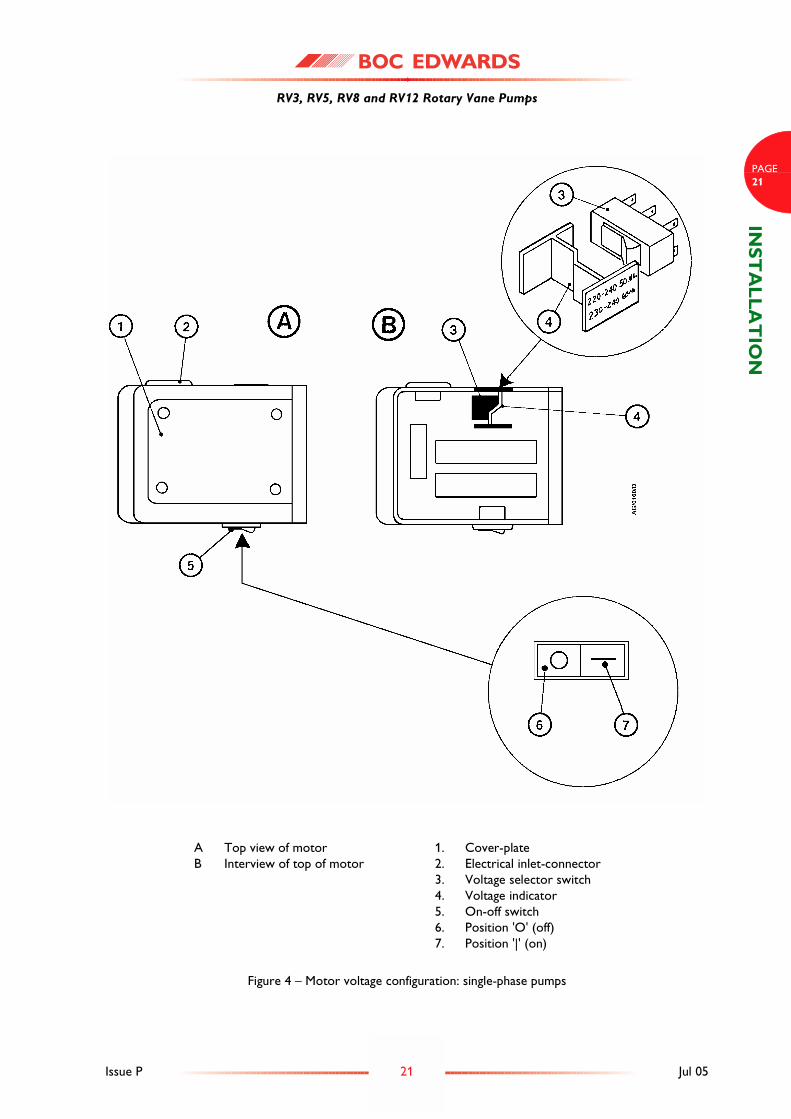
Refer to Figure 4 for the item numbers in brackets.
Ensure that the voltage shown on the voltage indicator (4) in the motor-cover corresponds with yourelectrical supply voltage. If it does not, you must change the configuration of the pump-motor to matchyour electrical supply voltage; use the procedure below.
1. Undo the four screws, remove the cover-plate (1) and lift out the voltage indicator moulding (4).
2. Press the voltage selector switch (3) to select the alternative position.
3. Turn the voltage indicator moulding over so that the outer panel shows the required voltage. Refitthe moulding.
4. Refit the cover-plate and secure it with the four screws.
3.7.2 Connect the pump to your electrical supply
Notes: In the UK, if you use a 13 A plug, it must comply with BS1363A and be fitted with a 13 A fuse whichcomplies with BS1362.
To prevent automatic restart of the pump-motor if the electrical supply is restored after an electrical supplyfailure, connect the pump to the electrical supply through suitable control equipment which must be resetmanually after an electrical supply failure.
Make the electrical connections to the pump-motor with an IEC 320 cable socket (cold condition type)that satisfies your local electrical standards.
To maintain compliance with CSA standards, you must only use CSA/UL certified electrical supply cablesand connectors. Cables must be SJT rated (minimum) and must incorporate an earth conductor. Theconductors in the cable must be a minimum of 18 AWG. The temperature rating of the cable must be
70 oC or greater.
CAUTION
Ensure that the motor is correctly configured for your electrical supply. If you operate the pump when the motor is not correctly configured for the electrical supply, you will damage the motor.
WARNING
Ensure that the electrical installation of the RV pump conforms with your local and national safety requirements. It must be connected to a suitably fused and protected
electrical supply and a suitable earth (ground) point.
Issue P 19 Jul 05

RV3, RV5, RV8 and RV12 Rotary Vane Pumps
INS
TA
LL
AT
ION
PAGE20
If your RV pump was supplied with an electrical supply cable, the cable will be fitted with a moulded IECconnector at one end. The other end of the cable may be fitted with a plug suitable for your localelectrical supply. A cable without a plug will contain wires colour coded as follows:
1. Ensure that the on/off switch on the motor (Figure 4, item 5) is in the 'off' position.
2. Insert the moulded IEC connector at the end of the cable into the electrical inlet-connector on themotor (Figure 4, item 2).
3. Connect the plug (if fitted) at the other end of the cable to your electrical supply. If a plug is notfitted, connect the wires in the cable to the correct terminals of your electrical supply.
3.7.3 Check the direction of rotation
Refer to Figure 1 for the item numbers in brackets.
1. Watch the motor cooling-fan through the motor fan-cover (13).
2. Use the on/off switch (12) to switch-on the electrical supply to the motor for a few seconds.
3. Check that the motor cooling-fan rotates in the correct direction (14) shown by the arrow on themotor fan-cover. If the direction of rotation is incorrect, switch off the electrical supply immediatelyand contact your supplier or BOC Edwards for advice.
Colour Use
Green and yellow Earth (ground)
Blue Neutral
Brown Live
CAUTION
Ensure that the pump-motor rotates in the correct direction. If it does not, the pump and your vacuum system can become pressurised.
Issue P 20 Jul 05
RV3, RV5, RV8 and RV12 Rotary Vane Pumps
INS
TA
LL
AT
ION
PAGE21
Figure 4 – Motor voltage configuration: single-phase pumps
A Top view of motorB Interview of top of motor
1. Cover-plate2. Electrical inlet-connector3. Voltage selector switch4. Voltage indicator5. On-off switch6. Position 'O' (off)7. Position '|' (on)
Issue P 21 Jul 05

RV3, RV5, RV8 and RV12 Rotary Vane Pumps
INS
TA
LL
AT
ION
PAGE22
3.8 Electrical installation: three-phase pumps
3.8.1 Check and configure the motor
1. Remove the screws which secure the cover of the motor terminal-box. Remove the cover.
2. Remove the cable-gland from the inside of the terminal-box and fit the cable-gland to the cableleadthrough hole in the side of the terminal-box.
3. Ensure that the motor is correctly configured for your electrical supply. If necessary, reconfigurethe links (Figures 5 and 6, item 1) to suit your electrical supply:
• For 200-230 V electrical supplies, the links must be configured as shown in Figure 5.
• For 380-460 V electrical supplies, the links must be configured as shown in Figure 6.
3.8.2 Connect the pump to your electrical supply
Notes: To prevent automatic restart of the pump-motor if the electrical supply is restored after an electrical supplyfailure, connect the pump to the electrical supply through suitable control equipment which must be resetmanually after an electrical supply failure.
To maintain compliance with CSA (Canadian Standards Association) standards, you must incorporate aswitch or circuit breaker in the pump electrical supply. The switch or circuit breaker must be close to thepump and easily accessible, and must be clearly marked to identify that it is the electrical supplydisconnection device for the pump.
We recommend that you connect the electrical supply to the motor through a starter or circuit breakerwhich has thermal over-current protection which can be adjusted to suit the full load current ratingsshown in Table 11. The fuse ratings in Table 11 are provided for guidance only. The supplier of yourthermal over-current protection device may specify different values to ensure correct operation of thefuse and the over-current protection device. Ensure that the fuse you use is suitable for the startingcurrents given in Table 11.
1. Pass the electrical supply cable through the cable-gland. The diameter of the electrical supply cableshould be in the range 7 to 11 mm.
2. Use insulated crimped connectors to connect the wires in the cable to the terminals U1, V1 andW1 and Earth (ground) in the terminal-box as shown in Figures 5 and 6. You must tighten the earth(ground) terminal connection to a torque of 2.13 to 2.87 Nm.
3. Ensure that the cover gasket is correctly positioned, then refit the cover to the terminal-box andsecure with the screws. Tighten the strain-relief nut on the cable-gland.
CAUTION
Ensure that the motor is correctly configured for your electrical supply. If you operate the pump when the motor is not correctly configured for the electrical supply, you will damage the motor.
WARNING
Ensure that the electrical installation of the RV pump conforms with your local and national safety requirements. It must be connected to a suitably fused and protected
electrical supply and a suitable earth (ground) point.
Issue P 22 Jul 05

RV3, RV5, RV8 and RV12 Rotary Vane Pumps
INS
TA
LL
AT
ION
PAGE23
Figure 5 – Three-phase electrical connections: 200-230 V
Figure 6 – Three-phase electrical connections: 380-460 V
A Starter/contactorB Motor terminal-box
1. Links
A Starter/contactorB Motor terminal-box
1. Links
Issue P 23 Jul 05

RV3, RV5, RV8 and RV12 Rotary Vane Pumps
INS
TA
LL
AT
ION
PAGE24
3.8.3 Check the direction of rotation
1. Refer to Figure 1. Watch the motor cooling-fan through the motor fan-cover (13).
2. Switch-on the electrical supply to the motor for a few seconds.
3. Check that the motor cooling-fan rotates in the correct direction shown by the arrow on themotor mounting plate. If the direction of rotation is incorrect:
• Switch off the electrical supply immediately.
• Isolate the pump from the electrical supply.
• Remove the terminal-box cover and swap wires L1 and L3: see Figures 5 and 6.
• Refit the cover to the terminal-box.
3.9 Inlet and outlet connections
Before you connect the pump to your vacuum system, fit the centring-ring and inlet-filter (supplied withthe pump) to the pump inlet-port (see Figure 5).
Take note of the following information when you connect the pump to your vacuum system. Refer toSection 7.4 for details of the accessories mentioned below. Use standard NW25 fittings (not supplied)when you connect the pump.
• For optimum pumping speeds, ensure that the pipeline connected to the pump-inlet is as short aspossible and has an internal diameter of 25 mm or larger.
• Support the vacuum pipelines to prevent loading of the coupling-joints.
• If necessary, incorporate flexible bellows in your system pipelines to reduce the transmission ofvibration and to prevent loading of coupling-joints. If you use flexible bellows, you must ensure thatyou use bellows which have a maximum pressure rating which is greater than the highest pressurethat can be generated in your system. We recommend that you use BOC Edwards flexible bellows.
• Use a suitable inlet trap if you pump condensable vapours or if you use the pump for very dustyapplications.
• Use a suitable valve to isolate the pump from your vacuum system if you need to pump condensablevapours or maintain vacuum when the pump is switched off.
• Ensure that sealing surfaces are clean and scratch-free.
CAUTION
Ensure that the pump-motor rotates in the correct direction. If it does not, the pump and your vacuum system can become pressurised.
WARNING
Connect the exhaust to a suitable treatment plant to prevent the discharge of dangerous gases and vapours to the surrounding atmosphere. Use a catchpot to prevent the
drainage of contaminated condensate back into the pump.
Issue P 24 Jul 05
RV3, RV5, RV8 and RV12 Rotary Vane Pumps
INS
TA
LL
AT
ION
PAGE25
In any of the following circumstances, we recommend that you fit an oil mist filter to the pump outlet:
• If you use the pump with the gas ballast control open (in position 'I' or position 'II').
• If you operate the pump with an inlet pressure greater than 10 mbar (1 x 10³ Pa) for extendedperiods.
• If you frequently pump down from atmospheric pressure.
The oil mist filter will trap the oil exhausted from the pump; you can reuse the oil if it is not contaminated.
3.10 Leak-test the system
Leak-test the system and seal any leaks found after you have installed the RV pump, to prevent leakageof substances out of the system and leakage of air into the system.
Issue P 25 Jul 05

RV3, RV5, RV8 and RV12 Rotary Vane Pumps
PAGE26
Issue P 26 Jul 05
This page intentionally blank.

RV3, RV5, RV8 and RV12 Rotary Vane Pumps
OP
ER
AT
ION
PAGE27
4 OPERATION
4.1 ATEX directive implications
4.1.1 Introduction
This equipment is designed to meet the requirements of Group II Category 3 equipment in accordancewith Directive 94/9/EC of the European Parliament and the Council of 23rd March 1994 on theapproximation of the laws of the Member States concerning equipment and protective systems intendedfor use in potentially explosive atmospheres. (The ATEX Directive)
The ATEX Category 3 applies in respect of potential ignition sources internal to the equipment. AnATEX Category has not been assigned in respect of potential ignition sources on the outside of theequipment as the equipment has not been designed for use where there is an external potentiallyexplosive atmosphere.
There is no potential source of ignition within the pump during normal operation but there may bepotential sources of ignition under conditions of predicted and rare malfunction as defined in theDirective. Accordingly, although the pump is designed to pump flammable materials and mixtures,operating procedures should ensure that under all normal and reasonably predicted conditions, thesematerials and mixtures are not within explosive limits. Category 3 is considered appropriate for theavoidance of ignition in the case of a rare malfunction which allows flammable materials or mixtures topass through the pump while within their explosive limits.
4.1.2 Flammable/pyrophoric materials
When flammable or pyrophoric materials are present within the equipment you must:
• Not allow air to enter the equipment.
• Ensure the system is leak tight.
• Use an inert gas purge (for example, a nitrogen purge) to dilute any flammable gases or vapoursentering the pump inlet, and/or use an inert gas purge to reduce the concentration of flammablegases or vapours in the pump and in the exhaust pipeline to less than one quarter of the gases'published lower explosive limits (LEL).
• Use an inert gas purge into the pump gas ballast connection to prevent the condensation offlammable vapours within the pump mechanism and exhaust pipeline.
WARNING
Do not expose any part of your body to vacuum. If you do, you may be injured.
WARNING
You must obey the instructions and take note of the precautions given below, to ensure that pumped gases do not enter their flammable ranges.
Issue P 27 Jul 05

RV3, RV5, RV8 and RV12 Rotary Vane Pumps
OP
ER
AT
ION
PAGE28
4.1.3 Gas purges
Switch on the inert gas purge to remove air from the pump and the exhaust pipeline before the processstarts. Switch off the purge flow at the end of the process only after any remaining flammable gases orvapours have been purged from the pump and exhaust pipeline.
If liquids that produce flammable vapours could be present in the pump foreline, then the inert gas purgeto the RV3, RV5, RV8 and RV12 rotary vane pump should be left on all the time this liquid is present.Flammable liquids could be present in the foreline as a result of condensation, or may be carried overfrom the process.
When you calculate the flow rate of inert gas required for dilution, consider the maximum flow rate forthe flammable gases/vapours that could occur. For example, if a mass flow controller is used to supplyflammable gases to the process, you should assume a flow rate for flammable gases that could arise if themass flow controller is fully open.
Continually measure the inert gas purge flow rate: if the flow rate falls below that required, you muststop the flow of flammable gases or vapours into the pump.
Note: We recommend that you obtain and read the Vacuum Pump and Vacuum System Safety manual(publication number P300-20-000), available from BOC Edwards or your supplier.
4.2 How to use the pump controls
4.2.1 Introduction
You can use the mode selector (Figure 1, item 11) and the gas-ballast control (Figure 1, item 5) tooptimise the performance of the RV pump for your application. The performance characteristics of thepump with the different control settings are shown in Tables 3 and 4. You can change the position ofboth the mode selector and the gas-ballast control when the pump is off or when the pump is operating.
WARNING
If you use inert gas purges to dilute dangerous gases to a safe level, ensure that the RV3, RV5, RV8 and RV12 rotary vane pump is shut down if an inert
gas supply fails.
WARNING
You must obey the instructions and take note of the precautions given below, to ensure that pumped gases do not enter their flammable ranges.
Issue P 28 Jul 05

RV3, RV5, RV8 and RV12 Rotary Vane Pumps
OP
ER
AT
ION
PAGE29
4.2.2 Mode selector
Note: Note:The pump is supplied with High Vacuum mode ! selected. If High Vacuum mode is selected and youcannot turn the mode selector by hand to select the High Throughput mode, use a suitable tool fitted tothe flat part of the mode selector to turn the selector.
The mode selector controls the flow of pressurised oil to the high vacuum stage of the pump (seeSection 1.4.1). You can turn the mode selector to one of two positions, as follows:
To select the High Vacuum mode !, turn the mode selector fully clockwise and tighten by hand. WhenHigh Vacuum mode is selected, there is a gap of approximately 3 mm between the mode selector andthe inner face of the side panel of the pump. Use this mode:
• to achieve ultimate vacuum
• to pump clean gases
• to pump clean condensable vapours.
To select the High Throughput mode !, turn the mode selector fully anticlockwise until it touches theinner face of the side panel of the pump, then gently tighten by hand. Use this mode:
• for long-term operation with high gas throughput (that is, inlet pressure > 50 mbar)
• to pump dirty condensable vapours
• to decontaminate the oil.
4.2.3 Gas-ballast control
Use the gas-ballast control to change the amount of air (or inert gas) introduced into the low vacuumstage of the pump (refer to Section 1.4.2). Use of gas-ballast will prevent the condensation of vapours inthe pump; the condensates would contaminate the oil. You can turn the gas-ballast control to select oneof three positions, as follows:
To select gas-ballast closed, turn the control to position '0'. Use this setting:
• to achieve ultimate vacuum
• to pump dry gases.
To select low flow gas-ballast, turn the control to position 'I'. Use this setting:
• to pump low concentrations of condensable vapours
• to decontaminate the oil.
To select high flow gas-ballast, turn the control to position 'II'. Use this setting:
• to pump high concentrations of condensable vapours.
When you use either low flow or high flow gas-ballast, there will be an increased rate of oil loss from thepump. Where possible, we recommend that you select low flow gas-ballast (position 'I') rather than highflow gas-ballast (position 'II') to minimise the loss of oil.
Issue P 29 Jul 05

RV3, RV5, RV8 and RV12 Rotary Vane Pumps
OP
ER
AT
ION
PAGE30
4.3 Start-up procedure
If the oil is contaminated, or if the pump temperature is below 12 °C, or if the electrical supply voltageis more than 10% below the lowest voltage specified on the voltage indicator (Figure 4, item 4), the pumpmay operate at a reduced speed for a few minutes. On single-phase pumps, if the pump continues tooperate at reduced speed, the motor thermal overload device will open and stop the pump. When themotor has cooled, the thermal overload device will reset automatically and the pump will restart.
1. Check that the pump oil-level is between the MAX and MIN marks on the bezel of the oil-levelsight-glass; if it is not, refer to Section 5.3.
2. Turn the mode selector fully clockwise to select High Vacuum mode ! or fully anticlockwise toselect High Throughput mode !, as required (refer to Section 4.2.2).
3. Turn the gas-ballast control to position '0', 'I' or 'II', as required (refer to Section 4.2.3).
4. Switch on the electrical supply to the pump; on single-phase pumps, use the on/off switch.
5. If you want to achieve ultimate vacuum, to pump condensable vapours or to decontaminate thepump oil, refer to the procedures in Sections 4.4, 4.5 and 4.6 respectively. Otherwise, open thevacuum system isolation-valve.
4.4 To achieve ultimate vacuum
If the pump does not achieve the performance specified in Section 2.2, make sure that this is not due toyour system design before you contact your supplier or BOC Edwards for advice. In particular, thevapour pressure of all materials used in your vacuum system (including pump oil, see below) must bemuch lower than the specified ultimate vacuum of the pump. Refer to Section 5.12.3 for a list of possiblecauses for failure to achieve the specified performance; note however that the most common causes are:
• Your pressure measurement technique or gauge head is unsuitable or the gauge head is faulty.
• You have used an oil other than the recommended oil, and the vapour pressure of the oil is higherthan the specified ultimate vacuum of the pump.
Use the following procedure to achieve ultimate vacuum:
1. Isolate the RV pump from your vacuum system.
2. Turn the mode selector to select High Throughput mode !, set the gas-ballast control to low flow(position 'I') and operate the pump for at least 1 hour (or overnight) to thoroughly purge the oil ofcontaminants.
3. Turn the mode selector to select High Vacuum mode ! and close the gas-ballast control (that is,set it to position '0').
Open the vacuum system isolation-valve and pump down to ultimate vacuum.
WARNING
Ensure that your system design does not allow the exhaust pipeline to be blocked.
Issue P 30 Jul 05

RV3, RV5, RV8 and RV12 Rotary Vane Pumps
OP
ER
AT
ION
PAGE31
4.5 To pump condensable vapours
Use gas-ballast (gas-ballast control in position 'I' or 'II') when there is a high proportion of condensablevapours in the process gases.
1. Close the vacuum system isolation-valve.
2. Turn the mode selector fully clockwise to select High Vacuum mode ! or fully anticlockwise toselect High Throughput mode !, as required (refer to Section 4.2.2).
3. Turn the gas-ballast control to high flow (position 'II') and operate the pump for 30 minutes towarm the oil; this will help to prevent vapour condensation in the pump.
4. Set the gas-ballast control to the position required for your application (refer to Section 4.2.3 andthe data in Tables 3 and 4).
5. Open the vacuum system isolation-valve.
After you have pumped condensable vapours, you can (if necessary) decontaminate the oil: use theprocedure in Section 4.6.
4.6 To decontaminate the oil
The oil in the pump should be clear; if the oil is cloudy or discoloured, it is contaminated with processvapours.
1. Look at the condition of the oil in the oil-level sight-glass (Figure 1, item 8). If the oil is cloudy ordiscoloured, continue with the procedure at Step 2 below.
2. Close the vacuum system isolation-valve.
3. Turn the mode selector fully anticlockwise to select High Throughput mode !. Set the gas-ballastcontrol to low flow (position 'I').
4. Operate the pump until the oil is clear.
4.7 Unattended operation
The RV pump is designed for unattended operation under the normal operating conditions specified inSection 2.1. However, we recommend that you check the pump at regular intervals of not more than 14days, or more frequently if you pump high volumes of gas or vapour.
On single-phase pumps, the motor is protected by an overload device which isolates the pump from theelectrical supply when critical temperature or current levels are exceeded. The overload device resetsautomatically when the motor has cooled. When you check the pump, make sure that the pump is notgoing through a repetitive cycle of thermal overload failures and automatic resets. If necessary, changethe mode selector to High Throughput mode ! and reduce the thermal load from the pumped gases, toprevent overheating of the pump.
Issue P 31 Jul 05

RV3, RV5, RV8 and RV12 Rotary Vane Pumps
OP
ER
AT
ION
PAGE32
4.8 Shut-down
We recommend, as described in the procedure below, that you decontaminate the oil before you shutdown the pump; this will prevent damage to the pump by the contaminates in the oil.
1. Refer to Section 4.6 and decontaminate the oil, as required.
2. Close the vacuum system isolation-valve (if not already closed).
3. Close gas-ballast (that is, set the gas-ballast control to position '0').
4. On single-phase pumps, use the on/off switch to switch off the pump.
5. Switch off the electrical supply to the pump.
Issue P 32 Jul 05

RV3, RV5, RV8 and RV12 Rotary Vane Pumps
MA
INT
EN
AN
CE
PAGE33
5 MAINTENANCE
5.1 Safety information
• If your pump is PFPE-prepared, refer to Section 8 before you maintain the pump.
• A suitably trained and supervised technician must maintain the pump. Obey your local and nationalsafety requirements.
• Ensure that the maintenance technician is familiar with the safety procedures which relate to thepump-oil and the products processed by the pumping system.
• Check that all the required parts are available and of the correct type before you start work.
• Isolate the pump and other components from the electrical supply so that they cannot be operatedaccidentally.
• Allow the pump to cool (so that it is at a safe temperature for skin contact) before you startmaintenance work. Make sure the pump is switched off in case the thermal overload device restartsthe pump.
• Do not reuse 'O' rings and seals if they are damaged.
• After maintenance is completed, recheck the direction of pump rotation if the electrical supply hasbeen disconnected.
• The pump and the pump-oil will be contaminated with the process chemicals that have beenpumped during operation. Ensure that the pump is decontaminated before maintenance and thatyou take adequate precautions to protect people from the effects of dangerous substances ifcontamination has occurred.
• Do not touch or inhale the thermal breakdown products of fluorinated materials which may bepresent if the pump has been heated to 310 oC and above. Fluorinated materials are safe in normaluse but can decompose into very dangerous substances (which may include hydrofluoric acid) ifthey are heated to 310 oC and above. The pump may have overheated if it was misused, if itmalfunctioned, or if it was in a fire. Material Safety Data Sheets for fluorinated materials used in thepump are available on request: contact your supplier or BOC Edwards.
• If necessary, maintain the motor as specified in the manufacturers information supplied with themotor.
WARNING
Obey the safety instructions given below and take note of appropriate precautions. If you do not, you can cause injury to people and damage to equipment.
Issue P 33 Jul 05

RV3, RV5, RV8 and RV12 Rotary Vane Pumps
MA
INT
EN
AN
CE
PAGE34
5.2 Maintenance plan
The plan shown in Table 12 details the routine maintenance operations necessary to maintain RV pumpsin normal use. Instructions for each operation are given in the section shown.
More frequent maintenance may be required if the pump is used to pump corrosive or abrasive gasesand vapours, such as solvents, organic substances and acids; in these circumstances, we recommend thatyou replace the pump seals every year (refer to Section 7.3 for details of available spares). If necessary,adjust the maintenance plan according to your experience.
When you maintain the RV pump, use BOC Edwards spares and maintenance kits; these contain all ofthe components necessary to complete maintenance operations successfully. The Item Numbers of thespares and kits are given in Section 7.3.
5.3 Check the oil-level
Note: If required, you can check the oil-level while the pump is operating, however you must switch off the pumpand isolate the pump and other components in the pumping system from the electrical supply before youpour oil into the pump.
Refer to Figure 1 for the items in brackets.
1. Check that the oil-level in the sight-glass (8) is between the MAX and MIN level marks on the bezelof the sight-glass.
2. If the oil-level is near to or below the MIN level mark, remove one of the filler-plugs (6) and pourmore oil into the reservoir until the oil reaches the MAX level mark. If the oil-level goes abovethe MAX mark, remove the drain-plug (9) and drain the excess oil from the pump. Refit the filler-plug.
3. If the oil is contaminated, drain and refill the pump with clean oil as described in Section 5.4.
Operation Frequency Refer to Section
Check the oil-level Monthly 5.3
Replace the oil Every 3000 hours of operation 5.4
Inspect and clean the inlet-filter Yearly 5.5
Inspect and clean the gas-ballast control Yearly 5.6
Clean the oil-level sight-glass Yearly 5.7
Clean the motor fan-cover and enclosure Yearly 5.8
Clean and overhaul the pump Every 15000 hours of operation 5.9
Fit new blades Every 30000 hours of operation 5.10
Test the motor condition Every 15000 hours of operation 5.11
Table 12 – Maintenance plan
Issue P 34 Jul 05

RV3, RV5, RV8 and RV12 Rotary Vane Pumps
MA
INT
EN
AN
CE
PAGE35
5.4 Replace the oil
1. Refer to Figure 1. Operate the pump for approximately ten minutes to warm the oil, then switchoff the pump (this lowers the viscosity of the oil and enables it to be drained from the pump moreeasily).
2. Isolate the pump from your electrical supply and disconnect it from your vacuum system.
3. Remove one of the oil filler-plugs (6).
4. Place a suitable block under the pump-motor to tilt the pump and place a suitable container underthe drain-plug (9). Remove the drain-plug and allow the oil to drain into the container.
5. If the oil drained from the pump is contaminated, pour clean oil into the filler-hole and allow it todrain out of the pump. Repeat this step until the oil reservoir in the pump has been thoroughlycleaned.
6. Refit the drain-plug, remove the block and reconnect the pump to your vacuum system.
7. Fill a suitable container with clean oil and pour the oil into the filler hole until the oil-level reachesthe MAX level mark on the bezel of the sight-glass (8).
8. Allow a few minutes for the oil to drain into the pump. If necessary, add more oil. Refit the filler-plug.
5.5 Inspect and clean the inlet-filter
1. Refer to Figure 7. Disconnect your vacuum system from the pump inlet-port (3) and remove thecentring-ring and filter assembly (1) and the 'O' ring (2). Inspect the centring-ring and the 'O' ring.If they are clean, continue at Step 5. If they are not clean, continue at Step 2.
2. Remove the 'O' ring (2) from the centring-ring and filter assembly (1). Do not allow the 'O' ring tocome into contact with the cleaning solution.
3. Wash the centring-ring and filter assembly in a suitable cleaning solution and allow it to dry.
4. If necessary, wipe the 'O' ring with a clean, dry, lint-free cloth.
5. Refit the centring-ring and filter assembly and the 'O' ring to the inlet-port. Refit your vacuumsystem to the pump inlet-port.
Figure 7 – Inlet-filter assembly
1. Centring-ring and filter assembly2. 'O' ring3. Inlet-port
Issue P 35 Jul 05

RV3, RV5, RV8 and RV12 Rotary Vane Pumps
MA
INT
EN
AN
CE
PAGE36
5.6 Inspect and clean the gas-ballast control
Note: The gas-ballast filter element (Figure 8, item 7) is retained in its seating with adhesive; do not try to removeit.
1. Refer to Figure 8. Turn the gas-ballast control (1) to the high flow position (position 'II').
2. Push the control down against the compression spring (6) as far as it will go, then turn the controlanticlockwise slightly to release the bayonet-lugs (5) and remove the control.
3. If necessary, wipe the control with a clean, dry, lint-free cloth and check that the air-hole (3) is notblocked.
4. Refit the control into the gas-ballast inlet and ensure that the compression spring locates correctlybetween the bayonet-lugs.
5. Push the control down as far as it will go and then turn the control clockwise slightly until thebayonet-lugs engage correctly.
6. Reset the gas-ballast control to the required position.
Figure 8 – Gas-ballast control assembly
1. Gas-ballast control2. 'O' ring3. Air-hole4. 'O' ring5. Bayonet-lugs6. Compression spring7. Filter element
Issue P 36 Jul 05

RV3, RV5, RV8 and RV12 Rotary Vane Pumps
MA
INT
EN
AN
CE
PAGE37
5.7 Clean the oil-level sight-glass
Refer to Figure 9 for the item numbers in brackets.
1. Drain the oil as described in Section 5.4.
2. Undo the two screws (1) and remove the bezel (2), the sight-glass (3) and the 'O' ring (4) from theoil-box (5).
3. Clean the screws, bezel and sight-glass with a suitable cleaning solution.
4. Wipe the 'O' ring with a clean, dry, lint-free cloth.
5. Wipe the sight-glass recess in the oil-box with the cloth.
6. Refit the 'O' ring, sight-glass and bezel and secure with the two screws.
7. Refill the pump with oil as described in Section 5.4.
8. Check that the sight-glass does not leak.
Figure 9 – Sight-glass assembly
1. Screws (2 off M6 x 20)2. Bezel3. Sight-glass4. 'O' ring5. Oil-box
Issue P 37 Jul 05

RV3, RV5, RV8 and RV12 Rotary Vane Pumps
MA
INT
EN
AN
CE
PAGE38
5.8 Clean the motor fan-cover and enclosure
If the motor fan-cover and enclosure are not kept clean, the air-flow over the motor can be restrictedand the pump may overheat.
1. Switch off the pump and disconnect it from the electrical supply.
2. Use a dry cloth and a soft brush to remove dirt and deposits from the fan-cover and enclosure.
5.9 Clean and overhaul the pump
Clean and overhaul the pump as described in the instructions supplied with the clean and overhaul kit(see Section 7.3).
5.10 Fit new blades
Fit new blades to the pump as described in the instructions supplied with the blade kit (see Section 7.3).
5.11 Test the motor condition
Test the earth (ground) continuity and the insulation resistance of the pump-motor, in accordance withlocal regulations for periodic testing of electrical equipment.
The motor of single-phase RV pumps complies with IEC 1010-1. We recommend that, to maintaincompliance with IEC 1010-1, the earth continuity is less than 0.1 Ω and the insulation resistance is greaterthan 10 MΩ.
If the motor fails these tests, you must replace the motor.
5.12 Fault-finding
5.12.1 Introduction
A list of fault conditions and their possible causes is provided in the following sections to assist you infault-finding. If you are unable to rectify a fault when you use this guide, call your nearest BOC EdwardsService Centre for help.
5.12.2 The pump has failed to start
• The electrical supply fuse has failed
• The electrical supply voltage does not match that of the motor
• The outlet pipeline or the outlet-filter (if fitted) is blocked
• The oil temperature is below 12 oC
• The oil is too viscous
• The oil is contaminated
• The pump has seized after long storage
• The pump has been left to stand after contaminants have been pumped and has seized
• The motor is faulty.
Issue P 38 Jul 05

RV3, RV5, RV8 and RV12 Rotary Vane Pumps
MA
INT
EN
AN
CE
PAGE39
5.12.3 The pump has failed to achieve the specified performance (has failed to reach ultimate vacuum)
• Your pressure measurement technique or gauge head is unsuitable or gives an incorrect indicationof pressure. For example, a contaminated Pirani gauge can indicate a pressure which is several timeshigher than the actual pressure in the system.
• You have filled the pump with the wrong type of oil
• There is a leak in your vacuum system
• The mode selector and gas-ballast control are set incorrectly
• The oil-level is below minimum level
• The oil is contaminated
• Your vacuum fittings are dirty or damaged
• The inlet-filter is blocked
• The pump has not warmed up.
5.12.4 The pump is noisy
• The motor fan-cover is damaged
• The motor bearings are worn
• The oil is contaminated with solid particles.
5.12.5 The pump surface temperature is above 100 oC
Note: If the inlet pressure is continuously higher than 100 mbar (1 x 10⁴ Pa), the surface temperature of theRV12 pump can reach 115 oC when the ambient temperature is 40 oC.
• The ambient temperature is too high
• The cooling-air supply is insufficient or is too hot
• The electrical supply voltage is too high
• The outlet-filter or the outlet pipeline is blocked
• The oil-level is below minimum level
• You have filled the pump with the wrong type of oil
• The oil is contaminated
• The process gas is too hot or the throughput is too high.
5.12.6 The vacuum is not fully maintained after the pump is switched off
• The gas-ballast control is open (that is, in position 'I' or 'II')
• The inlet valve-pad is damaged
• The inlet valve has not closed.
Issue P 39 Jul 05

RV3, RV5, RV8 and RV12 Rotary Vane Pumps
MA
INT
EN
AN
CE
PAGE40
5.12.7 The pumping speed is poor
• The connecting pipelines are too small in diameter
• The connecting pipelines are too long
• The inlet-filter is blocked.
5.12.8 There is an external oil leak
• The outer shaft-seal is worn or damaged
• The oil-box gaskets have deteriorated
• There is an oil leak from the gas-ballast control
• There is an oil leak from the drain-plug
• There is an oil leak from the sight-glass
Issue P 40 Jul 05
RV3, RV5, RV8 and RV12 Rotary Vane Pumps
ST
OR
AG
E A
ND
DIS
PO
SA
L
PAGE41
6 STORAGE AND DISPOSAL
6.1 Storage
Note: If you will store a new pump in conditions of high humidity, remove the pump from its cardboard packagingbox; dispose of the box (refer to Section 6.2).
Use the following procedure to store the pump:
1. Shut-down the pump as described in Section 4.8.
2. Disconnect the pump from the electrical supply.
3. Purge your vacuum system and the pump with dry nitrogen and disconnect the pump from yourvacuum system.
4. Replace the oil as described in Section 5.4.
5. Place and secure protective covers over the inlet and outlet-ports.
6. Store the pump in cool, dry conditions until required for use. When required, prepare and installthe pump as described in Section 3. If the pump has been stored for more than a year, before youinstall the pump you must clean and overhaul it as described in the instructions supplied with theclean and overhaul kit.
6.2 Disposal
Dispose of the pump and any components removed from it safely in accordance with all local and nationalsafety and environmental requirements.
Take particular care with components and waste oil which have been contaminated with dangerousprocess substances.
Do not incinerate fluoroelastomer seals and 'O' rings.
CAUTION
Observe the storage temperature limits stated in Section 2.1. Storage below -30 oC will permanently damage the pump seals.
Issue P 41 Jul 05

RV3, RV5, RV8 and RV12 Rotary Vane Pumps
PAGE42
Issue P 42 Jul 05
This page intentionally blank.
RV3, RV5, RV8 and RV12 Rotary Vane Pumps
SE
RV
ICE
AN
D S
PA
RE
S
PAGE43
7 SERVICE AND SPARES
7.1 Introduction
BOC Edwards products, spares and accessories are available from BOC Edwards companies in Belgium,Brazil, China, France, Germany, Israel, Italy, Japan, Korea, Singapore, United Kingdom, U.S.A and aworld-wide network of distributors. The majority of these centres employ Service Engineers who haveundergone comprehensive BOC Edwards training courses.
Order spare parts and accessories from your nearest BOC Edwards company or distributor. When youorder, state for each part required:
• Model and Item Number of your equipment
• Serial number
• Item Number and description of part.
7.2 Service
BOC Edwards products are supported by a world-wide network of BOC Edwards Service Centres. EachService Centre offers a wide range of options including: equipment decontamination; service exchange;repair; rebuild and testing to factory specifications. Equipment which has been serviced, repaired orrebuilt is returned with a full warranty.
Your local Service Centre can also provide BOC Edwards engineers to support on-site maintenance,service or repair of your equipment.
For more information about service options, contact your nearest Service Centre or otherBOC Edwards company.
7.3 Spares
See Table 13 for the spares and maintenance kits available for the RV pumps.
Issue P 43 Jul 05

RV3, RV5, RV8 and RV12 Rotary Vane Pumps
SE
RV
ICE
AN
D S
PA
RE
S
PAGE44
Spare
Item Numbers
Hydrocarbon- prepared
pumps
PFPE- prepared
pumps
Ultragrade 19 oil, 1 litreUltragrade 19 oil, 4 litres
H110-25-015H110-25-013
--
Fomblin 06/6 oil, 1 kgFomblin 06/6 oil, 5 kg
--
H113-06-019H113-06-020
Clean and overhaul kit (Standard) A652-01-131 A652-01-131
RV3 Blade kit A652-01-130 A652-01-130
RV5 Blade kit A653-01-130 A653-01-130
RV8 Blade kit A654-01-130 A654-01-130
RV12 Blade kit A655-01-130 A655-01-130
RV3 Cartridge Kit A652-01-032 A652-09-032
RV5 Cartridge Kit A653-01-032 A653-09-032
RV8 Cartridge Kit A654-01-032 A654-09-032
RV12 Cartridge Kit A655-01-032 A655-09-032
Inlet-valve kit A652-01-036 A652-01-036
Motor Starting Relay Kit A505-74-000 A505-74-000
Outer Shaft-Seal Kit A652-01-134 A652-01-134
Rotor Sleeve Kit A652-01-136 A652-09-136
RV3/RV5 Motor Kit (Europe/USA) 50/60 Hz, 250/300 W, 1 phase, 110-120/220-240 V
A652-99-000 A652-99-000
RV8/RV12 Motor Kit (Europe/USA) 50/60 Hz, 450/550 W, 1 phase, 110-120/220-240 V
A654-99-000 A654-99-000
RV3/RV5 Motor Kit (Japan) 50/60 Hz, 250/300 W, 1 phase, 100/200 V
A652-98-000 A652-98-000
RV8/RV12 Motor Kit (Japan) 50/60 Hz, 450/550 W, 1 phase, 100/200 V
A654-98-000 A654-98-000
RV3/RV5 Motor Kit (Europe/USA/Japan 50/60 Hz, 250/300 W, 3 phase, 200-230/380-460 V
A652-97-000 A652-97-000
RV8/RV12 Motor Kit (Europe/USA/Japan) 50/60 Hz, 450/550 W, 3 phase, 200-230/380-460 V
A654-97-000 A654-97-000
Clean and Overhaul Kit (Nitrile) A652-01-137 -
Table 13 – Spares and maintenance kits
Issue P 44 Jul 05

RV3, RV5, RV8 and RV12 Rotary Vane Pumps
SE
RV
ICE
AN
D S
PA
RE
S
PAGE45
7.4 Accessories
7.4.1 Introduction
The accessories which can be fitted to the RV pump are shown in Figure 10, and their Item Numbers arelisted in Table 14.
These accessories are briefly described in Sections 7.4.2 to 7.4.14.
7.4.2 Inlet catchpot
The inlet catchpot traps any liquid droplets and prevents their entry into the pump.
7.4.3 Inlet dust filter
The inlet dust filter protects the pump against abrasive dust.
Accessory Refer toSection
Item Number
ITO20K Inlet catchpot 7.4.2 A441-10-000
ITF20K Inlet dust filter 7.4.3 A442-15-000
ITD20K Inlet desiccant trap 7.4.4 A445-10-000
ITC20K Inlet chemical trap 7.4.5 A444-10-000
FL20K Foreline trap 7.4.6 A133-05-000
EMF10 Outlet mist filter 7.4.7 A462-26-000
EMF20 Outlet mist filter 7.4.7 A462-29-000
Gas-ballast adaptor 7.4.8 A505-02-000
Gravity oil drain kit 7.4.9 A505-01-000
Oil drain-extension 7.4.10 A505-03-000
Exhaust nozzle kit 7.4.11 A505-09-000
Vibration isolators (pack of four) 7.4.12 A248-01-404
EBV20 Solenoid Operated Gas-Ballast Valve220-240 V 50/60 Hz100-120 V 50/60 Hz
7.4.13A500-06-930A500-06-984
PV25EK Pipeline Valve (aluminium)220-240 V 50/60 Hz110-127 V 50/60 Hz
7.4.14C413-01-000C413-03-000
PV25EK Pipeline Valve (stainless steel)220-240 V 50/60 Hz110-127 V 50/60 Hz
7.4.14C413-02-000C413-04-000
Table 14 – Accessory Item Numbers
Issue P 45 Jul 05

RV3, RV5, RV8 and RV12 Rotary Vane Pumps
SE
RV
ICE
AN
D S
PA
RE
S
PAGE46
7.4.4 Inlet desiccant trap
Use a desiccant trap when you pump limited quantities of water vapour at high pumping speeds to a lowvapour pressure.
7.4.5 Inlet chemical trap
The inlet chemical trap protects the pump against chemically active gases.
7.4.6 Foreline trap
Use a foreline trap on a clean pumping system to prevent back-migration of pump-oil vapour into yourvacuum system.
7.4.7 Outlet mist filter
The outlet mist filter separates and traps oil droplets in the pump outlet to prevent oil mist discharge.
7.4.8 Gas-ballast adaptor
Fit the gas-ballast adaptor in place of the gas-ballast control on the pump. The adaptor allows you to fita solenoid operated gas-ballast valve or a controlled supply of inert gas to the pump.
7.4.9 Gravity oil drain kit
Fit the oil drain kit between the drain port of the outlet mist filter and the oil filler-plug on the pump.When the kit is fitted, oil will be returned from the mist filter to the pump when the pump is switchedoff or when the gas-ballast control is closed (in the '0' position) and there is no process gas being pumped.
7.4.10 Oil drain-extension
Fit the oil drain-extension between the oil drain port on the pump and the oil drain-plug to make thedrainage of oil from the pump easier.
7.4.11 Exhaust nozzle kit
The exhaust nozzle replaces the outlet flange. Use the exhaust nozzle to connect the pump outlet to 12mm internal diameter plastic hose.
7.4.12 Vibration isolators
Vibration isolators reduce vibration and noise when the pump is floor or frame mounted and help toreduce strain when the mounting area is uneven.
7.4.13 Solenoid operated gas-ballast valve
Fit the gas-ballast valve in place of the built-in gas-ballast control on the pump; you must fit the gas-ballastadaptor (see Section 7.4.8) with the solenoid operated gas-ballast valve. The valve provides automaticon/off control of the gas-ballast and isolates the gas-ballast inlet when the pump is switched off.
7.4.14 Solenoid operated pipeline valve
Fit the pipeline valve between your vacuum system and the pump-inlet to provide additional systemprotection when the pump is switched off.
Issue P 46 Jul 05

RV3, RV5, RV8 and RV12 Rotary Vane Pumps
SE
RV
ICE
AN
D S
PA
RE
S
PAGE47
Figure 10 – Accessories
1. Inlet catchpot2. Inlet dust filter3. Inlet desiccant trap4. Inlet chemical trap5. Solenoid operated gas-ballast valve6. Foreline trap
7. Solenoid operated pipeline valve 8. Outlet mist filter9. Gas-ballast adaptor10. Gravity oil drain kit11. Vibration isolators12. Oil drain-extension
Issue P 47 Jul 05

RV3, RV5, RV8 and RV12 Rotary Vane Pumps
PAGE48
Issue P 48 Jul 05
This page intentionally blank.

RV3, RV5, RV8 and RV12 Rotary Vane Pumps
PF
PE
-PR
EP
AR
ED
RV
PU
MP
S
PAGE49
8 PFPE-PREPARED RV PUMPS
8.1 Summary
If you have ordered a PFPE-prepared RV pump, the pump will be supplied prepared for use with BOCEdwards PFPE mechanical pump oils, such as Fomblin YVAC 06/6 and Krytox 1506.
PFPE-prepared RV pumps are suitable for pumping high concentrations of oxygen.
We recommend that you refer to BOC Edwards publication P300-20-000 (Vacuum pump and VacuumSystem Safety) before you install and use a PFPE-prepared RV pump.
8.2 Installation
When you fill the RV pump with oil (as described in Section 3.5), you must use a suitable BOC EdwardsPFPE oil. You must not use a hydrocarbon oil.
8.3 Operation
Operation of a PFPE-prepared RV pump is as specified in Section 4, but take note of the warning above.
8.4 Maintenance
• Take additional care if you suspect that the pump (and hence the PFPE oil) has overheated.
• Do not touch or inhale the thermal breakdown products of PFPE oil which may be present if thepump has been heated to 260 oC and above. PFPE oils are safe in normal use but can decomposeinto very dangerous substances if they are heated to 260 oC and above. The pump may haveoverheated if it was misused, if it malfunctioned, or if it was in a fire. Material Safety Data Sheetsfor PFPE oils used in the pump are available on request: contact your supplier or BOC Edwards.
Fomblin oil has different properties from other pump oils, therefore:
• If you fill your PFPE-prepared RV pump with Fomblin oil, we recommend that you regularly checkfor oil leaks, particularly around the shaft seals.
• If you detect an oil leak, contact your supplier or BOC Edwards for advice.
CAUTION
Never use hydrocarbon lubricants in a PFPE-prepared pump.
WARNING
PFPE-prepared RV pumps are suitable for pumping high concentrations of oxygen, but we recommend that you do not use a PFPE-prepared RV pump for the pumping of hazardous
materials.
WARNING
Obey the safety instructions given below and take note of appropriate precautions. If you do not, you can cause injury to people.
Issue P 49 Jul 05

RV3, RV5, RV8 and RV12 Rotary Vane Pumps
PAGE50
Issue P 50 Jul 05
This page intentionally blank.
RV3, RV5, RV8 and RV12 Rotary Vane Pumps
PF
PE
-PR
EP
AR
ED
RV
PU
MP
S
PAGE51
9 BARESHAFT RV PUMPS
9.1 Description
Two types of bareshaft pump are available:
• To suit an IEC72-1 motor with an (IMB14) FT85 face mounting and 14 mm diameter shaft.
• To suit a NEMA 56C motor with a 5/8 inch diameter shaft.
The motor you will fit must have a power rating which is adequate for use with the RV pump: refer tothe pump electrical data section in the manual.
Note: The performance data given in Section 2 applies to pumps supplied with a motor fitted as standard. Ona bareshaft pump, the performance may be affected by the type of motor fitted.
9.2 Fit the motor to the bareshaft pump
1. Refer to Figure 11. Use the four screws (455) to fit the motor support (453) to the motor.
2. Use the two screws (422) to fit the lifting plate (413), then fit the lifting plate cover (414).
3. Fit the fan ducting sheet (409).
4. Ensure that key ‘B’ is in place on the motor shaft, then push the fan (410) onto the shaft. Ensure that:
• The end of the shaft aligns with the bottom of the cavity in the fan.
• The back of the fan is 2.5 mm from the ducting sheet.
5. Secure the fan to the shaft with the screw (454): tighten the screw to a torque between 7 and 9 Nm.
6. Use a suitable lubricant on the coupling element (411) then fit the element to the coupling hub.
7. Align the coupling element in the hub with the coupling in the fan and fit the motor to the pump.
8. Secure the motor with the four screws (421). Tighten the screws to a torque of between 10 and12 Nm. Note that:
• The gap between the coupling faces must be 2 mm or less.
• If necessary, adjust the position of the coupling hub on the pump shaft so that the gap iscorrect.
Issue P 51 Jul 05
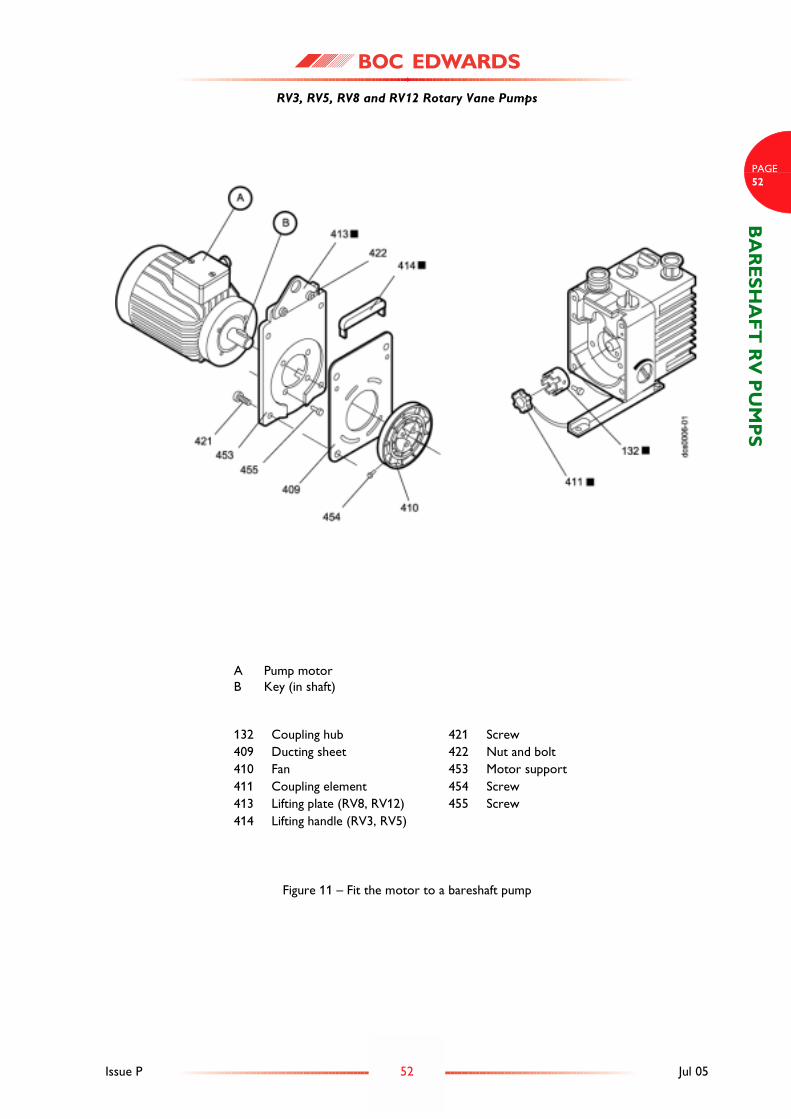
RV3, RV5, RV8 and RV12 Rotary Vane Pumps
BA
RE
SH
AF
T R
V P
UM
PS
PAGE52
Figure 11 – Fit the motor to a bareshaft pump
A Pump motorB Key (in shaft)
132 Coupling hub409 Ducting sheet410 Fan411 Coupling element413 Lifting plate (RV8, RV12)414 Lifting handle (RV3, RV5)
421 Screw422 Nut and bolt453 Motor support454 Screw455 Screw
Issue P 52 Jul 05

Return of BOC Edwards Equipment - Procedure
Form HS1
INTRODUCTIONBefore returning your equipment, you must warn BOC Edwards if substances you used (and produced)in the equipment can be hazardous. This information is fundamental to the safety of our Service Centreemployees and will determine the procedures employed to service your equipment.Complete the Declaration (HS2) and send it to BOC Edwards before you dispatch theequipment. It is important to note that this declaration is for BOC Edwards internal use only, andhas no relationship to local, national or international transportation safety or environmentalrequirements. As the person offering the equipment for shipment, it is your responsibility to ensurecompliance with applicable laws.
GUIDELINES• Equipment is 'uncontaminated' if it has not been used, or if it has only been used with substances
that are not hazardous. Your equipment is 'contaminated' if it has been used with any substancesclassified as hazardous under EU Directive 67/548/EEC (as amended) or OSHA Occupational Safety(29 CFR 1910).
• If your equipment has been used with radioactive substances, biological or infectious agents,mercury, polychlorinated biphenyls (PCB’s), dioxins or sodium azide, you must decontaminate itbefore you return it to BOC Edwards. You must send independent proof of decontamination (forexample a certificate of analysis) to BOC Edwards with the Declaration (HS2). Phone BOCEdwards for advice.
• If your equipment is contaminated, you must either:• Remove all traces of contamination (to the satisfaction of laws governing the transportation of
dangerous/hazardous substances).• Or, properly classify the hazard, mark, manifest and ship the equipment in accordance with
applicable laws governing the shipment of hazardous materials.Note: Some contaminated equipment may not be suitable for airfreight.
PROCEDURE1. Contact BOC Edwards and obtain a Return Authorisation Number for your equipment.2. Complete the Return of BOC Edwards Equipment - Declaration (HS2).3. If the equipment is contaminated, you must contact your transporter to ensure that you properly
classify the hazard, mark, manifest and ship the equipment, in accordance with applicable lawsgoverning the shipment of contaminated/hazardous materials. As the person offering the equipmentfor shipment, it is your responsibility to ensure compliance with applicable law. Note: Equipmentcontaminated with some hazardous materials, such as semiconductor by-products,may not be suitable for airfreight - contact your transporter for advice.
4. Remove all traces of hazardous gases: pass an inert gas through the equipment and any accessoriesthat will be returned to BOC Edwards. Where possible, drain all fluids and lubricants from theequipment and its accessories.
5. Seal up all of the equipment's inlets and outlets (including those where accessories were attached)with blanking flanges or, for uncontaminated product, with heavy gauge tape.
6. Seal equipment in a thick polythene/polyethylene bag or sheet.7. If the equipment is large, strap the equipment and its accessories to a wooden pallet. If the
equipment is too small to be strapped to a pallet, pack it in a suitable strong box.8. Fax or post a copy of the Declaration (HS2) to BOC Edwards. The Declaration must arrive before
the equipment.9. Give a copy of the Declaration (HS2) to the transporter. You must tell your transporter if the
equipment is contaminated.10. Seal the original Declaration in a suitable envelope: attach the envelope securely to the outside of
the equipment package, in a clear weatherproof bag.WRITE YOUR RETURN AUTHORISATION NUMBER CLEARLY ON THEOUTSIDE OF THE ENVELOPE OR ON THE OUTSIDE OF THE EQUIPMENTPACKAGE.P
900-
70-0
00 Is
sue
K

Return of BOC Edwards Equipment - Declaration
Form HS2
You must:
• Know about all of the substances which have been used and produced in the equipment before you complete this Declaration
• Read the Return of BOC Edwards Equipment - Procedure (HS1) before you complete this Declaration
• Contact BOC Edwards to obtain a Return Authorisation Number and to obtain advice if you have any questions
• Send this form to BOC Edwards before you return your equipment
Return Authorisation Number:
Equipment/System Name_________________________
Part Number _________________________________
Serial Number_________________________________
Has the equipment been used, tested or operated ?
YES R Go to Section 2 NO R Go to Section 4
IF APPLICABLE:
Tool Reference Number_________________
Process ______________________________
Failure Date___________________________
Serial Number ofReplacement Equipment_________________
Are any substances used or produced in the equipment:
• Radioactive, biological or infectious agents, mercury, poly chlorinated biphenyls (PCBs), dioxins or sodium azide? (if YES, see Note 1) YES R NO R
• Hazardous to humanhealth and safety? YES R NO R
Note 1 : BOC Edwards will not accept delivery of any equipment that is contaminated with radioactive substances, biological/infectious agents, mercury, PCB’s, dioxins or sodium azide, unless you:
• Decontaminate the equipment• Provide proof of decontamination
YOU MUST CONTACT BOC EDWARDS FOR ADVICE BEFORE YOU RETURN SUCH EQUIPMENT
Print your name:_________________________________Print your job title:_________________________
Print your organisation:____________________________________________________________________
Print your address:_______________________________________________________________________
_______________________________________________________________________Telephone number: ___________________________Date of equipment delivery: ______________
I have made reasonable enquiry and I have supplied accurate information in thisDeclaration. I have not withheld any information, and I have followed the Return ofBOC Edwards Equipment - Procedure (HS1).
Signed: _____________________________________Date______________
• who did you buy the equipment from ? _____________________________
• give the supplier’s invoice number_________________________________If you have a warranty claim:
Substance name ChemicalSymbol
Precautions required (for example,use protective gloves, etc.)
Action required after a spill,leak or exposure
Note: Please print out this form, sign it and return the signed form as hard copy.
SECTION 1: EQUIPMENT
SECTION 2: SUBSTANCES IN CONTACT WITH THE EQUIPMENT
SECTION 3: LIST OF SUBSTANCES IN CONTACT WITH THE EQUIPMENT
SECTION 4: RETURN INFORMATION
SECTION 5: DECLARATION
P90
0-71
-000
Issu
e K
Reason for return and symptoms of malfunction _________________________________________________
_________________________________________________________________________________

This page intentionally blank.
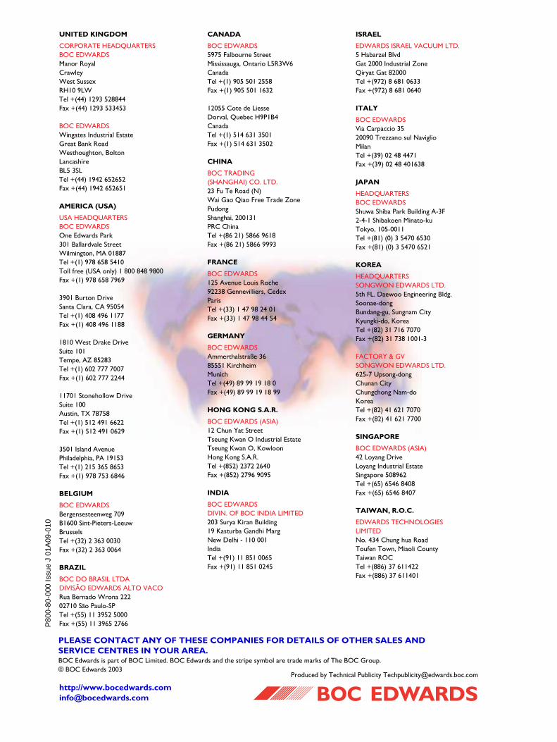
UNITED KINGDOM
CORPORATE HEADQUARTERSBOC EDWARDS Manor RoyalCrawleyWest Sussex RH10 9LWTel +(44) 1293 528844Fax +(44) 1293 533453
BOC EDWARDSWingates Industrial EstateGreat Bank RoadWesthoughton, BoltonLancashireBL5 3SLTel +(44) 1942 652652Fax +(44) 1942 652651
AMERICA (USA)
USA HEADQUARTERSBOC EDWARDSOne Edwards Park301 Ballardvale StreetWilmington, MA 01887Tel +(1) 978 658 5410Toll free (USA only) 1 800 848 9800Fax +(1) 978 658 7969
3901 Burton DriveSanta Clara, CA 95054Tel +(1) 408 496 1177Fax +(1) 408 496 1188
1810 West Drake DriveSuite 101Tempe, AZ 85283Tel +(1) 602 777 7007Fax +(1) 602 777 2244
11701 Stonehollow DriveSuite 100Austin, TX 78758Tel +(1) 512 491 6622Fax +(1) 512 491 0629
3501 Island AvenuePhiladelphia, PA 19153Tel +(1) 215 365 8653Fax +(1) 978 753 6846
BELGIUM
BOC EDWARDSBergensesteenweg 709B1600 Sint-Pieters-LeeuwBrusselsTel +(32) 2 363 0030Fax +(32) 2 363 0064
BRAZIL
BOC DO BRASIL LTDADIVISÃO EDWARDS ALTO VACORua Bernado Wrona 22202710 São Paulo-SPTel +(55) 11 3952 5000Fax +(55) 11 3965 2766
CANADA
BOC EDWARDS5975 Falbourne StreetMississauga, Ontario L5R3W6CanadaTel +(1) 905 501 2558Fax +(1) 905 501 1632
12055 Cote de LiesseDorval, Quebec H9P1B4CanadaTel +(1) 514 631 3501Fax +(1) 514 631 3502
CHINA
BOC TRADING (SHANGHAI) CO. LTD.23 Fu Te Road (N)Wai Gao Qiao Free Trade ZonePudongShanghai, 200131PRC ChinaTel +(86 21) 5866 9618Fax +(86 21) 5866 9993
FRANCE
BOC EDWARDS125 Avenue Louis Roche92238 Gennevilliers, CedexParisTel +(33) 1 47 98 24 01Fax +(33) 1 47 98 44 54
GERMANY
BOC EDWARDSAmmerthalstraße 3685551 KirchheimMunichTel +(49) 89 99 19 18 0Fax +(49) 89 99 19 18 99
HONG KONG S.A.R.
BOC EDWARDS (ASIA)12 Chun Yat StreetTseung Kwan O Industrial EstateTseung Kwan O, KowloonHong Kong S.A.R.Tel +(852) 2372 2640Fax +(852) 2796 9095
INDIA
BOC EDWARDSDIVIN. OF BOC INDIA LIMITED203 Surya Kiran Building19 Kasturba Gandhi MargNew Delhi - 110 001IndiaTel +(91) 11 851 0065Fax +(91) 11 851 0245
ISRAEL
EDWARDS ISRAEL VACUUM LTD.5 Habarzel BlvdGat 2000 Industrial ZoneQiryat Gat 82000Tel +(972) 8 681 0633Fax +(972) 8 681 0640
ITALY
BOC EDWARDSVia Carpaccio 3520090 Trezzano sul NaviglioMilanTel +(39) 02 48 4471Fax +(39) 02 48 401638
JAPAN
HEADQUARTERSBOC EDWARDSShuwa Shiba Park Building A-3F2-4-1 Shibakoen Minato-kuTokyo, 105-0011Tel +(81) (0) 3 5470 6530Fax +(81) (0) 3 5470 6521
KOREA
HEADQUARTERSSONGWON EDWARDS LTD.5th FL. Daewoo Engineering Bldg.Soonae-dongBundang-gu, Sungnam CityKyungki-do, KoreaTel +(82) 31 716 7070Fax +(82) 31 738 1001-3
FACTORY & GVSONGWON EDWARDS LTD.625-7 Upsong-dongChunan CityChungchong Nam-doKoreaTel +(82) 41 621 7070Fax +(82) 41 621 7700
SINGAPORE
BOC EDWARDS (ASIA)42 Loyang DriveLoyang Industrial EstateSingapore 508962Tel +(65) 6546 8408Fax +(65) 6546 8407
TAIWAN, R.O.C.
EDWARDS TECHNOLOGIES LIMITEDNo. 434 Chung hua RoadToufen Town, Miaoli CountyTaiwan ROCTel +(886) 37 611422Fax +(886) 37 611401
http://[email protected]
PLEASE CONTACT ANY OF THESE COMPANIES FOR DETAILS OF OTHER SALES AND SERVICE CENTRES IN YOUR AREA.BOC Edwards is part of BOC Limited. BOC Edwards and the stripe symbol are trade marks of The BOC Group.© BOC Edwards 2003
Produced by Technical Publicity [email protected]
P80
0-80
-000
Issu
e J
01A
09-0
10