Embed Size (px)
Citation preview

Institute of Fisheries Management
Fish Pass Manual:
Guidance Notes On The Legislation, Selection and Approval Of
Fish Passes In England And Wales
This manual was first prepared by the Environment Agency. Any questions
or queries should be directed to your local Environment Agency Office.
Authors:
Greg S Armstrong
Miran W Aprahamian
G Adrian Fewings
Peter J Gough
Nigel A Reader
Paul V Varallo

2

3
Table of Contents
TABLE OF CONTENTS .......................................................................................................................................... 2 LIST OF FIGURES ................................................................................................................................................ 6 LIST OF TABLES .................................................................................................................................................. 9
INTRODUCTION .............................................................................................................................................. 10
DEFINITION OF A FISH PASS .............................................................................................................................. 10 PURPOSE OF A FISH PASS .................................................................................................................................. 10
LEGISLATION .................................................................................................................................................. 11
GENERAL .......................................................................................................................................................... 11 OVERVIEW OF FISH PASS APPROVAL LEGISLATION .......................................................................................... 11 SUMMARY OF RESPONSIBILITIES AND POWERS IN RELATION TO FISH PASSES UNDER THE SAFFA 1975 (AS
AMENDED BY SCHEDULE 15 TO THE ENVIRONMENT ACT 1995). ....................................................................... 11 Fish Passes on Fishing Mill Dams .............................................................................................................. 11 Fish Passes on New or Rebuilt Weirs .......................................................................................................... 12 Fish Passes on Existing Weirs ..................................................................................................................... 12 Powers of Approval ..................................................................................................................................... 12 Protection of structure and operation of fish passes .................................................................................... 13 Compensation to Fishery Owners ................................................................................................................ 13 Fish Pass Construction ................................................................................................................................ 13 Fish pass maintenance ................................................................................................................................. 14
SUMMARY OF RESPONSIBILITIES AND POWERS IN RELATION TO FISH PASSES UNDER THE THE EELS (ENGLAND
AND WALES) REGULATIONS 2009 ..................................................................................................................... 14 Application to obstructions and reporting of obstructions .......................................................................... 14 Eel passes where passage is being impeded ................................................................................................ 14 Powers of the Agency ................................................................................................................................... 14 Notices and Appeals ..................................................................................................................................... 14
ADDITIONAL POWERS FOR FISH PASS CONSTRUCTION AND APPROVAL UNDER THE LAND DRAINAGE ACT 1991
(AND WATER RESOURCES ACT 1991). .............................................................................................................. 15 WATER RESOURCES ACT 1991 ......................................................................................................................... 15
Requiring fish passes or screens with Impoundment, or Abstraction or (Full or Transfer) licences .......... 15 Compulsory Purchase .................................................................................................................................. 16 Impoundment Licences................................................................................................................................. 16 Abstraction Licences .................................................................................................................................... 16
ENVIRONMENT ACT 1995 (AND WILDLIFE & COUNTRYSIDE ACT 1981) .......................................................... 17 Conservation Duties .................................................................................................................................... 17 Recreation Duties ........................................................................................................................................ 17 Sites of Special Scientific Interest ................................................................................................................ 17 Sustainable Development ............................................................................................................................. 18 Regard to Costs and Benefits ....................................................................................................................... 18
EC DIRECTIVES ................................................................................................................................................. 19 Formal Environmental Assessments ............................................................................................................ 19 Planning regulations .................................................................................................................................... 19 Special Areas of Conservation (SACs) ......................................................................................................... 19
OTHER LEGISLATION ........................................................................................................................................ 20 Transport & Works Act 1992 ....................................................................................................................... 20 Private Bills ................................................................................................................................................. 21 Government Bills ......................................................................................................................................... 21
NATIONAL FISH PASSAGE PANEL (NFPP) ............................................................................................... 22
ROLE OF FISH PASSAGE PANEL ......................................................................................................................... 22 RATIONALE ....................................................................................................................................................... 22 MEMBERS OF PANEL AND REPORTING LINKS .................................................................................................... 22 OVERVIEW OF OPERATION ................................................................................................................................ 23 PERFORMANCE MEASURE AND STANDARDS OF SERVICE .................................................................................. 24

4
FISH PASS APPROVAL ................................................................................................................................... 25
APPROVAL PROCESS ......................................................................................................................................... 25 Concept ........................................................................................................................................................ 25 Treatment of Applications for Approval ...................................................................................................... 25 Approval Application ................................................................................................................................... 26 Provisional Approval ................................................................................................................................... 26 Modified Approvals & Abolishments ........................................................................................................... 26 Final Approval ............................................................................................................................................. 27 Final Approval (where PA granted) ............................................................................................................ 27
A RISK BASED APPROACH TO PROVISIONAL OR FINAL APPROVAL ................................................................... 27 APPROVAL CRITERIA ........................................................................................................................................ 28
Distinction Between New and Existing Structures ....................................................................................... 28 Key Features ................................................................................................................................................ 29
FISH PASS CONSTRUCTION – THE PROJECT PROCESS ..................................................................... 33
THE PROJECT .................................................................................................................................................... 33 IDENTIFY THE SOLUTION ................................................................................................................................... 36 IDENTIFY THE TYPE OF PASS OR EASEMENT - THE CONCEPT STAGE ................................................................. 37 OUTLINE DESIGN - THE FEASIBILITY STAGE ..................................................................................................... 37 MAINTENANCE .................................................................................................................................................. 40 MONITORING .................................................................................................................................................... 40 FISH PASS COSTS .............................................................................................................................................. 41
FISH PASS SELECTION .................................................................................................................................. 42
BIOLOGICAL FACTORS ...................................................................................................................................... 42 Migration and types of migrant ................................................................................................................... 42 Reasons for Migrating and Consequences of not doing so .......................................................................... 44 Species Factors ............................................................................................................................................ 44 General Considerations ............................................................................................................................... 45
SPECIES APPLICABILITY .................................................................................................................................... 46 FISH BEHAVIOUR .............................................................................................................................................. 46
Time of migration ......................................................................................................................................... 46 Diurnal ......................................................................................................................................................... 46 Sexual maturity / condition .......................................................................................................................... 47 Temperature ................................................................................................................................................. 47 River flow ..................................................................................................................................................... 47
SWIMMING PERFORMANCE ................................................................................................................................ 48 Swimming Speeds ......................................................................................................................................... 48 Some Simple Swimming Speed Criteria for Fish Passes .............................................................................. 56 Location and Attraction ............................................................................................................................... 56 Choice of Location at an Obstruction .......................................................................................................... 57 Flow Conditions at the Entrance ................................................................................................................. 58 Discharge from the Fishway ........................................................................................................................ 58 Fish Pass Selection Matrix .......................................................................................................................... 59
FISH PASS TYPES ............................................................................................................................................ 62
POOL PASSES .................................................................................................................................................... 62 General ........................................................................................................................................................ 62 Pool & Weir or Pool & Traverse ................................................................................................................. 67 Vertical Slot ................................................................................................................................................. 69 Pool & Orifice ............................................................................................................................................. 74 Deep Notch & Submerged Orifice ............................................................................................................... 76 Ice Harbor ................................................................................................................................................... 78 Pool & Chute ............................................................................................................................................... 80 Shallow 'V' Notch Weirs ............................................................................................................................... 82
BAFFLE FISHWAYS ............................................................................................................................................ 84 General ........................................................................................................................................................ 84

5
Side & Bottom Baffle Fishways ................................................................................................................... 87 Plane Baffle Denils ...................................................................................................................................... 87 Fatou Denils ................................................................................................................................................ 93 Alaskan 'A' Denils ........................................................................................................................................ 97 Bottom Baffle Fishways ............................................................................................................................. 100 Super-active baffle (Larinier) pass ............................................................................................................ 100 Chevron baffles .......................................................................................................................................... 106 Side Baffle Fishways .................................................................................................................................. 111 Chevron Side Baffles .................................................................................................................................. 112 Brush-furnished Fishway & Canoe-Fishway ............................................................................................. 115
ACTIVE FISH ELEVATORS ............................................................................................................................... 118 Fish Locks .................................................................................................................................................. 118 Fish Lifts .................................................................................................................................................... 121 Venturi Pump Fishway ............................................................................................................................... 122
NON-TECHNICAL FISH PASSAGE SOLUTIONS .................................................................................... 124
STREAMING FLOW AND HETEROGENEOUS CONDITIONS .................................................................................. 124 ADHERENT (NON-AERATED) NAPPES ............................................................................................................... 125 NOTCHES AND GAPS OR SLOTS ....................................................................................................................... 126 BAULKS .......................................................................................................................................................... 128 BAFFLE SYSTEMS ............................................................................................................................................ 130 HURN-TYPE BAFFLE SYSTEM FOR FLAT V WEIRS ............................................................................................ 131 LOW COST BAFFLE (LCB) SOLUTION FOR CRUMP-TYPE AND SLOPING WEIRS ................................................ 135 PRELIMINARY WEIRS (PRE-BARRAGES, CHECK WEIRS) ................................................................................. 137 MODIFICATIONS TO THE NATURAL BED .......................................................................................................... 139 ROCK RAMPS .................................................................................................................................................. 140 SWEEPS ........................................................................................................................................................... 144 ARTIFICIAL RIVER CHANNELS ........................................................................................................................ 146 PASSAGE IN CULVERTS AND OTHER RIVER CROSSINGS .................................................................................. 148
General ...................................................................................................................................................... 148 New Culverts .............................................................................................................................................. 148 Existing Culverts ........................................................................................................................................ 153 Simple Baffles ............................................................................................................................................ 153 Off-set Baffles ............................................................................................................................................ 156 Screening of Culverts and Other Openings ............................................................................................... 161 Tidal Flap Gates ........................................................................................................................................ 164
ANGUILLIFORM PASSES ............................................................................................................................ 169
GENERAL ........................................................................................................................................................ 169 CLOSED TYPE EEL PASSES ............................................................................................................................... 172 OPEN TYPE EEL PASSES ................................................................................................................................... 172 MONITORING .................................................................................................................................................. 176 LAMPREY PASSAGE ......................................................................................................................................... 178
ADDITIONAL FACILITIES .......................................................................................................................... 180
RESTING FACILITIES ........................................................................................................................................ 180 PROTECTION FROM DEBRIS ............................................................................................................................. 181 LIGHTING ........................................................................................................................................................ 183 AUXILIARY FLOW ........................................................................................................................................... 184 TRAPS ............................................................................................................................................................. 184 FACILITATING MONITORING ........................................................................................................................... 188 FISH COUNTERS ............................................................................................................................................... 190 CONJUNCTIVE USE BY CANOES ........................................................................................................................ 190
FISH PASSAGE AT GAUGING STATIONS ............................................................................................... 192
CRUMP WEIRS (INCLUDING COMPOUND CRUMP WEIRS) ................................................................................. 192 FLAT V WEIRS ................................................................................................................................................ 197 APPROACH CONDITIONS TO GAUGING WEIRS ................................................................................................. 197
6
GUIDELINES FOR NEW CRUMP AND FLAT V GAUGING STATIONS ................................................................... 198 OTHER GAUGING STRUCTURES ....................................................................................................................... 199 INTERNATIONAL STANDARD (ISO) & BRITISH STANDARD (BS) COMPOUND GAUGING & FISH PASS
STRUCTURES ................................................................................................................................................... 200 IMPROVEMENTS AT EXISTING STRUCTURES ..................................................................................................... 205
FISH PASSAGE AT WATER CONTROL STRUCTURES & NAVIGATION LOCKS .......................... 208
SLUICES AND RADIAL GATES ........................................................................................................................... 208 UNDERSHOT SLUICES ...................................................................................................................................... 208 OVERSHOT SLUICES ........................................................................................................................................ 211 RADIAL GATES ................................................................................................................................................ 213 NAVIGATION LOCKS ....................................................................................................................................... 213
FISH PASS EVALUATION AND MAINTENANCE ................................................................................... 215
THE NEED FOR MONITORING THE PERFORMANCE OF A FISH PASS .................................................................... 215 Introduction ............................................................................................................................................... 215 Some reasons for undertaking evaluation .................................................................................................. 217 The requirements for monitoring ............................................................................................................... 218 Cumulative effect of a number of structures .............................................................................................. 219 Relative position and importance of the obstruction within the catchment ............................................... 221 Conclusion ................................................................................................................................................. 225
FISH PASS MAINTENANCE ............................................................................................................................... 226 Legal Position ............................................................................................................................................ 226 Inspection ................................................................................................................................................... 227
REFERENCES ................................................................................................................................................. 230
KEY REFERENCES ........................................................................................................................................... 230 SPECIFIC REFERENCES .................................................................................................................................... 231 ACKNOWLEDGEMENTS .................................................................................................................................... 240
APPENDICES ................................................................................................................................................... 242
APPENDIX I MANUAL FEEDBACK FORM ...................................................................................................... 242 APPENDIX II LEGISLATION .......................................................................................................................... 243 APPENDIX III NATIONAL FISH PASSAGE PANEL TERMS OF REFERENCE ...................................................... 256 APPENDIX IV CONCEPT FORM ..................................................................................................................... 257 APPENDIX V RISK MATRICES ...................................................................................................................... 259 APPENDIX VI DRAFT APPLICATION FOR FISH PASS APPROVAL FORM ........................................................ 263 APPENDIX VII TYPICAL LIST OF REQUIREMENTS FOR A FEASIBILITY STUDY ............................................. 288 APPENDIX VIII EXAMPLES OF COST BENEFIT ANALYSIS............................................................................. 290 APPENDIX IX SCALING FACTORS FOR THE HURN BAFFLE SOLUTION FOR FLAT V WEIRS ......................... 315 APPENDIX X GLOSSARY OF TERMS ............................................................................................................. 316 APPENDIX XI SOME TYPICAL HYDRAULIC EQUATIONS ............................................................................... 323 APPENDIX XII FISH PASS INSPECTION FORM ............................................................................................... 330 APPENDIX XIII LIST OF ABBREVIATIONS ..................................................................................................... 333 APPENDIX XIV MONITORING PROGRAMME EXAMPLES .............................................................................. 335 APPENDIX XV SYMBOLS USED IN THE TEXT .............................................................................................. 347 APPENDIX XVI DRAFT GUIDANCE NOTE: EEL PASSES AT GAUGING STRUCTURES...................................... 352

7
List Of Figures
Figure 1Flow summarising the stages and inputs to a fish passage improvement project part 1 ........................ 33
Figure 2 Flow diagram summarising the stages and inputs to a fish passage improvement project part 2 ........ 34
Figure 3 Schematic illustration of the swimming speeds of a particular species (After Clay, 1995). .................. 49
Figure 4 Maximum swimming speed in relation to fish length and temperature (After Beach, 1984) ................. 51
Figure 5 Endurance at maximum swimming speeds in relation to fish length and temperature (After Beach,
1984) ...................................................................................................................................................... 51
Figure 6 Swimming speed and endurance for different sizes of fish at different temperatures (After Larinier,
1992b) .................................................................................................................................................... 52
Figure 7 Maximum swimming distance attainable at different water velocities and temperatures for two lengths
of salmonid (After Larinier, 1992b) ....................................................................................................... 52
Figure 8 Plunging and streaming flow passes (After Larinier, 1992a). ............................................................... 63
Figure 9 Schematic diagram of a typical Pool & Traverse fish pass with notched traverse and plunging type
flow. Dimensions given are the recommended minima for large migratory salmonids (After Beach,
1984 & Larinier 1992a). ........................................................................................................................ 68
Figure 10 Single and paired vertical slot passes (after Larinier, 1992a) ............................................................. 71
Figure 11 Details of designs of vertical slot pass tested by Rajaratnam, Katapodis and Solanki (After
Rajaratnam et al 1992) (a) ..................................................................................................................... 72
Figure 12 Details of designs of vertical slot pass tested by Rajaratnam, Katapodis and Solanki (After
Rajaratnam et al 1992) (b) ..................................................................................................................... 73
Figure 13 Pool and orifice fishway (After Rajaratnam, Katopodis & Mainali, 1989 and Larinier 1992a) ......... 75
Figure 14 Characteristics of some deep slot and orifice passes used in France (After Larinier, 1992a). ........... 77
Figure 15 Characteristics of an Ice Harbor pass (after Larinier, 1992a) ............................................................ 79
Figure 16 Characteristics of a Pool & Chute fishway (after Bates, 1990) ........................................................... 81
Figure 17 Characteristics of a V-shaped pool fishway used in the Netherlands (after Boiten 1990)................... 83
Figure 18 Idealised profile for the head of the pass and intermediate rest pools for baffle passes ..................... 86
Figure 19 Cross-section and geometric characteristics of a plane baffle Denil fishway (After Larinier 1992d) 88
Figure 20 Isometric view of a plane baffle Denil fishway (After Beach, 1984) .................................................... 89
Figure 21 Dimensionless relationship between upstream head (ha), mean depth in pass (h), discharge (Q), and
velocity (V) in a plane baffle fishway at 10, 15 & 20% slopes (After Larinier 1992d) .......................... 91
Figure 22 Relationship between between upstream head (ha), mean depth in pass (h), discharge (Q), and
velocity (V) in plane baffle fishways 0.6 & 0.9m wide at 20% slopes (After Larinier 1992d) ............... 92
Figure 23 Cross-section and plan view of a Fatou baffle fishway (After Larinier, 1992d) .................................. 94
Figure 24 Adimensional relationship between upstream head (ha), mean depth in pass (h), discharge (Q*), and
velocity (V) in a Fatou baffle fishway at 10, 15 and 20% slopes (After Larinier, 1992d) ...................... 95
Figure 25 Relationship between between upstream head (ha), mean depth in pass (h), discharge (Q), and
velocity (V) in Fatou baffle fishways 0.6 & 0.9m wide at 20% slopes (After Larinier, 1992d) .............. 96
Figure 26 Plan and cross-section, giving the geometric characteristics of an Alaskan `A` fishway (After
Larinier, 1992d) ..................................................................................................................................... 98
Figure 27 Isometric view of an Alaskan `A` fishway (After Larinier, 1992d) ...................................................... 98
8
Figure 28 Geometric characteristics of a Super-active baffle (Larinier) fish way (After Larinier, 1992d) ....... 101
Figure 29 Isometric view of a Super-active baffle (Larinier) fishway ................................................................ 101
Figure 30 Dimensionless relationship between upstream head (ha), mean depth in pass (h), unitary discharge
(q*), and the average water velocity (V*) in a Super-active baffle fishway at 10% and 15% slopes
(After Larinier 1992d) .......................................................................................................................... 103
Figure 31 Relationship between upstream head (ha), mean depth in pass (h), unitary discharge (q), and velocity
(v) for 0.10m & 0.15m high super-active baffle fishways at 15% slope (After Larinier 1992d) ......... 104
Figure 32 Geometric characteristics of a Chevron baffle fishway (After Larinier 1992d) ................................ 107
Figure 33 Dimensionless relationship between upstream head (ha), mean depth in pass (h), unitary discharge
(q*), and velocity (V*) in a Chevron baffle fishway at 10% and 15% slopes (After Larinier, 1992d) . 109
Figure 34 Relationship between upstream head (ha), mean depth in pass (h), unitary discharge (q*), and
velocity (V*) for a 0.10m high chevron baffle fishway at a 15% slope (After Larinier, 1992d) ........... 110
Figure 35 Geometric characteristics of a Chevron Side Baffle fishway (After Larinier & Miralles, 1981)....... 113
Figure 36 Dimensionless relationship between upstream head (ha), mean depth in pass (h), and discharge (q) in
a Chevron side baffle fishway at 10%, 15% and 20% slopes (After Larinier & Miralles, 1981)......... 114
Figure 37 Head discharge relationship for a fishway with 47cm long bristles (after Hassinger & Kraetz, 2006)
.............................................................................................................................................................. 116
Figure 38 The plan and cross-section of a typical fish lock (after Aitken et al, 1996) ....................................... 119
Figure 39 The operating cycle of a fish lock (after Travade & Larinier, 1992a) ............................................... 120
Figure 40 Typical layout of the FishFlow venturi pass (after FishFlowInnovations) ........................................ 123
Figure 41 Chamfered profile for an adherent nappe .......................................................................................... 126
Figure 42 Schematic diagram of a Baulk pass (after Fort & Brayshaw, 1961) ................................................. 129
Figure 43 Characteristics of the Hurn-type baffle system (After Walters, 1996) ............................................... 132
Figure 44 Velocities on a Flat V gauging weir fitted with Hurn-type baffles ..................................................... 133
Figure 45 General arrangement of the Low Cost Baffle solution at field scale, in plan and elevation & showing
cross-sectional details .......................................................................................................................... 136
Figure 46 Schematic plans illustrating the use of pre-barrages across the whole, or part of the width, of a
stream in front of a barrier (after Larinier, 1992a) ............................................................................. 138
Figure 47 The general design layout of experimental rock-ramp fishways in New South Wales, Australia (after
Harris et al, 1998) ................................................................................................................................ 142
Figure 48 Plan view of a fish ramp in the corner of a weir on the Elz River, Germany (after Gebler, 1998) ... 142
Figure 49 Schematic diagram of a `through dam sweep` (after Hyldegaard & Peterson, 1999)....................... 145
Figure 50 Asymetric arrangement of a sweep fishpass (courtesy of Atkins plc.) ............................................... 145
Figure 51 Examples of culvert types................................................................................................................... 152
Figure 52 Baffle designs for barrel culverts (After Bates, 1992) ....................................................................... 154
Figure 53 Rectangular, triangular, and slotted baffle systems (After Larinier, 2002). ..................................... 154
Figure 54 Geometric characteristics of the off-set baffle (After McKinley & Webb, 1956) ................................ 155
Figure 55 Chevron culvert baffle design detail for Grwylech Culvert, Afon Grwylech, SW Wales. ................. 158
Figure 56 Detail of a Montana bed-load collector (After Belford & Gould, 1989) ........................................... 160
Figure 57 Typical configuration of a culvert pre-barrage ................................................................................. 160
Figure 58 Baffle system in use at road bridges in North East England.............................................................. 163
Figure 59 Gap and flow for a 4-foot (1.2m) cast iron flap gate (After Bates, 1997) .......................................... 166

9
Figure 60 Gap and flow for a 4-foot (1.2m) aluminium flap gate (After Bates, 1997) ....................................... 166
Figure 61 Operating sequence of the SRT Gate (courtesy of Waterman Industries Inc).................................... 168
Figure 62 Various configurations of eel pass (after Knights & White, 1998) .................................................... 171
Figure 63 Schematic plan of a fishway for elvers and small eels (after Porcher,1992) .................................... 174
Figure 64 Typical specification of brush boards for eel passes ......................................................................... 174
Figure 66 Typical configuration of a pass and trap for elvers and young eels (After Porcher, 1992) ............... 177
Figure 67 Schematic examples of laterally sited fishway exits to help avoid trash problems (after Larinier,
1992c) ................................................................................................................................................... 182
Figure 68 Schematic plan of a trapping area showing minimum dimensions (adapted after Travade & Larinier,
1992a) .................................................................................................................................................. 186
Figure 69 Some typical configurations in plan view of video monitoring arrangements in Larinier, Denil, and
Vertical Slot passes .............................................................................................................................. 189
Figure 70 Schematic diagram of a crump flow gauging weir with upstream and downstream slopes of 1:2 and
1:5 respectively (After Crump,1952) .................................................................................................... 193
Figure 71 Mean water velocity at various distances Z from the crest of a Crump weir plotted against upstream
head (After Beach, 1984) ...................................................................................................................... 193
Figure 72 Schematic diagram of a compound Crump weir showing the low flow section that provides a fishway
and a high crest section for high flows. Note the automatic fish-counting electrodes on the weir face
(after Beach 1984 & Bussell, 1978). .................................................................................................... 196
Figure 73 Schematic diagram of a Flat V gauging weir (After Beach, 1984) .................................................... 196
Figure 74 General arrangement of a compound gauging structure with Larinier fish pass alongside a Crump
Weir ...................................................................................................................................................... 202
Figure 75 Hydrometric standard discharge relationship for a Larinier super-active baffle pass with 100mm
baffles. .................................................................................................................................................. 203
Figure 76 Undershot sluices with flow regulated by multiple gates, permitting low discharges to be achieved
while providing suitable conditions for fish passage (After Beach, 1984) ........................................... 209
Figure 77 A single large undershot gate controlling flow (often automated).A low discharge results in an
impassable high velocity jet (After Beach, 1984) ................................................................................. 209
Figure 78 This form of undershot sluice is very unsuitable. The base block enables a water jet to form, while the
flat base allows the high velocity to persist over a considerable distance (After Beach, 1984) ........... 210
Figure 79 Fish passage at this form of undershot sluice is much easier. The lack of obstruction below the sluice
gate and graded approach to the stilling basin allow rapid attenuation of water velocity (After Beach,
1984) .................................................................................................................................................... 210
Figure 80 Overspill sluice with sharp edge and shallow water over concrete apron; this produces difficult
approach conditions for fish because of insufficient downstream water depth (After Beach, 1984) ... 212
Figure 81 Overspill sluice with curved edge and stilling basin; this produces sufficient water depth for an easy
approach and a smooth crest flow (After Beach, 1984) ....................................................................... 212
Figure 82 Effects of fish passage efficiency in river systems where a series of passes are constructed along the
migratory route for salmonids (After Gowans, 1998) .......................................................................... 220

10
List Of Tables
Table 1 Approximate guide to fish pass costs ....................................................................................................... 42
Table 2 Examples of Swimming speeds for some UK fish of 15cms fork length at 10C and eel of 30cms at 15°C
(SWIMIT version3_3 Nov 2006) ............................................................................................................. 53
Table 3 Swimming capabilities of shad (0.30 to 0.50 m in length) from Larinier (1996). .................................... 54
Table 4 Some simple guidelines for basic parameters of pool, and baffle, fish passes ........................................ 56
Table 5 Framework used in the initial planning phase to describe the approximate dimensions in terms of slope,
discharge and maximum mean velocities in nature like by-passes in Austria (After Parasieewicz et al,
1998) .................................................................................................................................................... 147
Table 6 Design criteria for culverts to enable fish to pass (Adapted after Scottish Executive, 2000) ................ 150
Table 7 Guidelines for the sizing of trapping areas ........................................................................................... 185
Table 8 Numerical values for hydrometric standard discharge relationship for a Larinier super-active baffle
pass with 100mm baffles....................................................................................................................... 204
Table 9 Efficiency of various fish passes for salmon .......................................................................................... 216
Table 10 The relative merits of the main methods that can be used to monitor the effectiveness of a fish pass . 223
Table 11 The relative merits of the main methods that can be used to monitor the efficiency of a fish pass...... 224
Table 12 Risk assessment for maintenance requirement of a fish pass .............................................................. 228

INTRODUCTION
Definition of a Fish Pass
A fish pass is not defined in the legislation. For the purposes of this manual a fish pass is defined as:
Any form of conduit, channel, lift, other device or structure which facilitates the free passage of
migrating fish over, through or around any dam or other obstruction, whether natural or man-made, in
either an upstream or a downstream direction.
In the past the provision of fish passes has usually only been concerned with the upstream migration
of the diadromous (sea to freshwater cycle) migratory salmonid species. In recent years interest has
widened to include the potadromous (within freshwater) coarse fish species, and other diadromous
species such as eels and shad. This manual seeks to encourage the consideration of fish passes for the
upstream passage of all species.
Until recently downstream migration has largely been ignored in the UK, except in so far as it was
covered for migratory salmonids by the legislation on screening water intakes. In 1999 this legislation
was strengthened and extended, although still only for the protection of migratory salmonids. Safe
downstream passage is an important issue and should not be ignored, however it is outside the scope
of this manual. For information on this aspect the reader is referred to the Environment Agency R&D
report on Screening for Intake and Outfalls: a best practice guide, Science Report SC030231 O’Keeffe
& Turnpenny, 2005), and the Environment Agency training manual on screening of intakes and
outfalls (1998).
Recently there has been an upsurge in the use of existing, and sometimes new, obstructions for the
purposes of electricity generation by hydropower. It is essential in such projects that account is taken
of fish passage needs both in the upstream and downstream directions
Purpose of a Fish Pass
The purpose of a fish pass is to allow the free passage of endemic species of the appropriate
developmental stage(s) at the appropriate time(s) of year. It may be necessary to consider the passage
of juvenile salmonids (smolts) as well as adult migratory salmonids; the needs of different life stages
of freshwater fish species, eels, lampreys and shad. If a barrage is being proposed it may also be
necessary to consider the needs of marine species such as mullet and flounder
Whilst the design of fish passes for adult migratory salmonids is well advanced, the requirements of
other species, and requirements for downstream migration of all species are not fully understood. This
manual seeks to provide a good grounding of our current knowledge but there is still extensive
research which needs to be undertaken before we can be fully confident that fish passes will always
achieve our design aims.
It is worth bearing always in mind that fish are animals, not automatons, and individuals have a wide
range of abilities, just as humans do. Fishways should be designed to allow all individuals in a
population to have the chance to pass, and not just the `atheletes` among them.

12
LEGISLATION
General
Statutory responsibility for the approval of fish passes for migratory salmonids lies with the
Environment Agency under the Salmon and Freshwater Fisheries Act 1975 (‘SAFFA’). The
responsibility was transferred from the Ministers of the Environment, England; Secretary of State,
Wales under Section 105 of, and Schedule 15 to the Environment Act 1995 and became effective
upon the formation of the Agency on 1st April 1996. Statutory responsibility for the approval of passes
for eels also lies with the Environment Agency under The Eels (England and Wales) Regulations
2009, which came in to force on 15th January 2010. This Statutory Instrument implements Council
Regulation (EC) No 1100/2007 that established measures for the recovery of the stock of European
eel.
In addition when considering construction there are a number of other legislative requirements that
need to be taken into account. An appropriate environmental assessment should be undertaken as with
all other construction projects. Fish passes are also likely to require Land Drainage Consent under the
provisions of the Land Drainage Act 1991 or the Water Resources Act 1991. An impoundment
licence may be required under the Water Resources Act. Plannng permission may be required under
the Town and Country Planning Act 1990. Extracts of relevant Legislation is given in Appendix II.
Overview of Fish Pass Approval Legislation
The application of fish pass approval legislation is currently confined to watercourses, which are
frequented by migratory salmonids (ie salmon, sea trout) and eel. It does not apply to waters, which
do not contain migratory salmonids or eel.
Summary of responsibilities and powers in relation to fish passes
under the SAFFA 1975 (as amended by Schedule 15 to the
Environment Act 1995).
Fish Passes on Fishing Mill Dams
Section 8 of the SFFA refers to fishing mill dams. This section makes it a condition that such a dam
cannot be used to take migratory salmonids unless it has an Agency approved fish pass attached to it -
S 8(2). In fact in practice the Agency is not aware of the existence of any such structures, and this
section is to be repealed by the Marine & Coastal Access Act 2009 with the repeal due to take effect
from January 2011.
Fish Passes on New or Rebuilt Weirs
Section 9 of the SFFA allows the Agency to serve notice on the owner or occupier of a dam or
obstruction, to install a fish pass where necessary. Where notice is served the owner or occupier of the
dam or obstruction has a duty to make a fish pass within a reasonable time as specified in the notice

13
and subject to such form and dimensions as the Agency may approve and thereafter to maintain the
pass in an efficient state. The fish pass details are now approved by the Agency, rather than the
Minister or Secretary of State as previously - S9(1). This section applies to dams which are either new
or have been altered to create an increased obstacle to the passage of migratory salmonids. It is also
applicable where dams in a state of disrepair have been rebuilt over at least one half of their length.
This section also allows the Agency to enter on any dam or land adjoining, carry out any works
necessary to install or maintain a fish pass and gives the Agency powers to recover the costs of these
works - S9(3).
The important change within this section of the Act is the transfer of the responsibility for approval of
the "form and dimensions" of fish passes for salmon and migratory trout, from the Minister, or
Secretary of State, to the Agency. Except for the substitution of the "Agency" for the "NRA", the
remainder of this Section is unaltered. It should be noted that this section applies only to waters
frequented by salmon and migratory trout and to passes for those species only. (Section 156 of the
Water Resources Act 1991 gives the Agency additional powers to purchase land and property
associated with dams and fish passes in relation to both this Section, and Section 10 below.)
Fish Passes on Existing Weirs
Section 10 allows the Agency to build or alter fish passes on dams at its own discretion and at its own
expense. There is no longer a requirement for the relevant Minister to approve the form and
dimensions of fish passes built under this section; this is now left to the Agency to determine - S
10(1). This section also allows the Agency to abolish, alter or restore to its former state of efficiency,
any existing fish pass or free gap, or to substitute another fish pass or free gap. Again, there is no
longer a need for Ministerial consent for such alterations - the Agency may make its own decisions in
such matters - S10(2). Works carried out in this section should not jeopardise the operation of certain
specified interests, which may be connected with structures altered by the Agency. The final
subsection gives the Agency the power to recover costs incurred in repairing a damaged pass - S10(3).
Unlike Section 9, this section contains no caveats referring to ‘waters frequented by salmon or
migratory trout’. Arguably, therefore, it provides the Agency with the power to construct fish passes
for any fish species in any waters
Powers of Approval
Section 11 gives a number of powers to the Agency which were formerly exercised by the appropriate
Minister. As the approving body, the Agency can issue provisional approval for a fish pass, until it is
satisfied that the pass is working properly - S 11(1). In a new subsection, the Act makes it a condition
that an applicant for fish pass approval will be liable for any costs incurred in determining whether or
not a fish pass is working satisfactorily – S11(1A)(b).
This new subsection also makes it a condition that the applicant must supply the Agency with any
information or assistance it needs to show that the pass is working properly - S 11(1A)(b). The
Agency may revoke any provisional approval, provided that the applicant is given at least 90 days'
notice - S 11(2) - and where approval is revoked, the Agency may extend the period within which the
fish pass is to be constructed - S 11(3). The Agency may give approval to any fish pass, if it considers
such a pass to be operating properly, whether the pass has been built under this Act or not - S 11(4).

14
Where a pass has received final approval, then it is deemed to be in conformity with this Act, whether
or not it was built in the manner or by the person specified in this Act - S 11(5).
Protection of structure and operation of fish passes
Section 12(1)(2) makes it an offence for owners of passes or any person to alter or damage a fish pass,
or otherwise do anything that prevents or deters the passage of salmon and trout through a fish pass,
or to take fish passing through. It provides powers – S12(2) - for the Agency to serve notice on the
owner or occupier of a dam to repair a fish pass. A pass is deemed to be altered if it is damaged,
destroyed or allowed to fall into dis-repair.
Compensation to Fishery Owners
Section 17 deals mostly with the restrictions applied to the taking or disturbing of salmonids in the
vicinity of dams, obstructions or mill races. This section also makes it a condition that these
restrictions will not apply until any necessary compensation has been made by the Agency, to anyone
with commercial fishing rights which may be affected by the installation of a pass - S 17(3). This
section is to be repealed by the Marine & Coastal Access Act 2009, with the repeal due to take effect
from January 2011.
Fish Pass Construction
Section 18 makes additional provisions to the above sections. In particular, this section makes it an
offence for anyone to obstruct a legally authorised person from carrying out any act authorised under
Sections 9 and 10 - S 18(1). The section also makes it a condition that the Agency must give
reasonable notice to the owner or occupier of a dam or other structure, where it intends to construct,
abolish or alter any fish pass or free gap under Section 10. The Agency must supply the owner or
occupier with a plan and specification of the proposed work, and must take into consideration any
objections raised by these people before carrying out the work - S 18(2). If the Agency causes damage
to a dam in the process of constructing, altering or abolishing a fish pass or free gap under Section 10,
then the person whose interest has been affected may recover compensation from the Agency -
S18(3)(a). In the event of a disagreement over compensation under either Section 10 or 17, then a
single arbitrator shall be appointed by the appropriate Minister to settle the dispute - S18(4). Where
the Agency is liable for compensation under this Part of the Act, proceedings for the recovery of this
compensation must be started within two years of the completion of the work which was considered
to cause the damage - S18(5).
Fish pass maintenance
Where an owner or occupier has been required to make a fish pass under S9(1) they are also obliged,
under the same section, to thereafter maintain it in an efficient state. Failure to do so is an offence -
S9(2). The Agency may take remedial action, enter on the structure or adjoining land for the purpose
of taking action, and may recover the costs of so doing from the person in default - S9(3).

15
Summary of responsibilities and powers in relation to fish passes
under the Eels (England and Wales) Regulations 2009
This is a Statutory Instrument (SI) 2009 No 3344 made under Section 2(2) of the European
Communities Act 1972(b), that came in to force on 15th January 2010.
Application to obstructions and reporting of obstructions
Regulation 12 defines the types of obstruction and circumstances in which the regulations apply. It
covers new constructions, maintenance of existing structures, and the construction or maintenance of
any structure near waters that may affect passage of eels. Any such works must be notified to the
Agency. Regulation 13 requires the Agency to be notified of any new obstructions that come about
that may impeded migration (including natural or artificial events).
Eel passes where passage is being impeded
Regulation 14 allows the Agency to serve notice on the responsible person to install a fish pass, make
alterations to an existing eel pass structure, operate an eel pass in accordance with conditions, remove
an obstruction, or take any other necessary action to improve or maintain eel passage. This regulation
also gives the Agency powers to serve notice requiring the responsible person to submit plans for
approval of the pass, and to attach conditions regarding operation of the eel pass. Regulation 15
requires eel passes to be maintained, and Regulation 16 makes it an offence to interfere with or
obstruct passage of eels through a pass.
Powers of the Agency
Regulation 20 confers powers on the Agency to act in an emergency, if the responsible person cannot
be identified, or where the responsible person has not complied with a notice. Costs of any actions
may be recovered form the responsible person. Regulation 21 disapplies requirement for abstraction
or impoundment licences in respect action required or undertaken under Eel Regulations. Regulation
22 defines ‘responsible’ persons.
Notices and Appeals
Regulations 23 and 24 cover how notices must be constructed and served on a person. Regulation 25
covers rights of appeal and appeal process.
Additional powers for fish pass construction and approval under
the Land Drainage Act 1991 (and Water Resources Act 1991).
As previously noted, the Agency does not have the power under SAFFA to require the provision of
fish passes in waters not frequented by migratory salmonids. Even in migratory waters a developer
cannot be required to construct a pass, and therefore to go through the approval process, where the
barrier to migratory fish passage is not being increased or where a structure has not been taken down
for more than half its length.

16
However, in such waters, land drainage legislation may be used to make sure provision is made for fish passage. S105(3) of the Water Resources Act places a duty on the Agency in exercising its flood defence powers to have due regard to the interests of fisheries and conservation (important for species such as shad and lampreys), including sea fisheries (which may be important for species such as flounder, mullet etc). This means that, where a Flood Defence Consent is required for a structure, such consent might not be issued if the structure would impede fish migration. The Agency may then seek the installation of a suitable form of fish pass, as an integral part of the Flood Defence Consent process using either:
a) The Land Drainage Act 1991, S 23; applicable to ordinary watercourses*
b) The Water Resources Act 1991, S109; applicable to main rivers
However, it should be understood that the primary consideration of flood defence consenting relates
to efficient drainage and it is possible that fish passage considerations may not prove determinative.
Moreover, conditions cannot be currently imposed on consents under the Land Drainage Act 1991
except in in relation to time and the manner of work being carried out. This is therefore not the most
robust means for providing for fish passage.
This route may also be used to ensure the installation of a suitable fish pass if one is proposed by a
developer without having been required to do so by the Agency, when it would be otherwise outside
the powers of SAFFA.
Water Resources Act 1991
Requiring fish passes or screens with Impoundment, or Abstraction or
(Full or Transfer) licences
As noted above the Agency does not have the power under SAFFA to require the provision of fish
passes or screens in waters not frequented by migratory salmonids, and there are limitations even in
migratory salmonid waters in respect of passes.
However, in any waters where fish passage is an issue, Water Resources legislation (Sections 24 and
25 Water Resources Act 1991) may be used to make sure that provision is made for fish passage as
the Agency can impose what conditions it sees fit on abstraction or impoundment licences*. This
means that where impoundment or abstraction licences are required, and fish migration would be
impeded, conditions can be placed on the licence to install suitable forms of fish pass or screen.
* This is because the Agency has broad powers to impose conditions in abstraction or impoundment
licences under Section 38(2)(a) Water Resources Act 1991 i.e. “may grant a licence containing such
provisions as the Agency considers appropriate”. In exercising this power the Agency considers its
statutory duty under Section 6(6) of the Environment Act, 1995 as amended by the Marine and
Coastal Access Act, 2009 to ‘maintain, improve and develop fisheries for salmon, trout, eels, lamprey,
smelt and freshwater fish’. It also considers its duty to further the conservation of flora, fauna and
geological or physiographical features of special interest under Section 7(1)(a) and take account of
effects generally on flora or fauna under Section 7(1)(c)(ii) Environment Act 1995 and its principal
aim in relation to attaining objective of achieving sustainable development under Section 4
* Note that the Agency will no longer be the consenting authority once the Flood & Water Management Act 2010 provisions are brought into force.
17
Environment Act 1995. In addition the WFD Regulations 2003 require the Agency to exercise all our
functions (powers & duties) including those in WRA 1991 and SAFFA 1975 so as to secure
compliance with WFD requirements.
Compulsory Purchase
The Water Resources Act 1991 gives the Agency the ability to acquire land and other properties under
compulsory purchase to assist the process of improving fish passage either by the construction of fish
passes or by the removal of obstructions. S156 empowers the Agency to purchase or take on lease,
either by agreement or compulsorily, any dam, fishing weir fishing mill dam, fixed engine or other
artificial obstruction or any fishery connected to the structure (S156(1)(a)) This section also allows
the Agency to take land adjoining any dam where we are involved in fish pass construction or
maintenance under s10 of SAFFA (S156(1)(b)). Section 156(2) further gives us powers to remove
obstructions under certain circumstances.
Impoundment Licences
There may, in certain circumstances, be a requirement for the issuing of an impoundment licence
when a fish pass is constructed. This is particularly pertinent where new dams and weirs are being
built but is also relevant where fish passes are installed in existing structures. If the pass results in any
change in the upstream water regime, essentially water level(s), then an impoundment licence is likely
to be required. Section 25 of the Water Resources Act 1991 is applicable here and advice should be
sought from the National Permitting Service.
Abstraction Licences
Where a fish pass is constructed on a structure within the river channel, this can be done without the
need for an abstraction licence (full or transfer). However, where a fish pass is built to go round a
structure and where water is taken out of the river channel upstream of the structure and is then
returned to the river channel downstream of the structure, an abstraction (full or transfer) licence will
be required. Section 24 of the Water Resources Act is applicable here and advice should be sought
from the National Permitting Service.
Environment Act 1995 (and Wildlife & Countryside Act 1981)
Conservation Duties
In carrying out its duties the Agency has a duty to further the conservation and enhancement of
natural beauty and the conservation of flora, fauna and geological or physiographical features of
special interest under S7(1)(a) of the Environment Act. The Agency is also obliged to have regard to
the desirability of protecting buildings and archaeological features of interest, to take into account any
impact its activities may have on the beauty or amenity of any rural or urban area or on any such flora,

18
fauna, features, buildings, sites or objects and to have regard to any effect which its activities would
have on the economic and social well-being of local communities in rural areas.- S7(1)(c). These
responsibilities are particularly pertinent where fish passes are being constructed in weirs of historic
interest, or in natural barriers. (While it can generally be argued that the benefits derived for fish
species from the construction of fish passes constitutes the furthering of the conservation of fauna,
this may not always be the case. An example of the latter might be construction of a pass in a natural
barrier that has ramifications in terms of the genetics of fish stocks upstream).
The Agency has a general conservation duty under section 40 of the Natural Environment and Rural
Communities Act 2006 to have regard, so far as is consistent with the proper exercise of its functions,
to the purpose of conserving biodiversity.
Recreation Duties
The Agency has a general duty under S6(1) of the Environment Act 1995 to promote the conservation
and enhancement of the natural beauty and amenity of inland and coastal waters and of land
associated with such waters; the conservation of flora and fauna which are dependent on an aquatic
environment; and the use of such waters and land for recreational purposes. It has a more specific
duty, under S7(4) of the EA 1995, to ensure that water, or land associated with water in the Agency's
ownership, is made available for recreational purposes, subject to certain conditions - see S7(4) for
details. Land associated with weirs and fish passes may well be used for a variety of recreational
activities (walking, picnicking, bird watching, angling etc). Fish passes often make attractive location
for canoeists and consideration may be given to making passes safe for canoe passage where feasible.
However, the joint design of passes to include fish and canoes is likely to compromise their efficiency
for fish passage. Usually it would be better to provide separate facilities.
Sites of Special Scientific Interest
The Agency has duties in respect of SSSIs under S8(3) of the Environment Act and section 28G, 28H
and 28 I wildlife and Countryside Act 1981. Where the Agency is either authorising others to do
works, or else carrying out its own works, on land designated as an SSSI then it must consult with
either NE (Natural England) in England or else CCW (Countryside Council for Wales) in Wales. This
must be done before carrying out or authorising any works, operation or activity likely to damage the
special interest of the site. These duties have been replicated and supplanted by duties in section 28H
(for the Agency’s own works) and section 28I (for activities the Agency authorises) Wildlife and
Countryside Act 1981 as amended by the Countryside and Rights of Way Act 2000.
The Agency also has specific responsibilities, under Section 28H of the Wildlife and Countryside
Act 1981, when it is the owner or occupier of an SSSI. It must not carry out any operation likely
to damage the features of special interest (OLD) without having notified and received the consent
of either NE or CCW. OLD will be specific to each SSSI citation, and will have been notified to
the Agency by NE or CCW
The Agency has specific responsibilities under section 28I of the Widlife and Countryside Act 1981
where it is permitting an operation likely to damage an SSSI. It must notify NE or CCW before
permitting the operation and await their response before issuing any permit.
The Agency has a general duty under section 28G of the Widlife and Countryside Act 1981 to take
reasonable steps, consistent with the proper exercise of its functions, to further the conservation and

19
enhancement of the flora, fauna or geological or physiographical features by reason of which the site
is of special scientific interest.
A number of important rivers in England and Wales have been recently designated as SSSIs.
Furthermore some of these will become SACs (see below in EC Directives). Any operations carried
out by the Agency, or licensed or consented by the Agency, must be covered in formal Consenting
Protocols which have been, or will be, drawn up for each site.
Early liaison with NE or CCW is advisable where SSSIs (or SACs) are involved. It is essential that
Agency Conservation staff be consulted, since they can provide advice on the location of SSSIs, the
existence of particular Consenting Protocols and the normal method of contact with the relevant, local
NE and CCW staff.
Sustainable Development
Section 4 of the Environment Act places a duty on the Agency to make a contribution towards
attaining the objective of sustainable development. Further, consideration should be given to the fact
that the Agency has been directed, as a key component of its contribution to sustainable development
under Section 4 to conserve, and where practicable, enhance biodiversity. The Agency is committed
to ensuring that the achievement of relevant targets set in the overall UK Plan is recognised in its
regulatory, operational and advisory activities. Further information on local biodiversity targets, as
applicable to the Agency's work, will be available through the Make it Happen Plans (formerly Local
Environment Action Plans or LEAPS).
Regard to Costs and Benefits
Section 39 of the Environment Act places a general duty on the Agency to have due regard to the
costs and benefits of exercising its powers. This includes the application of its powers in respect to
fish passes. Advice can be obtained from the Agency’s Economic Policy Unit. (page Error!
Bookmark not defined.).
EC Directives
Formal Environmental Assessments
Where a project is likely to have a significant effect on the environment, developers are required to
carry out an Environmental Assessment - EC Directive 85/337/EEC (as amended). The relevant
Planning Authority will require such an Assessment under the powers of the Town and Country
Planning (Environmental Impact Assessment) Regulations 1999, prior to giving planning permission.

20
Planning regulations
Where a planning application is required then it should always be accompanied by an Environmental
Statement, or if necessary an Environmental Impact Assessment. The relevant Planning Authority
should always be consulted to ensure that planning matters are given proper consideration.
Special Areas of Conservation (SACs)
The Agency also has responsibilities under the Habitats and Birds Directives with regards to the
Natura 2000 network of sites. This site network is comprised of Special Areas of Conservation
(SACs) and Special Protection Areas (SPAs). All SACs and SPAs are made up of component SSSIs.
The Directives have been transposed into law by the Conservation of Habitatsand Species Regulations
2010. Where a fish pass has the potential to affect a Natura 2000 site, the Habitats Regulations must
be applied. Ramsar wetland sites are treated as a matter of policy in the same way as SACs and SPAs.
The stringent tests demanded under the Habitats Regulations are in many ways more demanding than
those required for SSSIs, and certainly too complex to outline in any detail here. The legislative
position is summarised in Planning Policy Statement 9 (PPS9) and the Biodiversity Circular (Defra
01-05). Detailed internal guidance is also available. Put simply, there is a four stage process to be
followed;
Stage 1 - Identifying relevant applications/activities and agreeing the lead Authority
Stage 2 - Assessing likely significant effect
Stage 3 - Undertaking Appropriate Assessment
Stage 4 - Determination of the application
It is important to understand that consultation with NE/CCW is likely to be iterative, and that the
applicant should be involved in these discussions from the very earliest stage. If possible, pre-
application discussions should be undertaken.
The overall aim of the decision making process is to ascertain whether it can be determined that the
fish pass will not adversely affect the integrity of a Natura 2000 site, and record the basis for this
decision. In short, the precautionary principle has a statutory basis for the first time. Also, it should
be considered that the fish pass need not be constructed within a Natura 2000 site for a significant
effect on site integrity to occur, and the significant effects may not necessarily be on fisheries
interests.

21
Other Legislation
Transport & Works Act 1992
On its introduction, this Act provided a new legal and administration system for the authorisation of
certain infrastructure projects, which had previously required authorisation by a Private Bill. Under
section 3 of the Act, the Secretary of State (SoS) may make an order relating to, or to matters ancillary
to:-
the construction or operation of an inland waterway in England and Wales
the carrying out of works which interfere with rights of navigation in waters within or
adjacent to England and Wales, up to the seaward limit of the territorial sea and which are of
a description prescribed by order made under section 4 of the Act. An order under section 3
may not be made if the SoS is of the opinion that the primary object of the order could be
achieved by means of an order under the Harbours Act 1964.
Amongst the schemes that may be considered for approval by order under the Act, and of particular
relevance here, are those including barrages, whether amenity or energy, river crossings and weirs
unless these are proposed for a waterway managed or maintained by a Harbour Authority.
The intention of the Act is to seek to avoid the lengthy Parliamentary process for the promotion of
major infrastructure projects, replacing it with a procedure in which an applicant publishes a proposed
order which, if it attracts opposition, can be referred by the SoS to public inquiry. It is presumed that
appropriate and adequate negotiation between promoter and opponent is carried out prior to public
inquiry in order to eliminate as many sources of uncertainty and conflict as possible. The
requirements for Environmental Impact Assessment apply (page 19).
The public inquiry is held in front of an inspector, appointed by the Planning Inspectorate, whose role
is to preside over and subsequently summarise the proceedings, reporting this to the SoS with a
recommendation. Unfortunately the inevitable length of the inquiry, reporting and SoS decision
making process means that there is little if any such time saving over the Parliamentary procedure.
If a project also needs authorisation under other Acts, for example an abstraction or impounding
licence, or else a discharge consent, then the applicant must also seek this. However section 15 of the
Act enables the SoS to assimilate these within the procedures of the works order itself. It should be
noted that this could, if deemed appropriate, include the process for fish pass approval.
If a scheme is deemed to be of national significance then the SoS may refer it directly to Parliament,
where both Houses must consider it. National significance remains undefined, but is accepted as
including schemes that affect a significant part of the country, or have extensive effects on the
environment and ecology of an area.
In practice, the Transport and Works Act process can be a long and expensive process. The Usk
Barrage was promoted under this Act in 1994 and necessitated a lengthy and expensive consultation
process, for which there is no mechanism to seek costs from the applicant. The subsequent public
inquiry lasted over 3 months, and the reporting and review process 18 months, after which the scheme
was finally rejected on economic and ecological grounds.

22
Private Bills
Prior to the Transport and Works Act, this was the principal mechanism for substantial infrastructure
projects, and was used for the Tawe, Tees and, initially, the Cardiff Bay barrages. Although largely
replaced, the method does remain available for future use by potential scheme promoters. Under this
process the Bill is drafted and lodged in Parliament by the promoter, where it is then considered by
each house prior to examination by a Parliamentary Committee. Opponents to the Bill are able to
make representation to the Committee, after which the Committee votes on the scheme and,
dependent on a successful outcome the Bill returns to both Houses prior to enactment.
Unless the Acts specifically make provision for an alternative fish pass approval process, then this
defaults to the provision for approval set out in SAFFA, as modified by the Environment Act.
As for the T&W Act, it is generally presumed that appropriate and adequate negotiation between
promoter and opponent is carried out prior to the drafting of the Bill, so that as many conflicts as
possible may be eliminated.
Government Bills
In uncommon circumstances, it is conceivable that the Government might decide that a barrage
scheme is nationally significant, warranting promotion by a Government sponsored Bill. This was the
case for the Cardiff Bay Barrage after abortive attempts to secure Parliamentary agreement via a
private bill, and resulted in relatively rapid enactment.
CAVEAT: The above section contains a summary of the relevant legislation applicable to fish passes
and the approval process and is not intended as an exhaustive guide to the interpretation and use of
this legislation.
23
NATIONAL FISH PASSAGE PANEL (NFPP)
Role of Fish Passage Panel
The Fish Passage Panel was set up to consider and make recommendations to the Agency for the
formal authorisation of both internal and externally promoted fish passes. The Panel also acts as a
centre of expertise and a focus for other issues relating to fish passage, including sceening of intakes
and hydropower. These issues include promoting research and development projects to improve the
understanding of fish passage requirements, developing and maintaining a comprehensive database of
all fish passes in England and Wales, and promoting legislative changes. (Terms of reference are
given in Appendix III).
An important role of the Panel is to provide advice and assistance to Agency staff involved in any
capacity with fish passes.
It should be noted that the financial authorisation of projects is not part of the role of the Panel but
rests with Regional PABs (Project Approval Board).
Rationale
The Agency is responsible for the authorisation of fish passes for migratory salmonids, both those
built by external developers and those built by the Agency itself. As a matter of principle it is
important that the same standards are applied to the formal Approval of both internal and external
projects. It is also important that other National organisations are treated consistently across Regional
boundaries. In order to be consistent, fair and equal in the treatment of both internal and external
applications for Approval, and provide an appropriate level of independence, an expert Panel was
established to advise the signatory (delegated Environment Management Team Leader, EMTL). The
EMTL must consult and take advice from the delegated National Fish Pass Officer before issuing any
Approval. Exactly the same process and standards are applied to both external and internal projects.
Members of Panel and Reporting Links
The Panel comprises six officers chosen for their expertise and experience in fish pass and fish
migration issues. The Panel is currently chaired by a Head Office Senior Technical Specialist with the
members each taking responsibility for acting as a first point of contact for one or more Regions
(indicated in parentheses below). The Panel includes a Head Office Senior Technical Specialist (Fish
Passage) who is also the delegated National Fish Pass Officer (NFPO), which is a dedicated
permanent full-time technical post in National Operations Directorate. The current membership is as
follows:
J. Gregory (Chairman) (HO)
S. Bailey (NE)
A.Fewings (Southern)
K. Broad (South West)

24
K. Nash (North West)
Generally technical advice on Fish Passes will be provided initially by the nominated Regional
representative (but directly by the NFPO if that representative is not available at the time). Advice on
procedures should be addressed to the NFPO.
Overview of Operation
The Fish Passage Panel meets approximately five to eight times a year depending on business
demands to consider any concepts (effectively requests for advice about a site), applications for
Approval of designs, and other appropriate issues.
Concepts will normally be submitted through the Regional contacts (but may also be submitted to the
NFPO), who will describe the challenge to the Panel and obtain some advice about the type of fish
pass to use. They will then feed back recommendations to the Area or Region concerned. Hopefully
the representative will have been armed with sufficient information and data to obtain robust and
detailed advice. Generally, the earlier in a project that the Panel is consulted in a proposal, the more
smoothly and efficiently the process runs, and the better the outcome.
Applications for Approvals of the form and dimensions of a pass will normally be submitted to the
NFPO (but may also be submitted through Regional representatives), who will make a technical
assessment of the proposal prior to the next meeting. This will involve checking the key design
features in respect of functionality for fish passage*, and ensuring that the required data have been
submitted. Applications will be accompanied by Risk Assment forms (one each for diadromous &
potamodromous species, or both as appropriate) that will help determine whether any approval given
might be provisional or Final. At the meeting the Regional representative presents and describes the
proposal to the rest of the Group for critical appraisal. If there is any contention surrounding an
application the representative of the promoting Region is excluded from the decision-making process.
In the event of a disagreement the Panel would refer the matter to the Head of Function for arbitration.
If proposals are acceptable the NFPO will advise the EMTL that this is the case, and provide the
paperwork necessary for the Approval to be issued. Should Provisional or Final Approval not be
immediately forthcoming the NFPO will outline to the Area what modifications or further work is
necessary to obtain Approval.
*Note that it is not the responsibility of the NFPP to check specifically any health & safety features
associated with the pass, nor to ensure that other permissions and consents required are obtained. It is
the responsibility of the Project Manager to ensure that all necessary procedures are completed.
However, the Panel will comment on any features of the design, health & safety or other matters, that
they feel merit attention.
Performance Measure and Standards of Service
The Panel will deal with Fish Pass proposals as swiftly and efficiently as possible. Clearly this is
facilitated if all required data have been submitted with the application. The Panel has adopted the
following standard of service (SoS) to work to:

25
Determination Rate = No. of fish pass applications determined to deadline x 100
No. of fish pass applications
Definition: Deadline of 4 months with proposed standard of service of 80% to be determined within
deadline. Deadline to run from date application registered (ie when all plans and
information is complete) to date of decision for Approval.
26
FISH PASS APPROVAL
Approval Process
Concept
While not strictly part of the Approval process early consultation with the NFPP is to be encouraged,
since it will avoid any unwelcome `suprises` later in a project.
This manual should provide sufficient guidance to enable Area staff to select an appropriate pass
type(s) for a given situation. The Panel will consider outline proposals (or proposals at any stage of
development) and advise on their suitability.
However a fish pass concept form providing an outline of the challenge may be submitted for
consideration by the Fish Passage Panel, for them to provide advice in the first instance. The objective
of the Panel will be to either, to identify an appropriate design, or else to identify those types of pass,
that should be the subject of a feasibility study and then design in the case of a large scheme. In the
case of a small scheme it will be to identify a solution that can be easily, and quickly, implemented.
The initial `concept` request to the Panel can comprise a photograph or simple plan, together with an
outline of what the current situation is, and what the outcome is intended to achieve. A concept form
is included at Appendix IV This should be discussed with and passed to the relevant Regional
Representative (see above). Clearly, the more of the information and data that would be used in a full-
blown feasibility study that is available at this stage the better.
Treatment of Applications for Approval
In the spirit of modern regulation every endeavour will be made to ensure that the burden placed on
applicants for approved passes is not overly onerous. The Environment Agency will take into account
the risks associated with any specific scheme when deciding what approval status, if any, will be
given to the proposed fish pass. In practice, this means that provided that they follow best practice and
offer a low to medium risk to the environment, the vast majority of schemes will be granted Final
Approval. Provided that the pass(es) are built to the approved form and dimensions this will relieve
the applicant of the burden of monitoring the pass to demonstrate that it is operating effectively and
efficiently. Schemes that do not follow best practice or offer high risk to the environment will receive
a Provisional Approval, which means that a monitoring programme will be required to demonstrate
that the pass is operating effectively and efficiently in all respects before Final Approval can be
granted.
At the present time specific legislation in relation to obstructions applies to two groups of diadromous
species including migratory salmonids (Salmon & Freshwater Fisheries Act, 1975 as amended by the
Environment Act, 1995) and eels (The Eels - England & Wales - Regulations 2009). Formal approval
will be required for passes for thse species. Other diadromous species (lampreys and shad) and
potamodromous freshwater fish species i.e. brown trout, grayling & coarse fish are not specifically
covered by obstructions regulations. Legislation covering obstructions for all species was anticipated
to come into effect in 2010, but has been delayed at least until 2012. Where passes have been required
by the Environment Agency under broader legislation or are being constructed without obligation
proposals will be audited and agreed. In anticipation of legislation covering all species at some future

27
time, a risk-based process to help decide whether a proposal shall receive Provisional or Final
Approval has been devised to apply in a smilar way to diadromous and potamodromous species.
Applications for formal approval (or audit) of fish passes will be accompanied by a Risk Matrix form
(see Appendix V) to help determine the status granted to a pass. For both diadromous and
potamodromous species a simple additive scoring system will indicate the overall risk taking into
account proposed pass design, significance of the obstruction in relation to the catchment, whether the
obstruction is existing or new, and ecological status of the population. Proposals with scores of ≤10
will receive Final Approval, while those with scores of ≥16 or not following best design practice will
reveive Provisional Approval. Proposals scoring 12 or 14 will be reviewed on their merits with the
likelihood that the majority will receive Final Approval, especially those with the lower of the two
scores.
Approval Application
A detailed proposal for a new or altered fish pass will be submitted on a pro-forma application form
(Appendix VI ) to the National Fish Pass Officer, together with any supporting information including
a Risk Matrix form(s) as appropriate (Appendix V). This would normally follow both local liaison
(with the Area staff and their NFPP contact) and National liaison (with the NFPP). Each application
should include two complete sets of plans (three sets if the site is privately owned). These details will
be technically assessed and a site visit may sometimes be required.
When approval is given, each plan is initialled, dated, and then `sealed' with the Approval instrument
signed by the delegated Environment Management Team Leader or a more senior officer.
One copy of the plans and instrument is sent to the NFPO, one copy is retained by the Area, and if
appropriate, one set is sent to the owner of the site of the proposed structure. Construction of the pass
can then proceed.
Provisional Approval
Where an approval is Provisional this will be clearly indicated on the instrument of approval and the
covering letter (external) or memo (internal).The covering letter or memo will indicate the likely scale
of the monitoring programme required to demonstrate that the constructed fish pass is satisfactory in
all respects and including effectiveness and efficiency.
It should be noted that a Provisional Approval should also be sought in the case of temporary fish
passes/structures.
Modified Approvals & Abolishments
Modifications to a fish pass between provisional and final approval stages will require a modified
approval. On agreement of revised plans a new Approval (Provisional or Final) will be issued. At the
same time notice will be given of revocation of any original PA, which will be completed after 90
days notice as required by statute. If any changes are proposed to be made to an existing approved fish

28
pass, or else associated structures that may affect the operation of the pass, then a new approval will
be required. Application may also be made to abolish a fish pass where it is no longer required e.g. it
has been replaced with another, obstruction has ben removed.
Final Approval
As noted above passes receiving Final Approval will require no further action on behalf of the
applicant, save meeting the statutory duty to maintain the pass in an efficient state. However, it should
be noted that the pass will not be in conformity with SAFFA unless it is constructed precisely to the
approved form and dimensions approved.
Final Approval (where PA granted)
At an appropriate stage after construction, usually a minimum of three years, the Agency will require
the owner of the fish pass to seek a Final Approval (FA) for the structure. The successful outcome of
an application for final approval will depend on the provision of adequate data, drawn from an
appropriate monitoring programme, which demonstrates that the fish pass is operating effectively and
efficiently. The type of evidence and monitoring programme required is discussed in the section on
page 215.
If it is demonstrated to the National Fish Pass Panel that the pass is working satisfactorily then it can
receive Final Approval.
If the fish pass is not operating satisfactorily then proposals will need to be made to increase its
efficiency and effectiveness. If this requires structural alterations to the pass, or modifications to
operating procedures linked to the existing Provisional Approval, then a new PA will be required. The
old PA will be revoked.
A Risk Based Approach to Provisional or Final Approval
It is recognised that the costs of monitoring to demonstrate that fish passes are effective and efficient
can be very high, and indeed can be significantly very much more than the cost of construction of the
asset itself. Recently efforts have been made to find relatively low cost ways of demonstrating the
effectiveness (but not efficiency) of fish passes, and to facilitate this by building in to passes standard
features that will facilitate this process (Washburn, Gregory & Clabburn, 2008). Notwithstanding
this, a risk-based approach to authorisation of future fish passes has been introduced by the Agency
that will ensure that in future only high risk sites will be issued with Provisional Approval. This will
not only reduce the burden of administration, but will also greatly reduce the costly monitoring
burden associated with demonstrating the effectiveness and efficiency of fish pass facilities in order to
progress to Final Approval. In the future, proposed fish passes following Best Practice design
principles and being in low-medium risk situations will be given Final Approval at one step.
Conversely, passes proposed that are novel in form, do not conform to Best Practice, and are in high
risk situations for the fishery resource will be subject to a Provisional Approval stage. They will have
monitoring needs to demonstrate that they work effectively before Final Approval will be given, and
this process will be rigorously enforced.

29
To aid this process, and to help provide some transparency, a Risk Matrix form will need to be
completed to accompany applications for fish pass approval. Separate forms are provided for
diadromous and potamadromous fish species (see Appendix V). Risk is assessed based upon four
tenants including whether best practice has been used in the design, relative location in the catchment
concerned, status of the obstruction, and ecological risk for the population.
Approval Criteria
Each application will be treated according to its merits. Important factors including the proposed
design type, current or future status of the river, the location of the obstruction within the catchment
and the current and possible future status of migratory salmonid stocks will be taken into
consideration. The features out-lined below will be rigorously examined where a new obstruction is
concerned, particularly where the impact on fish stocks is potentially high. A distinction will
generally be drawn between applications for approval of passes on new obstructions and passes on
existing obstructions.
Distinction Between New and Existing Structures
If a new obstruction to fish migration is proposed (e.g. barrage, weir, dam, gauging weir) then the best
available design of fish pass for the site must be incorporated within the structure. In some cases
interim arrangements will be required to enable fish passage during construction, and these will also
require formal approval.
Associated with this will be a requirement to monitor the effectiveness and measure the efficiency of
the pass through appropriate pre- and post-construction studies. The granting of final approval will
depend on the achievement of an appropriately high efficiency (subject of risk assessment). Where
appropriate successful passage past the obstruction via other safe routes will be taken into account in
the determination.
The Agency may require a developer to carry out mitigation to fully compensate any adverse effect
(e.g. passage efficiency of less than 100%; poor distribution and thus availability of fish for angling
and spawning).
It is recognised that the term "new structure" covers a range of structures in terms of their scale and
location, and hence their significance and potential impact upon stocks of fish. It will be a matter for
Area staff to determine the appropriate scale of monitoring and mitigation required.
In the case of existing structures that impede fish migration, any improvement in potential access to
the upstream river is desirable. Although optimum designs will be preferable it is recognised that this
may not always be technically or economically feasible. Structures that compromise to some extent
some aspects of recognised design criteria will be considered. Monitoring requirements are also likely
to be less stringent.
30
Key Features
Fish passes are invariably site-specific in relation to many factors, and thus each one will represent a
unique situation when it is considered for approval.
The following key features will be taken into account at the provisional approval stage, and
appropriate information and data must be provided in the application (see Appendix VI):-
pass type
pass location within structure
pass design
pass hydraulics
local hydrology and hydrodynamics
attraction of fish
fish behaviour
additional features
Pass Type
The type of pass (e.g. Pool and Traverse; Denil; Borland lift etc) selected at the design stage is
dependent upon a number of factors such as type and form of structure where it is to be located, local
topography, river characteristics and flow, and species to be accommodated.
While the type of fish pass may be influenced by the range of species to be accommodated the
requirements for migratory salmonids will be paramount with respect to applications for approval.
The same will be true of any potential Conservation or Recreation opportunities identified at the site.
Applications will be examined to determine that the most appropriate pass type has been identified.
Pass Location
The location of a pass is considered to be one of the most (if not the most) crucial factor in relation its
success. It can easily be the case that the hydraulics of a pass is perfectly acceptable to the fish, but
they never find the entrance.
Generally, the pass entrance should be located as far upriver at an obstruction as possible, bearing in
mind the discharge characteristics of the receiving structure, and avoiding situations where
prospective migrants would have to reverse direction to seek the relatively small entrances.
The reasoning behind choice of fish pass location will be assessed.

31
Pass Design
Guidelines and criteria specific to each particular type of pass are given in the fish pass selection
section (page 42). Readers requiring much more detailed information will find many suitable
references in the Key References & Bibliography sections.
The following is a list of the important features which will be considered in respect to the different
pass types:-
Pool :- Pool sizes, head differences between pools, pool energy dispersal
characteristics, inter-pool traverse details.
Denil :- Length and angle of flight, baffle design, provision of resting pools, entrance
and exit details.
Lift :- Entrance and exit design, holding capacity, operating cycle, fish clearing
mechanism.
Consideration should not only be given to upstream migration but requirements for downstream
migration should also be taken into account.
Pass Hydraulics
The volumes and patterns of water flow through a fish pass may determine the success of the
structure. It is possible to have an acceptably located pass built to adequate basic design, only for it to
fail because of excessive within-structure turbulence or some other behavioural constraint.
The basis for determining dimensions of the structure and calculating hydraulic characteristics of the
passes including discharges, velocities, volumetric energy dissipation, etc. is provided in Fish Pass
Types (page 62), and also in other source reference documents listed in the key references and
bibliography. A description of how the hydraulic parameters vary in relation to changing river
conditions (discharge and river levels) will be required, and will be examined as part of the approval
process.
It is recommended that, particularly in the case of major schemes, consideration be given to the
construction of physical models, in order that the hydraulics characteristics of designs can be
thoroughly examined. In some cases this should be a requirement placed upon the developer.
Local Hydrology and Hydrodynamics
Variation in river discharge and local flow patterns (hydrokinetics) in the vicinity of the obstruction
and pass will affect fish behaviour and its ability to locate the pass. An effective fish pass is likely to

32
result from a combination of appropriate design, together with an appreciation of the local conditions
and an understanding of fish behaviour in relation to those conditions.
Designs will be examined, together with appropriate flow data and other information, to determine
whether they take account of local hydrological conditions in order to maximise the success of fish in
locating the fish pass entrance.
Attraction of Fish
An important element of attraction of fish to passes is the provision of adequate dedicated attraction
flow (volume and plume characteristics) in relation to other competing flows, eg river flow, turbine
flow etc. This may vary with river discharge and other factors (eg operation of structures) and will
clearly be related to local hydrology and hydrodynamics considered above.
How it is intended to achieve attraction at a site will be assessed.
Fish Behaviour
Fish migration patterns and physical ability will vary according to a number of environmental stimuli
and according to the season of the year. Of particular importance will be the swimming abilities (burst
speeds, leaping abilities, stamina etc.) as temperature changes. Information on this is provided in the
source documents.
For some passes, it is clear that they are only required to work at certain, possibly discrete, times of
the year when fish are present. This may be the case in a spawning tributary, which is only entered by
pre-spawning fish in October or later.
In order to maximise pass efficiency adequate consideration must be given to the behaviour of fish as
they ascend to the obstruction. This may include gaining local knowledge of preferred migration and
approach routes (at various times and flow conditions), resting and assembly areas, and any change in
these as flow conditions change.
Applications will be examined to see how these factors have been accounted for.
The design of fish passes for multi-species fish assemblages presents particular problems, as
behaviour and swimming capabilities are likely to vary. In such a case, criteria will be defined by the
most demanding species though other entirely separate fish passes may also be required.
Additional features
Fish passes may be designed to incorporate other fisheries management features such as monitoring
devices, for example traps, fish counters etc. It is important that these features are properly designed
as integral components of the fish pass so that they do not adversely affect the performance of the
pass (e.g. compromise pass hydraulics or negatively affect the behaviour of fish using the pass) whilst
at the same time operating efficiently themselves. Retro-fitted additions often fail to work properly or
adversely affect the efficiency of the pass to which they are attached.

33
FISH PASS CONSTRUCTION – THE PROJECT PROCESS
The Project
Any project intended to improve fish passage will follow a logical sequence, which is summarised in
Figure 1and 2 below
Figure 1Flow summarising the stages and inputs to a fish passage improvement project part 1
Data from electro-fishing, redd surveys,
angling records etc
Identify
the problem
Complete or partial barrier, seasonal,
species specific, age
specific, upstream or
downstream
Type of barrier, natural or man-made,
for abstraction, or
inneficient fish pass
Identify ownership and other interests,
responsibilities and
legal considerations
Internal and external
consultation, EIA
Identify
the
solution
Remove weir, alter or
remove abstraction
Specialist advice from
NFPP, consultants etc Basic site data
Concept
stage
Scheme of delegation, EA project
management Form A etc
Biological
considerations
Basic physical and
hydrological data etc
User and legal info, H&S, public acccess,
archaeology etc
Additional facillities
for de-watering and maintenance, trash
deflectors etc
Peripheral facillities, fish counters, traps
Site investigations,
structural survey
Feasibility
stage
Detailed
design
Assessment by NFPP
Develop project costs, CBA, secure funds
Planning permissions,
EA consents – land drainage consent,
abstraction/
impoundment/transfer licence

34
Figure 2 Flow diagram summarising the stages and inputs to a fish passage improvement
project part 2

35
Identify the Problem
The fact that there is a fish passage issue will usually be identified using data from fisheries surveys
or studies including population estimates, radio tracking programmes, or angling catch data. Visual
clues may also play a part, since the observation of large numbers of leaping fish or accumulations of
fish above or below obstructions is a sure sign that the passage of fish is being compromised.
It is important to be clear about what the problem is. For example, it may relate to:
Upstream or downstream migration, or both
A complete obstruction or barrier
A partial obstruction or barrier
Particular species
Specific life stages
Particular (seasonal) river discharges
The type of blockage is important as it may have an important bearing on the chosen solution. For
example, barriers can be:
Natural
Man-made
As a result of other activities associated with its use, e.g navigation, abstraction etc
As a result of an existing fish pass which is ineffective for some reason (poor design,
location, built with only a particular species and life stage in mind etc)
In identifying problems for migrating fish the following may need to be considered:
New structures
Existing structures
Physical modifications to existing structures which then cause them to become
barriers

36
Changes to operating regimes associated with existing structures, eg abstractions,
which then form an impediment to fish migration
Identify the Solution
Potential solutions may include:
Remove or modify barrier
Remove or modify damaging abstraction etc
Modify existing fish pass
Construct low-cost informal solution to assist passage
Construction of formal fish pass or easement
Trapping and trucking
If the solution is to be a fish pass or easement, identify and list the precise needs bearing in mind the
biological considerations and objectives in relation to:
Species
Life stage
Size range
Migration period
Direction of migration
Identify at this stage:
Ownership of structures, riparian rights, fishery rights, others rights e.g.
abstractions etc
Legal responsibilities - whose responsibility it is to solve the fish passage
problems
Flood risk management, navigation rights, abstraction rights, listed structures and
other archaeological and conservation designations
Poaching, public access, security
37
Consultation is essential before proceeding beyond this stage in order to clarify these issues.
Environmental Appraisal starts at this stage.
Consider funding carefully at this stage. Project costs can be considerable even to reach an outline
design stage. Additional costs associated with feasibility and detailed design may include site
investigations such as structural, topographical, and hydrometric surveys. Project management, legal,
compensation, and construction supervision costs can all add substantial sums to the final total project
budget for a fish pass.
Identify the Type of Pass or Easement - The Concept Stage
At the concept stage the range of options that are potentially available are narrowed down to those
that are considered practical to investigate in more detail. At this stage it is useful to have the
following to hand if possible:
Plan of the overall layout of the site
Rough description of the size and nature structure of the obstruction
Estimate of head difference across the structure
An estimate of river discharge
The type of fish pass and its location can now be identified having taken account of: the biological
objectives; the legal & social objectives; and the available data. Specialist advice at this stage may be
obtained from a variety of sources, e.g. EA staff with the appropriate expertise and experience,
framework consultants, external consultants but, most importantly the Environment Agency National
Fish Pass Panel (NFPP) or any of its members. There is a Concept form (see Appendix IV ) that
prompts for the basic information required to ask for the advice of the NFPP at this stage, however the
better and more comprehensive the information made available the easier it is to provide sound
advice. Bear in mind that photographs, particularly aerial ones, are a great help in visualising the site.
Outline Design - The Feasibility Stage
At the feasibility stage the expediency of using any of the practical options identified at the concept
stage is investigated in depth, and outline design is prepared for the recommended option(s) chosen
for final detailed design.
Take into consideration the biological objectives:
species
life stage

38
size range
migration period
direction of migration
Be aware of the swimming abilities of the target species in relation to expected water velocities in any
proposed chosen structure, taking in to account water temperature at the time of migration.
The following basic physical data will be required:
detailed plans of any existing structure (if none are available, then a
topographical survey may be required)
head difference over the barrier
hydrograph at the site - preferably over a period of years including typically dry
and wet years
range of water levels upstream and downstream of the barrier over a range of
river discharges corresponding with the hydrograph
water temperature data - particularly during key migration periods
Much of this data and information may be available, but additional surveys may be necessary. In
particular, it is essential to establish the relationship between water level and river discharges,
especially downstream since this is not readily estimated (unlike upstream). The downstream
level at low river discharge (Q95) is particularly crucial to sound design. Data on water levels
must be collected early in the project and in advance of the detailed design.
The following issues should be considered:
Health and Safety issues related to the site
Public access (& Safety)
Abstractions
Recreation uses
Navigation rights
Fishing rights
Archaeology
Landscape
Conservation
Flood defence

39
Utilities e.g. gas, electric, telecommunications
Additional facilities that will need to be considered at this stage include:
access arrangements for maintenance
de-watering mechanisms for maintenance
trash deflectors
Peripherals that may need to be considered in the design include:
fish counters
fish traps
other monitoring facilities e.g. video
Structural surveys: may be required to confirm the stability of the structure before contemplating
modification. This could have a major bearing on the desirability of building a
pass directly on the structure, as opposed to building it around the structure.
Site investigations: may be needed to determine the underlying deposits and strata and their
suitability for supporting construction works.
Once complete, the outline design can be used:
for assessment by the NFPP for further advice and guidance
for formal consultation with all Environment Agency departments (Flood
Defence Consent, Water Transfer Licence and Impoundment Licence*) and with
external parties
for Planning Approval requirements
* An abstraction licence or an Impoundment Licence may be required for a fish pass in certain
circumstances. Check with the EA Water Resources Licensing section.
Application for Provisional Approval by the NFPP
An application form (see Appendix VI) is designed to summarise the essential features of the pass, to
establish the criteria used, to draw out any assumptions and the principles used in the design.

40
Sufficient copies of the location plans and detailed engineering plans showing the form & dimensions
of the pass must be attached. External applications require three copies (applicant’s copy, Area copy,
National file copy), where internal applications require two copies.
Maintenance and and any monitoring plans will also be required for Approval. Advice on an
appropriate monitoring programme can be provided by the NFPP.
The final design will also be used for:
refining the final project costing to secure funding (using an engineers estimate
for the construction cost)
cost benefit analysis
final internal and external consultation
planning permissions and other licences eg abstraction licences, impoundment
licences etc where required
legal and ownership/access consideration, and agreements for formal
maintenance and monitoring requirements.
Maintenance
A formal maintenance manual (including operation details) should be produced for the structure,
particularly in the case of new passes.
Any maintenance regime should take into consideration the following:
The period(s) of time when fish pass operation is critical with respect to the life
cycle of the target species. For instance, a pass designed for salmon and sea trout
located at the bottom of a catchment will need to be operating effectively all year
round, while a pass designed for brown trout located at the top of a catchment
may need to be operating only during spawning migration periods.
Health and Safety considerations, which are paramount when undertaking any
maintenance work on fish passes
Monitoring
For the final approval of fish passes, information will be required by the Agency to show that the pass
is working effectively and efficiently. This takes two parts:
hydraulic operation
effectiveness of fish passage itself
It should be ensured that the pass has been built to its specification, and that it operates hydraulically
as expected. Gauge boards fixed upstream and downstream, and in any resting pools, can be helpful in
ensuring the basic hydraulics are as expected. If present, the operating protocols of any nearby water
control structures should also be reviewed to ensure that attraction to the pass is maximised.
41
The NFPP can advise on the fish monitoring requirements.
Where passes are built which do not need formal approval - easements for instance - best practice
dictates that it is still important to monitor the effectiveness of the pass.
The following types of data are typically used to ascertain the effectiveness of a pass:
electric fishing surveys
redd counts
angling records
tracking studies
trapping data
fish counters
video monitoring (temporary or permanent)
fish mortality data
direct observations of fish movement
Where a pass has Provisional Approval a period of three years is usually taken as a standard
monitoring period between construction of a pass and application for final approval. However, this
period may differ depending on the quantity and quality of the monitoring data. Once sufficient data is
available this enables an Application for Final Approval to be made to the Agency.
Fish Pass Costs
In terms of civil engineering most fish pass constructions are small projects, but they are carried out in
a high-risk environment (e.g. difficult access, subject to flooding events, water seeping in to the
works, unknown or unexpected construction of weirs etc). The latter factors often make a fish pass
construction relatively much more expensive than a similar sized civil project in a less risky situation.
Significant additional costs may also arise as a result of health & safety requirements. The net result is
that the cost of technical fish pass solutions can and does vary very considerably, and is often much
higher than initially anticipated. Clearly also, construction of a pass is very much cheaper when it is
constructed as part of other works on site so that the mobilisation and other costs can be shared.
Engineering construction costs can also vary greatly depending on the state of the economy. Table 1,
while based on experience, is given only as a very rough guide.

42
Table 1 Approximate guide to fish pass costs
Fish Pass Type Construction Cost(£K)
Baulks 5-25
Single flight, no problems 50-80
Single flight, with complications
(difficult access etc)
80-100
Dual flight with resting pool,
no problems
100-150
Dual flight with resting pool,
with complications
150-400
Pool and traverse fish pass
(>1.5m head)
200-500
Vertical slot
(>1.5m head)
350-500
Rock ramp 25-500
FISH PASS SELECTION
In selecting fish passes it is important to have an overall perspective and appreciation of the
challenges that are presented, and the reasons that drive fish to migrate. This is in addition to
knowledge of individual species involved and their particular circumstances. Furthermore, it should
always be borne in mind that fish are animals, and that not all animals behave the same!
Biological Factors
Migration and types of migrant
As succinctly put by Northcote (1984) `the migratory behaviour of riverine fishes, and probably all
fishes, results from the separation in space and time of optimal habitats used for growth, survival and
reproduction during different life-history stages. Therefore, in general, migration up and down rivers
involves cyclic alternation between at least two, and more often three or more habitats. The migration
may be both passive and active`.

43
Two major types of migration can be recognised, diadromy (between sea and freshwater) and
potamodromy (entirely in freshwater).
Diadromy can be further split into:
Anadromy - adults run up river to spawn, juveniles run down river to the sea to
grow, e.g. salmon, shad.
Catadromy - adults run down river to the sea to spawn, juveniles run up river to
grow, e.g. eels
Amphidromy - fish run between both spending an appreciable time in each, e.g
mullet, flounders.
Potadromy is often associated with spawning and includes, e.g. brown trout, barbel, and
many other coarse fish species.
These are simple classifications. It is becoming increasingly clear as we learn more about fish ecology
that their life styles are complex, and that migration is an important component of their life plan on
both a macro and a micro scale.
It should be noted that it is essential for the fish to move both upstream and downstream, and that very
different life history stages, ages and sizes are involved. The significance of which is that they will
have a wide range of ability to migrate within a species, let alone between them. For example contrast
the abilities of adult salmon, kelts and smolts, or elvers and adult eels. They will also have a wide
range of vulnerability at any facilities provided.

44
Reasons for Migrating and Consequences of not doing so
Fish may undergo migrations for a number of different reasons including:
Spawning - this is the most well known reason for migration. Classic examples are salmon,
which migrate many thousands of kilometres including in the sea, and barbel & trout whom can
migrate many kilometres in freshwater. However many other coarse fish and other species, e.g.
chub, roach, dace etc, also make important spawning migrations.
Dispersion - adults of many coarse fish species move upstream to spawn, and the juveniles
including pinhead, 0+ and 1+ move downstream to disperse and colonise. Secondary
migrations may also take place, e.g. sub-adults moving upstream.
Feeding - fish may make regular movements to feed, and this may follow a diurnal pattern, e.g.
fish holding in one area at night and moving to another by day to feed.
Shelter - fish may move to avoid acute adverse conditions like floods or pollution or other
unwelcome physiological challenges. They may move in reaction to more chronic events like
summer or winter.
Displacement - fish may get moved passively, being displaced downstream by pollution or
being washed downstream by floods. They then need to move upstream to re-colonise once the
event has passed.
A good example of a single species exhibiting all of these traits at different times and ages comes
from dace in the rivers Frome and Hurn (Clough & Ladle, 1997; Anon, 1995). Adults move upstream
in spring to spawn, juveniles move downstream in summer to disperse, sub-adults move upstream to
disperse and colonise in autumn, fish make diurnal movements between feeding and resting locations,
fish move into side-streams to shelter from floods and also to spend the winter months.
If fish of any species are prevented from making any of these movements then it is likely to have
adverse consequences for the success and survival of both the individual and the population of that
species. It is clear what the immediate consequences are from the reasons given for migration above.
A more subtle consequence can be a threat to the population from a reduction in genetic fitness caused
by fragmentation.
Species Factors
It is well known that migratory salmonids do not feed while they are in their freshwater migration
phase. The fish rely wholly on their reserves of energy. The use of unnecessary energy for migration
can only lead to a reduced spawning success and it is therefore extremely important to make it easy
for fish to pass obstructions with the minimum of delay. Fish like all animals are individuals with
variable ability, and facilities should not be built just with the `athletes` in mind. This is all the more
important as fish come towards the end of their journey when they are tired and in spawning
condition.
Generally, it is essential that facilities for migratory salmonids, and frequently those for shad, are
highly efficient and effective. This is because it is usual for all the fish to need to pass upstream to
find their spawning grounds, or to get downstream to reach their growing habitat. This is particularly
the case where the facilities are low down the river for upstream migrating fish, and high up the river

45
for downstream migrating fish. These factors are especially important where there are multiple
barriers on a watercourse, since the effects are additive. For example, consider the cumulative effect
on upstream passage of passes built on six obstructions with a 90% passage rate. Out of a 100 fish
arriving 90 pass the first barrier, 81 the second barrier, 73 the third barrier, and so on until passage
past the sixth barrier is just 51%, or just half of the fish arriving at the first obstruction. Clearly,
diadromous fish populations will not be sustainable in such circumstances. Of course, the same
applies where there are obstructions to downstream passage that cause losse of fish or mortalities e.g
abstractions, hydropower generation.
An equally important factor is delay, particularly for diadromous species. Fish must be able to locate
the passage facilities quickly otherwise they may not reach their destination in an appropriate time
frame to spawn successfully or survive the rigours of passage between the sea and freshwater or the
reverse. As with upstream passage, the cumulative effects become ever more significant as the
number of obstructions on a watercourse increases.
In the case of trout and coarse fish it will not normally be the case that it is imperative to provide
highly efficient passage facilities, at least for upstream passage. It will usually be sufficient to ensure
a reasonable freedom of passage and mixing between adjacent communities.
The efficiency that is required of any one fish passage facility must be considered in the context of its
location in relation to the demography of the particular species in question.
General Considerations
It is important to bear in mind that there is little that is black and white in fish passage terms. The
behaviour and swimming performance of both individuals and species over-lap. Any fish may use any
pass to some extent. What is important is the efficiency required of the pass, and the efficiency with
which it is used.
It is also important to remember that for any one target species or size of fish the idea is to be able to
pass all the individuals, and not to add an artificial level of `natural` selection by selecting for only the
most athletic individuals.
The desire to build a pass to the minimum specification should always be resisted, though there will
always be financial constraints. Use the best possible practice. A pass that does not work and costs
money is a total waste of resources, a pass that costs more but works is extremely valuable.
Passes are rarely of the same efficiency for different species, and there may be times when more than
one pass are required in order to fully achieve objectives.

46
Species Applicability
Extensive empirical trials in France and U.S.A. indicate that certain fish passes are particularly
suitable for certain species. An example of a species with distinct preferences is that of shad. French
experience indicates that few fish pass types are suitable for shad. These fish have been found to
require the presence of vertical visual references, and enough free space to accommodate the passage
of large shoals of fish at the same time. As such, vertical slot passes with a minimum free gap of
0.45m have been found to be the only truly effective pass apart from fish lifts, although Larinier and
Travade (1992) found that additional lighting was also a distinct necessity in dark areas of the pass.
Coarse fish passage can often be accommodated with pool and traverse type fish passes if care is
taken to reduce the power density in each pool and to maintain a low head loss between pools. It is
recommended to keep the head loss between pools 0.3m (Larinier, 1992a) for high swimming
performance coarse fish such as chub and barbel. For low swimming performance species of coarse
fish (i.e. most cyprinid) a head loss between pools of 0.1-0.2m is recommended. ln particular, barbel
appear to prefer pool and orifice or vertical slot passes rather than pool and traverse passes, because of
their preference for swimming close to the bottom.
Denil fish passes are generally used for migratory salmonids, lampreys and the largest and most
powerful swimmers amongst coarse fish species. Making them small in terms of their baffle
dimensions and reducing their slopes means that they can be adapted for many species. Larinier type
denils may be the most suitable for broad range of species since there is evidence that even quite
small fish can exploit the lower velocity niches that occur in the heterogenous flow patterns in such
passes. However Denils are more selective than pool type passes.
Pool type passes, especially deep slot or vertical slot passes, are probably the best solution where
several different migratory species are involved.
Fish Behaviour
Time of migration
In any one river system where migratory salmonids, eels and other species are present migration both
upstream and downstream may be taking place virtually the whole year round. However for any one
species the intensity of migration will usually follow a seasonal pattern. This will vary depending on
exactly where in the catchment any obstruction is located, e.g. far up the system or low down it.
Seasonal patterns can clearly be generalised, but it is important to know migration patterns with some
precision if passage is to be optimised at any specific location. Migration at some life-stages,
particularly for spawning and dispersion can occupy quite small windows of time. It is a significant
advantage when planning passes to know precisely the local situation with respect to timing of
migration.
Diurnal
Migration patterns may demonstrate a diurnal rhythm. Examples include salmon smolts migrating
downstream mostly at night, at least early on in the migration season (later they migrate by day and
night). Shad migrate during the day since they require strong visual clues to make passage and also

47
prefer to move as a shoal. Adult lampreys tend to move mostly at night, at least in the early part of
their upstream migration.
There is conflicting evidence for upstream movements of adult salmon and sea trout, with some
studies demonstrating peak movement at dusk and dawn, while others have shown peak passage
during daylight hours. It is likely that movement patterns are changeable being related to other
environmental variables like tides in estuaries, river discharge and time of the season. For example
peak movements may occur at dusk or dawn during low river discharges, but during the day when
river discharge is high. Knowledge of the behaviour of fish in the immediate locality of the intended
pass is an advantage when planning the facility.
Sexual maturity / condition
The sexual maturity and condition of the fish will clearly have some effect on the fishes swimming
ability. The more mature and the lower the condition of the fish the lower its swimming ability is
likely to be. Behaviour may also change in that it is quite likely that maturing fish will lie further
downstream of the obstruction and be more reluctant to venture into areas of high velocity. The
condition of the fish may be affected adversely by injury, disease or parasites. These factors would be
more likely to play a part the further upstream the fish have moved, and appropriate allowances
should be made with respect to the demands placed on them in terms of swimming speeds and
endurance.
Temperature
Apart from the physiological effects that it has on fish swimming speed, which is covered in more
detail below, temperature can also act as a trigger for fish migration. The threshold for active
migration upstream of salmon (at least past obstructions) appears to be around 5C, while for elvers it
is 6-8C, for small yellow eels around 13-14C, and for many species of coarse fish it is about 9-10C
(Lucas et al, 1998). Conversely, there may also be upper limits above which fish will not migrate.
Migratory salmonids will not migrate at temperatures above 21C, while coarse fish are unlikely to
migrate at temperatures over 28C.
River flow
Fish will tend to move in windows of opportunity that will rarely be in a drought or a flood. Coarse
fish, for example, will be moving upstream to spawn in the spring when flows will usually be within a
certain range around Annual Daily Flow (ADF). Changes in river flow can act as a stimulus to fish to
migrate, so that for example salmon will frequently respond to rising river discharges, and also falling
river discharge following a spate. Fish will arrive at different obstructions at different times of the
season and under differing hydrological conditions. The conditions in which fish will run may vary
both with the season and the location in the catchment. The difficulty of passing any particular
obstruction is likely to vary depending on river discharge.

48
It is important to know the hydrological conditions in which fish are moving so as to define the range
of operation of any passage facilities. There is no substitute for knowing or establishing the local
conditions for the specific site where it is intended to provide a pass. However, if information on fish
migration and flow is not available for the site, then it is suggested that the facility for upstream
migration should be designed to operate across a flow range from Q90 to Q10 for salmon, Q95 to Q10 for
sea trout and brown trout, Q50 to Q20 for coarse fish and shad, and Q99 to Q70 for eel.
If data is available on the local migration pattern and flow then it should be used to define the
operating limits of any passage facility. If it is available in respect of the specific location so much the
better. Where the latter is the case a useful way of assessing the data and the `windows of operation`
is given by Solomon in Fish Pass Technology Training Course (Ed Mann & Aprahamian, 1996).
Swimming performance
Swimming Speeds
In the design of any fish pass facility the first question which needs to be considered is what is the
swimming capability of the fish. Bell (1984) defined three levels of speeds as follows:
Cruising - a speed that can be maintained for long periods of time (hours).
Sustained - a speed that can be maintained for minutes (200 minutes).
Burst - a single effort that is not sustainable (≥20 seconds).
This is a useful principle that permits swimming ability to be sensibly and simply categorised.
However it is also useful to modify the definitions a little to include the notion of maximum speed.
Thus:
Burst speed is one that can be maintained for ≥20 seconds.
Maximum speed is a swimming speed that is a single effort that can be sustained only
momentarily, a single darting movement.
There will of course be very seamless transition between these categories as demonstrated by the
generalised Figure 3 (after Clay 1995). Speed attainable is related to endurance: slow speeds can be
maintained for long periods while the fastest speeds may only be maintained for tens of seconds or
less. The precise relationship for any one species will be different.
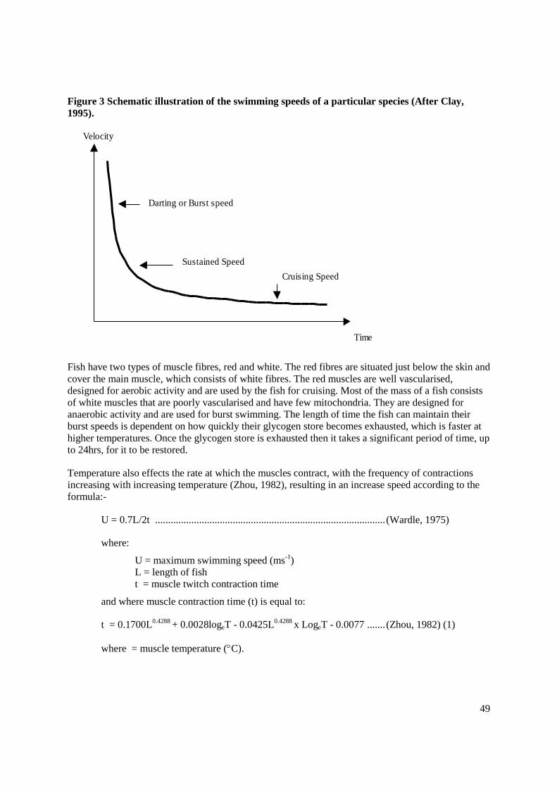
49
Figure 3 Schematic illustration of the swimming speeds of a particular species (After Clay,
1995).
Fish have two types of muscle fibres, red and white. The red fibres are situated just below the skin and
cover the main muscle, which consists of white fibres. The red muscles are well vascularised,
designed for aerobic activity and are used by the fish for cruising. Most of the mass of a fish consists
of white muscles that are poorly vascularised and have few mitochondria. They are designed for
anaerobic activity and are used for burst swimming. The length of time the fish can maintain their
burst speeds is dependent on how quickly their glycogen store becomes exhausted, which is faster at
higher temperatures. Once the glycogen store is exhausted then it takes a significant period of time, up
to 24hrs, for it to be restored.
Temperature also effects the rate at which the muscles contract, with the frequency of contractions
increasing with increasing temperature (Zhou, 1982), resulting in an increase speed according to the
formula:-
U = 0.7L/2t ......................................................................................... (Wardle, 1975)
where:
U = maximum swimming speed (ms-1
)
L = length of fish
t = muscle twitch contraction time
and where muscle contraction time (t) is equal to:
t = 0.1700L0.4288
+ 0.0028logeT - 0.0425L0.4288
x LogeT - 0.0077 ....... (Zhou, 1982) (1)
where = muscle temperature (C).
Velocity
Time
Cruising Speed
Sustained Speed
Darting or Burst speed

50
The length of time the fish can maintain their burst swimming speeds can be determined from the
equation:-
tm = E / (Pc-Pr) ..................................................................................... (Beach, 1984) (2)
where:
tm = endurance time (s)
Pc = Chemical power = 0.9751 x e-0.00522T
x U2.8
x L-1.15
(Zhou, 1982)
Pr = Power from oxygen uptake (W) = 4.44 x 10.836L2.964
E = Total energy store (J Kg-1
) = 2790 x 10.836L2.964
Using equations 1 and 2, Beach (1984) produced two sets of curves one relating maximum swimming
speed to fish length and temperature (Figure 4) and the other showing the length of time (i.e.
endurance) the maximum swimming speed could be maintained in relation to temperature and size
(Figure 5). These factors were combined by Larinier (1992b) to demonstrate the relationship between
swimming speed and endurance for different sizes of fish at different temperatures (Figure 6) . It has
been assumed in the construction of the graphs that all fish of the same size have the same swimming
capability.

51
Figure 4 Maximum swimming speed in relation to fish length and temperature (After Beach,
1984)
Figure 5 Endurance at maximum swimming speeds in relation to fish length and temperature
(After Beach, 1984)
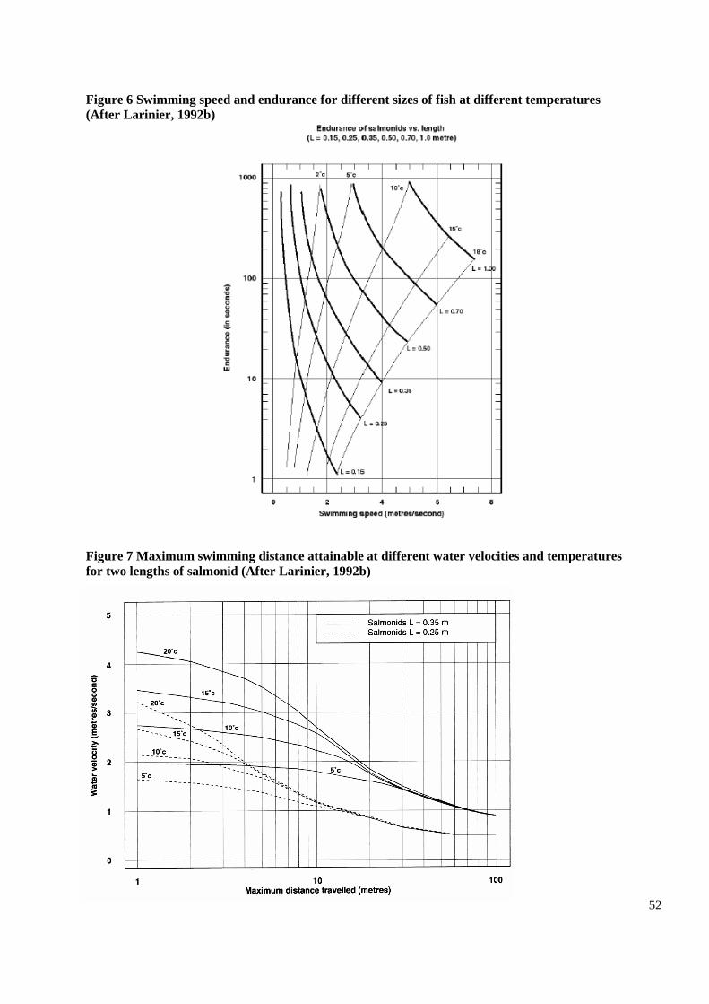
52
Figure 6 Swimming speed and endurance for different sizes of fish at different temperatures
(After Larinier, 1992b)
Figure 7 Maximum swimming distance attainable at different water velocities and temperatures
for two lengths of salmonid (After Larinier, 1992b)

53
The estimates of swimming performance, which were reported by Beach (1984) were determined
from tail-beat frequency and the physiological relationship with temperature but relates to maximum
swimming speed. These estimates are theoretical rather than empirical, but nevertheless the useful
relationships derived are widely used to provide the criteria for designing passes for migratory
salmonids, including salmon, sea trout and brown trout. Given the nature of the data it is sensible,
when considering the capacity of fish to manage the hydraulic conditions in any particular facility, to
allow a healthy margin of tolerance. Thus, in pool passes the traverse velocities should be well inside
the maximum swimming ability and preferably nearer burst speed, while the resting pool areas should
generally have velocities within the sustained or cruising capability of the fish. In passes where fish
have to swim a considerable distance, such as baffled type fishways, then the mean water velocities
should not usually be higher than the burst speed of the fish. Alternatively fish should be able to swim
a net distance some two to three times the length of the flight of pass proposed between resting areas.
Laboratory studies on burst and endurance swimming speeds for some UK species including barbel,
bream, brown trout, chub, dace, eel & elver, grayling, roach, smelt and twaite shad have been
completed in recent years (Clough & Turnpenny, 2001; Turnpenny, Blay, Carron & Clough, 2001;
Clough, Lee-Elliott, Turnpenny, Holden, & Hinks 2004a & b; Clough, Le-Elliott, Holden, &
Turnpenny, 2003; Clough, Le-Elliott, Holden, & Turnpenny, 2004; Clough, O’ Keefffe, & Holden,
2004; Watkins, Liney, & Turnpenny, 2007; and O’Keeffe & Clarke, 2008). Some typical results are
given in Table 2 below. Swimming speeds of eel are low particularly in relation to body length,
probably because these anguilliform shaped fish lack the caudal fin of carangiforms and therefore
cannot generate the same momentum.
Table 2 Examples of Swimming speeds for some UK fish of 15cms fork length at 10C and eel of
30cms at 15°C (SWIMIT version3_3 Nov 2006)
Species
Mean Burst Speed Median Sustained Speed 90%ile Sustained Speed
ms-1
bls-1
ms-1
bls-1
ms-1
bls-1
Roach 1.27 8.46 0.70 4.67 0.45 3.00
Dace 1.35 9.00 0.58 3.87 0.48 3.20
Chub 1.30 8.67 0.93 6.20 0.53 3.53
Trout 1.35 9.00 1.17 7.80 0.81 5.40
Eel 1.14 3.80 0.25 0.83 0.11 0.37

54
Data from these empirical studies have been used to generate models for the swimming performance
of these species, and these are presented in the program SWIMITversion3_3 Nov06. The program
estimates the burst swimming speed and endurance time as well as the sustained swimming speed (i.e.
that speed which can be maintained for >200min), dependent on fish size and temperature. The
program also allows the operator to select that proportion of the population that can maintain a certain
sustained speed. For example it is possible to estimate the speed that can be obtained by 50% of the
population (i.e. the median speed), or say 80 or 90% (i.e. percentiles) whatever is desired. This has
obvious benefits when looking at the implications of different designs, but essentially it facilitates an
approach that permits designs to be produced that we can be more confident will cater for the majority
of the population, rather than an average one. In addition it is also possible to calculate how long the
fish can maintain their burst swimming speed in relation to water velocity. For more information see
the series of Environment Agency R&D reports referenced above.
It must be recognised that while empirical data, the swim speeds have been compartmentalised in the
sense of creating discrete windows or periods of time in which any described speed can be sustained.
Clearly, actual performance of speed and endurance has a continuously inverse relationship. In
particular the Critical Burst Speed (CBB) methodology used for swimming speed trials in laboratory
conditions probably provides a conservative estimate of the actual ability of fish in the wild. For
example, migratory fish are often forced to swim at speeds that are greater than their maximum
sustained speed (defined as sutainable for 20 seconds), can volitionally sustain faster speeds for short
durations, and can change gait to maximise distance travelled against a particular water velocity
(Peake 1998, Castros-Santos 2005). Nevertheless, the swim speeds generated by SWIMIT for
example, provide robust guidelines for designing fish passage mitigation devices in most cases.
Preceding the work by Clough et al, 2003 there was very limited information about the swimming
ability and endurance of Alosa alosa and Alosa fallax. Litaudon (1985) estimated that the burst
swimming speed of Alosa alosa ranged from 3.1 ms-1 to 4.7 ms-1 at temperatures of 16 to 17°C. At
these temperatures the fish could maintain such speed for approximately 6.5s. The maximum speed
was estimated at between 4.1 ms-1 and 6.1ms-1, but could only be sustained for a few seconds. Table
3 summarises the swimming capabilities of shad measuring 0.30 to 0.50 m in length (Larinier, 1996),
and Table 4 gives some examples of swimming capability of Alosa fallax from SWIMIT
version3_3Nov06.
Table 3 Swimming capabilities of shad (0.30 to 0.50 m in length) from Larinier (1996).
Temperature
(oC)
Maximum speed (ms-1
) Endurance at maximum speed
(sec)
Cruising speed (ms-1
)
10 2.75 – 3.30 15 – 60
0.8 – 1.5 15 3.50 – 4.30 10 – 25
20 4.40 – 5.40 5 – 10
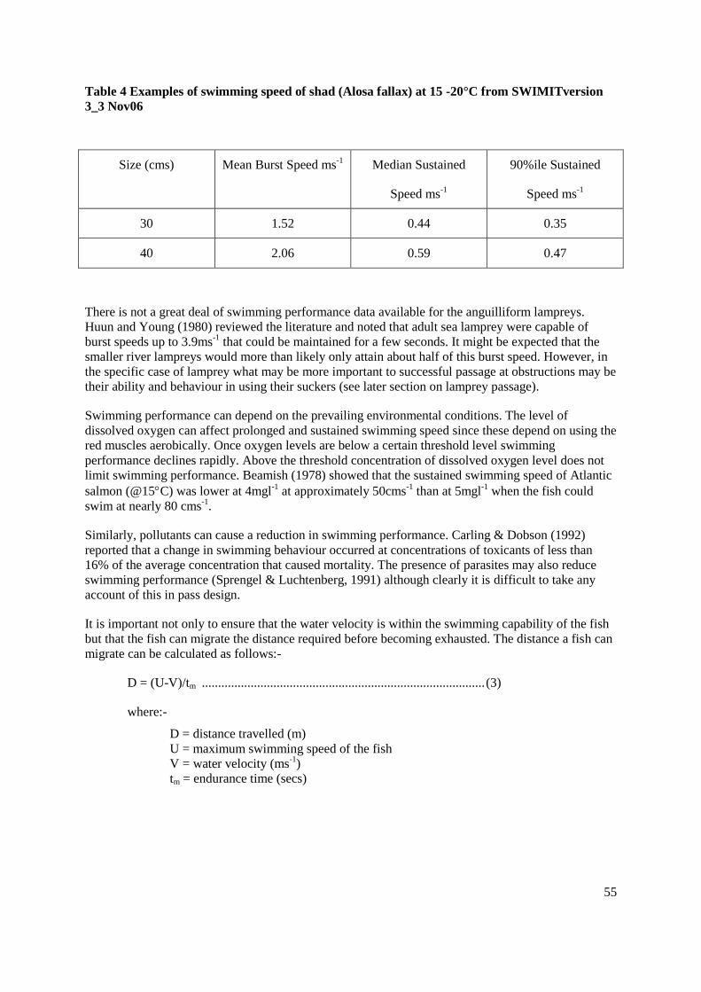
55
Table 4 Examples of swimming speed of shad (Alosa fallax) at 15 -20°C from SWIMITversion
3_3 Nov06
Size (cms) Mean Burst Speed ms-1
Median Sustained
Speed ms-1
90%ile Sustained
Speed ms-1
30 1.52 0.44 0.35
40 2.06 0.59 0.47
There is not a great deal of swimming performance data available for the anguilliform lampreys.
Huun and Young (1980) reviewed the literature and noted that adult sea lamprey were capable of
burst speeds up to 3.9ms-1
that could be maintained for a few seconds. It might be expected that the
smaller river lampreys would more than likely only attain about half of this burst speed. However, in
the specific case of lamprey what may be more important to successful passage at obstructions may be
their ability and behaviour in using their suckers (see later section on lamprey passage).
Swimming performance can depend on the prevailing environmental conditions. The level of
dissolved oxygen can affect prolonged and sustained swimming speed since these depend on using the
red muscles aerobically. Once oxygen levels are below a certain threshold level swimming
performance declines rapidly. Above the threshold concentration of dissolved oxygen level does not
limit swimming performance. Beamish (1978) showed that the sustained swimming speed of Atlantic
salmon (@15C) was lower at 4mgl-1
at approximately 50cms-1
than at 5mgl-1
when the fish could
swim at nearly 80 cms-1
.
Similarly, pollutants can cause a reduction in swimming performance. Carling & Dobson (1992)
reported that a change in swimming behaviour occurred at concentrations of toxicants of less than
16% of the average concentration that caused mortality. The presence of parasites may also reduce
swimming performance (Sprengel & Luchtenberg, 1991) although clearly it is difficult to take any
account of this in pass design.
It is important not only to ensure that the water velocity is within the swimming capability of the fish
but that the fish can migrate the distance required before becoming exhausted. The distance a fish can
migrate can be calculated as follows:-
D = (U-V)/tm ....................................................................................... (3)
where:-
D = distance travelled (m)
U = maximum swimming speed of the fish
V = water velocity (ms-1
)
tm = endurance time (secs)

56
As swimming performance is dependent on temperature such estimates need to be made for the range
of temperatures the migrating fish might experience. Examples of the distances that might be covered
by relatively small salmonids of two different size is shown in Figure 7 (After Larinier, 1992b).
Some Simple Swimming Speed Criteria for Fish Passes
While more detailed consideration can be given to specific species and sizes of fish using the various
sources outlined above to match to the individual site, some general guidelines can be provided. Table
4 below gives some guidelines for maximum water velocities and head drops in pool passes, and
mean water velocities and maximum flight lengths in baffle fishways.
Table 4 Some simple guidelines for basic parameters of pool, and baffle, fish passes
Pass Parameters
SPECIES
Coarse fish Brown trout Sea trout Salmon
POOL
PASS
Max
Vel
(ms-1
)
1.4-2.0 1.7-2.4 2.4-3.0 3.0-3.4
Head
drop
(m)
0.1-0.2 0.15-0.3 0.3-0.45 0.45-0.6*
BAFFLED PASS
Mean
Vel
( ms-1
)
1.1-1.3 1.2-1.6 1.3-2.0 1.3-2.0
Length
(m) 8-10 8-10 10-12 10-12
*It would only be in exceptional circumstances that a head drop of >0.45m would be used, for
example for a pre-barrage or else a single jump amongst many others.
Location and Attraction
There are many different types of fishway which are known to provide hydraulic conditions that fish
can pass through readily. Several of these are outlined in this manual. However, in many respects the

57
most significant problem in passing fish, either upstream or downstream, is that of attracting the fish
into the fish pass facility. For species such as migratory salmonids where it is necessary to provide
passage for all fish waiting to move upstream (which can be the whole or a significant part of the
migrating population) this is clearly an onerous requirement. For species such as coarse fish it may be
acceptable for only a proportion of fish to move upstream and location and attraction is less critical.
The reader is directed to the excellent description of the factors applying to the location and
attractivity of fish passes is given by Larinier, 2002 in Chapter 4 of the BFPP supplement on
Fishways. This concisey examines factore influencing choice of location of fishawys and the
hydraulic coditions required at the fish pass entrance(s).
Choice of Location at an Obstruction
Fishways should be located where migrating fish are observed either to congregate, or else attempt to
pass, when actively trying to move upstream. The observation may be direct visual means or else by
means of a monitoring study employing, for example, radio-tracking or acoustic tracking techniques.
The value of such information cannot be over-stated and every effort should be made to collect it
before committing to pass design. This should be possible where a migratory population is present but
is clearly not possible when one is not, eg. in a river subject to a restoration programme, or when a
new obstruction is being constructed. In the latter case the experience of the fishway designer has to
be relied upon.
The general principle i.e. best practice should be to locate the entrance to the fishway at the most
upstream point which migrators can reach at an obstruction since this is where they will tend to move
too. The topography of a pool might suggest where holding areas or approach locations may be. In
some cases the topography might be altered by using rip-rap etc to create shallower areas that deflect
approaching fish into correspondingly deeper areas that lead them to the fish pass entrance(s).
A location near one or other banks should be favoured since this is where many species tend to
migrate and especially salmonids and shad. Generally location at the bank also facilitates monitoring
and maintenance of the facility. In some cases, particularly on large watercourses consideration may
need to be given to installing facilities on both banks. Mid-river locations should be avoided unless
this is clearly where fish move to, are led to or attracted by existing configurations which cannot
easily be changed. Siting of a pass where significant active aggregation of alluvial material is taking
place, often on the inside of bends, should generally be avoided.
It is recommended that the entrance to the fishway is not located more than 2m downstream of the
edge of the barrier unless conditions are such that entrance to the facility is masked by other hydraulic
conditions e.g. significant turbulence, standing wave. If the entrance is located too far downstream,
and especially if it is without sufficient attraction, then fish are unlikely to find it since they will tend
pass the entrance and congregate immediately below the obstruction. These fish will be reluctant to
search downstream for an alternative route. In these circumstances the very least that will occour is
that fish will be delayed, and it will almost certainly reduce the passage rate efficiency of the facility.
If the entrance has to be well downstream of the obstruction because of site constraints, then this
should be compensated for, by increasing the attraction flow significantly.
In the case of low-head hydropower developments the associated fish pass(es) should have entrances
that are co-located and co-terminus with the turbine discharge, and preferably the pass jet will
discharge parallel to that from the turbine outflow.

58
The upstream exit of a pass should not be located where there is a danger of fish being immediately
swept back downstream.
If the river bed downstream can be modified to lead fish to the entrance of the pass, or else control
structures can be managed to lead fish, then this should be taken account of in deciding the fishway
location.
Flow Conditions at the Entrance
The jet of water issuing from a fishway must be discernible to the fish amongst all the other
competing flows and from as far away as possible. Attractivity will depend on the direction and the
momentum (discharge x velocity) of the pass entrance jet. The greater the momentum of the jet the
further the entrance jet penetrates the tailwater and the more attractive is the fish pass (Larinier, 2002
c). Exit velocity must be in excess of 1ms-1
for all species and preferably be of the order of 2-2.4ms-1
for large salmonids (corresponding to head drops of 0.2 – 0.3m). In order to maintain a high velocity
the occurrence of hydraulic jumps must be avoided since this will dissipate the energy. Where a pass
entrance is located competing with the flow from low-head hydro turbines the velocity of the pass jet
should be at least twice that of the turbine outflow.
Care should be taken to avoiding the attraction jet from a fishway being masked by cross-flows or by
injecting it into an area of high turbulence. Every effort should be made to align the jet issuing from
the fishway with the other local velocity lines. It is also good practice to avoid a situation where the
issuing jet is not in the vicinity of a re-circulation eddy where fish may take up orientations which do
not facilitate their finding the entrance.
Given a choice in the construction of a new structure, or refurbishment of an old one, it is better to
have overshot water-control structures adjacent to the fishway rather than under-shot ones. Radial
gates or double-leaf sluice gates that drop a little to permit fine control are far better than bottom-only
opening gates. This is because the high velocity jets that issue from such structures at low to medium
river discharges is both highly attractive to fish, and impassable. They thus draw fish away from the
fishway, to areas where they have no hope of passing. While there will be a limit to the period of the
river hydrograph over which over-shot conditions can be maintained, it is likely that it will include the
whole or the greater part of the migration window of flow. The overshot condition can attract fish
because of the noise it generates but the velocity away from the structure is low and does not compete
unduly with the exit jet from the fishway.
Discharge from the Fishway
Deciding upon the discharge through a fishway is not an easy or clear-cut decision. Clearly a major
part of the attraction to the facility is the volume of flow and the larger the proportion of flow in the
fishway compared to that in the watercourse, the better. Where fish passes are not positioned
optimally then much greater discharges may be required to compensate and maintain pass efficiency.
The problem of deciding just how much flow is exacerbated on large watercourses of tens m3s
-1
because of the increasing size and cost of the facilities involved.
French guidelines for larger (100 m3s
-1) watercourses are for the fishway to take between 1-5% of
the competing flow at the obstruction, during the migration period (Larinier, 1992c). On some of the
large French rivers such as the Garonne and Dordogne with discharges of several hundred cumecs,
attraction flows are taken of about 10% of minimum flow, equating to around 1 – 1.5% of highest
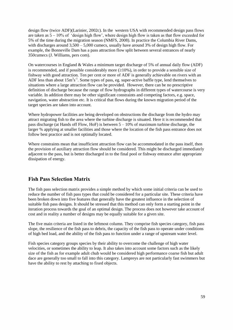
59
design flow (twice ADF)(Larinier, 2002c). In the western USA with recommended design pass flows
are taken as 5 – 10% of ‘design high flow’, where design high flow is taken as that flow exceeded for
5% of the time during the migration season (NMFS, 2008). In practice the Columbia River Dams,
with discharges around 3,500 – 5,000 cumecs, usually have around 3% of design high flow. For
example, the Bonneville Dam has a pass attraction flow split between several entrances of nearly
350cumecs (J. Williams, pers com).
On watercourses in England & Wales a minimum target discharge of 5% of annual daily flow (ADF)
is recommended, and if possible considerably more (10%), in order to provide a sensible size of
fishway with good attraction. Ten per cent or more of ADF is generally achievable on rivers with an
ADF less than about 15m3s
-1. Some types of pass, eg. super-active baffle type, lend themselves to
situations where a large attraction flow can be provided. However, there can be no prescriptive
definition of discharge because the range of flow hydrographs in different types of watercourse is very
variable. In addition there may be other significant constraints and competing factors, e.g. space,
navigation, water abstraction etc. It is critical that flows during the known migration period of the
target species are taken into account.
Where hydropower facilities are being developed on obstructions the discharge from the hydro may
attract migrating fish to the area where the turbine discharge is situated. Here it is recommended that
pass discharge (at Hands off Flow, HoF) is between 5 – 10% of maximum turbine discharge, the
larger % applying at smaller facilities and those where the location of the fish pass entrance does not
follow best practice and is not optimally located.
Where constraints mean that insufficient attraction flow can be accommodated in the pass itself, then
the provision of auxiliary attraction flow should be considered. This might be discharged immediately
adjacent to the pass, but is better discharged in to the final pool or fishway entrance after appropriate
dissipation of energy.
Fish Pass Selection Matrix
The fish pass selection matrix provides a simple method by which some initial criteria can be used to
reduce the number of fish pass types that could be considered for a particular site. These criteria have
been broken down into five features that generally have the greatest influence in the selection of
suitable fish pass designs. It should be stressed that this method can only form a starting point in the
iteration process towards the goal of an optimal design. The process does not however take account of
cost and in reality a number of designs may be equally suitable for a given site.
The five main criteria are listed in the leftmost column. They comprise fish species category, fish pass
slope, the resilience of the fish pass to debris, the capacity of the fish pass to operate under conditions
of high bed load, and the ability of the fish pass to function under a range of upstream water level.
Fish species category groups species by their ability to overcome the challenge of high water
velocities, or sometimes the ability to leap. It also takes into account some factors such as the likely
size of the fish as for example adult chub would be considered high performance coarse fish but adult
dace are generally too small to fall into this category. Lampreys are not particularly fast swimmers but
have the ability to rest by attaching to fixed objects.

60
The slope of the structure is important for two reasons. The first is that some pass designs will only
operate over a small range of slopes. The second is that most fish pass projects are spatially confined
in some way, and this often precludes the use of some types of pass.
Many rivers carry substantial amounts of debris due to the nature of the catchment and the hydrology
of the catchment. In some catchments the proximity of a supermarket is as important as the area
covered by forest in terms of the amount of debris the fish pass is challenged by. Some fish passes are
much more resilient to debris than others.
For some rivers the resilience to bed load movements could be a major factor influencing the final
design. For example, some pool and traverse passes have been known to fill up with gravel where
they have been built on rivers with a high bed-load movement. In contrast, side baffle Denil fish
passes do not have bottom baffles, and therefore do not accumulate bed material.
Under many circumstances the range in upstream water level limits the choice of fish pass. The super
active baffled pass is an excellent fish pass in many respects but is limited in the range of upstream
water levels that can be accommodated before the pass is drowned. In contrast, the side baffle Denil
pass requires fish of relatively high swimming performance but can accommodate a large range in
upstream water level whilst remaining operative.
A simple procedure is included below in a selection matrix.

61
Fish Pass Selection Matrix
Pool Fishways Baffled Fishways Notes
Requirement Po
ol
& T
ra
ve
rse
(plu
ng
ing
)
Po
ol
& T
ra
ve
rse
(st
rea
min
g)
Verti
ca
l (p
ool
&)
Slo
t
Po
ol
& O
rif
ice
V'
No
tch W
eir
s
Ice
Ha
rbo
r
Po
ol
& C
hute
Preli
min
ar
y W
eir
s
Fis
h L
oc
ks
Fis
h L
ifts
Pla
in B
aff
le D
en
il
Fa
tou
Denil
Ala
ska
n '
A'
Denil
Super
Acti
ve B
aff
le (
La
rin
ier)
Chev
ro
n B
aff
le
Sid
e B
aff
le F
ishw
ay
Species Salmonid sp. Y Y Y Y Y Y Y Y Y Y Y Y Y Y Y Y ND= NO DATA AVAILABLE
Hi perf coarse sp. Y Y Y Y Y ND ND Y Y Y Y ND Y Y n n
Lo perf coarse sp. n Y Y n Y ND ND Y Y n n ND n Y n n
Alosa sp. n Y Y n Y Y ND Y Y n n ND n Y n n
Eel sp. n n Y n n n ND Y Y n n ND n n n n
Slope <5% Y Y Y Y Y Y Y Y Y Y Y Y Y Y Y Y Excludes resting pools in the case of baffled fishways
>5%<10% Y Y Y Y n Y Y Y Y Y Y Y Y Y Y Y
>10%<20% n n Y n n n n n Y Y Y Y Y Y Y Y
>20%<25% n n n n n n n n n Y Y n Y n n Y
>25% n n n n n n n n n Y n n n n n n
Debris resilience High n n n n Y n n Y Y n n n n Y Y n Relates to basic properties of the pass type
Bed Load Capacity High n n n n n n n Y n n n n n n n Y Some passes can clog with gravel etc.
Range in upstream head capacity Large n n Y n n n n Y n Y n n n n n Y
Total
Operation of fish pass selection matrix
Step
A Photocopy the matrix sheet
B On the copy use a highlighter pen to select the important rows for the desired installation
EG. High light the Salmonid and Alosa sp. rows along with the range in upst. head capacity
C For each fish pass column add all of the highlighted cells with a Y in them and place the numerical result in the Total row for that column
D The highest scoring fish passes should be good options with which to start actual calculations for the site

62
FISH PASS TYPES
There are many different types of fish pass, which are generally variations on the themes of steps,
slopes or lifts. The `step` approach involves splitting the height to be passed into a series of small
drops with various forms of traverse separating resting pools. The `slope` approach involves spilling
water down relatively steep slopes where various forms of baffles are used to dissipate energy and
slow down the water velocity. Lifts involve attracting fish into confined spaces and then lifting them
either mechanically or hydraulically and depositing them upstream.
To these can be added diversion or by-pass channels that may vary from the totally artificial to the
`natural stream-mimicking` type, and many forms of `easement`.
In England and Wales the vast majority of fish passes are installed in `low-head` situations and this
has tended to limit the type of passes considered. In recent years the range of passes being used has
begun to expand. For completeness most types are covered in this section, although some are rarely if
ever used.
Pool Passes
General
Pool passes are perhaps the oldest type of pass in use. They are generally applicable for most fish
species, are extensively used throughout the world and in most cases require low maintenance. They
can frequently change direction, even very sharply, and therefore may be integrated into some
locations much more easily than some other types of pass.
Pool and traverse fish passes largely fall into two categories distinguished by the type of flow between
pools (Figure 8). When the lower pool water level is substantially above the level of the notch
between the pools (i.e. H2 0.5-0.6H1) then the pool pass is of the `streaming flow` type (Larinier,
1992). Energy is dissipated by large re-circulation eddies in the downstream pool. When the lower
pool water level is below, or not far above the level of the notch between the pools, then the energy is
dissipated by turbulent mixing and a hydraulic jump at the bottom of the fall. This type of pass is of
the `plunging flow` type. The transition between plunging and streaming flow is associated with
instability and hysteresis. In pool passes with notches the notch flow, particularly at the downstream
entrance, may in some cases become streaming while the flow over the adjacent overfall may remain
plunging.

63
Figure 8 Plunging and streaming flow passes (After Larinier, 1992a).

64
The connection between the pools may take one of several forms including simple over-falls, a variety
of notches, vertical slots, or orifices. There may also be a combination of these. Pool & traverse or
Pool & Weir passes are not suitable for benthic species such as barbel, which will require a Vertical
Slot or Orifice pass i.e. with openings extending to the bottom of the cross-walls, to be effective.
The following guidelines are generally adopted for the head loss between the pools, for the size of the
traverses, slots and orifices, and for the power density in each pool. These apply to all the major types
of pool pass detailed below.
A maximum head loss of 0.3-0.45m for migratory salmonids and non-migratory trout, 0.20-0.30m for
the more powerful swimming coarse fish (Chub) and shad, and 0.10-0.20m for other cyprinids and
piscivorous fish. Maximum head drop between pools will generally occur at the minimum design flow
in the pass, corresponding with the minimum river discharge for which the pass is designed to be
operational.
The maximum water velocity occurring in the drop between the pools, which the fish have to `burst`
or jump through approximates to:
V = (2g DH) 0.5
ms-1
As a guide this gives the following velocities:
Head Drop (m) Velocity (ms-1
)
0.10 1.4
0.15 1.7
0.20 2.0
0.25 2.2
0.30 2.4
0.45 3.0
0.60 3.4

65
When considering the design of pool passes and the distribution of head drops it is often sensible to
put a maximum head drop at the fish pass entrance at lower flows, and to distribute smaller head
drops in the remaining pools. This is because tail-water levels often rise more rapidly than head-water
levels, which results in reduce head drops, water velocity, and therefore attraction at the pass entrance
on rising fows. If it facilitates smaller head drops in the remainder of the structure it will also help
constrain power densities in the pools, resulting in easir passage and an extension of the operational
window for the pass.
The traverses (notches, slots etc) in `streaming flow` passes must be at least 0.30-0.40m wide for large
migratory salmonids, 0.45m for shad, 0.20m for trout and 0.15m for small coarse fish. In `plunging`
flow passes they should be wider and a minimum of 0.6m is usually taken for large migratory
salmonids and 0.3m for trout and coarse fish.
The traverses should usually be a minimum of 300mm thick, with well-rounded nappes in order to
ensure that flow adheres to its surface. An adherent nappe is important since flow breaking away from
the traverse and creating an air gap is not conducive to the passage of fish, and especially the smaller
individuals. Fish are forced to jump and this means that they can easily be dis-orientated. This is a
particularly important consideration in plunging flow type passes. Thinner walls, with chamfered or
specially angled shapes may be employed in vertical slot type passes.
Power densities (strictly power dissipation per unit volume) up to 150-200Wm-3
are suitable for
migratory salmonids dependent on the number of pools and the discharge in the pass. Maximum
values at the lower end of this range should be used as the number of the pools increases, and for
smaller passes with modest discharge (<1.0m3s
-1). Power densities of up to 100-150Wm
-3 are suitable
for trout, shad, and coarse fish species, but maximum values at the lower end of this range are
recommended, especially for coarse fish. These recommended maximum power densities should be
achieved for the smallest pool at the highest discharge for which the pass is designed to operate
(usually at Q10 river discharge). Pools at sharp turns i.e. approaching 180° in a fishway should
normally have significantly lower power density values e.g. 100Wm3 for large migratory salmonids
Power density is a measure used to describe the turbulence in a volume of water. It is the potential
energy per unit time spread throughout a known volume of water in a pool. The potential energy
entering a pool per second may be calculated using the following formula:
PE = Q . p . g . DH
Where:
PE = the potential energy entering the pool per second
Q = the water flow in the fish pass (m3s
-1)
p = the density of water (1000kgm-3
)
g = acceleration due to gravity (9.81 ms-1
)
DH = the drop between pools (m)
This has units of energy per unit time, in this instance Joules per second or Watts, a unit of power. To
calculate the power dissipation or density value this figure is divided by the volume of the receiving
pool, i.e. the volume of water throughout which the input power is spread or dissipated:

66
Pv = PE
V
where
Pv = the power dissipation per unit volume or power density [Wm-3
]
V = the volume of the receiving pool [m3]
Put more simply:
Pv (Wm-3
) = 9810 x Q x DH
L x W x Dm
where
L = length of pool (m)
W = width of pool (m)
Dm = mean depth of pool (m)
Pool dimensions for these estimates are applied using the precautionary principle. Guidelines for
length of pool are 7-12 times the head loss between pools (width of slot in slot fishways, diameter of
orifice in orifice fishways). The minimum length can be taken as three times the length of the largest
fish expected to pass. In the case of large migratory salmonids a minimum length of pool
recommended is 3m. Guidelines for width of pool are set by the length and power density constraints
but a normal minimum for large migratory salmonids is 2m. The minimum depth must be at least
twice, and preferably three times, the head drop in plunging flow passes. A minimum depth of 1.2m is
generally used for large migratory salmonids. For trout and coarse fish the pool sizes may be reduced
subject to satisfactory power densities being present, however lengths and widths less than 1.8m &
1.2m respectively and depths less than 0.6m would not normally be satisfactory.
It should be borne in mind that a failure to dissipate power satisfactorily would lead to the transfer of
residual power to the next pool, thus creating a tendency for conditions in subsequent pools to worsen
incrementally.
A problem that can occasionally occur in long pool passes is a phenomenon known as surge or seiche.
An oscillating transverse wave or clapotis is formed that can reach a height of several feet. It was
observed in a long fishway at the McNary Dam on the Columbia River, USA, where after a series of
tests it was resolved by bevelling the tops of the weirs (Clay, 1995). Clay also describes how a better
solution for preventing oscillation waves was found by laboratory testing using a combination of
bevelled crests at each side of a higher centre section, and short wing or stub-walls projecting
upstream. This is the Ice Harbor type of pool pass described later in this section. This phenomenon
has been observed in several other locations (Larinier, pers comm), including a long pool pass – the
Deep Navigation Cascade- on the R. Taff-Bargoed in South Wales. In the latter case a solution for this

67
problem, which occurs at low to medium flows, has yet to be developed but is expected to include the
provision of stub-walls in some of the pools.
Pool & Weir or Pool & Traverse
In Britain pool and traverse passes have typically been based on the plunging type form shown in
Figure 9, which gives the minimum recommended dimensions for a pass for large migratory
salmonids, i.e. salmon & most sea trout (Anon, 1942). In the case of populations of smaller sea trout,
or non-migratory salmonids and coarse fish, there is some potential for reducing these minimum
dimensions a little. Of course, passes may also be very substantially bigger.
The notches are effectively designed to provide effective communication and passage between pools
at low flows. However, they may also serve to constrain flows as river discharge rises if the cross-
wall(s) beside it are increased in height i.e. forming a tall notch, so that as river discharge rises flow in
the pass is constrained by what can pass the notch width only. When head is allowed to rise on the
cross-walls as well, then the total pass discharge rises very quickly and power densities soon exceed
the guidelines.
Suitable Species: Plunging flow passes, requiring fish to swim in the nappe formed from pool to pool
are more suited to salmonids, but can be used by coarse fish (except the more benthic
species)provided that the head difference and energy densities are limited. Streaming flow pool passes
are essential for shad, and generally more suitable for coarse fish. Pool & Weir or Pool & Traverse
passes are not particularly suitable for eel or lamprey though they may be adapted to be partly
effective (see relevant sections on eel & lamprey).
Head difference: A maximum head loss of 0.3-0.45m for migratory salmonids, 0.20-0.30m for brown
trout and the more powerful swimming coarse fish (e.g chub,) and shad, and 0.10-0.25m for other
cyprinids and piscivorous fish.
Length & Width of pools: Minimum length and width of pools is 3m & 2m respectively for large
migratory salmonids. Minimum length is 3 x length of largest fish requiring passage for other species.
Minimum width is 3 x notch width. Notch widths and depths are not generally <0.6m x 0.25m for
large migratory salmonids, 0.3m x 0.25m for other species. However, the depth of the notch might be
reduced to say 0.2m where head drops are 0.45m, e.g. 0.3m drop.
Gradient: Should not exceed 10% but may be further influenced by the pool dimension and power
density guidelines above.
Flow: The flow in the minimum sized pass for large migratory salmonids, illustrated in Figure 9, is
0.13m3s
-1. It may vary substantially. Pass discharge (m
3s
-1) in this contracted notch is best estimated
using the Francis equation (Beach, 1984) Q = 1.84. [b - 0.2h]. h1.5
. For the rounded traverse Q = 1.85.
b. h1.5
. A more generalised diagram of a Pool & Traverse pass and an equation for estimating flow is
also given in Figure 8 (After Larinier, 1992a). The coefficient Cd is determined mainly by the
thickness of the wall and the profile of the notch. Cd may vary from 0.33 for a sharp broad-crested
weir type to 0.50 for a profile shaped to achieve an adherent nappe (ogee profile). Usually it is near to
0.40.
Velocity: 1.4 to 3.0 ms-1
Strengths: Extensively tried and tested, applicable to many species, low maintenance requirements.

68
Weaknesses: The overall slope of this type of pass is generally low at 10-12.5%, thus costs are
generally high. Generally an inability to cope with large increases in upstream head because total flow
and thus energy transfer becomes very large very quickly. Can be prone to debris blockage &
sedimentation where there is movement of large material such as cobble. Not suitable for the more
benthic coarse fish species such as barbel.
Figure 9 Schematic diagram of a typical Pool & Traverse fish pass with notched traverse and
plunging type flow. Dimensions given are the recommended minima for large migratory
salmonids (After Beach, 1984 & Larinier 1992a).
Generalised geometric characteristics and discharge equation for a pool and
traverse pass (downstream pool level lower than invert of the notch)
(After Larinier, 1992a)

69
Vertical Slot
Vertical slot fish passes (Figure 10) consist of a rectangular channel with a sloping floor. Pools are
formed by partitions between the pool with either one or two vertical slots. A water jet is formed at
each slot and the energy dissipated in the pool below. Normally a projection is incorporated on the
upstream edge of the slot, which is considered important to maintain a stable flow through the slot. If
the flow becomes unstable fish may become disoriented.
A number of different configurations for single slot passes (Nos 1-7, Figure 12) were model-tested by
Rajaratnam, Van der Vinne & Katopodis (1986) and they commended the designs 1 & 2 (same
configuration but with or without a sill). Later, Rajaratnam, Katopodis & Solanki (1992) carried out
further tests and recommended three designs (Nos 6, 16 & 18, ), for practical use that had good
overall performance, and the virtue of simplicity of design and construction when compared to the
earlier configurations. Descriptions of other tried and tested configurations may also be found in R&D
Note 110 and Larinier (1992a).
In single slot passes a small sill of approximately 0.2-0.3m has often been included at the bottom of
the slot to stabilise and direct the water jet issuing into the pool where its energy is dissipated, and
also to limit the flow in the fish pass. This is because single slot passes are not as effective as
dissipating energy as paired slot passes, and because otherwise there is a tendency for the flow to
direct itself directly from slot to slot down the pass, effectively by-passing the pool. It is particularly
important to include the sill if the pools are <1.7m deep, or if the head drops are more than the usual
0.3m. On the other hand, there are advantages for the slot to be full depth with substrates used on the
bed to ensure roughness and good connectivity for the more benthic and the smaller fish species, and
also for invertebrates. This latter approach is much more likely where passage is being considered for
a wide variety of species including potamodromous ones
Vertical slot passes can be considered to be ubiquitous and cater for a wide variety of species and
sizes of fish, offering the full range of depth for passage, and are capable of functioning effectively
across a wide range of water levels.
The Fitzroy River fishway in Queensland, NE Australia was adapted to pass a wide range of non-
salmonid fish species, some as small as 40-120mm, by reducing the slot width to 0.15m, and the head
difference between pools to 0.10m (Stuart & Mallen-Cooper, 1999). Slot velocities were around
1.4ms-1
and pool energy dissipation values around 40W/m3. Pools were 1.95m long x 1.83m wide x
1.3m deep. The pass slope was 5%.
Manipulation of the dimensioning and hydraulic characteristics particularly in terms of energy
dissipation can modify the performance of these passes (Tarrade, Texier, David, & Larinier, 2008).
Modifying the length to width ratios of vertical slot passes and introducing energy dissipating devices
near the slots helped improve energy dissipation and reduce re-circulation eddies, both of which
features tend to limit the use of passes by small fiss.
On the Murray River several vertical slot passes have been constructed at 3 – 5% slopes that pass
small fish, but at 5% slopes are not effective for fish <100mm, which excludes several species that do
not grow that big. Recently trials have been conducted to increase the range and size of species using
such passes by increasing bed and wall roughness, introducing middle sills that partially block the
vertical slot, and reducing head drops at the entrance (Mallen-Cooper, Zampatti, Stuart &
Baumgartner, 2008). The wall roughness consisietd a secondary wall at a twenty degree angle to the

70
side-wall, consisting an array of 30cm perforated pipes set at a forty five degree angle in a frame. The
reduced turbulence resulting from these measures permitted much smaller fish down to 25mm to pass,
and increased passage rates by up to four times with wall roughness and six to thirteen times for
middle sills. However, the method was selective with some species still not able to pass.
It should be borne in mind that adapting such a pass for less able swimmers, or to cater for small fish,
by reducing head drops between pools can have a significant effect on attraction velocity at the
downstream entrance – perhaps greatly reducing attraction for migratory salmonids for example.
In some cases the bottom of slots has been adapted for species such as lamprey by providing brushes
on the sill (Laine, Kamula & Hooli, 1998). More recent evidence has shown that adapting slots, by for
example making them rounded rather than having sharp edges, can improve lamprey passage
characteristics because lampreys can use their suckers to aid passage (Moser, pers com).

71
Figure 10 Single and paired vertical slot passes (after Larinier, 1992a)
Generalised geometric characteristics and discharge equation
for a vertical slot pass (After Larinier, 1992a)
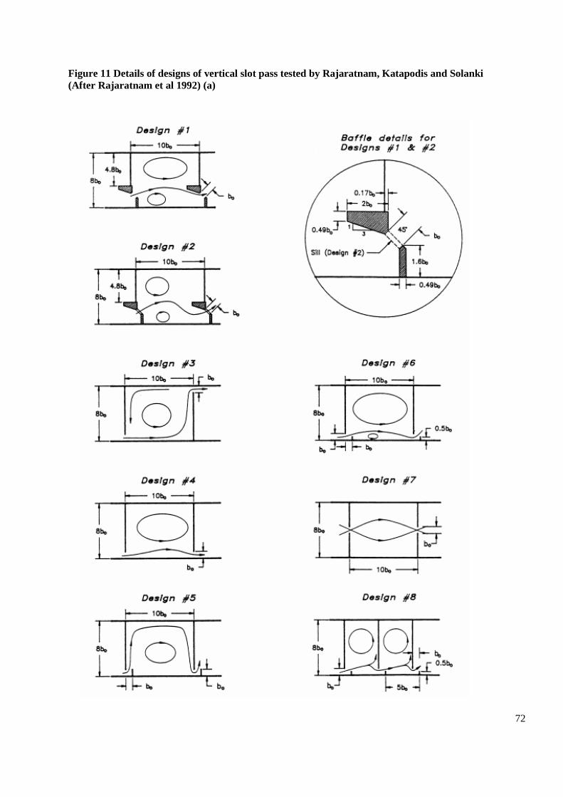
72
Figure 11 Details of designs of vertical slot pass tested by Rajaratnam, Katapodis and Solanki
(After Rajaratnam et al 1992) (a)
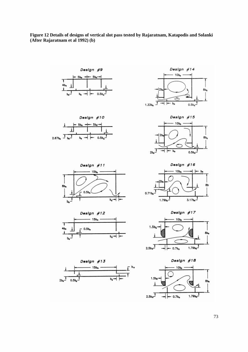
73
Figure 12 Details of designs of vertical slot pass tested by Rajaratnam, Katapodis and Solanki
(After Rajaratnam et al 1992) (b)

74
Suitable Species: Most fish species. Shad require specific additional features relating to their
preference for migrating as a shoal (sufficiently wide slot) and a need for visual cues (pass must be
lit).
Head difference: Approximately 0.3m for large salmonids, <0.2m for coarse fish
Length & Width of pools: Usually 10 and 8 times the slot width respectively. Slot width generally
from 0.2-0.6m, but can be less for non-salmonid species (Larinier, 1992). Minimum must be 0.2m for
trout, 0.3m for migratory salmonids, and 0.45m for shad.
Flow: Not generally suitable for large migratory salmonids unless discharge ≥0.7 m3s
-1, but may be
used for other species using lesser flows.
Discharge (m3/sec): An approximation of discharge is given by Q = 3.32. b. H1. h
0.5. Where H1 is the
depth of water on the upstream side of the slot (Andrew, 1991). More exact flows for any design may
be found in original references (e.g. Rajaratnam et al, 1992; Larinier, 1992; FAO/DVWK, 2002).
Generalised geometric and hydraulic parameters for determining flow are given in Figure 10 (After
Larinier 1992a). The shape and form of the slot affect the discharge coefficient, which may vary from
0.65 (slot sharply bevelled) to 0.85 (slot rounded).
Gradient: Usually 10%, but have been built at slopes between 5-12.5%.
Velocities: 1.4-2.4 ms-1
Strengths: Capable of accommodating large changes in upstream water level provided that the
downstream level varies in a similar manner. Provides a large range of water depth within the slot at
which fish may choose to pass from one pool to another. Can cope with large bed load. Suitable for a
wide range of fish species and fish sizes, especially with full depth notch(es) and bed roughening
material utilised to create lower velocity boundary and refuge areas. With bed roughening may also
pass some invertebrates.
Weaknesses: The overall slope of this type of pass is generally low at 5-12.5% thus costs are
generally high. Can be prone to debris blockage. Shad can become trapped or exhibit fall-back
behaviour if dead or re-circulation zones are excessive.
Pool & Orifice
Pool and orifice passes (Figure 13) comprise a series of pools formed by partitions in a rectangular
sloping channel. Water flows from pool to pool through submerged orifices. Discharge and velocity is
relatively stable compared to a weir type pass (discharge varies in proportion to square root of the
head as opposed to weir where it varies in proportion to 1.5 power of head).
Fishways consisting wholly pool & orifice units are rare, although some classic examples exist, e.g.
Pitlochry Dam Fishway (orifice 0.84m diameter, 0.45m head drop, pass discharge 1.4 m3s
-1), and a
very specific small orifice pass that has found use in Holland (Boiten & Dommerholt, 2005) for
passing coarse fish (discharge only 0.05-0.15 m3s
-1, orifice 0.2m wide x 0.3-0.6m high, head drop
0.05m) . Most often they are found as control sections at the head of other types of pass, because a
considerable increase in head pond level affects discharge in an orifice section very little. If all
orifices are the same size throughout a fishway then the head differences will even themselves out
over all the pools. However, if overall head difference reduces, the attraction to the pass becomes
weak, and it is then not easy for fish to find the orifices.

75
Orifice-only passes are rarely used but, because of the stabilising influence on pass flows and the fact
that they offer an alternative route between pools, they are frequently used in combination with other
types of traverse.
The small Dutch Orifice pass has a hydrometric standard discharge relationship and may be used as
part of an ISO Standard compound flow gauging & fish pass structure (Boiten & Dommerholt, 2005).
Figure 13 Pool and orifice fishway (After Rajaratnam, Katopodis & Mainali, 1989 and Larinier
1992a)
Generalised geometric
characteristics and discharge
equation for a submerged
orifice fish pass (After
Larinier 1992a)

76
Suitable Species: Salmonids including grayling and some coarse species such e.g. roach and perch.
Not very suitable for eel or lamprey, though passes with very small heads might be passable by either,
and orifices might be adapted for lamprey by rounding the orifice x-wall section. Not suitable for shad
or pike.
Head difference: Usually 0.30m, but up to 0.45m for salmon
Length & Width of pools: Usually 7-12 x orifice diameter. Minimum length and width of pools is
3m & 2m respectively for large migratory salmonids. Minimum length is 3 x length of largest fish
requiring passage for other species. Minimum width is 3 x notch width.
Orifice dimensions: Orifices may be square or circular, with minimum dimensions for migratory
salmonids of 0.45m x 0.45m if square, or a cross-sectional area of 0.20m2 if round. If used in
combination with other forms of traverse the minima may be reduced to 0.3m x 0.3m for large
migratory salmonids, and 0.2m x 0.2m for trout and coarse fish.
Gradient: 10%
Flow: up to 1.35 m3s
-1 in large passes
Discharge (m3/sec): Q = Cd S (2gDH)0.5
, where DH is the head drop, S is the area of the orifice (m2),
and Cd is a coefficient of discharge that may vary depending on the width and x-section of the orifice.
Cd may vary between 0.65 and 0.85 or more, being larger the more the edges of the orifice are
bevelled or rounded.
Velocities: up to 3ms-1
Strengths: Potentially suitable for a wide range of species, may be suitable for bottom swimming
species such as barbel.
Weaknesses: The overall slope of this type of pass is generally low at 10% thus costs are generally
high. Can be very prone to debris blockage. Considerably reduced effectiveness where head
differences are reduced as a result of increasing river discharge. Relatively limited discharge for
attraction compared to other pass types.
Deep Notch & Submerged Orifice
These passes have been much studied and used in France. Again on a sloping floor, the rectangular
channel is separated into pools with walls equipped with a combination of deep slot or notch and an
orifice located at the floor on the other side of the partition. The position of these traverses is
alternated from pool to pool. The upstream side of each wall is equipped with a baffle to straighten the
flow and reduce the turbulence in the slot or notch.
The pass must have streaming flow and the minimum head in the notch must be around twice the head
drop between pools. Energy is not expended very efficiently in this type of pass because the jet tends
to be perpetuated, and it is better to make the pools relatively longer rather than wider.

77
The head drop between pools is generally 0.3m. It cannot be used for flows less than 0.15m3s
-1, and
typically has flows from 0.18-0.70 m3s
-1. The parameters used for several sizes of pass are shown in
Figure 14 below. They can cope with a large range in upstream level and are simple to construct.
Figure 14 Characteristics of some deep slot and orifice passes used in France (After Larinier,
1992a).
Generalised geometric
characteristics and
discharge equation for
deep slot fish pass (After
Larinier 1992a)

78
Suitable Species: Most fish species. Shad require specific additional features relating to their
preference for migrating as a shoal (sufficiently wide slot) and a need for visual cues (pass must be
lit). Might be made passable by lamprey by adapting slots, by for example making them rounded
rather than having sharp edges.
Head difference: Generally 30cms.
Length & Width of pools: Generally 8-10 and 4-6 x the notch width respectively. Notch width
generally from 0.2-0.6m, but can be less for non-salmonid species. Minimum must be 0.2m for trout,
0.3m for migratory salmonids, and 0.45m for shad.
Gradient: 10%
Flow: Not less than 0.15m3s
-1
Discharge: Where the slot is moderately drowned (defined by the ratio of head upstream and
downstream of the notch H1-DH/H1 0.9), the discharge Qn = K Qd. Where Qd is the flow through a
free-flowing notch, and K is a discharge reduction coefficient induced by submergence.
Qd = Cd b (2g)0.5
H11.5
, where H1 is the head of water in the slot, and Cd can vary depending on the
thickness and shape of the traverse between about 0.33 and 0.5, but is generally about 0.4. While K =
[1- (H1- DH/H1)1.5
)]0.385
.
Velocities: 2-0-2.4ms-1
Strengths: Well tried and tested in France. Suitable for most species of fish, relatively easy to
construct, and accommodates significant variation in water levels upstream.
Weaknesses: The overall slope of this type of pass is generally low at 10%, thus costs are generally
high.
Ice Harbor
The Ice Harbor type pass is effectively a combined `plunging-flow` over-spill weir and submerged
orifice pool pass (Figure 15). It has been the subject of many model studies in the USA. (Rizzo, 1969;
Bell, 1986). Examples of this type of pass have been built to discharge flows of between 1- 6 m3s
-1,
with widths of channel ranging from 2 to 10m. Those with widths less than 5m are usually built as
Half Ice Harbor passes, split along the centre line.
The width of each of the side notches is 0.312B, where B is the width of the pass. Orifices vary from
0.3m x 0.3m in passes < 2m3s
-1, to 0.46m x 0.46m in passes 2m
3s
-1.
Power is dissipated by the combination of plunging water from the over-spill and recessed notches.
Power dissipation is of the order 150-200 Wm-3
and therefore marginal for shad and excessive for
most coarse species.
Modifications to the format of the pass have been incorporated at sites in the USA to improve
performance for the passage of shad. These included an increase in head loss to 0.45m to create a
more streaming flow, a reduction in the size of the submerged orifices to reduce turbulence, and
closing of alternate staggered notches to prevent by-passing (Rideout et al, 1985).

79
Figure 15 Characteristics of an Ice Harbor pass (after Larinier, 1992a)

80
Suitable Species: Migratory salmonids, Shad with some modifications. There are no data available on
use for coarse species. Turbuence and velocities make them not particularly suitable for lampreys.
Head difference: 0.3-0.45m
Length & Width of pools: Length of pools generally between 3-5.4m, (minimum 3m), widths 2-
10m, average depth 2m.
Gradient: 5-7% (Orsborn 1985), 10% (Larinier, 1992)
Flow: A 5m wide Ice Harbor passes about 2m3s
-1
Discharge: In the notches Q = 0.45 b (2g)0.5
H1, where H1 is the depth of water on the notch; while in
the orifices Q = 0.85 S (2gDH)0.5
, where S is the area of the notch and DH the head drop between the
pools (Rizzo, 1986).
Velocities: Normally 2.4m3s
-1 at the overfalls, but up to 3m
3s
-1 for head drops of 0.45m. Orifice
velocities up to 3m3s
-1.
Strengths: Well used and tested for large passes for salmon in North America
Weaknesses: Withstands only small increases in head, requiring control sections upstream if head is
variable. The overall slope of this type of pass is generally low at 10% thus costs are generally high.
Pool & Chute
The pool and chute fish pass is a hybrid pool type fish pass with the dividing partitions shaped to form
a 'v', the invert of which is modified to form a rectangular slot. The partitions may also include a
submerged orifice on each side of the pass (Figure 16).
At low flows the pass operates as a pool and traverse type pass, with plunging flow. At high flows the
pass operates as a roughened chute, with streaming flow down the centre of the fishway, but with
plunging flow at the sides. For these reasons power dissipation estimates are only relevant under pool
and traverse type operation. Bates (1990) describes the use of these fishways on the West Coast of the
USA.
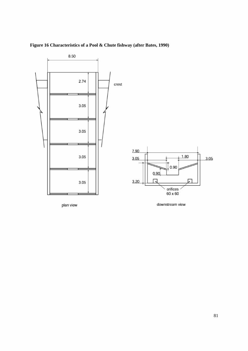
81
Figure 16 Characteristics of a Pool & Chute fishway (after Bates, 1990)

82
Suitable Species: Migratory salmonids, no data on other species
Head difference: Usually 0.15-0.30m
Length: 3.1m [7.9m wide = discharge 10m3s
-1]
Gradient: 10%
Flow: Up to 10m3s
-1
Discharge: As pool & traverse at low flow, criteria not available for high flow
Velocities: Similar to plunging flow passes at low flows, probably similar to V notch weirs at high
flows
Strengths: Designed to operate across a wide range of river discharges and upstream levels, high
energy dissipation values allowable at high flows
Weaknesses: As yet poorly documented. Not suitable for sites with drops >2m.
Shallow 'V' Notch Weirs
These pool passes have been used throughout Holland with some success, especially in small rivers
(Boiten, 1990). Sometimes in the river itself, but most often in by-pass channels parallel to the main
river. In essence these weirs form a series of pools where power is expended near each drop and
throughout the majority of the lower pool. Power dissipation per unit volume is generally low at
<100Wm-3
.
The fishway channel normally has a gradient around 3.33% to a maximum of 5.0%, however they
may be designed with lower gradients to accommodate higher flows (Larinier, 1992a). The low
gradients employed mean that these passes are effectively artificial rivers.
This type of pass has a limited ability to function at other than very modest changes in upstream level.
They are however particularly suitable for species of modest swimming performance, and, since they
can span the width of the river channel as artificial rivers, they can also exhibit very high measures of
efficiency.
In locations where they form only part of the river flow they are limited in their performance by their
attractiveness, and particularly the location of the downstream entrance if it is not immediately below
the obstruction.
These passes have a hydrometric standard discharge relationship and may be used as part of an ISO
Standard compound flow gauging & fish pass structure (BS ISO 26906:2009).

83
Example characteristics of the pools for several design flows are given in Figure 17 (after Larinier
1992a). These are applicable provided that the fishway operates at flows between 0.5Q and Q (i.e.
head between 0.75H1 and H1). The standard design can be scaled down or up to cater for discharges
between 0.35m3s
-1 and 5.50m
3-1. For precise hydraulic characteristics the reader should refer to the
original reference material.
Figure 17 Characteristics of a V-shaped pool fishway used in the Netherlands (after Boiten
1990).

84
Suitable Species: Migratory salmonids, coarse species at low head loss (<0.25m), generally all
surface swimming species. Not suitable for benthic species of coarse fish, eel or lamprey.
Head difference: 0.125-0.375m
Length: 3.75 - 11.25m pool width 5-15m
Gradient: normally 3.3% (max 5%)
Velocities: maximum behind the crest 1.74-3.02ms-1
, maximum in pool 0.53-0.92ms-1
both dependent
on gradient.
Strengths: Applicable to a wide range of fish species and sizes dependent on drop between pools. Not
prone to blockage. Tested designs shown to operate with relatively shallow pool depths of as little as
0.2m.
Weaknesses: Relatively low gradient therefore potentially high construction costs if not incorporated
into an existing structure. Capable of operation under only a very restricted range of upstream water
levels (generally range of 0.1-0.2m) since the maximum useful flow is set by the power dissipation in
the pools.
Baffle fishways
General
A Belgian engineer named Denil developed the first `baffle` fishway, in 1908 (Denil, 1909). Baffle
fishways consist of a straight sloping channel fitted with specific geometrically shaped deflectors
which cause helical currents to be developed thus dissipating the energy in the flow and reducing
velocities in a relatively large main through channel. The energy is very effectively and continuously
dissipated along the entire length of the pass. Fish can then swim straight up them provided that their
swimming capabilityis adequate.
Several different types of baffle are known to be effective in practice. Geometric characteristics of
baffles are given in a dimensionless form related to the width of the channel or else the height of the
baffle, and these should be rigidly adhered to since any amendment may cause substantial change to
the flow characteristics. Each type has a hydraulic operating range where the minimum flow provides
sufficient depth for helical currents to form (i.e. for the pass to charge), and the maximum is the flow
and/or gradient above which the helical structure breaks down and streaming flow develops.
This form of fishway is known not to be especially suitable for some species like shad, which do not
like the aeration in the water column because it obscures their vision of their compatriots, and
consequently are only ever likely to use them with low efficiency. It is also not especially suitable for
poor swimmers or small fish because of the relatively high velocities. However, some types of pass
are more adaptable than others, and velocities in all types can be restrained by using shallow slopes.
Apart from velocity another consideration is the size of the helical currents that are formed. The larger
the fish, the larger the helical current dimension (and thus baffle spacing/channel width) that it can
manage without being disorientated. Thus, small fish need small, closely spaced baffles.
Fish must pass the length of any one flight in a single attempt. Therefore the length of passage must
be limited to 10-12m (1.8m-2.4m) of drop, except for Alaskan ‘A’ type where up to 3m may be

85
considered for large migratory fish (i.e. salmon, sea-trout), and 6-8m (1.2-1.5m of drop) for trout and
cyprinids. Resting pools between lengths of pass must be provided to extend the overall height of
obstruction capable of being passed. Any one individual flight of baffled fishway must be in a straight
line, and the direction changed only at a resting pool.
Guidelines for suitable power densities and the calculation of power inputs and dissipation in rest
pools is given in the section on Additional Facilities – Resting facilities, page 180.
To avoid local acceleration in the vicinity of the entrance, or else the formation of a hydraulic jump at
this point, the downstream end of the fishway should be drowned equivalent to the depth (h) within it.
With the exception of Alaskan and Chevron type baffle passes the baffles are normally fabricated
from 10-12mm steel, and should not be thinner than 8mm. At a thickness less than 8mm the baffles
can vibrate, especially in plane baffle Denils, and this can dissuade fish from entering the pass.
Thinner baffles are also likely to be more abrasive for the fish. To avoid any prospect of injury should
fish bump into the baffles they should always be fully rounded on their edges. Galvanised mild steel is
usually adequate for most pass applications, particularly Super-active baffle passes that are always
drowned, however stainless steel may be necessary if the design life of the pass is more than 60 years
or if the pass is located in a salt water environment. Thicker baffles have been used, for example
wood, concrete and plastic (GRP). However they have generally been found to be unsatisfactory
because of limited durability. If employed maximum thickness should be L/20, where L is the unit
pass width.
To provide stable and smooth approach conditions a slope should be provided away from the invert of
the bed of the pass channel at the upstream end. A slope of 1:2 is recommended, though it may be as
little as 1:20. It is also beneficial to round the upstream ends of the side-walls of the pass channel to
retain a laminar flow pattern.
Idealised profiles for the head and intermediate resting pools are shown in Figure 18.
At the downstream entrance of the pass it will be an advantage, particularly for the more benthic
species of fish such as Barbel, to provide a slope that is contiguous with the river bed. This may also
be an advantage if applied, where space and volume for appropriate power densities to be maintained
allows, in the rest pools of those passes that have multiple flights.
The mean water velocity in any upstream exit channel should be between 0.3-0.5m/sec for coarse fish
and trout, and 0.3-1.0m/sec for migratory salmonids and shad.
Stop-log channels, or preferably a penstock, should be provided at the upstream end of the fishway to
facilitate closure for maintenance. Stop log channels may also be of benefit at the downstream end of
the pass.

86
Figure 18 Idealised profile for the head of the pass and intermediate rest pools for baffle passes
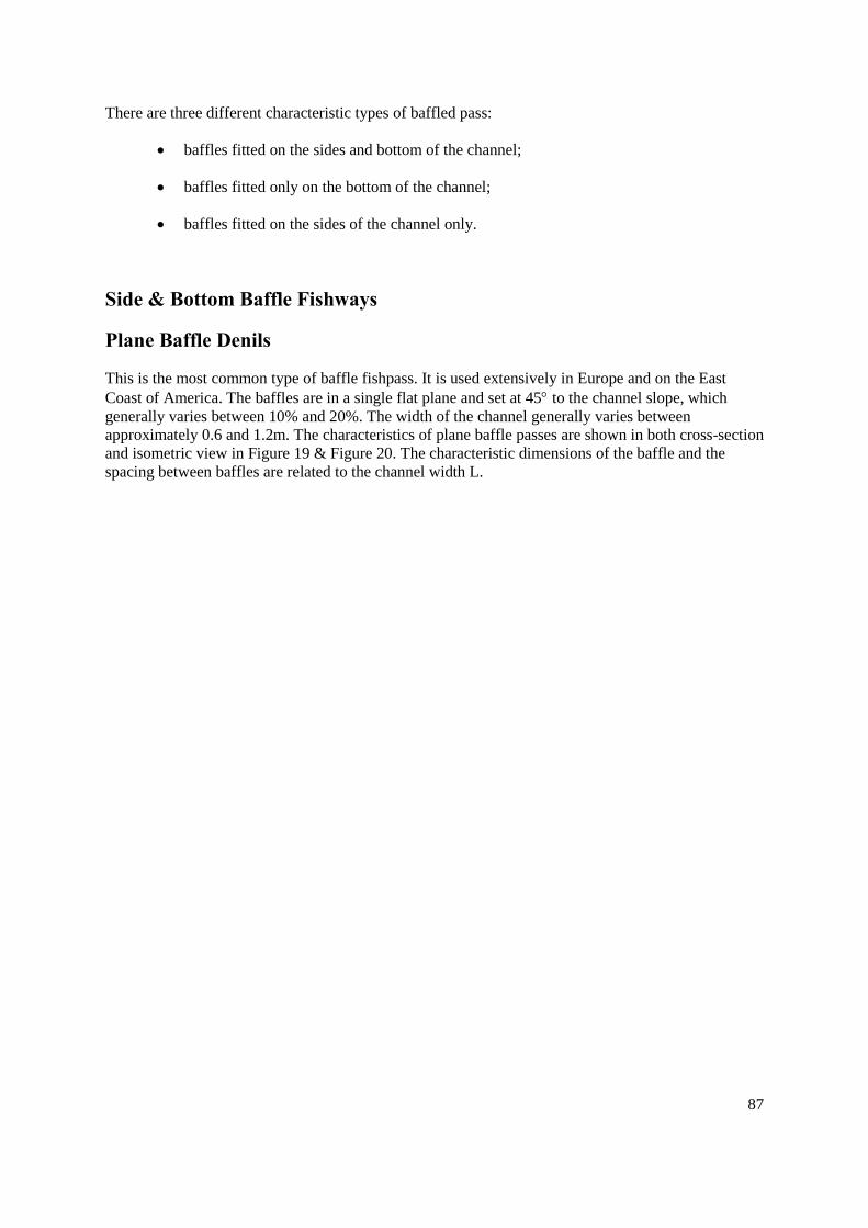
87
There are three different characteristic types of baffled pass:
baffles fitted on the sides and bottom of the channel;
baffles fitted only on the bottom of the channel;
baffles fitted on the sides of the channel only.
Side & Bottom Baffle Fishways
Plane Baffle Denils
This is the most common type of baffle fishpass. It is used extensively in Europe and on the East
Coast of America. The baffles are in a single flat plane and set at 45 to the channel slope, which
generally varies between 10% and 20%. The width of the channel generally varies between
approximately 0.6 and 1.2m. The characteristics of plane baffle passes are shown in both cross-section
and isometric view in Figure 19 & Figure 20. The characteristic dimensions of the baffle and the
spacing between baffles are related to the channel width L.

88
Figure 19 Cross-section and geometric characteristics of a plane baffle Denil fishway (After
Larinier 1992d)
89
Figure 20 Isometric view of a plane baffle Denil fishway (After Beach, 1984)

90
The invert of the pass is determined from the lowest point of the ‘V’ of the most upstream baffle
(Figure 16). The upstream head on the pass (ha) is the difference between the pass invert and the water
level upstream before any acceleration of flow. This should not be confused with hr, which is the
difference in level between the invert of the concrete slope on which the baffles are placed and the
upstream water level:
hr = ha + 0.236L sin(45 + arctan s)
where:
s = slope.
In short, for a slope of 10% hr = ha + 0.183L and for a 20% slope hr = ha + 0.196L.
The relationships between head, discharge and velocity in a plane baffle pass for three gradients are
shown in a dimensionless form in Figure 21. The actual relationships for the two most common
widths at the most common gradient are shown in Figure 22.
Plane Baffle Denils are usually deployed for migratory salmonids, however they can be used by a
variety of rough fish and shad (USA), coarse fish and lampreys (Europe,) and other native (Australia)
species by using shallow slopes around 10 – 12% or even less.
Fish of 45 – 630mm were shown to be able to utilise a PB Denil, and the whole size range of Bony
Herring, 45 – 350mm fork length were able to pass when the pass was at an 8.3% slope. Some 88%
of herring were able to utilise the fishway at the 8.3% slope, reducing to 31% when the pass was at a
20% slope. Performance was in between in thepass at a 14.3% slope. This paper, Mallen-Cooper &
Stuart, 2007, provides a useful review of the performance of Denils at different slopes and sizes.
Sea lampreys appear to be able to use PB Denils and certainly they have been trapped and sucker
marks are obvious at times on the baffles at the top of the Tees Barrage pass, R. Tees, UK (pers com
Richard Jenkins, personal observation). Sea lamprey passage in PB Denil passes in Ireland has also
been seen in videos on U-tube. While large numbers of river lamprey are seen in PB Denils in
Normandy, France when lowered to inspect traps (personal observation) it is not clear that they could
migrate under normal hydraulic operation.

91
Figure 21 Dimensionless relationship between upstream head (ha), mean depth in pass (h),
discharge (Q), and velocity (V) in a plane baffle fishway at 10, 15 & 20% slopes (After Larinier
1992d)

92
Figure 22 Relationship between between upstream head (ha), mean depth in pass (h), discharge
(Q), and velocity (V) in plane baffle fishways 0.6 & 0.9m wide at 20% slopes (After Larinier
1992d)
Plane Baffle 20% slope L=0.90m
Plane Baffle 20% slope L=0.60m

93
Suitable species: This type of pass is regarded as very suitable for large migratory species such as
salmon, sea-trout, and sea lamprey, and good swimmers such as trout and some of the larger riverine
coarse fish species. It is not regarded as very appropriate for small fish, which become disorientated
by the relatively large helical currents. Short lengths of shallow sloping channel 6-8m, 10-12%
gradients have been found to be fairly effective for "rough" species (can be translated as non-salmonid
species) in the north east of the USA and Canada.
Head difference: Single flights may be used to accommodate a head difference of up to a maximum
of 2.4m for large migratory salmonids, and 1.6m for other species.
Length & Gradient: Maximum gradient 20%. The length of any one flight should be limited to 12m
for migratory salmonids, and 8m for other species.
Width: Usually 0.8-1.2m for large migratory fish (salmon and sea trout), and 0.5-0.7m for smaller
migratory species (trout).
Depth: The lower operating limit is generally taken as h/L = 0.5 (where h = the depth in the pass from
the bed). This depth is necessary for the pass to develop the helical currents and to provide sufficient
space for fish to swim. The upper limit is not easily defined but a level of h/L of 1.1 is regarded as
reasonable.
Discharge: Would normally vary between about 0.25m3s
-1 and 0.75m
3s
-1 for large migratory
salmonids in a 0.9m wide pass. Larger discharges have been used in both 0.9m wide passes (up to
1m3s
-1) and wider units. For other species discharges of 0.1m
3s
-1 to 0.3m
3s
-1 in narrower passes would
be more typical. The discharge Q in the pass is given in a dimensionless form for head to pass width
ratios at various slopes in Figure 24, where Q* = Q/ (g.L2.5
).
Velocity: Mean velocities are generally constrained between 1.0-1.8m/sec dependent upon
dimensions, slope and discharge selected. Velocity profile in the pass in the vertical plane is variable
sinusoidally, being lowest at the bottom of the pass (approx. 80% of mean) and most rapid at the
water surface. The velocity V in the pass is given in a dimensionless form for head to pass width
ratios at various slopes in Figure 25, where V* = V/ (gL).
Strengths: Relatively simple to design and to construct, well understood and proven to be effective.
They can accommodate a modest range in upstream head, and provide a reasonable attraction flow in
many circumstances.
Weaknesses: Their major disadvantages are that they are very limiting in terms of the range of
species which they can effectively pass, and that they can be costly to maintain in an operational
condition because of the ease with which they can block with debris.
Fatou Denils
This type of fishpass has been used in France and is very efficient from a hydraulic point of view. It is
effectively an alternative to a plane baffle pass, and in most respects the limits of application are
similar. However, the baffles are difficult to construct because of their shape and the pass is very
prone to blockage. In addition, because of its hydraulic efficiency the relatively low water velocity
and discharge at the entrance limit its attractivity to fish. The characteristics of Fatou baffle passes are
shown in Figure 23.

94
The relationships between head, discharge and velocity in a Fatou baffle pass for three gradients are
shown in a dimensionless form in Figure 24. The actual relationships for the two most common
widths at the most common gradient are shown in Figure 25.
Figure 23 Cross-section and plan view of a Fatou baffle fishway (After Larinier, 1992d)

95
Figure 24 Adimensional relationship between upstream head (ha), mean depth in pass (h),
discharge (Q*), and velocity (V) in a Fatou baffle fishway at 10, 15 and 20% slopes (After
Larinier, 1992d)
Fatou Baffle 10% slope
Fatou Baffle 15% slope
Fatou Baffle 20% slope

96
Figure 25 Relationship between between upstream head (ha), mean depth in pass (h), discharge
(Q), and velocity (V) in Fatou baffle fishways 0.6 & 0.9m wide at 20% slopes (After Larinier,
1992d)
Fatou Baffle 20% slope
L= 0.60m
Fatou Baffle 20% slope
L= 0.90m

97
Suitable species: Suitable for migratory salmonids, sea lamprey, trout and some larger coarse fish
species. Probably less suitable for migratory salmonids and more suitable for coarse fish than a plane
baffle Denil.
Length & Gradient: Maximum gradient 20%. The length of a flight should be limited to 12m for
migratory salmonids, and 8m for other species.
Width: Usually 0.8-1.0m for large migratory fish (salmon and sea trout), and 0.5-0.7m for smaller
migratory species (trout).
Depth: The lower operating limit is generally taken as h/L = 0.4 (where h = the depth in the pass from
the bed). This depth is necessary for the pass to develop the helical currents and to provide sufficient
space for fish to swim. The upper limit is not easily defined but a level of h/L of 1.0 is regarded as
reasonable.
Discharge: Would normally vary between about 0.25m3s
-1 and 0.65m
3s
-1 for large migratory
salmonids in a 0.9m wide pass. For other species discharges of 0.1m3s
-1 to 0.24m
3s
-1 in narrower
passes would be more typical. The discharge Q in the pass is given in a dimensionless form for head
to pass width ratios at various slopes in Figure 24, where Q* = Q/ (g.L2.5
).
Velocity: Mean velocities are generally constrained between 0.85-1.25ms-1
dependent upon
dimensions, slope and discharge selected. The velocity V in the pass is given adimensionally for head
to pass width ratios at various slopes in Figure 24, where V* = V/ (gL).
Strengths: Hydraulically efficient and can withstand a modest increase in upstream head.
Weaknesses: Very prone to blockage with debris, limited attractivity especially for migratory
salmonids because of the low kinetic energy of the jet at the pass entrance.
Alaskan 'A' Denils
This type of fishpass with 3-dimensional baffles is a very specific type of pass originally developed
for passing Pacific salmon in remote areas. Its box-like construction from 6mm aluminium made it
strong and light for air-lifting, and thus facilitated fitting to remote natural barriers. Sections, usually
1-3m, long were prefabricated and then bolted together on site.
The channel has fixed dimensions in terms of width and baffles and is narrow (0.56m) with a small
free passage width (0.35m). It is used in depths from 0.7 to 1.4m. Modular units in 1m lengths and
heights of 0.7m, 1.0m and 1.4m are available commercially in the UK.
It is more effective hydraulically than a similarly sized plane baffle pass operating at a similar depth,
passing less flow at a lower velocity. The baffles are closely spaced making the size of helical
currents in the pass relatively small. The characteristics of the Alaskan `A` pass are shown in figures
Figure 26 & Figure 27 .

98
Figure 26 Plan and cross-section, giving the geometric characteristics of an Alaskan `A` fishway
(After Larinier, 1992d)
Figure 27 Isometric view of an Alaskan `A` fishway (After Larinier, 1992d)
y o
b =

99
Steepasses with lengths from 9.1m to 27.4m and slopes ranging from 19.7% to 26.2% have been used
to successfully pass coho, pink, and sockeye salmon in Alaska, and the same species together with
steelhead for length sup to 20.1m in the Columbia River, USA (Slatick & Basham, 1985). Model A
Alaskan passes with lengths ranging from 9.1 – 20.1m, slopes 23.3 – 28.7% passed a range of non-
salmonid species though some species were restricted by the challenge, so that for example carp could
only manage lengths less than 15m lengths, while northern sqawfish, American shad, and suckers
could not manage 20m. Adult Pacific salmon, Pacific Sea lamprey, and steelhead could manage 27m.
American shad (Alosa sapidissima) and White Sucker (Catostomous commersoni) could pass a Model
A40 Alaskan Steeppass (upto 90cm deep, 45cm free gap) at a 12.5% slope with more than 50%
efficiency provided it was a single straight run and around 12m long. However, if a turning pool was
introduced (curve same width as channel turning through 180 degrees) the efficiency was more than
halved. There were also indications of damage suffered by the fish, especially where fallback
behaviour occurred (Haro, Castros-Santos, & Noreika, 2004).
Athough likely to be useable by coarse fish, particularly at slopes ≤ 20%, apart from a site at the Dog-
and-Doublet, Anglian Region which is tidally influenced and passed by a range of species and sizes of
coarse fish, there is little documented information on passage of coarse fish in Alaskan As.
Suitable species: They are very suitable for migratory salmonids and trout, probably suitable for sea
lamprey, and for some larger coarse fish species. The relatively low velocities and small helical
currents also makes these passes useful for larger coarse fish species, provided that gradients 20%
are used.
Head difference: In exceptional circumstances single flights may be used to accommodate head
differences up to 3.0m for migratory salmonids, and 1.6m for other species.
Length & Gradient: Gradients used for this type of pass can be steep (hence it is often called a
steeppass), and slopes up to 33% have been used. However, it is not recommended to use a gradient
steeper than 25% for migratory salmonids and 20% for other species. A single flight should not
exceed 12m for salmonids and 8m for other species.
Width: The channel has fixed dimensions in terms of width and baffles, and is narrow (0.56m) with a
small free passage width (0.35m).
Depth: The lower operating limit of depth yo (Figure 23) for large migratory salmonids is generally
taken as about 0.1m3-1
or 0.325m for a pass at a 25% slope. The upper limit is not easily defined but
should certainly not exceed 1.27m.
Discharge: Can range between 0.1m3s
-1 and 0.81m
3s
-1, most often being around 200-450ls
-1.
Discharge Q = 0.97. b0.95
. s0.5
. yo1.55
.g0.5
, or for a pass of standard width 0.35m (Figure 23) Q = 0.3578.
s0.5
. yo 1.55
. g 0.5
. Where s = the tangent of the angle between the slope and the horizontal.
Velocity: Mean velocities are usually between 1.1-1.4 ms-1
(for slopes between 20-33% and
depending on depth). Velocity varies in the vertical plane, being highest at the bottom and slowest at
the surface for depth values yo/b 1.20. For values greater than this the maximum velocity drifts away
from the bottom towards the mid-depth line. Mean velocity V = Q/b. yo
Strengths: Well-tried and tested and commercially available as pre-fabricated modular units.
Accommodates a modest increase in upstream head, provides passage at relatively low flows, and at

100
slightly lower velocities than other Denils. May be considered for head differences up to 3m without a
rest pool, and for gradients up to 25%.
Weaknesses: The disadvantages of this type of pass are the likelihood of blocking, and the relatively
limited discharge that reduces its attractivity because of the low kinetic energy of the jet at the pass
entrance. In many watercourses augmentation of attraction flow would frequently have to be
considered.
Bottom Baffle Fishways
Super-active baffle (Larinier) pass
This type of pass, developed by Larinier and Miralles in the early 1980's (Larinier & Miralles, 1981)
is coming to be widely used in Europe and Britain. There is increasing evidence that this type of pass
is suitable not only for large migratory salmonids such as salmon and sea trout, but also for an
extensive range of other species including brown trout, grayling, and coarse fish. For example some
sixteen different species, ranging from salmon to gudgeon, have been recorded using such a pass in
the Thames catchment. This includes many small coarse fish 11-20cms in length, that must have been
exploiting low velocity areas within the fishway. It is therefore quite clear that fish are very clever at
exploiting the heterogeneity of micro-velocities in this type of fishway.
It is a relatively wide and shallow type of fish pass (by comparison with Denils), and only has baffles
on the bed of the pass. Channel width is only limited by site conditions and not by hydraulic operating
characteristics as is the case for other types of baffled fishpass. A significant advantage of this type of
fishway is that major attraction flows can be created, by juxtaposing multiple `units` of pass in to a
very wide channel.
Baffle height is variable between 0.08-0.20m with recommended heights between 0.075-0.10m for
trout and coarse fish, and 0.10-0.20m for salmon and sea trout. The characteristics of Larinier passes
are shown in plan & cross-section in Figure 28, and isometric view in Figure 29. The characteristic
dimensions of the baffles and the baffle spacing are a function of the baffle height, so that the width of
one baffle unit = 6.a and the space between baffles = 2.6.a, where a = the height of the baffle.
Baffles are generally fabricated from 10 – 12mm thick galvanised mild steel, sometimes stainless
steel, with fully radiused top edges. Other materials have also been used, including for example, green
oak baffles where the wood has been obtained from sustainable sources – though this has usually
been at sites regarded as easements rather than where expensive permamnent technical solutions are
being employed.

101
Figure 28 Geometric characteristics of a Super-active baffle (Larinier) fish way (After Larinier,
1992d)
Figure 29 Isometric view of a Super-active baffle (Larinier) fishway
102
The invert of the pass is determined from the straight lateral piece of the most upstream baffle. The
upstream head on the pass (ha) is the difference between the pass invert and the water level upstream
before any acceleration of the flow.
hr = ha + a - 2.6. a. s
where:
s = slope = the tangent of the angle between the slope and the horizontal.
The mean depth of water in the pass (h) is the depth above the baffles.
The relationships between head, discharge and velocity in a Super-active baffle pass for two gradients
are shown in a dimensionless form in Figure 30. The actual relationships for the two most common
baffle heights at the most common gradient are shown in Figure 31. Since the width of the fishway
may vary considerably the latter figure gives discharge as a unitary measure (m3/s/m), total discharge
is obtained by multiplying by the actual width.
Lariniers may be adapted for joint use by canoes by modifying some of the construction details. The
following adaptations were agreed with the British Canoe Union (BCU) and employed for a fish pass
on Haverfordwest Town Weir, R. Western Cleddau, Wales (constructed in 2003):
Pass to be a minimum of 1.4m wide
Baffles to be 20mm thick and fully rounded profile on their tops (normally 10 -12mm fully
rounded)
Minimum depth Ha on the pass to be 300mm
Tops of pass side-walls to be rounded
Side-walls of pass at upstream to rake down into the (minimum) head water level at an angle
of 45° or less
Grab chains to be provided at the upstream end of the pass
Preferably the pass to consist of an odd number of units juxtaposed, minimum three, so that
the middle of the pass offers a higher velocity lead for the canoe.
This pass consisted of a single flight of Larinier. Where multiple flights are used and rest pools are
required, particularly if they are used to turn the pass, consideration will need to be given to the length
of the pool. Although not especially adapted for canoes, paddlers are known to enjoy using the large
Larinier (3.6m wide with 6m rest pool used to turn the pass) on the River Dove in Midlands Region.

103
Figure 30 Dimensionless relationship between upstream head (ha), mean depth in pass (h),
unitary discharge (q*), and the average water velocity (V*) in a Super-active baffle fishway at
10% and 15% slopes (After Larinier 1992d)
Superactive baffles Slope = 10%
Superactive baffles Slope = 15%

104
Figure 31 Relationship between upstream head (ha), mean depth in pass (h), unitary discharge
(q), and velocity (v) for 0.10m & 0.15m high super-active baffle fishways at 15% slope (After
Larinier 1992d)
Superactive baffles Slope = 15% a=0.10m
Superactive baffles Slope = 15% a=0.15m

105
Suitable species: This type of pass is regarded as suitable for a wide range of species including
salmon, sea trout, sea lamprey, trout, grayling, and coarse fish.
Head Difference: Single flights may be used to accommodate head differences up to a maximum of
1.5-1.8m for large migratory salmonids and a maximum of 1.2-1.5m for coarse fish species.
Length & Gradient: Maximum gradient 15%. Generally the gradient used is between 10% and 15%,
although it can be less. The length of any one flight should be limited to 12m for migratory salmonids
and 8-10m for other species.
Depth: The lower operating limit is generally taken as h/a = 1.15 (where h = mean depth over the
baffles in the pass and a = the height of the baffle), which depth is necessary for the fishway to
develop the necessary hydraulic characteristics. Minimum depths h in the pass for large migratory fish
and trout/coarse fish to swim should be taken as 15-20cm and 10-15cm respectively. The upper limits
of operation in terms of ha (head on top baffle) are approximately 0.5m for trout and coarse fish
(100mm or 150mm baffle) and 0.6m & 0.9m for large migratory salmonids (100mm & 150mm baffle
respectively).
Width: The width of any one unit of pass is a function of the chosen baffle height (L = 6.a). Passes
are not normally less than 0.6m wide (i.e. 100mm high baffle, single unit), but smaller ones might be
considered where available flows and head ranges are very low.The most commonly used baffle
heights are 100mm and 150mm, with pass widths typically 0.6-1.8m. Half widths of unit may be used,
thus a fishway might be 1.5 or 2.5 units wide etc. The largest passes currently in the UK are 3.6m
wide i.e. 6 juxtaposed units of 100mm baffles, or 4 juxtaposed units of 150mm baffles.
Discharge: It is recommended that operating range is taken as between 0.15-0.65m3s
-1m for trout and
coarse fish and 0.25 - 1.50m3s
-1m for migratory salmonids (where m
3s
-1m is cubic
metres/second/metre width of pass). Significant discharges can be attained in the fishway by
juxtaposing several units of pass together. The overall width of the fishway is limited only by; the
flow available to be used, the physical limits of any structure that it is in, the increased difficulty of
shutting a wide pass for maintenance, and the cost. If pass units are juxtaposed then a plate, the same
height as the baffles, must be inserted between each one. The unitary discharge in the pass is given
adimensionally for head to baffle height ratios at two different slopes in Figure 30, where q* = q/(
2g.a1.5
). Total discharge Q = 6 a N q, where N = number of juxtaposed units, and q = unitary
discharge per metre of pass.
Velocity: Mean velocities are generally constrained between 1.0-1.5ms-1
for coarse fish species and
non-migratory trout and 1.3-2.0ms-1
for migratory salmonids dependent on dimensions, slope and
discharge selected. The velocity in the pass is given adimesionally for head to baffle height ratios at
two different slopes in Figure 30, where V* = aq*/h.
Strengths: Suitable for a relatively wide range of species and sizes of fish. Major advantages over
other types of Denil are that they are much more unlikely to block (because they have only bottom
baffles) and therefore less of a maintenance risk, and that major attraction flows can be provided by
juxtaposing multiple units of baffles to create wide fishways. With suitable modifications to design
details may be used by canoes.
Weaknesses: Their main disadvantage is the sensitivity to change in head level which means that they
will not generally remain effective if head rises more than about 200-300mm above normal operating
level in 100mm baffle passes, or 400 – 500mm above normal operting level in 150mm passes.

106
Chevron baffles
This type of pass has been used in France as a dual-purpose fish and canoe way (Larinier, 1984).
Thick wooden baffles are used on the bottom of the pass in place of the thinner metal baffles used in a
super-active fishway. This is in order to make the pass more 'boat-friendly'. Owing to the high
velocities in this type of pass, which also increase rapidly as a function of depth, these type of
fishways are only suitable for large salmonids, sea lamprey, and very large coarse fish such as barbel.
The baffles are arranged in 'arrow shaped' sections that are juxtaposed across the bottom of the
fishway. They are generally constructed of 10-12cm (minimum 8cm, maximum 15cm) square section
timber. Longitudinal strips between each chevron are used to help stabilise the flow and increase the
`boat-friendliness` of the facility. Where the facility is only to be used by fish it is possible to exclude
all the longitudinal strips except for the central one along the axis of the pass, which is required to
stabilise the flow pattern.
For boat passage the arrangement of the chevrons is revised so that the centre of the passage facility
corresponds to the upstream point of the V. This facilitates boat passage by ‘guiding’ them in to the
centre of the fishway.
Like the Larinier Super-active type of pass, many units can be juxtaposed to increase total fishway
discharge. If boats are to use the pass then it must have a minimum width of 1.4-2.1m.
The characteristics of Chevron baffle fishway are shown in plan & cross-section in Figure 32.

107
Figure 32 Geometric characteristics of a Chevron baffle fishway (After Larinier 1992d)
108
The invert of the pass is determined from downstream side of the uppermost point of the first baffle.
The upstream head on the pass (ha) is the difference between the pass invert and the water level
upstream before any acceleration of the flow.
hr = ha + a - 3a s
where:
s = slope
The mean depth of water in the pass (h) is the depth above the baffles.
The relationships between head, discharge and velocity in a Chevron baffle pass for two gradients are
shown in a dimensionless form in Figure 33. The actual relationships for at baffle height of 0.1m, at
the most common gradient of 15%, is shown in Figure 34. Since the width of the fishway may vary
considerably the latter figures provide discharge as a unitary measure (m3s
-1m
-1), total discharge is
obtained by multiplying by the actual width.

109
Figure 33 Dimensionless relationship between upstream head (ha), mean depth in pass (h),
unitary discharge (q*), and velocity (V*) in a Chevron baffle fishway at 10% and 15% slopes
(After Larinier, 1992d)
Chevron Baffle
Slope = 10%
Chevron Baffle
Slope = 16%

110
Figure 34 Relationship between upstream head (ha), mean depth in pass (h), unitary discharge
(q*), and velocity (V*) for a 0.10m high chevron baffle fishway at a 15% slope (After Larinier,
1992d)
Chevron Baffle Slope = 10%
Chevron Baffle Slope = 16%

111
Suitable species: This type of pass is generally only suitable for large salmonids >40cms in length.
May accommodate sea lamprey and very large coarse fish.
Head Difference: Single flights may be used to accommodate head differences up to a maximum of
1.5-1.8m.
Length & Gradient: Maximum gradient 15%. Generally the gradient used is between 10% and 15%,
although it can be less. The length of any one flight should be limited to 12m.
Depth: The minimum operating depth for large migratory fish should be taken as 30cms. The upper
limit of operation in terms of ha (head on top baffle) is approximately 0.65m.
Width: The width of the pass is a function of the chosen baffle height. Passes would normally be a
minimum of 1.4m wide (i.e. minimum of 100mm high baffle),but may be substantially wider.
Discharge: The unitary operating range is between 0.25 – 0.90m3s
-1m for migratory salmonids.
Significant discharges can be attained in the fishway by juxtaposing several units of pass together.
The overall width of the fishway is limited only by; the flow available to be used, the physical limits
of any structure that it is in, the increased difficulty of shutting a wide pass for maintenance, and the
cost. The unitary discharge in the pass is given adimensionally for head to baffle height ratios at two
different slopes in Figure 33, where q* = q/ (2g.a1.5
). Total discharge is given by multiplying the
width by the unitary value.
Velocity: Mean velocities are generally constrained between 1.5-2.2ms-1
for large migratory
salmonids, dependent on dimensions, slope and discharge selected. The velocity in the pass is given
adimesionally for head to baffle height ratios at two different slopes in Figure 33, where V* = aq*/h.
Strengths: Capable of dual use as fish pass and canoe/kayak pass. Unlikely to block and therefore
low maintenance risk. Significant attraction flows can be provided, by juxtaposing multiple units of
baffles.
Weaknesses: Significant disadvantages of only being suitable for large migratory salmonids (>40cm
length) or very large individuals of some of the very fastest swimming riverine species, and only
operating effectively over a very limited range in head.
Side Baffle Fishways
Side-baffle only fishways have had very limited use and little is known about their performance or
characteristics. It is unlikely that they would be suitable for any species other than large migratory
salmonids. While many configurations of baffle may be possible from simple bands (Anon, 1942) to
complex shapes (Larinier & Miralles, 1981), it is only the latter that would be considered for use in
modern times. These are described below.

112
Chevron Side Baffles
A relatively simple design, consisting of rows of chevron shaped baffles on the sides of a relatively
narrow channel, was described and tested hydraulically by Larinier & Miralles (1981). Average water
velocities are relatively high (>2ms-1
) in this type of pass, and they are therefore unsuitable for species
other than large migratory salmonids. However, the velocity in the water column remains fairly
constant, at least up to a depth equivalent to twice the width of the pass, and this hydraulic behaviour
may be advantageous at sites where a large range in upstream water level is expected during the
period of fish pass operation.
Passes of this type has been used at Radyr Weir on the River Taff in Cardiff and Stoke Lock on the
River Itchen. Although velocities range from about 2ms-1
(low discharge) to as high as 3ms-1
(design
discharge), the passes appear to work well for salmon and sea trout (P. Gough, A. Fewings pers
comm).
The characteristics of Chevron Side-Baffle fishway are shown in plan & cross-section in Figure 35.

113
Figure 35 Geometric characteristics of a Chevron Side Baffle fishway (After Larinier &
Miralles, 1981)
Plan view
Invert of the fish pass Side view A-A
Slope I

114
Figure 36 Dimensionless relationship between upstream head (ha), mean depth in pass (h), and
discharge (q) in a Chevron side baffle fishway at 10%, 15% and 20% slopes (After Larinier &
Miralles, 1981)
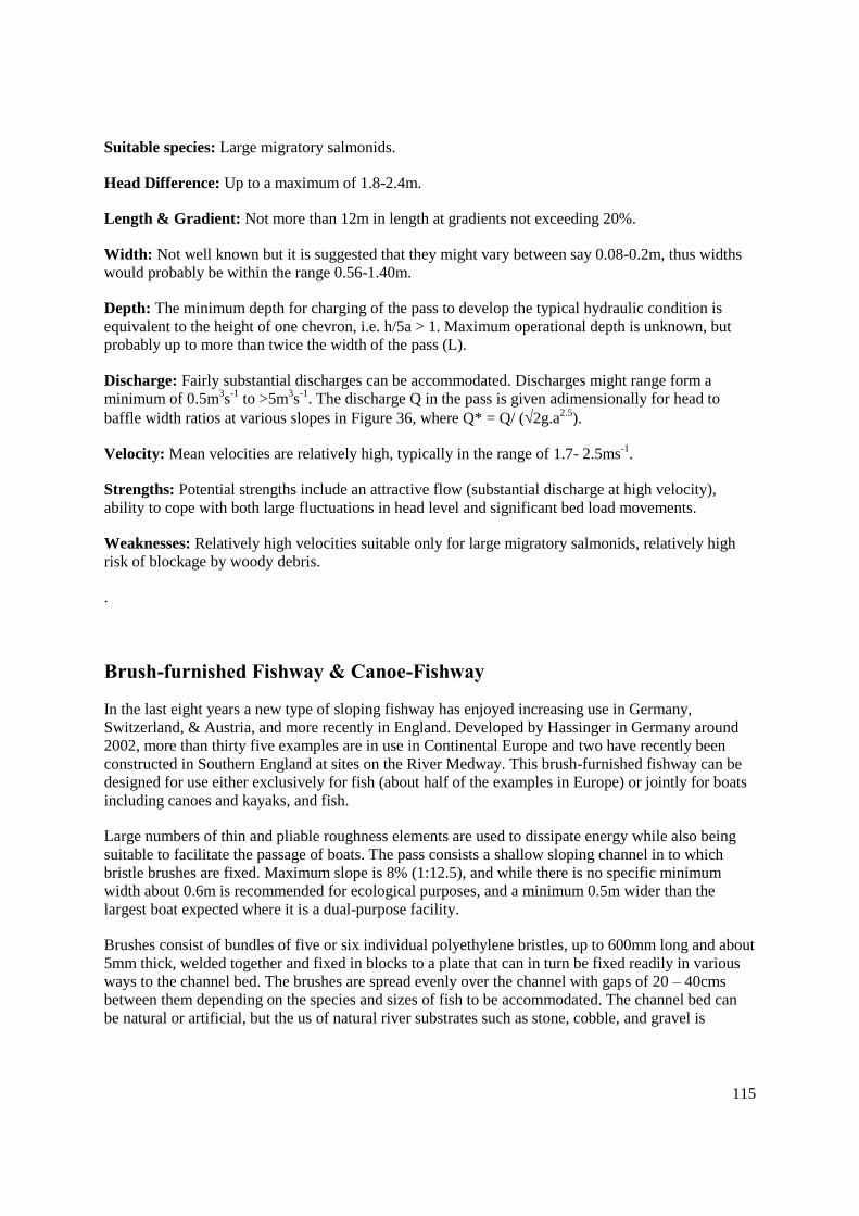
115
Suitable species: Large migratory salmonids.
Head Difference: Up to a maximum of 1.8-2.4m.
Length & Gradient: Not more than 12m in length at gradients not exceeding 20%.
Width: Not well known but it is suggested that they might vary between say 0.08-0.2m, thus widths
would probably be within the range 0.56-1.40m.
Depth: The minimum depth for charging of the pass to develop the typical hydraulic condition is
equivalent to the height of one chevron, i.e. h/5a > 1. Maximum operational depth is unknown, but
probably up to more than twice the width of the pass (L).
Discharge: Fairly substantial discharges can be accommodated. Discharges might range form a
minimum of 0.5m3s
-1 to >5m
3s
-1. The discharge Q in the pass is given adimensionally for head to
baffle width ratios at various slopes in Figure 36, where Q* = Q/ (2g.a2.5
).
Velocity: Mean velocities are relatively high, typically in the range of 1.7- 2.5ms-1
.
Strengths: Potential strengths include an attractive flow (substantial discharge at high velocity),
ability to cope with both large fluctuations in head level and significant bed load movements.
Weaknesses: Relatively high velocities suitable only for large migratory salmonids, relatively high
risk of blockage by woody debris.
.
Brush-furnished Fishway & Canoe-Fishway
In the last eight years a new type of sloping fishway has enjoyed increasing use in Germany,
Switzerland, & Austria, and more recently in England. Developed by Hassinger in Germany around
2002, more than thirty five examples are in use in Continental Europe and two have recently been
constructed in Southern England at sites on the River Medway. This brush-furnished fishway can be
designed for use either exclusively for fish (about half of the examples in Europe) or jointly for boats
including canoes and kayaks, and fish.
Large numbers of thin and pliable roughness elements are used to dissipate energy while also being
suitable to facilitate the passage of boats. The pass consists a shallow sloping channel in to which
bristle brushes are fixed. Maximum slope is 8% (1:12.5), and while there is no specific minimum
width about 0.6m is recommended for ecological purposes, and a minimum 0.5m wider than the
largest boat expected where it is a dual-purpose facility.
Brushes consist of bundles of five or six individual polyethylene bristles, up to 600mm long and about
5mm thick, welded together and fixed in blocks to a plate that can in turn be fixed readily in various
ways to the channel bed. The brushes are spread evenly over the channel with gaps of 20 – 40cms
between them depending on the species and sizes of fish to be accommodated. The channel bed can
be natural or artificial, but the us of natural river substrates such as stone, cobble, and gravel is

116
recommended in order to increase roughness and habitat heterogeneity even further. In this way the
channels can accommodate passage of fish, other vertebrates, and invertebrates, while also harbouring
invertebrate and fish populations as well.
The mean velocity is constant for different depths of water column up to the level of the tips of the
bristles, after which velocities will increase with increasing drowning. Mean velocity among the
bristles is very low, and a function of the density of the bristles and slope of the channel, while that in
the gap between brushes follows the conventional equation where Vmax = 2gDH0.5
. Given that the
slope is low and the head drop between series of brushes only typically about 4 – 5cms, maximum
velocity is usually ≤1.0ms-1
, while mean velocity across the fishway as a whole is about 0.5ms-1
.
Figure 37 Head discharge relationship for a fishway with 47cm long bristles (after Hassinger &
Kraetz, 2006)
0
100
200
300
400
500
600
0 50 100 150 200 250 300
Specific discharge [l/s/m]
Wa
ter
de
pth
[m
m]
level of bristle tips
(bristle length 470mm, bristle density 1110 m-2
, dimeter 4-6mm overall, slope 1:25)
Clearly, total discharge is related to the size of the structure constructed but will be lower than a
conventional pass in terms of the equivalent cross-section. Using 0.5ms-1
average water velocity
discharge can easily be approximated e.g. a 0.5m deep x 1.2m wide pass will discharge 0.30m3s
-1,
whereas a 0.3m deep x 0.6m wide pass will discharge 0.09m3s
-1.
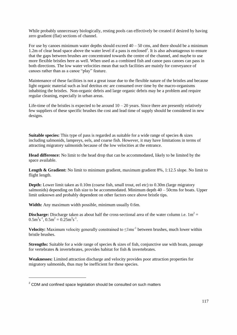
117
While probably unnecessary biologically, resting pools can effectively be created if desired by having
zero gradient (flat) sections of channel.
For use by canoes minimum water depths should exceed 40 – 50 cms, and there should be a minimum
1.2m of clear head space above the water level if a pass is enclosed2. It is also advantageous to ensure
that the gaps between brushes are concentrated towards the centre of the channel, and maybe to use
more flexible bristles here as well. When used as a combined fish and canoe pass canoes can pass in
both directions. The low water velocities mean that such facilities are mainly for conveyance of
canoes rather than as a canoe “play” feature.
Maintenance of these facilities is not a great issue due to the flexible nature of the bristles and because
light organic material such as leaf detritus etc are consumed over time by the macro-organisms
inhabiting the bristles. Non-organic debris and large organic debris may be a problem and require
regular cleaning, especially in urban areas.
Life-time of the bristles is expected to be around 10 – 20 years. Since there are presently relatively
few suppliers of these specific brushes the cost and lead time of supply should be considered in new
designs.
Suitable species: This type of pass is regarded as suitable for a wide range of species & sizes
including salmonids, lampreys, eels, and coarse fish. However, it may have limitations in terms of
attracting migratory salmonids because of the low velocities at the entrance.
Head difference: No limit to the head drop that can be accommodated, likely to be limited by the
space available.
Length & Gradient: No limit to minimum gradient, maximum gradient 8%, 1:12.5 slope. No limit to
flight length.
Depth: Lower limit taken as 0.10m (coarse fish, small trout, eel etc) to 0.30m (large migratory
salmonids) depending on fish size to be accommodated. Minimum depth 40 – 50cms for boats. Upper
limit unknown and probably dependent on other factors once above bristle tips.
Width: Any maximum width possible, minimum usually 0.6m.
Discharge: Discharge taken as about half the cross-sectional area of the water column i.e. 1m2 =
0.5m3s
-1, 0.5m
2 = 0.25m
3s
-1.
Velocity: Maximum velocity generally constrained to ≤1ms-1
between brushes, much lower within
bristle brushes.
Strengths: Suitable for a wide range of species & sizes of fish, conjunctive use with boats, passage
for vertebrates & invertebrates, provides habitat for fish & invertebrates.
Weaknesses: Limited attraction discharge and velocity provides poor attraction properties for
migratory salmonids, thus may be inefficient for these species.
2 CDM and confined space legislation should be consulted on such matters

118
Active Fish Elevators
Fish Locks
A fish lock operates on the same principle as a navigation lock in order to secure the passage of fish
over an obstruction. Fish locks in use are almost invariably of the Borland lift variety, which was first
tried out in Ireland and Scotland in the 1940's and 1950's. Borland lifts are now installed at several
hydropower dams in Scotland and at a smaller number of sites in Wales. They usually consist of a
sloping or vertical cylinder constructed as an integral part of the dam structure (or in a few instances
as a later addition to the structure), which connects two pools, one located at the upstream level and
one at the downstream level. The pools are each provided with a sluice gate that controls the operation
of the structure. Fish are encouraged to accumulate in the lower pool before they are trapped and
lifted to the higher level by filling the connecting conduit. Most Borland lifts have been installed in
dams of 6m to 18m in height, although some examples are on dams of up to 42m high (Aitken et al,
1966), or as little as 4-5m high (Travade & Larinier, 1992). There are four distinct operational stages:-
an attraction stage in which the upper and lower control gates are both open and
water flows through the lock structure to attract fish into a holding chamber. The
conditions for fish attraction are those used conventionally for pool passes.
a filling stage in which the fish entrance gate is closed and the incoming water, either
directly from the headwater gate or indirectly into the lower part of the chamber via a
valve, causes the water level within the lock to raise and equilibrate with the upstream
level. Fish are required to rise up through the body of the lock chamber in this stage
a fish exit stage during which the lower gate is partially opened and the upper water
inlet gate is manipulated to provide an attractive flow of water to entice fish to leave
the lock. The fish then have the opportunity to leave the lock chamber and enter the
upstream water body.
an emptying stage during which the upstream gate is raised above the upstream
forebay water level, allowing the lock to empty slowly.
The characteristics of a typical fish lock and its operational cycle are shown in Figure 38 & Figure 39.

119
Figure 38 The plan and cross-section of a typical fish lock (after Aitken et al, 1996)

120
Figure 39 The operating cycle of a fish lock (after Travade & Larinier, 1992a)

121
The timing of the operating cycle should be adapted to enable it to correlate closely with the number
and species of fish wishing to ascend, and the timing and pattern of their migration. Typically this
may involve fishing stages of about two hours, followed by appropriate length of time filling and a
fish exit stages of about one to two hours. Operating practice has also indicated that the hydraulic
conditions during the fish exit stage are crucial to passage effectiveness, and that fish must be
encouraged to leave the chamber by carefully manipulating flows and relative water levels. A head
difference of up to 15 inches has been quoted as optimum (Aitken et al, 1966). There can be a
tendency in practice for the number of cycles to be reduced, for example to as few as two automatic
cycles per day. However it should be noted that failure to optimise the timing of the cycle is
frequently the cause of reduced operating efficiency.
Monitoring of the effectiveness of fish locks has been carried out at one of the Borland Lifts in the
Beauly and the Conon system, Scotland (Forbes et al, 1996, 1999, 2000 & 2002; Gowans et al, 2003
respectively) . In the Beauly, the behaviour of 10 radio tagged salmon was examined immediately
below a functioning Borland lift. Fish were found to make series of brief visits to the vicinity of the
pass, sometimes entering the holding chamber. However only 5.3% of such visits into the chamber
resulted in fish ascending the lift during the fill cycle. Of these, 80% successfully left the pass and
entered the headwater. The later studies were carried out with the objective of recommending
improved operating practices (Johnstone, pers.comm.). Adjusting attraction flow upwards, provided it
was not too high, increased numbers of fish entering the lower chamber. Efforts to increase passage
by making the upstream exit more visible to fish, and increasing the number of lift cycles form three
to four a day made no significant difference to performance. On the Conon fish passage efficiency in
the Borland Locks was very modest at around 63%, and fish were delayed by up to 52 days.
The difficulty of encouraging fish to exit the chamber after the filling stage, noted by Larinier (1990),
is one reason why locks are now rarely considered for use in France. Larinier & Travade (1992) have
demonstrated other problems associated with the difficulty of establishing optimum hydraulic
conditions and in maximising the efficiency of passage for fish which do enter the holding chamber.
These include lack of attraction and the need for augmentation flow, excessive turbulence in the
downstream pool, poor lighting conditions, insufficient residence time in the lower pool, and the
possibility of fish being washed away from the vicinity of the entrance to the pass during the
emptying stage. Furthermore it is evident that no fish can enter the structure during the filling and fish
exit stages - this is the main reason why two parallel locks were proposed for the Usk barrage.
Strengths: Overall, fish locks clearly offer a partial solution to fish passage issues related to high
head dams, where more conventional pool passes are not feasible.
Weaknesses: Disadvantages include: modest efficiency, the relatively high capital cost, their
sensitivity to head water level variation, the difficulty of establishing optimum operating protocols,
and the discontinuous nature of their operation.
Fish Lifts
A fish lift operates on the principal of a conventional elevator. There are three distinct operational
stages:-
an attraction stage in which water flows through a holding pool part of which forms a transport
tank, or else from which fish can be crowded into a tank further along a channel. In practice this
often involves the use of guide screens and re-entrant devices to maximise retention of fish which

122
enter the structure. The conditions for fish attraction are those used conventionally for pool
passes.
a lifting stage in which the transport tank ascends on guide rails to the top of the dam
a fish exit stage in which the tank is tipped so that fish are discharged either directly in to the
headwater, or else into a channel to carry them a safe distance upstream thus helping prevent
passage back downstream.
Effectively there are two types of facility, the choice of which depends on the number and species of
fish that are being moved. Lifts with integral tanks are used for robust species that tend to arrive at the
facility in relatively low numbers at any one time, such as migratory salmonids. Lifts that employ
mechanical crowders and large holding pool areas are used where fish arrive in large numbers, or else
for the more delicate species, such as shad.
An excellent description of the design features and principles of such facilities is provided by Travade
& Larinier (1992). This includes selection of type of lift, siting, water supply, dimensioning of the
holding pool and the lifting tank, crowding device, fish emptying and transfer, size and operation, and
care and maintenance.
There is no known example of a fish lift in the UK, however they are widely used in France and the
USA (Travade and Larinier, 1992), particularly where large numbers of shad are involved.
Strengths: Fish lifts have the advantages that, compared to other facilities at high head obstructions,
they take little space, are cheaper to construct, are relatively insensitive to head water level variations,
and can easily be adjusted for any dam height. They are also suitable for a wide range of species,
including some like pike that have difficulty using other conventional types of fishway.
Weaknesses: The reliance on mechanical systems means that the costs of operation and maintenance
are relatively high, and that a programme of ongoing maintenance is essential to avoid restricting
availability. Availability is anyway limited by the operational cycle.
Venturi Pump Fishway
Venturi fish pass pumps are an innovation designed by Gerard Manshaden c. 2005. In the Netherlands
more than 3000 pumps are used operationally to manage land drainage, pumping water from lower-
lying polders to higher water channels. These pumping operations can be responsible for the mortality
of virtually all of the fish passing the pump, which millions of fish naturally do as part of their
‘downstream’migrations in these channels.
In essence the FishFlow Fishway is a venturi system applied to conventional pumps in pumping
stations. The venturi is located behind a conventional pump where the discharge is forced through a
narrow aperture inducing a high velocity jet that creates a vacuum, and this in turn draws flow around
two side channel pipes connected to the discharge pipe ‘downstream’ of the narrow aperture. The two
side channels are completely unobstructed, and stretch back either side of the main inlet pipe to the
intake area where fish naturally accumulate. The intake chamber to the main pump is provided wih a
stroboscopic lights to discourage fish from entering, and to divert them instead to the side channel by-
passes. Fish entering the side-channels then bypass the pumps altogether, see Figure 40.

123
Figure 40 Typical layout of the FishFlow venturi pass (after FishFlowInnovations)
Trialled at the Meerweg pumping station, R.Oude Aa between 2005 and 2007 it was concluded that
when the venturi was in operation in combination with the strobe lights 100% of a wide variety of
coarse fish species and sizes were diverted and passed without damage. Species included those found
in typical lowland rivers, and included many eels. The only mortalities of fish were of those taking
refuge in the pump chamber when the pumps were switched on.
Such systems are likely to be very useful in low-lying Levels and Fens areas, especially when used
during normal pumping operations (as opposed to flood water pumping). They may also be useful in
potable water supply reservoirs that have ‘land-locked’ populations of adult eel introduced as elvers
and small eels when pumped in with abstracted water from sourse rivers.
FishFlow venturi fishways are marketed by FishFlow Innovations, www.fishflowinnovations.nl

124
NON-TECHNICAL FISH PASSAGE SOLUTIONS
A variety of works and modifications may be carried out on existing weirs and similar structures
which, although designed to ensure fish passage, do not necessarily fall within the scope of the formal
authorisation process. Whilst some may be only minor in scale, others may be considerable
engineering undertakings (see examples below). These "informal" passes are, for the purposes of the
authorisation process, termed easements, and do not usually require authorisation. (Although they will
still constitute "fish passes" for the purposes of the SAFFA, 1975 - Section 12 for example). However,
the Fish Passage Panel should be informed of the details of such passes so that their status in relation
to authorisation can be confirmed. Further, the Panel can give guidance on best practice and design,
maintain a database of such structures and circulate information on application and design throughout
the Agency for the benefit of those wishing to construct easements.
Where any of these features are included in new structures that are being built on migratory salmonid
rivers, then formal authorisation will be required. Formal authorisation will also be required where
such structures are required to be included at sites on migratory salmonid rivers where proposed to an
existing structure would increase the difficulty for fish to pass.
Easements fall into the following general categories:
Streaming flow and heterogeneous conditions
Adherent (Non-aerated) nappes
Notches and gaps
Baulks
Baffle Systems
Preliminary Weirs (Pre-barrages, Check Weirs)
Modifications to the Natural Bed
Streaming flow and Heterogeneous conditions
In general terms the best flow conditions for fish passage are those where streaming flows are present,
making the easiest conditions for fish to swim. The conditions that provide streaming flow, as
opposed to plunging flow, are described earlier in the Pool Passes section. In simple terms the depth
of flow over the invert of a gap on the downstream side should be more than half (preferably 60% to
avoid hysteresis, or alternation between the two states) of the depth on the upstream side of the notch
(see Figure nn). When low structures are put in streams for pre-barrage, habitat enhancement, or
other objectives such as bed stabilisation it is worth considering using free gaps (or full depth notches)
or other connections that will maintain streaming flow conditions.
On many occasions where blockstone or other weirs have been inserted into streams for bed
stabilisation or a variety of flood defence and other purposes, they are constructed with a level invert
across the entire stream. This should never be done, and free gaps, notches, and or lateral variations of

125
the structure should be included in the works to ensure that a wide variety of flow and velocity
conditions occur across the structure an any one flow condition. These heterogeneous conditions offer
fish of different species, sizes, and abilities the greatest prospect of surmounting obstructions.
Adherent (non-aerated) nappes
Sharp edges on structures, including notches intended for fish passage, cause water plumes to leave
the face of the structure creating an air gap between the plume and the structure i.e. an aerated or
ventilated nappe (see Appendix XI, Fig 1). This prevents fish from swimming up and through the
plume, and causes them to have to jump. Fish are essentially designed to swim, and while they can
clearly jump, especially salmonids, jumping fish is a sign that they are in difficulty. To surmount an
obstacle successfully a jumping fish has to locate the right spot form which to jump, get its trajectory
correct, land safely, and pointing in a direction that enables it to succeed in swimming away upstream.
Jumping is thus uncertain advertising the fish’s prescence to preadators, risking collision damage with
structures, with high risk of failure to achieve the correct height and trajectory, and with every risk of
being swept back downstream if it does not land with head pointing upstream (because of the large
forces on its side if it is in any way across the flow).Aerated nappes, especially on fish pass notches,
must therefore be avoided in favour of adherent nappes (e.g. see Appendix XI, Fig 7) that fish can
simply swim through. In pool passes this is normally achieved by having sufficient thickness of cross-
wall and providing a curved or 250 -300mm radiused profile (see pool passes). An alternative means
of creating an adherent nappe can be to use a chamfered profile, which is sometimes easier to attain.
Chamfered notches are used in some forms of pool pass e.g. deep slot and pool & chute. Scaleing up
the profiles in these structures gives possible profiles for use in other thicknesses of cross-wall, for
example that shown in Figure 41 below for a typically 300mm thick wall.

126
Figure 41 Chamfered profile for an adherent nappe
205
205
65 30
30
300
(measurements in mm)
In some cases, such as when constructing blockstone weirs or pre-barrages using natural materials, it
may be difficult to achieve satisfactory profiles. However, the same effect can often be achieved by
ensuring that the stones put in the notches are sloped.
Notches and Gaps or Slots
This is perhaps the simplest form of fish pass, and can be effective in low head weirs.
Notches or slots can be applicable in a variety of situations, often in conjunction with other forms of
easement (for example, see Baulks below). Two main types of application are considered here: use in
weirs with a downstream glacis of low gradient; and use in narrow crested, vertical faced weirs. It
should be borne in mind that a fish will be required to use a speed between maximum and burst
swimming speed to pass these facilities. Since the time for which the fish can sustain the effort is very
limited, the distance to be covered by it is also very limited. Each situation must therefore be assessed
on its own merits. Essentially, the distance to be covered cannot be excessive.
In weirs with a low-gradient, 10%, downstream glacis, notches can be effective for the passage of
salmon, sea trout, brown trout and faster swimming cyprinids provided that the head difference is
small (1m for salmonids, ≤ 0.5m for coarse fish). Here the notches can act to concentrate the flow,
and provide a passable depth of water over the face of the weir. Flow can be further concentrated
below notches using channels in the glacis. . In order to be effective the apron of the weir must not be
perched (i.e. above the level of the downstream water level), and the technique will be most useful
where the downstream water level rises more rapidly than the upstream level on increasing flow thus
reducing the head drop to less challenging values. Notches can also resolve problems associated with

127
the up-stands or lips that are frequently encountered on the crests of such weirs, and which frequently
prevent passage that otherwise would have been perfecty possible.
Notches are effective in narrow crested, vertical weirs where the head difference is 0.5m and there is
a suitable depth of water below the weir - a depth of at least twice the head difference is required. As
in pool and traverse passes, it is advantageous if the weir is of a sufficient thickness to allow the
provision of a curved downstream edge in order to provide an adherent nappe of water, and to reduce
turbulence. Flow and fish passage characteristics can be considered to be the same as in pool and
traverse passes, with streaming and plunging flow, depending on the height of the weir, downstream
water level etc. Where the head difference is 0.5m (0.3m for trout and coarse fish) preliminary weirs
(see below) can be used to reduce this so that a notch then becomes effective.
In `streaming flow` situations the gaps, notches must be at least 0.30-0.40m wide for large migratory
salmonids, 0.45m for shad, 0.20m for trout & large coarse fish, and 0.15m for small coarse fish. In
`plunging` flow situations they should be wider and a minimum of 0.6m is usually taken for large
migratory salmonids and 0.3m for trout and coarse fish.
In narrow crested, vertical weirs a simple gap can be employed to ease passage. This may be any
width subject to the minimum given above, depending on the requirement to maintain water levels
upstream (for aesthetic or ecological reasons, for instance). Typically, a simple gap would be cut
from the crest to the base of the weir. Narrow gaps, generally 1m, used where there is a need to
maintain water levels upstream of the existing weir, can be designed to operate in a similar way to
deep notch or vertical slot passes. In this case there may be a need to have a preliminary weir to help
reduce velocities and ensure adequate water depths through the gap. Wide gaps may be used in
situations where there is not a critical need to maintain the water level immediately upstream of the
structure.
Suitable species:
Notches - generally for salmonids if plunging flow, but streaming flow notches in vertical weirs will
be suitable for most surface-swimming or mid-water-swimming species.
Gaps - can be designed to accommodate most species
Head difference:
Notches - 1m. in broad weirs, 0. 5m. in vertical weirs
Gaps - 0.5m
Velocity: 1.4-3.1ms-1
(see velocities in pool passes, section sterting page 62) in notches or slots, or
where there is a head drop at a gap

128
Strengths: Cheap, and easy to maintain. Can be simple to fit in existing weirs
Weaknesses: Notches - limited head differences, limited range of operation. Gaps - may lead to loss
of head above the weir. May compromise the integrity of the weir.
Baulks
Baulks are a form of low-cost easement that may be considered for existing weirs, however it is likely
that they are only useful for salmonids. They should therefore be regarded in many cases as interim
solutions to achieving fish migration prior to full resolution (eg under the WFD driver) with a more
efficient and effective technical solution.
Baulks should not be considered for new structures, where more robust solutions to promote passage
of all species of fish should be sought.
Baulks are effective in weirs with a low gradient downstream glacis and especially for weirs oriented
diagonally across the river (typical of old weirs). The purpose of the structure is to gather water over-
spilling the crest of the weir and concentrate it in a diagonal run across and down the glacis. This acts
both to provide an attractive jet at the toe of the weir, and to provide a suitable depth of water to allow
fish to swim up the plume of water created.
There are a number of ways to construct a baulk. Most are constructed using a set of timber beams or
a fillet of concrete or other material, placed diagonally down the face of the weir, extending the full
distance from the crest of the weir to the toe. They also work best if the the crest is notched at the top
of the baulk, to facilitate fish exit, and also if the toe of the weir is locally lowered to broaden the
range of downstream water levels at which the baulk will operate. The upstream notch also permits
operation of the structure in low flows and tends to reduce the risk of debris accumulation.
Total flow along the baulk and the water velocity in various flows should be assessed prior to build.
This can be assessed empirically, and by observing conditions at existing baulks. In some cases this
may lead to control of the volume of water collected by raising the elevation of part or all of the baulk
i.e. the baulk takes the form of a wedge being taller at the tail than at the head, or by reducing flow by
raising part of the weir crest with an enhancing baulk immediately above the baulk (see Figure 42). It
is preferable to avoid the baulk being over-topped by water as this may lead to disruption of fish
ascending the structure and even to risk of fish being washed sideways over the baulk and back
downstream. The toe of the baulk should ideally be constructed so that it is drowned at all times,
allowing fish to enter the pass without having to negotiate a drop or step.
In practice it may not be possible to notch the weir, to lower the toe, nor to ensure the lower end of the
baulk is drowned (due to local considerations including cost). While these are all desirable features it
is sometimes pragmatic to simply “do the best you can” in order to achieve some gain for migration.
The characteristics of a baulk type fish pass are shown in Figure 42.
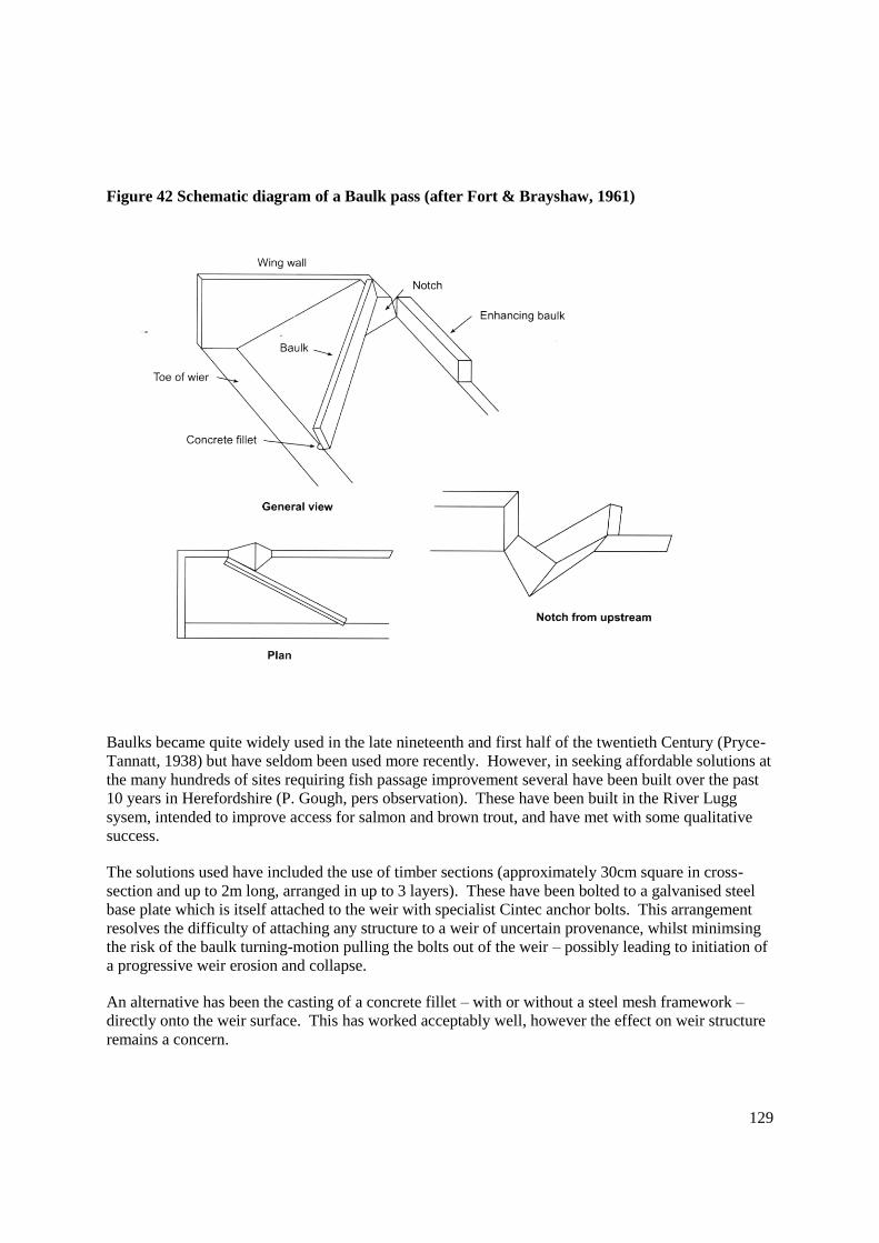
129
Figure 42 Schematic diagram of a Baulk pass (after Fort & Brayshaw, 1961)
Baulks became quite widely used in the late nineteenth and first half of the twentieth Century (Pryce-
Tannatt, 1938) but have seldom been used more recently. However, in seeking affordable solutions at
the many hundreds of sites requiring fish passage improvement several have been built over the past
10 years in Herefordshire (P. Gough, pers observation). These have been built in the River Lugg
sysem, intended to improve access for salmon and brown trout, and have met with some qualitative
success.
The solutions used have included the use of timber sections (approximately 30cm square in cross-
section and up to 2m long, arranged in up to 3 layers). These have been bolted to a galvanised steel
base plate which is itself attached to the weir with specialist Cintec anchor bolts. This arrangement
resolves the difficulty of attaching any structure to a weir of uncertain provenance, whilst minimsing
the risk of the baulk turning-motion pulling the bolts out of the weir – possibly leading to initiation of
a progressive weir erosion and collapse.
An alternative has been the casting of a concrete fillet – with or without a steel mesh framework –
directly onto the weir surface. This has worked acceptably well, however the effect on weir structure
remains a concern.

130
An alternative not yet used is the deployment of pre-cast concrete sections (perhaps some form of
kerb-stone) secured on the weir with anchor bolts. This promises to be cheaper, and when combined
with anchors designed to sheer when subjected to excessive forces during especially high flood flows
in order to prevent damaging occurring to the weir, a more sustainable solution.
Costs for each variant have been modest (£5 - 20K). Those at the higher range have been more
expensive because of the challenge of ensuring adequate fixing mechanisms. This has necessitated the
use of structural assessments, pull-tests, and a very careful specification of the licenced Cintec
anchoring system..
Although there is still a lack of information available giving guidance on the design and installation of
baulks to ensure effective operation. Some information, based largely on empirical experience, is
given by Pryce-Tannatt (1938), as follows:
Optimum head difference: ................................ c. 2m
Maximum glacis gradient: ................................ 1 in 4
Maximum length of baulk: ............................... c. 20m
Angle of baulk in relation to weir crest: ........... between 25º and 45º
Suitable Species: typically used for larger salmonids, but may be effective for some coarse species,
depending on head differences, lengths and gradients.
Strengths: cheap and easy to construct and maintain. Relatively simple to retro-fit to existing weirs.
Weaknesses: limited application for fish species. Limited range of operation. Lack of sound design
criteria.
Observations of performance of a network of nine baulks in the Lugg system, amongst other fish
passes and some partially passable structures indicates that the baulks have expanded the range of
salmon along the river. In several cases salmon and trout have been observed to use them, although
this clearly does not represent strong evidence (P.Gough, pers. observations).
Baffle systems
A variety of baffle types and configurations, constructed from a range of materials, have been used to
improve fish passage, particularly over low head difference weirs. These are designed to retain water
depths, reduce velocities and create heterogeneous flow conditions on the structure in question.
Because of the range of applications and the paucity of standard design criteria available for such
devices, it is often most practical to undertake hydraulic modelling studies to ascertain the most
effective design for the specific weir under consideration and for the species and size range of fish
involved.

131
Typically, baffle systems are located on the downstream glacis of weirs, although examples have been
described in channels set into the weir face, in drowned notches at the weir crest, or in purpose-built
channels built below the weir.
Systems have been used in Japan (Nakamura, 1995) and New Zealand (Mitchell, 1995) incorporating
the use of either natural boulders or purpose-built concrete blocks embedded in the downstream
glacis. Whilst instinct would tend to dictate that these boulders should be set randomly to increase
turbulence and reduce water velocities, trials have shown that they are most effective if arranged in
ranks in line with the water flow. These materials have also been deployed in shallow channels set
into the weir face. Again, hydraulic modelling can be used to determine the precise characteristics of
such systems, allowing for fish species and size, weir characteristics and prevailing flow regimes.
Two baffle systems have been the subject of recent development in England & Wales. The first was
the Hurn-type baffle system developed for Flat V gauging weirs, and the second was the Low Cost
Baffle solution (LCB) developed for Crump type and sloping weirs.
Hurn-type baffle system for Flat V weirs
A particular baffle system (known as the Hurn-type baffle system) was developed and installed in
England on a small, (10m wide) Flat V gauging weir in Dorset (Walters, 1996a). Hydraulic
modelling determined the configuration and location of the baffle system which was intended to allow
passage of dace of 200-300 mm length over the weir, (a burst speed of 1.5ms-1
was used as design
flow criterion) whilst still retaining its properties as a gauging structure. The device was finally
constructed using bars made of recycled plastic with dimensions of 100mm wide and 150mm high
(Walters, 1966b). Initial hydraulic trials suggest that it would restrain velocities that enable dace to
pass the structure, where previously they failed to do so. However, when used in practice at Hurn weir
trials dace seemed to be incapable of exploiting any low velocity areas created on the weir face
because the turbulence that is created on the structure at field scale appeared to confuse and
disorientate the fish and they could not discern any routes to the upstream. On the other hand, where
the system was employed at (four) sites in SE Wales in streams supporting salmonids (salmon and
brown trout) it was considered (Gough pers comm) that fish were able to exploit them (though no
definitive tagging trials have ever been completed).
In view of experience to date the system is no longer considered suitable for coarse fish, but is still
considered suitable for salmonids.
The geometric characteristics of the Hurn-type baffles on a Flat V weir are shown in Figure 43, while
a velocity profile is given in Figure 44.

132
Figure 43 Characteristics of the Hurn-type baffle system (After Walters, 1996)

133
Figure 44 Velocities on a Flat V gauging weir fitted with Hurn-type baffles
Velocities in ms-1
Example for Flow rate of 1.0 m3s-1

134
The Hurn baffle system is specific to the particular configuration of the Flat V weir in terms of weir
slopes and width. In order to apply it to other similar weirs of different widths, then the baffle
dimensions would have to be adjusted to scale. The dimensions of the baffles, slots etc are scaled
linearly, while the water velocities and discharge are scaled according to non-linear functions.
The scaling of baffles is simple since the dimensions are in linear proportion to the width of the weir,
taking the Hurn model as the starting point. For example, consider the application of baffles to a weir
of 7.62m width. Hurn Weir is 10m wide and the baffles are 0.1m wide, 0.15m high and are spaced at
0.67m apart. For the new weir, 7.62m wide, each of these dimensions requires scaling by multiplying
by 7.62/10 or 0.762. This yields baffle dimensions of 0.76m, 0.114m and 0.511m for width, height
and spacing respectively.
To calculate a water velocity relative to that shown for Hurn Weir the scale factor must first be
calculated, i.e. Hurn Weir width/new weir width. In the case of the new weir 7.62m wide, then the
ratio is 1:10/7.62 or 1:1.31. The reciprocal of the square root of this ratio must be taken to find the
velocity-scaling factor: 1/(1.310.5
) = 0.874. Thus, a velocity marked on the diagrams given in the July
1966 Supplementary Report (Walters, 1966b) for a known discharge, should be multiplied by this
velocity-scaling factor.
To calculate a discharge relative to that at Hurn Weir, an appropriate scale factor must then be
calculated. In this case, use is made of the width ratio as above, modified by raising it to the power of
5/2 and then using the reciprocal of this figure: 1/(1.315/2
) = 0.51. Therefore, a discharge of 1.00m3s
-1
at Hurn would be scaled to 0.51m3s
-1 for the new weir.
Some examples of scaling for different sites are given in Appendix IX.
When used on gauging weirs the coefficient of discharge of the Flat V weir is not to be altered by
more than 1%. Thus, the position of the top baffle should be checked. The methodology for deciding
where the most upstream baffle may be placed is described in Chapter 5 of White, Bowker &
McGahey, 2005, Flow measurement structure design to aid fish migration without compromising flow
data accuracy, Science Report SC020053/SRS.
Suitable species: only suitable for salmonids.
Head difference: generally 1m.
Gradient: 20%.
Velocities: target dependent on species but 3.0ms-1
for migratory salmonids.
Strengths: Relatively cheap, and simple to retro-fit to existing structures.
Weaknesses: gauging weirs need re-calibrating after installation, since the installation of baffles is
likely to reduce the modular operational range of the station.
It should be noted that where Hurn type baffles are fitted to existing structures there is no requirement
for formal fish pass authorisation, however the details should be made known to the NFPP for
auditing purposes. In the case of a new structure being built that incorporates this system, then the
formal authorisation process must be completed.

135
Low Cost Baffle (LCB) solution for Crump-type and sloping
weirs
A recent solution has been the result of a three year PhD study (Servais, 2006; Rhodes & Servais,
2008) in the hydraulics laboratory to find a low-cost means of retarding velocities and retaining depth
on sloping weirs in a way that is suitable for fish to pass. Without baffles water flow on a sloping weir
simply accelerates in a region of super-critical flow resulting in very high velocities and very thin
depths, before returning to sub-critical flow metres down the slope in a hydraulic jump near the
downstream water level. The high velocities and thin flow depths make it difficult or even impossible
for fish to pass.
In the idealised version (
Figure 45) the first two baffles have inverts level with the crest of the weir, the first baffle being
smaller (120mm) and the second and subsequent baffles being 200mm. Baffles down the weir slope
are placed parallel, at right angles to the flow direction, and are equally spaced down the weir at
400mm intervals. A free gap in each baffle, starting at the upstream bank, runs successively across
and down the weir forming a channel with consistent depth and low velocity. On wider weirs this
channel could form one diagonal run, but on narrower weirs the channel is reflected across the weir
forming a V-shaped run. Where the channel is reflected the slots are particularly arranged to ensure a
water jet cannot by-pass straight down to the next slot.
The design was very much aimed at coarse fish species and the slot is 250mm wide. Fish are expected
to exploit the low velocity oblique channel in low discharges. Comparison of modelled depths of flow
and water velocities suggests that the solution creates conditions that most species of fish will be able
to exploit over a wide range of flows. In high discharges it is also expected that fish might both
exploit this low velocity channel, and the retarded velocities and retained depth of water above the
baffles i.e run straight up over the baffles.
For large migratory salmonids it is proposed that the free gap be increased to 350mm, while ensuring
that the same horizontal distance is maintained between successive slots to avoid any increased
chance of water jets by-passing straight to the next slot downstream.
The design can be adapted for Crump gauging weirs, and in fact the system was developed on the
model of such a conventional Crump gauging station – see section on fish passes and gauging weirs
(page 192).
The system could be adapted and deployed on wide weirs where a single diagonal run reaches the
tailwater level by isolating the section of weir with the LCB from the rest of the structure. A
longitudinal baulk high enough to act as a side-wall and retain flow in the system to a sensible depth
(say 0.3 -0.5m above the baffles) would create a passable section of weir.
The system has yet to receive any widespread use. However, a field trial has been carried out at the
Crump gauging weir (Brimpton GS, R.Enborne) that was used as the basis for the hydraulic
modelling. Of 61 fish electrofished from reaches upstream of the weir and displaced downstream a
minimum of 36% made it back upstream, and 63% of those individuals that actually made an attempt
to move back upstream were successful. Sample size included 45 chub (23.7-51.0cms) of which 18
were successful, 9 dace (18.5-24.0cms) of which 3 were successful, and two roach (24-24.4cms) one
of which was successful. The most optimistic assessment of efficiency was for the group of chub, of
which 27 attempted the weir, putting efficiency at 67%.

136
Some of these fish moved back upstream under relatively low flows when the free gap would have
been available only, but many under higher flows when they might have used the free gap or swum
over the tops of the baffles. These trials were encouraging since the baffle system had to be
compromised form the ideal by moving it down the weir slope (as outlined below), thus a high
velocity zone still occurred between the topmost baffle and the weir crest. A trial at a non-gauging
weir site where the system has been modified for migratory salmonids as above is ongoing (first
season will be 2010).
Hydrometric trials are still onging at Brimpton, but so far the gauge with baffles has performed as
expected in relation to the discharge characteristics and is thus regarded as satisfactory in terms of
measuring flow. It has also been satisfactory in operational terms with little problem with trash or
debris being retained on the structure to interfere with gauging continuity.
Figure 45 General arrangement of the Low Cost Baffle solution at field scale, in plan and
elevation & showing cross-sectional details

137
When used on gauging weirs the coefficient of discharge of the Crump weir is not to be altered by
more than 1%. Thus, the position of the top baffle should be checked. The methodology for deciding
where the most upstream baffle may be placed is described in Chapter 5 of White, Bowker &
McGahey, 2005, Flow measurement structure design to aid fish migration without compromising flow
data accuracy, Science Report SC020053/SRS. This results in the most upstream baffle being some
distance downstream of the crest, which is likely to compromise its performance as a pass.
Suitable species: potentially might accommodate most species.
Head difference: generally 1m.
Gradient: 25%.
Velocities: target dependent on species but 3.0ms-1
for migratory salmonids and ≤ 1.5ms-1
for
coarse fish species.
Strengths: Relatively cheap, and simple to retro-fit to existing structures.
Weaknesses: gauging weirs may need some re-calibrating for higher discharges after installation,
since the installation of baffles is likely to reduce the modular operational range of the station.
Enhanced risk of gauge downtime through trash/debris collection.
Preliminary Weirs (Pre-Barrages, Check Weirs)
To effect fish passage at low head obstructions preliminary weirs (Figure 46) can often provide a low
cost but effective solution. They are placed downstream of the main obstruction in order to reduce the
head loss across it. Typically may also be located below culverts, road bridges and similar structures
to maintain passable water depths through the channel conduit. They would also be found below other
larger weirs, where they have been used to raise the water level in the weir pool to allow either
sufficient depth of water for fish to leap, or else to assist in drowning out the weir to allow fish
passage. They are commonly used in conjunction with a notch or gap in the primary structure, and
can even be used as a device to ensure proper drowning of the entrance to a formal fish pass. A
series of such weirs can be installed over a length of channel depending on the overall head difference
that is to be overcome.

138
Figure 46 Schematic plans illustrating the use of pre-barrages across the whole, or part of the
width, of a stream in front of a barrier (after Larinier, 1992a)

139
Normally of simple construction, e.g. blockstone or natural stone drilled and cemented to bedrock,
they can span the whole channel in relatively narrow streams, or else form a pool in front of the
intended area of passage in a wider structure. Generally it is best to locate them near to the banks,
where fish are most likely to be moving and to facilitate maintenance. There should be sufficient
depth of water on the crest of the structure to ensure that fish can swim over, and this will usually
mean that there is a notch or slot somewhere that will ensure this condition prevails at low river
discharges. Wherever it is expected that fish may pass, the crests of the weirs should be shaped to
ensure an adherent nappe.
The head at individual weirs should not exceed 0.3 – 0.5m for migratory salmonids 0.15-0.3m for
coarse fish, and the downstream water depth should be at least twice the head. The length of the pools
should usually be a minimum of 3m, but in practice they will often be longer because mean power
dissipation values will tend to rise rapidly with increasing river discharge.
Guidelines for the minimum length of pools and for power dissipation values are generally the same
as those for pool passes. In cases where there is a modest discharge in the facility then volumetric
power dissipation values should be 150Wm-3
for migratory salmonids, and 100Wm-3
for trout and
coarse fish at all times when they are expected to be migrating. If only a few preliminary weirs are
required for migratory salmonids then higher than normal power dissipation limits may be used for
large installations, for example where discharge is >10m3s
-1, perhaps up to 500Wm
-3.
Suitable species: any species if streaming flow, otherwise only salmonids and larger surface and mid-
water swimming coarse fish. Plunging flows are not suitable for shad, eels or benthic species of
coarse fish.
Head difference: up to maximum 0.5m for migratory salmonids, 0.30m for coarse fish, but
preferably ≤ 0.35m and ≤ 0.20m respectively.
Length: generally unconstrained except for dependence on power dissipation limits, and ensuring an
effective entrance location if the facility does not span the whole stream. It is not sensible to have
pools less than the minimum lengths quoted for pool passes.
Gradient: 10%.
Strengths: generally cheap and easy to construct and maintain.
Weaknesses: can be problematic for fish passage at low flows if not designed well.
Modifications to the Natural Bed
Fish passage can be effected at natural obstructions by a variety of pragmatic modifications,
depending on the nature of the obstruction and the species of fish involved. Notches, channels and
pools cut into bedrock can all be used to ease passage and may be deployed with a combination of
other easements (baulks, preliminary weirs, baffles). Such obstructions may even be removed
completely where circumstances and management policy allow (see Environment Agency Salmon &
Sea trout Strategy, and Brown trout & Grayling Strategy). It should be noted that such removals often
carry some risks associated with deconstruction and potential changes in water level upstream. Where

140
percussive methods are used for deconstruction care should be taken to consider the immediate
environmental impact of such methods. Design criteria are difficult to define for such modifications
and a pragmatic approach based on experience is required.
In the absence of directly applicable designs, guidance can be drawn from conventional types of fish
pass or easements. For example, minimum depth criteria can be drawn from guidance relating to
easement of fish passage at culverts and bridge footings. Guidance for pool and traverse fish passes
relating to pool dimensions, swimming depth, pool head-loss and energy dissipation can suggest if
potential modifications are likely to be effective. One often used rule of thumb is to consider the
proportion of “white water” in any plunge pools. Ideally pools should have less than 75% “white-
water” and be deep enough for fish to swim through rather than leap over any traverses or transition
points.
Suitable species: typically carried out in upland streams where salmonids are the target species.
Head difference: generally low, 1m, for any one traverse, but may be considerable overall.
Gradient: variable depends on location.
Velocities: usually within burst speed capability of the target species, but may approach maximum
swimming capability.
Strengths: cheap, and often easy to carry out. Can be unobtrusive in a natural setting.
Weaknesses: Vague design criteria. May not be effective at all flow ranges.
Rock Ramps
Rock ramps have been used extensively and relatively successfully in Britain, Europe and Australia to
provide or improve passage at obstructions of a modest height. They are perhaps specially suited to
use at vertical fixed weirs. They have the benefits of very wide species applicability, low maintenance
and high operational availability in addition to the avoidance of fish attraction problems (at full
width). With suitable design they can operate over a wide discharge range and can achieve high value
to cost ratio when species diversity is incorporated in the analysis. Ing and Gebler (2007) provides
guidelines for key rock ramp designe parameters in relation to more than 20 european fish species.
A ramp of bedrock and mixed bed material is located on the downstream side of an existing weir, to
create a semi-natural river bed of reasonable gradient (5%) to allow fish passage over a low head
(1m) structure (Figure 47 & Figure 48). Typically, the ramp covers the whole width of the river
channel - where ramps have been built over only part channel width, difficulty has been experienced
in retaining satisfactory water depths over the ramp, when water merely percolates sideways through
the material. Part width channels have also lead to difficulties in fish finding the entrance to the pass
although modifications to invert of the weir at the head of the ramp can ensure preferential flow to the
rock ramp. To ensure operation over a wide range of flows, the ramp may have one or more low
flow, dished channels. To accommodate higher heads, ramps have been constructed over a 2m head
with the incorporation of a resting pool at half height. Pool and traverse design criteria could be used
for such a resting pool. Full width rock ramps can accommodate higher head structures given suitable
space and conservative design.
Normally the ramp is constructed in a downstream to upstream direction. Care must be taken to secure
the downstream end of the ramp to prevent the toe from being removed in high flows. Similarly, it is

141
critical that any settling that may occur does not lead to a gap developing between the upper end of
the ramp and the crest of the weir. Transverse rows of large boulders may be set into the design at
regular or irregular intervals, to assist with the stability of the structure and to help retain water depths
over the ramp. It may be advisable to create notches in the weir crest or lower the crest in whole or
part to ensure that fish can negotiate the transition from the ramp over the crest. Alternatively, the
ramp can be finished at a slightly higher level than the crest, with the subsequent back-watering of
water over the crest. Simpler structures involving the random placement of coarse rock in a channel
can provide fish passage benefits but care must be taken that the slope is sufficiently low to retain the
new material under flood flow conditions.
A continuum exists between the low slope loose bed ramps to the locked in place large rock ramps at
high slope that are stabilised with deep anchors such as sheet piles. Low slope loose ramps can be
built without river diversion leading to a trade off between the size of the structure and the ease of
build (low slope). Where rock has to be anchored and accurately placed diversion of river flow is
often necessary. Some of the largest fish passage facillities in Europe are being built with significant
rock ramp components (Ing and Gebler, 2007), with some suffuciently large to be significant habitats
in their own right. In some cases it is possible to use such relatively high energy habitats to provide
rare habitat in heavily modified rivers. In particular, for rheophilic species or species that require
coarse substrate in which to spawn the riffles and pools that can be designed into large ramps may be
very important for local fish populations.
Studies in Germany (Gebler, 1998) and Australia (Harris et al, 1998), have shown that small fish and
even invertebrates are able to move upstream using rock ramps, making use of the interstitial system
between the boulders and cobbles to effect migration.

142
Figure 47 The general design layout of experimental rock-ramp fishways in New South Wales,
Australia (after Harris et al, 1998)
Figure 48 Plan view of a fish ramp in the corner of a weir on the Elz River, Germany (after
Gebler, 1998)

143
In Wales a rock ramp with a gradient approaching 10% has had some success in permitting passage of
sea trout in a naturally steep gradient river. A wide central section of a 1.5m high bed-check weir
above a new passable culvert was removed. While re-grading was planned, a modest flood event
succeeded in completing this naturally. Large rocks were added to help stabilise the resulting ramp,
which extended over some 30m at a mean slope of 9.8% (the length of stream above was already at a
steep gradient). Sea trout have subsequently spawned above this formerly impassable structure
(Armstrong, pers comm).
Typically, large rocks that are used either to stabilise the structure or retain water depth on the ramp
must be substantially embedded in the ramp. An often used rule of thumb is to embed the rocks by
two thirds, in other words for each unit of height exposed two units must be embedded. In practical
terms this can lead to rocks of substantial dimensions. It is also normal to include a wide range of rock
sizes to “lock” the substrate rock together which also tends to reduce leakage through the bed during
periods of low flow.
Where the rock ramp forms only part of the river width at an obstruction it may be necessary to
artificially concentrate the flow ejected from the ramp to encourage some species to locate the ramp.
In such cases a compromise is often required between the effectiveness of the attraction jet and the
reduction in range of species that may be able to ascend the jet.
Where a wide range of species are required to pass extra features that increase heterogeneity of water
velocity can be incorporated to aid the poor swimming species. These additional features may include
a cross slope in the ramp as well as at the entrance to the facility which introduces a range of water
depths and velocities. The lowest velocities being at the edges in the shallowest water.
Whilst most rock ramps are associated with large rocky structures, it is possible to construct rock
ramps on rivers and streams using small rocks where the slope and limited flow range allows a stable
structure to be formed. In such cases the effective slope can be reduced by the introduction of in-
stream meanders created by the formation of alternating gravel/flint bankside projections. Structures
such as these can be introduced in less than a day even using manual labour and a ready supply of
substrate. Great care must be taken regarding the range of flow and velocity likely to be experienced
as this will dictate the size of substrate required.
Suitable species: can potentially accommodate a wide range of aquatic fauna.
Head difference: normally 1m but can be used up to 2m with the use of resting pools.
Gradient: normally 1-5%.
Velocities: maximum heterogeneity desirable.
Strengths: suitable for a wide range of fish species and sizes. Relatively cheap and easy to install,
operate and maintain. Can be adapted to a wide range of flow regimes. High aesthetic value.
Weaknesses: may settle or disintegrate in high flows if not constructed robustly.

144
Sweeps
In Denmark (Hyldegaard and Peterson, 1999) a novel approach to the problems of fish passage at
existing dams has been developed, effectively combining a wide gap with a rock ramp. A large gap is
created in the dam, and then parallel vertical double-pile walls are built either side of the gap back up
through the entire impounded section of river (Figure 49) and until the head is lost over the previous
natural channel slope. This effectively creates a channel within a channel (a low level ramp and a high
level impoundment). The inner central channel (though it might also be made on one side or other of
the river) is then re-formed with a low natural gradient in a similar way to a rock ramp, using natural
materials that ensure a suitable ruggedness and heterogeneous velocity conditions. This approach has
been taken at many relatively large barriers where there was a need to retain both parts of the original
dam and the water level immediately upstream of the existing dam, for continued industrial activity.
The fishway channel is designed to give a minimum water depth of 0.2m, with maximum, mean
cross-sectional water velocities of <1ms-1
for 90% of the time during the main migration period. The
sloping bed of the sweep channel has a gradient of <10‰ (i.e. <1%). The channel can be several
hundred metres long, e.g. 350m long at Stora Dalum Paper Mill dam, Fyn County, Denmark. Sweeps
and by-pass channels are now the only fishways used in Fyn County, Denmark on the basis that they
are more efficient than other technical solutions, and also accommodate all species of fish.
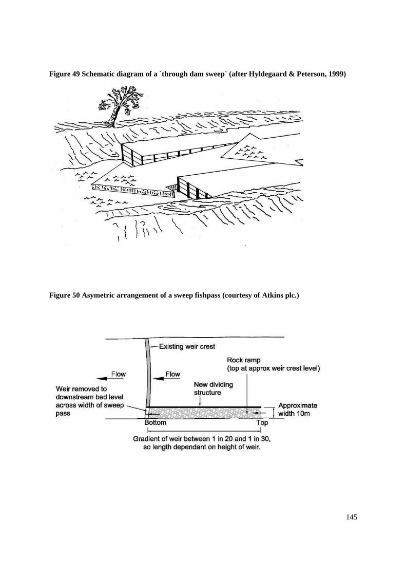
145
Figure 49 Schematic diagram of a `through dam sweep` (after Hyldegaard & Peterson, 1999)
Figure 50 Asymetric arrangement of a sweep fishpass (courtesy of Atkins plc.)

146
Suitable species: all species.
Head difference: up to several metres.
Length & Gradient: up to several hundred metres long at a 1% gradient (might be steeper where
large discharges are available).
Width: suitable to maintain the target depths and velocities specified below.
Depth & Velocity: Minimum depth of 0.2m and velocity (1.0 ms-1
during 90% of the relevant
migration period(s).
Strengths: Efficient for a wide range of species, not prone to blockage.
Weaknesses: Significant aesthetic impact, that is not necessarily pleasing.
Artificial River Channels
Artificial river channels are widely used in Europe and in North America to overcome passage
problems, frequently in relatively large rivers and at obstructions of considerable height (many
metres). A continuous riverine link is formed round the barrier using a channel that can be more or
less natural, depending on the specific site requirements. Energy is dissipated within the channel by
means of informal structures (blockstone weirs) placed at regular intervals or by the unevenness of the
channel bed, achieved using either natural materials (boulders) or purpose built blocks etc, or by
mimicking pool/riffle sequences. Such channels can have a variety of uses, not solely related to fish
passage. In some cases, the channel can be constructed to allow the spawning and subsequent
development of fish, thus creating additional habitat in a river, or for the compensation for loss of
habitat resulting from barrier construction. Channels can also be designed to accommodate
recreational activities such as canoeing.
Where the design of the channel is more formal or semi-natural, with regular cross walls creating
symmetrical pools, the structure can be designed with the normal energy dissipation characteristics
and fish swimming abilities in mind.
Where more natural channels are envisaged, relying on bed roughness to reduce water velocities,
physical modelling may be the most appropriate method of ensuring that the design achieves its
objectives. Adjustments both during and after construction may be necessary.
Near natural artificial channels should be of a more gentle gradient (usually 0.03-2.5%) and can be
made to accommodate the migration needs of most freshwater fish, both for upstream and
downstream movements. If the channel is built to mimic a pool/riffle sequence, with a heterogeneity
of flow characteristics, then a range of species not normally considered for fish passage can use the
facility eg bleak, gudgeon, bullhead, loach etc. In the case of near natural channels, it is very
important to monitor channel morphology changes after construction and make modifications if
necessary.
A useful summary of design criteria, developed from a classification of channel widths and slopes
originally proposed by Huet (1949), that can be used for planning natural type fishways is given by
Parasiewicz et al (1998). This text also provides pertinent conceptual guidelines for the design and

147
construction of this type of passage facility and is recommended as a reference source when planning
them (Table 5).
Table 5 Framework used in the initial planning phase to describe the approximate dimensions
in terms of slope, discharge and maximum mean velocities in nature like by-passes in Austria
(After Parasieewicz et al, 1998)
Parameter Upland Upland Lowland Lowland
Mean river discharge (m3s
-1) <20 20-100 <20 20-100
Bypass Discharge (m3s
-1) 0.25-1.0 1.0-5.0 0.25-1.0 1.0-5.0
Maximum pass slope (%) 0.3-2.5 0.2-1.75 0.1-0.3 0.05-0.2
Maximum mean x-section velocities (ms-1
) 0.5-1.3 0.5-1.3 0.3-0.5 0.3-0.5
Mean by-pass channel width (m) 1-5 5-25 1-5 5-25
Whilst these channels can be used to overcome fish passage problems at structures which are already
in existence, they have the disadvantage that they can often be quite long and require a relatively large
amount of land for construction. Further, it is often difficult to locate the downstream end close to the
barrier in question or to divert significant flows in to them, thus leading to difficulties in attractiveness
for upstream migrants. The latter problem may not be so significant in small rivers where a high
proportion of the river discharge can be used in the fishway.
Generally the by-pass channels can only provide suitable conditions over a limited flow range, and
thus a limited range in upstream head. If the upstream head varies greatly then it will be necessary to
have some form of formal control structure, more akin to a formal technical fish pass solution.
Suitable species: can be designed to accommodate even the poorest of swimmers.
Head difference: can be used to by-pass a wide range of heads - space is usually the limiting factor.
Gradient: 5% for low weir type fishways, 2.5% for near-natural channels.
Velocities: heterogeneous, natural stream channel velocities can be modelled in near natural channels.
Strengths: can accommodate virtually all species over a wide range of head differences. High
aesthetic, and environmental value.
Weaknesses: require a large amount of land for construction and therefore may not be cheap. Can
often be difficult to arrange to have the entrance immediately downstream of the barrier thus severely
restricting attractivity and therefore efficiency.

148
In some instance channels intended for migratory salmonids may require formal approval.
Passage in Culverts and Other River Crossings
General
Wherever there are river crossings, for whatever purpose, the best solution from the environmental
viewpoint is a clear span bridge that allows the original characteristics of the channel to be preserved.
This ensures that there is no impediment to migration. These conditions might also be achieved using,
for example, a bottomless-arch culvert of sufficient width, or an over-sized box culvert set well below
bed level (0.5m), that allows natural sediment to form the the bed of the channel.
Environment Agency Culvert Policy (March 1999) makes a presumption against the use of culverts,
since their use for any purpose causes a loss of open channel, a reduction of aquatic diversity,
impinges on river corridor migrations of many different species, and also presents a flooding risk
through blockage.,. However, culverts tend to be a cheaper option than constructing a clear span
bridge and therefore tend to be the preferred option for developers. Where their construction is
unavoidable, account needs to be taken of fish migratory requirements to ensure that the culvert does
not present an obstruction to fish migration.
Generally culvert design for fish passage does not require formal fish pass approval and should be
controlled through other appropriate legislation, principally land drainage consents. However, where
technical structures are required within the culvert barrel to ensure satisfactory conditions for passage
of migratory salmonids, then formal approval will be required in some cases.
In the past culverts, may well have been constructed which cause either delay or total exclusion of
migrating fish. The common reasons for these problems include, excessive water velocities,
inadequate depth or culvert diameter, perching of the downstream inlet, rapid change in stream
hydraulics at the upstream inlet, lack of resting places, and debris accumulations causing physical
blockage or creation of any of these factors. In such instances there are a number of structures that
can be retro-fitted to improve fish migration, provided that the reduction in channel capacity does not
pose an unacceptable increase in flood risk.
New Culverts
If, for whatever reason, it is not possible to use a clear span bridge and a culvert must be used, then
the approach should be to ensure that the channel is as close to the original stream bed in terms of
slope, bed material and wetted width, as is practicable. Only in the last resort should the environment
in the culvert be an artificial one.
The problems listed above that impede passage in many existing culverts need to be avoided.
Essentially the conditions in the culvert for successful fish passage must include adequate swimming
space, adequate depth of water, appropriate water velocity, and no physical or behavioural barriers. In
addition suitable resting areas may need to be provided below, and sometimes above the culvert.
These conditions need not exist at all times or all flows, but must prevail during times (both seasons
and flow windows) when fish are actively migrating. If the latter is not known precisely, it is
suggested that these conditions are present for river flows between Q90 and Q10.
Following an extensive review of the literature, appropriate design criteria for culverts for salmonids,
are recommended by the Scottish Executive (Anon, 2000). These criteria, with some modifications, to

149
include coarse fish, to increase minimum screen sizes, and to provide contiguous fish sizes, are
reproduced in Table 6
If a culvert is screened the minimum screen gap quoted in the table should only be used where it is
essential i.e. it should not be a presumption to use the minimum gap. Where a screen is provided to
exclude trash wider gaps than these should be employed, preferably at least 250 or 300mm. Through-
screen water velocities should not exceed the criteria applicable to the length of culvert being used,
and a margin (e.g. 25%) should be allowed for increases in the through-screen velocity caused by the
partial blockage of the screen brought about by accumulating trash.
In some cases conflict may arise between the need for screen gaps sized to allow fish passage and
those required to safely prevent unauthorised or accidental access. In this case the reader is referred to
the section entitled, Screening of Culverts and Other Openings (page 161), which describes the
approach to be taken.

150
Table 6 Design criteria for culverts to enable fish to pass (Adapted after Scottish Executive,
2000)
Parameter Notes
Coarse Fish
Roach,
Dace, Chub
etc <25cms
Brown trout
<25cms &
large coarse
fish 25-
50cms
Small Sea
trout &
brown trout
25-50cms
Large coarse
fish >50cms
Salmon &
large Sea
trout
>50cms
Maximum acceptable water
velocity through culvert and any
screen fitted (ms-1
):
a,b,c,d
Culvert Length <20m 1.1 1.25 1.6 2.5
Culvert Length 20-30m 0.8 1.0 1.5 2.0
Culvert Length >30m 0.5 0.8 1.25 1.75
Minimum Diameter of Pipes (m) 0.3 0.3 0.3 0.5
Minimum Depth of Water (m) e 0.1 0.1 0.15 0.3
Maximum water Level Drop (m) f 0.1 0.2 0.3 0.3
Trash Screen (minimum gap)(m) gh 0.10 0.10 (trout)
& 0.15 (c/f)
0.15 (trout)
& 0.15 (c/f)
0.2
Notes:
a) Mean velocity of cross-section (there will be areas of lower and higher velocity) and through any screens
fitted
b) The velocities for the shorter culverts approximate to the burst speed achievable by salmonids at 5C, and
the velocities for culverts >30m approximate to the cruising speed. For coarse fish they equate to mean
burst speed and the median cruising speed achievable at 10C.
c) These velocities should not be exceeded at any flow within the passage design flow range
d) Where screens are fitted the culvert entrance may need to be over-sized to enable the trough-screen velocity
criteria to be met, and to allow a margin for the accumulation of trash that will cause the velocities to rise
e) Minimum depth acceptable at the lower end of the passage design flow range
f) Maximum drop at either intake or outlet
g) Where occasional horizontal bars are used on vertical screens they should be spaced at least 400mm apart
h) Screens should be constructed from square, oblong, or wedge-wire section materials, not round section
materials (which more easily lead to gilled and trapped fish)

151
Many of the potential problems with culverts can be avoided by doing the following:
matching the culvert gradient to that of the existing stream. Any changes are likely to
cause unacceptable hydraulic conditions at the head or tail of the culvert. The most
common problem is at the downstream end where excessive erosion occurs, resulting
in perching of the culvert.
drowning the downstream end of the culvert to a depth of at least 0.15-0.30m.
providing a resting pool of sufficient size and depth immediately downstream of the
culvert. Sometimes one may also be required upstream as well. The minimum depth
should be 30cms for trout and coarse fish, and 45cms for salmon. An area of deeper
water with adequate cover for cover and resting should also be included.
aligning the culvert with the water course, i.e. no immediate change in direction at the
head or tail of the structure. This minimises the length of culvert and provides a more
stable hydraulic regime at inlet and outlet. It does not necessarily prevent moving the
watercourse.
ensuring that the approach conditions are within the cruising, i.e.sustained, swimming
speed of the fish
ensuring that if the use of trash screens cannot be avoided then they have adequate
free gap for fish to pass unimpeded (see section on debris protection).
avoiding sharp light/dark interfaces at the culvert entrance and exit. Fish can be
reluctant to pass a sudden change, and this can be avoided, for example, by the
judicious planting of vegetation.
providing at least one barrel at a low enough level to permit passage at low flow
where multiple -barrel culverts are used.
using culverts with a high roughness coefficient to encourage boundary layer effects
Where culverts are used there are various configurations (Figure 51) that may be considered, in order
of preference for fish passage these are:
bottomless-arch culvert retaining the natural stream bed;
culvert with a depressed invert to permit natural stream-bed materials to lie on the
bed and sufficient depth of water in which fish can swim etc;
provision of a low flow channel within the barrel and;
provision of baffles within the culvert.
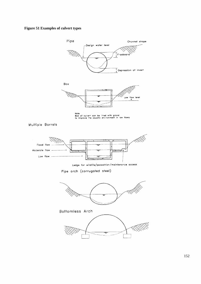
152
Figure 51 Examples of culvert types

153
It is possible that appropriate conditions may result simply from design considerations for flood flow,
however it is far more likely that the culvert will need to be over-sized.
Existing Culverts
In the case of existing culverts where there are problems these can generally be ameliorated by using
the combined effects of increased water depth and reduced water velocity. This is achieved by
increasing roughness, in the form of some type of baffle or other structure, or else by back-watering
the culvert using a pre-barrage, or by a combination of these. Since all of these will reduce, sometimes
very dramatically, the discharge capacity of the culvert a very careful consideration of the risks of
doing so is required. Where it is intended to retro-fit baffles to a culvert (s) the flood defence impacts
must be assessed and any works agreed with and consented by the relevant Authority (usually Flood
& Coastal Risk Management, FCRM, Environment Agency).
In designing baffles for a culvert a distinction should be drawn between baffles designed to increase
roughness and dissipate energy continuously, and weirs that dissipate energy in a concentrated area.
Baffles are relatively low and spaced closely together, with streaming flow over them and/or between
in any gaps between them where they are paired. If large enough to constitute weirs then designs
would follow the principles used in pool passes. Bates (1997) gives a succinct description of culvert
baffles, and further detailed information can be found in a series of papers by Rajaratnam and
Katopodis with others, 1988, 1989, 1990a and b, 1991.
Simple Baffles
Various simple baffle designs have been described may be applied to any of the typical culvert cross-
sections (most usually round or square). Various examples of these are shown in Figure 52 and Figure
53.
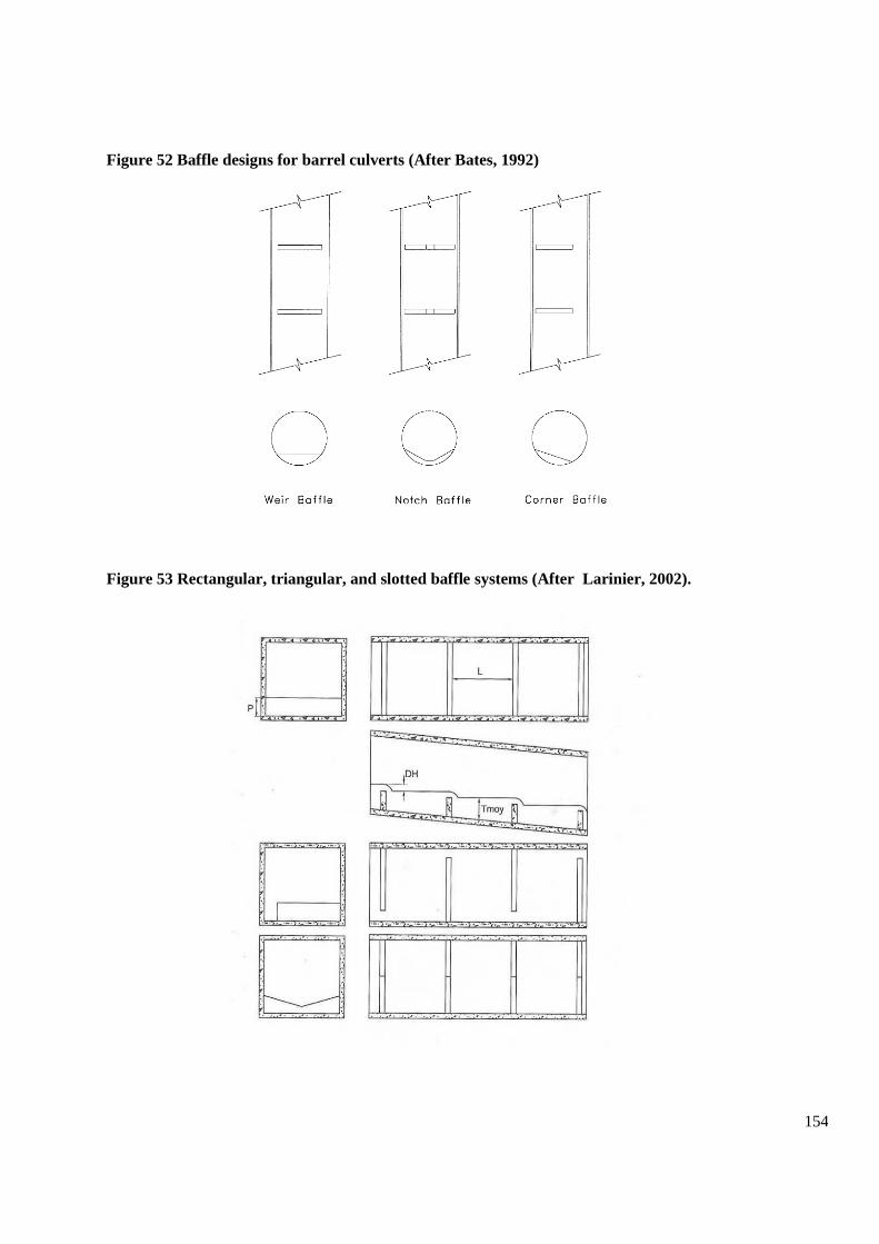
154
Figure 52 Baffle designs for barrel culverts (After Bates, 1992)
Figure 53 Rectangular, triangular, and slotted baffle systems (After Larinier, 2002).

155
Figure 54 Geometric characteristics of the off-set baffle (After McKinley & Webb, 1956)
156
Weir baffles in pipes, usually between 0.15-0.45m in height, are used to create roughness. They are
not recommended for slopes over 1%.
Corner baffles in pipes are used typically in culverts with slopes between 1-2.5%.
Notch baffles in pipes are particularly useful in wide (e.g. pipe-arch) culverts where the slope is
between 2.5-5%. The height of the central length of notch can be zero i.e. effectively two corner
baffles. Where the height of the central notch is zero and depending on the culvert dimensions, baffle
may be considerable up to a metre or more.
Horizontal baffles with notches or slots used in flat cross-section or box culverts essentially mimic
the pool pass, and ay be designed using similar criteria. Baffle heights should be sufficient to retain
the appropriate depth for the target species (see earlier guidelines Table 6) at the point immediately
downstream of each baffle. Depth of water at this point should be 2-2.5 times the head drop across the
baffle. Power dissipation in each ‘pool’ should be acceptable following the same criteria for pool
passes. The spacing of the baffles should ensure that flow does not become surging. Useful guidelines
are provided in the form of a simple formula (Larinier & Chorda (1995), Larinier (2002e) ). They
suggest that the requirements outlined mean that the height of weirs (p) will generally vary between
0.15 – 0.40m with weir spacings (L) such that the value (S x L/p) lies between 0.20 and 0.30, where S
is the slope of the structure:
0.20 ≤ (S x L/P) ≤ 0.30
Triangular- crested baffles in box culverts create more heterogeneous flow conditions than simple
horizontal baffles, providing variation in depths that fish can choose at any particular discharge. The
slopes on the sides of the triangle are generally between 1:5 to 1:7. The formula for horizontal baffles
above applies for baffle spacing.
Off-set Baffles
Another baffle system developed for use in culverts of box, circular or arch section is the off-set
system developed by McKinley & Webb (1956). It was designed for use in culverts with a slope
between 2.5-5%. These baffles are more hydraulically efficient acting as energy dissipators. Where
bed-load movement is a consideration care, should be taken not to make notch widths too small (can
occur in culverts <1.8m wide), and the spacing should ensure a minimum hydraulic drop of at least
0.06m in order to prevent gravel from inundating the baffles (Bates, 1992). Model tests by Larinier &
Chorda, 1995 showed that baffle spacing could be increased if desired to help reduce the number of
baffles required with the spacing (L) varied according to the height of the baffles (p) and the slope of
the culvert (s) as follows:
0.25 ≤ S x L/p ≤ 0.35
The off-set baffle system has been successfully employed in SW Wales (see examples below).
157
This baffle system can be adapted for shallower sloping culverts (between 1-2.5% slope) by
shortening or removing the stub baffle. In very wide culverts, >2.15m, an off-set baffle system can be
confined to one side of the structure.
Figure 54 shows the characteristics of the off-set baffle.
Some examples of baffle use in culverts
Notched baffles 0.20m high, and at 1.48m centres, were successfully deployed in one barrel of a 1.8m
diameter culvert about 30m long, 4.7% slope, at Llwydarth, Nant Sychbant, SW Wales. The other
barrel of this twin culvert had a slightly shallower gradient of 4.1% and here off-set baffles 0.3m high,
again at 1.48m centres, were deployed (see below). Baffles were fabricated from a sustainable source
of (green) oak. Despite the fact that the perching of the culverts was not addressed, migratory
salmonids passed them the first spawning season after installation.
In a typical box culvert, usually a relatively wide oblong section, a simple Chevron baffle system with
paired baffles (one each side of culvert) set facing upstream at an angle of 45° to the culvert wall and
with a free gap have been used successfully in a number of culverts in locations in SW Wales, UK
and France (pers comm., Michel Larinier). These culverts have usually had a slope < 2.5%. Baffles
have consisted various materials including concrete, but are generally fabricated from sustainable
sources of (green) oak. Spacing between baffles has taken account of the culvert slope and the need to
maintain a head drop of 0.06m (as below) between successive baffle pairs. The height of the baffles
has varied, generally between around 0.20 – 0.40m, following a maxim of preserving 0.30m depth in
the free gap between baffles for salmon and a minimum of 0.15m for sea trout (for brown trout 0.10m
would suffice). Given that many of these applications were on small tributaries or else well up
catchments, the width of free gap was designed generally to be full at river discharges around Q30. A
drowned flow equation like that for the deep slot passes was used to roughly estimate the hydraulic
condition.
At Grwylech culvert carrying a road by-pass in the River Neath catchment, concrete baffles were used
in a perched (by 0.7m) 7m wide, 80m long culvert, of 2% slope, that had been impassable for
migratory salmonids ever since its construction. The baffles were very large, 400mm high and set in
pairs at 5.20m centres with a 1.60m free gap, maintaining a depth of 0.30m at the free gap in the next
baffles upstream (see Fig nn) at around Q30 river discharge. Despite the fact that the perching was not
addressed, nor was making the flow over the downstream culvert edge adherent (usually
accomplished by using a nappe plate bolted on), and in fact, the two baffles creating a water depth and
notch (1.10m wide) at the front of the apron actually increased the hydraulic head drop, fish were
able to pass the culvert the first spawning season after installation.
Best practice dictates that the upper edges and ends of the baffles be at least chamfered so that there
are no sharp edges for fish to damage themselves, and a tendency to promote adherent and less
turbulent (aerated) flows. However, in the more rustic approaches with sustainable wooden baffles
this has not always been carried out.

158
Figure 55 Chevron culvert baffle design detail for Grwylech Culvert, Afon Grwylech, SW
Wales.
Fixing Baffles to Weirs and other Surfaces
Fixing baffles to weirs, aprons, and culvert floors requires some care since the quality and integrity of
the structure the baffles are being fixed to can be very uncertain, and is often in a poor condition sub-
surface e.g. containing voids, consisting loose material etc. Voids and loose material in the structure
being fixed to weaken the structure and inappropriate fixings used with the baffles may lead to
catastrophic failure that includes damaging the structure itself as well as losing the baffles. Each site
must be treated on its own merits, depending on the size, fabrication material, and weight of baffle
together with the severity of forces acting on it. The following approach to fixing has been developed
in South West Wales as experience has been gained providing baffle easements, using timber baffles
(green oak from sustainable sources) typically 200 – 300mm high:
159
Carry out some experimental drillings to help identify any issues e.g. voids, nature and depth
of sound material for fixing to, depth of loose material etc
For large timbers (200-300mm high), use 25mm or larger threaded high tensile bar (stainless
steel, galvanised) for fixing.
Place the pre-drilled baffle in position and drill through the baffle fixing holes and into the
accommodating surface. For a 300mm baffle a minimum of 200mm depth of fixing is
required. Where the baffle will experience significant lateral forces this should be increased.
Drill holes in the baffle should be countersunk to accommodate a top nut fixing.
Place baffle in position on a bed of proprietary bedding mortar such as ROTAFIX, especially
where the receiving surface is uneven. Threaded bar should be in location to ensure correct
positioning of baffle.
Fix the threaded bar in the receiving base hole using a proprietary anchor grout and activator
such as ZEROSET. Both bedding mortar and anchor grout will then “go-off” together. If
there are voids, fill with an injected proprietary CEMBOND product such as ROTAFIX,
allow to harden and then re-drill the fixing hole.
The top nut should then be tightened just by hand in the first instance. When the oak baffle
takes on water it will swell and an over tightened fixing has the potential to “pop” by pulling
out the fixing as the baffle increase slightly in width and height.
Once the baffle has been immersed in water and has had sufficient opportunity to take on
water (a few days) then the fixing can then be tightened with a torque wrench and any excess
bar cut above the top nut. For both security and hydrodynamics, the counter sunk voids can
then be filled with bedding mortar to form a continuous surface.
It is not recommended to use mechanical fixings such as thunder bolts or rawl plugs. These
put pressure on the accommodating surface and can cause cracking and compromise overall
integrity. This is of particular concern when the original structure is in poor condition.
For extra robustness, where required, the baffle can be haunched with bedding mortar to help
resist lateral pressure. This may affect the hydraulics so technical guidance should be sought
before this is carried out.
Increasing Bed Roughness
A simple bed-load collector has been used to increase roughness of culverts in Montana, USA. A pre-
fabricated steel frame (Figure 56) of an appropriate length is constructed to install on the channel bed.
Two or three large rocks are placed against each cross-member and used to increase roughness, thus
increasing depth and lowering velocities. The rebar loops are set at an angle upstream so that the
rocks set against them act to hold down the frame.

160
Figure 56 Detail of a Montana bed-load collector (After Belford & Gould, 1989)
Figure 57 Typical configuration of a culvert pre-barrage

161
Raising Tail-water levels
As with other obstructions a simple solution to problems is often the installation of a weir or pre-
barrage downstream of the outlet (Figure 57). This can be used to cure perching, and to improve the
water depth in the culvert. Low weirs can be constructed of stone or other materials. They should have
head drops of not more than 0.3m, and be not less than 6m apart if possible. Where necessary, notches
should be provided to ensure a sufficient width and depth in which fish can traverse the weir. Depth
below the traverse should be at least twice the head drop. The most downstream structure may benefit
from having a free gap, rather than consisting of a notch. Care should be taken to ensure that any pre-
barrage used will not result in erosion, and become perched itself. Specifically raising tail-water levels
and the conditions required in stilling basins for gauging weirs are discussed in a later section (see
Fish passage at gauging stations, page 192).
Screening of Culverts and Other Openings
Background
There is a potential for conflict between the need to maintain free passage of migrating fish in
watercourses and, where required, to exclude waterborne debris, unauthorised entry by humans, or
accidental access by humans or other mammals. In such cases careful consideration has to be given to
the design of any screens.
The Environment Agency’s approach to best practice for the design and installation of screens is
detailed in the Trash Screens: A Design and Operations Manual (R&D Publication 5A, Version 1,
2001). This document is also referred to in the Flood Defence Information Sheet No10 (Wales) which
gives guidelines for external applications. The manual provides a detailed method for carrying out a
risk assessment and making the decision whether a screen is required or not.
A screen should be designed and installed where there is a high risk of culvert blockage where that
blockage would result in serious consequences (e.g. flooding of property), and where there are no
other economic alternatives for removing the risk or minimising the risk to an acceptable level.
Additionally they should be installed where there is an unacceptable risk of a fatality occurring as a
result of unauthorised entry into the culvert. In summary, key independent reasons for screening
include the prevention of blockage, the prevention of unauthorised or accidental entry, and the
prevention of damage to the infrastructure of the culvert by debris. Clearly the risks and the need for a
screen will be generally higher in urban areas than in rural ones, and this may help reduce the
potential conflict with fish passage issues in the latter areas.
The most frequent reason for screening will be to exclude trash. This is not likely to be a particular
conflict with fish passage issues since screens with small gaps will block quickly, and this will
generally mitigate against using the size of free gaps that will create problems for migrating fish. The
conflict will arise where the screens are installed for security reasons to prevent unauthorised access.
Where security is an issue the guidelines recommended free gap in the screens is 75mm150mm.
Screens should be a minimum of 75mm because of the increased risk of blockage with smaller gaps.
Generally a gap of 150mm is regarded as sufficient to exclude children, although in areas of very high
risk it might be considered appropriate to reduce this.

162
Guidelines
Criteria to be used in designing screens for culverts, while at the same time providing for fish passage
are included in Table 6. Attention needs to be paid to the free gap dimensions, minimum depths and
maximum through-screen velocities.
Where security is not an issue and it is simply a case of protection from water-borne debris, then the
free gap used for screens should err on the generous size and not be limited to the minimum gap
specified in the table. Thus, the size of free gap employed in the screen should be 250-300mm.
Conflicting needs for screen gaps will generally arise where large migratory salmonids are present
and where the risk of unauthorised or accidental access is high. They may also occur where fish
>25cms are present and there is considered to be a need to use a screen gap <150mm because the risk
of unauthorised or accidental access is exceptionally high. These occasions should be identified as the
result of a rigorous and appropriate application of the EA Screening Guidelines. In these cases a
section of the screen adjacent to the culvert bed should be provided that meets the criteria for fish
passage. It should occupy a minimum depth of 400mm, but should extend to be near to the normal
water surface where the water is deep. The remainder of the screen may then consist of whatever
smaller gap is considered appropriate for security purposes.
Bridges
New bridges should be clear span, or else have foundations of in-river piers and abutments of
sufficient depth to avoid the problems from scour that would require aprons and weirs to be provided
(see BA 59/94 in Volume 2, Design manual for Roads and Bridges, 1993). If the latter features are
absolutely necessary then the criteria, conditions and solutions used above for culverts apply. At least
some part of the structure must provide adequate depths, and low enough velocities for fish to migrate
during the appropriate times and river discharges.
In the case of existing bridges any of the retro-fit solutions involving baffles or pre-barrages described
for culverts might be used, although in the worst cases technical fish pass solutions may be required.
Other simple designs, using baffles between 0.15-0.35m high, can be envisaged for use on bridge
aprons. Such systems are presently being used at various sites in the Regions, and an example is
shown in Figure 58.

163
Figure 58 Baffle system in use at road bridges in North East England
164
Fords
Problems with fords are the same as for culverts and bridge aprons, though often the magnitude of the
problem is less since the crossing is not so wide. A problem with inadequate depth may be resolved
by constructing a central deeper channel, or else a small conduit or culvert through the ford to act as a
low flow channel. The design criteria for culverts given above can be applied to the specification of a
conduit or culvert option. However, a draw-back of such an approach is that the resulting small
culverts are easily blocked, and this may result in excessive maintenance requirements.
Where small fish are the sole concern then a novel solution may be to construct the ford using blocks
with a gap between them that is large enough to permit fish passage (perhaps 0.15-0.2m), but small
enough to allow vehicular passage.
More radical solutions include the replacement of the ford with a free span bridge, or more often a
box culvert of large enough dimensions to ensure that culvert passage conditions as previously
outlined are met.
Tidal Flap Gates
Flap gates are normally, but not exclusively, used for the purposes of flood protection and prevention
of saltwater incursion in tidal areas. Often these purposes are mutually inclusive. Conventionally gates
are hinged at the top and hang over a conduit to act as a one-way valve. A force, i.e. a head
differential, on the upstream side will open the gate, while one on the downstream side will close it.
The stream can drain in a normal direction for part of a tidal cycle, how long depending on the level it
is set at and the tidal range. Regardless of how long it drains because of the height that it is set at, it
will only permit fish passage, if at all, over a very limited part of the tidal cycle. This is because the
gate is firmly shut over much of the tidal cycle. Even if open a lot of the time because it is set high
relative to tidal range, it will then probably be perched thus effectively preventing fish entry.
Traditionally, the gates are made of cast iron, hardwood, or some other heavy-duty material. As a
result these heavy gates have a relatively high inertia, openings are minimal, and often the gate(s)
never opens far enough to permit fish passage at all. When they are open water velocities in the
culvert behind the flap are often high, and this is exacerbated if the gate is perched.
Before attempting to improve a situation where fish access is poor, consideration has to be given to
the wider ramifications of permitting more tidal incursion and inundation. This is because it may not
be environmentally or socially acceptable for reasons not associated with fish migration. Presuming
that it is acceptable then potentially there are a number of possible solutions, or at least improvements
that can be made to enhance fish passage.
In most cases it is best to limit any improvement to just one of the control gates. If all gates were to be
improved, sharing flow between them all, then little benefit would accrue. Having one (or more)
designated gate to take most of the flow most of the time, provides the largest benefit. Often the gate
or gates designated for fish movement will be set at a lower elevation than the others.

165
Side-hung Gates
The hinges hanging the gate may be rotated from the horizontal to near the vertical, but not entirely
vertical since otherwise the weight of the gate would not help to shut it. The hinge needs to be
modified in order to cope structurally with the weight of the gate, and to physically prevent the gate
from opening so far that it cannot be shut by the downstream forces. The gate will open far more
easily, much further, and stay open longer. In addition fish can enter from the side more easily than
they can from below.
Counter-balanced & Light-weight Gates
Heavy gates can be modified by providing counter-balances on the fluvial side so that it is just closes,
but is capable of having a large opening when circumstances permit because of the reduced forces
needed to open it. Alternativly, the use of light-weight materials like plastic (GRP) or aluminium,
formed into a thin dome shape, will also permit the gate to open very much further for any given
differential head. In either case, it also means that the gate at least stays open for a longer period
during the tidal cycle.
The gate needs to open at least 0.3m for a head differential of 0.3m (Bates, 1997). The opening is
defined as the point where the gap is at its maximum i.e. usually the point directly opposite the hinge.
The theoretical benefits of using light-weight gates was clearly demonstrated by Bates by considering
the differences in hydraulic characteristics of cast iron and aluminium gates. Bates produced curves
plotting the maximum opening of cast iron and aluminium gates against head differential and
discharge (Figure 59 & Figure 60). These were derived from a theoretical static, hydraulic model that
accounted for specific weight and submergence of the gate and pressure head. They demonstrate that
for a 1.2m diameter gate, a cast iron one has no condition where it meets the above opening criteria.
In contrast, the aluminium gate is open wide. For example at a head differential of one foot and no
submergence, the aluminium gate is open over 0.75m and the cast iron gate is open about 0.15m.

166
Figure 59 Gap and flow for a 4-foot (1.2m) cast iron flap gate (After Bates, 1997)
Figure 60 Gap and flow for a 4-foot (1.2m) aluminium flap gate (After Bates, 1997)

167
An additional benefit of a light-weight gate is the resulting additional discharge capacity, that drains
the upstream impoundment more quickly thus equalising levels more swiftly. This ensures that
optimum passage conditions are achieved and maintained longer in any one tidal cycle. This helps
maximise the time available for migration.
Automated gates
Another solution is electrically powered automated sluices, with their operation linked to the tidal
cycle. The benefits of these are that the sluices can be open fully, and the time that they remain open
can be maximised. The disadvantages are that they are expensive to install, operate, and maintain. The
requirement for electrical power may also seriously compromise the feasibility of such an alternative.
Self Regulating Gates (SRT Gates)
A solution that is novel to Europe, but which has been used in the USA for 15-20 years, is the Self-
Regulating Tideway gate (SRT Gate*). The gate has many attributes including that it; requires no
electrical power supply, can be adjusted manually to operate over a specified range, and it is robust
requiring little maintenance. The gate uses a system of floats to operate it, and generally stays open
across a wide part of the tidal range. However, it is versatile enough to be set just to prevent tidal
surges or be limited to opening across only a small part of the tidal range. The very significant
advantage that this gate has over other types is that when it is open it is fully open, with the gate
floating on top of the water, thus making fish passage easy. Because it is in a free flowing state any
species of fish can pass. In many ways it is an ideal solution where there are no social or other
environmental reasons for preventing tidal incursion. Indeed, in many situations it may provide a safe
means of re-estuarising areas of habitat thus having a much wider ecological and conservation value3.
Figure 61 shows the principles of operation of the SRT Gate.
3 SRT Gates are manufactured by Waterman Industries Inc., Exeter, California, USA and can be
procured through their agents Anthony Timms, Water Control Products International, Villa Farm, Isle
Brewers, Taunton, TA3 6QL.

168
Figure 61 Operating sequence of the SRT Gate (courtesy of Waterman Industries Inc)

169
ANGUILLIFORM PASSES
General
Eels present a special case in terms of arranging free passage. Elvers and small eels, which are the
stages that it is essential to pass upstream, are very poor swimmers compared to the adult stages of
other fish that migrate upstream. Eels are not capable of jumping. While elvers can be good climbers
in appropriate circumstances, once a vertical barriers is greater than the equivalent of 50-60% of their
body length then it becomes impassable (Knights & White, 1998). Eels, especially females, can
actively migrate for a number of years during which they can occupy a considerable range in size
between 10cm to >50cm.
Because of their morphology it can probably be expected that the larger eels are adept at using lower
water velocity areas associated with boundary layers or turbulence in order to progress. As such it is
likely that fish over about 30cm are capable of using some types of conventional type fishways
provided that they do not have to jump. For example, larger eel have sometimes been monitored
successfully negotiating Larinier Super-active baffle passes. However, recent observations (Andy
Don, pers comm.) of migrating eels on the River Parrett in SW England have demonstrated quite
clearly that, given the choice of a conventional Larinier pass and a bristle ramp, all sizes of eel (10 –
50cms) almost exclusively chose the ramp. It is therefore suggested that separate fishway should
therefore be provided for eels in all circumstances where their passage is a requirement.
In the recent past two principle types of passage facility have been provided for elvers and small eels
– open or closed channel (media occupying part or the whole of the channel respectively). Both types
rely on providing a wetted medium (e.g bristles, brushes, bosses), which the eels can readily gain
purchase and wriggle through. The pass need only be provided with a very small flow of water of
sufficient volume to keep the medium well wetted – for example, recent evidence is that for pump fed
facilities a flow of only 0.5ls-1
is sufficient for effective passage. It can be beneficial to provide an
additional attraction flow at the downstream entrance. An attraction flow may be available because
the eel pass is located adjacent to a facility for other species, or else separate arrangements may be
made to inject additional flow at a low velocity near the pass entrance, or else sprayed on to the water
surface near the entrance.
The downstream entrance should be located in an area where eels are observed to congregate. This
will usually be in an area where there is a positive but weak and low velocity flow away from the
obstruction, not an area where velocity is high. The upstream exit from the pass must be sufficiently
far upstream and preferably in a low velocity zone in order to avoid migrating fish being washed back
downstream. It is essential to extend the pass, or at least the media used in the pass, extend down to
the upstream and downstream river beds.
Careful consideration should be given to screening the upstream entrance to help avoid blockages
from accumulating debris, and also to providing access points to facilitate regular maintenance of the
medium in the pass. Consideration should also be given to covering the pass to prevent predation on
the fish using it e.g. from piscivorous birds, rodents such as rats etc, and sometimes to shading it to
prevent either elevated temperatures in, or drying of, the facility.
Considerable progress on the design of eel passes has been made in the last twenty years. Many
configurations of pass have been used over this time with some success, and several examples are
given by Knight & White (1998), see Figure 62. Others are given by Dahl (1991), and by Porcher
(1992). More recently a world-wide review of best practices was carried out by Solomon & Beach1

170
(2004), and this was condensed in to a Manual for provision of upstream migration for Eel & Elver
(Solomon & Beach2, 2004). Since then the Environment Agency has recently held an international
workshop (October 2009) to draw together more recent experiences, and is presently engaged in
further updating the manual, including describing some standardised designs of pass. Most eel passes
are likely to feature bristle type media with either a gravity fed or pumped water supply. However,
some other types of media such as ABS plastic bosses (material Anguillette, Larinier pers comm.)
have also been developed and are in use in France and England.
The bristle ramp eel passes described in the manual can be built at modest cost although these are
generally made of materials and in configurations that are less permanent (more at risk from flooding
etc). The small flows required to operate pump fed passes has led to the development of systems that
can be sustained by renewable energy sources such as solar and wind power (see updated manual for
further information). All eel passes require regular maintenance because of the risks of blocking from
waterborne debris.
In any one location it should be borne in mind that many different sizes of eel may want to actively
migrate, typically any fish from 100 – 400 or 500mm. Typically maximum migration will occur on
low flows, and designs of pass should operate over a river exceedance discharge between say Q99 and
Q70.

171
Figure 62 Various configurations of eel pass (after Knights & White, 1998)

172
Closed type eel passes
In a closed type of pass, typically a pipe or trough of 10-25cm diameter or width, but sometimes a
wire cage (Dahl, 1991), a medium such as rolled geotextile or horticultural mesh (20mm) mesh, or
bottle-brushes, is provided that fills the channel and through which is passed a small volume (several
ls-1
) of water is passed. The Danes (Dahl, 1991) recommend Enkamat type 7020 as a particularly
suitable medium and this has received much use. There have been concerns expreseed recently that
geotextile type materials they are too aggressive, and although eels easily pass they lose a great deal
of mucus in the process and this may reduce their survival (Larinier, pers comm). For this reason, this
type of media is generally no longer favoured.
The entrance of these facilities is placed tight against the foot of the dam or obstruction and extends
very closely to the bed of the watercourse. Several entrances may be made into the conduit at different
levels below the downstream water surface. The conduit may be fixed at angles up to 90, i.e. vertical,
but shallower angles (15-30) are probably preferable to ease the climb. Several lengths of conduit
may be used to overcome very high obstacles. In such cases it is probably sensible to provide resting
areas every 2-3m of height.
These types of facility can can be easily made to follow the contours of low obstructions. It is
important to ensure that the medium is extended to the upstream and downstream river-bed, and that it
remains wetted throughout its entire length.
A major difficulty with closed type facilities, where the media fills the channel, is that they are easily
clogged with debris and are very difficult to access for maintenance.
Head difference: there is little data to go on, but it is suggested up to 2-3m per flight of pass.
Length: probably not more than 4-5m per flight before a rest pool.
Gradient: up to 90 but preferably 15-30.
Velocities: <0.2ms-1
.
Strengths: Well tried, relatively cheap to construct, fish safe from predation.
Weaknesses: Very prone to blockage and require very regular maintenance, can be prone to flood
damage.
Open type eel passes
In open types of eel pass a ramp covered in a medium similar to those mentioned above, but more
typically now bristles, is provided for eels to wriggle through or over (Figure 63 & 55). Other types of
media involving various configurations of different types of material, but more usually plastic based,
have also been found to be successful (see manual referred to above).
Ramps may be 0.2-1.0m wide and have a gradient between 5-45% (typically 20-30%). Bristle type
substrates consist of tufts of bristles that are spaced apart at distances suitable to meet the size of
migrant expected. For elvers and small eels up to 20cm in length spacing is 14mm apart, and for eels
>20cm spacing is 21mm apart. Often a ramp will have a strip of each (spacing) of materials side by
side. Typically the brush substrate comprises 1mm thick, 40-70mm long polyester bristles mounted in

173
tufts in 5mm holes on 1m long boards, often made of polypropylene (see Figure 64). Other boss type
materials include Akwadrain, Anguillette etc (see Figure 64).
Generally, the ramp will be self-contained and installed as a retro-fit in some form of plastic or metal
trough that is provided with a hinged lid to provide both easy access for maintenance and protection
from predators.
In order to provide for some limited range in head water level in gravity fed facilities the ramp can be
graded laterally, or else several units may be fitted side by side at different levels (see inset Figure
63).
There has been limited evidence from video monitoring that some minor species including Bullhead
and Stoneloach can use thse types of passes (Andy Don, pers com). Despite that fact that there is no
known evidence, it also seems likely that Brook lamprey may be able to exploit tem through either
thigmotropic behaviour or the potential to us their suckers.

174
Figure 63 Schematic plan of a fishway for elvers and small eels (after Porcher,1992)
Figure 64 Typical specification of brush boards for eel passes
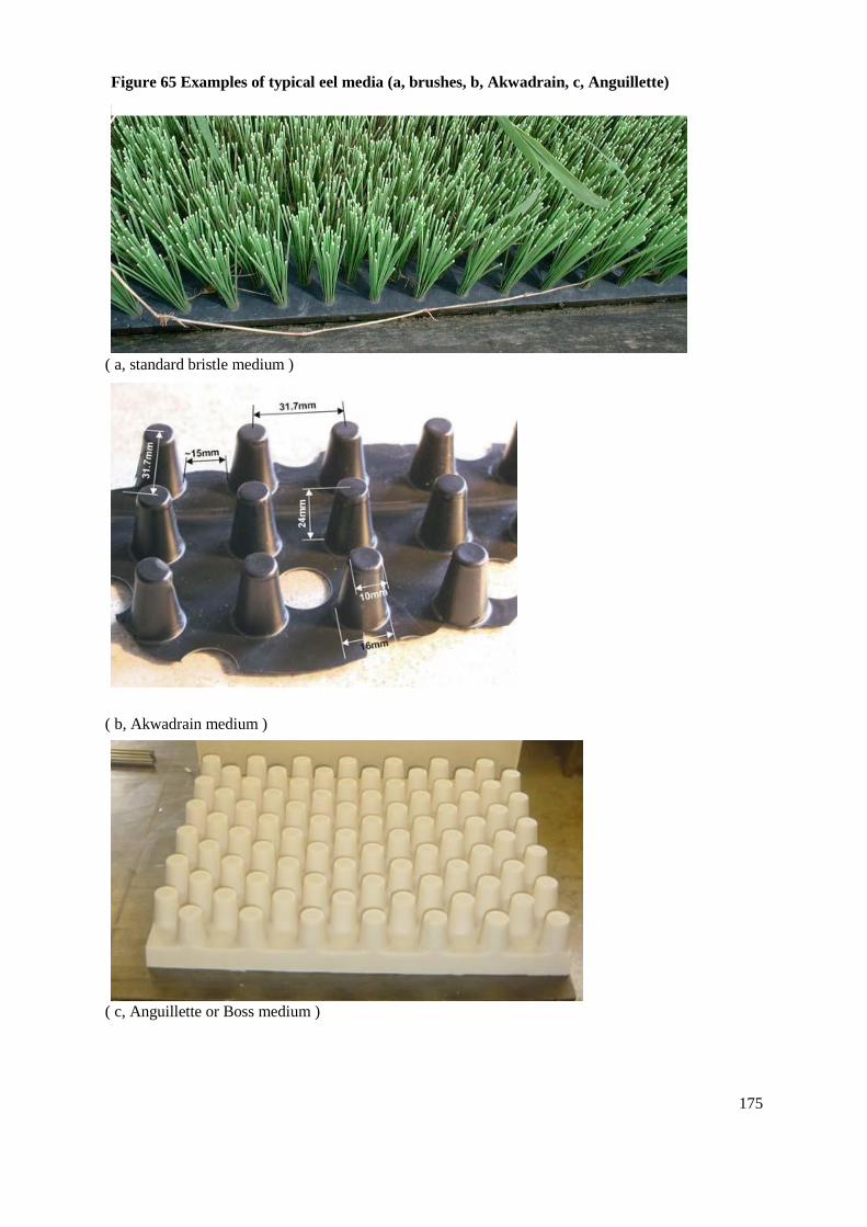
175
( a, standard bristle medium )
( b, Akwadrain medium )
( c, Anguillette or Boss medium )
Figure 65 Examples of typical eel media (a, brushes, b, Akwadrain, c, Anguillette)
176
Head difference: there is little data to go on, but it is suggested up to 2-3m per flight of pass.
Length: several metres depending on slope.
Gradient: 5-45%, preferably <30%.
Velocities: <0.2ms-1
in area of passage.
Strengths: Well tried, relatively cheap to construct especially standardised retro-fit trough units, fish
safe from predation.Require small flows and/or can cope with some variation in water level, known to
work well. Can often be de-mounted. May pass some minor fish species such as bullhead, stoneloach,
and brook lamprey.
Weaknesses: Require regular maintenance.
Monitoring
When monitoring is required it is usual to be employing pump fed facilities and to facilitate trapping
by raising the exit of the pass well above the obstruction, and then washing migrants down into a
collection chamber. In this case the pumped supply of water is necessary to both collect migrants and
to provide flow in the pass itself (see Figure 66).

177
Figure 66 Typical configuration of a pass and trap for elvers and young eels (After Porcher,
1992)

178
Lamprey Passage
Like eels the lampreys (Sea, River, & Brook) present a very specialised case when considering
passage arrangements. Unlike eel, they probably do not necessarily require a totally separate facility
to achieve acceptable rates of passage efficiency, but rather can be passed in many of the more
conventional fish pass types – provided that they are adapted to suit the very specific capabilities and
behaviours exhibited by lamprey. However, because of their very specialist skills in surmounting
obstructions separate facilities for lampreys can also be considered. Indeed specific facilities are
currently being researched and developed in the Columbia River basin to compliment passage in the
existing fish pass facilities.
Sea lamprey can attain a size over one metre in length, and for an aguilliform can achieve a
surprisingly high turn of speed - having a reported maximum swimming speed of 3.9ms-1
that can be
maintained for a few seconds – and also appear to recocver relatively quickly from their exertions.
They migrate into rivers form about February onwards, but mostly in the spring and early summer
upto early July when they spawn and then die. River lampreys migrate much later in the autumn and
winter, and are smaller, perhaps attaining 50-60cms maximum, and maximum swimming speeds and
endurance are likely to be around half that of sea lamprey. Both species are negatively photactic,
migrating at night to begin with (probably to help avoid predators) but also migrating during the day
later on in the run when their eye sight is failing because of on-coming senescence. They are likely to
be migrating in the higher range of the hydrograph, sea lamprey most likely around Q50 to Q20
experienced in spring, and the upper range perhaps Q30 to low flood flows for river lamprey. Like
migratory salmonids they do not feed in freshwater, and generally will spawn in the middle reaches of
larger rivers and their lower tributaries.
Lampreys appear to be attracted by high velocities, while on the other hand can be obstructed by high
velocities and turbulence. Outside of providing suitable low velocities the key to providing effective
and efficient passage robaly lies in exploiting the peculiar ability of lampreys to use their mouth parts
to create and control suction (Adams & Reinhardt, 2008). Lampreys can attach to suitably smooth
substrates and then use an active creeping behaviour where they release, or artially release with
areduced vacuum – burst swim – re-attach & rest before making another attempt to progress. In this
way they are able to exploit their maximum speed to make short progressive burst of progress, rather
than a more limited burst speed that has to be maintained for seconds at a time to pass an obstruction.
Pacific sea lampreys (Petromyzon tridentate) are even capable of climbing smooth vertical surfaces
with a very thin skim of high velocity flow (Moser, pers com). While this same behaviour has not yet
been demonstrated in Atlantic sea lamprey (Petromyzon marinus) it seems very likely that they must
have learnt the same behavioural tricks, and anyway they certainly exhibit the same traits of
exploiting their sucker to enhance the ability to locomote in high velocity zones.
There appears to be conflicting evidence about the ability of lampreys to pass various types of pass,
but this is probably due to the very specific features of a specific site in terms of velocities and the
availability and continuity of areas of smooth substrate where lampreys can successfully attach
themselves to aid progress. Lampreys attained unexpectedly high passage rates in Vertical Slot passes
on the Columbia River, USA, wher velocities exceeded 2.4ms-1
. Passage rates of 38-82% were
achieved in Bonnevile and Dalles dams, although in three passes now including John Day Dam
overall passage rate was only 3% (Moser et al, 2002). At smaller Vertical Slot passes in the Great
Lakes system, Cananda passage rates up to 100% were reported (O’Connor et al, 2003, 2004). Despite
not being ken on turbulence Pacific lampreys were found to pass Alaskan A Denils with slopes of
23% to near 29%, lengths of 8 - 20m and flows around 0.16m3s
-1 i.e modest depth (Slatick & Basham,
1985). Sea lampreys are known to pass some Plane Baffle (PB) Denils with video of fish passing a PB
Denil on U-tube in Ireland and fish monitored passing Stamford Bridge and the Tees Barrage Denils
in the UK for example. On the other hand, while making some progress through the Isohaara

179
combined Vertical Slot and Denil pass, river lamprey could not manage the whole fishway even
apparently with modifications designed to help (Laine et al, 1998).
Apart from using specific passes for lamprey, designed along the lines of those currently being
developed in the Columbia River basin using sloping stainless steel chutes with a skim of water and
transitional facilities of a vertical steel plate on which the ramp sits to aid location and entry to the
pass, the key to improving lamprey passage is to adapt existing facilities. This can be done by
providing smooth, preferably stainless steel plate, surfaces for the lampreys to grip and ensuring that
those surfaces have rounded or shallow angle surfaces at notches, slots, downstream and upstream
transition areas so that fish can progress to areas where they can safely detach once attached in the
first place. So the lateral urface of a notch in a Pool & Traverse pass would be rounded on the
upstream and downstream face, the vertical side-walls of a Vertical Slot pass will have a rounded
cross-section rather than sharp edges, a Crump Gauging Weir or sloping V-shaped weir would have a
stainless steel plate at one side against a wall (low velocity zone) leading from the river bed
downstream to the river bed upstream, and so on. And in any fishway, clearly, thought has to be given
to the continuity of arrangements to facilitate passage throughout the length of the pass.
Even less is known about the ecology and ability of Brook Lamprey in terms of migration. While it is
much smaller, up to may be 15cms, there seems no reason why it too might exploit its sucker. Also
like other anguilliforms it may exploit thigmotropism, so for example, it might be expected to be ale
to exploit bristle ramp fish passes provided for eels and elvers?

180
ADDITIONAL FACILITIES
Resting facilities
It should be recognised that fishways can often represent a physical challenge to ascending fish in
terms of endurance. Therefore flights of baffle fishways, or in some circumstances sequences of
pools, cannot be extended indefinitely without providing suitable areas where fish can take a rest
between exertions.
Where resting pools are required fish must be able to reside in areas of low turbulence and aeration.
The resting pools must have sufficient length and volume to dissipate the kinetic energy of the water
entering the pool before it enters the next flight or pool. The presence of residual turbulence, energy,
or currents carried over to the next downstream flight or pool will adversely affect the hydraulic
performance of the fishway thereafter. Care should be taken to ensure that exit flows from the
upstream pool or baffle flight do not strike an opposite wall with undue force, since this will generate
conditions that are uncomfortable or impossible, for fish to rest in. In addition it is useful to round the
corners of the rest pools to help prevent the formation of vertical currents that can encourage fish to
jump out of the fishway.
Power dissipation values in resting pools should be more conservative than the values used for the
standard pools in pool passes (page 62), the lower end of the range 100-150Wm-3
for migratory
salmonids and shad, and 50-100Wm-3
for other species. In general, while resting pools tend to be
larger and to have modest power dissipation values some care may be needed not to over-size them
when sedimentation may prove to be a problem (because of insufficient turbulence).
In pool passes the power dissipation values are calculated in the normal way. In order to calculate the
energy input from a length of baffle pass, an approximation to the difference in head in the energy
dissipation equation can be made from the average velocity as follows:
DHEquiv = V2 / 2g
Where:
DHEquiv = equivalent difference in head (m)
V = the estimated average exit velocity (ms-1
)
g = gravitational acceleration (9.81ms-1
)
Since this is only an approximation it may be sensible to allow a margin for error of up to 50% for
Plane Baffle passes and 25% for Alaskan A and Super-active Baffle passes (Larinier, pers comm).
The minimum length of pool for large migratory salmonids should be 3m, but may be less, say 2.5m
for sea trout and smaller still for other species. A good guide is that the pool should be at least three
times the length of the largest fish expected to be using it. Pool depths should not generally be less
than 1.0-1.5m. While pools must not be too shallow, it should also be borne in mind that over-
deepening them can encourage fish to rest indefinitely, thus delaying migration or making the fish
vulnerable to predation or poaching. Pool widths may vary, usually being equal to or greater than 2m

181
for pool passes, greater than twice the width of a plane baffle pass, and equal to or greater than the
width of a Larinier Super-active or Alaskan A baffle pass. Within these guidelines the pool
dimensions are adjusted to provide a suitable volume to achieve the desired dissipation value for the
species concerned.
In the case of baffle fishways resting pools should be provided every 1.8-2.4m (10-12m run) of fall in
head for large migratory salmonids (>0.6m long), and every 1.2-1.5m of fall in head (6-8m run) for
small salmonids (<0.6m) and for coarse fish. Resting pools must also be placed at any changes in
direction of the fishway. In the circumstances where a baffle pass changes direction, the wall(s)
opposite to the exit from any flight(s) should be at least 3m away.
With pool type passes resting pools should be provided at changes in direction of the axis of the
fishway. A deeper resting pool is often an advantage because it provides more cover for resting fish
and provides less opportunity for illegal fishing.
Protection from Debris
The need for protection from trash at any one site is clearly dependent upon the nature of the water
course and the type and quantity of debris which it carries, particularly during the migration period(s).
It is also dependent upon the type of pass since some are more inclined to block than others. Some
form of protection is always to be recommended for side or side and bottom baffled fishways which
block easily, however some pool type passes and particularly the bottom-baffle-only type fishway
may be considerably less vulnerable and not require protection at all. If there is any doubt a
protective device should be fitted.
Protection may take many forms including floating booms, screens with bars (minimum free gap
200mm, preferably spaced 250 - 300mm apart to allow passage of salmon), solid surface deflectors,
rows of rails or piles upstream of the facility, or combinations of these.
Bar screens should be designed in such a way that the velocity through them does not exceed 0.3-
0.4ms-1
to avoid clogging quickly. If vertical bars are used then any additional horizontal bars for
strengthening the screen should be at least 500mm apart. Solid screens should be designed in such a
way that velocities under or around them do not increase to values in excess of that entering the pass
(ie. cause no head drop across them nor associated acceleration of flow). Apart from potentially
interfering with the ability of fish to exit the pass, accelerating flow under shields may draw debris
collected on or near the suface underneath and in to the pass. Screens or shields should also be
sufficiently far away from the exit of the pass so as not to interfere with fish leaving it, at least 1.5-
2.0m away from the last traverse or most upstream baffle. Where surface mounted a deflector or trash
screen should have a minimum gap underneath of 40cm. Positioning of the screen should take account
of flow patterns in the vicinity to enable debris to wash away rather than back into the fishway during
cleaning. Careful consideration should also be given to access arrangements for the maintenance
operations.
The lateral siting of fish pass exits is recommended (Larinier, 1992c), since this encourages trash to
by-pass the entrance and also helps ensure that it is washed away downstream during the cleaning
process. Examples of laterally sited exits are shown in Figure 67. Note that the exit must not be sited
in any zone where a re-circulation eddy is formed, and any exit but especially a downstream facing
one, must have a flow away from it and over the weir or obstruction sufficient to carry debris away.
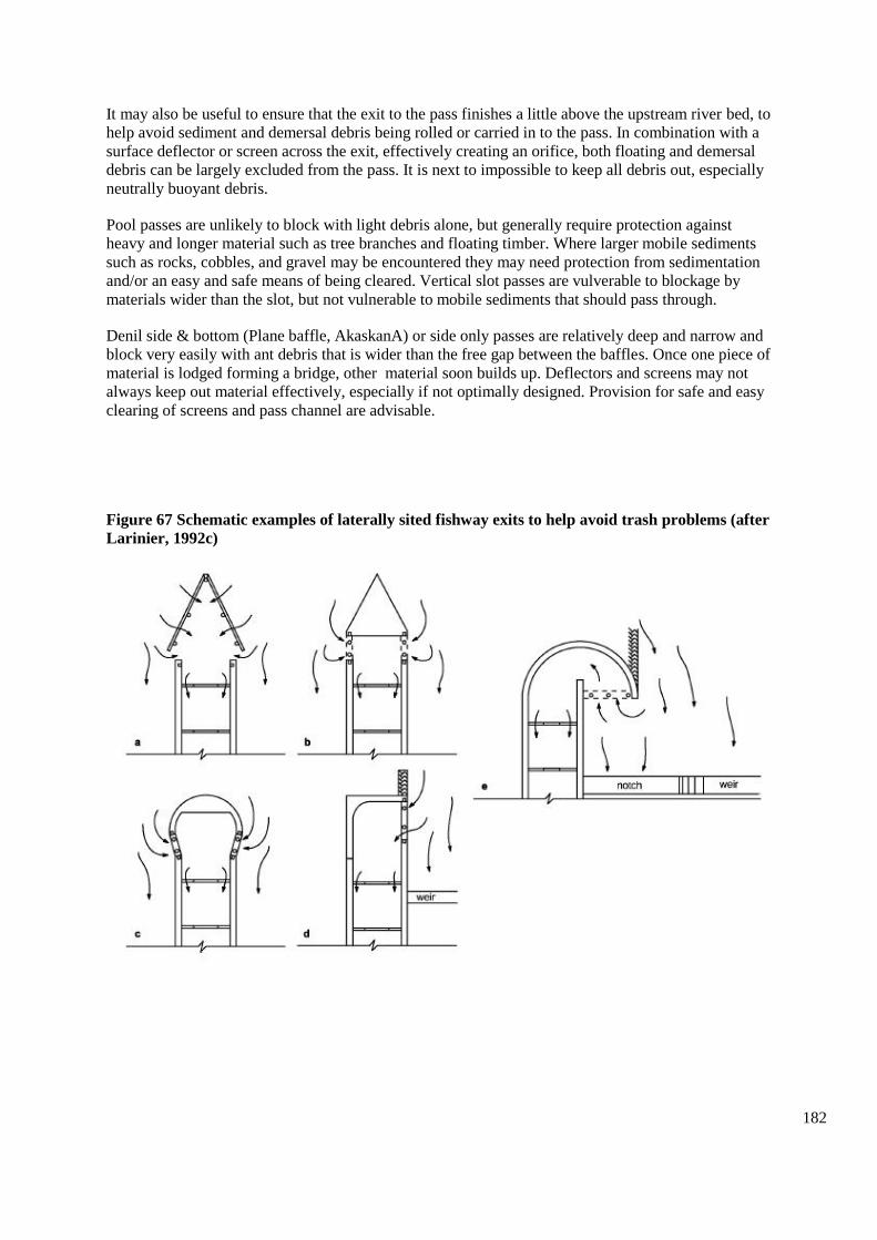
182
It may also be useful to ensure that the exit to the pass finishes a little above the upstream river bed, to
help avoid sediment and demersal debris being rolled or carried in to the pass. In combination with a
surface deflector or screen across the exit, effectively creating an orifice, both floating and demersal
debris can be largely excluded from the pass. It is next to impossible to keep all debris out, especially
neutrally buoyant debris.
Pool passes are unlikely to block with light debris alone, but generally require protection against
heavy and longer material such as tree branches and floating timber. Where larger mobile sediments
such as rocks, cobbles, and gravel may be encountered they may need protection from sedimentation
and/or an easy and safe means of being cleared. Vertical slot passes are vulverable to blockage by
materials wider than the slot, but not vulnerable to mobile sediments that should pass through.
Denil side & bottom (Plane baffle, AkaskanA) or side only passes are relatively deep and narrow and
block very easily with ant debris that is wider than the free gap between the baffles. Once one piece of
material is lodged forming a bridge, other material soon builds up. Deflectors and screens may not
always keep out material effectively, especially if not optimally designed. Provision for safe and easy
clearing of screens and pass channel are advisable.
Figure 67 Schematic examples of laterally sited fishway exits to help avoid trash problems (after
Larinier, 1992c)

183
Bottom baffle passes such as Lariniers and baffle easements are generally wide in nature with up-
welling and turbulent currents that carry material through and reduce the risk of blockage. The
roughness reated by the baffles can nevertheless catch heavy sediments (rocks & cobbles) and large
angular materials such as tree branches and trunks. Defelectors that will divert such debris are
advantageous.
A useful review of trash accumulation and ways to miminise it at fish passes is given by White,
Bowker & McGahey, 2005 (Chapter 3, Flow Measurement structure design to ai d fish migration
without compromising flow data accuracy).Completely effective trash protection is virtually
impossible to achieve. In order to facilitate easy and cost-effective structural (infrequent) and
operational (frequent) maintenance, careful consideration should be given to fitting a penstock, or
some other means of shutting-off the flow, at the head of the pass. The minimum provision should be
stop log slots.
It may also be worth considering remote surveillance to detect problems with trash, or poaching, and
to reduce the operational necessity to make overly frequent visits to the site. See section on Remote
Surveillance (page 228).
Lighting
Where possible the best situation for a fishway is to be in the open and subject to natural lighting
conditions. Where this is not possible and the pass has to be covered, or else lies within a structure,
then some consideration needs to be given to lighting conditions.
There is conflicting evidence about the effects of light levels on passage. Salmonids are known to use
fishways in both light and dark conditions. A recent study of the migration of salmon past thirty one
obstructions on the Pau River in France (Chanseau et al, 1999) showed that nearly 86% of passage at
obstacles took place during daylight, and that only natural by-pass channels enabled a significant
proportion of migrants to pass at night. Fish approaching the hydro-electric dam at Baights on the Pau
River (Chanseau & Larinier, 1999) mainly did so at dawn, and fish rarely stayed in the immediate
vicinity for more than an hour.
On the other hand shad will definitely not move through a fishway in darkness. They require strong
visual clues, not least of which is other shad since their behaviour is very much to move in shoals. A
shad fishway must therefore be illuminated, preferably with natural light.
Both adult and juvenile (i.e. smolts) salmonids are very reluctant to cross a sudden transition between
light and dark. A gradual transition between light and dark can be provided by using artificial lighting
inside the tunnel or fishway entrance, or perhaps by creating a natural light gradient through the
prudent use of vegetation at the entrance or exit.
Should there be any problem with fish being reluctant to move through a fishway, then lighting may
provide a solution.
Where lighting is used it will need to meet appropriate electrical safety standards. This will impose
maintenance and monitoring costs in addition to the normal operating costs for power.

184
Auxiliary Flow
Where it is necessary to provide auxiliary attraction flow then it should be injected at low velocity,
<0.30-0.40 ms-1
, into the downstream section of the pass, or at the entrance itself. Power must be
dissipated and aeration removed before it is fed into the pass or entrance pool. Usually this is
accommodated in a separate pool (power dissipation 1000-1500Wm-3
) or an area behind the screens
that are used to guide the flow gently into the pass. The injection of the auxilliary flow can take place
from the bed of the pass, but more likely will be from the side because the former is more liable to
create maintenance problems from clogging with debris.
The gaps between the bars of the injection screen must be small enough to prevent passage or
impingement of the fish using the pass. Larinier (1992c) suggests 25-35mm for fish >30cms, 20-
25mm for trout, 25mm for lampreys and 5mm for eels. The screens may be used to help guide fish to
the pass entrance, or else to the next traverse.
Maintenance of these screens is highly demanding, and their use would normally be avoided at remote
sites. Mounting short widths of screen on vertical pivots can be a benefit since, they can then be
cleaned by turning them through near 180, effectively using the reversal of water current to wash the
debris from the screen.
Traps
Trapping fish at the exit of a fish pass has been carried out at many sites throughout the world. At
such sites fish ascending the pass enter a screened and confined space from which it is difficult to
escape. The entry route to the trapping area generally consists of an in-scale or funnel formed from
metal mesh or bars.
The advantages of including a trap in a fish pass development are that the installation costs are often
low if incorporated at the design stage, and that a high level of monitoring of the fish using the pass
can be achieved including counting, species identification, sexing, measuring, marking & tagging,
checking for marks & tags etc. With very careful configuration of the trapping facility many of these
tasks may be achieved by direct observation without even handling the fish.
The disadvantages of using traps in a pass include the potential interference and reduction in fish
passage efficiency, high labour costs of maintenance, and the risk of injury to fish.
There are many examples of both good and bad design of traps associated with fish passes. Well-
designed trapping areas need to be comfortable for fish to remain in, otherwise they are likely to
damage themselves trying to escape. They will generally have a generous volume, good exchange of
water with no areas of stagnation, and have low levels of light intensity being well shaded and
protected from bright sources of illumination whether natural or artificial. Water velocities must be
well within the cruising speed of the target species, and this will usually be in the order of 0.3ms-1
.
Power dissipation values will be low, certainly 100 Wm-3
.
Well designed traps also need to be comfortable for operators to work in so that fish can be easily and
safely handled. Safe and easy access to enable equipment to be taken in and out is essential. Where
work is required at night then adequate lighting arrangments are clearly required, and preferably ones
that will not disturb migrating fish nearby.

185
The conditions for capturing, handling, and transferring fish during processing need to be well
designed to minimise stress and ensure efficient and rapid processing. Processing takes time, and
especially if large catches are anticipated this can disrupt migration at the site. Ideally, a parallel two-
chamber system capable of independent use and isolation may be the ideal. Fish, especially large
ones or where there are large numbers, may hurtle around causing damage to themselves. Fish-
friendly materials within the trap chamber (netting, foam, plastic for example) may help avoid
damage, while crowding devices or stepped floors to confine fish as the trap is progressively de-
watered may be helpful.
Good arrangements, including infrastructure and procedures, are required for releasing fish after
processing. Fish will probably have to recover after anaesthetising during processing before being
released in a safe area. Dedicated recovery and release areas, say with a chute to a recovery area that
fish can leave volitionally are recommended.
No matter how well designed the trapping area, it must be visited very regularly when it is in
operation. It is not sensible to leave any species of fish, but particularly migratory salmonids, in a trap
for more than 24 hours, especially in the peak of the migration season.
Useful guidelines for the design of traps for salmon, trout and shad are given by Travade & Larinier
(1992a) and are outlined below in Table 7:
Table 7 Guidelines for the sizing of trapping areas
Measure salmon trout shad
Holding volume (l/kg of fish) 80-150 5-15 30
Minimum dimensions of pool or
cage (L x W x D)(m) 2.5 x 1.5 x 1.0 1.5 x 1.0 x 0.8 5.0 x 2.5 x 1.5
Minimum water velocity at
entrance (ms-1
) 0.6-1.0 0.6-1.0 0.6-1.0
These and other minimum size criteria for the sizing of inscales are given in Figure 68.

186
Figure 68 Schematic plan of a trapping area showing minimum dimensions (adapted after
Travade & Larinier, 1992a)

187
The free gap between the bars used to confine the fish to the trapping area should be about 5mm less
than the width of the head of the smallest fish to be trapped (Travade & Larnier, 1992a). They also
advise that to help avoid fish becoming stuck, square or rectangular section bars should be preferred
to round ones. The following free gaps (e) were recommended:
e = 25-35mm for fish > 300mm
e = 20-25mm for trout and small sea trout
e = 25mm for lampreys
e = 5mm for small yellow eels
A neat alternative method for deciding the free gap in mesh or bar screens, which gives similar values
to those above, is to use the fish exclusion formula proposed by Turnpenny (1989) for excluding fish
from intakes:
M = L/(0.209L 0.656 + 1.2F)
Where:
M = the free gap (cms)
L = the standard length of the fish (snout to caudal peduncle) (cms)
F* = a ‘fineness’ ratio (maximum of depth or width)
Thus for:
eel ........................ F = 16
salmon ................. F = 4.7
dace ..................... F = 4.5
roach .................... F = 3.8
* Note that this value may change slightly depending on the size group of fish used.
This formula is used to determine required free gap sizes for fish screening applications under Section
14 of the Salmon And Freshwater Fisheries Act, 1975 (as amended by the Environment Act, 1995).
In practice, for salmon and large sea trout, not less than 500mm in size, a free gap of 40mm (10mm
bars @ 50mm centres) has been found to be sufficiently small at Molesey and Sunbury traps on the
River Thames (G Armstrong, pers comm). At Black weir on the river Taff a trap with a free gap of
30mm (10mm bars @ 40mm centres) works well, but rarely will gill the very smallest sea trout (P
Gough, pers comm). The trap at Chester Weir on the river Dee has a free gap of 30mm (12mm bars @
42.5mm centres) and effectively takes sea trout down to 35cms. However, a square mesh of 20 x
20mm has to be used to efficiently capture the small sea trout between 21-35cms that make up a very
large proportion of the run (R Cove, pers comm).

188
A free gap size of 18mm square has been found to capture coarse fish down to about 100mm in fork
length at Blakes trap on the river Kennet, and it is therefore suggested that a free gap of 10-18mm is
suitable for most coarse fish traps (Armstrong, pers comm).
Some examples of successful trapping areas include:
Molesey Weir (R.Thames), Holme Head Weir (R. Caldew) and Chester Weir (R.Dee), which are
all pool traps (top pool of Pool & Traverse passes)
Forge Weir (R.Lune), which is a pool trap at the head of a crump fish counter weir:
Blakes Weir (R. Kennet) which is a cage trap (top of a Larinier pass)
Black Weir (R. Taff) trap (trap area at top of an Alaskan A Denil)
Gunnislake Weir (R. Tamar), which is a pool trap at the downstream end of a composite pass.
Plans of all of these traps may be obtained from the Regions where they are located.
Robust measures will need to be included to prevent unauthorised access to the trapping area. Risk
assessments and safe systems of work will be required for trapping operations, and the design and
operation of the trapping facilities should be carefully considered.
Facilitating Monitoring
Unless space is limiting it can be relatively easy to design in to a project at low cost structures that
will facilitate future monitoring by a variety of methods. Generally, only a very short space of 1– 2m s
required, often less. Typical monitoring techniques include video, infra-red, resistivity, and PIT tag
technology. Each method has its own limitations that affect the quality and therefore use of the data,
particularly where they are deployed in fish passes when they are not usually in their optimum
(performance) environment.
A recent R&D report (Washburn, Gregory & Clabburn, 2008) details processes for monitoring
various types of pass (Pool including Vertical Slot, Larinier, and Denil) by deploying video-
monitoring equipment. This can be very effective at least for determining the species and size range of
fish that are capable of using the pass under a variety of flow conditions. The use of movement
detection technology, data-logging hardware, and appropriate data handling software can provide
good data that can be quickly assimilated and analysed efficiently. The report provides standardised
approaches for designing the head of passes to receive the necessary equipment such as cameras,
white or lighting boards, data logging gear etc. For example see Figure 69 which gives some typical
examples of setups for various pass types.

189
Figure 69 Some typical configurations in plan view of video monitoring arrangements in
Larinier, Denil, and Vertical Slot passes
a) Denil or Larinier up to 900mm wide
b) Denil or Larinier more than 900mm wide

190
c) Vertical slot pass
It is als possible to combine techniques or to make them inter-changeable. For example, the recess for
a lighting board might be used for a resistivity counter or a (Full Duplex) Flat Bed PIT tag detector
instead. Any of them might be located on the downslope, or the video monitoring might follow
immediately upstream of restivity or PIT tag detectors mounted on the downslope. The camera slot
might be used for a (Half Duplex) PIT tag detector loop. Common to each approach would be the
provision of multiple stop log slots to facilitate installation, de-installation, and maintenance of the
gear.
Where normally employed on the downslope away from the head of baffled passes, or immediately
thereafter, it may be possible to install any of these gears on the upstream end of the upslope of the
pass. In the case of resistivity or PIT tag technologies the upslope would be better since the flow here
is going to be laminar still and relatively shallower. While this can be accomplished by removing
some baffles this would affect pass performance, and it would be better to use non-metallic baffles
over the detection equipment.
Fish counters
Many types of fish counter can be applied to the task of enumerating the passage of fish through a
fishpass. All require to be operated in relatively non-turbulent water, which is generally to be found at
the exit of the fishpass, but may also be found in the laminar flows of orifices or slots. Each type can
offer differing characteristics of accuracy, species identification, manpower costs, volume of water
sampled per second and individual fish measurement. It is outside the scope of this document to
discuss each counter type in detail and therefore the reader is directed to Fewings (1994 & 1998)
Nicholson et al (1996).
Conjunctive use by canoes
Fish passes can be a significant attraction to canoeists, and indeed in some circumstances may be
specifically designed (Bristle Ramp Canoe/Fish pass) or else modified for conjunctive use. However,
there is considerable scope for a conflict between the two uses. The hydraulic characteristics are
intended to be the most ideal and efficient for the passage of the fish. This means choosing a pass that
is the most efficient at dissipating energy and lowering water velocity, and frequently also one that
operates over the widest range in headwater level. In turn this leads to structures that use fairly
aggressive means to accomplish this, with relatively narrow gaps, small head differences across them,
or relatively thin and sharp baffles.
Normally, substantial efforts are made to avoid blockage of the pass by trash since clearly this would
compromise pass efficiency, if not prevent fish migration altogether. Accumulations of trash also
represent a potentially very expensive maintenance problem. Fish pass facilities are therefore usually
provided with a form of protection that precludes the entry of canoes or kayaks.

191
While some types of pass, like very large pool and traverse passes or chevron bottom-baffle passes,
may be suitable for canoes or similar small boats, and some types adapted eg. Larinier, the choice of
one type over another may well compromise the efficiency of the structure as a fish pass (higher water
velocity, smaller operating range with head). On an individual site basis it may or may not have
significant consequences, however, if compounded by the use of a number of similar facilities along
the river continuum then for migratory fish (especially diadromous species) the cumulative effect
would almost certainly be significant .
Fish may use fish passes at different times of the day and night depending on flow, season, local
conditions and the nature of the passage facility. Migrating fish often exhibit crepuscular activity
during low flows (i.e. active at dusk and dawn). In general, activity patterns are not very predictable
and may be very specific to a particular site. There is clearly a potential conflict for the disturbance of
migrating fish if any one facility was in constant or very frequent use by boats at a time when fish
wanted to migrate.
For the reasons given above a facility designed for conjunctive use is not normally recommended, and
it is best to provide separate facilities. While conjunctive use is not discounted altogether, a careful
assessment needs to be made on an individual site basis and quite possibly in a catchment context.
There are likely to be more opportunities for conjunctive use where `natural ` by-pass channels can be
employed. See earlier Sections (page 17) on Recreation Duties and Area Administration (Canoe
Passage page Error! Bookmark not defined.).

192
FISH PASSAGE AT GAUGING STATIONS
The accurate gauging of river flow requires very precise hydraulic conditions to be met, and this
means the equally precise engineering of structures used to carry out the measurements. The stringent
conditions imposed are frequently at odds with the requirements for fish passage.
Non-intrusive methods, leaving a clear unobstructed channel, are clearly the best ones from the point
of view of fish passage. Non-intrusive methods of gauging such as ultra-sonic or electromagnetic
have been used infrequently in the past because of lack of accuracy at low river discharges, physical
topography of the site or else the cost. However, in recent years, great strides have been taken
particularly in respect of ultrasonic time of flight or doppler technology and these types of stations are
seeing a welcome and rapidly increasing use in the UK (see for example Non-invasive techniques for
river flow measurement. Science Report SC030230/SR. Environment Agency. March 2008).
The most common approach historically has been to use some form of in-river structure that creates a
head loss in a highly regularised situation. While this may now be changing with the advent of more
reliable non-invasive technologies, there is a considerable and valuable legacy of existing gauging
assets that will remain in use for many years. Of the many types of structure that have been used
historically, by far the most common in the last 40 years have been Crump and Flat V weirs.
These triangular weir structures need not necessarily compromise fish passage very greatly, provided
that the dimensions and in particular their height, are not excessive. Given that on occasion some new
Crump and Flat V gauging structures are still likely to be built, and that many continue to be re-
furbished and maintained in use into the foreseeable future, the following sections describe their
typical construction, operation and means of mitigating their affects on fish migration. Some of the
methods, for example reducing affluxes or utilising Compound Gauging & Fish Pass principles, may
also be used to mitigate fish passage at other types of intrusive gauging structures.
Crump Weirs (including compound Crump weirs)
Crump weirs are two-dimensional triangular profile structures that generally have a 1:2 slope on the
upstream side and a 1:5 slope on the downstream side. Upstream and downstream of the weir the river
channel is engineered to have very regular features in order to help provide stable hydraulic
conditions for precise flow measurement. A comprehensive description of the design and hydraulic
function of a crump weir is given by Herschy et al (1977). Figure 70 shows a typical Crump weir.

193
Figure 70 Schematic diagram of a crump flow gauging weir with upstream and downstream
slopes of 1:2 and 1:5 respectively (After Crump,1952)
Figure 71 Mean water velocity at various distances Z from the crest of a Crump weir plotted
against upstream head (After Beach, 1984)

194
As water approaches the weir it accelerates smoothly as a result of the upstream sloping face, then
flows over the crest to accelerate rapidly under the influence of gravity on the 1:5 downstream slope.
As it accelerates the depth of water naturally decreases, and the flow and depth in this region are
referred to as being `super-critical`. On reaching the downstream water level the flow has to return to
the sub-critical state, and this occurs rapidly in the form of a `hydraulic jump`.
Fish have difficulty passing the structure because they have first to negotiate the highly turbulent area
in the hydraulic jump itself, and then to traverse the long and sloping face of the weir on which there
is a very shallow depth of water travelling at high velocity.
The turbulence caused by the standing wave can potentially cause serious erosion downstream of the
structure. As a result, erosion is usually prevented by using a hard concrete bed immediately
downstream, which is generally in the form of a stilling basin. There can be a tendency to reduce
construction costs by truncating the slope of the weir, and this can create another difficulty since, if it
is not drowned, it will cause fish to leap from a highly turbulent area on to a weir face with a high
velocity water layer. The need to leap compounds the difficulty for fish attempting to cross the weir.
This is because they often land in a disorientated fashion, and are subsequently easily and rapidly
swept back downstream. On the other hand, provided that a truncated weir is drowned it can be an aid
to fish passage since it can reduce the distance over which the fish will be challenged.
Guidelines for the construction of crump weirs suitable for fish passage began to be developed for
migratory salmonids by Beach (1984), and they provide the foundation for the present more robust
Agency guidance (see page 198). He proposed the following: ` the recommendations for the design of
a Crump weir to allow fish passage derive from a consideration of the water velocity on its
downstream face and require the submergence of any downstream truncated edge. Hence the stilling
basin should be so designed that the hydraulic jump always forms on this downstream face. Figure 71
shows water velocity as a function of gauged head h for a range of weir heights P, and the distances Z
downstream from the crest. Four weir heights are considered (P = 0.6m, 0.7m, 0.8m and 0.9m) and
the water velocity is calculated at seven distances from the crest (Z = 0.5m, 1m, 1.5m, 2m, 2.5m, 3m,
and 3.5m) using the appropriate coefficient of approach velocity for each value of P`.
‘The maximum water velocity on a Crump weir, which occurs in the region of super-critical flow just
above the hydraulic jump, should not exceed 3.5ms-1
. This swimming velocity can be achieved, for
example, by a fish of length 0.54m in water of temperature 10C and maintained for about 90 seconds
before exhaustion. From Figure 71 it can be seen that this velocity occurs at about 2.5m from the weir
crest for a gauged head of 0.2m (equivalent to a flow of 0.18m3s
-1m
-1 of weir), or at about 1m from the
weir crest for a gauged head of 0.8m (equivalent to a flow of 1.56m3s
-1m
-1 of weir). A sloping distance
of 2.5m corresponds to a vertical distance of 0.5m, so, since the zone of super-critical flow extends
slightly below the downstream water level, the difference between the Crump weir crest level and the
downstream water level must not exceed 0.5m’.
This guideline lacks any reference to an acceptable minimum depth that should occur on the weir
face. In addition the velocities quoted would clearly provide extremely challenging, if not impossible,
conditions for coarse fish species that are both smaller and poorer swimmers. There is great
uncertainty about the minimum acceptable depth, though quite clearly fish must establish some
purchase and thrust to successfully secure passage after emerging from the hydraulic jump. It is
suggested that the minimum depth in the super-critical region immediately above the standing wave
should be 50mm. For coarse fish it is probably sensible to have a difference between downstream
water level and the weir crest of 0.3m.

195
The above conditions, and those outlined below for approach conditions, need to pertain during the
periods of time when fish are migrating. Compound Crump structures (Figure 72) may help provide
an area of the structure where fish can pass at low river discharges, while still retaining the accuracy
of flow measurement.
Where it is absolutely necessary to construct a new Crump gauging weir with a crest height >0.5m
above the downstream water level for migratory salmonids or >0.3m for other species, then they may
only be used where they are part of a BS ISO Standard Compound Gauging & Fish Pass structure (see
page 200).
Where existing Crump gauging stations that have conditions outside of the agreed guidelines are
refurbished and retained then arrangements should be made during the works for modification to
ensure the guidelines are met e.g. reduced afflux, improved approach conditions; or to retro-fit a fish
pass to form a Compound Gauging & Fish Pass structure; or else to fit either the Low Cost Baffle
solution (Crump Weirs, any species) or Hurn Solution (Flat V Weirs, salmonids only), see pages 131
& 135).

196
Figure 72 Schematic diagram of a compound Crump weir showing the low flow section that
provides a fishway and a high crest section for high flows. Note the automatic fish-counting
electrodes on the weir face (after Beach 1984 & Bussell, 1978).
Figure 73 Schematic diagram of a Flat V gauging weir (After Beach, 1984)

197
Flat V Weirs
Flat V weirs became a popular tool for gauging flow during the 1960s, and have remained so until
recently. They usually have a long-section profile of 1:2/1:5 with cross-slopes of 1:10 to 1:40. The
characteristics of a Flat V weir are shown in Figure 73.
The advantage from the hydrometry point of view is that they maintain gauging accuracy across a
broad range of flow, but since a reasonable depth is maintained in the centre they are particularly
suited to accurate low flow measurement. However, despite the original thinking to the contrary they
are not weirs that are very suitable for fish passage. In addition to the high water velocities on the
downstream face, fish have to contend with highly turbulent and converging flow patterns that make it
extremely difficult for them to orientate themselves appropriately. Also, fish easily find themselves in
a situation where they have a side force acting on their body, which quickly ensures that they are
washed back downstream.
For these reasons it is now recommended that new Flat V structures only be used where there are no
reasonable alternatives. From the Fisheries perspective the use of Compound Crump weirs with a low
crest meeting the guidelines would be preferable to a Flat V for measuring low discharges. Where
they must be used the head difference between the crest of a Flat V and the downstream water level
should be 0.3m, given mean daily flow conditions as set out in the guidelines that follow at page
198. Flat V weirs may only be used with a head difference >0.3m where they are part of a BS ISO
Standard Compound Gauging & Fish Pass structure (see page 200) or else for salmonids where the
Hurn type baffle solution (see Baffle systems, page 130) is employed. In both these cases the structure
will require fish pass approval.
Where existing Flat V gauging stations that have conditions outside of the agreed guidelines are
refurbished and retained then arrangements should be made during the works for modification to
ensure the guidelines are met e.g. reduced afflux, improved approach conditions; or to retro-fit a fish
pass to form a Compound Gauging & Fish Pass structure; or else, in the case of salmonids, to fit the
Hurn solution (see page 131).
Approach Conditions to Gauging Weirs
Since fish crossing Crump and Flat V weirs are certain to have to use burst speeds to do so in all but
conditions when the weir is drowned, they will be swimming anaerobically and building up an oxygen
debt. In order to have the best chance to cross the weir they need to approach the area immediately
downstream of the hydraulic jump using aerobic, preferably cruise speed, swimming performance.
The water velocity in this area needs therefore to be very modest, and conditions must also not be
excessively turbulent. The downstream area and the approach conditions that it generates thus need to
be considered carefully. These factors have been taken in to account in the guidelines outlined below.

198
Guidelines for new Crump and Flat V Gauging Stations
Guidelines for new constructions of these types of gauging weir were developed and agreed by the
Agency Joint National Hydrometry and Fish Passage Panel, and were adopted informally in
December 2001. The guidelines were subsequently formally adopted as Agency policy in December
2004.
The following design criteria relate to the mean daily flow condition for the period of the year when
upstream fish passage is required. These periods will vary locally and be specific to the site location,
the river and the species concerned. The relevant periods should be confirmed with Fisheries, Ecology
or Biodiversity staff as appropriate. In the absence of good information the relevant inclusive periods
of the years will normally be:-
Coarse fish: .........................March - June
Trout: ..................................September - November
Eel: ......................................April - August
Salmon & Sea trout: ............April - December

199
The following design criteria relate to the more common fish species, special considerations may
apply in the case of rare or SAC listed species (e.g. shad, bullhead, lamprey, etc).
1. The maximum difference in level between crest level and the downstream tail water level
is to be not greater than 0.5m for Crump weirs and 0.3m for Flat V's.
2. The maximum velocity should be no more than 3.5ms-1
on the downstream face of the
weir immediately upstream of the hydraulic jump.
3. The mean approach velocity in the stilling basin must be no more than 0.7ms-1
for
migratory salmonids (including trout) or 0.3ms-1
for coarse fish.
4. The stilling basin should have a minimum depth of 300mm below tail bed level4.
5. The hydraulic jump is to form on the face of the weir, not in the stilling basin.
6. It is desirable to truncate the downstream face of the weir. Where it is truncated the toe
of the weir must be drowned, and the hydraulic jump must form up-stream of the
truncation.
7. The tail stilling basin must be a minimum of 3.0m in length downstream of any
truncation, or of the bottom of the weir slope.
8. The designer must produce the necessary calculations5 to show that the requirements
above are met, and these should be included in the Environmental Impact Assessment
that is carried out for the site36
.
9. Where particular design features other than those above need to be included to
accommodate fish passage, consultation with the National Fish Passage Panel will be
required.
Other Gauging Structures
Other types of gauging structure may be used, and certainly many built in the past are still in use
today. Where they are structures involving vertical head drops then the guidelines given in the Pool
pass section regarding maximum drops, energy dissipation and pool depths apply. In particular head
drops must be 0.45m for migratory salmonids and 0.30m for coarse fish.across the range of river
discharge Q95 to Q10 exceedance. Pool depths should be at least twice the height of the drop.
Where thin plate weirs are used conditions are more difficult for fish to pass and the above guidelines
should be reduced by a third to ≤0.30m and ≤0.20m respectively. If V notch plates are used then the
bottom of the V should be the minimum possible height above the downstream water level at times of
low discharge. It is preferable for the bottom of the V notch to be drowned when fish need to migrate,
and this condition must be engineered for migration flows..
4 explanatory diagrams can be provided if required
5 see Herschy, R.W, White, W.R, & Whitehead, E,. `The Design of Crump Weirs`, Technical Memorandum No 8,
February 1977, Department of the Environment, Water Data Unit Report, ISBN 0 904871 08 8. Page 43 6 via the National or Area Environmental Assessment Staff as appropriate

200
In the case of flume type gauges mean water velocities should not exceed 3ms-1
for migratory
salmonids, 2ms-1
for trout, and 1.5ms-1
for coarse fish, across the range of river discharge Q95 to Q10
exceedance.
There is a special case for ultrasonic gauging stations where shad are present. The audio response of
shad extends to a low frequency range, and they are alarmed by sounds in the range around 200kHz.
They do not appear to be alarmed by frequencies > 420kHz. Thus low frequency sound, <450kHz
should be avoided at ultrasonic gauging stations where shad are present since they will be actively
deterred from migrating past.
International Standard (ISO) & British Standard (BS)
Compound Gauging & Fish Pass Structures
Any new intrusive gauging structures constructed would almost certainly be of either Crump or Flat
V construction. There may be occasions where Hydrometric needs require that intrusive gauging
structures be constructed that have larger affluxes across them than 0.3m (Flat V) or 0.5m (Crump
Weir). There are also many intrusive gauging structures in place that have affluxes that lie outside of
the 0.3 – 0.5m guidelines.
In April 2009 International (ISO) & British Standards (BS) were published for Compound gauging &
fish pass structures that facilitate the construction of accurate gauging facilities that pass fish while
not compromising flow gauging measurement standards. These Standards ISO 26906:2009
Hydrometry – Fishpasses at flow gauging structures specify the requirements for integrating fish
passes with flow measurement structures, and methods for computing combined flow uncertainties.
Three fish pass types that have hydrometric standard discharge relationships are included – Dutch
Pool & Orifice, Pool type with V shaped overfalls, and the Larinier super-active baffle pass with
100mm high baffles. The type favoured for compound facilities in the UK will generally be the last of
these – the Larinier pass since this enables good attraction flows to be generated while taking limited
longitudinal space. These standards can be applied to new constructions, or to retro-fit situations
where it is necessary to improve fish passage at existing sites.
The standard sets out the conditions that require to be met in respect of the structure including site
selection, installation, upstream channel, downstream channel, maintenance, head measurement, and
pass location, attraction flow, downstream entrance, upstream exit, fish pass performance and
limitations. Also set out are the computation of discharges and uncertainty measurement. It is not
intended to go into the details here, but they may be found in the standard. Further guidelines on the
juxtaposition of gauging and fish pass elements may be found in White, Bowker & McGahey,
Chapters 6 & 7 of Flow measurement structure design to aid fish migration without compromising
flow data accuracy, Science Report SC020053/SR2, Environment Agency, January 2005.
Because the baffle geometry is quite complex the coefficient of discharge for the pass in its modular
flow range follows a distinctive changing pattern. It is recommended that the pass element generally
be designed to have a minimum head ≥ 0.20m that suits both gauging and fish passage ideals.
However, values less than this may be used especially for small fish (10 - 20cms) with the pass
working hydraulically for depths > 12cms. Maximum design head for fish passage Ha = 0.60m,
though for coarse fish species, brown trout & grayling it is probably better to restrict it to Ha = 0.50m.
A typical suggested layout of a new-build compound gauging and fish pass structure is shown in
Figure 74. The discharge relationship for a 100mm baffle pass and head to Ha = 0.70m is shown in
Figure 75 and Table 8 below.

201
Lariniers may be built with different baffle heights but the only size accredited currently for
compounding with a gauging structure is 100mm. It is intended to establish hydrometric standard
discharge relationships for other sizes of baffle in the near future. In the meantime other baffle size
Larinier passes would rely on having a separate means of flow measurement in the pass channel such
as a transit time ultrasonic station.

202
Figure 74 General arrangement of a compound gauging structure with Larinier fish pass
alongside a Crump Weir
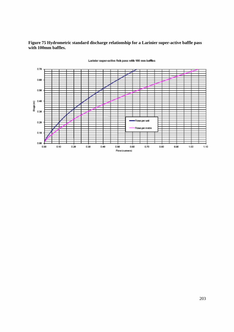
203
Figure 75 Hydrometric standard discharge relationship for a Larinier super-active baffle pass
with 100mm baffles.

204
Table 8 Numerical values for hydrometric standard discharge relationship for a Larinier super-
active baffle pass with 100mm baffles
205
Improvements at existing structures
Salmonids & Coarse fish
Clearly, it may be possible to apply a retro-fit solution that uses the ISO Standard outlined above to
modify an existing structure to become a compound gauging and fish pass facility. On the other hand,
other improvements to passage at existing gauging stations may well be possible utilising some of the
methods described in more detail in earlier sections. In the first instancea comparison of existing
conditions against the those outlined in the gauging & fish pass guidelines above may identify
features that can be readily modified to improve the situation e.g. reduction of afflux across the
structure, or improvement to approach conditions.
In some instances a fish pass solution such as a Larinier might be located in a by-pass channel with a
conventional gauging weir such as a Crump Weir located immediately upstream of it to gauge flow
accurately. The gauge weir would need a small afflux across it that meets the agreed guidelines. The
conditions required for a flow gauging adaptation at the head of a Larinier pass are described in
Chapters 4.6 of Flow measurement structure design to aid fish migration without compromising flow
data accuracy, Science Report SC020053/SR2, Environment Agency, January 2005.
The retro-fitting of a conventional fish pass solution other than those specifically included in the ISO
Standard is possible, including retro-fitting to non-standard gauges. In such cases the pass channel
would have to be fitted with an additional suitable flow gauge such as ultrasonic time of flight or
Doppler technology.
A relatively simple improvement may be the reduction of afflux, effectively the head difference
between crest of the gauge weir and tail-water level, by the provision of notched pre-barrages (notch
with streaming flow or adherent nappe as per examples in pool passes). This may be particularly
attractive where approach conditions are not less than acceptable at the moment sine it would help
address that issue as well as make passage over the structure easier, and where only one or two pre-
barrages have to be used. It would be helpful if the most downstream pre-barrage as a free gap rather
than a notch. The disadvantage of reducing afflux is that this will compromise i.e. reduce the range of
flows over which the station remains in the modular range. However, this may not be critical where
the station is a low flow device.
Although not yet accepted for widespread use a technique for Crump type weirs is a modification of
the Low Cost Baffle solution (LCB - see Easements section). This is currently the subject of ongoing
field-based R&D, but early indications suggest good potential –see LCB section. The LCB system has
to be compromised from its idealised form by placing the nearest baffles to the weir crest further
down the weir slope, such that the coefficient of discharge of the Crump weir is not altered by more
than 1%. The methodology for deciding where the most upstream baffle may be placed is described in
Chapter 5 of White, Bowker & McGahey, 2005, Flow measurement structure design to aid fish
migration without compromising flow data accuracy, Science Report SC020053/SR2, 2005.
Another baffle solution, the Hurn baffle solution, has been used for Flat V Weirs in a small number of
locations. This has been described in the Baffles section, page 131. The solution has not proved to be
effective for coarse fish species that appear to be disorientated by the turbulence and cannot find a
passage route. However, they are considered to help passage of salmonids. The same methodology for
locating the most upstream baffle would apply as described above for the LCB solution on Crump
Weir.

206
Eels
Eels are a particular challenge because, especially in their early most migratory phases as elver &
small eel, they are very poor swimmers. Eels require separate fish pass facilities from salmonids &
coarse fish. Various of the techniques briefly outlined in the earlier eel pass section might be used at
gauging stations, however in practice these are currently limited to the non-invasive techniques that
do not impair gauging station accuracy. Guidelines have been agreed between Fisheries &
Hydrometry and put in place as policy in November 2009. Non-invasive solutions for eel/elver
passage at gauging stations may be used as follows:
Definition of non-invasive: An eel pass that is located above and beyond the area bounded by the
wing walls of a gauging structure.
These may be installed subject to agreement between local fisheries and hydrometry teams
Provided that the design of non-invasive eel passes meets the following general principles then it is
expected that they will be an acceptable solution for use at gauging sites. In some cases invasive eel
passes may be acceptable at gauging stations, but the general presumption is they will not. The
following guidance should permit the identification of sites where the provision of eel passes is more
immediately possible e.g. these will usually be pipe or channel “up and over” type passes with elver-
friendly substrate and a pumped flow.
General Principles
1. Both entrance and exit need to be sited in a manner that is acceptable for eel passage1 while
not compromising the performance of the gauging structure2. The lower entrance to the pass
should be placed downstream of the end of the gauging weir wing wall. For hydrometric
reasons, the eel pass should be fed by water pumped from downstream of the structure
wherever possible.
2. The pump should abstract no more than 0.5 litres of flow / second3. This assumes that at least
half of the 0.5 litre per second is discharged back downstream. Less than half to be discharged
upstream of the structure.
3. Such passes can only be installed where minimum dry weather flow of the watercourse
exceeds 25 litres/ second.
4. The siting of the pass entrance and exit should be near the margins of the stream and not mid
– channel.
5. At a site where a high flow rating exists for the channel outside of the wing walls, the
hydrometry team will need to consider the impact of the eel pass on that high flow rating.
6. Agreement will need to be achieved between local fisheries and hydrometry and telemetry
teams on the design of the eel pass.
7. The hydrometry team can object to the installation of an eel pass if it considers it has
justifiable reasons. Adjudication of disputes will be resolved by the Regional Hydrometry and
Telemetry Client Panel.
Notes:
1 Near the toe of the obstruction
2 Avoids snagging debris or interfering with flow lines
3 Experience has shown that if correctly sited eels will find a very small attraction flow. The nominated flow is
sufficient for a bristle pass 200 mm wide that will allow thousands of eels to pass per night. The pump only

207
needs to be operating from dusk till dawn. Key months for use of pass: April-September with some Regional
variation.
The full temporary guidelines document can be found in the Appendix XVI.
It is expected that guidelines for a specific ‘invasive’ type of eel pass will shortly be agreed, and this
is the subject of ongoing R&D to confirm acceptance and agree detailed specific structural and
operational guidelines. This comprises a tall, narrow vertical structure with horizontal bristle media at
one or both banks of a gauging station. It may be suitable for many gauge structures but particularly
broad-crested and Crump Weirs for example. It is not especially suitable for some structures, such as
Flat V weirs.
Lampreys
Like eels, lampreys (sea & river lamprey) are not particularly good swimmers and require specific
arrangements to enhance passage. Given their unique ability to use their sucker mouthparts to
augment locomotory capability, a simple means of enhancing passage without interfering with
gauging accuracy is to provide a continuous stainless steel plate, say 0.3 – 0.5m wide up one or both
sides of the weir from the weir base on the downstream side to the river bed on the upstream side. The
crest should not form a sharp edge that might cause the lamprey to lose the vacuum created with the
villi in their sucking mouthparts.
Brook lampreys are a special case being very small (<15cms). It is quite possible that passage
solutions provided for eel & elver may be used by brook lamprey as well.

208
FISH PASSAGE AT WATER CONTROL STRUCTURES &
NAVIGATION LOCKS
Sluices and radial gates
Conventional water control structures are rarely designed with fish passage in mind. However, when
new structures are being installed or perhaps replacements during maintenance it is possible for them
to be constructed sympathetically. Modifications that can help improve the chances of fish passage are
discussed below.
It should never be forgotten that changes in the operating regime or defined protocol(s) for control
structures at existing sites might be used to bring about substantial improvements in fish passage.. By
moving the areas where the majority of the flow is discharged, or by creating different velocities and
flow patterns, the behaviour of the fish can be influenced and they may be dissuaded from entering
some areas while being guided or attracted to others. Careful observation of, or an understanding of,
fish behaviour in relation to the hydrodynamics at a site may facilitate the use of tactics that can
improve the effectiveness and efficiency of passage, for example to attract fish to an area where fish
can pass such as the location of a fishway.
Undershot Sluices
Undershot sluices control discharge by restricting the flow to a limited area under the gate. The mean
water velocity through the gate is related to the head difference across it and is the same as for head
differences in pool and traverse type fishways. The velocity is approximately equal to (2gh)0.5
for a
free flowing gate, while the discharge is roughly equal to velocity multiplied by the open area of the
gate. While these are only approximations because they ignore coefficients of discharge and
contraction, approach velocities, and also roughness, they are good enough for fishery purposes.
In the right circumstances undershot sluices can pass fish. As with orifices in pool passes, the open
aperture of the gate must be a minimum size of 0.3m x 0.3m, and the velocity through it should not
exceed 3ms-1
for migratory salmonids. A velocity of 3.0ms-1
would be generated by a head difference
of about 0.45m if the gate is free flowing. If the sluice opening is well submerged i.e. drowned, then a
head difference of 1m results in a velocity of about 2.7m-1
(see Appendix XI, Examples 9 & 10).
To improve the likelihood of achieving passable conditions it is better to regulate flow at such
structures by using multiple small gates that can be well open, as opposed to small numbers of very
large ones (see Figure 76 & Figure 77. Wide gates open by a small amount have attractive high
velocity jets that are impassable, and distract fish from finding more beneficial routes.
Ideally the sluice should discharge in to a stilling basin designed to bring the formation of the
hydraulic jump close to the structure, and to dissipate energy and the water velocity rapidly.
Extending the sill in to the basin and avoiding the use of base blocks is also an advantage. These
principles are demonstrated in Figure 78 & Figure 79.

209
Figure 76 Undershot sluices with flow regulated by multiple gates, permitting low discharges to
be achieved while providing suitable conditions for fish passage (After Beach, 1984)
Figure 77 A single large undershot gate controlling flow (often automated).A low discharge
results in an impassable high velocity jet (After Beach, 1984)

210
Figure 78 This form of undershot sluice is very unsuitable. The base block enables a water jet to
form, while the flat base allows the high velocity to persist over a considerable distance (After
Beach, 1984)
Figure 79 Fish passage at this form of undershot sluice is much easier. The lack of obstruction
below the sluice gate and graded approach to the stilling basin allow rapid attenuation of water
velocity (After Beach, 1984)

211
Overshot Sluices
Overshot sluices (Figure 80 & Figure 81) can permit fish passage provided that most of the conditions
required for pool type passes are mimicked. The head difference across the gate should not exceed
0.45m for migratory salmonids, less for other species. Velocities are calculated in the same way as for
undershot sluices or pool passes. The gate should have a rounded profile to ensure an adherent nappe,
and the pool below should be sufficiently deep - at least twice the head difference. Like the undershot
sluice it is preferable to have a stilling basin, and to regulate flow with a number of smaller sluices
that allow the appropriate conditions to be maintained at one or more of them.
The disadvantage of overshot sluices when compared to undershot is that the overshot sluice will
generally have the additional hazard for the fish of a solid spindle in the passageway. However, it is
possible to avoid this by having sluices with side-actuating spindles

212
Figure 80 Overspill sluice with sharp edge and shallow water over concrete apron; this
produces difficult approach conditions for fish because of insufficient downstream water depth
(After Beach, 1984)
Figure 81 Overspill sluice with curved edge and stilling basin; this produces sufficient water
depth for an easy approach and a smooth crest flow (After Beach, 1984)

213
Radial gates
Radial gates are only likely to be passable when they are drowned out during high river discharge
events. In normal circumstances there is a high velocity under partly open gates, with extreme
reverse-rolling turbulence that makes them unapproachable.
Navigation Locks
Navigation locks, by definition, are not intended for passing fish and are not usually located in a
position that would make them attractive to fish. Despite this the emptying phase of lockage can
attract fish in to the lock chamber. As a result fish can be accidentally, or even deliberately lifted
upstream (Klinge, 1994; Moser et al, 2000). Locks would not be considered as the principle means of
moving fish upstream, but nevertheless may be exploited to considerable advantage to augment more
conventional arrangements.
There are numerous examples from around the world of locks being used to enhance fish passage. In
the USA sites where locks are used include Bonneville Dam on the Columbia River, USA (Monan et
al 1970), Chittenden Locks on the Lake Washington Ship Canal, Seattle, USA (P. Gough, pers
comm), and the Cape Fear River (Moser et al, 2000.) All feature locks used with some success in this
way. Sites are also known in France (Jolimaitre,1992; Zylberblat & Mainali, 1996), Switzerland
(Kreitmann, 1925), and the USSR (Kipper & Mileiko, 1962). In the UK the technique has been used
with some success, although not as a regular operation, at the navigation lock at the River Tees
Barrage (R. Jenkins, pers comm). Early observations also suggest that fish might use navigation locks
associated with the Cardiff Bay Barrage on the River Taff (P. Gough, pers comm). Thus, while by no
means a primary means of providing fish passage it has been proved to be a useful ancillary one at
some locations.
There are a number of changes to the operational protocol for navigation locks that can be used to
increase their ability to act as a fish passage device. For example, in the USA passage of American
shad through locks on the Cape Fear River (Moser et al, 2000) was greatly enhanced by:
Operating the lock as a fish pass (i.e. a specifically designed protocol) during
appropriate periods
Increasing attraction flows from the lock entrance
Conducting as many lockages as possible in a day
Adjusting the position of the lock gates and local flow patterns to attract and retain
fish better.

214
At the Chittendon Locks ( Lake Washington Ship Canal, Seattle), the large lock is regularly left in a
part open position (with a gap of perhaps 0.5m), creating a through-flow that successfully promotes
the migration of sockeye salmon (P. Gough, pers comm).
On the Cape Fear River (Moser et al, 2000) the locks were originally operated over one cycle per day
during the shad migration period. Fish were attracted in to the lock over a 24hr period by opening the
sluices on the upstream gates, while leaving the downstream gates open. At the end of the 24hr period
the downstream gates were shut and the lock filled. Once full the upstream gates were opened, and at
the same time the sluices on the downstream gates were opened in order to create a flow that
encouraged the shad to leave the lock. Modifications to this protocol included increasing lockages to
three times per day, shutting one of the downstream gates to help prevent fish leaving the lock, and
opening the sluices that directed flow down the lock wall where the downstream gate was open. These
adjustments were carefully made after observation of the behaviour of the shad in the lock.
A typical operating protocol might be:
Lock empty, crack top gate sluices, run flow through cracked lock gates (if the design will
stand this) or else say one gate open (increases attraction, re-directs fish back up the lock
rather than swimming back out) developing a small head drop (attraction velocity) and
streaming flow entrance.
Run for a period of time to attract fish in
Close downstream gates and fill lock
Open upstream gates, and crack downstream gate sluices to generate a current that encourages
fish to leave the lock
This protocol is precisely similar to the operation of a Borland Lift.

215
FISH PASS EVALUATION AND MAINTENANCE
The need for monitoring the performance of a fish pass
The approval of fish passes is dealt with under section 11 of the Salmon and Freshwater Fisheries Act
1975. This can be a two-stage process; the first being to submit detailed proposals and obtain
Provisional Approval, the second stage being to submit details on how the fish pass is performing in
order to obtain Final Approval. There is thus may be a requirement to monitor the performance of a
fish pass.
When considering an application for Provisional Approval, the Environment Agency expects
information to be supplied not only on the design and operation of the fish pass, but also on how it is
intended to assess the performance of the pass. The aim of this section and Appendix XIV is to outline
how such data might be obtained.
Introduction
The performance of a fish pass will vary with the type of pass, species and specific site conditions
(Katapodis, 1992). There is a considerable amount of information both published and unpublished
which indicates that fish passes can be effective in that they are known to pass fish (Beach, 1984;
Clay, 1995; Katapodis, 1992). Similarly there is considerable evidence that fish passes have been
constructed which have proved to be ineffective in passing their target species; mainly as a result of
poor/unsuitable design.
While there is a considerable literature on the effectiveness of fish passes, there is not a great deal of
information on fish pass efficiency. This is largely because of the considerable resource requirement
required to complete such studies. Table 9 summarises the estimates of efficiency for some fish passes
for salmon.

216
Table 9 Efficiency of various fish passes for salmon
Type of Pass Location ( river ) Efficiency Reference
Denil Blackweir (Taff) 25 - 39% Gough (pers.comm)
Denil Pau River 34% Chanseau & Larinier
(1999)
Submerged Orifice Pitlochry (Tummel) 45.5%
86 - 100%
Webb (1990)
Gowans et al.(1996)
Various (31 sites) Pau River 35 – 100% Chanseau, Croze &
Larinier (1999)
Borland Fish Lift Kilmorack (Beauly) 40% Smith et al.(1996)
Various(6 sites) River Conon 63 - 100% Gowans et al (2001)
Various (21 sites) River Thames 65 – 100% Clifton-Dey (pers.
comm.)
The three-year study carried out on the Pau River tracked 114 salmon, and looked at thirty-one sites
equipped with fishways varying from natural by-pass channels, to technical constructions. Overall
efficiencies of passage varied from 35.3% to 100%. Those sites with 100% efficiency were
characteristically those that caused delays to passage of no more than two weeks, while those with
efficiencies less than 100% were characterised by significant numbers of fish being delayed for
periods longer than this. Those fishways that were efficient were also those that cause the least delay,
and there was an inverse relationship between the two factors.
The Pau River tracking study also demonstrates clearly that when considering the efficiency of a pass
it is not simply the proportion of fish approaching the obstruction that subsequently get past that has
to be considered, but also the time that it takes. This becomes a particularly important consideration
when the fish absolutely must pass in order to achieve their objective, foe example when all the
spawning grounds for migratory salmonids lie upstream of the obstruction. In France, a fish pass for
migratory salmonids would generally be expected to achieve an efficiency of >80% and to delay fish
for less than two weeks to be regarded as acceptable.
The study on the River Thames took place over several years (1995 - 2004 ) and reflects passage past
the weir with fish pass as opposed to the fish pass alone. This is because these low weirs, generally
1.5 - 2m high, are not wholly impassable and some fish can pass either over the weirs or else through
flow and head regulation structres at elevated river discharge. However, they mostly remain
impassable and often for long periods without the passes.
Some estimates of efficiency exist for other species, including shad and grayling. For shad on the
River Garonne, the percentage passing through the Golfech lift and the pass at Bazacle (pool pass
with vertical slots) ranged from 17 - 32% (Larinier & Travade,1992) and at Ramier the fish pass was
estimated to be >70% efficient (Dartiguelongue, 1990 in Larinier & Travade,1992). On the Dordogne
at Mauzac the efficiency of the pool pass, for shad, ranged from 0.5 - 30% (Larinier & Travade,

217
1992). For grayling, Linlokken (1993) estimated the efficiency of pool and weir and a Denil fish
passes to be <2%. No estimates of fish pass efficiency are known for cyprinids and eels.
For species not indigenous to Europe, estimates of efficiency have been reported for Micropterus
dolomieui and Catostomus commersoni using a Denil fish pass, of 50% and 33% respectively (Bunt et
al, 1999).
Some reasons for undertaking evaluation
The scope of any monitoring programme will depend on the nature of the fish pass and its potential
impact on the fish stocks. The reasons for an evaluation programme fall into three main categories as
follows; to improve operational efficiency of the fish pass, to assess the level of any mitigation that
might be required for a poorly performing pass, and to to improve future designs.
To appraise operation
To confirm the functioning of the pass for the target fish species over the range of
environmental conditions in which migration occurs. For example, the upstream
migration of salmonids can occur throughout the year and it is important that a fish
pass is able to facilitate their passage at all times, without undue delay.
To confirm the functioning of the pass for each component of the fish stock. For
example, it is important that the ability of the pass to assist passage of each age class
or length class of the target fish species is confirmed and that the pass is not size
selective.
To provide information to enable improvements to be made to the operation of the
fish pass if required.
To collect information and data (qualitative and/or quantitative) to support a future
application for Final Approval under the SAFFA, 1975 (as amended by the
Environment Act, 1995).
To determine the proportion of the target migrating stock which succeeds in
ascending the pass (or descending a downstream pass).
To assess mitigation
To provide data for the assessment of any mitigation required. For example, a
Fisheries Compensation Scheme associated with a major new obstruction to
migration may require information on the efficiency of the fish pass in order to
quantify the required level of mitigation.

218
To improve future designs
To enhance the overall sum of knowledge on the functioning and performance of fish
passes in order to promote future improvements in design and construction.
The requirements for monitoring
Types of assessment
In principle there are two ways of monitoring and judging the performance of a fishway.
Detecting changes in the upstream population
The detection of change in the upstream population indicates whether or not the pass is effective i.e. is
it "capable of passing fish in the desired direction". It may be either a quantitative or quailitative
assessment of the performance of the fish pass.
Assessing the efficiency of the pass
The proportion of available fish using the pass is the efficiency of a fish pass and is a quantitative
measure of its performance. In its simplest form Efficiency (E) is that proportion (n) of the available
stock of fish (N) which succeed in ascending/descending a fish pass.
E = n/N .............................................................................................. (1)
Where it is obligatory that all fish must pass, such as a migratory salmonid population arriving at a
barrier downstream of any potential spawning habitat, then this is a simple scenario. Where not all
fish arriving at or near an obstruction need to pass, the efficiency might better be assessed relative to
the numbers of fish that approach the barrier or pass that intend to move upstream.
Further complexity is added when considering the element of delay. An efficient fish pass is not
necessarily one that simply passes a high proportion of the fish. It is one that passes a high proportion
of the fish without undue delay. How important the latter is depends on the context. A single
obstruction near the lower end of a long river catchment, or a number of obstructions on even a short
river catchment, clearly mean that the element of delay becomes an important issue.
Factors affecting the required precision
The potential magnitude of the impact of any development on the fish population is an important
consideration. Two primary situations can be recognised. The situation where a new obstruction is
being created that imposes a new constraint on the fish population, and the situation where the
existing effects of an obstruction are being mitigated by the installation of a fishway.

219
Existing structures
On an existing structure, the criteria to be fulfilled are lower than for new structures, as any
improvement in potential access to the river upstream is desirable. As long as fish are witnessed to
pass over or through the structure then it is evident that the fish pass has made a difference. However,
it is important when applying for final approval that some assessment of the effectiveness of the pass
is presented. In these cases the quality of the data required to assess effectiveness does not usually
need to be as robust as when a pass on a new structure is being considered.
New structures
For a fish pass on a new structure the actual efficiency of the pass must usually be determined. In
circumstances where there is a significant risk that the new structure will have a detrimental effect on
the migratory salmonid population, a quantitative monitoring programme capable of determining
passage efficiency will be required.
In this case the context of delay will be much more likely to be an important issue. There is evidence
that fish delayed for more than one to two weeks from entering a river may disappear never to return
(Solomon et al, 1999). The work on the Pau River (Chanseau & Larinier, 1999) showed that highly
efficient passes in terms of both proportion of fish passing and short delay were associated with delay
periods of less than two weeks.
The intensity of the required monitoring programme will depend on the risk that a structure poses to
the population. An intensive monitoring programme is likely to be required for a development in the
estuary or lower reaches of a major migratory salmonid river where risk to the population is high. On
the other hand the programme can be less intensive for a new development on a tributary in the upper
reaches of a river where the perceived risks are low.
Cumulative effect of a number of structures
The importance of monitoring is particularly apparent in the case of rivers where multiple
obstructions to migration exist. If each of a series of ten fish passes on a river operated at an
efficiency of 50%, then the migrating stock of fish ascending the whole series would be reduced to
only 0.1% of its initial number. An alternative way of looking at this from the point of view of a
fishery manager is to imagine that a spawning escapement of 100 fish is required to reach the
uppermost stretch of the river. Even with the greater fish pass efficiency of 80%, a stock of 1000 fish
would need to arrive at the first obstruction to achieve the target escapement above the top one.
Clearly, on watercourses with diadromous fish populations and multiple obstructions it is essential for
fish passage facilities to be highly efficient, near 100%.
The rapid decline in the number and proportion of fish reaching the spawning area as the number of
obstructions increases, and the efficiency of passes declines is demonstrated in Figure 82. The initial
number of migrating fish is assumed to be one thousand, and the lines represent different mean
efficiencies between 100% and 50%.

220
Figure 82 Effects of fish passage efficiency in river systems where a series of passes are
constructed along the migratory route for salmonids (After Gowans, 1998)
0
100
200
300
400
500
600
700
800
900
1000
0 5 10 15 20 25 30 35 40 45 50
Number of fish passes in series
Estim
ate
d n
um
ber
of
successfu
l m
igra
nts
100%
99%
95%
90%
80%70%
60%
50%
0
100
200
300
400
500
600
700
800
900
1000
0 1 2 3 4 5 6 7 8 9 10
Number of fish passes in series
Estim
ate
d n
um
ber
of
successfu
l m
igra
nts
100%
99%
95%
90%
80%70%60%50%

221
Relative position and importance of the obstruction within the catchment
The monitoring associated with a pass on an existing structure in a tributary which improves the
potential for migration will not require as robust a programme as a pass within a major new
obstruction in the lower reaches of a river. The former may require simple operational or observation
data only (eg. redd counts, lack of accumulation of potential migrants downstream), whilst the latter
may require a major monitoring programme requiring pre and post-construction monitoring
programmes involving the collection of quantitative data, and the accurate assessment of pass
operating efficiency.
Criteria for evaluation
Fish pass performance is likely to vary between fish species and also according to the size and
condition of the fish. It is also likely to be affected by flow, and the relationship between pass
performance and flow may mean that it varies both throughout the run of fish (e.g. different for spring
and summer components of the stock), and from year to year. As an example, Larinier & Travade
(1992) reported that river flows often had a marked effect on fish pass efficiency for Alosa spp, with
low flows being optimal for shad to use the fish passes. In these cases the relative attraction flow from
the passes was higher at times of low river discharge.
It is essential that the estimation of performance of a pass should take account of the variability in
environmental conditions, but particularly flow, as well as the timing of the fish migration and other
factors. For this reason it is important, when dealing with species such as salmon or eel that have
relatively large windows of migration, to stratify the sampling programme. In practice this will
usually mean that monitoring needs to extend not only throughout a season, but also usually over
more than one season. This is to ensure that actual variation in the conditions a species might be
expected to experience as well as their physiological state (i.e. how close the fish is to spawning) are
taken into account.
Different species and life stages
The criteria for monitoring may be different for different species, and even life stages of the same
species. For example, for those species which have a relatively short migration period (eg. Alosa
spp.), or a late running population of salmon say, it is imperative that any delay to their migration be
kept to a minimum. In the case of migratory salmonids it is frequently the case that the whole of the
spawning population is obliged to cross an obstruction in order to reach the spawning grounds that are
located upstream. However, in the case of cyprinids, where the main biological objective is to avoid
the population becoming isolated, it is not necessary to ensure that the whole population migrate pass
the obstruction, as long as a reasonable proportion of the population can do so (Porcher & Travade,
1992).

222
Hydraulic factors and flow
Monitoring should also include measurement of the hydraulic conditions in the pass under a variety of
flows. This is to ensure that the pass meets the original design criteria, and thus its suitability for the
particular target species. Also to ensure and confirm that the facility operates effectively across the
expected range of river discharge and levels.
Methods for determining the effectiveness of fish passes
The effectiveness of a pass is a qualitative description of the performance of a pass. It simply
demonstrates that some fish are able to use the pass and, even though numbers of fish recorded using
the facility may be very high, it cannot necessarily be taken as an indication of good performance of
the fishway. The effectiveness of a pass can be determined either directly or indirectly (see below).
The relative merits of the main methods (both direct and indirect) that can be used to monitor the
effectiveness of a fish pass are shown in Table 10.
Table 10 The relative merits of the main methods that can be used to monitor the effectiveness
of a fish pass
Method of Assessement
Effectiveness
Visual Inspections
+
Rod Catches
++
Redd Counts
++
Fishery Surveys
+++
Telemetric Surveys
PIT tag,Radio tag etc
++++
Fish Counter - in pass
Resistivity, Video, Infra-red
++++
Fish Counter - in pass with
information on population d/s
++++
Counter + Photo/Video
++++
Trapping and tagging
++++

223
Direct assessment of effectiveness
Confirmation that fish are using a fish pass can be accomplished through direct means including
visual inspection, photography, trapping in the fish pass, or from recordings on a fish counter (see
Fewings 1994 for various types). Design criteria for resistivity counters can be found in Nicholson et
al. (1995), and for automatic video recording systems in Travade & Larinier (1992b). One of the
limitations of using methods such as fish counters is that they need a power supply. In those instances
where no power source is available other methods of assessing effectiveness will be required, and
these include indirect methods.
Indirect assessment: Detecting changes in the upstream population
These methods involve the assessment of the status of juvenile and/or adult stocks pre and post-
construction of the fish pass. If data on the juvenile and/or adult population are to be used to assess
the effectiveness of the pass then the study must be based on a statistically robust experimental design
(see Wyatt & Lacey, 1994). Some worked examples of assessing effectiveness are given in Appendix
XIV.
Methods for determining the efficiency of a fish pass
The efficiency of a pass is a quantitative measure of its performance. It is the proportion of the fish
that approach the facility that successfully pass. It is a sound indicator of performance, although then
effects of delay may also need to be taken in to account in some instances.
The relative merits of the main methods that can be used to monitor the efficiency of a fish pass are
shown in Table 11.
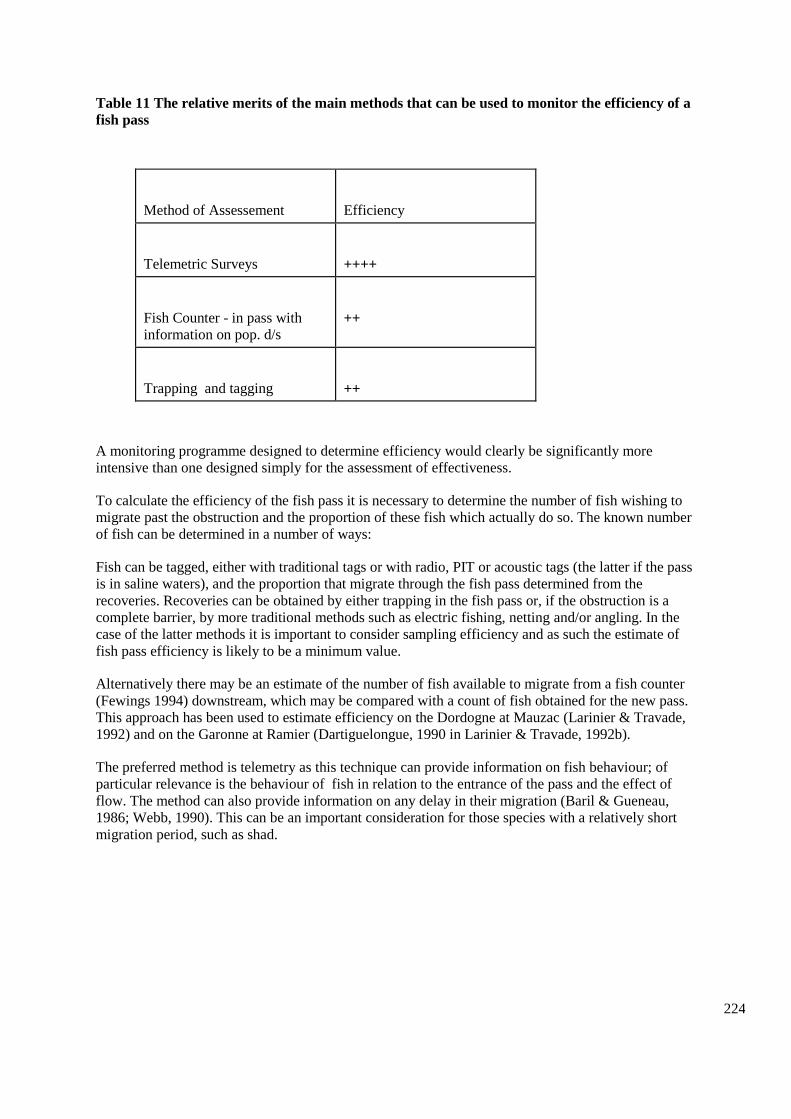
224
Table 11 The relative merits of the main methods that can be used to monitor the efficiency of a
fish pass
Method of Assessement
Efficiency
Telemetric Surveys
++++
Fish Counter - in pass with
information on pop. d/s
++
Trapping and tagging
++
A monitoring programme designed to determine efficiency would clearly be significantly more
intensive than one designed simply for the assessment of effectiveness.
To calculate the efficiency of the fish pass it is necessary to determine the number of fish wishing to
migrate past the obstruction and the proportion of these fish which actually do so. The known number
of fish can be determined in a number of ways:
Fish can be tagged, either with traditional tags or with radio, PIT or acoustic tags (the latter if the pass
is in saline waters), and the proportion that migrate through the fish pass determined from the
recoveries. Recoveries can be obtained by either trapping in the fish pass or, if the obstruction is a
complete barrier, by more traditional methods such as electric fishing, netting and/or angling. In the
case of the latter methods it is important to consider sampling efficiency and as such the estimate of
fish pass efficiency is likely to be a minimum value.
Alternatively there may be an estimate of the number of fish available to migrate from a fish counter
(Fewings 1994) downstream, which may be compared with a count of fish obtained for the new pass.
This approach has been used to estimate efficiency on the Dordogne at Mauzac (Larinier & Travade,
1992) and on the Garonne at Ramier (Dartiguelongue, 1990 in Larinier & Travade, 1992b).
The preferred method is telemetry as this technique can provide information on fish behaviour; of
particular relevance is the behaviour of fish in relation to the entrance of the pass and the effect of
flow. The method can also provide information on any delay in their migration (Baril & Gueneau,
1986; Webb, 1990). This can be an important consideration for those species with a relatively short
migration period, such as shad.

225
From tagging studies efficiency can be estimated as follows (Travade & Larinier, 1992b):
E = np/ANm ................................................................................................... (2)
where:
E = efficiency as a proportion
np = number of marked fish that migrate through the fish pass
Nm = number of marked fish
A = proportion of fish which die as a result of tagging and handling.
The level of precision and confidence that can be attached to measures of efficiency of fish passes by
using different sample sizes of fish is addressed in APPENDIX XIV Monitoring Programme
Examples.
Conclusion
Though the methods are well understood on how to assess the effectiveness and determine the
efficiency of a fish pass, there are still important questions to be answered. Namely what level of
efficiency should a fish pass achieve and should this affect whether a fish pass receives Final
Approval? For example, if a fish pass does not achieve a pre-determined level of efficiency should
mitigation be requested, or should modifications to the structure, or the operating regime be
compulsory? Obviously some of this will depend on the nature of the problem and whether the pass is
placed on a new or existing structure, as discussed in section 6.3.2. Consideration should also be
given to the level of precision and confidence that the study aims to achieve, as these have a
significant impact on the resource requirement. It is also important that the monitoring programme is
commensurate with the benefits that the installation of the pass aims to achieve. To enable
comparison between the costs of monitoring and the benefits of constructing a fish pass the benefits
need to be determined in monetary terms (see Milner & Power, 1996, Appendix VIII).
When assessing effectiveness using population change there will be usually little pre construction data
on the particular river which can be used to design the sampling programme. Therefore it will be
necessary to use data, ideally from similar river systems in order to help determine the number of sites
and the duration of the study. At present there is a paucity of such data, and it would be useful to
construct a database relating the various components of variance to river type and species. This
database could then be used to assist with the development of a monitoring programme.
When determining the effectiveness and efficiency of a particular type of fish pass it is important to
record all the relevant conditions. These include the local hydrological conditions, the hydraulic
conditions within the pass, the target species and size of fish, and the location of the pass (particularly
the entrance in relation to the obstruction and the flow).
Consideration should also be given to the measurement of the delay to migration, which in certain
instances can be considerable (Baril & Gueneau, 1986; Webb, 1990, Chanseau & Larinier, 1999). The

226
effect of delaying fish on their spawning migration could result in fish spawning on or in sub-optimal
habitat, which may lead in turn to a decline in recruitment. Therefore it is important to ensure that
delay is minimal.
Fish Pass Maintenance
Legal Position
There is a legal duty under Section 9(1) of SAFFA, 1975, for fish passes for migratory salmonids to
be maintained in an efficient state, and it is an offence under the Act not to do so. Responsibility rests
with the legal owner or occupier of the structure or land on which the fish pass is constructed. Where
passes are constructed by the Agency, responsibility for maintenance of the pass would normally be
transferred to the Agency by a legal agreement. Where any person fails in this duty, the Agency may
carry out any necessary works to ensure compliance and recover the costs of the works in summary
manner.
To ensure that this aspect of fish passage has been considered, the Agency Fish Pass Approval
Process requires the owner of the fish pass, and the site where it is constructed if different, to be
identified. It also requires confirmation of whom will be responsible for carrying out the maintenance,
when and how. These details should be submitted with the application for Provisional Approval.
Generally we should be aiming to ensure that the pass achieves at least 90% availability during the
required period of operation. The required operating period should be clearly defined.
Inspection
Clearly there is no point in investing in a fish pass structure to improve fish passage if it is not
checked to ensure that the pass has not been rendered ineffective through temporary blockages from
trash or bed load movement, or by damage to the structure itself. This is potentially an onerous task
that can consume considerable resources. Careful selection of the type of fish pass itself, anticipation
of the needs for maintenance, and the incorporation in to the design of structures such as penstocks
and trash screens can minimise the risk of obstructions to migration occurring and facilitate ease of
maintenance.
Where the pass has no moving parts it is recommended that structural maintenance, ensuring that the
fabric of the structure is in good repair, should be carried out not less than every 3-5 years. Checks
should be made to ensure that the pass still mets its specification, for example, in the case of Plane
Baffle Denils the baffles themselves should be replaced when they become <8mm thick.
Operational maintenance, that is ensuring that its function is not impaired, should be carried out on an
`as needs` basis. The plan for operational maintenance thus needs to be subject to some form of risk
analysis as the pass is commissioned, but in time will reflect experience at the specific site. Both
structural and operational maintenance will clearly be much more onerous in terms of required
frequency where the fishway has moving parts.

227
It should not be forgotten that an important aspect of maintenance is to ensure that the pass is, and
continues to, operate in the way that it was intended. The fact that the pass has been constructed
correctly according to the design specifications should be checked before the pass is commissioned. It
is also very useful to install water level gauge-boards, bearing the design operating ranges of the pass,
both upstream and downstream of the structure. This will help ensure that the pass is operating within
the expected limits of river discharge and water levels.
Where attraction to the pass relies to some extent on the operating procedures for other nearby
structures, then the operating practices for those structures should be reviewed from time to time to
ensure that they are:
operating as expected, and
do indeed maximise attraction to the pass.
The programme of maintenance and inspection is left to local management to determine, but should
comprise a schedule of frequency of visits that should be tailored to the period when the pass needs to
operate. A number of factors will influence the decision about frequency of maintenance visits. These
will include, for example: whether the obstruction is total or partial, type of pass, relative location in
the catchment, hydrographic regime in the river, geology of the catchment in respect of sediments,
and type of plant growth in the river and on the banks. Take for example a fish pass high up in a
catchment, it may need to be checked weekly during the spawning season but only quarterly at other
times of the year. On the other hand, a pass low down a catchment with plenty of woody debris may
need to be checked weekly or more frequently throughout the period when fish are running.
In the case of migratory salmonids, wild brown trout, and shad populations a simple initial risk
assessment might take the following form. The two main risk factors are the position in the catchment
(P) and vulnerability to blockage (B).
Then creating a table to take the combination of the two factors in to account gives:
Table 12 Risk assessment for maintenance requirement of a fish pass
PB Pb
pB pb
PB = Low down catchment, High risk of blockage = weekly inspection
Pb = Low down catchment, Low risk of blockage = fortnightly inspection
pB = High up catchment, High risk of blockage = fortnightly inspection
pb = High up catchment, Low risk of blockage = monthly inspection

228
The frequency of inspection and operational maintenance would follow the guideline during the
relevant period of migration, with the latter needing to be carefully defined. After a suitable period
during which experience is gained it should be possible to adjust the programme of visits to suit the
individual site.
In the case of fish passes for coarse fish it is suggested that monthly inspection and maintenance
during the spawning season, i.e. March to June inclusive, is good enough for most species, most of the
time.
Outside of the relevant migration period(s) it is clearly unnecessary to visit the site. However, a first
visit should be made a suitable period before the anticipated start of migration to ensure that there is
sufficient time to rectify any problems. Should a pass be conjunctively used for canoe passage or
other public amenity purposes, or if any Public Safety Control Measures PSCMs) are an issue, then
this may affect the frequency of inspection required.
Remote Surveillance
An alternative that may be worth considering is the installation of remote video surveillance. If the
site is not very remote from human development then power and data communications may be
available. Modern ADSL lines are commonly available within 4 km of a communications substation
and many providers can assess the availability from the postcode of the nearest dwelling. With at least
an ADSL line and AC power remote monitoring by network video camera is possible. This technique
allows any personal computer with an ADSL connection and a web-browser or proprietary software
to view the video output of the site camera(s) on the computer from any remote location. Additional
features allow the camera to be controlled remotely for actions such as zoom, pan, tilt and focus. For
suitable sites, a routine visual inspection for debris blockage could be carried out in a few minutes as
often as required.
For sites where power and cable communications are not available it is possible to employ the mobile
phone short message service features to relay detected blockages at remote sites. This does of course
depend on mobile phone network coverage, but where suitable coverage is available this system is
able to run the communications and water level sensors for extended periods of time. The blockages
can be detected by a number of means, but perhaps the simplest is the detection of a large increase in
the difference in water level between that of the water upstream of the fishway, and that in the pass
near the discharge point.
For very remote locations it is possible to employ similar means to the water level difference/mobile
phone scheme described above, but using the alternative of satellite based mobile phone networks.
Unfortunately they are not only more expensive and bulkier but also generally have larger power
consumption. As a result power from solar and or wind generators may be required.
In summary, there are many ways in which fish pass sites may be routinely checked for blockages and
other problems without the need for a site visit. As technology improves and becomes cheaper, while
labour costs escalate, this is increasingly attractive option.
229
Inspection Records
A basic form is included in Appendix XII Maintenance inspections for fish passes constructed by
external developers should also be made available to the Agency as and when local management
requires. Where appropriate, inspection will need to include monitoring of PSCMs and Safety
systems.
Remedial Action
Where a blockage is identified we should aim for it to be removed within three working days during
the defined period when the fish pass should be in operation, subject to a safe system of work being
feasible. This standard of service can be relaxed outside the defined period, to a time-scale considered
reasonable by local management.
It is recommended that, in the case of an external developer a written requirement for remedial works
to be undertaken should be faxed to them, identifying the legal requirement and a reasonable time-
scale for completion of works. Failure to comply should result in formal action, the severity of which
should clearly take into account any extenuating circumstances.
Where the fish pass has suffered structural damage repair is very unlikely to be feasible within the 3
day standard. Therefore repairs should be completed as soon as practically possible, always bearing in
mind that we should aim for an overall standard of 90% availability during the defined operating
period.

230
REFERENCES
Key References
Anon. (2000). River Crossings and Migratory Fish: Design Guidance. A consultation document
produced by the Scottish Executive. Also available on the internet at http://www.scotland.gov.uk
Beach, M. H. (1984). Fish pass design - criteria for the design and approval of fish passes and other
structures to facilitate the passage of migratory fish in rivers. Fish. Res. Tech. Rep., MAFF Direct.
Fish. Res., Lowestoft (78), pp. 46.
Clay, C. H. (1995). Design of fishways and other fish facilities Second edition. London: Lewis
Publishers. pp. 248.
Clough, S.C., & Turnpenny, A.W.H. (2001). Swimming Speeds in Fish: Phase 1. R&D Technical
Report W2-026/TR1. Environment Agency.
Fish Passes - Design, Dimensions and monitoring. 2002. Published by FAO/DVWK (Food and
Agriculture Organisation of the United Nations and Deutscher Verband fur Wasserwirtschaft und
Kulturbau e.V). Rome. ISBN 92-5-104894-0. Available from Publishing Management Service,
Information Division, FAO, Viale delle Terme di Caracalla, 00100 Rome, Italy.
Jungwirth, M., Schmutz,S., & Weiss,S. (Eds).(1998). Fish Migration and Fish Bypasses. Oxford:
Fishing News Books. pp. 438.
Carling, P.A., and Dobson, J.H., (1992). Fish pass design and evaluation. National Rivers Authority
R&D Note 110.
Environment Act, 1995. HMSO Publications.
Larinier, M., Travade, F., Porcher., 2002: Fishways: biological basis, design criteria and monitoring. Bull.
Fr. Peche Piscic., 364 suppl., 208p. ISBN 92-5-104665-4. Copies can be purchased from Conseil
Superieur da la Peche, Centre du Paraclet, B.P. n 5, 80440 BOVES, France. Cost 32 Euros. E-mail:
Salmon and Freshwater Fisheries Act, 1975. HMSO Publications.
Solomon D.J., & Beach M.H., 2004: Manual for provision of upstream migration facilities for Eel &
Elver. Science Report SC020075/SR2. Environment Agency.
The Eels (England and Wales) Regulations 2009. HMSO Publications.

231
Specific References
Adams, R.D., & Reinhardt, U.G. (2008). Effects of texture on surface attachment of spawning-run sea
lampreys (Petromyzon marinus): a quantitative analysis. J.Fish.Biol, 73, 1464-1472.
Aitken, P.L. Dickerson, L.H., & Menzies ,W. J. M. (1966). Fish passes and screens at water-power
works. Proc. Inst. Civil Engineer, 35, 29-57.
Andrew, F.J. (1990). The use of vertical-slot fishways in British Columbia, Canada. In: Proc. Int.
Symp. on fishways, Gifu, Japan, pp 267-274.
Anon. (1942). Report of the Committee on Fish Passes. Instn. Civ. Engrs., London, pp.59.
Anon. (1993). Design Manual for Roads and Bridges. Department of Transport/Scottish Office
Industry Department/Welsh Office/Department of the Environment for Northern Ireland. London,
HMSO.
Anon. (1995). Re-appraisal of options to facilitate the upstream migration of Dace. Internal NRA
Report.
Anon. (1995). Notes for Guidance on the Provision of fish passes and screens for the safe passage of
salmon. The Scottish Office Agriculture & Fisheries Department. HMSO Scotland. ISBN 0 7480
3105 Y.
Anon. (1997). Project Management in the Agency. Vol 014. Version 2. 04/97. Environment Agency.
Anon. (1997). EA Training manual on screening intakes and outfalls.
Anon. (1999). Environment Agency Policy Regarding Culverts, Policy Statement, Explanation of
Policy & Technical Guidance on Culverting Proposals.
Anon, (2000). River Crossings and Migratory Fish: Design Guidance. A consultation document
produced by the Scottish Executive. Also available on the internet at http://www.scotland.gov.uk.
Anon. (2002). Scoping Guidance on the Environmental Impact Assessment (EIA) of Projects. Also
available on the intranet at: http://intranet2.ea.gov/Organisation/National/NCRAOA/EIA/contents.htm
Bates. K. (1990). Recent experience in cost efficient fish passage in Washington State. In: Proc.Int.
Symp. on fishways. Gifu, Japan. pp335-342.
Bates, K. (1997). Fish passage at road culverts. In: Fishway design guidelines for Pacific salmon.
Working paper 1.6,1/97. Washington Department of Fish & Wildlife. pp11-13 to 11-21.
Baril, D. & Gueneau, P. (1986). Radio-pistage de saumons adultes (Salmo salar) en Loire. (Radio-
tracking of adult salmon in the river Loire). Bull. Fr. Pêche Piscic. 302: 86-105.
Beach, M. H. (1984). Fish pass design - criteria for the design and approval of fish passes and other
structures to facilitate the passage of migratory fish in rivers. Fish. Res. Tech. Rep., MAFF Direct.
Fish. Res., Lowestoft (78), pp. 46.

232
Beamish, F.W.H. (1978). Swimming capacity. In: Fish physiology. Hoar, W.S. London, Academic
Press: 101-187.
Belford, D.A. & Gould, W.R. (1989). An evaluation of trout passage through six highway culverts in
Montana. North American Journal of Fisheries Management 9, 437-455.
Bell, M. C. (1986). Fisheries Handbook of Engineering Requirements and Biological Criteria. U.S.
Army Corps of Engineers, North Pac. Div., Portland, Oregon, USA. pp 290.
Boiten, W. (1990). Hydraulic design of the pool-type fishway with V-shaped overfalls. In: Proc.Int.
Symp. on fishways. Gifu, Japan. pp483-490.
Boiten, W., & Dommerholt, A. (2005).Standard design of the Dutch pool and orifice fish pass. J.
River. Basin. Management 4(3), 219-227.
Bunt, C., Katapodis, C. & McKinley, R. S. (1999). Attraction and passage efficiency of white sucker
(Catostomus commersoni) and smallmouth bass (Micropterus dolomieui) by two Denil fishways.
North American Journal of Fisheries Management 19, 793-803.
Bussell, R.B. (1978). Fish counting stations – notes for guidance in their design and use. London;
Dept of the Environment. pp70.
Butterworth, A.J. (1993) The use of hydroacoustics for fish stock assessment in freshwater. Paper
presented at Hydroacoustics workshop Royal Holloway College, Egham, Surrey, April 1993.
Carling, P.A. & Dobson, J.H. (1992). Fish pass design and evaluation. National Rivers Authority
R&D Note 110. pp161.
Castros-Santos, T. (2005). Optimal swim speeds for traversing velocity barriers: analysis of volitional
high-speed swimming behaviour of migratory fishes. J. Exp. Biol 208, 421-432.
Chanseau, M., Croze, O., & Larinier, M. (1999). Impact des amenagements sur la migration anadrome
du saumon atlantique (Salmo salar L.) sur le gave de Pau (France) (The impact of obstacles on the Pau
River (France) on the upstream migration of returning adult Atlantic salmon (Salmo salar L.). Bull.
Fr. Pêche Piscic, 353-354, 211 - 238.
Chanseau, M., & Larinier, M. (1999). Etude du comportment du saumon atlantique (Salmo salar L.)
au niveau de l’ amenagement hydroelectrique de Baights (gave de Pau) lors de sa migration anadrome
(The behaviour of returning adult Atlantic salmon (Salmo salar L.) in the vicinity of Baights
hydroelectric power plant on the Pau River as determined by radiotelemetry). Bull. Fr. Pêche Piscic,
353-354, 239 - 262.
Clay, C. H. (1995). Design of fishways and other fish facilities Second edition. pp 248. London:
Lewis.
Clough, S., and Ladle, M. (1997). Diel migration and site fidelity in a stream-dwelling cyprinid,
Leuciscus leuciscus (L.). J. Fish. Biol, 50, 1117-1119.
Clough, S. C. & Turnpenny, A. W. H. (2001). Swimming speeds of freshwater fish. Phase 1. R&D
Technical Report No. W2-026/TR1 & 2. Bristol: Environment Agency.
Clough, S C, Lee-Elliott, I E, Turnpenny, A W H, Holden, S D J and Hinks, C (2004) Swimming
speeds in fish: Phase II. R&D Technical Report W2-049/TR1. Bristol: Environment Agency.

233
Clough, S C, Lee-Elliott, I E, Turnpenny, A W H, Holden, S D J and Hinks, C (2004) The
swimming speeds of twaite shad (Alosa fallax). R&D Technical Report W2-049/TR3. Bristol:
Environment Agency
Clough, S C and Turnpenny, A W H (2004) Swimming speeds in fish: Phase II literature review.
R&D Technical Report W2-049/TR2. Bristol: Environment Agency
Clyde, M. (1996). A cost benefit analysis of fish pass construction on the Garth Dulas, a tributary of
the River Irfon. Internal Technical Memo. SE/EAU/96/11.
Crump, E.S. (1952). A new method of gauging stream flow with little afflux by means of a submerged
weir of triangular profile. Proc. Instn. Civ. Engnrs, 1, 223-242.
Dahl, J. (1991) Eel passes in Denmark, why and how. EIFAC Working Party on Eels, Dublin, May
1991.
Dartiguelongue, J. (1990). Monitoring the downstream and upstream migration at the Ramier fish
passage facility in spring 1990. Rep. EDF-CSP. pp 41.
Denil, G. (1909). Les echelles a poissons et leur application aux barrages de Meuse et d`Ourthe (Fish
ladders and their use at the Meuse and Ourthe dams). Bull. Acad. Sci. Belg, pp1221-1224.
Fewings, G. A. (1994). Automatic salmon counting technologies - a contemporary review. Atlantic
Salmon Trust, Pitlochry, Perthshire, Scotland. ISBN 1 870875 22 2.
Fewings, G. A. (1998). Fish counters – The procs. of a seminar in Perth, Scotland April 1997. Atlantic
Salmon Trust, Pitlochry, Perthshire, Scotland. ISBN 1 870875 57 5.
Forbes, H. E., Smith, G. W., Johnstone, A. D. F., & Stephen, A. B. (2002). Testing the effectiveness
of changes to the operation of a Borland lift fish pass. Fisheries Research Services Report No 05/02.
Scotland.
Fort, R.S. & Brayshaw, J.D (1961). Fishery Management. London, Faber & Faber. pp398.
Gebler, R-J. (1998). Examples of Near-natural Fish Passes in Germany: Drop Structure Conversions,
Fish Ramps and Bypass Channels. In Fish Migration and Fish Bypasses (Jungwirth, M., Schmutz, S.
&, Weiss, S. ed), pp434. Oxford:Fishing News Books.
Gowans, A. R. D., Armstrong, J. D. & Priede, I. G. (1996). Ascent of adult salmon through a pool and
orifice fish ladder in Scotland. In Fish Migration and Fish Bypasses (Jungwirth, M., Schmutz, S. &,
Weiss, S. ed), pp434. Oxford:Fishing News Books.
Gowans, A.R.D. (1999). Movements of adult Atlantic salmon (Salmo salar L.) in relation to
hydroelectric schemes in Scotland. University of Aberdeen: PhD Thesis. pp145 + figures.
Gowans, A.R.D, Armstrong, J.D., Priede, I.G., & McKelvey, S. (2003). Movements of Atlantic
salmon through a fish-pass complex in Scotland. Ecol. FW. Fish, 12, 177-189.
Haro, A., Castros-Santos, T., & Norieka,J. (2004). Evaluation of passage performance of a deepened
(Model A40) Alaska Steepass fishway for American shad (Alosa sapidissima) and White Sucker
(Catostomus commersoni). Report for CAFRC – S.O. Conte Anadromous Fish Research Center.
15pp.
234
Harris, J. H., Thorncraft, G. &, Wem, P. (1998). Evaluation of Rock-Ramp Fishways in Australia. In
Fish Migration and Fish Bypasses (Jungwirth, M., Schmutz, S. &, Weiss, S. ed), pp434.
Oxford:Fishing News Books.
Hassinger, R. & Kraetz,D. (2006). The canoe-fishway – a combination of fish migration facility and
canoe passage in the same channel. EIFAC, 24th EIFAC Symposium on Hydropower, Flood Control
and Water Abstractions; Implications for Fish and Fisheries, Mondsee, 2006.
Herschy, R.W, White, W.R, & Whitehead, E,. `The Design of Crump Weirs`, Technical
Memorandum No 8, February 1977, Department of the Environment, Water Data Unit Report, ISBN
0 904871 08 8. pp73.
Hyldegaard, P., and Peterson, S. (1999). Alternative fish passages - sweeps and bypasses. In
Proceedings of the First Nordic Conference on Fish Passage. Oslo, Sept 1998.
Huet, (1949). Apercu des relations entre la pente et les populations piscicoles des eaux courantes.
(Observations on the relationships between the slope and the fish populations in flowing waters).
Schweitzer Zeitschrift fur Hydrologie,11, 322-51 (in french).
Ing, R. and Gebler, J., (2007) Rock Ramps and nature –like-bypass channels, Design criteria and
experiences, EIFAC Working Party Fish Passage best practisis, Salzburg, October 8-10, 2007
Jolimaitre, J.F. (1992). Franchissement pour l’alose feinte de l’ amenagement de la chute de
Vallabregues: etude du franchissement de l’ecluse de navigation. Avante projet de passes a poisson
sur le seuil de Beaucaire. CSP. pp42.
Katapodis, C.P. (1992). Introduction to fishway design. Working document. Freshwater Institute,
Dept. of Fisheries & Oceans, Canada.
Kipper, Z.M., & Mileiko, I.V. (1962). Fish passes in the Soviet Union. Rybn. Khoz, pp73, (In
Russian).
Klinge, M. (1994). Fish migration via the shipping lock at the Hagestein Barrage: results of an
indicative study. Wat. Sci. Tech, 29(3), 357-361.
Knights, B. & White, E.M. (1998). Enhancing immigration and recruitment of eels: the use of passes
and associated trapping systems. Fisheries Management and Ecology 5, 459-471.
Kreitmann, L. (1925). Passes a poisson et lacs de barrage en Suisse. Compte rendu de mission
piscicole. Ministere de l’Agriculture, Direction Generale des Eaux et Forets. pp 43.
Laine, A., Kamula, R., & Hooli, J. (1998). Fish and lamprey passage in a combined Denil and
Vertical Slot fishway. Fisheries Management & Ecology, 5, 31-44.
Larinier, M. (1984). Dispostif mixte passe a poissons-glissiere a canoe-kayak (Dual purpose passage
facility for fish and canoes). Preliminary unpublished report, pp19.
Larinier, M. (1990). Experience in fish passage in France: fish pass design criteria and downstream
migration problems. In Proceedings of the International Symposium on Fishways, 1990, Gifu, Japan.
Larinier, M. (2002a). Pool fishways, pre-barrages and natural bypass channels, pp 54-82). In Larinier,
M., Travade, F., Porcher., 2002: Fishways: biological basis, design criteria and monitoring. Bull. Fr.
Peche Piscic., 364 suppl., 208p. ISBN 92-5-104665-4.

235
Larinier, M. (2002b). Biological factors to be taken into account in the design of fish passage
facilities, the concept of obstructions to upstream migration, pp28-38. In Larinier, M., Travade, F.,
Porcher., 2002: Fishways: biological basis, design criteria and monitoring. Bull. Fr. Peche Piscic., 364
suppl., 208p. ISBN 92-5-104665-4.
Larinier, M. (2002c). Location of fishways. In Larinier, M., Travade, F., Porcher., 2002: Fishways:
biological basis, design criteria and monitoring. Bull. Fr. Peche Piscic., 364 suppl., 208p. ISBN 92-5-
104665-4.
Larinier, M. (2002d) Baffle fishways, pp83-101. In Larinier, M., Travade, F., Porcher., 2002: Fishways:
biological basis, design criteria and monitoring. Bull. Fr. Peche Piscic., 364 suppl., 208p. ISBN 92-5-
104665-4.
Larinier, M. (2002e) Fish passage through culverts, rock weirs and estuarine obstructions, pp119-134.
In Larinier, M., Travade, F., Porcher., 2002: Fishways: biological basis, design criteria and monitoring.
Bull. Fr. Peche Piscic., 364 suppl., 208p. ISBN 92-5-104665-4.
Larinier, M. (1996). Fishpass design criteria and selection. In: Mann, R.H.K & Aprahamian, M.W.
(eds). (1996). Fish Pass Technology Training Course, Inst FW Ecol, Dorset.
Larinier, M., & Chorda, J. (1995) Prise en compte de la migration du poisson lors de la conception des
ouvrages de rétablissement des écoulements naturels dans les aménagements routiers ou autoroutiers
(Fish passage design at road and motorway crossings). GHAAPPE Rep. 95.01, 11p
Lariner, M., & Miralles, A. (1981). Etude hydraulique des passes a ralentisseurs (Hydraulic study of
Denil fishways). Unpublished report, CEMAGREF. pp53.
Larinier, M., and Travade, F. (2002). The design of fishays for shad, pp135-146. In Larinier, M.,
Travade, F., Porcher., 2002: Fishways: biological basis, design criteria and monitoring. Bull. Fr. Peche
Piscic., 364 suppl., 208p. ISBN 92-5-104665-4.
Linlokken, A. (1993). Efficiency of fishways and impact of dams on the migration of grayling and
brown trout in the Glomma river system, South-eastern Norway. Regulated Rivers Research &
Management 8, 145-153.
Litaudon, A. (1985). Observations preliminaires sur le franchissement du seuil de Saint-Laurent-des-
Eaux (Loire) par l’alose (Alosa alosa). Rapp. EDF HE/31/85-37. Pp63.
Lucas, M.C., Thom, T.J., Duncan, A. & Slavik, O. (1998). Coarse fish migration: occurrence, causes
and implications. Environment Agency R&D Technical Report W152.
Lucas, M.C., Percival, F.M., & Bubb, H. (2006). Review of factors affecting the passage of sea
lamprey at obstructions – insights from European and North American knowledge. Report of a
collaborative project with the Environment Agency. Durham University.
Mallen-Cooper,M., & Stuart,I.G. (2007). Optimising Denil fishways for passage of small fish and
large fishes. Fisheries Mnanagement & Ecology, 14: 61 -71.
Mallen-Cooper, M., Zampatti.,B., Stuart,I., & Baumgartner,L (2008). Innovative Fishways –
Manipulating Turbulence in the Vertical Slot Design to Improve Performance and Reduce Cost.
Fishway Consulting Services Report for Murray-Darling Commission, Pp19.
236
Mann, R.H.K & Aprahamian, M.W. (eds). (1996). Fish Pass Technology Training Course, Inst FW
Ecol, Dorset.
McKinley, W.R., & Webb, R.C. (1956). A proposed correction of migratory fish problems at box
culverts. Washington Department of Fisheries, DC, Research Papers, 1(4).
Milner, N. & Power, E. (1996). Selection of fish pass options. In Fish Pass Technology Training
Course, Inst FW Ecol, Dorset, pp 127-142.
Mitchell, C.P. (1995). Fish passage problems in New Zealand. In: Proceedings of the International
Symposium on Fishways, 1995, Gifu, Japan. pp33-41.
Monan, G., Smith, J., Liscom, K., & Johnson, J. (1970). Evaluation of upstream passage of adult
salmonids through the navigation lock at Bonneville dam during the summer of 1969. Fourth Progress
Rep. on Fish. Eng. Res. Prog. 1966-1972. U.S. Army Corps of Eng, North Pacific Div, 104-113.
Moser, M.L., Darazsdi, A.M. & Hall, J.R. (2000). Improving passage efficiency of adult American
Shad at low-elevation dams with navigation locks. N. Am. J. Fish. Man, 20, 376-385.
Moser, M.L., Ocker, P.A., Stuehrenberg, L.C., & Bjornn, T.C. (2002). Passage efficiency of adult
Pacific lampreys at hydropower dams on the lower Columbia River, USA. Trans. Am. Fish. Soc, 131,
956-965.
NMFS (National Marine Fisheries Service). 2008. Anadromous Salmonid Fish Passage Facility
Design. NMFS, Northwest Region, Portland, Oregon.
Nakamura, S. (1995). Recent habitat restoration and fish passage efforts in Japanese streams. Seminar
at Freshwater Institute, Central & Arctic Region, Fisheries and Oceans, 501 University Crescent,
Winnipeg, Canada.
Nicholson, S.A., Aprahamian, M.W., Best, P.M., Shaw, R.A., & Kaar, E.T. (1995). Design and use of
fish counters. National Rivers Authority, R&D Note 382. pp203.
Northcote, T.G. (1984). Mechanisms of fish migrations in rivers. In: Mechanisms of Migration in
Fishes (eds McCleave, J.D., Arnold, G.P., Dodson, J.J., & Neill,W.H.), pp317-355. Plenum Press,
New York and London.
O’Connor, L., Pratt, T.C., Hallett, A.G., & Katopodis, C. (2004). Sea lampreys (Petromyzon marinus)
in the laurentian Great Lakes: Mitigating low-head barriers impacts using a modified vertical slot
fishway. In Aquatic Habitats: Analysis and Restoration, Fifth International Symposium on
Ecohydraulics. (Lastr, D.G. & Matinez, P.V. eds), pp p73 -978. Madrid: International Association of
Hydraulic Engineering and Research and Universidad Politecnica de Madrid.
O’Connor, L., Pratt, T., Hallett, A., Katopodis,C., Bergstadt, R., Hayes, D., and McLaughlin, R.
(2003). Performance evaluation of fishways at sea lamprey barriers and controlled modifications to
improve fishways performance. Report to Great Lakes Fishery Commission (see
http://www.glfc.org/research/scr.php).
O’Keefe, N., & Turnpenny, A.W.H. (2005). Screening for Intakes and Outfalls: a best practice guide.
Science Report SC030231. Environment agency. 153pp.

237
Parasiewicz, P., Eberstaller, J., Weiss, S., & Schmutz, S. (1998). Conceptual guidelines for nature-like
by-pass channels. In Fish Migration and Fish Bypasses (Jungwirth, M., Schmutz, S. &, Weiss, S. ed),
pp348-362. Oxford:Fishing News Books.
Paeke, S.J., & McKinley, R.S. (1998). A re-evaluation of swimming performance in juvenile
salmonids relative to downstream migration. Can. J. Fish. Aqua. Sci, 55, 682-687.
Peake, S.J., & Farrell, A.P. (2004). Locomotry behaviour and post-exercise physiology in relation to
swimming speed gait transition and metabolism in free-swimming small mouth bass (Micropteris
dolomieu). J. Exp. Biol 207, 1563-1575.
Porcher, J.P. (2002). Fishways for eels, pp147-155. In Larinier, M., Travade, F., Porcher., 2002:
Fishways: biological basis, design criteria and monitoring. Bull. Fr. Peche Piscic., 364 suppl., 208p.
ISBN 92-5-104665-4.
Porcher, J. P. & Travade, F. (2002). Fishways: biological basis, limits and legal considerations, pp 9-
20. In Larinier, M., Travade, F., Porcher., 2002: Fishways: biological basis, design criteria and
monitoring. Bull. Fr. Peche Piscic., 364 suppl., 208p. ISBN 92-5-104665-4.
Pryce-Tannatt, T.E. (1938). Fish passes in connection with obstructions in salmon rivers. Buckland
lectures for 1937. pp108. London: Edward Arnold & Co.
Rajaratnam, N., Van der Vinne, G., & Katopodis, C. (1986). Hydraulics of vertical slot fishways. J.
Hydr. Eng, 112 (10), 909-927.
Rajaratnam, N., Katopodis, C., & Lodewyk, S. (1988). Hydraulics of offset baffle culvert fishways.
Can. J. Civil. Eng, 15 (6), 1043-1051.
Rajaratnam, N., Katopodis, C., & Mainali. A. (1989). Pool and pool-orifice-weir fishways. Can.J.
Civil. Eng, 16 (5), 774-777.
Rajaratnam, N., Katopodis, C., & McQuitty, N (1989). Hydraulics of culvert fishways II: slotted-weir
culvert fishways. Can. J. Civil. Eng, 16 (6), 375-383.
Rajaratnam, N., & Katopodis, C. (1990a). Hydraulics of culvert fishways III: weir baffle culvert
fishways. Can. J. Civil. Eng, 17 (4), 558-568.
Rajaratnam, N., & Katopodis, C. (1990b). Hydraulics of culvert fishways V: Alberta fish weirs and
baffles Can. J. Civil. Eng, 17 (6), 1015-1021.
Rajaratnam, N., Katopodis, C., & Lodewyk, S. (1991). Hydraulics of culvert fishways IV: spoiler
baffle culvert fishways. Can. J. Civil. Eng, 18 (1), 76-82.
Rajaratnam, N., Katopodis, C., & Solanki, S. (1992). New designs for vertical slot fishways. Can. J.
Civil Eng, 19 (3), pp 402-414.
Rhodes, D. G., & Servais, S.A. ((2008). Low-cost modifications of the Crump weir to improve fish
passage. Science Report SC010027. Environment Agency. 76pp.
Rideout, S., Thorpe, L., & Cameron, L. (1985). Passage of American shad in an Ice Harbor style fish
ladder after flow modifications. Symp on small hydropower and fisheries, Aurora, Colarado, pp 251-
256.

238
Rizzo, B. (1969). Fish passage facilities design parameters for Connecticut River dams. Turners Falls
dam. Bureau of Sport Fisheries and Wildlife, Boston, Massachusetts, pp 32.
Rizzo, B. (1986). Fish passage design information. Fish passageways and diversion facilities course,
Merrimack, New hampshire, pp26.
Servais, S. A. (2006). Physical modelling of low-cost modifications to the Crump weir in order to
improve fish passage: development of favourable swimming conditions and investigation of the
hydrometric effect. PhD Thesis, Cranfield University. Engineering Systems Department, Shrivenham,
Swindon, UK.
Slatick, E,. & Basham, L.R. (1985). The effect of Denil fishway length on passage of some
nonsalmonid fishes. Marine Fisheries Review, 47(1),pp83-85.
Smith, G. W., Johnstone, A. D., & F. Shearer, W. M. (1996). The behaviour of returning adult
Atlantic salmon (Salmo salar L.) at a Borland lift fish pass as determined by radio telemetry. SOAFD
Fisheries Research Services Report No. 7/96.
Solomon, D.J. (1992). Diversion and entrapment of fish at water intakes and outfalls. NRA R&D
Rep.1, 51pp.
Solomon, D. J. & Beach, M.H. (2004). Fish pass design for eel and elver (Anguilla anguilla). R&D
Technical Report W2-070/TRI. Environment Agency. 92pp.
Solomon, D.J. & Beach, M.H. (2004). Manual for provision of upstream migration facilities for Eel
and Elver. Science Report SC020075/SR2. Environment Agency. 63pp.
Solomon, D.J., Sambrook, H.T., & Broad, K.J. (1999) Salmon migration and river flow: results of
tracking radio tagged salmon in six rivers in South West England. Environment Agency R&D
publication 4. ISBN 1 873160 88 7. pp110.
Sprengel, G. & Luchtenberg, H. (1991). Infection by endoparasites reduces maximum swimming
speed of European smelt Osmerus eperlanus and the European eel Anguilla anguilla., Dis. Aquat.
Org., 11, 31-35.
Stuart, I.G., & Mallen-Cooper, M. (1999). An assessment of the effectiveness of a vertical-slot
fishway for non-salmonid fish at a tidal barrier on a large tropical/subtropical river. Regulated Rivers:
Research & Management, 15, pp 575-590.
Tarrade,L., Texier,A., David,L., & Larinier,M. (2008). Topologies and measurements of turbulent
flow in vertical slot fishways. Hydrobiologia, 609:177-188.
Travade, F. & Larinier, M. (2002a). Fish locks and fish lifts, ppp102-118. In Larinier, M., Travade,
F., Porcher., 2002: Fishways: biological basis, design criteria and monitoring. Bull. Fr. Peche Piscic., 364
suppl., 208p. ISBN 92-5-104665-4.
Travade, F. & Larinier, M. (2002b). Monitoring techniques for fishways, pp 166-180. In Larinier, M.,
Travade, F., Porcher., 2002: Fishways: biological basis, design criteria and monitoring. Bull. Fr. Peche
Piscic., 364 suppl., 208p. ISBN 92-5-104665-4.
Travade, F., Larinier, M., Trivellato, D., & Dartiguelongue. (1992). Conception d'un ascenseur a
poissons adapte a l'alose (Alosa alosa) sur un grand cours d'eau : l'ascenseur de Golfech sur la

239
Garonne. (Design of a fish pass for shad (Alosa alosa) on a large watercourse: fish pass at Golfech on
the river Garonne). Hydroecol. Appl. Tome 4 (1), 91-119.
Turnpenny, A.W.H. (1989). Impoundment and abstraction – exclusion of fish from intakes. In: Procs.
Of a workshop on the safeguarding of fisheries, Univ. Lancaster, April 1988. (Ed Gregory, J).
Pitlochry, Atlantic Salmon Trust. 87-114.
Turnpenny, A W H, Blay, S R, Carron, J J and Clough, S C (2001) Literature review of swimming
speeds of freshwater fish. R&D Technical Report W2-026/TR2. Bristol: Environment Agency.
Walters, G. A. (1996a). Hydraulic Model Tests on the Proposed Fish Pass Structure for Hurn
Gauging Weir, Dorset; Exeter Enterprises, April 1966.
Walters,G. A. (1996b). Hydraulic Model Tests on the Proposed Fish Pass Structure for Hurn Gauging
Weir, Dorset; Exeter Enterprises, July 1966. Supplementary Report.
Wardle, C. S. (1975). Limit of fish swimming speed. Nature, Lond., 255; 725-727.
Washburn, E., Gregory, J., & Clabburn, P. (2008). Using video images for fisheries monitoring: A
manual for using underwater cameras, lighting and image analysis. Science Report SC050022/SR2.
Environment Agency. 66pp.
Webb, J. (1990). The behaviour of adult Atlantic salmon ascending the Rivers Tay and Tummel to
Pitlochry dam. Scottish Fisheries Research Report No. 48.
White, R., Bowker, P., & McGahey, C. (2005). Flow measurement structure design to aid fish
migration without compromising flow data accuracy. Science Report SC020053/SR2. Environment
Agency. 175pp.
Wyatt, R. J. & Lacey, R. F. (1994). Guidance notes on the design and analysis of river fishery
surveys. R&D Note 292, National Rivers Authority, Bristol.
Zaidman, M.D., Lamb, R., Mawdsley, J., Lawless, M.R., Archer, D.R., & Melching, C.S. (2005).
Non-invasive techniques for river flow measurement. Science Report SC030230/SR. Environment
Agency. 188pp.
Zhou, Y., (1982). The swimming behaviour of fish in towed gears; a re-examination of the principles.
Scott. Fish. Work. Pap., Dept. Agric. Fish. Scotl.,m 94), 1-55.
Zylberberblat, M., & Mainali, J. Y., (1996). Upstream passage of migratory fish through navigation
locks. Ecohydraulics, June 1996, Quebec. B829-B841.

240
Acknowledgements
We are extremely grateful to all our colleagues and to the publishers who have given help or
permissions for the reproduction of illustrative material included in this manual:-
Ken Bates for his advice concerning Flap Gates & kind permission to reproduce Figure 16, Figure 59
& Figure 60
Mike Beach & CEFAS, Lowestoft for kind permission to reproduce British Crown Copyright (1984)
material and many figures from Fisheries Research Technical Report No 78 (see full reference in
bibliography)
Mike Beach for reviewing the first manual, making correcting and editorial suggestions to improve
the accuracy and content of this next version.
DJ Gent for re-drawing figure Figure 49
Andy Gowans for kind permission to reproduce Figure 82
John Harris, Garry Thorncraft, Peter Wem & Blackwell Publishing for kind permission to reproduce
Figure 47 (see full reference in bibliography)
Peter Hyldegaard & Svend Petersen for kind permission to reproduce figure Figure 49 (see full
reference in bibliography)
HMSO for permission to reproduce extracts of the Salmon & Freshwater Fisheries Act, 1975 as
amended by the Environment Act, 1995
Rolg-Jurgen Gebler & Blackwell Publishing for kind permission to reproduce Figure 48 (see full
reference in bibliography)
Brian Knights, M. White & Blackwell Publishing for kind permission to reproduce Figure 62 (see full
reference in bibliography)
We are especially grateful to Michel Larinier, Jean Porcher, François Travade & the Conseil
Supérieur de la Pêche for kind permission to reproduce so many figures from their excellent
publication - Fishways: Biological basis, design criteria and monitoring (see full reference in
bibliography)
Michel Larinier, A.Miralles & CEMAGREF for kind permission to reproduce Figure 35 & Figure 36
from Caracteristiques hydrauliques des passes a ralentisseurs (monitoring (see full reference in
bibliography)
Piotr Parasiewicz, Juergen Eberstaller, Steven Weiss, Stefan Schmutz & Blackwell Publishing for
kind permission to reproduce Table 5
N. Rajaratnam, Chris Katopodis, S. Solanki & the Canadian Journal of Civil Engineering for kind
permission to reproduce Figure 12 (see full reference in bibliography)
Gordon Smith, A. Johnstone & W. Shearer for kind permission to quote material from their paper (see
full reference in bibliography)
Waterman Industries Inc for kind permission to reproduce Figure 61 from their sales literature

241
Dave Charlesworth for his experience and advice on the practicalities of fixing baffles to cuverts and
the like.
Reinhard Hassinger and Daniel Kraetz for kind permission to use material from their paper to 24th
EIFAC Symposium on Hydropower, Flood Control and Water Abstractions; Implications for Fish and
Fisheries, Mondsee, Austria, 2006.
Atkins plc. For kind permission to reproduce Figure 50
FishFlow innovations nl. For kind permission to reproduce Figure 40.

242
APPENDICES
APPENDIX I Manual Feedback Form
FISH PASS MANUAL FEEDBACK FORM
1. Document reference including version & publication date
2. Your name & title
3. Your position
4. EA Region & Area
5. Organisation (if not EA)
6. Date of comments
7. Full postal address
8. Telephone Number
9. Generic comments
10. Specific comments (please give specific section & page number)

243
APPENDIX II Legislation
The Salmon and Freshwater Fisheries Act 1975 as modified (bold text) by
the Environment Act 1995
Source Her Majesty’s Stationery Office (HMSO)
Fishing Mill Dams
Section 8.
(1) No unauthorised fishing mill dam shall be used for taking or facilitating the taking of
salmon or migratory trout.
(2) A fishing mill dam shall not be used for the purpose of taking salmon or migratory
trout unless it has attached to it a fish pass of such form and dimensions as may be
approved by the Agency and unless the fish pass is maintained in such a condition
and has constantly running through it such a flow of water as will enable salmon and
migratory trout to pass up and down the pass.
(3) If any person:-
(a) uses an unauthorised fishing mill dam as mentioned in subsection (1) above: or
(b) uses or attempts to use a dam in contravention of subsection (2) above,
he shall be guilty of an offence.
(4) If a fishing mill dam has not a fish pass attached to it as required by law, the right of
using the fishing mill dam for the purpose of taking fish shall be deemed to have
ceased and be for ever forfeited, and the water authority for the area may remove

244
from it any cage, crib, trap, box, cruive or other obstruction to the free passage of the
fish.
Part II
(5) In subsection (1) above "unauthorised fishing mill dam" means any fishing mill dam
which was not lawfully in use on 6th August 1861, by virtue of a grant or charter or
immemorial usage.
Duty To Make And Maintain Fish Passes
Section 9.
(1) Where in any waters frequented by salmon or migratory trout -
(a) a new dam is constructed or an existing dam is raised or otherwise altered so as to
create increased obstruction to the passage of salmon or migratory trout, or any
other obstruction to the passage of salmon or migratory trout is created, increased or
caused; or
(b) a dam which from any cause has been destroyed or taken down to the extent of one
half of its length is rebuilt or reinstated,
the owner or occupier for the time being of the dam or obstruction shall, if so required by
notice given by the Agency and within such reasonable time as may be specified in the notice,
make a fish pass for salmon or migratory trout of such form and dimensions as the Agency
may approve as part of the structure of, or in connection with, the dam or obstruction, and
shall thereafter maintain it in an efficient state.

245
(2) If any such owner or occupier fails to make such a fish pass, or to maintain such a
fish pass in an efficient state, he shall be guilty of an offence.
(3) The Agency may cause to be done any work required by this section to be done, and
for that purpose may enter on the dam or obstruction or any land adjoining it, and
may recover the expenses of doing the work in a summary manner from any person in
default.
(4) Nothing in this section -
(a) shall authorise the doing of anything that may injuriously affect any public
waterworks or navigable river, canal, or inland navigation, or any dock, the supply of
water to which is obtained from any navigable river, canal or inland navigation,
under any Act of Parliament; or
(b) shall prevent any person from removing a fish pass for the purpose of repairing or
altering a dam or other obstruction, provided that the fish pass is restored to its
former state of efficiency within a reasonable time; or
(c) shall apply to any alteration of a dam or other obstruction, unless -
(i) the alteration consists of a rebuilding or reinstatement of a dam or other obstruction
destroyed or taken down to the extent of one half of its length or
(ii) the dam or obstruction as altered causes more obstruction to the passage of salmon
or migratory trout than was caused by it as lawfully constructed or maintained at any
previous date.
Power Of The Agency To Construct And Alter Fish Passes
Section 10.

246
(1) The Agency may construct and maintain in any dam or in connection with any dam a
fish pass of such form and dimensions as it may determine, so long as no injury is
done by such a fish pass to the milling power, or to the supply of water of or to any
navigable river, canal or other inland navigation.
(2) The Agency may abolish or alter, or restore to its former state of efficiency, any
existing fish pass or free gap, or substitute another fish pass or free gap, provided
that no injury is done to the milling power, or to the supply of water of or to any
navigable river, canal or other inland navigation.
(3) If any person injures any such new or existing fish pass, he shall pay the expenses
incurred by the Agency in repairing the injury, and any such expenses may be
recovered by the Agency in a summary manner.
Approvals for fish passes
Section 11.
(1) Any approval given by the Agency to or in relation to a fish pass may, if in giving it
the Agency indicates that fact, be provisional until the Agency notifies the applicant
for approval that the pass is functioning to its satisfaction.
(1A) The applicant for any such approval -
(a) shall be liable to meet any costs incurred (whether by him or by the Agency or any
other person) for the purposes of, or otherwise in connection with, the performance
of the Agency's function of determining for the purposes of subsection (1) above
whether or not the fish pass in question is functioning to its satisfaction; and
(b) shall provide the Agency with such information or assistance as it may require for
the purpose of performing that function.
(2) While any such approval is provisional, the Agency may, after giving the applicant
not less than 90 days notice of its intention to do so, revoke the approval.

247
(3) Where the Agency revokes a provisional approval given to a fish pass forming part of
or in connection with a dam or other obstruction, it may extend the period within
which a fish pass is to be made as part of or in connection with the obstruction.
(4) The Agency may approve and certify any fish pass if it is of opinion that it is efficient
in all respects and for all purposes, whether it was constructed under this Act or not.
(5) Where a fish pass has received the approval of the Agency, and the approval has not
been revoked, it shall be deemed to be a fish pass in conformity with this Act,
notwithstanding that it was not constructed in the manner and by the person specified
in this Act.
Penalty for injuring or obstructing fish pass or free gap
Section 12.
(1) If any person
(a) wilfully alters or injures a fish pass; or
(b) does any act whereby salmon or trout are obstructed or liable to be obstructed in using a
fish pass or whereby a fish pass is rendered less efficient; or
(c) alters dam or the bed or banks of the river so as to render a fish pass less efficient; or
(d) uses any contrivance or does any act whereby salmon or trout are in any way liable to be
scared, hindered or prevented from passing through a fish pass,
he shall be guilty of an offence, and shall also in every case pay any expenses which maybe
incurred in restoring the fish pass to its former state of efficiency; and any such expenses may
be recovered in a summary manner.
(2) The owner or occupier of a dam shall be deemed to have altered it if it is damaged,
destroyed or allowed to fall into a state of disrepair, and if after notice is served on
him by the Agency he fails to repair or reconstruct it within a reasonable time so as
to render the fish pass as efficient as before the damage or destruction.

248
(3) If any person
(a) does any act for the purpose of preventing salmon or trout from passing through a fish
pass, or takes, or attempts to take, any salmon or trout in its passage through a fish pass;
or
(b) places any obstruction, uses any contrivance or does any act wherby salmon or trout may
be scared, deterred or in any wayprevented from freely entering and passing up and down
a free gapat all periods of the year,
he shall be guilty of an offence.
(4) This section shall not apply to a temporary bridge or board used for crossing a free gap,
and taken away immediately after the person using it has crossed.
Restrictions on taking salmon or trout above or below an obstruction or in mill races
Section 17.
(1) Any person who takes or kills, or attempts to take or kill, except with rod and line, or
scares or disturbs any salmon or trout -
a) at any place above or below any dam or any obstruction, whether artificial or
natural, which hinders or retards the passage of salmon or trout, being within 50
yards above or 100 yards below the dam or obstruction, or within such other distance
from the dam or obstruction as may be prescribed by byelaw; or
b) in any waters under or adjacent to any mill, or in the head race or tail race of any
mill, or in any waste race or pool communicating with a mill; or
c) in any artificial channel connected with any such dam or obstruction, shall be guilty
of an offence.

249
(2) Nothing in this section shall apply to any legal fishing mill dam not having a crib, box
or cruive, or to any fishing box, coop, apparatus, net or mode of fishing in connection
with and forming part of such a dam or obstruction for purposes of fishing.
(3) Where a fish pass:
(a) approved by the Agency, or
(b) constructed and maintained by the Agency in accordance with section 10(1) above.
is for the time being attached to a dam or obstruction, this section shall not be enforced in
respect of the dam or obstruction until compensation has been made by the Agency to the
persons entitled to fish in the waters for that right of fishery.
Provisions supplementary to Part II
Section 18.
1) If any person obstructs a person legally authorised whilst he is doing any act
authorised by section 9, 10 or 15 above, he shall be guilty of an offence.
2) The Agency shall not -
a) construct, abolish or alter any fish pass, or abolish or alter any free gap, in
pursuance of section 10 above, or
b) do any work under section 15 above,

250
unless reasonable notice of its intention to do so (specifying the section in question)
has been served on the owner and occupier of the dam, fish pass or free gap,
watercourse, mill race, cut, leat, conduit or other channel, with a plan and
specification of the proposed work; and the Agency shall take into consideration
any objections by the owner or occupier, before doing the proposed work.
3) If any injury is caused -
a) to any dam by reason of the construction, abolition or alteration of a fish pass or the
abolition or alteration of a free gap in pursuance of section 10 above; or
b) by anything done by the Agency under section 15 above,
any person sustaining any loss as a result may recover from the Agency compensation for the
injury sustained.
4) The amount of any compensation under section 10, 15 or 17 above shall be settled in
case of dispute by a single arbitrator appointed by the Minister.
5) In any case in which the Agency is liable to pay compensation under this Part of this
Act in respect of injury or damage caused by the making or maintaining of any work,
compensation shall not be recoverable unless proceedings for its recovery are
instituted within two years from the completion of the work.
Note: Section 15 concerns screening

251
Water Resources Act, 1991
Source Her Majesty’s Sationary Office (HMSO)
PART VIIII LAND AND WORKS POWERS
I POWERS OF THE AUTHORITY
Provisions in relation to land
154 Compulsory purchase etc
(1) The Authority may be authorised by either of the Ministers to purchase compulsorily any land anywhere in
England and Wales which is required by the Authority for the purposes of, or in connection with, the carrying out of
its functions.
(2) The power of each of the Ministers under subsection (1) above shall include power—
(a) to authorise the acquisition of interests in, and rights over, land by the creation of new interests and rights; and
(b) by authorising the acquisition by the Authority of any rights over land which is to be or has been acquired by the
Authority, to provide for the extinguishment of those rights.
(3) Without prejudice to the generality of subsection (1) above, the land which the Authority may be authorised under
that subsection to purchase compulsorily shall include land which is or will be required for the purpose of being given
in exchange for, or for any right over, any other land which for the purposes of the [1981 c. 67.] Acquisition of Land
Act 1981 is or forms part of a common, open space or a fuel or field garden allotment.
(4) Subject to section 182 below, the Acquisition of Land Act 1981 shall apply to any compulsory purchase under
subsection (1) above of any land by the Authority; and Schedule 3 to the said Act of 1981 shall apply to the
compulsory acquisition under that subsection of rights by the creation of new rights.
(5) Schedule 18 to this Act shall have effect for the purpose of modifying enactments relating to compensation and the
provisions of the [1965 c. 56.] Compulsory Purchase Act 1965 in their application in relation to the compulsory
acquisition under subsection (1) above of a right over land by the creation of a new right.
(6) The provisions of Part I of the [1965 c. 56.] Compulsory Purchase Act 1965 (so far as applicable), other than
sections 4 to 8, 10, 21, 27(1) and 31 and Schedule 4, shall apply in relation to any power to acquire land by agreement
which is conferred, by virtue of any provision of this Act (including section 4 above) or otherwise, on the Authority as
if—
(a) any reference in those provisions to the acquiring authority were a reference to the Authority; and
(b) any reference to land subject to compulsory purchase were a reference to land which may be purchased by
agreement under that power.
156 Acquisition of land etc. for fisheries purposes
(1) Without prejudice to section 4 above, the powers conferred on the Authority by that section and section 154 above
include power to purchase or take on lease (either by agreement or, if so authorised, compulsorily)—

252
(a) any dam, fishing weir, fishing mill dam, fixed engine or other artificial obstruction and any fishery attached to or
worked in connection with any such obstruction;
(b) so much of the bank adjoining a dam as may be necessary for making or maintaining a fish pass for the purposes
of section 10 of the [1975 c. 51.] Salmon and Freshwater Fisheries Act 1975; and
(c) for the purpose of erecting and working a fixed engine, any fishery land or foreshore together with any easement
over any adjoining land necessary for securing access to the fishery land or foreshore so acquired.
(2) Without prejudice to section 4 above, the Authority may—
(a) either alter or remove an obstruction acquired in the exercise of the powers mentioned in subsection (1) above; or
(b) by itself or its lessees use or work in any lawful manner the obstruction for fishing purposes and exercise the right
by any fishery so acquired,
subject, in the case of an obstruction or fishery acquired by way of lease, to the terms of the lease.
(3) Expressions used in this section and in the Salmon and Freshwater Fisheries Act 1975 have the same meanings in
this section as in that Act.
The Eels (England and Wales) Regulations 2009
Source Her Majesty’s Stationery Office (HMSO)
Part 4 Passage of eels
Construction, alteration etc of obstruction 12.—(1) This regulation applies to— (a) the construction of a new dam; (b) alterations or maintenance made to an existing dam that are likely to affect the passage of
eels around, over or through the dam; (c) the construction or maintenance of a structure in or near waters that amounts to, or is
likely to amount to, an obstruction.
(2) Any person who constructs, alters or maintains a dam or structure must first notify the Agency.
(3) An application for, or variation of, a licence to abstract water or for impounding works under section 24 or 25 of the Water Resources Act 1991(c) is deemed to be notification for the purposes of this regulation.
(4) Failure to comply with paragraph (2) is an offence.
Reporting an obstruction 13.—(1) A responsible person must immediately notify the Agency of any obstruction occurring
since the coming into force of these Regulations.

253
(2) Failure to comply with paragraph (1) is an offence. Eel passes 14.—(1) This regulation applies where the Agency determines that the passage of eels is impeded or likely to be impeded by— (a) a dam or obstruction in or near waters to which these Regulations apply; (b) any works notified to the Agency under regulation 12; or (c) any obstruction notified to the Agency under regulation 13. (2) The Agency may, by service of a notice, require a responsible person, at their own cost,
to—
(a) construct an eel pass; (b) make alterations to an existing eel or fish pass; (c) operate an existing eel pass in accordance with any conditions stated in the notice; (d) remove an obstruction; or (e) take any other action specified in the notice. (3) The notice— (a) may not require anything that interferes with any statutory right of navigation; (b) may require the responsible person to submit plans for an eel pass or for alterations to an existing eel pass or fish pass to the Agency for approval; (c) must give the date by which such plans must be submitted; (d) may require the construction of an eel pass, or alterations to an existing eel or fish pass, to be carried out in accordance with plans approved by the Agency. (4) The Agency may, by service of a further notice, require the responsible person— (a) to operate any eel pass constructed or altered, or any fish pass altered, under this
regulation in accordance with any conditions stated in the notice; (b) to make any alterations to an eel pass constructed or altered or to any fish pass altered under this regulation. (5) Failure to comply with a notice served under paragraph (2) or (4) is an offence.
Maintenance and repair of eel pass 15.—(1) A responsible person must, at their own cost, maintain an eel pass in an efficient state.
(2) Failure to comply with paragraph (1) is an offence. Damaging or obstructing eel pass 16.—(1) A person must not damage, interfere with, obstruct or do anything that impedes the passage of eels through an eel pass.
(2) Failure to comply with paragraph (1) is an offence.
Sections 17 – 19 deal with Eel screens and By-washes

254
Part 5 Notices and Appeals
Notices 23.—(1) A notice served under these Regulations must— (a) be in writing; (b) describe the action required; (c) give reasons for the action required; (d) specify the date by which the action must be taken or any designation will take effect; and (e) except for a notice served under regulation 8 or 11, inform the person on whom the notice
is served of the right of appeal under regulation 25.
(2) A notice may be amended, suspended or revoked, by service of a further notice, at any time.
Service of notices 24.—(1) A notice served under these Regulations may be served on a person by— (a) delivering it to the person; (b) leaving it at the person’s proper address; or (c) sending it by post or electronic means to that person’s address. (2) Where the person on whom a notice is served is a body corporate, the notice is duly served
if it is served on the secretary or clerk of that body.
(3) For the purposes of this regulation and section 7 of the Interpretation Act 1978(a) (service of documents by post) in its application to this regulation, the proper address of any person to whom a notice is to be given is—
(a) if the person has given an address for service, that address; and (b) if no address has been given— (i) in the case of the secretary or clerk of a body corporate, the registered or principal
office of that body; (ii) in any other case, the person’s last known address at the time of service.
(4) If the notice is transmitted electronically, it is to be treated as duly served if—
(a) the person upon whom the notice is required or authorised to be served (“the recipient”) has indicated to the person serving the notice the recipient’s willingness to receive notices transmitted by electronic means and has provided an address suitable for that purpose; and
(b) the notice is sent to the address provided. Appeals 25.—(1) A person must notify the Secretary of State in England and Welsh Ministers in Wales (“the appropriate authority”) of an intention to appeal against a notice served under regulation 14(2) or (4), 17(2) or (5)(b). (2) Notice of appeal must be served— (a) within 56 days of the date of a notice served under regulation 17(2) or (5)(b); or

255
(b) within 28 days of the date of a notice served under regulation 14(2) or (4). (3) The time limit may be extended by the appropriate authority. (4) Procedures for the appeal are set out in the Schedule. (5) The appointed person may confirm, amend or quash the notice, and must give written
notification of the final decision and the reasons for it, and may, if appropriate, add further requirements necessitated by the lapse of time since the notice was served.
(6) A notice need not be complied with pending determination of an appeal unless the
appropriate authority directs otherwise. (7) The appellant may withdraw an appeal by notifying the appropriate authority and any
person appointed to deal with the appeal.
For Regulation 25 a Schedule - Appeals covers details of the appeals process

256
APPENDIX III National Fish Passage Panel Terms of Reference
Purpose
To provide a thorough technical appraisal of all fish pass proposals and to make recommendations in
conjunction with Area Staff for the formal approval of all fish passes in the Environment Agency
Area. To act as a focus for all matters relating to fish passage issues, including screening and
hydropower developments. To ensure that consistent standards of approach and design are achieved
Nationally.
Terms of Reference
• To consider and thoroughly appraise all fish pass design proposals and to make recommendations to the EMTL for formal approval of migratory salmonid passes, and to quality assure the design of all other fish passes.
• Identify fish passage issues to input to the Functional Business Plan and to provide co-ordination and consistency of fish pass and screen construction and approval throughout the Agency.
• To provide advice on the development of National Policy & Process relating to fish pass approval, hydropower and screening issues, to help ensure that these are practical and meet operational needs.
• To develop and maintain an effective database of all fish passes in the Environment Agency area.
• Identify and prioritise R&D Projects for refining fish passage development and to co-ordinate the implementation of output from that programme.
• To provide a focus for advice to Agency staff on all matters relating to fish passage and the fish pass design and approval process, and on design of screens and measures associated with hydropower developments where they impinge on fish passage or the operation of fish passage devices
• Provide a forum for dissemination of information on fish passes, fish screens and hydropower passage issues, and to contribute to the National training programme.
• Make recommendations on any changes to legislation needed.
• Identify and promote best practice and common operational solutions and contribute to the development of National input and output measures and the delivery of service level agreements.
Membership
Senior Technical Specialist – Fisheries Technical Services, National Operations (Chair)
Senior Technical Specialist (Fish Passage) & designated National Fish Pass Officer, National
Operations
Regional Fish Pass experts (5)

257
APPENDIX IV Concept Form
FISH PASS CONCEPT Date:
(Please complete as much as possible)
1.Region
2.Area
3.Site Name & Type of Obstruction
(Preferably as site location & nearest town, eg Blakes Weir, Reading, map reference XYnnnnnn,
describe the structure)
4.Watercourse
(Preferably as river hierachy, i.e. Brook, Stream, R iver, Catchment)
5.Internal or External Project
(If external identify promoter)
6.List species passage required for & others present:
7.River Discharge

258
(ADF, Q10 & Q90 and other exceedance figures if available as m3s
-1)
8.Head Difference (m)
(Maximum difference between upstream & downstream water levels across structure at low flow or
target design flow if known)
9.Attach photos and/or plans of location & give context
(Context = single or multiple channels, flow splits etc)
10.Known constraints and/or other info
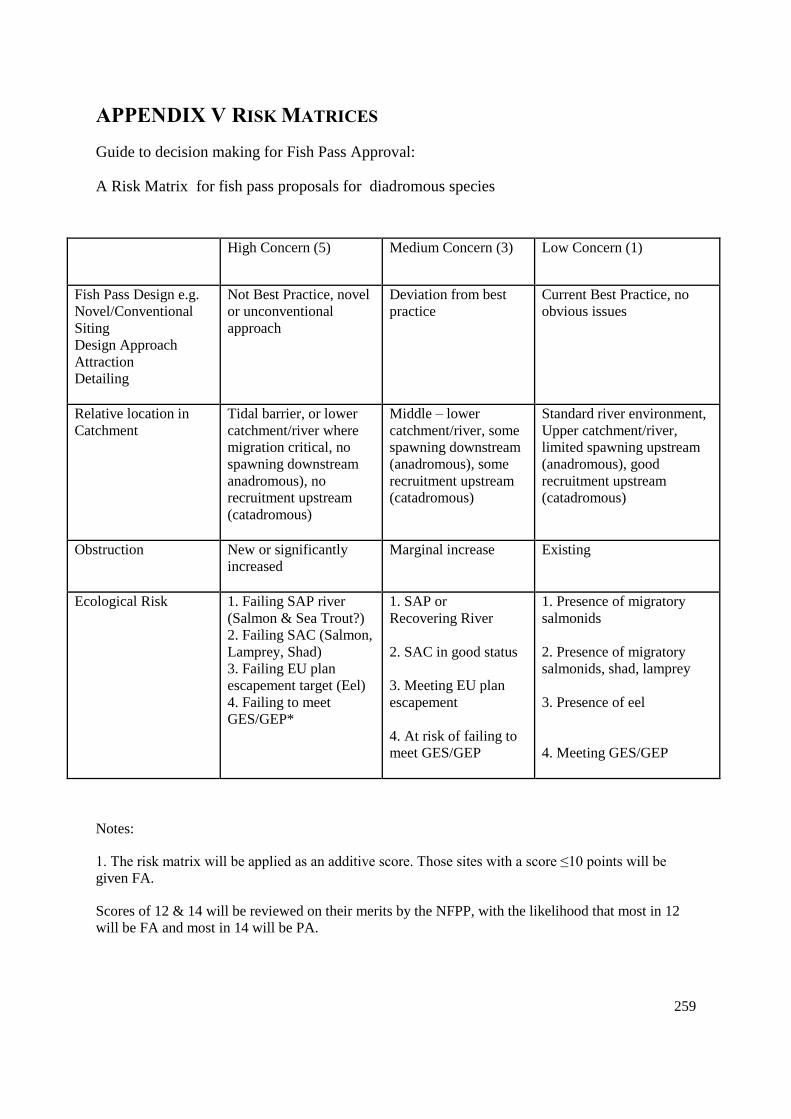
259
APPENDIX V RISK MATRICES
Guide to decision making for Fish Pass Approval:
A Risk Matrix for fish pass proposals for diadromous species
High Concern (5) Medium Concern (3) Low Concern (1)
Fish Pass Design e.g.
Novel/Conventional
Siting
Design Approach
Attraction
Detailing
Not Best Practice, novel
or unconventional
approach
Deviation from best
practice
Current Best Practice, no
obvious issues
Relative location in
Catchment
Tidal barrier, or lower
catchment/river where
migration critical, no
spawning downstream
anadromous), no
recruitment upstream
(catadromous)
Middle – lower
catchment/river, some
spawning downstream
(anadromous), some
recruitment upstream
(catadromous)
Standard river environment,
Upper catchment/river,
limited spawning upstream
(anadromous), good
recruitment upstream
(catadromous)
Obstruction New or significantly
increased
Marginal increase Existing
Ecological Risk 1. Failing SAP river
(Salmon & Sea Trout?)
2. Failing SAC (Salmon,
Lamprey, Shad)
3. Failing EU plan
escapement target (Eel)
4. Failing to meet
GES/GEP*
1. SAP or
Recovering River
2. SAC in good status
3. Meeting EU plan
escapement
4. At risk of failing to
meet GES/GEP
1. Presence of migratory
salmonids
2. Presence of migratory
salmonids, shad, lamprey
3. Presence of eel
4. Meeting GES/GEP
Notes:
1. The risk matrix will be applied as an additive score. Those sites with a score ≤10 points will be
given FA.
Scores of 12 & 14 will be reviewed on their merits by the NFPP, with the likelihood that most in 12
will be FA and most in 14 will be PA.
260
Scores ≥ 16 will be PA.
Any sites scoring as’ Not Best Practice’ will only receive PA at best
2. Failing SAP sites scoring 5 includes ‘At Risk’ and ‘Probably at Risk’ of failing (2013)Management
targets.
Sites scoring 3 include ‘Not at Risk’ and ‘Probably Not at Risk’ of failing to meet (2013)
Management Targets. This category also includes recovering rivers that may be failing SAP targets
but are not mature enough to anyway hope to pass the (future) MT.
3. Please append any comments to the reverse of this sheet.
* In relation to the migratory species present

261
Guide to decision making for Fish Pass Approval:
A Risk Matrix for fishpass proposals for potamodromous species
High Concern (5) Medium Concern (3) Low Concern (1)
Fish Pass Design e.g.
Novel/Conventional
Siting
Design Approach
Attraction
Detailing
Not Best Practice,
novel or
unconventional
approach
Deviation from best
practice
Current Best Practice, no
obvious issues
Relative location in
Catchment
Demonstrably
restricting ecological
status
Prevents altogether
colonisation/re-
colonisation of
substantial suitable
habitat
Prevents adults
reaching significant
spawning areas
Populations
discontinuous
Potentially restricting
ecological status
Colonisation/recolonisation
is restricted & slow
Unlikely to restrict
ecological status
Upper limit of
distribution, limited
availability of habitat
upstream
Limited spawning area
upstream
Populations continuous
Obstruction New or significantly
increased
Marginal increase Existing
Ecological Risk Failing to meet
GES/GEP*
At risk of failing to meet
GES/GEP
Recovering river
Meeting GES/GEP
Notes:
1. The risk matrix will be applied as an additive score. Those sites with a score ≤10 points will be
given FA.
Scores of 12 & 14 will be reviewed on their merits by the NFPP, with the likelihood that most in 12
will be FA and most in 14 will be PA.

262
Scores ≥ 16 will be PA.
Any sites scoring as’ Not Best Practice’ will only receive PA at best.
2. Please append any comments to the reverse of this sheet.
* In relation to the potamadromous species present

Form FP 002: Application for Fish Pass Approval
__________________________________________________________________________________________________________________
263
APPENDIX VI Draft Application For Fish Pass Approval Form

264
Application for fish pass approval
Introduction
Please read through the guidance notes FP003 and the application
form carefully before you fill this form in.
Please contact us if you are unclear about anything in this form. The general
enquiries number is 08708 506 506.
This form is designed to get the information that we require in order to
understand and approve the design and dimensions of a proposed fish
pass design. However, please note that fish pass design is a highly
specialised and technical discipline and you are advised to refer to the
Environment Agency Fish Pass Manual (or other similar publications)
and/or use specialist consultants in the field to help ensure that an
appropriate design and adequate details are provided.
Contents
1 Site details
2 Obstruction details
3 Fish pass details
4 Fish species & period of operation
5 River discharge data and water level information
6 Description of fish pass operation
7 Eel passes
8 Monitoring and maintenance
9 Supporting documentation
1 Site details
1.1 What is the name of the site?
__________________________________________________________________
1.2 National Grid Reference of the site (10 figure)?
__________________________________________________________________
1.3 Environment Agency region and area (If known)
Region____________________________________________________________
Area_____________________________________________________________
1.4 Name of watercourse
__________________________________________________________________
1.5 Watercourse Order or Hierarchy
Please give the watercourse name and then as appropriate each successive river until the primary watercourse reaches the sea
as watercourse/tributary of 1/tributary of 2/……./tributary of n/Sea.

Form FP 002: Application for Fish Pass Approval
__________________________________________________________________________________________________________________
265
__________________________________________________________________
2 Obstruction details
2.1 What is the nature of the obstruction to fish passage that the pass is designed to overcome?
__________________________________________________________________
2.2 What is the purpose of the obstruction?
__________________________________________________________________
2.3 What is the configuration of the obstruction?
__________________________________________________________________
2.4 What is the overall crest length(s) of the obstruction that the pass is located in or beside (m) and what is its (their) invert level
(mAOD)
__________________________________________________________________
2.5 What is the maximum head difference across the structure (m).
__________________________________________________________________
2.6 Who owns the obstruction and river banks?
Title ______________
Forename ____________________________________________________________
Surname ____________________________________________________________

266
Position ____________________________________________________________
Flat/Building Name/Number ____________________________________________________________________
Street ___________________________________________________________________________________
Town ___________________________________________________________________________________
County ___________________________________________________________________________________

Form FP 002: Application for Fish Pass Approval
__________________________________________________________________________________________________________________
267
Postcode __________________________________
Country ______________________________________
Phone __________________________________
Mobile ______________________________________
Fax __________________________________ Email ______________________________________
3 Fish pass design & ownership details
3.1 Who has designed the fish pass
Title ______________
Forename ____________________________________________________________
Surname ____________________________________________________________
Position ____________________________________________________________
Company name _______________________________________________________
Flat/Building Name/Number ____________________________________________________________________
Street ___________________________________________________________________________________
Town ___________________________________________________________________________________
County ___________________________________________________________________________________
Postcode __________________________________
Country ______________________________________
Phone __________________________________
Mobile ______________________________________

268
Fax __________________________________ Email ______________________________________
3.2 Who will own the fish pass?
As in question 2.6
As below
Title ______________
Forename ____________________________________________________________
Surname ____________________________________________________________
Position ____________________________________________________________
Flat/Building Name/Number ____________________________________________________________________
Street ___________________________________________________________________________________
Town ___________________________________________________________________________________
County ___________________________________________________________________________________
Postcode __________________________________
Country ______________________________________
Phone __________________________________
Mobile ______________________________________
Fax __________________________________ Email ______________________________________
3.3 Name of the lead Environment Agency officer involved with this pass, if applicable?
__________________________________________________________________
4 Fish species
4.1 Provide details of species for which the pass is designed. Indicate a size range for each fish species.

269
*List Species in each group
__________________________________________________________________
4.2 Identify any other species present at this site (for which passage would be desirable) and include the size of the fish?
__________________________________________________________________
Species Designed For Range (cms)
Salmon
Sea Trout
Brown Trout
Eels
Shad
Lamprey*
Grayling
Coarse Fish*
Others*

270
4.3 Is there a need for the pass to operate 12 months of the year?
Yes Continue to section 5
No
If you intend to operate over shorter periods that coincide with the relevant species movement patterns, name the species groups (as
above) and state the periods when it is expected to operate for them below:
5 River discharge data and water level information
5.1 Please provide the annual river discharge hydrograph as a graph and/or table showing flow as cubic metres per second
(m3s
–1 ) against percentile exceedance value. Identify the gauging site from which the data originates, and if not at the
structure itself state distance removed up or downstream and describe any interpolation used. If not gauged, state how it
was estimated such as “generated from hydrometric software `Low Flow 2000`”
Annual discharge summary for river given as m3s
-1 to two decimal places:
Species Months of year
%tile exceedence Annual Discharge (m3s
-1)
5
10
50
90
95
ADF*

271
* Annual mean daily flow
5.2 Range of river discharge over which pass is expected to operate
Percentile m3s
–1
Lowest Flow Q
Highest Flow Q
5.3 River water levels above ordinance datum (mAOD) corresponding with the flows identified in the previous question.
Upstream Level Downstream Level Estimated or measured*
Lowest Flow
Highest Flow
* Describe how the were recorded or estimated.
5.4 Is the fish pass for eel only?
Yes (please go to question 8)
No (please go to question 7)
6 Description of fish pass, operating flows, and intended operating periods
Please include plans and sectional elevations of all relevant parts of the pass and adjacent structures. (see guidance)
6.1 Type of fish pass
__________________________________________________________________
6.2 Description of fish pass
__________________________________________________________________
6.3 Describe why the pass was positioned at its proposed location and identify any constraints restricting the
choice of location?
__________________________________________________________________

272
6.4 How is the pass location and operation designed to ensure that fish are attracted to the fish pass across the intended river discharge operating range.
6.5 Describe any operating regime(s) or protocols for those nearby water control structures that may in any way affect operation of the pass.
_________________________________________________________________
6.6 Does the fish pass include a pool pass? Yes No (please go to question 7.10)
6.7 Describe how it is intended that the pool pass will operate to pass fish efficiently and effectively including the changing
hydraulic conditions that will exist within it over the range of river discharge (window of fish migration) when is the pass
is expected to operate.
__________________________________________________________________
6.8 Summarise the operating conditions at the limits of operation in the following table;
* Drop from last pool to prevailing tailwater level
River Discharge
(m3s
–1)
Exceedance Value
(percentile)
Pass
Discharge
(m3s
–1)
Augmentation
flow (if any) (m3s
–1)
Total attraction
flow as % of river
discharge
Pool Numbera
Length and
Width (m)
Min mean
depth (m)b
Max
mean
depth
(m)c
Head
difference
Max (m)b
Head
difference
Min (m)c
P/V Min
(Wm-3
)
P/V Max
(Wm-3
)
1
2
nn
Tailwater*

273
6.9 Does the fish pass include a baffle pass?
Yes
No (please go to question 7.14)
6.10 Describe how it is intended that the baffle pass will operate to pass fish efficiently and effectively including the changing
hydraulic conditions that will exist within it over the range of river discharge (window of fish migration) when is the pass
is expected to operate.
__________________________________________________________________

274
6.11 Give details of the operating conditions at the limits of operation in the following table:
Parameter Flight 1 Flight 2 Flight 3 Flight 4
Upstream Pass Slope
Invert Elevation
(mAOD)
Upstream Pass
Hydraulic Invert
Elevation (mAOD)
Downstream Pass
Slope Invert
Elevation (mAOD)
Downstream Pass
Hydraulic Invert
Elevation (mAOD)
Head Difference (m)
slope
Length slope (m)
Slope %
Head Ha on top
baffle (min)(m)
Head Ha on tail
baffle (min)(m)
Head Ha on top
baffle (max)(m)
Head Ha on tail
baffle (max)(m)
Mean Velocity (min)
Mean Velocity (max)

275
*Ha is the hydraulic head over the invert of the baffle
6.12 Where resting pools are required please summarise details of the operating conditions in the table below:
6.13 For combined passes and passes other than pool passes or baffle passes, please follow the principles outlined above in 7.7
– 7.12 to provide details of the proposal. See guidance notes for description of application requirements.
7 Eel passes
This section is only to be used for passes specifically designed to pass eels and elvers.
7.1 Type of eel pass?
__________________________________________________________________
7.2 Description of eel pass?
__________________________________________________________________
Pool
Numbera
Length
and Width
(m)
Depth (min)
(m)b
Depth
(max)
(m)c
Equivalent
head(min)
(m)d
Equivalent
head(max)
(m)d
P/V Min
(Wm-3
)
P/V Max
(Wm-3
)
1
2
nn
tailwater

276
7.3 For pump feed passes only. Give details of the pump and associated infrastructure?
__________________________________________________________________
7.4 Describe why the proposed pass is planned to be installed at the location indicated and identify any constraints restricting
the choice of location?
__________________________________________________________________
7.5 Describe any operating regime(s) or protocols for nearby water control structures that may in any way affect operation of
the pass.
__________________________________________________________________
7.6 Provide a summary of the operating conditions at the limits of operation in the table below.
8 Monitoring and maintenance
This section to be filled in for all types of pass and intended species
8.1 Outline any proposals for monitoring the hydraulic and biological performance of the pass after construction.
Flight 1 Flight 2
Upstream pass invert elevation (mAOD)
Downstream pass invert elevation (mAOD)
Head difference (m)
Length (m)
Slope %

277
__________________________________________________________________
8.2 Outline the procedures that will be put in place to ensure the structural and operational maintenance of the pass.
__________________________________________________________________

278
9 Supporting documentation
Please include with this application the following:
a map or plan (1:50,000) with this application
the annual river discharge hydrograph
detailed engineering drawings of the existing obstruction and the proposed design for the fish pass.
List Drawings and their reference numbers: __________________________________________________
If available the engineering drawings of the existing obstruction and the proposed design for the fish
pass
If essential documentation has not been provided we will not be able to assess your proposal and all documentation
will be returned without further processing.

279
Application for fish pass approval
Guidance notes
INTRODUCTION
Please read through the guidance notes and the application form
carefully before you fill the form in.
Please contact us if you are unclear about anything in this form. The general
enquiries number is 08708 506 506.
This form is designed to illicit the information that we require in order
to understand and approve the form & dimensions of a proposed fish
pass design. However, please note that fish pass design is a highly
specialised and technical discipline and you are advised to refer to the
Environment Agency Fish Pass Manual (or other similar publications)
and/or use specialist consultants in the field to help ensure that an
appropriate design and adequate details are provided.
Contents
1 Site details
2 Obstruction details
3 Fish pass details
4 Fish species & period of operation
5 River discharge data and water level information
6 Description of fish pass operation
7 Eel passes
8 Monitoring and maintenance
About the form
Fish pass facilities designed to aid the upstream passage of fish are specialised structures. Where they have been
required on rivers inhabited by migratory salmon, sea trout, and eels the form and dimensions of the pass must
be approved by the Environment Agency.
This is so we can ensure that an appropriate type and construction of pass is provided.. We will require pass
designs for other fish species (such as coarse fish) to be compatible with approved status for the same reasons of
consistency and quality and therefore ask for this form to be filled in for all fish passes, regardless of the
intended species.
Q1 Site details
We need to be able to easily identify the location of the proposed fish pass, please provide:
Site name - Provide name of site including alternative local names (if any).
Site location - National Grid Reference (10 figure).
Environment Agency Region and Area - Include the Environment Agency Region and area, if known
Name of watercourse
Stream order or hierarchy –

280
Q2 Obstruction details
2.1 Nature of obstruction
Give a description of the type of obstruction, for example: vertical weir, sloping weir, stepped weir, weir &
control structures, control structures only (mixed), sluices, radial gates, dam, estuary barrage, tidal exclusion,
bridge footings, ford, culvert, natural falls, other (please specify).
2.2 Purpose of obstruction
Give a description of the purpose of obstruction, for example: navigation, abstraction, hydrometric/gauging
weir, bed/bank stabilisation, fish counter, fishing weir, flood defence, hydroelectric, milling, recreational,
transport crossing, other (please specify)
2.3 Configuration of obstruction
Provide a description and plan at 1:2500 or 1:10,000 showing the general site layout including any relevant
control structures, associated channel bifurcations or braiding. Where there are multiple channels at an
obstruction describe how the flows are currently distributed.
2.4 Length of the crest of the structure(s) that the pass is beside
Provide the overall length of the existing structure, including separate details for fixed crest overfall and other
water control structures. Please also ensure that the inverts of the structure(s) are noted on the plans
accompanying this application.
2.5 Maximum head difference (m)
State the maximum head drop expected between upstream and downstream water levels. The maximum head
difference at a structure will normally occur at low flow, but this may not always be the case. Please state at
what exceedance flow the maximum head drop is expected, such as Q95. If the maximum head drop does not
occur at low flow please explain how and why it occurs at a different flow.
Q3 Fish pass details
3.3 Lead Environment Agency Officer
If it is a non-Environment Agency pass please give the name and location of any Environment Agency Officer
who has been consulted during the design process. If it is an Environment Agency pass development please
provide details of the Officer leading the project including name, office base, and contact details.
4 Fish species & period of operation
4.1 Species

281
Please indicate for what species the pass is designed to operate.. For the species groups asterisked please list the
individual species in those groups under separate headings, for example, Lamprey = Sea lamprey, River lamprey
Brook lamprey; Coarse fish = Barbel, Chub, Dace, ………; Others = Bullhead, minnow, ………
4.3 Period of operation
If expected to work for all species or over all 12 months enter ALL. Otherwise, please use the species groups in
4.1, expand the number of boxes as necessary, and enter details separately.
5 River discharge and water level information
5.1 River discharge
River discharge exceedance data can be obtained by Environment Agency Hydrometric Officers (a charge may
be made). For example, Q95 is a low discharge exceeded for 95% of the time, Q10 is a higher discharge exceeded
for 10% of the time.
5.2 Range of river flow
Where specific widows of migration are known please use these, recording them separately for each target group
of species (as per 5.1 above). Where windows of migration are not specifically known for the site, then it is
expected that the pass will operate over the following ranges: Q90 to Q10 for salmon, Q95 to Q10 for sea trout, Q95
to Q20 for coarse fish, and Q99 to Q70 for eels.
5.3 River water levels
Please indicate how these levels have been established. Were they monitored over a range of flows, measured at
specific flows, or estimated. If the latter describe the methodology used. You may need to take account of
differences during different seasons of the year for example weed growth in summer months may cause water
levels to be higher than in winter months.
Where different flow migration widows and water levels apply to different species groups it will be useful to
give these separately, and also to indicate them on the drawings supplied.
6 Description of fish pass, operating flows, and intended operating periods
The details provided in this section must accurately describe the form & dimensions of the pass, and how the
fish pass is intended to operate effectively over the range of river flows (migration window) when the target
species are expected to be migrating.
Plans and sectional elevations
Include plans and sectional elevations of all relevant parts of the pass and adjacent structures. The levels of all
relevant crests, inverts of elements of the pass, and the upstream and downstream water levels under the range of
river water levels over which the pass is expected to operate should be marked on the drawing using Ordnance
Survey datum. Should a local datum be used please identify the location and height of the temporary bench mark
used. Three copies of the final plans will be needed for Approval to be issued: one each for the owner, the
Environment Agency Area file, and the Environment Agency National file. Please list the drawing number(s)
including revision number(s) and date of revision (if any).

282
6.1 Type of pass
For example, fish pass types include: Pool & Traverse, Pool & Orifice, Pre-barrage(s), Vertical Slot, Deep
Notch & Orifice, V Notch Weir , Plane Baffle Denil, Alaskan A Denil, Larinier (Super-active Baffle), Chevron
Bottom Baffle, Chevron Side Baffle, Hurn Type Baffle, Low Cost Baffle, Bristle Fish & Canoe, Combination of
these (Specify), Other (please specify).
6.2 Description of pass
Please describe very briefly the general layout of the pass for example single flight of Plane Baffle Denil, two
flights of Larinier pass with rest pool, x pool Vertical Slot pass, x pool Pool & Traverse pass, Alaskan A Denil
with pre-barrages.
6.3 Position of pass
Please describe where the downstream entrance of the pass is in relation to the toe of the obstruction and why it
is located there. Typically the location of the downstream entrance is critical for a pass for upstream migrants.
For example, it may be the most upstream location, it may be where fish are observed to collect, or else where
tracking studies have identified that they approach the obstruction. The opposite will be the case for downstream
passes. If it is relevant describe the relationship or juxtaposition of the pass downstream entrance with the
discharge from a hydropower station.
6.4 Pass location and operation design
The ability to attract fish in to the fish pass entrance is absolutely critical to efficient fish pass performance.
Please describe how the pass has been designed and located in order to attract fish efficiently in to the pass. This
will include, for example, location of the pass entrance, relative proportion of attraction flow compared with
river discharge, hydrodynamics including exit jet velocity and direction, any augmentation flows, any
operational procedures used to increase attraction, and how these features may change over the expected range
in river discharge & water levels when the pass is expected to operate effectively. Describe any changes
proposed to flow distributions in any braided channels at the site, including identifying any depleted reaches.
Information on critical breakpoints in flow distribution should be provided in the table e.g. Q95, Qmean, Q10, Qmax
turbine discharge.
6.5 Effect of other control structures on operation of the pass
Spills of water at or from other parts of the structure, and particularly varying ones from water control structures
may alter the performance of the pass by altering the water level regime, flows in the pass, and relative attraction
of the pass. For example, manipulation and sequence of opening of sluice gates (undershot & overshot), separate
flood discharge channel arrangements, abstractions, hydropower operating regimes, or extraneous discharges.

283
6.7 Details of pool passes
This section, with the aid of the drawings, should demonstrate how the pool pass is designed to meet the
guidelines laid out for pool passes in the Environment Agency Fish Pass Manual
For Pool Passes the following details must appear either in the detailed drawings, or else be separately
described:
Elevations and dimensions of all relevant inlet or outlet channels and control structures at the site that
are likely to affect operation of the pass e.g. adjacent weir crest, inverts(s) of water control structures
etc
Elevations of side walls and the bases of pools
Elevations and dimensions of all overfalls, notches, orifices and sills
Thickness of traverses in notches or on overfalls
Length and width of all pools
Expected water levels in pools at minimum and maximum range of intended operation
Geometry of vertical slots if present
Dimensions and elevations of debris shielding arrangements, including the free gaps between bars if
any are fitted
Volumetric power dissipation (power density) values in the pools at minimum and maximum range of
intended operation given as Wm-3
(see table below)
Details of any ancillary structures such as traps or counters in so far as they may affect pass
characteristics or operation
Details of any coverings or lighting arrangements
.
6.8 Operating conditions for pool passes
This section summarises the hydraulic conditions expected in the fish pass at the limits of its intended (river
discharge) operation
Power dissipation per unit volume (power density) is a measure of turbulence in the pools, it may be calculated
using:

284
P/V (Wm-3
) = (9810 x Q x DH) / (L x W x Dm ) (1)
Where:
Q = flow m3s
-1
DH = difference in head between pools (m)
L = length of pool (m)
W = width of pool (m)
Dm = mean depth of pool (m)
The table should be filled in using the following conventions:
a Pools numbered from upstream to downstream
Pools may be aggregated together where the various parameters are similar e.g. 2+6, 2-6
b Depth occurring at lowest discharge
c Depth occurring at highest discharge
6.10 Details of baffle passes
This section, with the aid of the drawings, should demonstrate how the baffle pass is designed to meet the
guidelines laid out for baffle passes in the Environment Agency Fish Pass Manual
For Baffle Passes the following details must appear either in the detailed drawings, or else be separately
described:
Elevations and dimensions of all relevant inlet or outlet channels and control structures at the site that
are likely to affect operation of the pass e.g. adjacent weir crest, invert(s) of water control structures etc
Elevations of side walls
Elevations of upstream & downstream ends of the slopes of each flight
Elevations of the baffle inverts at the upstream & downstream ends of each flight
Elevations of inlet & outlet channels
Length of each flight (m)
Slope of each flight (%)
Baffle height, thickness and design geometry including spacing
Expected water levels at the upstream & downstream ends of each flight at the minimum and maximum
range of intended operation
Elevations of the side walls and bases of any resting pools
Length and width of any resting pools

285
Volumetric power dissipation (power density) values in any resting pools at minimum and maximum
range of intended operation as Wm-3
(see table below)
Dimensions and elevations of debris shielding arrangements, including the free gaps between bars if
any are fitted
Details of any ancillary structures such as traps or counters in so far as they may affect pass
characteristics or operation
Details of any coverings or lighting arrangements
6.11 Operating conditions for baffle passes
This section summarises the hydraulic conditions expected in the fish pass at the limits of its intended (river
discharge) operation
6.12 Resting pools for baffle passes
Power dissipation per unit volume (power density) is a measure of turbulence in the pools, it may be
calculated using:
P/V (Wm-3
) = (9810 x Q x DH) / ( L x W x Dm) (1)
Where:
Q = flow m3s
-1
DH = difference in head between pools (m)
L = length of pool (m)
W = width of pool (m)
Dm = mean depth of pool (m)
The table should be filled in using the following conventions:
a Pools numbered from upstream to downstream
b Depth occurring in pool at lowest discharge
c Depth occurring in pool at highest discharge
d An approximation of the difference in head (DH) to substitute in Equation (1) above for baffle passes
can be calculated using:
DH V2/2g
286
Where
DH = an equivalent head in (m)
V = mean velocity in the pass
g = acceleration due to gravity (9.81ms-2
)
6.13 Other fish passes
This section, with the aid of the drawings, should demonstrate how any other form of pass other than a pool pass
or baffle pass is designed to meet the guidelines laid out for that type of pass in the Environment Agency Fish
Pass Manual (Version 1.1 February 2004).
All details relevant to describing the efficient & effective operation of the pass should be provided. These may,
where relevant, follow the outlines provided for pool and baffle passes. They should include for example:
Elevations and dimensions of all relevant inlet or outlet channels and structures that are likely to affect operation
of the pass.
Relevant hydraulic conditions in the pass including flows, velocities, head drops, pool sizes, and volumetric
power dissipation (power density) values as Wm-3
across the range of river discharge when the pass is expected
to operate.
For composite Baffle and Pool & Traverse passes please also use the principles outlined separately above for
these types of pass.
7 Eel passes
The details provided in this section must accurately describe the form & dimensions of the pass, and how the
fish pass is intended to operate effectively over the range of river flows (migration window) when the target
species are expected to be migrating.
7.1 Type of pass
Please identify the type of pass by selecting appropriate features from the following list of descriptors:
Open or Enclosed; Gravity Fed or Pump Fed; Bristle Ramp, Boss Ramp, Other Ramp (please identify media);
With Lateral slope or Without Lateral Slope; Fabricated Channel e.g. GRP, Aluminium, Steel etc or In-situ
Channel e.g. cast in concrete; Bristle Media on sidewall; Tidal Flap Modification; Eel Lift; Other (specify);
With Monitoring Facility or Without Monitoring Facility.
7.2 Description

287
Please provide a description of the pass/easement through inclusion of a photograph, drawings or written
description, manufacturer and model number, specification of substrate including type & spacing. The entrance
and exit of the pass are key areas in respect to fish finding and accessing the pass, and exiting safely. Please state
the number of flights and rest areas, and what, if any, trapping or other monitoring facilities are provided.
7.3 Pump fed passes
Please provide details of the following: Pump Capacity (litres/minute) at the target head level; details of the
pump installation (drawings) to showing the pump in relation to the channel and the eel pass; show any
screening or protection from debris and the facilities for cleaning/maintenance. Indicate how water is fed into
the head of the pass and any flow-splitting arrangements (to upstream ramp/trap and downstream ramp. State
how the pump will be powered e.g. mains voltage, battery array, solar power, wind power, or other.
7.4 Location details
The ability for eel to find the fish pass entrance is absolutely critical to efficient eel pass performance. Please
describe how the pass has been located in order to for eel to efficiently find the pass.
7.5 Operating regimes
Spills of water at or from other parts of the structure, and particularly varying ones from water control structures
may alter the performance of the pass by altering the water level regime, flows in the pass, or the areas that eel
may congregate in. For example, manipulation and sequence of opening of sluice gates, separate flood discharge
channel arrangements, abstractions or extraneous discharges etc).
7.6 Operating conditions
This section summarises the hydraulic conditions expected in the eel pass at the limits of its intended (river
discharge) operation.
8 Monitoring and maintenance
8.1 Hydraulic and biological performance
A full monitoring programme would demonstrate that the fish pass is functioning as anticipated both
hydraulically and biologically. The use of gauge boards upstream & downstream of the pass to help establish
that the pass is operating within the expected range of head levels is highly recommended as part of the physical
monitoring of the pass. Biological monitoring should aim to demonstrate that the target fish species use the pass
effectively and efficiently.
8.2 Structural and operational maintenance
It is an offence not to maintain the pass in an effective and efficient state. How often will the structural integrity
of the pass be checked, and by whom. How often will the pass be checked to ensure that it is operating correctly
and is not compromised by debris collection, and who will be responsible.

288
APPENDIX VII Typical List Of requirements For A Feasibility
Study
The contents of a feasibility study might look like the following:
Introduction
The Brief
The Site
Fish Species
Data Sources
River Flows
Consultations
Existing Obstruction
History
Type & Construction (including plans)
Use & Operation
Visual Inspection & Condition
External Influences
Hydraulic Assessment
Constraints
Topography of Existing Obstruction

289
Structural Condition of Existing Obstruction
Upstream & Downstream Water Levels
Access & Working Environment
Ownership
Conservation Matters
Planning Matters
Utilities
Feasibility Options
Required Operating Range
Option Types
Assessment of Options (1 to nn)
Recommended Option(s)
Budget Cost Estimate(s)
Outstanding & Miscellaneous Issues
Conclusions
Appendices

290
APPENDIX VIII Examples of Cost Benefit Analysis
IX.A Cost benefit analysis for the fish pass construction on the Garth Dulas, a tributary
of the R. Irfon.
Tech. Memo: SE/EAU/96/11. M. Clyde. Environmental Appraisal Unit (S.E.), National Rivers
Authority - Welsh Region, St. Mellons, Cardiff. March 1996.
1. Introduction
The NRA in conjunction with the Wye Salmon Fishery Owners Association (WSFOA) are
considering ways of increasing the spawning area available to migratory salmonids, particularly in the
Upper Wye. These include:
i) gravel clearing/raking of impacted spawning areas
ii) removal of temporary blockages
iii) alteration of natural permanent barriers
iv) removal of man-made barriers/construction of fish passes.
The Garth Dulas is one of the main tributaries of the R. Irfon, a sub-catchment of the Upper Wye. It
enters the Irfon at SN 955494, 11km upstream of the Irfon/Wye confluence. The Upper reaches of the
Irfon are impacted by acidification, a problem not apparent in the Garth Dulas.
Access of migratory salmonids to the upper Garth Dulas is restricted by a concrete weir at SN
945516, 4km from the confluence with the R. Irfon. Construction of an effective fish pass would
increase the accessible stream area by 51,750m2.
2. Objectives
The aims of this simple cost benefit analysis were to assess the benefits, in terms of salmon smolt
yield and adult return, of constructing an efficient fish pass on the Garth Dulas, and the costs
associated with this undertaking.
3. Methods

291
Historical fisheries, water quality and biological data for the Garth Dulas were collated to assess the
general state of the catchment.
3.1 Water Quality
Water quality data for the period 1990-1995 were retrieved for the only sample point on the Garth
Dulas (SN 949494), downstream of the weir.
3.2 Fisheries
2 sites on the Garth Dulas have been routinely electrofished as part of the RJSMP since 1985. One site
has been fished quantitatively and the other semi-quantitatively. Both are below the weir.
A third site on the Gwynfel, a tributary of the Dulas above the obstruction has been semi-
quantitatively surveyed since 1991.
3.3 Biology
One site on the Garth Dulas below the weir has been surveyed in 1991, 1992 and 1995 as part of the
General Quality Assessment (GQA) programme/River Quality Survey (RQS).
3.4 Habitat
An extensive habitat assessment was undertaken by NRA bailiffs following the methodology listed in
Betts et al (1994).
The method entailed a simple mapping exercise, dividing the river and tributaries into sections
depending on their suitability as salmonid spawning/rearing habitat. Habitat was classed as either:
i) non-salmonid,
ii) moderate salmon rearing or
iii) good salmon rearing habitat.
The good habitat consisted of glides/riffles with gravel as the main substrate and moderate habitat
mainly cobbles. Bedrock/deeper water formed the majority of non-salmonid rearing habitat.
Width measurements were taken in each section to allow an estimation of the area of each habitat
type.

292
3.5 Smolt production
The river area available for salmonid spawning/rearing above the weir was calculated from the habitat
mapping undertaken by the bailiffs. Areas of non-salmonid habitat were not included in the smolt
production estimates.
In areas of good juvenile habitat a smolt production output of 5 per 100m2 (Symons, 1979) was
assumed and in areas of moderate juvenile habitat a lower output of 3 per 100m2 was assumed. Age
of fish at smoltification was not considered in the smolt output estimates.
95% mortality of wild smolts was used in the estimate with a rod recapture rate of returning adults of
20%. Again the age of fish on return to freshwater
has not been taken into account in calculating the potential adult return rate/economic benefit.
The value of increased smolt production from the Garth Dulas was calculated solely on the potential
increase in the annual salmon rod catch with 2 different values used to calculate the potential
economic benefit:
i) Harris and Stokes (1994) estimated the value of a salmon to the R. Wye fishery to be £3000. Harris
and Stokes are Commercial Property Specialists based in Hereford.
ii) Radford and Hatcher (1991) estimated the per capita value of each salmon to the average annual
rod catch of a Welsh river to be £5647.

293
4. Results
4.1 Water quality
Summary of data (1990-1995) from sample site on the Garth Dulas.
Determinand Number of
samples
Minimum Maximum Mean Standard
Deviation
pH 78 5.9 7.8 6.9 0.33
Conductivity 15 58 104 78 13.6
Temperature 73 0.6 20 9 4.2
Diss. Oxygen 73 75 111 95 6.7
BOD mg/l 73 0.4 3.8 1.1 0.6
NH4 mg/l 73 0.01 0.17 0.02 0.02
TON mg/l 12 0.24 1.1 0.62 0.33
Alk4.5 mg/l 27 6.9 20.6 11.8 3.5
Total Hard. 54 9.5 76.3 23.6 9.7
Total Zn mg/l 51 <2 72 11.2 10.8
Diss. Mg mg/l 54 1.1 4.9 1.9 0.5
Diss. Ca mg/l 54 1.8 22.5 6.4 3.2
Diss. Al mg/l 16 0.004 0.22 0.06 0.05
There was no evidence from the routine water quality data available that low pH events occur on the
Garth Dulas, or that spawning of migratory salmonids is limited by the prevailing water quality. This
is unlike the situation in the upper reaches of the Irfon that are impacted by acidification due to
extensive afforestation, exacerbated by the poor buffering capacity of the underlying substrata. The
upper Garth Dulas is not heavily afforested.
The water quality data is however from a site on the lower Dulas.
4.2 Fisheries
RJSMP results for sites on the Garth Dulas and its tributary the Gwynfel

294
RJSMP Site 8, SN 947497, Garth. Quantitative survey, downstream of weir.
Year Salmon
0+
Salmon
>0+
RJSMP
Class
Trout
0+
Trout
>0+
RJSMP
Class
1985 121.4 1.6 A - - D
1986 300 16.1 A - 0.9 C
1987 187.3 3.7 A - 3 C
1988 162.6 12.8 A 0.5 1.3 D
1989 333.8 22.5 A 10.4 5.8 C
1990 319.6 13.2 A - 1.2 D
1991 262.6 10.5 A 1.9 - D
1992 301.6 2.3 B 0.6 0.6 D
1993 79.9 2.6 B - - E
1994 319.6 4 B 2 0.8 D
10 yr ave 238.8 8.9 A 1.5 1.4 D

295
RJSMP Site 44, SN 946514, Semi-quantitative survey, downstream of weir.
Year Salmon
0+
Salmon
>0+
RJSMP
Class
Trout
0+
Trout
>0+
RJSMP
Class
1985 152.4 3.2 A - - D
1986 22.3 2.3 B - - D
1987 69.2 3.2 A - 0.6 C
1988 70.3 0.8 B 7.2 0.8 D
1989 41.7 2.1 B - 0.5 D
1990 109.9 2.1 B - - E
1991 - - - - - -
1992 131.3 1.2 B - - E
1993 72.4 2.9 A O.4 - D
1994 85.4 1.8 B 1.8 0.7 D
10 yr ave 83.9 1.9 B 1 0.3 D

296
RJSMP Site 44a, SN 930538, Nant Gwynfel. Semi-quant survey, upstream of weir.
Year Salmon
0+
Salmon
>0+
RJSMP
Class
Trout
0+
Trout
>0+
RJSMP
Class
1991 - - E - 15.4 C
1992 - - E 16.5 9 B
1993 - - E 9.2 21.1 B
1994 - - E 3.4 23.2 B
4 yr ave 7.3 17.2 B
4.3 Biology
Biological quality results for sample site on the Garth Dulas downstream of weir (from GQA/RQS
surveys)
Year/sample Season Invertebrate
BMWP Score
Diversity Class
1990 Spring 150 A
1990 Autumn 181 A
1992 Spring 140 B
1992 Summer 166 A
1995 Spring 139 B
1995 Autumn 135 B

297
4.4 Habitat and smolt production estimates
River Length Width Area Habitat m2 Est Smolt Number Number
Section (m) (m) Total Good Mod Poor Prod (100 m2) Smolts Adults
Dulas A 1500 12 18000 18000 - - 5 900 45
Dulas B 1500 11 16500 16500 - - 5 825 41.25
Dulas C 250 6 1500 - - 1500 - 0 0
Dulas D 250 8 2000 - 2000 - 3 60 3
Dulas E 500 5 2500 - - 2500 - 0 0
Dulas F 1000 4.5 4500 - 4500 - 3 135 6.75
Gwynfel G 1000 3 3000 - - 3000 - 0 0
Gwynfel H 1500 2.5 3750 - 3750 - 3 113 5.65
Total 51750 34500 10250 7000 2033 102
Assuming 20% of returning adults caught by anglers 20
Therefore number of adults using pass 82
Increased value to Wye fishery according to Harris & Stokes, 1994: £60,000
Increased value according to Radford & Hatcher, 1991: £112,940
5. Discussion
The water quality and biological data available is restricted to the lower Garth Dulas and is therefore
limited in terms of assessing the status of the upper reaches. However the current fisheries data
classifies the juvenile salmon populations as 'good' at sites below the weir, and although juvenile
salmon are absent at the site above the weir the juvenile trout population is classed as 'good'.
The water and biological quality of the Garth Dulas is suitable for migratory salmonids as neither
appears to limit the successful spawning and rearing of juvenile salmonids in the lower catchment.
298
Juvenile salmon densities at sites below the weir have consistently been amongst the highest recorded
annually on the Wye. Given these present densities it is possible that the smolt output in parts of the
catchment above the weir could exceed 5 smolts 100m2, with a resulting potential increase in the
number of returning adults.
Apart from the economic value, other benefits would result from opening up the upper Garth Dulas to
migratory salmonids. These include:
i) increase in good quality spawning/juvenile habitat
ii) increase in smolt production
iii) increase in number of returning adults with a subsequent increase in spawning potential.
However offset against the benefits are costs/problems which need to be considered if a fish pass is
constructed.
i) the costs of building a fish pass. These are currently estimated at £30,000 (pers com J. Gregory).
ii) ongoing maintenance of the fish pass structure i.e to keep the structure free of riverborne debris
and functioning efficiently
iii) enforcement requirements to cover the extended spawning area available
iv) monitoring to assess fish pass efficiency, either a count of returning adult spawners or juvenile
survey to estimate spawning success and juvenile survival.
v) there may be a requirement to initially stock the area above the weir to prime the catchment and
boost the salmon populations whilst natural regeneration of returning adults occurs.
6. Conclusions
1. The Garth Dulas is of suitable quality to support juvenile salmonids in the area below the weir and
the fisheries data for the area above the weir falls within the 'good' category so salmonid spawning
and survival there does not appear to be impacted by the prevailing water quality.
2. 51,750m2 of river area would become available with the capacity to produce 2033 smolts.
3. An increase in rod catch produced by the added smolt yield could increase the value of the salmon
fishery to the owners by £60,000 (Harris & Stokes, 1994) or £112,940 (Radford & Hatcher, 1991).
4. A fish pass would open up good quality spawning area with the potential to boost the numbers of
adult salmon returning to the Wye to spawn.
IX.B Retrospective evaluation of Conwy Falls fish pass
299
SELECTION OF FISHPASS OPTIONS
Nigel Milner and Eilis Power
Environment Agency, Ffordd Penlan, Parc Menai, Gwynedd
LL57 4BP
Summary
Evaluation of fishpass options requires their economic costs and benefits to be assessed.
However, the benefits of fishpasses (and many other fisheries management options) are
difficult to assess because of errors in predictions of the biological consequences and in the
estimation of their economic value. This paper offers an approach to incorporate this
uncertainty into a fishpass evaluation, using the Conwy Falls fishpass, North Wales, as an
example. The basis of the method is that the range of likely values, derived using best
judgement where poor data restrict formal statistics, is used to construct a probability
distribution that describes the probability of the outcome, expressed here as Net Present
Value. This is considered to be more helpful to managers than a single benefit-cost ratio
value. The Conwy scheme is shown to be cost-effective, principally because of pump-priming
stocking, which brought benefits forward by several years. The assumptions behind the
method are briefly discussed and areas for further work identified.
1. INTRODUCTION
Fishpasses can be very expensive to build and maintain. It is therefore essential that the best
design is used and that the decision on whether or not to build is based on the best available
information.
Cost-benefit analysis of fishpasses is often a simple comparison between some discounted
value of returning fish versus construction and maintenance costs. Such analysis is probably
acceptable for many assessments, but gives no insight into the likely outcomes or risks
involved and as costs increase so too do the risks associated with failure.
Not only are the stakes higher with more expensive schemes, but their chances of working
effectively and realising their investment may be more complex to determine because of, for
example, problems over efficiency of attraction velocities, flow control systems etc.
Moreover, larger schemes may have wider implications for other users of the river, with
associated values that are sometimes even more difficult to estimate than fisheries benefits.

300
Fishpass benefits are normally based on the fishery value of predicted catch increases. This
introduces two problems; firstly the considerable difficulty in predicting future returns of
fish, and secondly the attribution of economic value to these fish, as well as the evalaution of
a host of other benefits that have no directly measurable economic value.
In the face of so much uncertainty how can we be sure that a correct decision has been taken
over selecting either a scheme option or whether to build at all? We can never be certain of
course, but there are ways to ensure that the full range of information has been evaluated and
presented to managers in ways that facilitate decisions.
There is at present little experience of such analysis in the Agency, although methods for
benefit - cost analysis methods have recently been developed for water quality improvement
schemes (Environment Agency, Benefit Assessment Manual). This paper sets out some
principles and approaches that might be useful, and is intended as a catalyst for further
thought rather than a recipe of procedures. The following is from the salmonid management
perspective, using the Conwy falls fishpass in North Wales as an example, but the principles
should apply to other species and to other types of schemes.
2. RETROSPECTIVE EVALUATION OF CONWY FALLS FISHPASS
2.1 General description
The Conwy Falls scheme was enabled by a Welsh Office grant as mitigation for the A55
Conwy estuary-crossing scheme, with further contributions from the National Rivers
Authority. The decision to build was made after review of other options, including hatchery
and trapping and trucking, and estimation of the fishery benefits based on predicted catches
(not translated into monetary value). The scheme would open up an additional 40% of wetted
rearing area for salmon and sea trout (Fig 1), estimated to increase smolt output by at least
18%.
An initial proposal was for a pool and traverse pass up the face of the falls on the sites of a
previous, but never-functioning, pass built in the last century. This was rejected on visual
grounds because the sight is a noted tourist attraction. The option of tunnelling around the
falls was then considered and an initial proposal was rejected on cost grounds (~ £1m).
A cheaper tunnel design, which later won the British Construction Industry (Small Projects)
Design Award was devised by Donaldsons Associates. The site is situated in a steep,
torrential gorge where the Conwy has an ADF of 8 cumecs. The pass comprises 25 pools
spanning a 12m elevation. Three penstocks control exits and regulated flows through the pass
to a nearly constant 2 cumecs. Flow was a particular issue because it was essential to protect
the flow over Conwy Falls as an important visual amenity and the pass closes at flows below
the 95%ile.
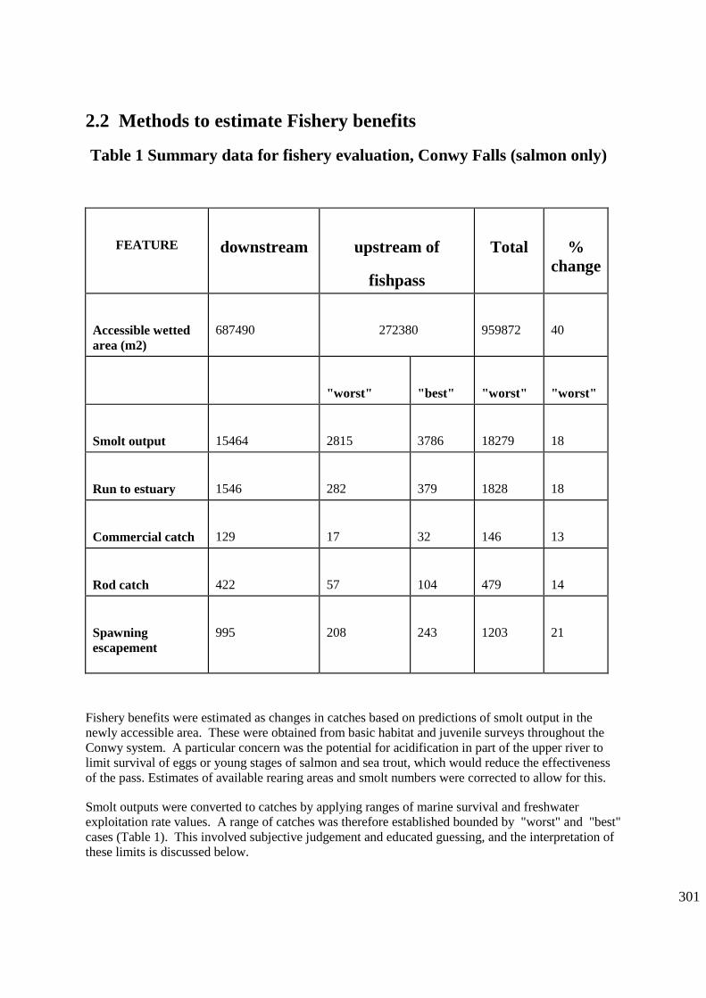
301
2.2 Methods to estimate Fishery benefits
Table 1 Summary data for fishery evaluation, Conwy Falls (salmon only)
FEATURE
downstream
upstream of
fishpass
Total
%
change
Accessible wetted
area (m2)
687490
272380
959872
40
"worst"
"best"
"worst"
"worst"
Smolt output
15464
2815
3786
18279
18
Run to estuary
1546
282
379
1828
18
Commercial catch
129
17
32
146
13
Rod catch
422
57
104
479
14
Spawning
escapement
995
208
243
1203
21
Fishery benefits were estimated as changes in catches based on predictions of smolt output in the
newly accessible area. These were obtained from basic habitat and juvenile surveys throughout the
Conwy system. A particular concern was the potential for acidification in part of the upper river to
limit survival of eggs or young stages of salmon and sea trout, which would reduce the effectiveness
of the pass. Estimates of available rearing areas and smolt numbers were corrected to allow for this.
Smolt outputs were converted to catches by applying ranges of marine survival and freshwater
exploitation rate values. A range of catches was therefore established bounded by "worst" and "best"
cases (Table 1). This involved subjective judgement and educated guessing, and the interpretation of
these limits is discussed below.

302
2.3 Economic Assessment
When undertaking a monetary appraisal all of the values used should be adjusted to current prices,
that is the price level pertaining to the year when the appraisal is carried out (in this case 1991/2).
This is done by applying an adjustment factor (being the difference between current and original
Retail Price Index) to the raw values. The largest correction required is the adjustment for discount
rate to give Present Values (PV) for each item of cost and benefit (see Agency Benefits manual for a
full explanation). Two options for assessment are then possible.
1) Benefit-cost ratio (BCR).
BCR = PVbenefits / PVcosts
A positive value normally signifies a viable scheme. BCRs are used to compare between different
schemes faced with a capital constraint.
2) Net Present Benefit (NPV)
NPV = PVbenefits - PV costs
This describes the value level of benefit, allows assessment of a single or multiple schemes and
provides a means to compare non-monetary benefits.
2.4 Estimation of Net Present Values for Conwy falls fishpass
Net Present Values which were initially calculated over two time periods, 25 and 100yrs, and for two
scenarios:
A)Natural colonisation, without stocking, (with two alternative colonisation models)
B) Colonisation artificially boosted by stocking
In both cases the worst case predicted rod catch of 57 fish (Table1 ) was initially used and the costs
and benefits have been referenced to the first year of construction (year 1). Fishpass construction
costs were phased over three years as follows:
year 1 (1992) £155,000
year 2 (1993) £313,000
year 3 (1994) £32,000
In both scenarios annual running costs, made up of maintenance, counter use and post scheme
monitoring, are assumed to be £14,000. The calculations are made for salmon only, but sea trout are

303
also expected to use the pass. NPVs for salmon were multiplied by 1.5 to allow for an assumed equal
number of sea trout having half the fishery value of salmon.
Benefits have been assumed here to comprise two main components:
Fishery capital value. This is a capital benefit to the fishery owners only. A value of £6,000 per
rod caught fish has been assumed for illustrative purposes (Radford and Hatcher, 1991).
Revenue income This represents an annuity benefit to the economy (the geographical allocation
of this is complex matter and is not relevant to the present calculations). A value of £1,000 is
assumed here (Humphreys and Partners, 1991)
Benefits were calculated with the following assumptions.
Scenario A1:
spawners first use pass in year 4 (first clear year after construction)
smolts are all 2 yr old and adult salmon are all 2 sea winter
spawners increase linearly (Fig 2) from year 9 up to saturation (maximum equivalent to 57 rod
caught fish Table 1) after 10 years
the predicted rod catches (Table 1) are realised without error
Scenario A2:
As A1, but assume that stock (and rod catch) increase exponentially (Fig...) between year 9 and
year 25
Scenario B:
stocking of fry begins in year -4 (8 years before the pass opens to spawners)
stocking costs are based on standard unit production rates (based on fed fry unit cost of £0.3) and
do not assume that a hatchery is purpose built
stocking level is assumed to ensure that saturation escapement is possible in the first year of pass
operation
the predicted rod catches from the saturation spawning return in year 9 (57 fish)
benefits exclude the rod catches derived from fry stocked before returns from natural spawning
began (in year 9)
NB the value of fish derived from the priming stocking, but caught before the pass opens, is
included in these calculations. For illustrative purposes, survival of fed fry to adult returning to
the river was assumed to be 0.001. No capital value was attributed to these fish, because of the
short time they were present, but annual income @£1k per fish (see above) was counted as
benefit.
The one-off capital benefit (E) arising from increased value of the fishery, was converted
to Present Day Value (PV) in 1993 by:-

304
PV(E) = E x (1 + r)-n
(where r = discount rate (currently 6%) and n = number of years)
Construction capital costs were similarly adjusted.
The annual "income"(C) to economy was converted to PV by:-
PV(C) = C x [1 - (1 + r)-n
] / r
Annual maintenance and monitoring annual costs were similarly adjusted.
In summary, the costs and benefits are:
COSTS (£)
1. Construction yrs 1992-4.........................................500k (capital)
2. Maintenance ...........................................................10k (pa)
3. Monitoring.................................................................4k (pa)
4. Stocking .......................................................range 2-45k (pa)
BENEFITS (£)
1. Capital fisheries value..................................................6k (per rod caught fish) (capital)
2. Annual income to local economy.................................1k (per rod caught fish) (pa)
3. value of net catch........................................................£25/fish
4. value of rod-caught fish, derived from stocking, prior to pass opening (variable pa)
Note that the correction of PV to NPV can be made using the above equations or by reference to most
economics textbooks or to the Agency's Benefit Assessment manual, where tables give correction
factors. Use of the equations allows trials with varying interest rate or time horizon.
2.5 The effect of assumptions on NPV
Effect of stocking
The two alternative scenarios, natural colonisation and pump priming produce different financial
assessments (Table 2). In the former, the time lag between pass opening and full realisation of the
spawning potential substantially reduces the NPV, giving values of £13k (A1) and -£111k

305
respectively when construction costs are discounted over 25 years , although the relative differences
decrease over longer time horizons.
In contrast, when stocking is carried out before pass opening, the financial benefits are realised early
and the NPV becomes positive (£177.4k). The Benefit-cost ratios vary similarly, being <1 (0.81) for
the exponential colonisation (A2) and >1 (+1.21) when stocking is applied.

306
Table 2 Summary of Cost, Benefits, Present value and Net Present Values for different
colonisation scenarios
SCENARIO
25 YRS
50YRS
100YRS
PV
NPV
PV
NPV
PV
NPV
A. (natural)
COST
593.2
634.9
646.9
linear A1
BENEFIT
606.2
13.0
862.8
227.9
936.5
289.6
expon.A2
482.2
-111.0
738.8
103.8
812.5
165.6
B. (stocking)
COST
831.3
873.0
885.0
BENEFIT
1008.7
177.4
1428.4
555.4
1758.7
873.7
Effect of colonisation rate
The rate of colonisation has a significant effect on the outcome. A linear rate produces a higher NPV
than an exponential rate, because the time of return on the investment is delayed with the latter (Fig
2). The exponential pattern is probably a more accurate description of the natural process. The
assumption that full saturation was reached by year 9 is optimistic and other scenarios could be
assessed.
Effect of rod catch estimate
NPV values were calculated over a range of predicted rod catches (Fig. 3). The relative differences
between the scenarios described above for a rod catch of 57 fish alter with increasing catch. Thus
break-even point (NPV = 0) occurs at rod catches of 56, 71 and 44 fish for A1, A2 and B
respectively.

307
2.6 The basic economic assessment
The above account has outlined a basic estimation and comparison of NPVs. Alternatively, the
benefit-cost ratios (BCR) can be calculated. Values of =<1 implying that a scheme fails. Note that,
as a ratio, a high BCR does not automatically mean a high NPV. In all cases the decision on what
and whether to build will need to incorporate other, non-monetary, factors.
The Conwy fishpass, when stocking takes place, meets the decision rule for BCR and also indicates a
large NPV. Without stocking the decision is more marginal, and non-monetary benefits need to be
considered (they should be in all cases).
In Fig. 3 the "worst" (pessimistic) and "best" (optimistic) estimates are shown to mark boundaries on
the likely NPV. Whilst this provides a frame of reference to make a decision it does not take into
account the uncertainties in the estimates of either catches or the economic benefits attributable to
them. The former are considered below, but first an approach to deal with non-monetary values is
outlined in section 2.6.
2.7 Unvalued and non-monetary benefits and costs
In addition to the major economic components several other benefits and costs can be identified to
which it is more difficult to assign economic value. These fall into two main categories:
Unvalued benefits/costs - these are either very difficult to put costs to or are beyond current
techniques
Non-monetary benefits/costs - these are completely outwith the realm of economic definition.
Examples of these are given below:
Unvalued benefits
possible increased spawning in the Lledr, an adjacent tributary (could be a cost, but unlikely)
net catches. These can be valued easily now, but the future catch rate and level of netting are hard
to predict, and in any event the amounts are very small (<1%)compared with the rod catch
benefits.
increased incidence of salmon jumping at falls, enhancing visual amenity
Unvalued costs
possible damage to brown trout populations and fishing in upper Conwy, through interactions
with migratory salmonids
increased antipoaching work - although, as a staff time, this can be costed easily, it is very
difficult to predict the amount to account for at this stage.

308
Non-monetary benefits
increased diversity in Conwy salmon and sea trout stock composition
increased stability in run size
increased "feel good" factor because salmon running up the falls into upper catchment
increased educational and public relations opportunities (NB these would require further
investment to take forward properly)
Non monetary costs
reduced genetic diversity in N Wales non-migratory "brown trout stock"
Although the benefits above cannot be reliably estimated, if at all, it is possible to compare them
subjectively against any shortfall in NPV that may arise from the analysis of the quantifiable values.
In this case the NPV shortfall (i.e. a negative NPV) can be translated into annual payments over the
scheme lifetime and this value compared with a judgement of the non-quantified benefits. The
appropriate Annual Equivalent Annuity(AEA) is calculated from:
AEA = NPV x r / [1 - (1 + r)-n
]
In the case of "worst" catch of 57 fish (Table 2) the AEA over 25yrs with scenario A2 (natural,
exponential colonisation) is £8.7k, indicating a likely judgement that the economic appraisal of the
scheme was highly favourable, even with a nominal shortfall in NPV.
2.8 Uncertainty and errors in the assessment
There are many areas of uncertainty surrounding the estimates of scheme cost-effectiveness, including
poor knowledge of processes leading to compounded errors in original predictions and the future
states of nature that may obtain during the pass's lifetime. The following were all considered,
although in most cases not quantified, in the Conwy context.
Fishpass design
Can fish find the pass entrance?
Can they move up: velocities, gradient, resting areas?
Can they exit the pass?
Will they stray to or from adjacent catchments?
Environmental factors
Are habitat and water quality suitable, now and in future?
Has rearing area been estimated properly?
Area there further obstructions between pass and spawning areas?
Biological factors
Have predators been estimated properly?
Have freshwater mortality rates been correctly estimated, what errors?

Have Marine mortality rates been correctly estimated, what errors?
Have population characteristics been correctly estimated, what errors?
What are the conservation implications? (competition with indigenous species, effects on other species,
changes in ecotone)
Exploitation
What are the exploitation rates (+ errors) in component legal fisheries?
Will illegal fishing level change?
Will fishermen take advantage of catch opportunities?
What will the future catch level and variability be?
A number of these issues and variables are now becoming better understood and described, especially those
relating to survival and exploitation rate. However, it may not be realistic or practicable to build all the
factors listed above into the assessment.
In Fig. 3 the "worst" (pessimistic) and "best" (optimistic) estimates mark boundaries on the likely NPV.
"Worst" is not strictly correct - no fish at all is worst! Similarly, "best" does not convey an absolute upper
limit. These terms were subjectively used to mean that there was only a low chance of catch values below or
above them, so they are analogous to confidence limits. The midpoint catch is more likely to occur than the
extremes and this can be described by a probability distribution (Fig 4) . This provides a pragmatic way to
incorporate uncertainty into the predicted catches.
2.9 Stages and assumptions in calculating Probability Density Function (PDF) and
Cumulative Density Function (CDF) for predicted catch
Stage 1. The "worst" and "best" catches are assumed equivalent to 5 percentile probability limits,
encompassing 90% of the probability distribution for catch. Reference to tables of a normal curve show that
this corresponds to 1.645 x 2 = 3.29 standard deviations, allowing the standard deviation (SD) to be
calculated. Catch data are often lognormally distributed. Therefore the exercise should be carried out on
log-transformed data. In the Conwy data this caused only a small change in the distribution function, but
was felt to be a better representation of the truth.
Stage 2. The midpoint of the "worst" and "best" is an estimate of the mean catch, assuming a normal curve.
Stage 3. Given the mean and SD derived as above, the PDF and Cumulative Density Functions (CDF) can
be calculated (using e.g. Minitab, Lotus 123 or other) over a range of catch data, and NPV plotted against
CDF (Fig.5)
Using CDF/NPV graphs allows the risk associated with each scenario to be displayed as a probability. This
should be an improvement on the acceptance of predicted rod catch and its associated NPV at face value. In
the case of the Conwy Fig 5 shows that with stocking there is a <1% chance that the scheme will at least
break even, whereas the no stocking option, although cheaper, has only a 65% chance of a positive NPV.
The graphs can be used to identify the likelihood of reaching any economic outcome or, by altering the
parameters that determine the curves, assess the risks of other management scenarios.
3. HEALTH WARNINGS AND FUTURE DEVELOPMENTS
The probabilities are dependent on the catch PDF. This is subject to many assumptions (see above) and it
would be prudent to test the sensitivity of the analysis to these. In particular the translation of "worst" and
"best" into standard deviations from the mean, and acceptance of the mean as the midpoint of these is

310
subject to error. A family of curves can be produced for different assumed PDFs that encompass different
proportions (e.g. 80 or 70%) of the distribution, to demonstrate the effect of the assumptions.
Discount rate, and time horizon, have large effects on the economic appraisal. The 6% rate is set by the
Treasury and must be applied to Agency schemes, however it is worth noting that this rate may not be the
most applicable to environmental schemes such as fishpasses, where the benefits accrue over long (20yrs+)
periods. Some NPVs for example lower rates are shown below. Even a 1 % cut reduces the A2 shortfall by
half.
Colonisation
Scenario
Discount Rate
0.06
0.05
0.03
A1 natural/linear
13.0
87.7
288.2
A2 natural/ expon.
-111.0
-47.3
129.0
B stocking
177.4
270.2
507.3
The values of individual fish have been taken without error. These too will vary, but the theory behind these
estimates is still the matter of research and debate, again alternatives should be tried. A fuller account of
economic descriptors and their applications is given in The Salmon Action Plan Guidelines (Environment
Agency, 1996).
This approach brings the basics of decision theory into the scheme assessment. The rod catches (or the
various parameters determining it, and trends in the same) can be interpreted as "states of nature" having
specified probabilities (specified in the PDF). If a number of management decision options are available
then the results could also be presented in a decision table (e.g. Black, 1994 and many others). They can also
be taken further, by incorporating utility in order to look at the risk aversion (caution) that managers might
want to apply to such a large financial investment.
Further development is required in the estimation of the various parameters which lead to catch predictions
and this is part of current Fisheries R&D, but more is also urgently required to improve the incorporation of
risk across the range of fisheries management decision making.

311
Figure 1 Map of the Conwy catchment showing areas accessible to migratory fish

312
0 50 100 150
-500
500
1500
ROD CATCH
NP
V (
£k)
B
A1
A2
NPV = 0
worst best
Fig 9.3 Effect of salmon rod catch on NPV
24181260
60
45
30
15
0
Years
Ro
d c
atc
h
stockingnatural lin.
natural exp.
Fig 9.2 Salmon rod catch under 3 colonisation scenarios
A1
A2
B
Fig 3 Effect of salmon rod catch on NPV
Fig 2 Salmon rod catch under 3 colonisation scenarios

313
0 50 100 150
-500
500
1500
Rod Catch
NP
V (
£k)
pro
ba
bili
ty
worst best
NPV
Fig 9.4 NPV and PDF for different catches
150010005000-500
1.00
0.75
0.50
0.25
0.00
NPV (£k)
CF
D (
risk o
f N
PV
=<
X)
A2
A1 B
Fig 9.5 Probability of achieving NPV
Fig 4 NPV and PDF for different catches
Fig 5 Probability of achieving NPV

314
APPENDIX IX Scaling Factors For The Hurn Baffle Solution For
Flat V Weirs
When considering the scaling of flat V weirs for fish pass approval the different parameters need to be
scaled appropriately. The main parameters to be scaled are the linear dimensions of baffles, slots etc. and the
non-linear scaling of water velocities and discharge. The scaling of the baffles is simple since the
dimensions are in linear proportion to the width of the weir, as shown in the baffle-scaling sheet.
By way of example, the Hurn weir was 10m wide and the baffles were 0.1m thick, 0.15m tall and spaced
0.67m apart. A weir built on the river Uck was 7.62m wide, and therefore each of these dimensions required
scaling by multiplying by 7.62/10 or 0.762. This yielded baffle dimensions of 0.76, 0.114 and 0.511m for
thickness height and spacing respectively.
To calculate a water velocity relative to that shown for Hurn weir the scaling factor must be calculated
(Hurn width / new weir width). In the case of the Uck this was 10/7.62 or 1:1.31, which must then be square
rooted and the reciprocal taken to obtain the velocity scaling factor, or 1/(1.310.5
) = 0.874. Thus a velocity
marked on the Hurn Weir diagram, for a known discharge, should be multiplied by this velocity-scaling
factor. For a discharge of 2m3s
-1 at Hurn, the corresponding discharge at Uck is calculated at 1.04 m
3s
-1 (see
later). Therefore at a discharge of 1.04m3s
-1 the Hurn velocity of 3.6ms
-1 should be scaled to 3.6 x 0.874 for
the Uck, giving a velocity of 3.15 ms-1
.
To calculate the discharge-scaling factor the width ratio should be raised to the power of 5/2, and then the
reciprocal taken i.e. 1/(1.312.5
) = 0.51. Therefore a discharge of 1m3s
-1 at Hurn should be scaled to 0.51m
3s
-1
for the Uck.
Examples of scaling:
Example of scaling Flat V sites with 1:10 cross slope
Site Name
weir
width
baffle
thickness
baffle
height
baffle
spacing
slot
width
groove1
depth
groove1
width
groove2
depth
groove2
width
width
scale
factor
velocity
scale
factor
flow
scale
factor
Hurn 10.000 0.100 0.150 0.670 0.200 0.040 0.350 0.080 0.350 1.000 1.000 1.000
Mislingford 6.600 0.066 0.099 0.442 0.132 0.026 0.231 0.053 0.231 0.660 0.812 0.354
Uck 7.620 0.076 0.114 0.511 0.152 0.030 0.267 0.061 0.267 0.762 0.873 0.507

315
APPENDIX X Glossary Of Terms
Acoustic tag a tag which emits regular pressure variations vibrations that can be detected with a hydrophone
Adherent nappe a nappe which remains in contact with the weir surface, usually arranged by having a curved weir profile
Agency The Environment Agency
Alluvial derived from the action of rivers
Amphidromy describes the activity of fish which regularly move from the sea to freshwater and vice versa, not for breeding, but for some other purpose, eg feeding, overwintering etc Adjective: amphidromous
Anadromy in fish, a life cycle in which adults migrate from the sea into freshwater to spawn. Adjective: anadromous
Average daily flow average discharge in a watercourse for a 24-hour period (ADF)
Attraction flow water exiting a fish pass, acting to attract fish to the entrance of the pass
Augmentation flow water used to enhance the attraction flow from a pass, not flowing through the main body of the pass itself, but typically being injected at low velocity into the final pool or pass entrance orrouted alongside or under the pass and injected into the tailwater
Barrage a dam or other such water control structure situated in tidal waters
Baulk a squared or oblong timber, typically of large dimension >0.3m high
Bed-load material moved along the bed of a river during elevated flows, gravel, cobbles etc
Bifurcation a forking or division of a stream into two branches
Birds directive Council Directive 79/409/EEC on the protection of wild birds
Boom a floating device to prevent water-borne debris from entering a fish pass
Bottomless arch culvert a culvert in which the natural river bed is retained
Burst speed a swimming speed that can be sustained for 20 seconds
Catadromy in fish, a life cycle in which adults migrate from freshwater into the sea to spawn. Adjective: catadromous
Clapotis a standing wave phenomenon caused by the reflection of a non-breaking wave train from a structure with a vertical or near vertical face. Also known as a Seiche.
Coefficient of discharge
a coefficient used in discharge equations: a factor which accounts for viscous effects, turbulence, non-uniform velocity distributions, and centripetal accelerations. Describes the actual discharge compared with he theoretical discharge.

316
Compound Crump a Crump weir split into sections of different crest height to improve measurement precision at low river discharge. Different sections are isolated from each other by dividing walls
Crepuscular active at twilight or in the hours preceding dawn
Crib trap with inscale for catching salmon
Cruising speed a swimming speed that can be maintained for long periods of time - hours
Cruive weir constructed with gaps to take traps for catching salmon
Crump a gauging weir with triangular cross-section and horizontal crest, typically with a 1:2 upslope and 1:5 downslope
Cyprinid fish of the carp family
Dam SAFFA 1975 - any weir or other fixed obstruction used for the purpose of damming up water
Diadromy a life cycle which involves the migration of fish between the sea and freshwater. Adjective: diadromous
Discharge the rate of flow of a fluid - in this manual –flow is expressed as volume per unit time, usually cubic metres per second (m
3s
-1) (also cumecs)
Diurnal rhythm at daily intervals
Easement pragmatic solutions to fish passage which generally fall outside the formal fish pass authorisation process
Endemic prevalent or regularly found in a district, confined to a particular area
Enkamat proprietary geotextile material consisting of UV-stabilised synthetic fibres, looped and bonded in three-dimensional form to form open-weave mat
Entrance the downstream end of a fish pass, out of which water flows and into which fish migrating upstream enter the pass
Environmental appraisal
sometimes used to refer to a less formalised process than EIA (see below) where an assessment is not required by legislation
Environmental Impact Assessment
at the project level, a process intended to ensure that environmental impacts of schemes are identified prior to the work being carried out so that proposals can be modified or managed in such a way that adverse impacts are avoided or minimised
Environmental report produced for projects which do not require an Environmental Statement
Environmental statement
the document produced when environmental impact assessment is formally required under the EIA Regulations
Exceedance value see percentage exceedance value
Exit the upstream end of a fish pass, into which water flows, and out of which fish migrating upstream leave the pass

317
Fish pass any form of conduit, channel, lift, other device or structure which facilitates the
free passage of migrating fish over, through or around any dam or other
obstruction, whether natural or man-made, in either an upstream or a downstream
direction
Fishing mill dam SAFFA 1975 - a dam used or intended to be used partly for the purpose of taking
or facilitating the taking of fish, and partly for the purpose of supplying water for
milling or other purposes
Fishway fish pass
Fixed engine any fixed device used for the purpose of taking or catching fish
Flat V a gauging weir with triangular cross section and a shallow V-shaped crest and
cross-slopes
Flight a discrete length of fish pass cf flight of stairs
Flume an artificial open channel used for flow gauging
Fork length fish length measured from the tip of the snout to the fork of the tail
Form A Agency internal form used for project approval
Free gap any opening in a weir or other obstruction to allow fish passage
Gauge board a measuring board set at an arbitrary level in a river and used for indicating water
level height
Glacis an inclined slope, the sloping face of a weir
Glycogen polysaccharide; a compound found in the muscles and liver of animals which is
broken down to form glucose
Habitats directive Council Directive 92/43/EEC on the conservation of natural habitats of wild flora
and fauna
Head of function designated Agency National Head of Function - in this case the Fisheries Function
Head depth of water above a specific invert
Head difference the vertical difference - typically measured in metres - between upstream and
downstream water levels across a structure (e.g. a weir) in a watercourse or
between consecutive pools in a fish pass
Head drop see Head difference
Head level water surface level on the upstream side of a structure in a water course - typically
measured in metres above Ordnance Datum or else referred to a local temporary
bench mark (TBM)
Head loss see head difference

318
Heterogeneity Composed of parts of different kinds. Adjective: heterogeneous
Hydraulic jump a standing wave or roller below a weir, sluice, or spillway where water at super-
critical velocity reverts to su-critical velocity
Hydrodynamics that branch of dynamics which studies the motion produced in water by applied
forces
Hydrographic regime seasonal discharge characteristics of a watercourse
Hydrokinetics Motion and movement of water
Hydrology Local water resources, quantity and availability in time
Invert the lowest point of a cross section of a culvert, flume, notch, fish pass entrance,
etc
Joule System International (SI) unit of work, energy (joule/sec2) and heat (joule/sec);
equal to the work done when a force of one newton advances its point of
application by one metre
Kelt a salmonid fish that has just spawned
Laminar flow smooth flow as opposed to turbulent flow, or the intermediate state, transitional
flow
Low Flow 2000 a hydrometry software programme that estimates river discharge in defined
catchment areas by using average annual rainfall and making statistical
comparisons, involving various characteristics, with other known catchments
Maximum speed a swimming speed that is a single effort which can be sustained only momentarily,
a single darting movement
Mitochondria energy producing bodies present in living cells
Nappe the sheet or jet of water that forms as water has passes over a weir crest or other
invert
NFPP National Fish Passage Panel
NFTG National Fisheries Technical Group
Natura 2000 a network of sites (SACs and SPAs) across Europe set up under the Habitats
Directive
Null hypothesis a statistical term, “a proposition that the difference between statistical samples
does not imply difference between populations” i.e. any observed differences are
merely due to fluctuations in sampling from the same population.
Ordnance datum average sea level at Newlyn in Cornwall. Heights on Ordnance Survey maps are
referenced to this level.
Orifice an opening with closed perimeter, through which water flows- usually submerged
in fish passes

319
Overfall action of water passing over a wall, weir or other obstruction, e.g. typically the
cross-wall of a fish pass
Penstock a sluice gate, generally operated by a mechanical lift mechanism, for instance a
screw system
Percentile exceedance
value
the flow exceeded for a given percentage of time (graphically x-axis flow, y-axis
% exceedance)
Perched Weir or culvert apron higher than the downstream water level such that it forces
fish to jump on to it to gain passage
Piscivorous an animal that eats fish, includes fish eating other fish
Pit tags Passive integrated transponder tags, each have a unique code that responds to an
interogating signal received and does not require to be powered itself
Planning supervisor engineer responsible for ensuring that CDM regulations are adhered to in capital
works schemes
Plume a jet of water emanating from the downstream entrance of a fish pass, or other
discharge
Plunging flow in a pool pass, flow that plunges towards the bottom or bed of a pool, energy is
dissipated by turbulent mixing and a hydraulic jump at the base of the fall
Potadromy a life cycle in which fish undertake regular migrations solely within freshwater
systems. Adjective; potadromous
Power density Energy released per second per unit volume, estimated in fish passes as
watts/cubic metre
Power dissipation see volumetric power dissipation
Precautionary principle defined at the Rio Earth Summit (1992): 'where there are threats of serious or
irreversible damage, lack of full scientific certainty shall not be used as a reason
for postponing cost-effective measures to prevent environmental degradation'
Prolonged speed a speed that can be maintained for 20 seconds to 200 minutes
Radio tags fish tags which emit a radio signal, allows a fish to be tracked in freshwater with
the use of an appropriate radio receiver (not suitable for use in saline conditions)
Ramsar site site designated under the 1971 Ramsar Convention on Wetlands of International
Importance. These are Wetlands considered to be of international importance,
particularly as habitat for wildfowl.
Rectilinear in a straight line, bounded by straight lines
Redd a spawning nest made in gravel by salmonid fish
Restistivity counter a device for counting numbers of migrating fish utilising the fact that fish have a
different electrical resistance to the surrounding water.
320
Resting pool a pool provided between flights in a fish pass, to allow fish to rest before
progressing through the next flight
Retro-fitted a fish pass or easement fitted to an existing structure – e.g. a weir- after that
structure has been built, rather than being included as an integral part of the
original design of the structure
Reverse-rolling
turbulence
Condition induced by squirting flow from undershot gates where water rolls and
tumbles back on itself in a reverse direction to the normal downstream direction of
flow
Riparian relating or situated on the bank of a watercourse
Rugosity roughness of a surface or the river channel
Salmonid fish of the salmon family
Scabbling the operation of roughening a surface to obtain a key to for adhesion
Seiche See Clapotis
Sinusoidal 'S'-shaped curve
SAC Special Area of Conservation, i.e. site designated under the Habitats Directive
cSAC candidate SAC
SPA Special Protection Area, i.e. site designated for the protection of birds under the
Birds Directive
Stilling basin section of artificially deepened channel – typically a concrete lined pool below a
dam or gauging weir - to dissipate energy, reduce water velocities, and prevent
bed erosion
Stank a colloquial term for a small coffer dam; to make an area watertight
Stop log board, usually made of timber, inserted in an artifical channel to stop the flow,
facilitate de-watering, maintenance or other operational activities
Streaming flow in a pass, water flowing at or near the surface, energy is dissipated by large re-
circulation eddies in the downstream pool
Super-active baffle a particular form of baffle designed (by Larinier & Miralles) to efficiently
dissipate energy when laid on the bed of a channel
Super-critical The ‘critical’ depth of flow is where energy is least. At depths greater than
‘critical’ depth, the flow is said to be slow, tranquil, or ‘sub-critical’. At depths les
than critical depth, the flow is said to be fast, shooting, or ‘super-critical’
Sustained speed a swimming speed that can be maintained for ≥ 200 minutes
SWIMIT “Swimming Information Technology” An Excel software programme that
generates estimates of swimming speeds for various fish species using empirical
data
321
Tail-water area immediately downstream of a structure in a watercourse
Thalweg The longitudinal profile of a river, often used to denote the return distance
between river meanders
Thin plate Weir gauging weir, usually made from a metal plate set vertically in the channel
Topographical survey survey of an area defining dimensions of features and their heights above
Ordnance Datum
Traverse cross-wall in a pool pass
Utilities water, electricity, gas companies etc
Ultrasonic gauging
station
a gauging station which measures flow discharge in a watercourse using the time
of flight of sound waves with frequencies above the audible range for humans
Volumetric power
dissipation
a measure of the power dissipation per unit volume in a pool of a fish pass, usually
estimated as watts per cubic metre (Wm-3
)
Wayleave permission to pass over another's ground or property
Watt SI unit of power; 1 watt is equivalent to 1 Joule per second

322
APPENDIX XI Some Typical Hydraulic Equations
The following equations give approximations of discharge for a variety of different control structures,
including pool pass traverses. A variety of things will modify these relationships including for example
roughness (or friction) of the material, shape of the crests, inverts or orifices, and approach velocities etc.
However, for the purposes of estimating flows and depths over various structures during fish pass design,
these equations are perfectly satisfactory.
Note that in measuring values of h (or H in the diagram below) for head on a weir, these should always be
taken sufficiently far upstream of the weir before the water begins to accelerate over the crest. A guide is
that h (i.e the difference between the actual water level and the weir crest) should be taken at a distance
equivalent to at least 2.5 x the value of h upstream of the weir.
(After Clay, 1995)
1. Rectangular thin-plate weir, full width b, with no side contractions
Q = 0.59 b g. h1.5
or = 1.85 b h1.5
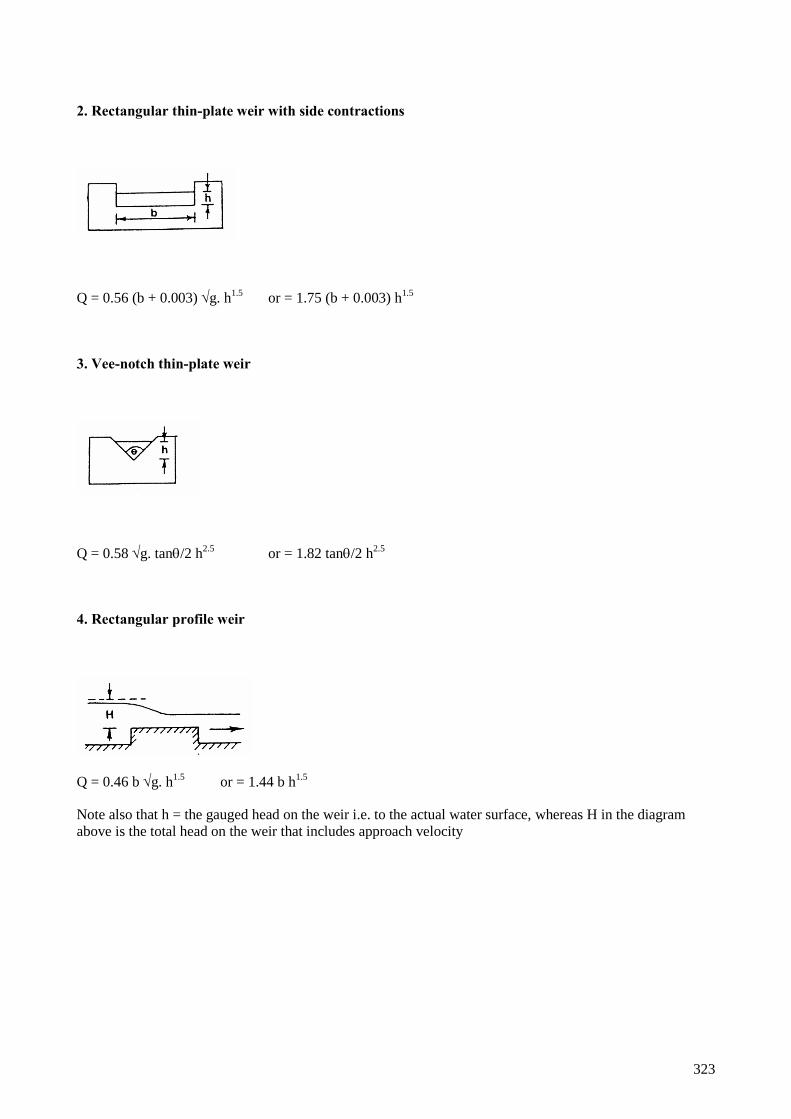
323
2. Rectangular thin-plate weir with side contractions
Q = 0.56 (b + 0.003) g. h1.5
or = 1.75 (b + 0.003) h1.5
3. Vee-notch thin-plate weir
Q = 0.58 g. tan/2 h2.5
or = 1.82 tan/2 h2.5
4. Rectangular profile weir
Q = 0.46 b g. h1.5
or = 1.44 b h1.5
Note also that h = the gauged head on the weir i.e. to the actual water surface, whereas H in the diagram
above is the total head on the weir that includes approach velocity

324
5. Broad horizontal-crested weir with rounded edges
Q = 0.544 b g. h 1.5
or = 1.70 b h1.5
Note that most broad or narrow-crested weirs with no shrap edges and a will have a multiplying factor i.e Cd
√g in the range 1.5-1.7
Note also that h = the gauged head on the weir i.e. to the actual water surface, whereas H in the diagram
above is the total head on the weir that includes approach velocity
6. Triangular profile Crump weir
Q = 0.633 b g. h1.5
or = 1.98 b h1.5
Note also that h = the gauged head on the weir i.e. to the actual water surface, whereas H in the diagram
above is the total head on the weir that includes approach velocity
7. Ogee weir
Q = 0.67 b g. h1.5
or = 2.10 b h1.5
Note also that h = the gauged head on the weir i.e. to the actual water surface, whereas H in the diagram
above is the total head on the weir that includes approach velocity

325
8. Rectangular flume
Q = 0.544 b g. h1.5
or = 1.70 b h1.5
Note also that h = the gauged head on the weir i.e. to the actual water surface, whereas H in the diagram
above is the total head on the weir that includes approach velocity
9. Submerged orifice (which would include a submerged vertical sluice gate)
The general equation for the discharge is Q = Cd A 2gh
where Cd is a coefficient of discharge, and
A is the area (m2) of the orifice (b x d)
For a typical sharp edged sluice or orifice we can take Q = 0.61 A 2gh
Note that any bevelling or rounding of the edges of the orifice will increase its discharge coefficient, which
can then vary the from about 0.65-0.85
10. Vertical gate not obstructed by the tail-water
The free discharge below a sluice gate is a function of the upstream water depth and the gate opening.
Q = Cd bw2gY1
Where Cd = (Cc /1 + w/Y1), and Cc = 0.61

326
11. Accounting for approach velocity
The equations for weirs above ignore the approach velocity of the water to a weir. If the mean velocity of the
water approaching the weir is known then this can be reflected in the calculation of flow. It is only of real
significance if approach velocities are high, say more than 1m/s.
Say discharge over a weir is say Q = 1.7 b h 1.5
Where h = static head a distance at leat 2.5h upstream of the leading edge of the structure
Given that the theoretical velocity of falling water V = 2gh by squaring it and transposing it we can
estimate a value for its equivalent velocity head h1 thus
h1 = V2/2g
by combining this with the equation above discharge becomes
Q = 1.7 b [(h + h1)1.5
- h1 1.5
]
12. Pool pass – pool & notched traverse
The general equation for free-flowing rectangular notch
Q = Cd b (2g)0.5
h1..5
Where Cd is a coefficient of discharge that can vary between 0.33 for a gap forming a broad-crested weir, to
0.5 for a notch with an ogee weir shaped traverse. In most cases it will be about 0.4.
Alternatively for the typical profiled notch used in a conventional P&T fish pass the Francis equation is used
Q = 1.84 (b – 0.2h) h1.5
Where b = notch width (m)

327
13. Pool pass – vertical slot
Q = Cd b H1 (2gDH)0.5
Where Cd is a coefficient of discharge that can vary between 0.65 for a sharply bevelled slot to 0.85 for a
well-rounded slot
14. Pool pass – deep slot
Flow in the pass Qn = K. Qd
where Qd = Cd b h1 (2gDH)0.5
while K = [ 1 – ((H1 – DH)/H1)1.5
]0.385
15. Flow in open channels
Q = A. V.
where A = cross-sectional area
and V = (1/n) Ro.667
S0.5
(Manning formula)
where R = mean hydraulic radius = A/ wetted width
S = gradient or slope of the channel
n = roughness coefficient for the channel
Typical values for the Manning constant are as follows:
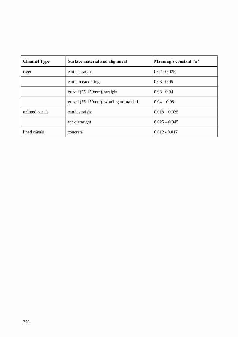
328
Channel Type Surface material and alignment Manning’s constant ‘n’
river earth, straight 0.02 - 0.025
earth, meandering 0.03 - 0.05
gravel (75-150mm), straight 0.03 - 0.04
gravel (75-150mm), winding or braided 0.04 – 0.08
unlined canals earth, straight 0.018 – 0.025
rock, straight 0.025 – 0.045
lined canals concrete 0.012 - 0.017

329
APPENDIX XII Fish Pass Inspection Form
FISH PASS INSPECTION FORM
NB: Before carrying out a fish pass inspection, make sure that you have read and understood the relevant
safe system of work for the site.
NAME OF RECORDER: DATE:
FISH PASS NAME: RIVER:
FISH PASS TYPE: FISH PASS OWNER:
GRID REF: FREQUENCY OF INSPECTION
Specify:
1. IS PASS FUNCTIONING AS EXPECTED? Y/N
(Considering questions below)
2. IS FISH PASS TOTALLY BLOCKED? Y/N
3. IS FISH PASS PARTIALLY BLOCKED? Y/N

330
4. IF Y TO EITHER (2) or (3) ABOVE DESCRIBE PROBLEM:
(Take photos if possible)
5. ANYTHING U/S AFFECTING FLOW INTO PASS? Y/N
IF Y DESCRIBE PROBLEM:
(Take photos if possible)
6. ANYTHING D/S AFFECTING APPROACH INTO PASS? Y/N
IF Y DESCRIBE PROBLEM:
(Take photos if possible)
7. IS PASS DAMAGED IN ANY WAY? Y/N
IF Y DESCRIBE PROBLEM:
(Take photos if possible)

331
8. ANY OTHER COMMENTS :
Eg: If this pass is on a spawning tributary you may want to record number of redds up and downstream
over a measured reach
You may consider that there is too much/ too little water in the pass even though it's not blocked.
You may consider that there is something wrong with the fish pass design, perhaps there are fish
jumping on the weir and not going into the pass or the water drops a long way so difficult for fish to
get into the pass.
If the fish pass is equipped with a gauge board(s), enter the reading(s).
DATE REMEDIAL ACTION COMPLETED: COST :
DESCRIBE REMEDIAL ACTION:

332
APPENDIX XIII List of Abbreviations
ADF Annual Daily Flow
AFER Area Fisheries, Ecology and Recreation (Manager)
BCU British canoe Union
CCW Countryside Council for Wales
CDM Construction, Design and Management Regulations for planning
CROW Countryside and Rights of Way Act 2000
cSAC Candidate Special Area of Conservation
EA Environment Agency
EC European Community
EN English Nature
EWF Emergency Work Force
FA Final Approval
H&S Health and Safety
NCPM National Capital Programme Management
NFPP National Fish Passage Panel
NFPO National Fish Pass Officer
NRA National Rivers Authority
ODN Ordnance Datum Newlyn
OLDSI Operation Likely to Damage features of Special Interest
PA Provisional Approval
PAB Project Approval Board
PI Policy Instruction
PID Project Implementation Document
PPG Planning Policy Guidance
Q Discharge (m3s
-1)
Q90 Percentile Exceedance Value (in this case a value exceeded for 90% of the time, i.e. a low flow)
R&D Research and Development

333
SAC Special Area of Conservation
SAFFA Salmon and Freshwater Fisheries Act 1975
SI Statutory Instrument
SoD Scheme of Delegation
SoS Standard of Service
SPA Special Protection Area
SRT Self Regulating Tideway (gate)
SSSI Site of Special Scientific Interest
SWIMIT Swimming Information Technology
TBM Temporary Bench Mark
UK United Kingdom

334
APPENDIX XIV Monitoring Programme Examples
Examples of detecting change in upstream populations to demonstrate the
effectiveness of a fish pass
Sources of information and data, and their relative value, have been outlined in section entitled ‘Methods for
determining the effectiveness of fish passes’ (page 223). At the very beginning of the process a management
decision needs to be made regarding what level of change in the chosen parameter (e.g. a doubling, trebling
etc) would indicate that the pass is effective. The approach that follows utilises the overall variance
including temporal, spatial, random and movement.
The duration of the study and the number of sites sampled post-construction will depend on the management
decision of the level of change that is to be detected. It will also depend on the overall variability of the data,
the number of sites sampled, and the number of years of data available prior to the construction of the fish
pass.
Statement of required precision
Proof of effectiveness can be derived from a statistical determination of whether there has been a significant
improvement in the population following the construction of a fish pass. For example, the hypothesis (null
hypothesis, Ho; a statement of no difference) would be that the study aims to test whether the size of the
population before the construction of the pass was different to the size of the population post-construction
(Ho: population before = population after). Alternatively the study could aim to test whether the size of the
population before the construction of the pass had increased by a fixed amount (Ho: population before =
population after + difference). If the null hypothesis is false then the alternative hypothesis is deemed to be
true, for example the population after construction is significantly different from the population post-
construction (i.e. Ha: population before = population after construction).
In any such test there are two types of error:
Type I - Ho is rejected when Ho is true. The probability of this occurring is denoted by the significance
level [eg setting = 0.05 means there is a 5% chance of rejecting Ho (the size of the population pre and
post construction are not the same) when if fact they were the same].
Type II - Ho is accepted when the alternative hypothesis (Ha) is in fact true (eg. the size of the population pre
and post construction are the same when in fact they were different). This probability is denoted by the value
. Therefore 1- (= power) is the probability of accepting Ha when Ha is true.
The two types of error are inversely related. A decrease in a Type I error will increase the probability of a
Type II error, for any given sample size. The only way of reducing both sets of error is by increasing sample
size. The ideal statistical test is one that has a small probability of rejecting Ho when it is true and a large
probability of rejecting Ho when it is false.
The effect of different values of alpha () and beta ().
Let it be assumed that the monitoring programme aimed to determine whether the population post
construction (P2) had increased by a certain amount (d) of the pre construction population (P1).

335
Let the actual change in the population be X (= P2 / P1; or = P2 - P1) and therefore the null hypothesis being
tested is whether
Ho: X d against the alternative hypothesis Ha: X d.
The influence of alpha and beta and the minimum difference (d) in the population level pre and post
construction can be examined through their effect on the standard error of the difference pre and post
construction (X).
The standard error (SE) of the observed change in the size of the population (X) is:
SE(X) d / (u/2 + u) equation *1
Where u/2 is the upper 100(1- /2) percentage point and u the upper 100(1 - ) percent point of the
Standard Normal distribution (Appendix Table 1) The difference (d) can be either a specific amount or a
multiple of the pre construction level. In the case of the former the actual value is substituted into equation
*1, while if a multiple of the pre construction is being considered the Logarithm (Log d) is used.
Appendix Table 1 Values of alpha and beta for different levels of probability
Probability
u/2
u
0.01
2.576
2.326
0.05
1.960
1.645
0.10
1.645
1.282
0.20
1.282
0.842
0.30
1.036
0.524

336
By substituting various values into equation *1 it is possible to determine the standard error for different
levels of alpha, beta and the detectable difference in the population level pre and post construction. The
smaller the standard error the more intensive the monitoring programme needs to be to detect the difference
in the population level post construction of the fish pass.
For example, where the monitoring programme is being used to determine whether the population had
increased post construction by a certain multiple of the pre construction level, tables can be created to
examine the implications of changing the various parameters (Appendix Table 2).

337
Appendix Table 2 Standard error to achieve a particular detectable difference (multiple) in the
population level pre and post construction at various levels of alpha and beta
Alpha
0.05
0.05
0.05
0.10
0.10
0.10
Beta
0.10
0.20
0.30
0.10
0.20
0.30
Detectable
difference(multiple)
0.67 / 1.5
0.13
0.14
0.16
0.14
0.16
0.19
0.50 / 2.0
0.21
0.25
0.28
0.24
0.28
0.32
0.40 / 2.5
0.28
0.33
0.37
0.31
0.37
0.42
0.33 / 3.0
0.34
0.39
0.44
0.38
0.44
0.51
0.29 / 3.5
0.39
0.45
0.50
0.43
0.50
0.58
0.25 / 4.0
0.43
0.49
0.56
0.47
0.56
0.64
The multiple column contains two numbers because the standard error would be the same whether the
population halved or doubled its size pre construction.
Assessment of required sampling effort
This will depend on the method being used and whether historic data exists to make comparisons. The issues
can become quite complex and only relatively simple cases with temporal comparisons at one site where
historic data are available are given as examples below. Where things become more complex, for example
temporal comparisons involving more than one site where no historic data is available, then the statisticians
in the National Salmon & Trout Centre should be consulted.

338
Examples of temporal comparisons involving one site where historic data are available.
The method proves a quantitative assessment of effectiveness and involves a comparison of the population,
catch and/or the number of redds, pre and post construction of a fish pass.
The variance of the minimum detectable difference can be calculated as follows (Note: in all calculations the
variance is the variance of the data following transformation by using logarithms (Loge or Log10):
V(X) = (Vt +(Vr+Ve)/n) (1/M2 + 1/M1) equation *2
Where:
V(X) = variance of the minimum detectable difference pre and post construction as a multiple of the pre
construction level
Vt = temporal variance
Vr = random variance
Ve = variance associated with measurement error
Mn = number of years of data pre construction (1) and post construction (2)
n = number of sites
Details on how the various sources of variance can be determined can be found in R&D Note 292 (Wyatt
and Lacey, 1994).
The standard error is estimated using:
SE(X) = V(X) equation *3
And 95% confidence intervals calculated by doubling the standard error:
Confidence limits = 2SE(X) = 2V(X) equation *4

339
A Worked Example using Catch Data
Appendix Table 3 contains catch-data from a hypothetical fishery. In this example it was not possible to
identify the various components of the total variance and the variance calculated represents the combination
of all three, ie (Vt +(Vr+Ve)/n).
Appendix Table 3 Ten years of catch data from a hypothetical fishery (pre construction)
Year
1
2
3
4
5
6
7
8
9
10
Var.
Catch
267
139
304
252
342
511
332
207
747
938
Loge
Catch
5.587
4.934
5.717
5.529
5.835
6.236
5.805
5.333
6.616
6.844
0.3356
The minimum detectable difference in population level pre and post fish pass construction can be
determined by substituting the variance pre construction (0.3356) into equation *3. It is then possible to
estimate the standard error for the minimum detectable difference for various time periods post construction.

340
Appendix Table 4 Standard error for the minimum detectable differences in the population level pre
and post construction for different periods of study post construction
Years Post construction (M2)
Standard Error
1
0.61
2
0.45
3
0.38
5
0.32
7
0.29
10
0.26
These standard errors can then be compared with those calculated in Table IV.ii. It is then evident that with
only two years post construction sampling the increase in population level pre and post construction would
have to be at least 3.5 times the pre construction level to be regarded as significantly different for = 0.05,
= 0.20, or 3.0 times pre construction level for = 0.10, = 0.20.
Alternatively, if post construction sampling was carried out for 10 years, the minimum detectable difference
in the population would be an approximate 2 fold increase (or decrease) in the size of the population pre
construction = 0.05, = 0.20.
A worked example using survey data
In many instances there is no information on variance of the population available. In this case information
needs to be taken from a different river, ideally as close as possible in terms of its physical and biological
characteristics. Appendix Table 5 contains the components of variance for two age classes of trout from two
systems, one in the upper reaches (Lledr) and the other a small stream close to the mouth (Nant-y-Goran).

341
Appendix Table 5 Components of total variance for two rivers (Lledr and the Nant-y-Goran) for two
age-classes of trout. (Spatial variance, though not required in the analysis has been included for
completeness)
Variance
Lledr
O+ trout
Lledr
>O+ trout
Goran
O+ trout
Goran >O+trout
Spatial (Vs)
0.068
1.151
0.170
0.216
Temporal (Vt)
0.173
0.103
0.251
0.224
Random (Vr)
0.529
0.379
0.222
0.350
Measurement (Ve)
0.011
0.008
0.011
0.008
Using the data from the Nant-y-Goran O+ trout, as an example, it is possible estimate the population
difference which could be detected. To do this Vt and Ve are substituted into equation *6 and the number of
sites sampled and the duration of the pre and post construction survey period varied until the required
standard error is achieved.
However, it is evident from Table IV.v that random noise was significant and in some instances was the
major component of the overall variance. Therefore it is important to evaluate the effect of including it in the
monitoring programme. It is therefore suggested that the study should aim to determine whether there has
been a change in the population throughout the reach affected. This would be based on a sub-sample (n) of
the total number of sites available (N).
Using the Nant-y-Goran O+ trout data, including random error (Vr) and assuming 5 sites were sampled out
of a potential of 100 sites, the standard error of the population shows a relatively small increase (Appendix
XIV Table 6).

342
Appendix Table 6 Standard error for the minimum detectable difference in the population for various
periods pre and post construction when 5 sites were sampled (n) out of 100 (N) sites
M2 / M1
1
2
3
5
7
10
1
0.77
0.67
0.63
0.60
0.58
0.57
2
0.54
0.50
0.45
0.44
0.42
3
0.44
0.40
0.38
0.36
5
0.34
0.32
0.30
7
0.29
0.27
10
0.24
However, in reality it is hoped that the installation of a fish pass would make a substantial difference to the
population, possibly by an order of magnitude, thus reducing the duration of the sampling period. Of course,
if the obstruction was impassable prior to the construction of the fish pass then a qualitative assessment
would be adequate as only the presence of the fish would indicate that the fish pass was effective. Though a
more intensive programme would be required if the benefits of constructing the pass were to be quantified.
Analysis of results
The standard error can then be calculated and compared with the aims of the study in a similar way as above
using equation 3. Likewise the 95% confidence limits are obtained using equation 4.

343
Determining the efficiency of a pass - precision and confidence in the measure
Assessment of required precision
The size of the sample required to make an estimate of efficiency is dependent on both the precision with
which the parameter is to be estimated, and the confidence with which the desired precision is to be
achieved. Precision is generally referred to in proportional terms (0.10). Associated with the desired
precision, is the percentage confidence (C) with which the desired precision is to be achieved. For example,
if a fish pass efficiency of 0.70 is to be determined with an error no greater than 0.10 with 95% confidence,
there is a 1 in 20 chance that the true efficiency will be outside the range 0.60 to 0.80.
The use of precision and confidence to develop a monitoring programme is outlined in section 10.5.1.
Assessment of required sampling effort
Estimates of fish pass efficiency to a given level of precision with C% confidence can be calculated using
the following formula:
N = u2p(1-p)/
2 equation *5
where:
N = number of fish to be marked and available to migrate (=ANm)
p = prior estimate of fish pass efficiency
u = Standard Normal deviate corresponding to a cumulative probability of (100-C)/2
= desired level of precision
If prior information exists on the efficiency of a particular type of fish pass (p) this should be substituted into
equation 5. If no information exists then a value 0.5 should be used. Using a prior estimation of efficiency
avoids overestimating the sample size needed to determine efficiency for the required precision and
confidence. For example, if the true proportion is known to be around 0.8 (i.e about 80% of fish successfully
use the fish pass), then ignoring this information will prescribe a sample size nearly 50% greater than that
calculated using the default value of 0.5, i.e. 61compared with 96 @ C = 95%, = 0.10.
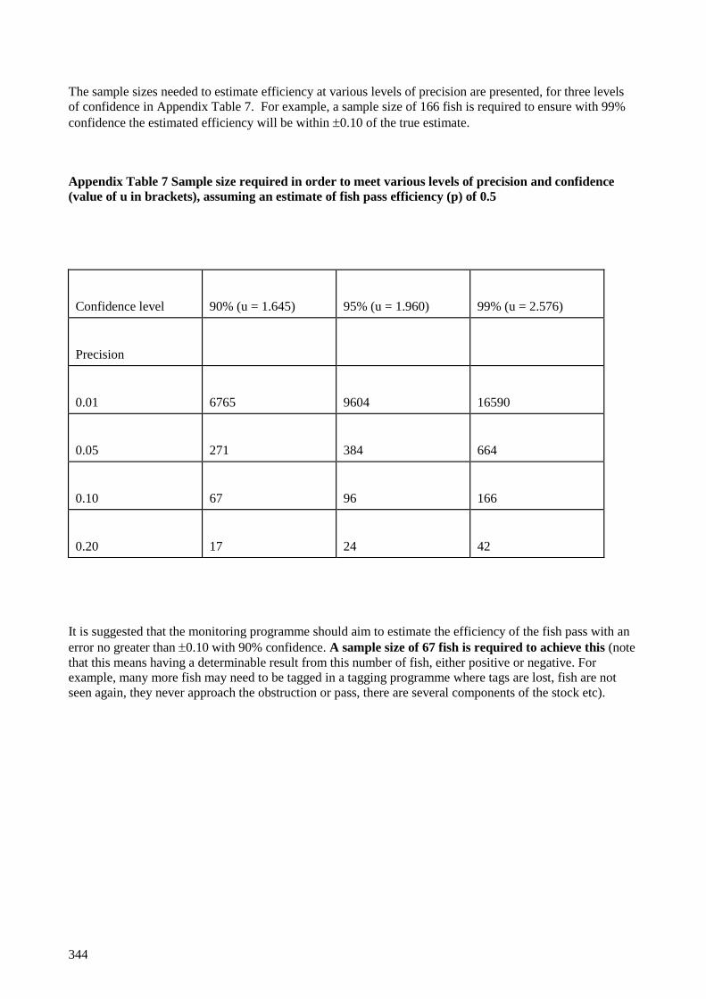
344
The sample sizes needed to estimate efficiency at various levels of precision are presented, for three levels
of confidence in Appendix Table 7. For example, a sample size of 166 fish is required to ensure with 99%
confidence the estimated efficiency will be within 0.10 of the true estimate.
Appendix Table 7 Sample size required in order to meet various levels of precision and confidence
(value of u in brackets), assuming an estimate of fish pass efficiency (p) of 0.5
Confidence level
90% (u = 1.645)
95% (u = 1.960)
99% (u = 2.576)
Precision
0.01
6765
9604
16590
0.05
271
384
664
0.10
67
96
166
0.20
17
24
42
It is suggested that the monitoring programme should aim to estimate the efficiency of the fish pass with an
error no greater than 0.10 with 90% confidence. A sample size of 67 fish is required to achieve this (note
that this means having a determinable result from this number of fish, either positive or negative. For
example, many more fish may need to be tagged in a tagging programme where tags are lost, fish are not
seen again, they never approach the obstruction or pass, there are several components of the stock etc).

345
Analysis of results
Determination of confidence limits.
The upper and lower 95% confidence limits (CL) for the true efficiency can be determined as follows:
Upper 95% CL = (np + 1)Fv1',v2'/(ANm - np + (np + 1)Fv1',v2') equation *6
Lower 95% CL = np / (np + (ANm - np + 1)Fv1,v2) equation *7
where:
v1' = 2(np + 1)
v2' = 2(ANm - np)
v1 = 2(ANm - np + 1)
v2 = 2 np
Fn1,n2 denotes the 5% point of the F distribution with n1 and n2 degrees of freedom. (For example, F12,10 =
2.91).
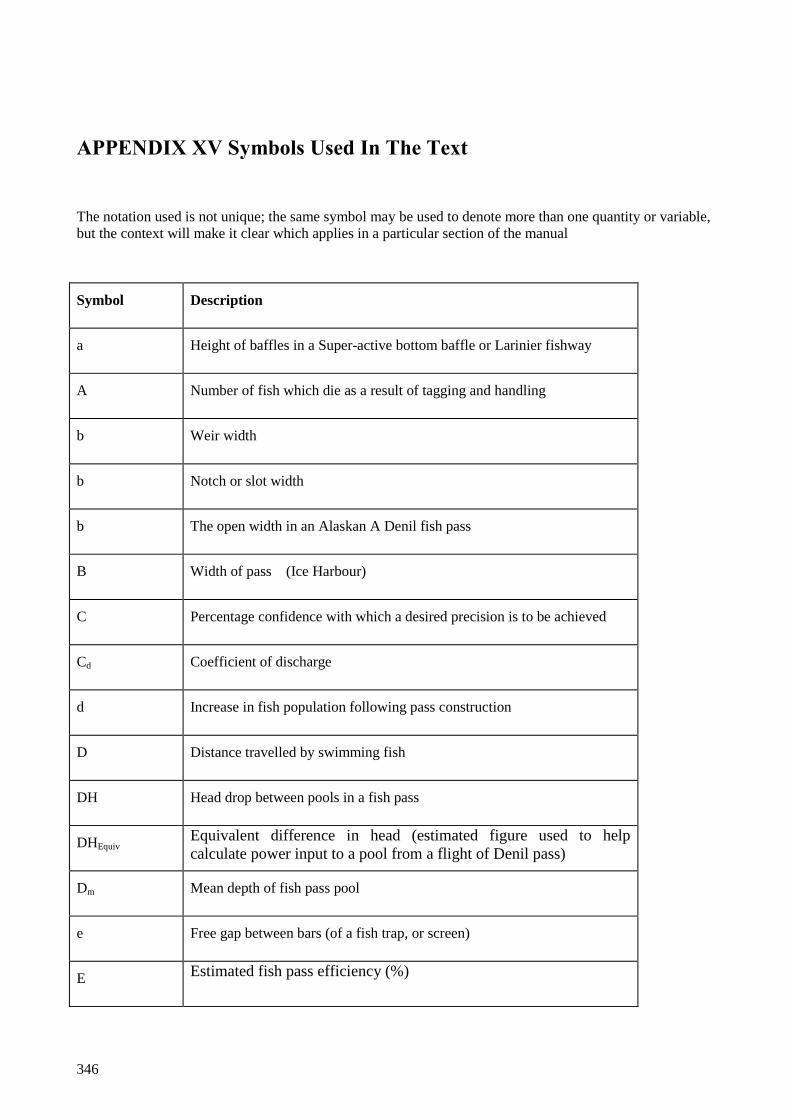
346
APPENDIX XV Symbols Used In The Text
The notation used is not unique; the same symbol may be used to denote more than one quantity or variable,
but the context will make it clear which applies in a particular section of the manual
Symbol Description
a
Height of baffles in a Super-active bottom baffle or Larinier fishway
A
Number of fish which die as a result of tagging and handling
b
Weir width
b Notch or slot width
b
The open width in an Alaskan A Denil fish pass
B
Width of pass (Ice Harbour)
C Percentage confidence with which a desired precision is to be achieved
Cd
Coefficient of discharge
d
Increase in fish population following pass construction
D
Distance travelled by swimming fish
DH
Head drop between pools in a fish pass
DHEquiv
Equivalent difference in head (estimated figure used to help
calculate power input to a pool from a flight of Denil pass)
Dm
Mean depth of fish pass pool
e
Free gap between bars (of a fish trap, or screen)
E
Estimated fish pass efficiency (%)

347
Symbol Description
E
Total energy store
F
A fitness ratio (maximum of depth or width)
g
Acceleration due to gravity (ms-1
)
h
Mean depth in pass from bed (Plane Denil,)
h
Gauged head at gauging weir
h
Mean depth in pass – depth above bottom baffle ( Fatou, Larinier)
h
Water head or depth on a weir or in a notch
ha
Operating head on a baffle fishway (difference in level between the
effective invert of the pass and the water level upstream before it
accelerates towards the pass)
hr Water depth over concrete invert on which baffles are set in baffle
pass (difference in level between the concrete invert and the water
level upstream before it accelerates towards the pass)
Ha
Alternative hypothesis
Ho
Null hypothesis
H1
Depth of water in a vertical slot or deep notch (upstream side)
H2 Depth of water in a vertical slot or deep notch (downstream side)
K
Discharge reduction coefficient (induced by submergence)
L
Length of fish
L
Length of pool in fish pass
L
Standard length of fish (snout to caudal peduncle)
L
Width of channel in a baffle fishway (note single unit width in the case of
a Super-active baffle or Larinier fishway)

348
Symbol Description
M
Free gap in mesh or bar screens
Mn Number of years data pre construction(1) and post construction(2)
n
Number of fish that actually ascend a fish pass
n
Number of sites
np
Number of marked fish that migrate through pass
N
Number of fish to be marked
N
Available stock of fish to go through pass
N
Number of juxtaposed units of Super-active baffle or Larinier pass
N
Number of potential sites
Nm
Number of marked fish
p
Density of water
p
Prior estimate of fish pass efficiency
P
Weir height (gauging weir)
PE
Potential energy entering fish pass pool per second
Pc
Chemical power
Pv
Power dissipation per unit volume or power density
Pr
Power from oxygen uptake
P1
Fish population pre pass construction
P2
Fish population post pass construction

349
Symbol Description
q
Discharge in Denil pass
q
Unitary discharge per metre width of pass Larinier
q*
Dimensionless characteristic of discharge (unitary discharge per metre
width)
Q
Discharge
Qd Discharge through a free flowing notch
Qn
Discharge through a moderately drowned notch or slot (H1-DH/H1
<0.9)
Q*
Dimensionless characteristic of discharge (total discharge)
u
Standard normal deviate
s
Slope as a decimal fraction of 1
S Cross-sectional area of orifice in pool and orifice pass
t
Muscle twitch contraction time
T
Muscle temperature
tm
Endurance time, fish swimming
U
Maximum swimming speed for fish
v
Mean water velocity in a baffle fishway
V*
Dimensionless velocity in Denil pass
V
Estimated average exit velocity
V
Mean water velocity in baffle fishway
V
Volume of receiving pool in fish pass

350
Symbol Description
V
Water velocity
Ve
Variance associated with measurement error
Vr
Random variance
Vt
Temporal variance
V(X) Variance of the minimum detectable difference pre and post construction
as a multiple of the pre construction level
W
Width of pool in fish pass
yo
Depth of water above the invert (bottom baffle) of an Alaskan A fishway
Z Distance as measured downstream from crest of gauging Weir
α
Level of significance
β
Probability
δ
Desired level of precision

APPENDIX XVI Draft Guidance Note: Eel passes at Gauging
Structures
GUIDANCE NOTE
Installation of eel passes at River Flow Gauging Structures
The Eels (England and Wales) Regulations 2009 require that all obstructions that may impede the passage of eels have
eel passes fitted. This is mandatory for both new and legacy structures, including gauging structures. The Regulations
also apply to the maintenance or alteration of the structure and stipulate that the ‘responsible person’ must install and
maintain the pass at their own cost.
Currently an asset matrix tool is being trialled to prioritize the roll-out of eel passes to Environment Agency owned
structures.
The ‘Eels (England and Wales) Regulations 2009’ are available at:
http://www.opsi.gov.uk/si/si2009/pdf/uksi_20093344_en.pdf
National Fisheries and Hydrometry and Telemetry (H&T) functions have agreed the following guidance on the type of
eel pass that is acceptable for installation at river flow measurement structures. They are divided into two categories -
non-invasive and invasive eel passes.
Non-invasive eel pass
Definition: An eel pass that is located above and beyond the area bounded by the wing walls of a gauging structure.
These will be pipe or channel “up and over” type passes with elver-friendly substrate and a pumped flow. Suitable
design solutions are already available. Point of contact for design type is Andy Don. Contact point for head office
fisheries is Greg Armstrong, and for head office H&T is Richard Iredale.
General design principles
1. Both entrance and exit need to be sited in a manner that is acceptable for eel passage1 while not
compromising the performance of the gauging structure2. The lower entrance to the pass should be placed
downstream of the end of the gauging weir wing wall. For hydrometric reasons, the eel pass should be fed
by water pumped from downstream of the structure wherever possible.
2. The pump should abstract no more than 0.5 litres of flow / second3. This assumes that at least half of the
0.5 litre per second is discharged back downstream. Less than half to be discharged upstream of the
structure.

352
3. Such passes can only be installed where minimum flow of the watercourse exceeds 25 litres/second.
4. The siting of the pass entrance and exit should be near the margins of the stream and not mid – channel.
5. At a site where a high flow rating extends beyond the top of the wing walls, the H&T team will need to
consider the impact of the eel pass on that high flow rating.
6. Agreement will need to be achieved between local fisheries and H&T teams on the design of the eel pass.
7. The H&T team can object to the installation of an eel pass if it considers it has justifiable reasons.
Adjudication of disputes will be resolved by the Regional H&T Client Panel.
Notes
1 Near the toe of the obstruction at the d/s; at the u/s where migrants are safe from risk of wash-back
2 Avoids snagging debris or interfering with flow lines
3 Experience has shown that if correctly sited eels will find a very small attraction flow. The nominated flow is sufficient for a bristle pass
200 mm wide that will allow thousands of eels to pass per night. The pump only needs to be operating from dusk till dawn. Key months for use of pass: April-September with some Regional variation
The agreement between Fisheries and H&T will principally cover the design requirements but will also cover -
Health and safety including public access issues at the site.
Electrical issues around any pump installation. Every effort should be made to use ‘green energy’ where
practicable for powering the pump. Where possible pumps should be non mains powered.
The local fisheries department will own the eel pass and be responsible for its maintenance.
Essential elements of the eel pass design include:
Covering the channel to prevent desiccation and predation (desiccation includes, at night time, protection from
prevailing winds)
Capacity to fit monitoring equipment either as part of the installation or retrospectively e.g. CCTV/webcam
Suitable eel substrate choice for the site.
Invasive eel pass
Definition -Eel passes that are located within the area bounded by the wing walls of a gauging structure
Two methods are approved.
1. Pipe or channel “up and over” type passes with elver-friendly substrate and a pumped flow
2. Vertical bristle board eel passes.
1. Pipe or channel “up and over” type passes

353
These will be pipe or channel “up and over” type passes with elver-friendly substrate and a pumped flow but whose
layout and configuration brings it within the area bounded by the gauging structure’s wing walls at some point.
Agreement will need to be achieved between both local and national Fisheries and H&T functions Suitable design
solutions are already available. Point of contact for design type is Andy Don. Contact point for head office fisheries is
Greg Armstrong, and for head office H&T is Richard Iredale.
General design principles
The same general design principles and requirements set out above for Non Invasive eel passes are to be followed with
the addition of the following -
1. Passes within the walls of a flow gauging weir may be acceptable at some sites if the entire installation is mounted
above the level of modular limit for the weir.
2. Where high flows need to be accurately gauged, passes mounted in the weir-channel at high level are not
acceptable
3. In rivers where trash and debris could be a significant problem, eel passes mounted within the gauging channel
wing wall will be especially vulnerable to damage during high flow events and should be avoided where possible.
2. Vertical bristle board eel passes on crump weirs
Vertical board eel passes are designed to be installed on crump type weirs. The eel pass is constructed of boards that are
supplied in 1mt long and 0.4m wide sections with bristle tufts 70mm long spaced at 30mm intervals set on a backing
board 10mm thick. They are mounted vertically along one side of the crump weir adjacent to the wing wall.
General design principles
1. The base of the board will make a smooth joint with the upstream and downstream slopes of the crump weir.
2. The boards shall run parallel to the wingwall and be mounted so that the end of the bristle touches the
wingwall and that the outer face of the backing board is set 80mm out from the wingwall.
3. The board shall extend downstream sufficiently far enough to ensure that the end of the board is always below
the lowest downstream water level expected at the site. This would normally be at or beyond where the
downstream 1 in 5 slope of the crump weir terminates.
4. The board shall extend sufficiently far enough upstream to at least the point where the upstream slope of the
crump meets the river bed. Where possible it is desirable to extend the board upstream as far as possible. In
practical terms this is usually restricted to where the wingwall return curves back into the bank. It is important
not to impede the stilling well inlet pipe.
5. The board shall extend to the top of the wingwall or 1.2m above the weir crest which ever is the lesser.
6. The outer face of the board will be smooth with no external fixings or fastenings protruding into to the flow of
the river.
7. It should be mounted in such a manner that it can be taken off for cleaning if required.
8. The boards can only be installed on crump weirs that are wider than 4mts in width. The installation ofthe
board has the effect of reducing the flow calculated over a 4m wide weir of between 1.2 to 1.5%. This
reduction in flow becomes less on wider weirs.
9. On crump weirs between 2m and 4 m wide, boards with 30mm bristles and spaced at 30mm may be installed.
This gives the same % reduction in flow as item 8 above.
10. Boards cannot be installed on weirs narrower than 2m.