Embed Size (px)
Citation preview

Institute of Engineering
PASHCHIMANCHAL CAMPUS
Solar Charging
Abinash Baral(BEX/071/402)Archana Mallick(BEX/071/408)
Bibek Nabin Subedi(BEX/071/422)
Department of Electronics and Computer Engineering
Supervisor:
Laxmi Prasad Bastola
Tribhuvan University
Institute of Engineering
PASHCHIMANCHAL CAMPUS Lamachaur, Pokhara
A Project Report
on
Solar Charging Coin Based Mobile Charging System
Submitted By: Abinash Baral(BEX/071/402)
Archana Mallick(BEX/071/408) Bibek Regmi(BEX/071/410) Nabin Subedi(BEX/071/422)
Submitted To: Department of Electronics and Computer Engineering
……………………
Laxmi Prasad Bastola Date:
Coin Based Mobile Charging System
Department of Electronics and Computer Engineering
……………………
Date:2074/04/26
ii | P a g e
ACKNOWLEDGEMENT
We wish to express our sincere thanks to the Department of Electronics and Computer Engineering, Pashchimanchal Campus for accepting our proposal and providing us with an opportunity to work on the project titled “Solar charging coin based mobile charging system”. We also would like to appreciate Mr. Hari Prasad Baral and Mr. SharanThapa for their constant support throughout the various stages of our project. The most grateful gratitude goes to our project supervisor Mr. Laxmi Prasad Bastola for making us aware about the scope of the project and guiding us constantly. Lastly, we want to thank all the other helping hands who assisted in completing our project up to this level.
iii | P a g e
ABSTRACT
This is an era of smart phones. With mobile phones becoming the major source of business/personal communication, the need to provide a public charging service is essential. This project addresses the need of public mobile charging. Once we connect the mobile to the charging slot, we have to put the coins in this coin insertion slot to activate mobile charging. This charging system is dependent on the solar energy, where the solar energy is converted into electrical energy using a solar panel. This project is also a prototype of a mobile charging vending machine and the recommended locations include: Hotels, Conference centers, Exhibition halls, serviced office, Health clubs, Training centers, Shopping mall, Cafes, Universities, Colleges, Airports, Bus parks, Downtowns, etc. where the users can recharge a phone by inserting an authorized coin.
Keywords: Mobile phone, battery charger, solar tracking, microcontroller.

iv | P a g e
TABLE OF CONTENT
ACKNOWLEDGEMENT…………………………………………………………………II
ABSTRACT………………………………………………………………………………..III
LIST OF TABLES……………………………………………………………….…………V
LIST OF FIGURES……………………………………………………………………….VI
CHAPTER-1 INTRODUCTION……..………………………………………………….1
1.1.General Background………………………………………..…………………....1 1.2.Statement of Problem…………………………………………………………....1 1.3.Objectives………………………………………………………………………..2 1.4.Scope………………………………………………………………………….…2
CHAPTER-2 LITERATURE REVIEW.………………………..………………………3
2.1. Coin Based Mobile Charging System………………...………………….……3 2.2 . Solar Tracking System………….………………………………….…………4
CHAPTER-3 METHODOLOGY…………………………..………………..…………..5
3.1. Coin Based Mobile Charger………………………………………..….……....5 3.2. Solar Tracking System……………………………………..…….…………….6 3.3. Component Description…………………………………….………………….8 3.4. Flowchart……………………………………………………………………………17
CHAPTER-4 RESULT & DISCUSSIONS……………….……….…………………..18
CHAPTER-5 APPLICATIONS…………..…………………….………………………18
CHAPTER-6 CONCLUSION…………………………………………………………..19
REFERENCES……………………………………………………………………….……20

V | P a g e
List of Tables
1. Table 1: Technical Specifications of Arduino Mega 2520………….………………. 8
2. Table 2: Pin description of LCD(16*2)…….……………………………………… 10

VI | P a g e
List of Figures
1. Figure 1: Orientation of solar panel based on intensity falling on LDR………….….6
2. Figure 2: Block diagram of coin based solar charging………………...…………….7
3. Figure 3: Arduino mega 2560…………………………………..…………………….8
4. Figure 4: Pin diagram of LCD(16*2)…...……………………………………………9
5. Figure 5(a) LDR symbol Figure 5(b) LDR…………………………………………11
6. Figure 6: Relay pin diagram……………………………………………………...…12
7. Figure 7: Stepper motor and motor driver…………………………………………..13
8. Figure 8: Connection of stepper motor to ULN2003a…………………...…………14
9. Figure 9: 2N2222a transistor……….……………………………………………….14
10. Figure 10(a) Buck converter(switch closed) 10(b) Buck converter(switch open)….15
11. Figure 11: Coin sensor………………………………………………………….…..16
12. Figure 12: Solar Cell…………………………………………………………..……16
13. Figure 13: Flowchart of Solar tracking coin based mobile charging system……….17
1 | P a g e
CHAPTER-1 INTRODUCTION
1.1 General Background In the project, we provide a unique service of coin paid mobile charging system using solar panel [10]. Ordinary solar panel usually faces only in one direction. The solar panel may not get sufficient sun rays to work properly. In this project, solar panel controller is used in order to overcome the defect. The panel will rotate according to the readings read by the LDR. So it will utilize the full sun light to work. This work is mainly designed to control the solar panel automatically, which maintains face of the solar panel towards the sun. This is done by controlling the mechanical movement of the solar panel using a stepper motor. In ordinary system, if the solar panel faces towards east then it cannot change the direction towards sun during sunset. Because of this reason, solar panel may not get sufficient sun rays to work with [20].This problem is overcome by using LDR. In this project we further build a microcontroller based solar charger. A Coin Based Universal Mobile Battery Charger is designed to aid in the event of unpredictable grid power where all the abundant solar power is put to some good use. This device is like a vending machine for mobile battery charger and the user has to plug the mobile phone into one of the adapters and insert an authorized coin: the phone will then be given a micro pulse for charging at a constant current for a definite duration. The charging capacity of the mobile is designed with the help of pre defined values. It is, of course, possible to continue charging the mobile by inserting more coins. This compact and lightweight product is designed to cater for unavailability of grid power[15]. A suitable microcontroller is programmed for controlling all the applications.
1.2 Statement of Problem Mobile phones have become an indispensable part of our business/personal communication. Due to the frequent power cut, we might run out of charge at any instance and fail to attend important calls, send/receive texts/mails or complete other tasks in our phone while we are travelling. Nowadays students and many other people use the public transportation, people who are making every long journey in order attend business conventions, conferences, or for any private purpose don’t know their battery level is low and they often forget their charger at home or it in hotel room. Even through one or two power points are provided at a particular place, it is not sufficient, therefore need to provide a public charging service is essential and coin based mobile charging are designed to solve these problem. Light gathering is dependent on the angle of incident of the light source providing the power to the solar cell surface: the closer to perpendicular, the greater the power. Sun rays will have an angle of incidence close to 90 degrees. At such an angle, the light gathering ability of the cell is essentially zero, resulting in no output. As the day progresses to mid day, the angle of incidence approaches zero degree, causing a steady increase in power until at the point where the light incident on the panel is completely
2 | P a g e
perpendicular, and maximum power is achieved. From this background we see the need to maintain the maximum power output from the panel by maintaining the angle of incident as close to zero degree as possible which can be done by tilting the solar panel to continuously face the sun Our project will provide necessary solutions for above mentioned problems using solar tracking coin based mobile charging system.
1.3 Objectives
Specific objective • To design a Solar Tracking Coin Based Mobile Charging System General objectives • To provide instant charging in the public places and to cater for the unavailability of grid power. • To maintain perpendicular light incidence on solar panel.
1.4 Scope This solar tracking coin based mobile charging system is just a prototype which can be designed, developed and manufactured in large scale. As this project uses a solar energy and is very useful to those in need of emergency mobile charging, this project is for the future. Rapid population growth and industrialization, demands for an increased amount of electrical energy. Solar energy is the best and cheapest alternative at the moment. Since this project makes the use of solar charging system, it promotes solar energy. This prototype can be designed and manufactured easily. It has a wide range of applications. These machines can be installed at various public places for the users who are in need of immediate mobile charging. Vending type machines are almost non-existent in Nepal and are limited within malls. This project also promotes an idea of vending machines in Nepal.

3 | P a g e
CHAPTER-2 LITERATURE REVIEW
2.1 Coin Based Mobile Charging System
In this modern world of globalization and communication, mobile telephone business has grown profoundly [1], and this business is currently worth billions of dollars and supports millions of smart phones [20]. The number of Android and I-phone users is increasing and with the advent of technologies, smart phones are capable of performing various tasks which requires more battery supply [19]. Due to the excessive use of these mobile phones, one may run out of the battery any time and miss important texts/calls or emails. As very few people carry standard mobile charger and it is very difficult to get an electricity connection in public places, there is a need of public mobile charging. M.S. Vandarajan and et al in 2012 designed a coin based mobile battery charger providing a unique service to the rural public where grid power is not available for partial/full daytime and a source of revenue for site providers. The coin-based mobile battery charger can be quickly and easily installed outside any business premise. They used a solar panel, a coin sensor, LDRs, a LCD panel and a suitable microcontroller to control all the applications. They used an Indian 2 rupees as a sample coin, used a coin sensor to detect the coin and accept or reject it accordingly. The project was successful as they were able to obtain the maximum output voltage of 6 volts and maximum output current of 4.5 Ah which was able to cater for the unavailability of the grid power in rural areas [15]. Aparna D. Pawar in 2015 designed a project named coin based mobile charger using solar. In the system, mobile charging was started when it was inserted to the charging slot. But, initially the coin had to be inserted and according to the coin inserted, mobile was charged up to some percentage, She used Indian currencies 1Rs,2Rs,5Rs,10Rs. for mobile charging which was capable of charging multiple mobiles at the same time. Attaching the number of mobiles simultaneously didn’t slow down the speed of charging and the charging would continue if we add more coins. This project used a solar panel of dimension 650x560x43 mm 40WP capable of supplying up to 3.0 A. The mobile would charge from the Lead acid battery, and this battery was charged via solar panel. All activities related to this is displayed on LCD. The project was able to design a coin based solar mobile charger which was capable of providing output voltage of 6 volts and output current of 5 Ah[3].
4 | P a g e
2.2 Solar Tracking System Capturing and transforming the sun’s energy into electricity using photovoltaic collection technology has been an ongoing research topic since the early 1960’s. In more recent years, the demand has grown significantly for solar electric power generating systems thus causing the production to rise as well [9]. Ordinary solar panel usually faces only in one direction. The solar panel may not get sufficient sun rays to work properly [20], thus there comes a need of solar tracking system. S.B. Sridevi and et al in 2013 designed a Coin based mobile charger using solar tracking system. In that system the mechanical movement of the solar was controlled through the stepper moto. 3 LDR’s were placed on arch. So according to the sun movement LDR intensity was varied where the sun light intensity was more LDR intensity was less and depending upon LDR intensities stepper motor was rotated to the side where the LDR intensity was found to be less so that solar panel also rotates. Power optimization was done by using LDR. If the surrounding light was less then LDR read maximum. According to the value of LDR the ADC showed the reading. The ADC sent this value to microcontroller. According to the value sent by the ADC the microcontroller glow the LED through relay. If the intensity of the light wad more meant all the LED array were OFF. Depending upon the intensity of the light LED arrays were switched ON or OFF [20]. Ekta Gupta and et al in 2016 deigned a Coin Based Solar Mobile Charger. In the Solar tracker system, comparator IC1502 was used which compared the results coming from LDR1 and LDR2. As the light fell on LDR1, motor driver IC LM339N drove the motor in clockwise direction and the panel in east direction and when the light fell on LDR2, IC drove the motor in anticlockwise direction and the panel in west direction. When the light fell on both the LDRs, motor stopped working. So, basically LDRs sensed the light intensity. Where the sunlight intensity was more, LDR intensity was less [8].
5 | P a g e
CHAPTER-3 METHODLOGY
3.1 Coin Based Mobile Charger
Input Stage The mobile battery charger starts charging a mobile connected to it when an authorized coin is inserted at the coin insertion slot at the input stage. Any other coin, if inserted in the slot, will be returned to the refund box. A sensor attached to the coin insertion slot accepts the coin into the battery charging unit and starts charging the mobile battery for a specified period controlled by the microcontroller. The sensor uses an sample coin and accepts or rejects the coin on the basis of its dimensions.
Controller This section acts according to the input signal from the sensor circuit. Coin accepted or rejected is based on the parameter of the coin like diameter, magnetic or non-magnetic etc. This invokes microcontroller along with LCD interface displays the message like “insert coin” and charge the mobile for a particular duration of time. When the routine completes, it goes back to the initial stage asking the user to insert a coin.
Output Stage The LCD displays all the information to the user as and when required. When the mobile phone is plugged, it displays “Insert Coin”. When the mobile charging triggers, it displays “Charging” and at the end of charging cycle, it goes back to initial stage showing “Insert coin”. For charging continuously the user can insert any number of coins, the value of which can be controlled through the microcontroller. The output has different terminals for connecting different mobiles.

6 | P a g e
3.2 Solar Tracking System The mechanical movement of the solar is controlled through the stepper motor. LDRs: light dependent resistors, whose resistivity is a function of incident electromagnetic radiation. Higher the light intensity lower is its resistance.
The figure below shows that when the sun at the right to the solar panel, LDR2 has small value of resistance and the other LDR has no light (large resistance) and the microcontroller translates this to the signals to control the stepper motor to rotate the panel to the left. The mechanical movement of solar panel is controlled by the stepper motor. LDRs are placed on the architecture of the system. The intensity of LDR is varied according to the movement of sun. If the intensity of sun rays is more, the LDR intensity will be less. When the LDR intensity is less, the stepper motor rotates accordingly to detect the maximum intensity of sun. In this system, LDRs are used because they have lower power consumption. ADC converts the value read by LDR to digital and feeds those values to microcontroller which processes the data accordingly.
Figure 1: Orientation of solar panel based on intensity falling on LDR

7 | P a g e
The basic block diagram of Coin Based Solar Tracking System is drawn below:
Figure 2: Block diagram of coin based solar charging
Mobile charger
Relay
Motor Driver
LCD Display
Motor
Coin Sensor Solar panel
LDR
LDR
Arduino
mega
2560
Battery
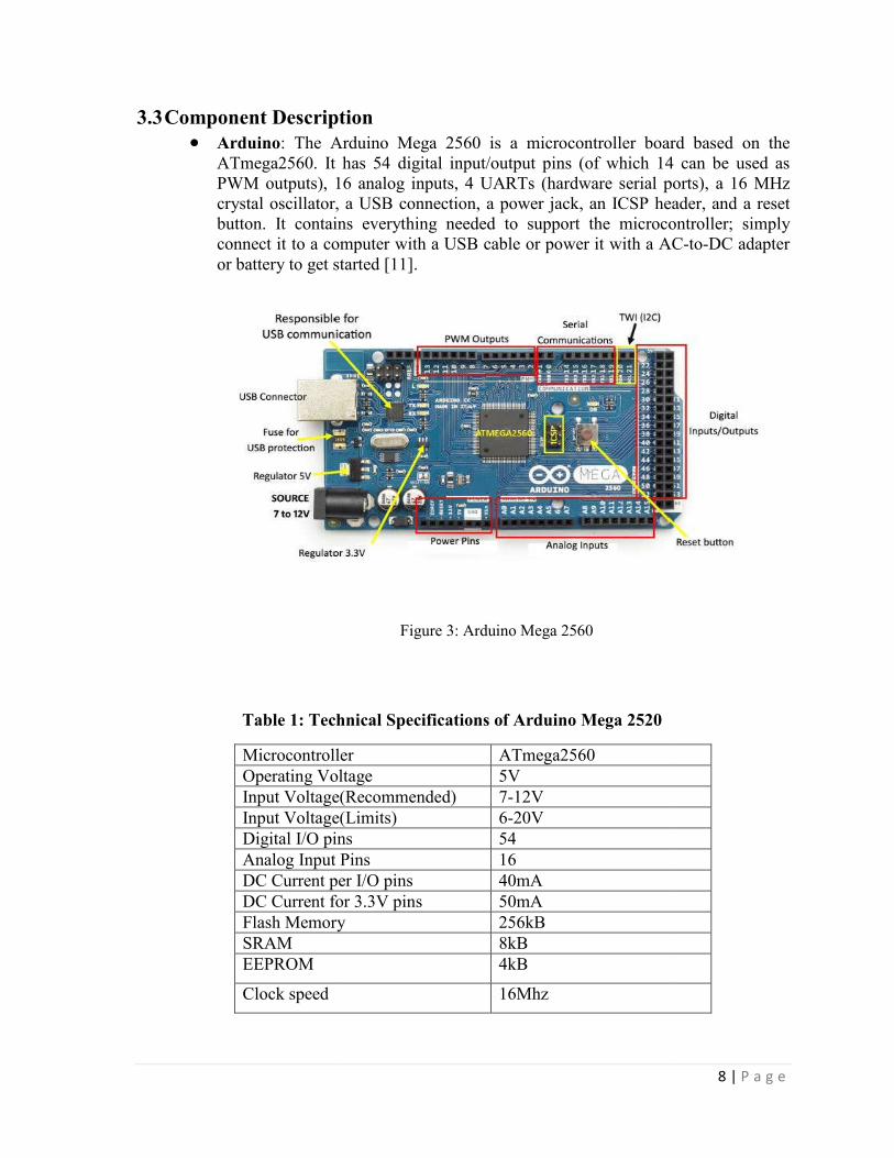
3.3 Component Description Arduino: The Arduino Mega 2560 is a microcontroller board based on the
ATmega2560. It has 54 digital input/output pins (of which 14 can be used as PWM outputs), 16 analog inputs, 4 UARTs (hardware serial ports), a 16 crystal oscillator, a USB connection, a power jack, an ICSP header, and a reset button. It contains everything needed to support the microcontroller; simply connect it to a computer with a USB cable or power it with a ACor battery to get started [11].
Table 1: Technical Specifications of Arduino Mega 2520
MicrocontrollerOperating VoltageInput Voltage(Recommended)Input Voltage(Limits)Digital I/O pinsAnalog Input PinsDC Current per I/O pinsDC Current for 3.3V pinsFlash MemorySRAM EEPROM
Clock speed
Component Description The Arduino Mega 2560 is a microcontroller board based on the
ATmega2560. It has 54 digital input/output pins (of which 14 can be used as PWM outputs), 16 analog inputs, 4 UARTs (hardware serial ports), a 16 crystal oscillator, a USB connection, a power jack, an ICSP header, and a reset button. It contains everything needed to support the microcontroller; simply connect it to a computer with a USB cable or power it with a AC
started [11].
Figure 3: Arduino Mega 2560
Table 1: Technical Specifications of Arduino Mega 2520
Microcontroller ATmega2560 Operating Voltage 5V Input Voltage(Recommended) 7-12V Input Voltage(Limits) 6-20V Digital I/O pins 54 Analog Input Pins 16 DC Current per I/O pins 40mA DC Current for 3.3V pins 50mA Flash Memory 256kB
8kB 4kB
16Mhz
8 | P a g e
The Arduino Mega 2560 is a microcontroller board based on the ATmega2560. It has 54 digital input/output pins (of which 14 can be used as PWM outputs), 16 analog inputs, 4 UARTs (hardware serial ports), a 16 MHz crystal oscillator, a USB connection, a power jack, an ICSP header, and a reset button. It contains everything needed to support the microcontroller; simply connect it to a computer with a USB cable or power it with a AC-to-DC adapter

9 | P a g e
Liquid Crystal Display(LCD): A liquid-crystal display (LCD) is a flat-panel display or other electronically modulated optical device that uses the light-modulating properties of liquid crystals. Liquid crystals do not emit light directly, instead using a backlight or reflector to produce images in colour or monochrome LCDs are available to display arbitrary images (as in a general-purpose computer display) or fixed images with low information content, which can be displayed or hidden, such as preset words, digits, and 7-segment displays, as in a digital clock. They use the same basic technology, except that arbitrary images are made up of a large number of small pixels, while other displays have larger elements [16].
Figure 4: Pin diagram of LCD(16*2)
10 | P a g e
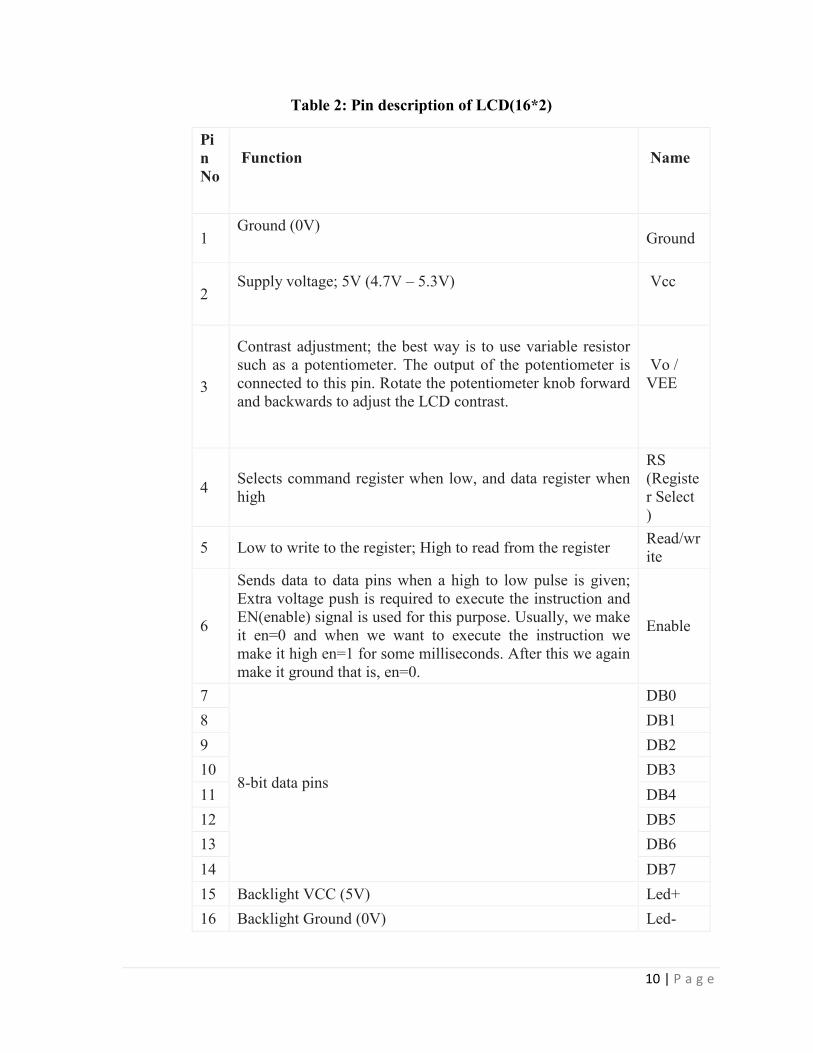
Table 2: Pin description of LCD(16*2)
Pin No
Function Name
1 Ground (0V)
Ground
2 Supply voltage; 5V (4.7V – 5.3V) Vcc
3
Contrast adjustment; the best way is to use variable resistor such as a potentiometer. The output of the potentiometer is connected to this pin. Rotate the potentiometer knob forward and backwards to adjust the LCD contrast.
Vo / VEE
4 Selects command register when low, and data register when high
RS (Register Select )
5 Low to write to the register; High to read from the register Read/write
6
Sends data to data pins when a high to low pulse is given; Extra voltage push is required to execute the instruction and EN(enable) signal is used for this purpose. Usually, we make it en=0 and when we want to execute the instruction we make it high en=1 for some milliseconds. After this we again make it ground that is, en=0.
Enable
7
8-bit data pins
DB0
8 DB1
9 DB2
10 DB3
11 DB4
12 DB5
13 DB6
14 DB7
15 Backlight VCC (5V) Led+
16 Backlight Ground (0V) Led-

11 | P a g e
Light Dependent Resistor(LDR): A Light Dependent Resistor (LDR) or a photo resistor is a device whose resistivity is a function of the incident electromagnetic radiation. Hence, they are light sensitive devices. They are also called as photo conductors, photo conductive cells or simply photocells. A light dependent resistor works on the principle of photo conductivity [12]. Photo conductivity is an optical phenomenon in which the materials conductivity is increased when light is absorbed by the material. When light falls i.e. when the photons fall on the device, the electrons in the valence band of the semiconductor material are excited to the conduction band. These photons in the incident light should have energy greater than the band gap of the semiconductor material to make the electrons jump from the valence band to the conduction band. Hence when light having enough energy strikes on the device, more and more electrons are excited to the conduction band which results in large number of charge carriers. The result of this process is more and more current starts flowing throgh the device when the circuit is closed and hence it is said that the resistance of the device has been decreased. This is the most common working principle of LDR[12].
Figure 5(a): LDR Symbol Figure5(b):LDR

12 | P a g e
Relay: Relay is an electromagnetic device which is used to isolate two circuits electrically and connect them magnetically. They are very useful devices and allow one circuit to switch another one while they are completely separate. They are often used to interface an electronic circuit (working at a low voltage) to an electrical circuit which works at very high voltage. For example, a relay can make a 5V DC battery circuit to switch a 230V AC mains circuit. Thus a small sensor circuit can drive, say, a fan or an electric bulb [18]. A relay switch can be divided into two parts: input and output. The input section has a coil which generates magnetic field when a small voltage from an electronic circuit is applied to it. This voltage is called the operating voltage. Commonly used relays are available in different configureuration of operating voltages like5V, 9V, 12V, 24V etc. The output section consists of contactors which connect or disconnect mechanically. In a basic relay there are three contactors: normally open (NO), normally closed (NC) and common (COM). At no input state, the COM is connected to NC. When the operating voltage is applied the relay coil gets energized and the COM changes contact to NO. Different relay configureurations are available like SPST, SPDT, DPDT etc, which have different number of changeover contacts. By using proper combination of contactors, the electrical circuit can be switched on and off [18].
Figure 6: Relay: Pin diagram

13 | P a g e
Stepper Motor: The stepper motor is an electromagnetic device that converts digital pulses into mechanical shaft rotation [24]. A stepper motor is a brushless DC electric motor that divides a full rotation into a number of equal steps. The motor's position can then be commanded to move and hold at one of these steps without any feedback sensor (an open-loop controller), as long as the motor is carefully sized to the application in respect to torque and speed [23].
Figure7: Stepper motor and motor driver
Motor Driver: A motor driver is a little current amplifier; the function of motor drivers is to take a low-current control signal and then turn it into a higher-current signal that can drive a motor. The simplest way of interfacing a unipolar stepper to Arduino is to use a breakout for ULN2003A transistor array chip. The ULN2003A contains seven darlington transistor drivers and is somewhat like having seven TIP120 transistors all in one package. The ULN2003A can pass up to 500 mA per channel and has an internal voltage drop of about 1V when on. It also contains internal clamp diodes to dissipate voltage spikes when driving inductive loads. Here is schematic showing how to interface a unipolar stepper motor to four controller pins using a ULN2003A.
14 | P a g e
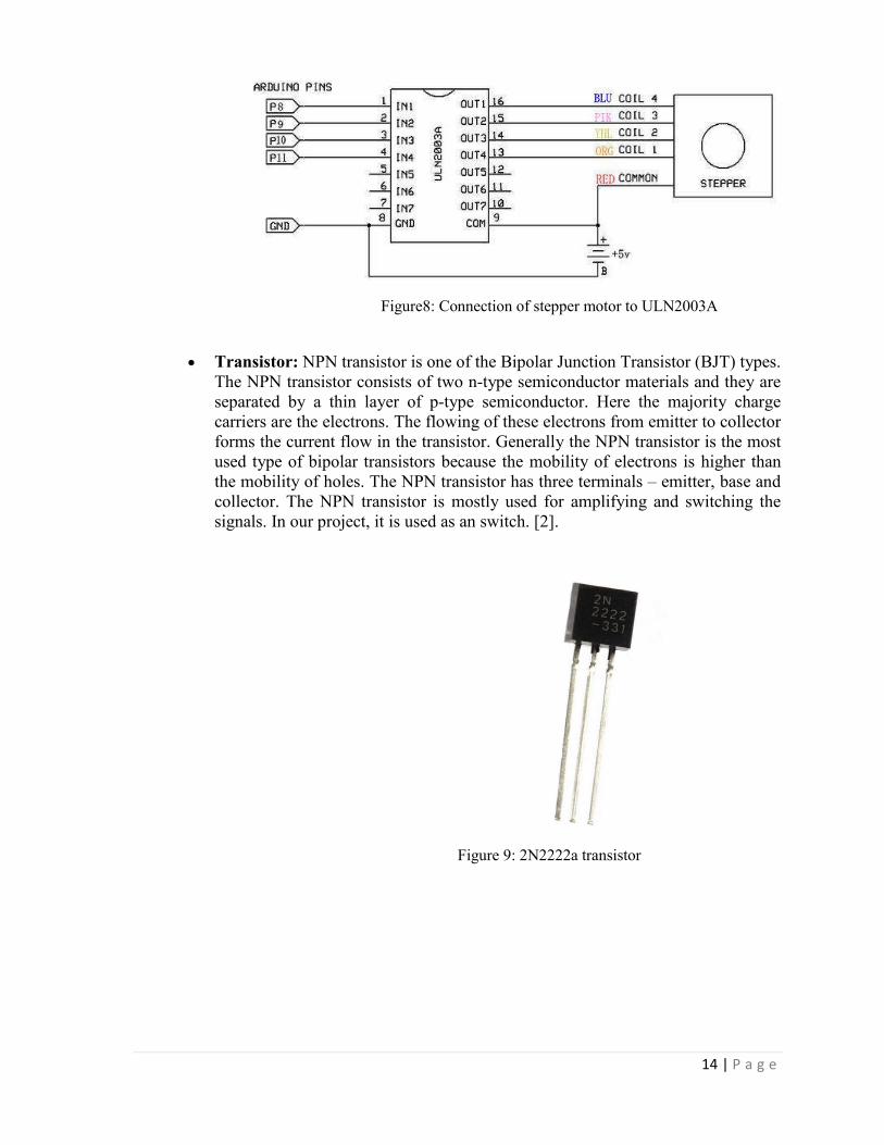
Figure8: Connection of stepper motor to ULN2003A
Transistor: NPN transistor is one of the Bipolar Junction Transistor (BJT) types. The NPN transistor consists of two n-type semiconductor materials and they are separated by a thin layer of p-type semiconductor. Here the majority charge carriers are the electrons. The flowing of these electrons from emitter to collector forms the current flow in the transistor. Generally the NPN transistor is the most used type of bipolar transistors because the mobility of electrons is higher than the mobility of holes. The NPN transistor has three terminals – emitter, base and collector. The NPN transistor is mostly used for amplifying and switching the signals. In our project, it is used as an switch. [2].
Figure 9: 2N2222a transistor

15 | P a g e
Buck Converter: A buck converter (step-down converter) is a DC-to-DC power converter which steps down voltage (while stepping up current) from its input (supply) to its output (load).[6] The fundamental circuit for a step down converter or buck converter consists of an inductor, diode, capacitor and a switch. Typically the switch is controlled by a pulse width modulator.
Buck Converter operation: When the switch in the buck regulator is on, the voltage that appears across the inductor is Vin - Vout. Using the inductor equations, the current in the inductor will rise at a rate of (Vin-Vout)/L. At this time the diode D is reverse biased and does not conduct.
Figure 10(a): Buck converter(switch closed)
When the switch opens, current must still flow as the inductor works to keep the
same current flowing. As a result current still flows through the inductor and into
the load. The diode, D then forms the return path with a current Idiode equal to
Iout flowing through it.
With the switch open, the polarity of the voltage across the inductor has reversed
and therefore the current through the inductor decreases with a slope equal to -
Vout/L. [7]
Figure 10(b): Buck converter(switch open)
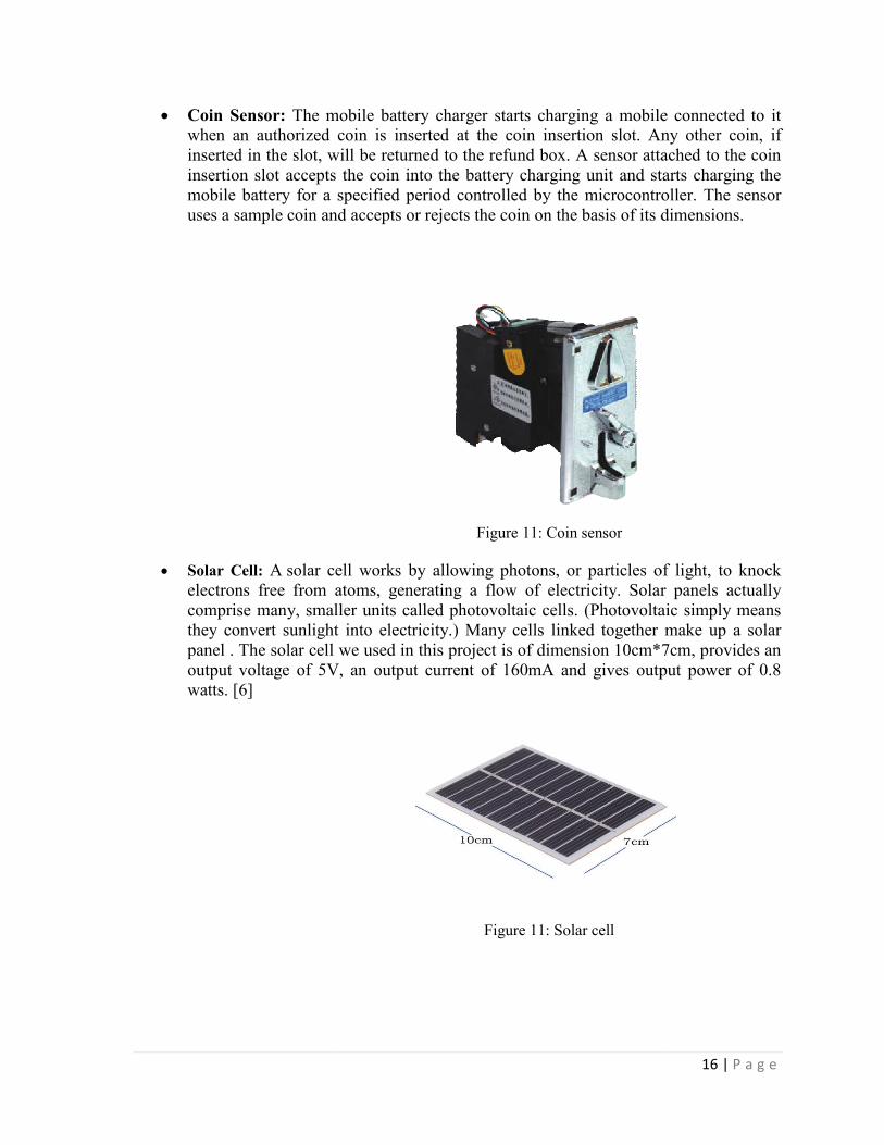
Coin Sensor: The mobile battery charger starts charging a mobile connected to it when an authorized coin is inserted at the coin insertion slot. Any other coin, if inserted in the slot, will be returned to the refund box. A sensor attached to the coin insertion slot accepts the coin into the battery charging unit and starts charging the mobile battery for a specified period controlled by the microcontroller. The sensor uses a sample coin and accepts or rejects the coin on the basis of its dimensions.
Solar Cell: A solar cell works by allowing photons, or particles of light, to knock electrons free from atoms, generating a flow of electricity. Solar panels actually comprise many, smaller units called photovoltaic cells. they convert sunlight into electricity.) Many cells linked together make up a solar panel . The solar cell we used in this project is of dimension 10cm*7cm, provides an output voltage of 5V, an output current of 160mA and gives owatts. [6]
The mobile battery charger starts charging a mobile connected to it when an authorized coin is inserted at the coin insertion slot. Any other coin, if inserted in the slot, will be returned to the refund box. A sensor attached to the coin
rtion slot accepts the coin into the battery charging unit and starts charging the mobile battery for a specified period controlled by the microcontroller. The sensor uses a sample coin and accepts or rejects the coin on the basis of its dimensions.
Figure 11: Coin sensor
solar cell works by allowing photons, or particles of light, to knock
electrons free from atoms, generating a flow of electricity. Solar panels actually comprise many, smaller units called photovoltaic cells. (Photovoltaic simply means they convert sunlight into electricity.) Many cells linked together make up a solar panel . The solar cell we used in this project is of dimension 10cm*7cm, provides an output voltage of 5V, an output current of 160mA and gives output power of 0.8
Figure 11: Solar cell
16 | P a g e
The mobile battery charger starts charging a mobile connected to it when an authorized coin is inserted at the coin insertion slot. Any other coin, if inserted in the slot, will be returned to the refund box. A sensor attached to the coin
rtion slot accepts the coin into the battery charging unit and starts charging the mobile battery for a specified period controlled by the microcontroller. The sensor uses a sample coin and accepts or rejects the coin on the basis of its dimensions.
solar cell works by allowing photons, or particles of light, to knock electrons free from atoms, generating a flow of electricity. Solar panels actually
(Photovoltaic simply means they convert sunlight into electricity.) Many cells linked together make up a solar panel . The solar cell we used in this project is of dimension 10cm*7cm, provides an
utput power of 0.8

3.2 Flowchart
Figure 12: Flowchart of Solar tracking coin based mobile charging system
From the above flowchart, we can observe that when the coin is accepted, the lever opened and the collected gets collected in the collection box. This triggers the mobile charging system, which starts the charging timer and the timer goes in decreasing. When the predefined time of charging is complete, the mobile charging stopcoin, the mobile charging continues and this process keeps going until the user desires and keeps in putting more authorized coins into the coin insertion slot. If a coin is rejected, it gets collected in a refund box.
12: Flowchart of Solar tracking coin based mobile charging system
From the above flowchart, we can observe that when the coin is accepted, the lever opened and the collected gets collected in the collection box. This triggers the mobile charging system, which starts the charging timer and the timer goes in decreasing. When the predefined time of charging is complete, the mobile charging stops. On insertion of next coin, the mobile charging continues and this process keeps going until the user desires and keeps in putting more authorized coins into the coin insertion slot. If a coin is rejected, it gets collected in a refund box.
17 | P a g e
12: Flowchart of Solar tracking coin based mobile charging system
From the above flowchart, we can observe that when the coin is accepted, the lever switch is opened and the collected gets collected in the collection box. This triggers the mobile charging system, which starts the charging timer and the timer goes in decreasing. When the
s. On insertion of next coin, the mobile charging continues and this process keeps going until the user desires and keeps in putting more authorized coins into the coin insertion slot. If a coin is rejected, it

18 | P a g e
CHAPTER-4 RESULT & DISCUSSIONS
The solar panel adjusts its alignment by tilting the panel to continuously face in the direction of sun with the highest intensity. The user, on inserting an authorized coin, can charge a phone for a specified amount of time at 5V and 500mA. Any unauthorized coin is rejected. The LCD displays all the charging status messages to the user. The solar panel tilts according to the difference in intensity of light falling on LDRs. When a coin is inserted to a coin sensor, the pulse is sensed by a microcontroller which then switches the relay and the mobile charging starts. Any error which may occur is due to loose connections or latency in wire.
CHAPTER-5 APPLICATIONS
It is very useful to public for using coins to recharge their phones anytime at any place
Conversion of unused solar energy into useful energy Power management system This prototype can be copied and further expanded for various industrial and
commercial applications Recommended places for installation of such vending machine include: airports,
busparks, downtown, hotels, conference centres, exhibition halls, training centres, shopping malls, universities, etc
It can be used as a solar power bank It can be used in rural areas where there is no grid power Industrial applications.

19 | P a g e
CHAPTER-6 CONCLUSION
A final design of the project was developed within the timeframe of the project submission. The model meets the desired capabilities of producing output power required to charge a few mobiles at a time. This system is adaptable to meet the needs of users in public places. When built on a large scale with a large panel and powerful motors for tracking, it can effectively be used in light prone areas

20 | P a g e
REFRENCES
[1] 1st International Conference on Next GenerationComputing Technologies (NGCT-2015), Dehradun, India, 2015.
[2] A. and A., “NPN Transistor,” Electronics Hub, 30-Oct-2014. [Online]. Available: http://www.electronicshub.org/. [Accessed: 02-Aug-2017].
[3] A D Pawar, "Coin Based Solar Mobile", IJETR, vol. 3, no. 5, 2015.
[4] A H Tirmane,V BKhandara and P S Mali, "Solar Energy Based Mobile Charger", IJREITSS, vol. 5, no. 6, 2015.
[5] A V Borkar, P R Mude, R Satpure and P G Nagpure, "Implementation of Solar Panel Based Mobile Multicharger with Coin Based System", IJRSE, 2017.
[6] "Buck converter", En.wikipedia.org, 2017. [Online]. Available: https://en.wikipedia.org/wiki/Buck_converter. [Accessed: 04- Aug- 2017].
[7] “Buck Converter,” Radio Electronics. [Online]. Available: http://www.radio-electronics.com/. [Accessed: 02-Aug-2017].
[8] E. Gupta, K. A and S. Osheen, "Coin Based Solar Mobile Charger", IJRITCC, vol. 4, no. 4, 2016.
[9] H Bukhamsin, A Edge, R Guici and D Verne, "Solar Tracking Structure Design", 2015.
[10] K N Patil, S Patil, H Kamble, K Sawant and K Kumar, "Mobile Battery Charger on Coin Insertion", IJMTER, vol. 2, no. 4, 2017.
[11] "LifeGate", LifeGate, 2017. [Online]. Available: http://www.lifegate.it. [Accessed: 03- Aug- 2017].
[12] “LDR,” electrical4u. [Online]. Available: https://www.electrical4u.com/. [Accessed: 03-Aug-2017].
[13] L. Science, "How Do Solar Panels Work? | Photovoltaic Cells", Live Science, 2017. [Online]. Available: https://www.livescience.com/41995-how-do-solar-panels-work.html. [Accessed: 03- Aug- 2017].
[14] “Mobile Battery Charger on Coin Insertion”, IRJET, Volume 4, Issue 1, January 2017.
[15] M. Varadarajan, "Coin Based Universal Mobile Battery Charger", IOSR Journal of Engineering, vol. 02, no. 06, 2012.
[16] N. Kawatsuki, H. Takatsuka and T. Yamamoto, "Thermally Stable Photoalignment Layer of a Novel Photo-CrosslinkablePolymethacrylate for Liquid Crystal Display", Japanese Journal of Applied Physics, vol. 40, no. 2, 3, 2001.

21 | P a g e
[17] Pulvirenti, F Milazzo and P Ursino R, in Charger power switch for mobile phones, Analog and Mixed IC Design, 1997.
[18] "Relay", 2017. [Online]. Available: http://engineersgarage.com. [Accessed: 03- Aug- 2017].
[19] R R Khwase, S S Shikure and C Suryabansi, "Coin Based Mobile Charger using Solar Panel, RFID", IJARCET, vol. 4, no. 3, 2015.
[20] S B Shridev, A SaiSuneel and K Nalini, "Coin based mobile charger using Solar tracking system", IJARECE, vol. 2, no. 9, 2013.
[21] S M Karemore, A Welekar and S PWajuekar, "Multicharger System for Mobiles using Solar Panel Based Charging with Coining and Auto Cutoff", ICMTEST, vol. 2, no. 6, 2016.
[22] “Solar Tracking System,” Embedded. [Online]. Available: http://www.embedded.com/. [Accessed: 02-Aug-2017].
[23] "Stepper motor", En.wikipedia.org, 2017. [Online]. Available: https://en.wikipedia.org/wiki/Stepper_motor. [Accessed: 20- Jul- 2017].
[24] “Stepper Motor,” Step Control. [Online]. Available: http://stepcontrol.com/. [Accessed: 03-Aug-2017].