Embed Size (px)
Citation preview

Instant fabrication and selection of foldedstructures using drop impactArnaud Antkowiak1, Basile Audoly, Christophe Josserand, Sébastien Neukirch, and Marco Rivetti
Centre National de la Recherche Scientifique and Université Pierre et Marie Curie, Unité Mixte de Recherche 7190, Institut Jean Le Rond d’Alembert,4 Place Jussieu, F-75005 Paris, France
Edited by William R. Schowalter, Princeton University, Princeton, NJ, and approved May 12, 2011 (received for review February 1, 2011)
A drop impacting a target cutout in a thin polymer film is wrappedby the film in a dynamic sequence involving both capillary forcesand inertia. Different 3D structures can be produced from a giventarget by slightly varying the impact parameters. A simplified mod-el for a nonlinear dynamic Elastica coupled with a drop successfullyexplains this shape selection and yields detailed quantitativeagreement with experiments. This first venture into the largelyunexplored dynamics of elastocapillary assemblies opens up theperspective of mass production of 3D packages with individualshape selection.
elastocapillarity ∣ microfabrication ∣ dynamic self-assembly ∣ thin films ∣surface tension
Capillary forces exerted by a water drop are sufficient tostrongly deform thin elastic objects such as carbon nanotubes
or biological filaments (1, 2) or even to wrinkle thin polymersheets (3). Elastocapillary interactions are abundant in natureand are responsible for phenomena such as lung airway collapse(4) and the clustering of insect bristles (5, 6). They are relevant toa number of applications at the micrometer or nanometer scale,such as microelectromechanical systems (7–9), mass productionof nonspherical lenses (10), or drug delivery (11). On the otherhand, drop impact is one of the most common illustrations offluid mechanics in everyday life, having practical applicationsas diverse as pesticide delivery (12) or polymer inkjet printingfor flexible electronics (13). Impact and splash of droplets havebeen studied for more than a century but only a few studies haveaddressed the case of a compliant substrate, and those are limitedto small deformations (14). Here, the impact of a drop on a veryflexible target is used to produce millimeter-size three-dimen-sional structures instantly. We show that impact allows a gainof five orders of magnitude in the fabrication time as comparedto a previous method based on evaporation (15); in addition, weunveil the possibility to select the shape of the structure, by tuningthe impact parameters. When scaled down and combined withinkjet technology that operates at similar dimensionless numbers,this setup opens up the possibility of mass production of indivi-dualized 3D packings at the submillimetric scale.
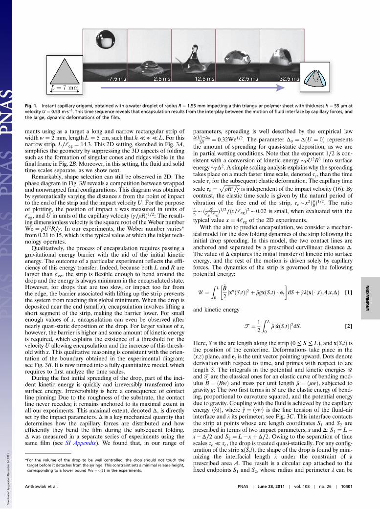
In our experiments, the flexible targets are cut out from thinpolydimethylsyloxane (PDMS) sheets. Such polymer films, natu-rally exhibiting a nonwetting behavior with a water contact angleclose to 110°, are treated to enhance contact line pinning(see Materials and Methods for fabrication details). The targetis laid down on a superhydrophobic surface, which by repellingwater confines the drop onto the target. A water drop of con-trolled volume is released from a given height, thereby allowingcontrol of the impact velocity. For well-chosen impact para-meters, we observe the formation of an instant capillary origami.This concept is demonstrated in the experiment of Fig. 1, where adrop impacts at its center a triangular target of width 7 mm withvelocity U ¼ 0.53 m·s−1. Just after impact, the drop spreads outover the target up to a maximal extent where inertia is balancedby the restoring action of capillarity. Next, surface tension drivesa flow toward the center of the drop, causing the rebound of thedrop (16) and of the elastic film that sticks to it. While in free fall
above the ground, the elastic sheet quickly wraps the drop. Anelastocapillary bundle with a tetrahedral shape is formed and fallsdown to the ground. The whole sequence takes place in 40 ms,which is the typical duration of a hydrophobic rebound (16).When mediated by drop impact, encapsulation is thus consider-ably faster than when driven by evaporation (15), which typicallyrequires half an hour.
Formation of the instant origami is governed by several lengthscales. Let B ¼ Eh3∕½12ð1 − ν2Þ� be the bending modulus of thefilm, E its Young’s modulus, ν its Poisson’s ratio, h ¼ 55 μm itsthickness, L its length, μ ¼ 51.8 × 10⁻³ kg·m−2 its mass per unitarea, g the acceleration of gravity, and γ ¼ 72 mN·m−1 and ρ ¼1;000 kg·m−3 the fluid’s surface tension and density. In all ourexperiments, the initial drop radius is R ¼ 1.55 mm. Wrappinginto a tightly packed structure is made possible by the fact thatthis radius R is both smaller than the gravitocapillary length ℓgc ¼ðγ∕ρgÞ1∕2 ≃ 2.7 mm for the drop to remain spherical and largerthan the elastocapillary length ℓec ¼ ðB∕γÞ1∕2 ≃ 0.55 mm abovewhich capillary forces can make slender objects buckle (1, 6,15). In addition, gravity is important because the size L of thetarget is millimetric and comparable to the elastogravitationallength ℓeg ¼ ½B∕ðμgÞ�1∕3 ≃ 3.5 mm above which gravity bends acantilever beam. These length scales are all relevant and compar-able: Encapsulation results from the mixed effects of gravity,elasticity, and capillarity.
Drop impact, more than just speeding up elastocapillary wrap-ping, also allows for final shape control. A typical illustration ofthis shape selection mechanism is presented in Fig. 2 and inMovies S1 and S2.
In this experiment, a drop impacts a small flower-shaped filmat its center. For a fixed drop radius, different folding scenarioscan be observed depending on the impact velocity. At low impactspeed, spreading of the drop is limited, and the final pattern is thecylindrical folding of Fig. 2A. At higher speeds, the drop quicklyembraces the entire surface of the sheet, and upon retraction apyramidal wrap is obtained; see Fig. 2B. Different instant origa-mis can thus be obtained by simply tuning the velocity of impact.A similar selection can be observed with other target shapes. Inthe case of rectangular films, we observed a competition betweentwo folding modes, one along the length of the rectangle andanother one along its width. The pattern can be selected by vary-ing not only the velocity but also the position of impact. The roleof these two parameters is investigated in detail next.
The phenomenon of dynamic elastocapillary encapsulationcan be carried over to a 2D geometry where it is considerablysimpler to analyze. We carried out a series of systematic experi-
Author contributions: A.A., B.A., C.J., and S.N. designed research; A.A., B.A., S.N., andM.R. performed research; A.A., B.A., S.N., and M.R. analyzed data; and A.A., B.A., andS.N. wrote the paper.
The authors declare no conflict of interest.
This article is a PNAS Direct Submission.1To whom correspondence should be addressed. E-mail: [email protected].
This article contains supporting information online at www.pnas.org/lookup/suppl/doi:10.1073/pnas.1101738108/-/DCSupplemental.
10400–10404 ∣ PNAS ∣ June 28, 2011 ∣ vol. 108 ∣ no. 26 www.pnas.org/cgi/doi/10.1073/pnas.1101738108
Dow
nloa
ded
by g
uest
on
Dec
embe
r 14
, 202
1
ments using as a target a long and narrow rectangular strip ofwidth w ¼ 2 mm, length L ¼ 5 cm, such that h ≪ w ≪ L. For thisnarrow strip, L∕ℓeg ¼ 14.3. This 2D setting, sketched in Fig. 3A,simplifies the geometry by suppressing the 3D aspects of foldingsuch as the formation of singular cones and ridges visible in thefinal frame in Fig. 2B. Moreover, in this setting, the fluid and solidtime scales separate, as we show next.
Remarkably, shape selection can still be observed in 2D: Thephase diagram in Fig. 3B reveals a competition between wrappedand nonwrapped final configurations. This diagram was obtainedby systematically varying the distance x from the point of impactto the end of the strip and the impact velocity U. For the purposeof plotting, the position of impact x was measured in units ofℓeg, and U in units of the capillary velocity ðγ∕ρRÞ1∕2: The result-ing dimensionless velocity is the square root of theWeber numberWe ¼ ρU2R∕γ. In our experiments, the Weber number varies*from 0.21 to 15, which is the typical value at which the inkjet tech-nology operates.
Qualitatively, the process of encapsulation requires passing agravitational energy barrier with the aid of the initial kineticenergy. The outcome of a particular experiment reflects the effi-ciency of this energy transfer. Indeed, because both L and R arelarger than ℓec, the strip is flexible enough to bend around thedrop and the energy is always minimum in the encapsulated state.However, for drops that are too slow, or impact too far fromthe edge, the barrier associated with lifting up the strip preventsthe system from reaching this global minimum. When the drop isdeposited near the end (small x), encapsulation involves lifting ashort segment of the strip, making the barrier lower. For smallenough values of x, encapsulation can even be observed afternearly quasi-static deposition of the drop. For larger values of x,however, the barrier is higher and some amount of kinetic energyis required, which explains the existence of a threshold for thevelocity U allowing encapsulation and the increase of this thresh-old with x. This qualitative reasoning is consistent with the orien-tation of the boundary obtained in the experimental diagram;see Fig. 3B. It is now turned into a fully quantitative model, whichrequires to first analyze the time scales.
During the fast initial spreading of the drop, part of the inci-dent kinetic energy is quickly and irreversibly transferred intosurface energy. Irreversibility is here a consequence of contactline pinning: Due to the roughness of the substrate, the contactline never recedes; it remains anchored to its maximal extent inall our experiments. This maximal extent, denoted Δ, is directlyset by the impact parameters. Δ is a key mechanical quantity thatdetermines how the capillary forces are distributed and howefficiently they bend the film during the subsequent folding.Δ was measured in a separate series of experiments using thesame film (see SI Appendix). We found that, in our range of
parameters, spreading is well described by the empirical lawΔðUÞ−Δ0
2R ¼ 0.32We1∕2. The parameter Δ0 ¼ ΔðU ¼ 0Þ representsthe amount of spreading for quasi-static deposition, as we arein partial wetting conditions. Note that the exponent 1∕2 is con-sistent with a conversion of kinetic energy ∼ρU2R3 into surfaceenergy ∼γΔ2. A simple scaling analysis explains why the spreadingtakes place on a much faster time scale, denoted τc, than the timescale τe for the subsequent elastic deformation. The capillary timescale τc ¼
ffiffiffiffiffiffiffiffiffiffiffiffiffiρR3∕γ
pis independent of the impact velocity (16). By
contrast, the elastic time scale is given by the natural period ofvibration of the free end of the strip, τe ∼ x2ðμBÞ1∕2. The ratioτcτe∼ ð R3
ℓgc2ℓeg
Þ1∕2∕ðx∕ℓegÞ2 ∼ 0.02 is small, when evaluated with the
typical value x ¼ 4ℓeg of the 2D experiments.With the aim to predict encapsulation, we consider a mechan-
ical model for the slow folding dynamics of the strip following theinitial drop spreading. In this model, the two contact lines areanchored and separated by a prescribed curvilinear distance Δ.The value of Δ captures the initial transfer of kinetic into surfaceenergy, and the rest of the motion is driven solely by capillaryforces. The dynamics of the strip is governed by the followingpotential energy:
U ¼Z
L
0
�B̂2jx00ðS;tÞj2 þ μ̂gxðS;tÞ · ez
�dSþ γ̂λðxð· ;tÞ;A;x;ΔÞ [1]
and kinetic energy
T ¼ 1
2
ZL
0
μ̂j_xðS;tÞj2dS: [2]
Here, S is the arc length along the strip (0 ≤ S ≤ L), and xðS;tÞ isthe position of the centerline. Deformations take place in theðx;zÞ plane, and ez is the unit vector pointing upward. Dots denotederivation with respect to time, and primes with respect to arclength S. The integrals in the potential and kinetic energies Uand T are the classical ones for an elastic curve of bending mod-ulus B̂ ¼ ðBwÞ and mass per unit length μ̂ ¼ ðμwÞ, subjected togravity g: The two first terms in U are the elastic energy of bend-ing, proportional to curvature squared, and the potential energydue to gravity. Coupling with the fluid is achieved by the capillaryenergy ðγ̂λÞ, where γ̂ ¼ ðγwÞ is the line tension of the fluid–airinterface and λ its perimeter; see Fig. 3C. This interface contactsthe strip at points whose arc length coordinates S1 and S2 areprescribed in terms of two impact parameters, x and Δ: S1 ¼ L −x − Δ∕2 and S2 ¼ L − xþ Δ∕2. Owing to the separation of timescales τc ≪ τe, the drop is treated quasi-statically. For any config-uration of the strip xðS;tÞ, the shape of the drop is found by mini-mizing the interfacial length λ under the constraint of aprescribed area A. The result is a circular cap attached to thefixed endpoints S1 and S2, whose radius and perimeter λ can be
Fig. 1. Instant capillary origami, obtained with a water droplet of radius R ¼ 1.55 mm impacting a thin triangular polymer sheet with thickness h ¼ 55 μm atvelocity U ¼ 0.53 m·s−1. This time sequence reveals that encapsulation results from the interplay between the motion of fluid interface by capillary forces, andthe large, dynamic deformations of the film.
*For the volume of the drop to be well controlled, the drop should not touch thetarget before it detaches from the syringe. This constraint sets a minimal release height,corresponding to a lower bound We ¼ 0.21 in the experiments.
Antkowiak et al. PNAS ∣ June 28, 2011 ∣ vol. 108 ∣ no. 26 ∣ 10401
ENGINEE
RING
Dow
nloa
ded
by g
uest
on
Dec
embe
r 14
, 202
1

computed geometrically in terms of the current configuration ofthe strip: λ ¼ λðxð· ;tÞ;A;x;ΔÞ (see SI Appendix).
Our numerical code integrates in time the equations of motionobtained by applying Lagrangian mechanics to our LagrangianL ¼ T −U. In deriving these equations, we consider the inex-tensibility constraint jx0j ¼ 1 and the presence of an impenetrableground x · ez ≥ 0. Fluid incompressibility is used during thereconstruction of λðxð· ;tÞ;A;x;ΔÞ. The resulting equations of mo-tion are the classical equations for the dynamics of a 2D Elasticasubjected to gravity forces, to frictionless reaction from theground in the event of contact, and to capillary forces (see SIAppendix for details). The capillary forces tend to make thepotential energyU lower. They do so by bending the strip around
the drop, thereby reducing the interfacial length λ while preser-ving the imposed area A.
The numerical phase diagram in Fig. 3D has been obtained byvarying the impact parameters systematically in a series of simu-lation runs. The positions of the endpoints S1 and S2 of the wetregion were sampled, restricted to 0 < S1 < S2 < L. In eachsimulation run, the values of S1 and S2 are recorded, as wellas the outcome of the numerical experiment, encapsulated ornonencapsulated (the exact criterion for encapsulation isdescribed in Materials and Methods). Each pair of values S1and S2 is translated into impact parameters Δ ¼ jS2 − S1j andx ¼ L − S1þS2
2. For the purpose of comparison with the experi-
ments, the impact parameter Δ is then converted into an
Fig. 2. A flower-shaped target reveals the possibility of pattern selection based on impact velocity U. Radius of the drop is R ¼ 1.55 mm in both experiments,target width is L ¼ 10 mm, and Ub > Ua. (A) For low impact velocity, Ua ¼ 0.68 m·s−1, a cylindrical bundle is formed, having twofold symmetry. (B) At highervelocity, Ub ¼ 0.92 m·s−1, the drop spreads more widely and almost wets the entire surface of the film; a pyramidal wrap is formed, having fourfold symmetry.
Fig. 3. Comparison of experiments (A and B) and simulations (C and D) in a 2D geometry. (A) In these experiments, a drop impacts a long, thin polymer striplaying down on a substrate, at a variable distance x from its end, and with variable impact velocity U. Strip dimensions are L ¼ 5 cm and w ¼ 2 mm, and dropradius is R ¼ 1.55 mm. (B) Phase diagram showing the outcome of the experiment: nonencapsulated drop (○), encapsulated drop (⦁), or encapsulated dropwith the help of a secondary drop obtained by pinch-off (☆). (C) Numerical model of a 2D dynamic Elastica coupledwith a quasi-static, incompressible fluid withsurface tension. (D) Phase diagram for the Elastica model. In B and D, typical final shapes are shown in inset. The time sequences of a few selected experiments,labeled A, B, C, and D here, are compared in Figs. 4 and 5. During the simulation run labeled D in part D of the figure, the impact parameters are changed toaccount for the capture of a secondary drop, as shown by the light-blue arrow.
10402 ∣ www.pnas.org/cgi/doi/10.1073/pnas.1101738108 Antkowiak et al.
Dow
nloa
ded
by g
uest
on
Dec
embe
r 14
, 202
1

equivalent Weber number using our empirical law We1∕2Δ ≔½ΔðUÞ − Δ0�∕ð0.64RÞ capturing the fast initial spreading of thedrop. As revealed by the phase diagram in Fig. 3D, the modelsuccessfully explains the selection of the final shape by the impactparameters. The essential features of the experimental diagramare reproduced. Any value of the position of the center of impactx is associated with a critical value of the Weber number, whichcorresponds to a minimal value of the velocity U (or the spread-ingΔ) for encapsulation to occur. In addition, this critical value ofthe Weber number is an increasing function of x. The numericalmodel is based on simplifying approximations such as neglectingthe weight and inertia of the drop, as well as three-dimensionaleffects, capillary waves, and depinning of the contact line. Such adepinning occurs on rare occasions, as in the final frames of Fig. 4A and B. We obtain nevertheless a close agreement on the bound-aries between the encapsulated and nonencapsulated regions.The simulation parameters are set directly from their experimen-tal values and there is no adjustable parameter.
The model not only predicts the final shape of the strip but alsoits detailed time evolution. Comparison of typical experimentaland numerical time sequences is shown in Fig. 4 for selectedvalues of the impact parameters. An excellent, frame by frameagreement is obtained.
The sets of impact parameters values were chosen so as toillustrate the main regimes of encapsulation. The model perfectlyreproduces both the “rigid” mode of encapsulation in sequenceA, where the free end of the strip folds about the drop with littledeformation, the “floppy”mode in sequence B reminiscent of theFosbury flop, where bending of the strip helps reduce the heightof the gravitational energy barrier, and the absence of encapsula-tion in sequence C, when impact occurs further from the endpointof the strip than in A and with a lower velocity U (and spreadinglength Δ) than in B. To compensate for the slightly differentshape of the boundary in the experimental and numerical phasediagrams, the points A, B, and C have been moved by a smallamount in the numerical diagram—i.e., we have assigned themthe same position relative to the boundary as in the experimentaldiagram, rather than the same absolute position. Overall, allthe details of the dynamic sequence leading to encapsulationare captured with remarkable accuracy.
For a small subset of the experiments, confined to a limitedregion of the experimental phase diagram and labeled by starsin Fig. 3B, encapsulation takes a special route. In this region,the final state is not always reproducible even for fixed impactparameters. In addition, encapsulation can be observed foranomalously large values of x: The two stars to the right of pointD in Fig. 3B clearly stand out to the right of the boundary. Thissurprising behavior can be explained by looking at the timesequence in Fig. 5A.
Shortly after the initial spreading, a vertical jet is formed and asecondary drop detaches. Under the action of gravity, it acceler-ates downward, catches up with the falling capillary bundle, andcoalesces. In some experiments, such as that labeled D in the fig-ure, the bouncing drop lands on the edge of the main drop andcoalesces, thereby increasing the wet length Δ, inducing a redis-tribution of the capillary forces that substantially modifies thesubsequent folding dynamics. Because the ejection of a secondarydrop is ruled by theWeber number, this view is consistent with theobservation that anomalous encapsulation events are all observedwhen the Weber number is close to a particular value, We1∕2≈2.8. When the simulation is run as earlier, ignoring the secondarydrop, encapsulation is not correctly predicted, as shown in Fig. 5C.The role of the secondary drop is captured by a simple extensionof the model. From the experimental movies, we measure thetime of ejection of the secondary drop and the position S02 ofthe contact line after coalescence. This shift in position yields vir-tual impact parameters, labeled D′ in Fig. 3D, which are indeedwell inside the region of encapsulation. We run again the simula-tion, now updating the position S2 of the contact line to S02 atthe time of coalescence. As shown in Fig. 5B, the key role ofthe secondary drop on the final pattern is accurately captured.Encapsulation is correctly predicted and comparison with the ex-periments reveals an excellent frame-by-frame agreement.
Our system demonstrates one of the interesting and largely un-explored phenomena arising out of the combination of capillaritywith large, dynamic deformations of fluid interfaces and flexiblebodies. At small scales, viscosity and capillarity are often consid-ered as dominant, and inertia negligible. The impact of a drop isan interesting exception to this rule: Kinetic energy, when initiallystored in the form of a rigid-body mode of translation, cannot be
B
A
C
exp
sim
ulex
psi
mul
exp
sim
ul
Fig. 4. Comparison of experimental and simulated time sequences for selected impact parameters shown in Fig. 3. Only a fraction of the strip is shown here.(A) Rigid encapsulation observed when x∕ℓeg ≲ 1. (B) Floppy encapsulation: For larger values of x∕ℓeg, the free end of the film folds so as to mitigate thepenalization due to gravity. (C) When the drop is deposited too far from the end of the strip, capillary forces cannot overcome the weight of the strip and thedrop remains unencapsulated. See also Movie S2.
Antkowiak et al. PNAS ∣ June 28, 2011 ∣ vol. 108 ∣ no. 26 ∣ 10403
ENGINEE
RING
Dow
nloa
ded
by g
uest
on
Dec
embe
r 14
, 202
1

dissipated by viscosity. This energy ends up in selecting the finalshape among competing equilibria. We studied in detail a 2Dsetting, where well-controlled experiments were found in quan-titative agreement with a tractable model. In this 2D setting, mul-tistability arises from gravity. The dynamical shape selectionuncovered here works also at smaller scales, where gravitybecomes unimportant. Indeed, there are other sources of multi-stability, such as nonlinear elasticity of thin films or the followercharacter of capillary forces. As a matter of fact, numericalexperiments confirmed the persistence of shape selection inthe absence of gravity (see SI Appendix and Movie S3). Robust-ness of the selection mechanism opens up the perspective of scal-ing down the experiment to the size of an inkjet drop.
Materials and MethodsThe thin elastic sheets were made of PDMS (RTV615 from General Electric).The polymer was spun on a glass microscope slide at 1,500 rpm for 40 s on aSUSS MicroTec spin-coater (after an initial spreading stage of 10 s at 500 rpm—each change in angular velocity being achieved over 5 s with a linear ramp)and cured at 70 °C for 1 h. The resulting thickness was 55 μm. The thin poly-mer films were peeled off from the glass using a surgical blade and furthercut out to the desired shape. The pattern was then deposited onto a rigidcopper substrate warranting a high-restitution coefficient upon impact. Tomake the copper superhydrophobic we used electroless galvanization (17):The copper was first coated with a textured metallic layer (AgNO3) and thencovered with a low-surface-energy self-assembled monolayer (1H,1H,2H,2H-perfluorodecanethiol). The polymer patterns were powdered with talc toprevent self-adhesion; talc was found to enhance contact line pinning. All
sequences were recorded using a high-speed camera Photron SA-5 at5,000 frames per second.
The numerical simulations are based on the “Discrete Elastic Rods” modelof Bergou et al. (18), which have been validated against analytical referencesolutions. Here, we used it in a 2D geometry where twist is absent. We usedthe codebase developed by M. Bergou and E. Grinspun at Columbia Univer-sity, New York, which has kindly been made available to us. Its robust andefficient treatment of the inextensibility constraint allows for fast simula-tions, taking typically less than 30 s even at the highest resolution. Detailson the implementation of our model are provided in the SI Appendix. Inthe simulations, we used the experimental values of μ̂ ¼ μw, B̂ ¼ Bw, andγ̂ ¼ γw for the meniscus force, and we set A ¼ V∕ℓeg. This choice of A reflectsthe observation that the rounded shape of the drop makes it wider than w;as a result, its width is clearly closer to ℓeg than to w. These experimentalvalues were made dimensionless because we used units such that gravityg, lineic mass μ̂, and bending modulus B̂ all have the value 1. In such units,the line tension γ̂� ¼ 40 and the area of the 2D drop is A� ¼ 0.36.
The criterion for encapsulation used both in experiments and numericalsimulations was to test whether the endpoint of the free edge S ¼ L had beenmoved to the left of the point at the center of impact S ¼ L − x: Encapsulationcorresponds to yðL;t ¼ ∞Þ < yðL − x;t ¼ ∞Þ.
ACKNOWLEDGMENTS. We thank José Bico and Benoît Roman for usefuldiscussions and general help when starting the experiments, Marie Le Merrerfor helping us in setting up superhydrophobic surfaces, Fabrice Monti andNicolas Bremond for providing the thin PDMS samples. We are extremelygrateful to Miklòs Bergou and Eitan Grinspun (Columbia University, NewYork) for making available their numerical code. L’Agence Nationale de laRecherche through its Grant “DEFORMATION” ANR-09-JCJC-0022-01 is ac-knowledged for its financial support.
1. Cohen AE,Mahadevan L (2003) Kinks, rings, and rackets in filamentous structures. ProcNatl Acad Sci USA 100:12141–12146.
2. Chakrapani N, Wei B, Carrillo A, Ajayan PM, Kane RS (2004) Capillarity-driven assemblyof two-dimensional cellular carbon nanotube foams. Proc Natl Acad Sci USA101:4009–4012.
3. Huang J, et al. (2007) Capillary wrinkling of floating thin polymer films. Science317:650–653.
4. Heil M (1999) Minimal liquid bridges in non-axisymmetrically buckled elastic tubes.J Fluid Mech 380:309–337.
5. Eisner T, Aneshansley DJ (2000) Defense by foot adhesion in a beetle (Hemisphaerotacyanea). Proc Natl Acad Sci USA 97:6568–6573.
6. Bico J, Roman B, Moulin L, Boudaoud A (2004) Adhesion: Elastocapillary coalescence inwet hair. Nature 432:690.
7. Syms RRA, Yeatman EM, Bright VM, Whitesides GM (2003) Surface tension-poweredself-assembly of microstructures—the state-of-the-art. J Microelectromech Syst12:387–417.
8. Leong TG, Lester PA, Koh TL, Call EK, Gracias DH (2007) Surface tension-drivenself-folding polyhedra. Langmuir 23:8747–8751.
9. Raccurt O, Tardif F, d’Avitaya FA, Vareine T (2004) Influence of liquid surface tension onstiction of SOI MEMS. J Micromech Microeng 14:1083–1090.
10. O’Neill FT, Sheridan JT (2002) Photoresist reflow method of microlens production. PartI: Background and experiments. Optik 113:391–404.
11. Soppimath KS, Aminabhavi TM, Kulkarni AR, Rudzinski WE (2001) Biodegradablepolymeric nanoparticles as drug delivery devices. J Control Release 70:1–20.
12. Rein M (1993) Phenomena of liquid drop impact on solid and liquid surfaces. Fluid DynRes 12:61–93.
13. de Gans BJ, Duineveld P, Schubert U (2004) Inkjet printing of polymers: State of theart and future developments. Adv Mater 16:203–213.
14. Pepper RE, Courbin L, Stone HA (2008) Splashing on elastic membranes: Theimportance of early-time dynamics. Phys Fluids 20:082103.
15. Py C, et al. (2007) Capillary origami: Spontaneous wrapping of a droplet with an elasticsheet. Phys Rev Lett 98:156103.
16. Richard D, Clanet C, Quere D (2002) Surface phenomena: Contact time of a bouncingdrop. Nature 417:811.
17. Larmour IA, Bell SEJ, Saunders GC (2007) Remarkably simple fabrication of superhy-drophobic surfaces using electroless galvanic deposition. Angew Chem Int Ed Engl119:1740–1742.
18. BergouM,WardetzkyM, Robinson S, Audoly B, Grinspun E (2008) Discrete elastic rods.ACM Trans Graph 27:63.1–63.12.
58 ms 126 ms
141 ms 158 ms 162 ms 166 ms
178 ms 242 ms 365 ms
DA
B
C D
D D’
sim
ulsi
mul
exp
Fig. 5. Encapsulation aided by a topology changeof the drop. (A) In the experiments, a secondary dropappears transiently by pinch-off and coalescencewhen We1∕2 ≈ 2.8. This detachment leads to encap-sulation in a region where it would otherwise not bepossible: The impact parameters for this experimentare denoted by the star labeled D, located to theright of the boundary in the phase diagram ofFig. 3B. (B) This transient topology change is ac-counted for by extending the footprintΔ of the dropin the middle of the simulation (Inset D′), by anamount measured from the experimental frames.As a result, simulation correctly predicts encapsula-tion and matches the experimental movie frameby frame. (C) When this footprint Δ is left un-changed, simulation fails to predict encapsulation.
10404 ∣ www.pnas.org/cgi/doi/10.1073/pnas.1101738108 Antkowiak et al.
Dow
nloa
ded
by g
uest
on
Dec
embe
r 14
, 202
1