Embed Size (px)
Citation preview

Instance-level recognition I. -Camera geometry and image alignment
Josef Sivichttp://www.di.ens.fr/~josef
INRIA, WILLOW, ENS/INRIA/CNRS UMR 8548
Laboratoire d’Informatique, Ecole Normale Supérieure, Paris
With slides from: S. Lazebnik, J. Ponce, and A. Zisserman
Reconnaissance d’objets et vision artificielle 2011

Class webpage:
http://www.di.ens.fr/willow/teaching/recvis11/
http://www.di.ens.fr/willow/teaching/recvis11/

Object recognition and computer vision 2011
Class webpage:
http://www.di.ens.fr/willow/teaching/recvis11/
Grading: • 3 programming assignments (60%)
• Panorama stitching
• Image classification
• Basic face detector
• Final project (40%)
More independent work, resulting in the report and a class presentation.

Matlab tutorial
Friday 30/09/2011 at 10:30-12:00.
The tutorial will be at 23 avenue d'Italie - Salle Rose.
Come if you have no/limited experience with Matlab.
Research
Both WILLOW (J. Ponce, I. Laptev, J. Sivic) and LEAR (C. Schmid) groups are active in computer vision and visual recognition research.
http://www.di.ens.fr/willow/
http://lear.inrialpes.fr/
with close links to SIERRA – machine learning (F. Bach)
http://www.di.ens.fr/sierra/
There will be master internships available. Talk to us if you are interested.

Outline
Part I - Camera geometry – image formation• Perspective projection• Affine projection• Projection of planes
Part II - Image matching and recognition with local features• Correspondence• Semi-local and global geometric relations• Robust estimation – RANSAC and Hough Transform
Reading: Part I. Camera geometry
Forsyth&Ponce – Chapters 1 and 2
Hartley&Zisserman – Chapter 6: “Camera models”
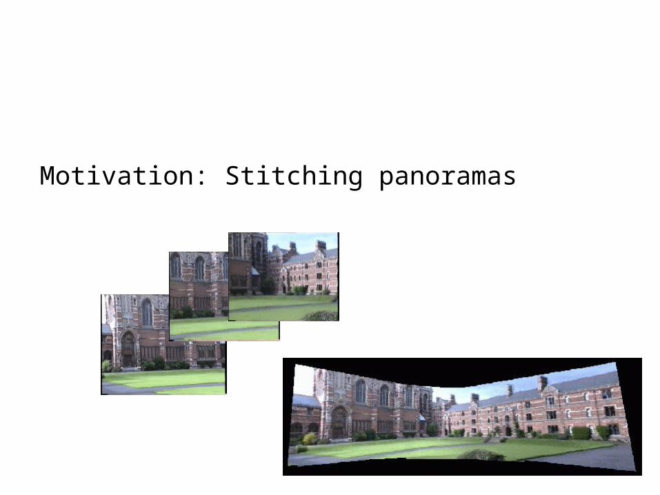
Motivation: Stitching panoramas

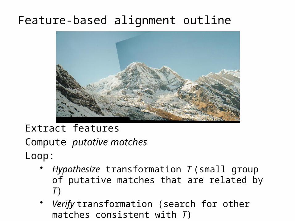
Feature-based alignment outline

Feature-based alignment outline
Extract features

Feature-based alignment outline
Extract features
Compute putative matches

Feature-based alignment outline
Extract features
Compute putative matches
Loop:• Hypothesize transformation T (small group of putative
matches that are related by T)

Feature-based alignment outline
Extract features
Compute putative matches
Loop:• Hypothesize transformation T (small group of putative
matches that are related by T)• Verify transformation (search for other matches
consistent with T)
Feature-based alignment outline
Extract features
Compute putative matches
Loop:• Hypothesize transformation T (small group of putative
matches that are related by T)• Verify transformation (search for other matches
consistent with T)

2D transformation models
Similarity(translation, scale, rotation)
Affine
Projective(homography)
Why these transformations ???

Camera geometry

Images are two-dimensional patterns of brightness values.
They are formed by the projection of 3D objects.

Animal eye: a looonnng time ago.
Pinhole perspective projection: Brunelleschi, XVth Century.Camera obscura: XVIth Century.
Photographic camera:Niepce, 1816.


Massaccio’s Trinity, 1425
Pompei painting, 2000 years ago.
Van Eyk, XIVth Century
Brunelleschi, 1415

Pinhole Perspective Equation
z
yfy
z
xfx
''
''
NOTE: z is always negative..
Camera center
Image plane(retina)
Principal axis
Camera co-ordinate system
€
P = (x,y,z)T
P'= (x',y ')T
€
y'
€
f '
€
z
€
y
€
O
World point
Imagedpoint

Affine projection models: Weak perspective projection
0
'where
'
'
z
fm
myy
mxx
is the magnification.
When the scene relief is small compared its distance from theCamera, m can be taken constant: weak perspective projection.

Affine projection models: Orthographic projection
yy
xx
'
' When the camera is at a(roughly constant) distancefrom the scene, take m=1.

Strong perspective: Angles are not preservedThe projections of parallel lines intersect at one point

From Zisserman & Hartley

Strong perspective: Angles are not preservedThe projections of parallel lines intersect at one point
Weak perspective: Angles are better preservedThe projections of parallel lines are (almost) parallel

Beyond pinhole camera model: Geometric Distortion
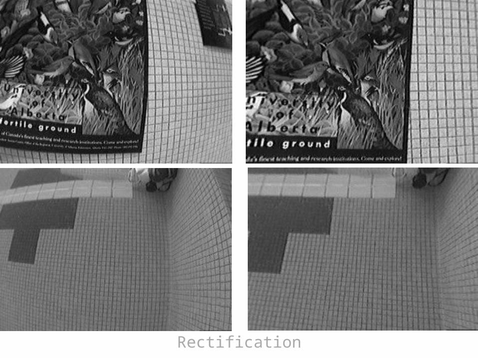
Rectification

Radial Distortion Model

Perspective Projection
x,y: World coordinatesx’,y’: Image coordinatesf: pinhole-to-retina distance
Weak-Perspective Projection (Affine)
x,y: World coordinatesx’,y’: Image coordinatesm: magnification
Orthographic Projection (Affine)
x,y: World coordinatesx’,y’: Image coordinates
Common distortion model
x’,y’: Ideal image coordinatesx’’,y’’: Actual image coordinates
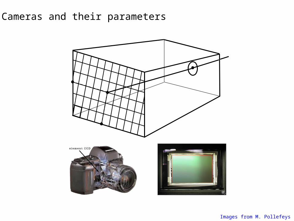
Cameras and their parameters
Images from M. Pollefeys
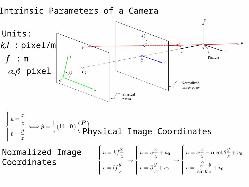
The Intrinsic Parameters of a Camera
Normalized ImageCoordinates
Physical Image Coordinates
Units:k,l : pixel/m
f : m
, a b : pixel

The Intrinsic Parameters of a Camera
Calibration Matrix
The PerspectiveProjection Equation

Notation
Euclidean Geometry

Recall: Coordinate Changes and Rigid Transformations
ABAB
AB OPRP
11111
PT
OPRPORP ABA
ABAB
AA
TA
BBA
B
0

The Extrinsic Parameters of a Camera
€
WP =
W xW yW z
⎛
⎝
⎜ ⎜ ⎜
⎞
⎠
⎟ ⎟ ⎟
€
u
v
1
⎛
⎝
⎜ ⎜ ⎜
⎞
⎠
⎟ ⎟ ⎟=
1
z
m12 m12 m13 m14
m21 m22 m23 m24
m31 m32 m33 m34
⎡
⎣
⎢ ⎢ ⎢
⎤
⎦
⎥ ⎥ ⎥
W xW yW z
1
⎛
⎝
⎜ ⎜ ⎜ ⎜
⎞
⎠
⎟ ⎟ ⎟ ⎟

Explicit Form of the Projection Matrix
Note:
M is only defined up to scale in this setting!!

Weak perspective (affine) camera
€
zr = m3TP = const.
€
u
v
1
⎛
⎝
⎜ ⎜ ⎜
⎞
⎠
⎟ ⎟ ⎟=
1
zr
m1T
m2T
m3T
⎡
⎣
⎢ ⎢ ⎢
⎤
⎦
⎥ ⎥ ⎥P =
m1TP /m3
TP
m2TP /m3
TP
m3TP /m3
TP
⎛
⎝
⎜ ⎜ ⎜
⎞
⎠
⎟ ⎟ ⎟
€
u
v
⎛
⎝ ⎜
⎞
⎠ ⎟=a11 a12 a13 b1
a21 a22 a23 b2
⎡
⎣ ⎢
⎤
⎦ ⎥
W xW yW z
1
⎛
⎝
⎜ ⎜ ⎜ ⎜
⎞
⎠
⎟ ⎟ ⎟ ⎟
=AWP + b
€
b2×1
€
A2×3
€
u
v
⎛
⎝ ⎜
⎞
⎠ ⎟=
1
zr
m1T
m2T
⎡
⎣ ⎢
⎤
⎦ ⎥P

Observations:
is the equation of a plane of normal direction a1
• From the projection equation, it is also the plane defined by: u = 0
• Similarly: • (a2,b2) describes the plane defined by: v = 0• (a3,b3) describes the plane defined by:
That is the plane parallel to image plane passing through the pinhole (z = 0) – principal
plane
Geometric Interpretation
33
11
3
1
b
Z
Y
X
a
b
Z
Y
X
a
Pm
Pmu
T
T
T
T
€
a1T
X
Y
Z
⎡
⎣
⎢ ⎢ ⎢
⎤
⎦
⎥ ⎥ ⎥+ b1 = 0
vu
Projection equation:

u
v
a3
C
Geometric Interpretation: The rows of the projection matrix describe the three planes defined by the image coordinate system
a1
a2

Other useful geometric properties
Principal axis of the camera:The ray passing through the camera centre with direction vector a3
a3
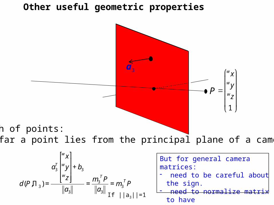
Other useful geometric properties
Depth of points: How far a point lies from the principal plane of a camera?
a3
P
€
d(P,Π 3) =
a3T
w xw ywz
⎡
⎣
⎢ ⎢ ⎢
⎤
⎦
⎥ ⎥ ⎥+ b3
a3
=m3
TP
a3
= m3TP
If ||a3||=1
€
=
w xw ywz
1
⎛
⎝
⎜ ⎜ ⎜ ⎜
⎞
⎠
⎟ ⎟ ⎟ ⎟
But for general camera matrices: - need to be careful about the sign.- need to normalize matrix to have ||a3||=1

p P
Other useful geometric properties
Q: Can we compute the position of the camera center W?
A:
Q: Given an image point p, what is the direction of the corresponding ray in space?
A:
pAw 1
bA 1 Hint: Start from the projection equation. Show that the right null-space of camera matrix M is the camera center.
Hint: Start from a projection equation and write all points along direction w, that project to point p.

Re-cap: imaging and camera geometry(with a slight change of notation)
• perspective projection
• camera centre, image point and scene point are collinear
• an image point back projects to a ray in 3-space
• depth of the scene point is unknown camera
centre image plane
imagepoint
scenepoint
C
X
x
Slide credit: A. Zisserman

Slide credit: A. Zisserman

How a “scene plane” projects into an image?

Plane projective transformations
Slide credit: A. Zisserman

Projective transformations continued
• This is the most general transformation between the world and image plane under imaging by a perspective camera.
• It is often only the 3 x 3 form of the matrix that is important in establishing properties of this transformation.
• A projective transformation is also called a ``homography'' and a ``collineation''.
• H has 8 degrees of freedom.
Slide credit: A. Zisserman

Planes under affine projection
€
x1
x2
⎛
⎝ ⎜
⎞
⎠ ⎟=a11 a12 a13 b1
a21 a22 a23 b2
⎡
⎣ ⎢
⎤
⎦ ⎥
x
y
0
1
⎛
⎝
⎜ ⎜ ⎜ ⎜
⎞
⎠
⎟ ⎟ ⎟ ⎟
=a11 a12
a21 a22
⎡
⎣ ⎢
⎤
⎦ ⎥x
y
⎛
⎝ ⎜
⎞
⎠ ⎟+b1
b2
⎛
⎝ ⎜
⎞
⎠ ⎟= A2×2P + b2×1
Points on a world plane map with a 2D affine geometric transformation (6 parameters)

• Affine projections induce affine transformations from planes
onto their images.
• Perspective projections induce projective transformations from planes onto their images.
Summary

2D transformation models
Similarity(translation, scale, rotation)
Affine
Projective(homography)

When is homography a valid transformation model?

Case I: Plane projective transformations
Slide credit: A. Zisserman

Case II: Cameras rotating about their centre
image plane 1
image plane 2
• The two image planes are related by a homography H
• H depends only on the relation between the image planes and camera centre, C, not on the 3D structure
P = K [ I | 0 ] P’ = K’ [ R | 0 ]
H = K’ R K^(-1)
Slide credit: A. Zisserman

Case II: Cameras rotating about their centre
image plane 1
image plane 2
€
P =K[I | 0] P '=K '[R | 0]
x =K[I | 0]X
1
⎛
⎝ ⎜
⎞
⎠ ⎟=KX ⇒ X =K−1x
x'=K '[R | 0]X
1
⎛
⎝ ⎜
⎞
⎠ ⎟=K 'RX
x'=K 'RK−1
H1 2 3 x
Slide credit: A. Zisserman


![Abstract arXiv:1506.09215v4 [cs.CV] 28 Jun 2016Jean-Baptiste Alayracy Piotr Bojanowski Nishant Agrawal z Josef Sivic Ivan Laptev Simon Lacoste-Julieny Abstract We address the problem](https://img.dokumen.tips/doc/110x75/5f15d401bd8e0375bc119522/abstract-arxiv150609215v4-cscv-28-jun-2016-jean-baptiste-alayracy-piotr-bojanowski.jpg)


![Abstract arXiv:submit/1599949 [cs.CV] 28 Jun 2016 · Jean-Baptiste Alayracy Piotr Bojanowski Nishant Agrawal z Josef Sivic Ivan Laptev Simon Lacoste-Julieny Abstract We address the](https://img.dokumen.tips/doc/110x75/5ec6a7fdf6988e6878798e3e/abstract-arxivsubmit1599949-cscv-28-jun-2016-jean-baptiste-alayracy-piotr-bojanowski.jpg)


![A Virtual Environment with Multi-Robot Navigation ... · References [Aubryet al., 2014] Mathieu Aubry, Daniel Maturana, Alexei A Efros, Bryan C Russell, and Josef Sivic. Seeing 3d](https://img.dokumen.tips/doc/110x75/5e03b06e954676242b3e0d2b/a-virtual-environment-with-multi-robot-navigation-references-aubryet-al-2014.jpg)