Embed Size (px)
Citation preview

Installing, Programming and Commissioning of Power System
Protection Relays and Hardware

WHO ARE WE? IDC Technologies is internationally acknowledged as the premier provider of practical, technical training for engineers and technicians. We specialize in the fields of electrical systems, industrial data communications, telecommunications, automation and control, mechanical engineering, chemical and civil engineering, and are continually adding to our portfolio of over 60 different workshops. Our instructors are highly respected in their fields of expertise and in the last ten years have trained over 200,000 engineers, scientists and technicians. With offices conveniently located worldwide, IDC Technologies has an enthusiastic team of professional engineers, technicians and support staff who are committed to providing the highest level of training and consultancy. TECHNICAL WORKSHOPS TRAINING THAT WORKS We deliver engineering and technology training that will maximize your business goals. In today’s competitive environment, you require training that will help you and your organization to achieve its goals and produce a large return on investment. With our ‘training that works’ objective you and your organization will:
• Get job-related skills that you need to achieve your business goals • Improve the operation and design of your equipment and plant • Improve your troubleshooting abilities • Sharpen your competitive edge • Boost morale and retain valuable staff • Save time and money
EXPERT INSTRUCTORS We search the world for good quality instructors who have three outstanding attributes:
1. Expert knowledge and experience – of the course topic 2. Superb training abilities – to ensure the know-how is transferred effectively and quickly to you in
a practical, hands-on way 3. Listening skills – they listen carefully to the needs of the participants and want to ensure that you
benefit from the experience. Each and every instructor is evaluated by the delegates and we assess the presentation after every class to ensure that the instructor stays on track in presenting outstanding courses. HANDS-ON APPROACH TO TRAINING All IDC Technologies workshops include practical, hands-on sessions where the delegates are given the opportunity to apply in practice the theory they have learnt. REFERENCE MATERIALS A fully illustrated workshop book with hundreds of pages of tables, charts, figures and handy hints, plus considerable reference material is provided FREE of charge to each delegate. ACCREDITATION AND CONTINUING EDUCATION Satisfactory completion of all IDC workshops satisfies the requirements of the International Association for Continuing Education and Training for the award of 1.4 Continuing Education Units. IDC workshops also satisfy criteria for Continuing Professional Development according to the requirements of the Institution of Electrical Engineers and Institution of Measurement and Control in the UK, Institution of Engineers in Australia, Institution of Engineers New Zealand, and others.
THIS BOOK WAS DEVELOPED BY IDC TECHNOLOGIES

CERTIFICATE OF ATTENDANCE Each delegate receives a Certificate of Attendance documenting their experience. 100% MONEY BACK GUARANTEE IDC Technologies’ engineers have put considerable time and experience into ensuring that you gain maximum value from each workshop. If by lunchtime on the first day you decide that the workshop is not appropriate for your requirements, please let us know so that we can arrange a 100% refund of your fee. ONSITE WORKSHOPS All IDC Technologies Training Workshops are available on an on-site basis, presented at the venue of your choice, saving delegates travel time and expenses, thus providing your company with even greater savings. OFFICE LOCATIONS
AUSTRALIA • CANADA • INDIA • IRELAND • MALAYSIA • NEW ZEALAND • POLAND • SINGAPORE • SOUTH AFRICA • UNITED KINGDOM • UNITED STATES
On-Site Training
All IDC Technologies Training Workshops are available on an on-site basis, presented at the venue of your choice, saving delegates travel time and expenses, thus providing your company with even
greater savings. For more information or a FREE detailed proposal contact Kevin Baker by e-mailing:
[email protected] www.idc-online.com
Visit our website for FREE Pocket Guides IDC Technologies produce a set of 6 Pocket Guides used by
thousands of engineers and technicians worldwide. Vol. 1 – ELECTRONICS Vol. 4 – INSTRUMENTATION Vol. 2 – ELECTRICAL Vol. 5 – FORMULAE & CONVERSIONS Vol. 3 – COMMUNICATIONS Vol. 6 – INDUSTRIAL AUTOMATION
To download a FREE copy of these internationally best selling pocket guides go to:
www.idc-online.com/downloads/
SAVE MORE THAN 50% OFF the per person
cost
CUSTOMISE the training to YOUR WORKPLACE!
Have the training delivered WHEN
AND WHERE you need it!

IDC TECHNOLOGIES
Worldwide Offices
AUSTRALIA Telephone: 1300 138 522 • Facsimile: 1300 138 533
West Coast Office
1031 Wellington Street, West Perth, WA 6005 PO Box 1093, West Perth, WA 6872
East Coast Office
PO Box 1750, North Sydney, NSW 2059
CANADA Toll Free Telephone: 1800 324 4244 • Toll Free Facsimile: 1800 434 4045
Suite 402, 814 Richards Street, Vancouver, NC V6B 3A7
INDIA Telephone : +91 444 208 9353
35 4th Street, Kumaran Colony, Vadapalani, Chennai 600026
IRELAND Telephone : +353 1 473 3190 • Facsimile: +353 1 473 3191
Caoran, Baile na hAbhann, Co. Galway
MALAYSIA Telephone: +60 3 5192 3800 • Facsimile: +60 3 5192 3801
26 Jalan Kota Raja E27/E, Hicom Town Center Seksyen 27, 40400 Shah Alam, Selangor
NEW ZEALAND
Telephone: +64 9 263 4759 • Facsimile: +64 9 262 2304 Parkview Towers, 28 Davies Avenue, Manukau City
PO Box 76-142, Manukau City
POLAND Telephone: +48 12 6304 746 • Facsimile: +48 12 6304 750
ul. Krakowska 50, 30-083 Balice, Krakow
SINGAPORE Telephone: +65 6224 6298 • Facsimile: + 65 6224 7922
100 Eu Tong Sen Street, #04-11 Pearl’s Centre, Singapore 059812
SOUTH AFRICA Telephone: +27 87 751 4294 or +27 79 629 5706 • Facsimile: +27 11 312 2150
68 Pretorius Street, President Park, Midrand PO Box 389, Halfway House 1685
UNITED KINGDOM
Telephone: +44 20 8335 4014 • Facsimile: +44 20 8335 4120 Suite 18, Fitzroy House, Lynwood Drive, Worcester Park, Surrey KT4 7AT
UNITED STATES
Toll Free Telephone: 1800 324 4244 • Toll Free Facsimile: 1800 434 4045 5715 Will Clayton #6175, Humble, TX 77338, USA
Website: www.idc-online.com
Email: [email protected]

Presents
Installing, Programming and Commissioning of Power System Protection Relays and Hardware
First edition
Website: www.idc-online.com E-mail: [email protected]
IDC Technologies Pty Ltd PO Box 1093, West Perth, Western Australia 6872 Offices in Australia, New Zealand, Singapore, United Kingdom, Ireland, Malaysia, Poland, United States of America, Canada, South Africa and India Copyright © IDC Technologies 2008. All rights reserved. First published 2008 All rights to this publication, associated software and workshop are reserved. No part of this publication may be reproduced, stored in a retrieval system or transmitted in any form or by any means electronic, mechanical, photocopying, recording or otherwise without the prior written permission of the publisher. All enquiries should be made to the publisher at the address above. Disclaimer Whilst all reasonable care has been taken to ensure that the descriptions, opinions, programs, listings, software and diagrams are accurate and workable, IDC Technologies do not accept any legal responsibility or liability to any person, organization or other entity for any direct loss, consequential loss or damage, however caused, that may be suffered as a result of the use of this publication or the associated workshop and software.
In case of any uncertainty, we recommend that you contact IDC Technologies for clarification or assistance.
Trademarks All logos and trademarks belong to, and are copyrighted to, their companies respectively. Acknowledgements IDC Technologies expresses its sincere thanks to all those engineers and technicians on our training workshops who freely made available their expertise in preparing this manual.

Contents 1 Need for Protection 1
1.1 Need for protective apparatus 1 1.2 Basic requirements of protection 2 1.3 Basic components of protection 2 1.4 The development of simple distribution systems 3 1.5 Faults: types and effects 5 1.6 System grounding 8 1.7 Grounding devices 9 1.8 Fuses 12 1.9 Rewireable type 13 1.10 Cartridge type 13 1.11 Operating characteristics 14 1.12 Governing standards 15 1.13 Energy ‘let through’ 16 1.14 Application of selection of fuses 16 1.15 General ‘rules of thumb’ 17 1.16 Special types 18 1.17 General 18 1.18 Is-limiter 20 1.19 Instrument transformers 22 1.20 Basic theory of operation 23 1.21 Application of current transformers 23
2 Relays and their Development 27 2.1 Introduction 27 2.2 Principle of the construction and operation of the electromechanical IDMTL relay 27 2.3 Factors influencing choice of plug setting 38 2.4 The new era in protection 39 2.5 Universal microprocessor current relay 47 2.6 Bay controllers 48 2.7 Technical features of a modern microprocessor relay 52 2.8 Type testing 62 2.9 Summary of the advantages of microprocessor-based relays 63 2.10 The future of production for distribution systems 64 2.11 The era of the IED 65 2.12 Substation automation 68 2.13 Communication capability 71
3 Protection Coordination 73 3.1 Introduction 73 3.2 What is coordination? 74 3.3 Over-current coordination 75 3.4 Protection design on medium and low voltage networks 80 3.5 Sensitive ground fault protection 100

4 Typical Block Diagram of Numerical Protection Relays 103 4.1 Introduction 103 4.2 Basic approach used in numerical protective relays 104 4.3 Block diagram of a numerical protection relay 107 4.4 Hardware architecture 108 4.5 Relay software 110 4.6 Sampling 110 4.7 Extension of capabilities of relays in numerical design 114 4.8 From individual protection relays to a complete relay protection management system 114 4.9 The era of the IED 116 4.10 Summary 118
5 Different Types of Numerical Protection Systems 119
5.1 Introduction 119 5.2 Different types of relays 120 5.3 Functional protective relays 120 5.4 Equipment protection relays 125 5.5 Summary 147
6 Configuration of Numerical Relays 149
6.1 Introduction 149 6.2 Setting approach in conventional relays 149 6.3 Configuring numerical relays 150 6.4 Configuration security through passwords 154 6.5 Protection settings as part of a configuration 155 6.6 Methods adopted for setting numerical relays 162 6.7 Examples of front panel configuration sequence 163 6.8 Configuration exercises for typical relays/simulation software 168 6.9 Summary 172
7 Communications Aspects of Numerical Protection Devices 173 7.1 Introduction 173 7.2 The remote terminal unit 173 7.3 Programmable logic controllers 174 7.4 Protection relays 175 7.5 The IED 175 7.6 Configuration 178 7.7 Communication requirements 178 7.8 Example of requirements 184 7.9 IEC 61850 185 7.10 Benefits of IEC 61850 185 7.11 GOOSE 186
Appendix A SIPROTEC4 7UTG Transformer Differential Relay 189 Appendix B SIPROTEC4 7SA6 Distance Protection Relay 197 Appendix C SIPROTEC4 7SJ64 Feeder Management Relay 207

Appendix D SIPROTEC4 7SD61 Line Differential Relay 215 Appendix E SIPROTEC4 7SS60 Feeder Management System 225 Appendix F Exercises 231


1 Need for Protection
Important notes 1. This book was originally written for UK and other European users and contains many
references to the products and standards in those countries. We have made an effort to include IEEE/ANSI/NEMA references wherever possible. The general protection approach and theoretical principles are however universally applicable.
2. The terms ‘earth’ as well as ‘ground’ have both been in general use to describe the common power/signal reference point interchangeably around the world in the Electro-technical terminology. While the USA and other North American countries favor the use of the term ‘ground’, European countries including UK and many other Eastern countries prefer the term ‘earth’. In this book, we will adopt the term ‘ground’ to denote the common electrical reference point. Our sincere apologies to those readers who would have preferred the use of ‘earth’ to the term ‘ground’.
1.1 Need for protective apparatus A power system must be not only capable of meeting the present load but also requires the flexibility to meet the future demand. A power system is designed to generate electric power in sufficient quantity, to meet the present and estimated future demands of the users in a particular area, to transmit it to the areas where it will be used and then distribute it within that area, on a continuous basis. To ensure the maximum return on the significant investment in the equipment, which goes to make up the power system, and to keep the users satisfied with reliable service, the whole system must be kept in operation continuously without major breakdowns.
This can be achieved in two ways:
• The first option is to implement a system using components, which should not fail and which require minimal maintenance to maintain the continuity of service. However, implementing such a system is neither economical nor feasible, except for small systems.
• The second option is to anticipate any possible effects or failures that may cause a
long-term shutdown of a system, which in turn may take a longer time to bring the system back to its normal operation. The main idea is to restrict the disturbances during such failures to a limited area and maintain power distribution to the remaining areas. Special equipment is normally installed to detect such kind of failures (also
2 Installing, Programming and Commissioning of Power System Protection Relays and Hardware
called ‘faults’) that can possibly happen in various sections of a system, and to isolate faulty sections so that the interruption is limited to a localized area. The special equipment adopted to detect such possible faults is referred to as ‘Protective equipment or a protective relay’ and the system that uses such equipment is termed a ‘Protection system’.
A protective relay is the device, which gives instruction to disconnect a faulty part of the system. This action ensures that the remaining system is still fed with power, and protects the system from further damage due to the fault. Hence, use of protective apparatus is very necessary in the electrical systems, which are expected to generate, transmit and distribute power with least interruptions and restoration time.
1.2 Basic requirements of protection A protection system has three main functions/duties:
• Safeguard the entire system to maintain continuity of supply. • Minimize damage and repair costs where it senses a fault. • Ensure safety of personnel.
These requirements are necessary, firstly for early detection and localization of faults and secondly, prompt removal of faulty equipment from service.
In order to carry out the above duties, protection must have the following qualities:
a) Selectivity: To detect and isolate the faulty item only.
b) Stability: To leave all healthy circuits intact to ensure continuity of supply.
c) Sensitivity: To detect even the smallest fault, current or system abnormalities and operate correctly at its setting before the fault causes irreparable damage.
d) Speed: To operate speedily when it is called upon to do so, thereby minimizing damage to the surroundings and ensuring safety to personnel.
To meet all of the above requirements, protection must be reliable which means it must be: • Dependable - it must trip when called upon to do so.
• Secure - it must not trip when it is not supposed to.
1.3 Basic components of protection The protection of any distribution system is a function of many elements and this section gives a brief outline of the various components that go into protecting a system. The following are the main components of a protection system.
• A fuse self destructs and carries the currents in a power circuit continuously and sacrifices itself by blowing under abnormal conditions. These are normally independent OR stand-alone protective components in an electrical system unlike a circuit breaker, which necessarily requires the support of external components.
• Accurate protection cannot be achieved without properly measuring the normal and abnormal conditions of a system. In electrical systems, voltage and current measurements give feedback on whether a system is healthy or not. Voltage transformers and current transformers measure these basic parameters and are capable of providing accurate measurement during fault conditions without failure.
• The measured values are converted into analog and/or digital signals and are made to operate the relays, which in turn isolate the circuits by opening the faulty circuits. In most of the cases, the relays provide two functions: alarm and trip; once the abnormality is noticed. The relays in earlier times had very limited functions and were

Need for Protection 3
quite bulky. However, with the advancement in digital technology and use of microprocessors, relays monitor various parameters, which give a complete history of a system during both pre-fault and post-fault conditions.
• The opening of faulty circuits requires some time, typically milliseconds. However, the circuit breakers, which are used to isolate the faulty circuits, are capable of carrying these fault currents until the fault currents are totally cleared. The circuit breakers are the main isolating devices in a distribution system, which can be said to directly protect the system.
• The operation of relays and breakers require power sources, which shall not be affected by faults in the main distribution. Hence, the other component, which is vital in protective system, are batteries that are used to ensure uninterrupted power to relays and breaker coils.
The above items are extensively used in any protective system and their design requires careful study and selection for proper operation.
1.4 The development of simple distribution systems When a consumer requests electrical power from a supply authority, ideally all that is required is a cable and a transformer, shown physically as in Figure 1.1:
Figure 1.1
A simple distribution system
This is called a Radial system and can be shown schematically in the following manner (Figure 1.2.)
Figure 1.2 A radial distribution system
Advantages If a fault occurs at T2 then only the protection on one leg connecting T2 is called into operation to isolate this leg. The other consumers are not affected.
Disadvantages If the conductor to T2 fails, then supply to this particular consumer is lost completely and cannot be restored until the conductor is replaced/repaired.

4 Installing, Programming and Commissioning of Power System Protection Relays and Hardware
This disadvantage can be overcome by introducing additional/parallel feeders (Figure 1.3) connecting each of the consumers radially. However, this requires more cabling and is not always economical. The fault current also tends to increase due to use of two cables.
Figure 1.3 Radial distribution system with parallel feeders
The Ring main system, which is the most favored, then came into being (Figure 1.4). Here each consumer has two feeders but connected in different paths to ensure continuity of power, in case of conductor failure in any section.
Figure 1.4 A ring main distribution system
Advantages
Essentially, meets the requirements of two alternative feeds to give 100% continuity of supply, whilst saving in cabling/copper compared to parallel feeders.
Disadvantages
For faults at T1 fault current is fed into fault via two parallel paths effectively reducing the impedance from the source to the fault location, and hence the fault current is much higher compared to a radial path. The fault currents in particular could vary depending on the exact location of the fault. Protection must therefore be fast and discriminate correctly, so that other consumers are not interrupted. The above case basically covers feeder failure, since cables tend to be the most vulnerable component in the network. Not only are they likely to be hit by a pick or alternatively dug-up, or crushed by heavy machinery, but their joints are notoriously weak, being susceptible to moisture, ingress, etc. amongst other things.

Need for Protection 5
Transformer faults are not so frequent, however they do occur as windings are often strained when carrying fault currents. Also, their insulation lifespan is very often reduced due to temporary or extended overloading leading to eventual failure. Hence interruption or restriction in the power being distributed cannot be avoided in case of transformer failures. As it takes a few months to manufacture a power transformer, it is a normal practice to install two units at a substation with sufficient spare capacity to provide continuity of supply in case of transformer failure. Busbars on the other hand, are considered to be the most vital component on a distribution system. They form an electrical ‘node’ where many circuits come together, feeding in and sending out power. On E.H.V. systems where mainly outdoor switchgear is used, it is relatively easy and economical to install duplicate busbar system to provide alternate power paths. But on medium voltage (11 kV, 6.6 kV and 3.3kV) and low voltage (1000 V and 500 V) systems, where indoor metal clad switchgear is extensively used, it is not practical or economical to provide standby or parallel switchboards. Further, duplicate busbar switchgear is not immune to the ravages of a busbar fault. The loss of a busbar in a network can in fact be a catastrophic situation, and it is recommended that this component be given careful consideration from a protection viewpoint when designing the network, particularly for continuous process plants such as mineral processing.
1.5 Faults: types and their effects It is not practical to design and build electrical equipment or networks to eliminate the possibility of failure in service. Faults can be broadly classified into two main areas, which have been designated ‘Active’ and ‘Passive’.
1.5.1 Active faults The ‘Active’ fault is when actual current flows from one phase conductor to another (phase-to-phase), or alternatively from one phase conductor to ground (phase-to-ground). This type of fault can also be further classified into two areas, namely the ‘solid’ fault and the ‘incipient’ fault. The solid fault occurs as a result of an immediate complete breakdown of insulation as would happen if, say, a pick struck an underground cable, bridging conductors etc. or the cable was dug up by a bulldozer. In mining, a rockfall could crush a cable, as would a shuttle car. In these circumstances the fault current would be very high, resulting in an electrical explosion. This type of fault must be cleared as quickly as possible, otherwise there will be:
• Increased damage at fault location. Fault energy = I2 × Rf × t where t is time in seconds.
• Danger to operating personnel (flashes due to high fault energy sustaining for a long time).
• Danger of igniting combustible gas in hazardous areas, such as methane in coal mines which could cause horrendous disaster.
• Increased probability of ground faults spreading to healthy phases.
• Higher mechanical and thermal stressing of all items of plant carrying the fault current, particularly transformers whose windings suffer progressive and cumulative deterioration because of the enormous electro-mechanical forces caused by multiphase faults proportional to the square of the fault current.
• Sustained voltage dips resulting in motor (and generator) instability leading to extensive shutdown at the plant concerned and possibly other nearby plants connected to the system.

6 Installing, Programming and Commissioning of Power System Protection Relays and Hardware
The ‘incipient’ fault, on the other hand, is a fault that starts in a small way and develops into catastrophic failure. For example, partial discharge (excessive discharge activity is often referred to as a Corona) occurring in a void in the insulation over an extended period can burn away adjacent insulation, eventually spreading further and developing into a ‘solid’ fault. Other causes can typically be a high-resistance joint or contact, alternatively pollution of insulators causing tracking across their surface. Once tracking occurs, any surrounding air will ionise and then behaves like a solid conductor consequently creating a ‘solid’ fault.
1.5.2 Passive faults Passive faults are not real faults in the true sense of the word, but are rather conditions that are stressing the system beyond its design capacity, so that ultimately active faults will occur. Typical examples are:
• Over loading leading to over heating of insulation (deteriorating quality, reduced life and ultimate failure)
• Over voltage—Stressing the insulation beyond its withstand capacities
• Under frequency—Causing plant to behave incorrectly
• Power swings—Generators going out-of-step or out-of-synchronism with each other
It is therefore necessary to monitor these conditions to protect the system against these conditions.
1.5.3 Types of faults on a three-phase system Largely, the power distribution is globally a three-phase distribution especially from power sources. The types of faults that can occur on a three-phase A.C. system are shown in Figure 1.5.
(A) Phase-to-ground fault (B) Phase-to-phase fault (C) Phase-to-phase-to-ground fault (D) Three-phase fault (E) Three-phase-to-ground fault (F) Phase-to-pilot fault* (G) Pilot-to-ground fault* * In underground mining applications only
Figure 1.5 Types of faults on a three-phase system
It will be noted that for a phase-to-phase fault, the currents will be high, because the fault current is only limited by the inherent (natural) series impedance of the power system up to the point of fault (Ohm’s law).
Need for Protection 7
By design, this inherent series impedance in a power system is purposely chosen to be as low as possible in order to get maximum power transfer to the consumer so that unnecessary losses in the network are limited thereby increasing the distribution efficiency. Hence, the fault current cannot be decreased without a compromise on the distribution efficiency and further reduction cannot be substantial. On the other hand, the magnitude of ground fault currents will be determined by the manner in which the system neutral is grounded. It is worth noting at this juncture that it is possible to control the level of ground fault current that can flow by the judicious choice of grounding arrangements for the neutral. Solid neutral grounding means high ground fault currents, being limited by the inherent ground fault (zero sequence) impedance of the system, whereas additional impedance introduced between neutral and ground can result in comparatively lower ground fault currents. In other words, by the use of resistance or impedance in the neutral of the system, ground fault currents can be engineered to be at whatever level desired, and are therefore controllable. This cannot be achieved for phase faults.
1.5.4 Transient and permanent faults Transient faults are faults, which do not damage the insulation permanently and allow the circuit to be safely re-energized after a short period. A typical example would be an insulator flashover following a lightning strike, which would be successfully cleared on opening of the circuit breaker, which could then be automatically closed. Transient faults occur mainly on outdoor equipment where air is the main insulating medium. Permanent faults, as the name implies, are the result of permanent damage to the insulation. In this case, the equipment has to be repaired and recharging must not be entertained before repair/restoration.
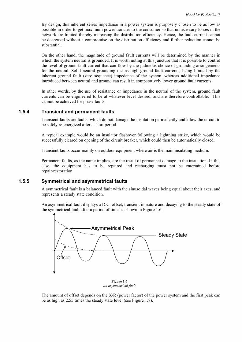
1.5.5 Symmetrical and asymmetrical faults A symmetrical fault is a balanced fault with the sinusoidal waves being equal about their axes, and represents a steady state condition. An asymmetrical fault displays a D.C. offset, transient in nature and decaying to the steady state of the symmetrical fault after a period of time, as shown in Figure 1.6.
Figure 1.6 An asymmetrical fault
The amount of offset depends on the X/R (power factor) of the power system and the first peak can be as high as 2.55 times the steady state level (see Figure 1.7).

8 Installing, Programming and Commissioning of Power System Protection Relays and Hardware
Figure 1.7 Total asymmetry factor chart
1.6 System grounding Sometimes the phase to ground faults in a system can limit the ground fault current depending on adding external impedance between neutral and the ground. This chapter briefly covers the various methods of grounding that are adopted in the electrical systems. In the following sections, the star connected transformer is shown. This is widely used in power distribution. The grounding methods are also applicable to the case of generators, whose windings are also invariably star connected. Table 1.1 highlights the possible problems that can occur in a system due to the common faults and the solutions that can be achieved by adopting system grounding.
Need for Protection 9
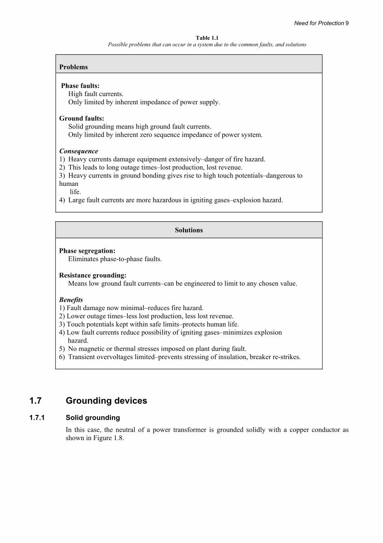
Table 1.1 Possible problems that can occur in a system due to the common faults, and solutions
Problems Phase faults: High fault currents. Only limited by inherent impedance of power supply. Ground faults: Solid grounding means high ground fault currents. Only limited by inherent zero sequence impedance of power system. Consequence 1) Heavy currents damage equipment extensively–danger of fire hazard. 2) This leads to long outage times–lost production, lost revenue. 3) Heavy currents in ground bonding gives rise to high touch potentials–dangerous to human life. 4) Large fault currents are more hazardous in igniting gases–explosion hazard.
Solutions
Phase segregation: Eliminates phase-to-phase faults. Resistance grounding: Means low ground fault currents–can be engineered to limit to any chosen value. Benefits 1) Fault damage now minimal–reduces fire hazard. 2) Lower outage times–less lost production, less lost revenue. 3) Touch potentials kept within safe limits–protects human life. 4) Low fault currents reduce possibility of igniting gases–minimizes explosion hazard. 5) No magnetic or thermal stresses imposed on plant during fault. 6) Transient overvoltages limited–prevents stressing of insulation, breaker re-strikes.
1.7 Grounding devices
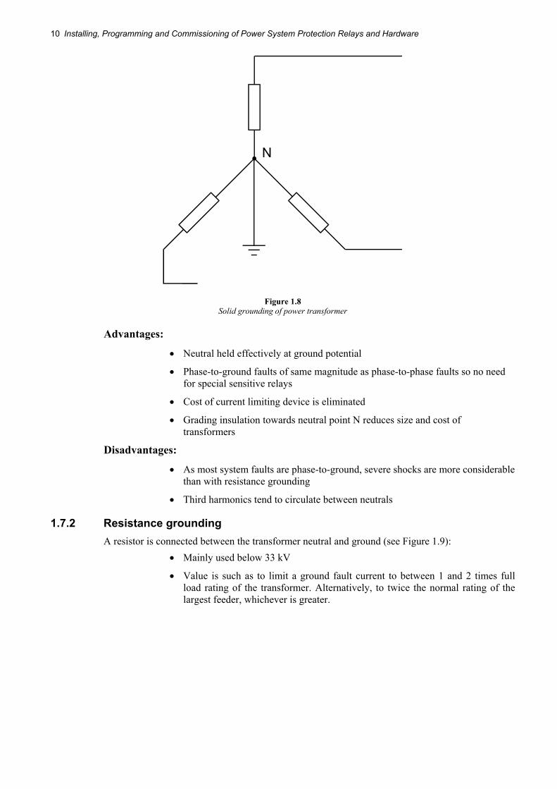
1.7.1 Solid grounding In this case, the neutral of a power transformer is grounded solidly with a copper conductor as shown in Figure 1.8.
10 Installing, Programming and Commissioning of Power System Protection Relays and Hardware
Figure 1.8 Solid grounding of power transformer
Advantages:
• Neutral held effectively at ground potential
• Phase-to-ground faults of same magnitude as phase-to-phase faults so no need for special sensitive relays
• Cost of current limiting device is eliminated
• Grading insulation towards neutral point N reduces size and cost of transformers
Disadvantages:
• As most system faults are phase-to-ground, severe shocks are more considerable than with resistance grounding
• Third harmonics tend to circulate between neutrals
1.7.2 Resistance grounding A resistor is connected between the transformer neutral and ground (see Figure 1.9):
• Mainly used below 33 kV
• Value is such as to limit a ground fault current to between 1 and 2 times full load rating of the transformer. Alternatively, to twice the normal rating of the largest feeder, whichever is greater.

Need for Protection 11
Figure 1.9 Resistance grounding
Advantages:
• Limits electrical and mechanical stress on system when a ground fault occurs, but at the same time, current is sufficient to operate normal protection equipment
Disadvantages:
• Full line-to-line insulation required between phase and ground
1.7.3 Reactance grounding A reactor is connected between the transformer neutral and ground (see Figure 1.10):
• Values of reactance are approximately the same as used for resistance grounding
• To achieve the same value as the resistor, the design of the reactor is smaller and thus cheaper
Figure 1.10 Reactance grounding
1.7.4 Arc suppression coil (Petersen coil) A tunable reactor is connected in the transformer neutral to ground (see Figure 4.4):

12 Installing, Programming and Commissioning of Power System Protection Relays and Hardware
• Value of reactance is chosen such that reactance current neutralizes capacitance current. The current at the fault point is therefore theoretically nil and unable to maintain the arc, hence its name.
• Virtually fully insulated system, hence current available to operate protective equipment is so small as to be negligible. To offset this, the faulty section can be left in service indefinitely without damage to the system as most faults are ground faults of a transient nature, the initial arc at the fault point is extinguished and does not re-strike.
Figure 1.11 Arc suppression coil (Petersen coil)
Sensitive watt-metrical relays are used to detect permanent ground faults.
1.7.5 Grounding via neutral grounding compensator This provides a ground point for a delta system and combines the virtues of resistance and reactance grounding in limiting ground fault current to safe reliable values (see Figure 1.12).
Figure 1.12 Grounding via neutral grounding compensator
1.8 Fuses The fuse is the most common and widely used protective device in electrical circuits. Although the ‘fuse-less’ concept has been growing in importance for quite some time, a lot of low voltage
Need for Protection 13
distribution circuits are still protected with fuses. Fuses also form a major backup for protection in medium voltage and high voltage distribution to 11 kV, where switches and contactors with limited short circuit capacities are used. In 1881, Edison patented his ‘Lead safety wire’, which was officially recognized as the first fuse. However, it was also said that Swan actually used this device in late 1880 in the lighting circuits of Lord Armstrong’s house. He used strips of tin-foil jammed between brass blocks by plugs of woods. The application of the fuse in those days was not to protect the wires and system against short-circuit, but to protect the lights which cost 25 shillings a time (a fortune in those days). Later, as electrical distribution systems grew, it was found that after short circuits, certain conductors failed. This was due to the copper conductors, not being accurately drawn out (extruded) to a constant diameter throughout the cable length; faults always occurring at the smallest cross-sectional area. Fuses were often considered casual devices until quite recently. The open tin-foil (re-wireable) fuse sometimes came in for a lot of abuse. If it blew constantly, then the new fuse was just increased in size until it stayed in permanently. Sometimes hairpins were used. Greater precision only became possible with the introduction of the Cartridge fuse.
1.9 Re-wireable type As the name indicates the fuse can be replaced or ‘rewired’ once it fails. Fusible wire used to be contained in an asbestos tube to prevent splashing of volatile metal. Disadvantages include:
1) Open to abuse due to incorrect rating of replacement elements hence affording incorrect protection
2) Deterioration of element as it is open to the atmosphere
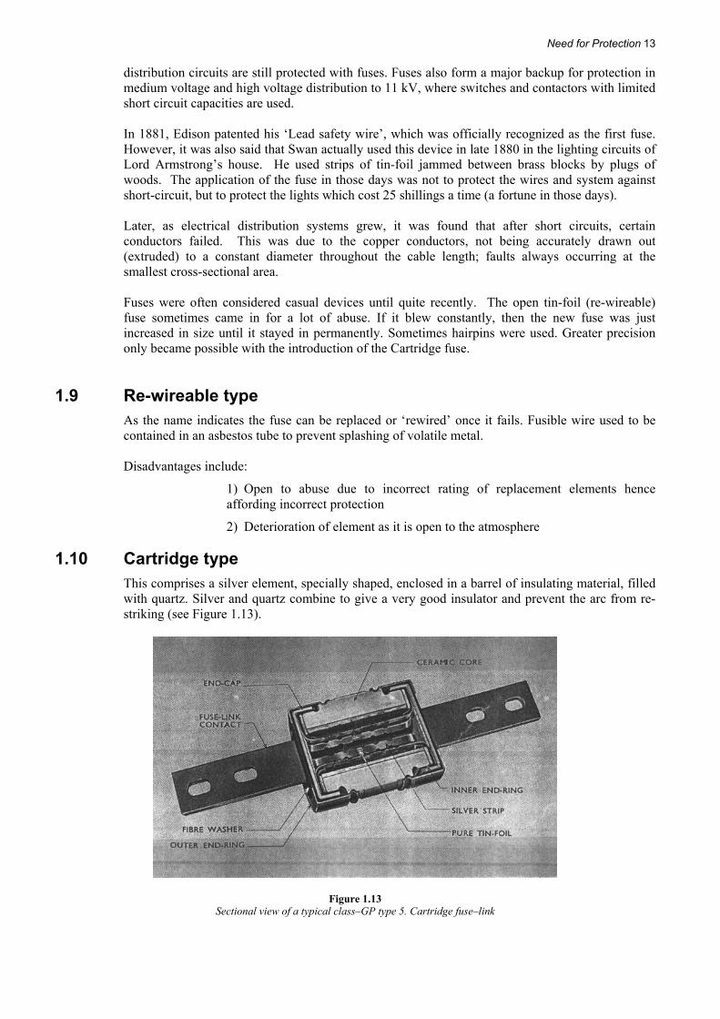
1.10 Cartridge type This comprises a silver element, specially shaped, enclosed in a barrel of insulating material, filled with quartz. Silver and quartz combine to give a very good insulator and prevent the arc from re-striking (see Figure 1.13).
Figure 1.13 Sectional view of a typical class–GP type 5. Cartridge fuse–link

14 Installing, Programming and Commissioning of Power System Protection Relays and Hardware
Advantages include:
1) Correct rating and characteristic fuse always fitted to a circuit - not open to abuse as re-wireable type.
2) Arc and fault energy contained within insulating tube-prevents damage.
3) Normally sealed therefore not affected by atmosphere hence gives more stable characteristic-reliable grading.
4) Can operate considerably faster, suitable for higher short circuit duty:
- Cartridge type can handle 100,000 amps
- Semi-open type can handle 4,000 amps Normal currents carried continuously are much closer to fusing current due to special design of element. These fuses are most widely used in electrical systems and are referred to as HRC (High rupturing capacity) fuses, with the name synonymous with their short circuit current breaking capacity. In North American terminology, these fuses go by the name of cartridge fuses.
1.11 Operating characteristics All fuses irrespective of the type have inverse characteristic as shown in the graph that follows. Inverse means that they can withstand their nominal current rating almost indefinitely but as the currents increases their withstanding time starts decreasing making them ‘blow’. The blowing time decreases as the flowing currents increase. The thermal characteristic or withstand capacity of a fuse is indicated in terms of ‘I2 t’ where I is the current and t is the withstand time (see Figure 1.14). The prospective current is the Irms that would flow on the making of a circuit when the circuit is equipped for insertion of a fuse but that the fuse is replaced with a solid link. The curves are very important when determining the application of fuses as they allow the correct ratings to be chosen to give grading.

Need for Protection 15
Figure 1.14 Inverse characteristic of fuse
1.12 Governing standards Low Voltage cartridge type fuses are governed by various national and international standards; examples being IEC 60269, BS 88, BS EN 60269, NEMA standard FU 1:2002, etc. The standards aim at bringing uniformity in respect of various ratings and operating parameters and other aspects such as overall dimensions, interchangeability etc. For example, British standard BS 88 lays down definite limits of:
a) Temperature rise
b) Fusing factor = 4.1RatingCurrent
CurrentFusingMinimum=
c) Breaking capacity These are all dependent on one another and by careful balancing of factors a really good fuse can be produced. For example, a cool working fuse may be obtained at the expense of breaking capacity. Alternatively, too low a fusing factor may result in too high a temperature, therefore too close protection and possibilities of blowing are more. Another popular standard adopted in North America is NEMA standard document FU 1:2002. This standard categorizes the fuses based on their performance requirements and specifies the voltage/current ratings for different categories. It also specifies the dimensions (derived from FPS system) for each category of fuse and indicates the ferrule/blade details for the fuse where it

16 Installing, Programming and Commissioning of Power System Protection Relays and Hardware
connects with the fuse holder or other external means of connection so as to ensure interchangeability between fuses manufactured by different vendors. NEMA LV fuses have voltage ratings of 60V, 125V, 160V, 250V, 300V, 400V, 500V and 600V (AC RMS). Fuses are categorized under classes G, H, J, K, L, R, T and CC based on their current/voltage/interrupting ratings. The standard also stipulates the maximum temperature rise permissible over the ambient temperature and indicates exact details of measuring the temperature. Details of overload and short circuit tests are also specified.
1.13 Energy ‘let through’ Fuses operate very quickly and can cut-off fault current long before it reaches its first peak (see Figure 1.15):
Figure 1.15 Energy ‘let through’
If a fuse cuts off in the first quarter cycle, then the power let-through is I²t. By comparison, circuit breakers can clear faults in any time up to 10 cycles and in this case the power let-through is the summation of I2 for 10 cycles. The energy released at the fault is therefore colossal compared with that let through by a fuse. Damage is therefore extensive. In addition, all apparatus carrying this fault current (transformers etc) is subjected to high magnetic forces proportional to the fault current squared (If
2)!!
1.14 Application of selection of fuses The fuses blow in cases where the currents flowing through them last for more than its withstand time. This property limits the use of fuses in circuits where the inrush currents are quite high and flow for considerable time such as motors, etc., which draw more than 6 times their full load current for a short time ranging from milli seconds to few seconds depending on the capacity. Hence, it is not possible to use fuses as over load protection in such circuits, since it may be necessary to select a higher rated fuse to withstand inrush currents. Accordingly, the fuses are mostly used as short circuit protection rather than as over load protection in such circuits. The fuses can be used as either for overload and short circuit protection or for short circuit protection as noted below:
• Circuits where the load does not vary much above normal value during switching on and operating conditions. Resistive circuits such as lamps show such characteristics. Hence, it is possible to use fuses as overload protection in such circuits. They also protect against short circuits.
Need for Protection 17
• Circuits where loads vary considerably compared to the normal rating e.g. - Direct-on-line motors - Cranes - Rolling mills - Welding sets, etc. In these cases, fuses are used to provide short-circuit protection
only as it is not possible to select a size meeting both overload and inrush conditions.
Fuse selection depends on a number of factors:
• Maximum fault kVA of circuit to be protected • Voltage of circuit
The above factors help to calculate the prospective current of circuit to be protected. The full prospective current is usually never reached due to rapid operation of the fuse and hence the following factors need to be considered.
(1) Full load current of circuit
Short circuit tests show that the cut-off current increases as the rating increases. Hence if a higher rated fuse is used it may take longer to blow under short circuits which may affect the system depending upon the value and duration. Hence, a greater benefit is derived from the use of correct or the nearest rating of cartridge fuses compared to the circuit rating.
(2) Degree of overcurrent protection required
It is necessary to consider slightly higher ratings for the fuses compared to the maximum normal current expected in a system. This factor is called the fusing factor (Refer to section 5.5) and can be anywhere between 1.25 to 1.6 times the normal rating.
(3) The level of overcurrent required to be carried for a short time without blowing or deteriorating e.g. motor starting currents
This point is important for motor circuits. Fuses must be able to carry starting surge without blowing or deteriorating.
(4) Whether fuses are required to operate or grade in conjunction with other protective apparatus. This factor is necessary to ensure that only faulty circuits are isolated during fault conditions without disturbing the healthy circuits. Depending on the configuration used, discrimination must be achieved between:
- Fuses and fuses
- Fuses and relays, etc. There is no general rule laid down for the application of fuses and each problem must be considered on its own merits.
1.15 General ‘rules of thumb’
1.15.1 Short circuit protection Transformers, fluorescent lighting circuits Transient switching surges - take next highest rating above full load current.
Capacitor circuits Select fuse rating of 25% or greater than the full load rating of the circuit to allow for the extra heating by capacitance effect.
Motor circuits Starting current surge normally lasts for 20 seconds. Squirrel cage induction motors:

18 Installing, Programming and Commissioning of Power System Protection Relays and Hardware
- Direct-on-line takes about 7 times full load current
- 75% tap autotransformer takes about 4 times full load current
- 60% tap autotransformer takes about 2.5 times full load current
- Star/delta starting takes about 2.5 times full load current
1.15.2 Overload protection Recommend 2:1 ratio to give satisfactory discrimination.
1.16 Special types
1.16.1 Striker pin This type is most commonly used on medium and low voltage circuits. When the fuse blows, a striker pin protrudes out of one end of the cartridge. This is used to hit a tripping mechanism on a three-phase switch-fuse unit, so tripping all three-phases. This prevents single phasing on three-phase motors. Note: On switch fuse L.V. distribution gear, it is a good policy to have an isolator on the incoming side of the fuse to facilitate changing.
1.16.2 Drop-out type Used mainly on rural distribution systems. Drops out when fuse blows, isolating the circuit and giving line patrolman easy indication of fault location.
1.17 General The fuse acts as both a fault detector and interrupter. It is satisfactory and adequate for both of these functions in many applications. Its main virtue is speed. However, as a protective device it does have a number of limitations, the more important of which are as follows:
• It can only detect faults that are associated with excess current. • Its operating characteristic (i.e. current/time relationship) cannot be adjusted or set. • It requires replacement after each operation. • It can be used only at low and medium voltages.
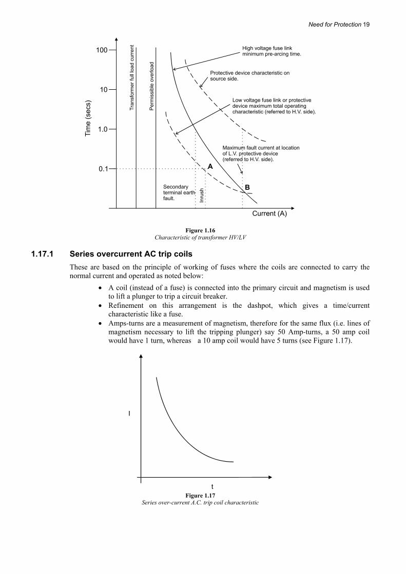
Because of these limitations, fuses are normally used only on relatively unimportant, small power, low and/or medium voltage circuits (see Figure 1.16).
Need for Protection 19
Figure 1.16 Characteristic of transformer HV/LV
1.17.1 Series overcurrent AC trip coils These are based on the principle of working of fuses where the coils are connected to carry the normal current and operated as noted below:
• A coil (instead of a fuse) is connected into the primary circuit and magnetism is used to lift a plunger to trip a circuit breaker.
• Refinement on this arrangement is the dashpot, which gives a time/current characteristic like a fuse.
• Amps-turns are a measurement of magnetism, therefore for the same flux (i.e. lines of magnetism necessary to lift the tripping plunger) say 50 Amp-turns, a 50 amp coil would have 1 turn, whereas a 10 amp coil would have 5 turns (see Figure 1.17).
Figure 1.17
Series over-current A.C. trip coil characteristic

20 Installing, Programming and Commissioning of Power System Protection Relays and Hardware
Limitation of this type of arrangement is:
Thermal rating
This coil must carry the full fault current and if this is high then the heating effect (I²) may be so great as to burn out the insulation. The design must therefore be very conservative.
Magnetic stresses High fault currents induce tremendous magnetic forces inside the trip coil tending to force the windings apart. Here again the design must display a large margin of support and clamping to contain such stresses.
1.18 IS-limiter A very ‘special’ type of fuse is the IS-limiter, originally developed by the company ABB. The device consists of two main current conducting parts, namely the Main conductor and the Fuse, as illustrated in Figure 1.18.
Figure 1.18 Construction of IS-limiter
The device functions as an ‘intelligent fuse’, as illustrated in Figure 1.19. The functional parts are the following:
1. Current transformer (detects the short-circuit current)
2. Measuring and tripping device (measures the current and provides the triggering energy)
3. Pulse transformer (converts the tripping pulse to busbar potential)
4. Insert holder with insert (conducts the operating current and limits the short-circuit current)
The IS-limiter is intended to interrupt very high short-circuit currents very quickly, in order to protect the system against these high currents. Currents of values up to 210 kA (11 kV) can be interrupted in 1 ms. This means that the fault current is interrupted very early in the first cycle, as illustrated in Figure 1.19.

Need for Protection 21
1
2
3
4
Figure 1.19
Functional diagram of IS-limiter
t
Short-circuitcurrent limited bythe fuse element
Figure 1.20 Fault current cycle
When a fault current is detected, the main conductor is opened very swiftly. The current then flows through the fuse, which interrupts the fault current. The over voltage occurring due to the interruption of current is relatively low due to the fact that the magnitude of current on the instant of interruption is still relatively low. The main conductor and parallel fuse have to be replaced after each operation. The IS-limiter is only intended to interrupt high fault currents, leaving the lower fault currents to be interrupted by the circuit breakers in the system. This is achieved by the measuring device detecting the instantaneous current level and the rate of current rise. The rate of current rise (di/dt), is high with high fault currents, and lower with lower fault currents, as illustrated in Figure 1.21. The IS-limiter only trips when both set response values are reached. A practical use of the IS-limiter is illustrated in Figure 1.22, where the combined fault current supplied by two transformers in parallel would be too high for the switchgear panel to withstand.

22 Installing, Programming and Commissioning of Power System Protection Relays and Hardware
I
t
Figure 1.21 Rate of current rise
126 kA
63 kA
t
I
(25 kA x x 2)c
T T1 2k
k
= 25 kA = 25 kA
kperm.= 25 kAI = I + I
I = I + I
I = I + I
I = I + I
1
1
1
1
2
2
1
2
2
2
2
I
I
I
without I -limiter
with I -limiter
s
s
Currentat the short-circuit point
Single linediagram of a bus tiefor a system withI =25 kAand with an I -limiters
Figure 1.22 Practical use of IS-limiter
Here I2 is interrupted first thereby decreasing the fault current to the value of I1 and I1 is interrupted subsequently. The net resultant fault current follows the path of I1 once the limiter functions thereby limiting the overall fault current.
1.19 Instrument transformers The voltage transformers and current transformers continuously measure the voltage and current of an electrical system and are responsible to give feedback signals to the relays to enable them to detect abnormal conditions. The value of actual currents in modern distribution systems vary from a few amperes in households, small industrial/commercial houses, etc., to thousands of amperes in

Need for Protection 23
power intensive plants, national grids, etc., which also depend on the operating voltages. Similarly, the voltages in electrical systems vary from few hundred volts to many kV. However, it is impossible to have monitoring relays designed and manufactured for each and every distribution system and to match the innumerable voltages and currents present. Hence the voltage transformers and current transformers are used which enable same types of relays to be used in all types of distribution systems ensuring the selection and cost of relays to be within manageable ranges.
The main tasks of instrument transformers are:
• To transform currents or voltages from usually a high value to a value easy to handle for relays and instruments.
• To insulate the relays, metering and instruments from the primary high voltage system.
• To provide possibilities of standardizing the relays and instruments, etc. to a few rated currents and voltages.
Instrument transformers are special versions of transformers in respect of measurement of current and voltages. The theories for instrument transformers are the same as those for transformers in general.
1.20 Basic theory of operation The transformer is one of the high efficient devices in electrical distribution systems, which are used to convert the generated voltages to convenient voltages for the purpose of transmission and consumption. A transformer comprises of two windings: primary and secondary coupled through a common magnetic core. When the primary winding is connected to a source and the secondary circuit is left open, the transformer acts as an inductor with minimum current being drawn from the source. At the same time, a voltage will be produced in the secondary open circuit winding due to the magnetic coupling. When a load is connected across the secondary terminals, the current will start flowing in the secondary, which will be decided by the load impedance and the open circuit secondary voltage. A proportionate current is drawn in the primary winding depending upon the turns ratio between primary and secondary. This principle of transformer operation is used in transfer of voltage and current in a circuit to the required values for the purpose of standardization. A voltage transformer is an open circuited transformer whose primary winding is connected across the main electrical system voltage being monitored. A convenient proportionate voltage is generated in the secondary for monitoring. The most common voltage produced by voltage transformers is 100 volts to 120 volts (as per local country standards) for primary voltages from 380 volts to 800 kilo volts or more. However, the current transformer has its primary winding directly connected in series with the main circuit carrying the full operating current of the system. An equivalent current is produced in its secondary, which is made to flow through the relay coil to get the equivalent measure of the main system current. The standard currents are generally 1 ampere and 5 amperes universally.
1.21 Application of current transformers AC trip coils are designed to carry the normal and fault currents. However, it is difficult to use the same items for higher current circuits. In order to overcome the limitations experienced by series trip coils, current transformers are used so that the high primary currents are transformed down to manageable levels that can be handled comfortably by protection equipment A typical example would be fused AC trip coils. These use current transformers, which must be employed above certain limits i.e., when current rating and breaking capacity becomes excessively high. Some basic schemes are:
24 Installing, Programming and Commissioning of Power System Protection Relays and Hardware
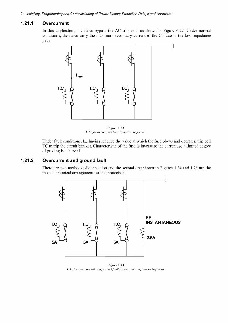
1.21.1 Overcurrent In this application, the fuses bypass the AC trip coils as shown in Figure 6.27. Under normal conditions, the fuses carry the maximum secondary current of the CT due to the low impedance path.
Figure 1.23 CTs for overcurrent use in series trip coils
Under fault conditions, Isec having reached the value at which the fuse blows and operates, trip coil TC to trip the circuit breaker. Characteristic of the fuse is inverse to the current, so a limited degree of grading is achieved.
1.21.2 Overcurrent and ground fault There are two methods of connection and the second one shown in Figures 1.24 and 1.25 are the most economical arrangement for this protection.
Figure 1.24 CTs for overcurrent and ground fault protection using series trip coils

Need for Protection 25
Figure 1.25 Economical use of overcurrent and ground fault configuration

26 Installing, Programming and Commissioning of Power System Protection Relays and Hardware