Embed Size (px)
Citation preview

IAT-300 www.powercommander.com Dual Channel Auto-tune Installation Guide - 1IAT-300 www.powercommander.com Dual Channel Auto-tune Installation Guide - 1
INSTALLATION
The Auto Tune kit is a universal product that can be utilized on any model using the PCV and which has a 12v power source.
Some stock and aftermarket exhausts come equipped with O2 sensor bungs. If your exhaust system already has 18mm x 1.5 threaded bungs, then you can usually use them for the Auto Tune wideband O2 sensors. If you have to drill holes for new bungs (mild steel bungs included), we recommend doing so before the catalytic converter (if applicable). It is recommended to position the weld bungs/sensors approximately 6”-18” from the exhaust port of the cylinder.
Mount the weld bosses in a manner that reduces the risk of moisture contamination on the sensors. Condensation can build up in the exhaust pipes and potentially damage the sensors. Ideally, you should orient the weld bosses so the sensors are between the 9 o’clock and 3 o’clock position. A 10° inclination off the horizontal plane should be considered a minimum.
Note: Verify you have adequate clearance for the sensor and wiring harness. Make sure the O2 sensor harness is as straight as possible. If you must, secure the harness to keep away from danger or heat. Make sure you do not squeeze or pinch the sheathing of the harness near the sensor.
1. Install the Auto Tune module near the PCV.
2. Connect the Auto Tune module to the PCV module using the supplied CAN link cable. It does not matter which expansion ports the cable is connected to.
3. Connect the O2 sensor cables to the O2 sensors and route the cables to the Auto Tune module, ensuring the cables will not get pinched or damaged by the exhaust. The cables can be trimmed shorter, if desired.
4. Connect the O2 sensor cables to the Auto Tune module. Input #1 on the back of the Auto Tune module refers to the vehicle’s front or left cylinder and Cylinder #1 in the PCV software.
5. Connect the BLACK wire from the Auto Tune to a good chassis ground using either one of the supplied posi-taps or ring lug. The negative side of the battery is a good location.
6. Connect the RED wire of the Auto Tune to a switched 12v source using the supplied posi-tap. The power for the tail light is usually a good power source. Most PCV install guides will tell you the wire color for this location. The Auto Tune can pull up to 5 amps while the sensors are warming up.
7. Block or disable the clean air injection system if applicable (see tech tips).
USING AUTO TUNE
The Auto Tune kit, when used in conjunction with the PCV, allows the bike to be automatically tuned to a target air/fuel ratio. To use this feature you must first enable Auto Tune in the PCV.
1. Click Power Commander Tools >Configure >Features Enables and Input Selections.
2. Enable “Auto Tune Switch” if using a hardware switch to toggle Auto Tune on and off.
3. Enable “Auto Tune” to enable the Auto Tune feature.
4. Click Configure to adjust the Auto Tune configuration settings.
Check this box when using a switch.
Enable and configure the Auto Tune feature.

IAT-300 www.powercommander.com Dual Channel Auto-tune Installation Guide - 2IAT-300 www.powercommander.com Dual Channel Auto-tune Installation Guide - 2
Most maps from Dynojet will include a base Target AFR table. These settings are intended to deliver optimal performance while still maintaining decent fuel mileage in the cruise area (for most models).
5. To alter the AFR targets, click on Target AFR in the tree view.
6. Expand each cylinder and/or gear, if necessary, to view the corresponding table. If necessary, type in different values in the cells. Multiple cells can be highlighted by using click/drag with the mouse.
Shows current table being altered
It is recommended to load a base map into the PCV that best corresponds to your bikes current configuration. This will decrease the time in which it takes for the Auto Tune module to achieve its target air/fuel.
If using an “Auto-tune Switch” a switch can be wired into the PCV to be used to toggle between your base map and learning mode. Any SPST (open/close) type switch can be used. When the switch circuit is OPEN the PCV will be running on the base map only. When the switch circuit is CLOSED the PCV will go into learn mode and Auto Tune will start making fuel trim adjustments.
You can toggle between these modes at any time. The values learned for the fuel trims will be saved but not used if you toggle back to the base map.
7. After an Auto-tune riding session, click Get Map and view the Trim table by clicking on the Trim table in the tree view section. This will display exactly where Auto-tune has made changes and how much.
8. Click Map Tools >Auto Tune Tables>Accept All Trims to accept these trims and transfer them into the base Fuel table. This will zero out the trim table(s) and add the trim values to the base map(s).
9. Click Send Map after accepting the trims to load the newly edited file into the connected PCV device.
The PCV is configured to only allow the software to trim +/- 20% until you manually accept the trims. You can alter these limits in the Auto Tune configuration. The more the PCV learns the lower you can make this value. By lowering this value it will work as a safety net so if something should go wrong in the unit or bike it will not cause the bike to run poorly.
How much time after starting the engine the software waits until it starts sampling.
The temperature the engine needs to reach before the software starts sampling (optional wiring needed to function).
The maximum the software will trim per session.
The number of O2 sensors.
IAT-300 www.powercommander.com Dual Channel Auto-tune Installation Guide - 3IAT-300 www.powercommander.com Dual Channel Auto-tune Installation Guide - 3
TECH TIPS
• If you should see abnormally high values in the trim tables (max enrichment or max enleanment) then check the following:
• Intake leaks
• Exhaust leaks - check at all exhaust junctions
• Sensor condition - (see O2 Sensor Test)
• Make sure the clean air system is blocked (if applicable). Also called the PAIR valve, the clean air system draws fresh air out of the air box and dumps it into the exhaust port to help ignite any unburned fuel in the exhaust. This extra air will skew the AFR readings of the Auto Tune module.
• Dynojet does not recommend inputting values in the 0% column of the Target AFR tables. If you should need to tune the 0% column to combat popping on deceleration input values directly in the Fuel tables.
• If fuel mileage is a concern then you can alter the Target AFR values in the cruise range. Dynojet considers the cruise range to be around 5-20% throttle. Dynojet does not recommend making the bike any leaner than 14.7 in the Target AFR cells.
• Dynojet has found that for the best compromise of fuel mileage and throttle response to set the cruise range to 13.7-14.0.
• For all other ranges 12.8-13.4 seems to work best. For the best results it is recommended to bring the bike to an Authorized Tuning Center to have them verify the AFR values.
• Make sure the sensor is not dropped or subjected to wet conditions. The O2 sensors used in this kit are a Bosch unit and do NOT come with any warranty.
• To verify that Auto Tune is working you should see a real time AFR reading in the lower right hand corner of the PC5 software.
• An AFR value of 9.99 could indicate a faulty sensor or the sensor is wired incorrectly to the module. It is normal to see an AFR value of 9.99 for about the first 30 seconds of run time, while the sensor is being heated up.
• An AFR value of 0.00 could indicate a firmware problem, or that Auto Tune has not been enabled in the software, or that Auto-tune configurations are not currently allowing Auto-tune to sample. This could also indicate a problem in the CAN bus, such as a damaged or loose CAN link cable or a missing CAN termination plug. (NOTE: Newer Auto-tune modules with a serial number starting with 15 or higher, do not come with CAN termination plugs supplied and do not require a CAN termination plug.)
• The “Auto-tune Running” light in the PC5 software will illuminate, if and only if the following conditions have been met:
• You are currently running in an RPM/throttle position cell that has a valid Target AFR value specified. This means that if you are currently idling and there is not a valid Target AFR specified in the idle range of the Target AFR table, the light will stay off.
• Your run time and/or engine temperature configurations have been met. This means that if you are requiring run time or engine temp for Auto-tune to be active, you must have been running for the specified period of time, and/or there is an Engine Temperature channel stream enabled and configured and the current engine temperature is above your specified set point.
• The circuit of your Auto-tune Switch (if enabled) is currently closed. This means if the feature is enabled and the switch circuit is open, Auto-tune will not come on.
• You have an AFR signal streaming into the PC5 module from the Auto-tune module that is within 11.5 – 15.0 AFR. You should see an AFR gauge in the main screen of the PC5 software.
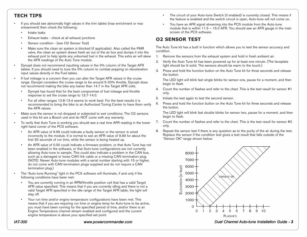
O2 SENSOR TEST
The Auto Tune kit has a built in function which allows you to test the sensor accuracy and condition.
1. Remove the sensors from the exhaust system and hold in fresh ambient air.
2. Verify the Auto Tune kit has been powered up for at least one minute. (The faceplate light should be lit solid. The sensors should be warm to the touch.)
3. Press and hold the function button on the Auto Tune kit for three seconds and release the button.
The LED light will blink fast single blinks for sensor one, pause for a moment, and then begin to flash.
4. Count the number of flashes and refer to the chart. This is the test result for sensor #1 only.
5. Initiate the test again to test the second sensor.
6. Press and hold the function button on the Auto Tune kit for three seconds and release the button.
The LED light will blink fast double blinks for sensor two, pause for a moment, and then begin to flash.
7. Count the number of flashes and refer to the chart. This is the test result for sensor #2 only.
8. Repeat the sensor test if there is any question as to the purity of the air during the test. Replace the sensor if the condition test gives a test result that falls outside of the “Sensor OK” range shown below.