Embed Size (px)
Citation preview
GS SeriesGas Steam Humidifier
Installation,
User & Maintenance
Guide
Form #07-287150-6222
IMPORTANT: Read and save this guide for future reference. Thisguide to be left with equipment owner.
FOR YOUR SAFETY:
Do not store or use gasoline or other flammable vapors and liquids inthe vicinity of this or any other appliance.
WHAT TO DO IF YOU SMELL GAS:
Do not try to light any appliance.Do not touch any electrical switch; do not use any telephone in yourbuilding.Immediately call your gas supplier from a neighbor’s telephone.Follow the gas supplier’s instructions. If you can not reach your gassupplier, call the fire department.
UNIT OPERATING RANGES:
Max. Ambient Temperature 104ºF (40ºC).Min. Ambient Temperature 41ºF (5ºC).Max. Relative Humidity (RH) non-condensing 95% RH.Min. Relative Humidity (RH) non-condensing 5% RH.
WARNING:
Improper installation, adjustment, alteration, service or maintenancecan cause injury or property damage. Refer to this manual. Forassistance or additional information consult a qualified installer, serviceagency, or the gas supplier.
WARNING:
If the information in this manual is not followed exactly, a fire orexplosion may result causing property damage, personal injury or lossof life.
IMPORTANT:
Read and save this guide for future reference. This guide to be left withequipment owner.
Table Of Contents
GENERAL 1
- WARNING . . . . . . . . . . . . . . . . . . . . . . . . . . . . . . . . . . . . . . . . . . . . . . . . 1
- DELIVERY . . . . . . . . . . . . . . . . . . . . . . . . . . . . . . . . . . . . . . . . . . . . . . . . 1
- RECEIVING & UNPACKING EQUIPMENT. . . . . . . . . . . . . . . . . . . . . . . . . . . . . . . . 1
- GENERAL SPECIFICATIONS . . . . . . . . . . . . . . . . . . . . . . . . . . . . . . . . . . . . . . 1
- MODEL DESIGNATION . . . . . . . . . . . . . . . . . . . . . . . . . . . . . . . . . . . . . . . . . 1
MODEL SPECIFICATION 2
GS INDOOR INSTALLATION 3
- LOCATING AND MOUNTING . . . . . . . . . . . . . . . . . . . . . . . . . . . . . . . . . . . . . . 4
- GAS PIPING . . . . . . . . . . . . . . . . . . . . . . . . . . . . . . . . . . . . . . . . . . . . . . . 5
- COMBUSTION AIR REQUIREMENTS . . . . . . . . . . . . . . . . . . . . . . . . . . . . . . . . . . 6
- DIRECT VENT GUIDELINES. . . . . . . . . . . . . . . . . . . . . . . . . . . . . . . . . . . . . . . 6
- EXHAUST VENTING . . . . . . . . . . . . . . . . . . . . . . . . . . . . . . . . . . . . . . . . . . . 7
- ADDITIONAL REQUIREMENTS WHEN VENTING THROUGH A SIDEWALL . . . . . . . . . . . . . 11
- ELECTRICAL . . . . . . . . . . . . . . . . . . . . . . . . . . . . . . . . . . . . . . . . . . . . . . 12
- PRIMARY WIRING . . . . . . . . . . . . . . . . . . . . . . . . . . . . . . . . . . . . . . . . . . . 13
- LOW VOLTAGE CONTROL WIRING . . . . . . . . . . . . . . . . . . . . . . . . . . . . . . . . . 14
- CONTROL INSTALLATION . . . . . . . . . . . . . . . . . . . . . . . . . . . . . . . . . . . . . . . 15
- PLUMBING . . . . . . . . . . . . . . . . . . . . . . . . . . . . . . . . . . . . . . . . . . . . . . . 15
- FILL WATER SUPPLY LINE . . . . . . . . . . . . . . . . . . . . . . . . . . . . . . . . . . . . . . 15
- DRAIN LINE . . . . . . . . . . . . . . . . . . . . . . . . . . . . . . . . . . . . . . . . . . . . . . . 15
- AUX DRAIN PORT . . . . . . . . . . . . . . . . . . . . . . . . . . . . . . . . . . . . . . . . . . . 16
-STEAM LINES AND CONDENSATE LINE . . . . . . . . . . . . . . . . . . . . . . . . . . . . . . . 16
GS OUTDOOR INSTALLATION 16
- MOUNTING . . . . . . . . . . . . . . . . . . . . . . . . . . . . . . . . . . . . . . . . . . . . . . . 16
-TYPICAL GSTC OUTDOOR INSTALLATION . . . . . . . . . . . . . . . . . . . . . . . . . . . . . . 17
- ROOF CURB DIMENSIONS . . . . . . . . . . . . . . . . . . . . . . . . . . . . . . . . . . . . . . 18
- GAS PIPING. . . . . . . . . . . . . . . . . . . . . . . . . . . . . . . . . . . . . . . . . . . . . . . 19
- EXHAUST VENTING . . . . . . . . . . . . . . . . . . . . . . . . . . . . . . . . . . . . . . . . . . 20
- ELECTRICAL INSTALLATION . . . . . . . . . . . . . . . . . . . . . . . . . . . . . . . . . . . . . 20
- FILL WATER SUPPLY LINE . . . . . . . . . . . . . . . . . . . . . . . . . . . . . . . . . . . . . . 21
- DRAIN LINE . . . . . . . . . . . . . . . . . . . . . . . . . . . . . . . . . . . . . . . . . . . . . . . 21
- AUXILIARY DRAIN . . . . . . . . . . . . . . . . . . . . . . . . . . . . . . . . . . . . . . . . . . . 21
- STEAM LINES. . . . . . . . . . . . . . . . . . . . . . . . . . . . . . . . . . . . . . . . . . . . . . 22
PRINCIPLE OF OPERATION 22
- COMBUSTION . . . . . . . . . . . . . . . . . . . . . . . . . . . . . . . . . . . . . . . . . . . . . 22
- WATER MANAGEMENT . . . . . . . . . . . . . . . . . . . . . . . . . . . . . . . . . . . . . . . . 22
- START UP PROCEDURE . . . . . . . . . . . . . . . . . . . . . . . . . . . . . . . . . . . . . . . 23
- FILLING THE SYSTEM . . . . . . . . . . . . . . . . . . . . . . . . . . . . . . . . . . . . . . . . . 23
- TESTING THE IGNITION SAFETY SHUT-OFF. . . . . . . . . . . . . . . . . . . . . . . . . . . . . 23
- STARTING THE HUMIDIFIER . . . . . . . . . . . . . . . . . . . . . . . . . . . . . . . . . . . . . 24
- TAKING OUT OF OPERATION . . . . . . . . . . . . . . . . . . . . . . . . . . . . . . . . . . . . . 24
- INSTALLATION CHECKLIST . . . . . . . . . . . . . . . . . . . . . . . . . . . . . . . . . . . . . . 25
- SCALE MANAGEMENT . . . . . . . . . . . . . . . . . . . . . . . . . . . . . . . . . . . . . . . . . 27
- WATER QUALITY . . . . . . . . . . . . . . . . . . . . . . . . . . . . . . . . . . . . . . . . . . . . 27
- FAULT CONDITIONS . . . . . . . . . . . . . . . . . . . . . . . . . . . . . . . . . . . . . . . . . . 28
MAINTENANCE 28
- DRAINING THE TANK . . . . . . . . . . . . . . . . . . . . . . . . . . . . . . . . . . . . . . . . . 28
- MANDATORY MAINTENANCE SCHEDULE . . . . . . . . . . . . . . . . . . . . . . . . . . . . . . 29
- CLEANING THE TANK . . . . . . . . . . . . . . . . . . . . . . . . . . . . . . . . . . . . . . . . . 30
- SERVICING THE UNIT . . . . . . . . . . . . . . . . . . . . . . . . . . . . . . . . . . . . . . . . . 31
- SERVICE CHECKS . . . . . . . . . . . . . . . . . . . . . . . . . . . . . . . . . . . . . . . . . . . 31
- COMPONENTS REPLACEMENT. . . . . . . . . . . . . . . . . . . . . . . . . . . . . . . . . . . . 32
-Hot Surface Igniter and Flame Sensor Replacement . . . . . . . . . . . . . . . . . . . . . . . . 32
-Burner Removal and Installation . . . . . . . . . . . . . . . . . . . . . . . . . . . . . . . . . . . 32
-Removal and Installation of the Combustion Blower. . . . . . . . . . . . . . . . . . . . . . . . . 33
-Gas Valve Replacement . . . . . . . . . . . . . . . . . . . . . . . . . . . . . . . . . . . . . . . 33
-Air Switch Replacement . . . . . . . . . . . . . . . . . . . . . . . . . . . . . . . . . . . . . . . 34
-Float Chamber Replacement . . . . . . . . . . . . . . . . . . . . . . . . . . . . . . . . . . . . 34
-Transformer Replacement . . . . . . . . . . . . . . . . . . . . . . . . . . . . . . . . . . . . . . 35
-Fill Valve Replacement . . . . . . . . . . . . . . . . . . . . . . . . . . . . . . . . . . . . . . . 35
-Drain Pump Replacement . . . . . . . . . . . . . . . . . . . . . . . . . . . . . . . . . . . . . . 36
-Fill Box Replacement . . . . . . . . . . . . . . . . . . . . . . . . . . . . . . . . . . . . . . . . 36
-Removal of the Heat Exchanger . . . . . . . . . . . . . . . . . . . . . . . . . . . . . . . . . . . 37
- DIP SWITCH SETTINGS . . . . . . . . . . . . . . . . . . . . . . . . . . . . . . . . . . . . . . . . 38
- SOFTWARE FLOW CHART . . . . . . . . . . . . . . . . . . . . . . . . . . . . . . . . . . . . . . 39
- FAULT AND WARNING LIST . . . . . . . . . . . . . . . . . . . . . . . . . . . . . . . . . . . . . . 60
- EXPLODED VIEW INTERNAL COMPONENTS SPARE PARTS . . . . . . . . . . . . . . . . . . . . 63
- EXPLODED VIEW INDOOR CABINETRY SPARE PARTS. . . . . . . . . . . . . . . . . . . . . . . 65
- EXPLODED VIEW OUTDOOR CABINETRY SPARE PARTS . . . . . . . . . . . . . . . . . . . . . 67
- GS QUICK REFERENCE . . . . . . . . . . . . . . . . . . . . . . . . . . . . . . . . . . . . . . . . 71
GENERALThis installation guide has been designed to
provide assistance when installing, mounting, andcommissioning a GS Series humidifier. Actual on siteapplication may vary. Consult Technical Services oryour local NORTEC representative.
WARNING
� Improper installation, adjustment, alteration,service, maintenance, or use can cause carbonmonoxide poisoning, an explosion, fire, electricalshock, or other conditions which may causepersonal injury or property damage. Consult aqualified installer, service agency, local gassupplier, or your distributor or branch forinformation or assistance. The qualified installeror agency must use only factory authorized andlisted kits or accessories when modifying thisproduct. A failure to follow this warning cancause electrical shock, fire, personal injury, ordeath.
� Should overheating occur, or the gas fail to shutoff, shut off the manual gas valve to the appliancebefore shutting off the electrical supply.
� Do not use this appliance if any part has beenunder water. Immediately call a qualified servicetechnician to inspect the appliance and to replaceany part of the control system and any gascontrol which has been under water.
DELIVERY
The standard delivery includes:
� Gas Steam humidifier equipped with desiredoptions.
� In a bag you will find:
- Manuals.
- Adapter fittings for water connection.
- Steamhose for steam outlet with clamps.
- Hose and clamps for drain connection.
� The GS Indoor Series offers an optionaltelescopic stand mounted inside the unit legs.Stand cross bracing are shipped with the unit.
� The GS Outdoor Series comes with all requiredventing to be installed on site.
� Desired accessories ordered.
RECEIVING & UNPACKING EQUIPMENT
� Check packing slip to ensure ALL material hasbeen delivered.
� All material shortages are to be reported toNORTEC within 48 hours from receipt of goods.NORTEC assumes no responsibility for anymaterial shortages beyond this period.
� Inspect shipping boxes for damage and note onshipping waybill accordingly.
� After unpacking, inspect equipment for damageand if damage is found, notify the shipperpromptly.
� All NORTEC products are shipped on an F.O.B.factory basis. Any and all damage, breakage orloss claims are to be made directly to theshipping company.
GENERAL SPECIFICATIONS
The NORTEC GS Series humidifier is acompletely new patented design based on leadingedge technology. The GS is designed to provide cleansteam humidification at an economical price.
The GS Series humidifiers are designedexclusively for humidification in ventilation systems ordirect room humidification. Any other type ofapplication, without the written consent of Nortec oryour Nortec agent, is considered as not conformingwith the intended purposes. The manufacturer/supplier can not be made liable for any damagesresulting from improper use.
- 1 -
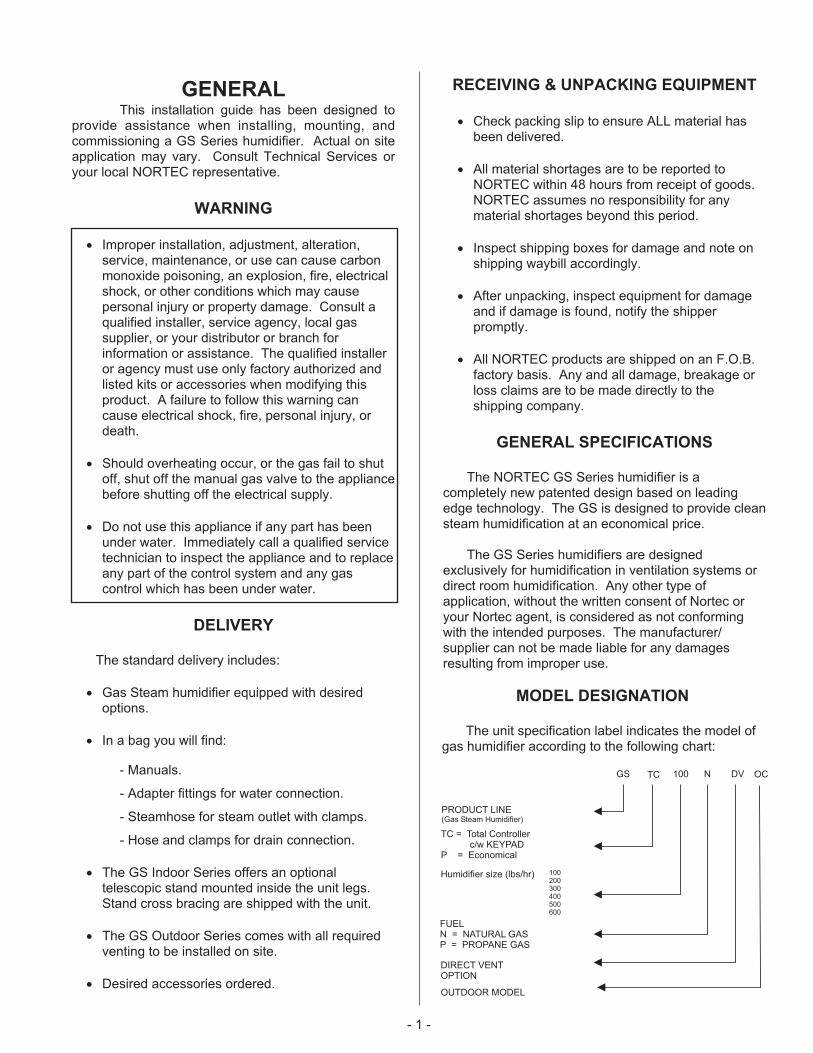
MODEL DESIGNATION
The unit specification label indicates the model ofgas humidifier according to the following chart:
GS 100 N DV
PRODUCT LINE(Gas Steam Humidifier)
Humidifier size (lbs/hr)
FUELN = NATURAL GASP = PROPANE GAS
DIRECT VENTOPTION
TC = Total Controllerc/w KEYPAD
P = Economical
TC
100200300400500600
OC
OUTDOOR MODEL
- 2 -
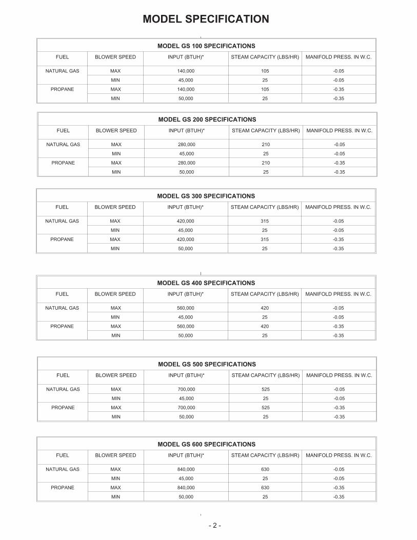
MODEL GS 100 SPECIFICATIONS
FUEL BLOWER SPEED INPUT (BTUH)* STEAM CAPACITY (LBS/HR) MANIFOLD PRESS. IN W.C.
NATURAL GAS MAX 140,000 105 -0.05
MIN 45,000 25 -0.05
PROPANE MAX 140,000 105 -0.35
MIN 50,000 25 -0.35
MODEL GS 200 SPECIFICATIONS
FUEL BLOWER SPEED INPUT (BTUH)* STEAM CAPACITY (LBS/HR) MANIFOLD PRESS. IN W.C.
NATURAL GAS MAX 280,000 210 -0.05
MIN 45,000 25 -0.05
PROPANE MAX 280,000 210 -0.35
MIN 50,000 25 -0.35
MODEL GS 300 SPECIFICATIONS
FUEL BLOWER SPEED INPUT (BTUH)* STEAM CAPACITY (LBS/HR) MANIFOLD PRESS. IN W.C.
NATURAL GAS MAX 420,000 315 -0.05
MIN 45,000 25 -0.05
PROPANE MAX 420,000 315 -0.35
MIN 50,000 25 -0.35
MODEL GS 400 SPECIFICATIONS
FUEL BLOWER SPEED INPUT (BTUH)* STEAM CAPACITY (LBS/HR) MANIFOLD PRESS. IN W.C.
NATURAL GAS MAX 560,000 420 -0.05
MIN 45,000 25 -0.05
PROPANE MAX 560,000 420 -0.35
MIN 50,000 25 -0.35
MODEL GS 500 SPECIFICATIONS
FUEL BLOWER SPEED INPUT (BTUH)* STEAM CAPACITY (LBS/HR) MANIFOLD PRESS. IN W.C.
NATURAL GAS MAX 700,000 525 -0.05
MIN 45,000 25 -0.05
PROPANE MAX 700,000 525 -0.35
MIN 50,000 25 -0.35
MODEL GS 600 SPECIFICATIONS
FUEL BLOWER SPEED INPUT (BTUH)* STEAM CAPACITY (LBS/HR) MANIFOLD PRESS. IN W.C.
NATURAL GAS MAX 840,000 630 -0.05
MIN 45,000 25 -0.05
PROPANE MAX 840,000 630 -0.35
MIN 50,000 25 -0.35
MODEL SPECIFICATION

- 3 -
Snap on Installation
Steamline
Steam Outlet
B or BH Venting Type
Control Wiring
Main Power Disconnect
Shut Off
To Drain
Auxiliary Drain
Air Gap with Funnel
Service Access Door(Mechanical)
Service AccessDoor (Electrical)
Clean OutAccess Door
Optional Stand
Drain
Gas LineConnection
Fresh WaterFill Line3/4"min 30-80 psi
Exhaust Outlet
OptionalDirect Vent
Figure #1Typical Installation (Indoor)
HIGH ALTITUDE - A derate in input exists for installations at higher altitudes. For Canadian models, an automatic10% derate applies to installations from 2000-4500 feet. For U.S. Models, refer to the chart below for high altitudederate information.
FOR U.S. MODELS ONLY
Altitude Derate %
Feet Meters
0-2000 0-610 0
2001-3000 610-915 8
3001-4000 915-1220 12
4001-4500 1220-1370 16
4501-higher 1370-higher Contact Factory

INDOOR INSTALLATION
The installation must conform with local buildingcodes or, in the absence of local codes, with the ANSIZ223.1, National Fuel Gas Code, and/or CAN/CGAB149 Installation Codes. Refer to the Gas Pipingsection of this manual.
LOCATING AND MOUNTING
GS Series humidifiers are designed for floormounting or on a GS Stand (optional). The clearancedimensions shown in this manual are for referenceonly and are the minimum required for maintenance ofthe humidifier. Local and National Codes should beconsulted prior to final location and installation of thehumidifier. NORTEC cannot accept responsibility forinstallation code violations.
Figure #1 shows a typical installation with allrequired connections to the GS Humidifier. Carefulconsideration should be given to all of theseconnections when choosing a location for thehumidifier.
WARNING: During installation cover thehumidifier to prevent any dust or othercontaminants from entering the cabinets whenactivities such as drilling are taking place.
� Ambient temperature location for humidifier:41ºF - 104ºF (5ºC - 40ºC).
� Relative humidity location for humidifiers:5% rh - 80% rh.
� All GS humidifiers are rated for the clearance toshown in Figure #2.
� Location of the steam distributor should beminimum of 36” above the humidifier.
� DO NOT locate humidifier any further thanabsolutely necessary from steam distributorlocation. Net output will be reduced as a result ofheat loss through steam line. Also, increasedstatic pressure (over 12" W.C.) will result in hotwater going down the drain. Consult factory if thissituation occurs.
� Where possible, mount humidifier at a heightconvenient for servicing.
� Make sure the humidifier is mounted level.
� DO NOT mount humidifier on hot surfaces.
� The humidifier must be installed so that allelectrical components are protected fromexposure to water.
- 4 -
Optional Stand
Minimum36" (91.5 cm)
Right30" (76.2 cm)
Minimum4" (10.2 cm) to vent pipe
Left36" (91.5 cm)
Required only forGSTC/GSP
500/600
Front30" (76.2 cm)
Front ClearanceSide Clearance
Figure #2
Clearance Requirements
� DO NOT mount humidifiers in an area wherefreezing may occur.
� If humidifiers are mounted on a roof, a properlyventilated, temperature controlled, (abovefreezing), weatherproof enclosure must be used.
� DO NOT mount humidifiers on vibrating surface.Consult factory.
� The humidifier shall not be installed directly oncarpeting, tile or other combustible material otherthan wood flooring.
� Some insulating materials may be combustible.Prior to installing this appliance examine the areafor insulating material. If this appliance isinstalled in an insulated space, it must be keptfree and clear of insulating materials. If insulationis added after the appliance is installed, it will benecessary to examine the area again.
GAS PIPING
Installation of piping must be in accordance withlocal codes, and ANSI Z233.1, “National Fuel GasCode,” in the United States or CAN/CGA-B149Installation Codes in Canada.
The following table indicates the maximum andminimum allowable gas pressures for the GasHumidifier.
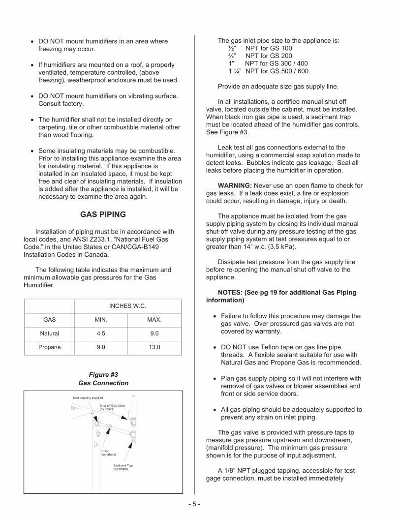
The gas inlet pipe size to the appliance is:½” NPT for GS 100¾” NPT for GS 2001” NPT for GS 300 / 4001 ¼” NPT for GS 500 / 600
Provide an adequate size gas supply line.
In all installations, a certified manual shut offvalve, located outside the cabinet, must be installed.When black iron gas pipe is used, a sediment trapmust be located ahead of the humidifier gas controls.See Figure #3.
Leak test all gas connections external to thehumidifier, using a commercial soap solution made todetect leaks. Bubbles indicate gas leakage. Seal allleaks before placing the humidifier in operation.
WARNING: Never use an open flame to check forgas leaks. If a leak does exist, a fire or explosioncould occur, resulting in damage, injury or death.
The appliance must be isolated from the gassupply piping system by closing its individual manualshut-off valve during any pressure testing of the gassupply piping system at test pressures equal to orgreater than 14” w.c. (3.5 kPa).
Dissipate test pressure from the gas supply linebefore re-opening the manual shut off valve to theappliance.
NOTES: (See pg 19 for additional Gas Piping
information)
� Failure to follow this procedure may damage thegas valve. Over pressured gas valves are notcovered by warranty.
� DO NOT use Teflon tape on gas line pipethreads. A flexible sealant suitable for use withNatural Gas and Propane Gas is recommended.
� Plan gas supply piping so it will not interfere withremoval of gas valves or blower assemblies andfront or side service doors.
� All gas piping should be adequately supported toprevent any strain on inlet piping.
The gas valve is provided with pressure taps tomeasure gas pressure upstream and downstream,(manifold pressure). The minimum gas pressureshown is for the purpose of input adjustment.
A 1/8" NPT plugged tapping, accessible for testgage connection, must be installed immediately
- 5 -
INCHES W.C.
GAS MIN. MAX.
Natural 4.5 9.0
Propane 9.0 13.0
Shut-off Gas Valve(by others)
Sediment Trap(by others)
Inlet coupling supplied
Union(by others)
Figure #3
Gas Connection
upstream of the gas supply connection to theappliance.
COMBUSTION AIR REQUIREMENTS
Provide for adequate combustion and ventilationair in accordance with Sections 8.3, Air for Combustionand Ventilation, of the National Fuel Gas Code, ANSIZ223.1, or Sections 7.2, 7.3, 7.4 of CAN/CGA B149Installation Codes, or applicable provisions of the localbuilding codes.
The required free area of supply air opening is:13 in. sq. (8,387 mm
2), for GS 100
23 in. sq. (14,839 mm2), for GS 200
35 in. Sq. (22,581 mm2), for GS 300
47 in. Sq. (30,323 mm2), for GS 400
59 in. Sq. (38,064 mm2), for GS 500
71 in. Sq. ( 45,806 mm2), for GS 600
Cabinet top and bottom contain air openings toprovide combustion air to the forced draft blower. DONOT BLOCK THESE OPENINGS.
Excessive exposure to contaminated combustionair will result in safety and performance relatedproblems. Known contaminates include halogens,ammonia, and chlorides, excessive dust, lime or dirt.Excessive exposure of electronics to the contaminantswill also result in performance related problems.Contact NORTEC Technical Services if you have anyquestions. If contaminants exist, isolate the unit fromthe contaminated space.
DIRECT VENT GUIDELINES
Installation of the combustion air supply line mustbe carried out by adequately qualified personnel. Alllocal regulations relating to the provision of air supplysystems must be observed and adhered to.
The maximum pipe length for the air supply lineand exhaust is equivalent to 70’ (21m). The vent pipediameter must be maintained over the overall length ofthe vent.
All air piping must be listed type for direct ventapplication with sealed joints and seams, such as Zflex.
The air supply line should be approximately aslong as the flue gas venting and must be supported atevery 5 ft. (1.5 m) and additionally at every pipe bend.
The air supply line must be installed with airsupply terminals provided.
At low temperatures, water condensation can formon the outside of the pipe. To prevent this, it is
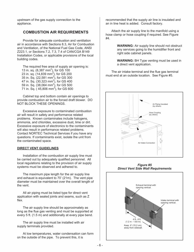
recommended that the supply air line is insulated andan in line heat is added. Consult factory.
Attach the air supply line to the manifold using ahose clamp or hose coupling if required. See Figure#4.
WARNING: Air supply line should not obstructany services going to the humidifier front andright side cabinet panels.
WARNING: BH Type venting must be used ina direct vent application.
The air intake terminal and the flue gas terminalmust end at an outside location. See Figure #5.
- 6 -
Air Piping Insulated(by others)
Hose Coupling(by others)
Air Intake Connection
4 ft - 6 ft(1.2 m - 1.83 m)
Exhaust terminal withopening vertical.
Intake terminal withopening vertical.
Keep 6“ (15.2 cm)away from sidewall.
Figure #5Direct Vent Side Wall Requirements

Location of air intake and flue gas terminal mustcomply with all local and national regulations.
EXHAUST VENTING
The GSTC and GSP are classed category I and IIIfan assisted gas appliances. This allows two methodsof venting. Listed below are instructions for bothventing systems, followed by specific requirements foreach system.
Review the requirements for both category I and IIIinstallations and select the venting method best suitedfor the installation.
Category III class must be used in direct ventapplications.
GENERAL REQUIREMENTS
� The vent systems shall be listed to UL or UL/CSAstandard and meet the installation requirementsof the National Fuel code in the USA ( ANSIZ223.1) and the Canadian StandardsCAN/CGA.B149 Installation Codes. Any localjurisdictions reflecting changes to the abovecodes should be observed.
� In applying the codes, reference should be givento the venting manufactures instructions, theserving gas supplier regulations, and the specificinstructions provided in this manual.
� This appliance must be installed to comply withnational regulations and codes. A qualifiedtechnician, competent with these codes and thelocal requirements of the jurisdiction must carryout the installation.
� Proper removal of combustion gases must beassured, and building materials must beprotected from degradation by flue gases.
� Never mix venting types. (B to BH or visa versa.)Never use two different manufacturer’sequipment for the same chimney.
� All vent runs should be as direct as possible withno more than 6 elbows in the system.
� Maintain an upward slope of ¼” per ft on allhorizontal vent pipe runs.
� This gas humidifier may not be used inconjunction with a power venter or draft inducer.
- 7 -
Trap
Wall
BH type vent using double wall vent
with all joints being air and water tight.
Reference local and/or national codes
before installation of the vent
Condensate tee and trap must
be installed. Take the condensate
to a floor drain or a condensate pump
Hangers straps
Exhaust venting must
be min.4 ft, max.6 ft
in distance apart from
the fresh air intake
for direct venting
BH type double wall with double
wall connectors required.
Note: These are guidelines only. Follow the local and/or national codes in your respective area.
Terminations
supplied with
unit
Direct vent
Inlet
Exhaust venting outlet
Steam
Outlet
CondensateTee 2 ft Min
3” Min
Figure #6Horizontal Venting Using a Direct Vent Application Using BH Type Only
- 8 -
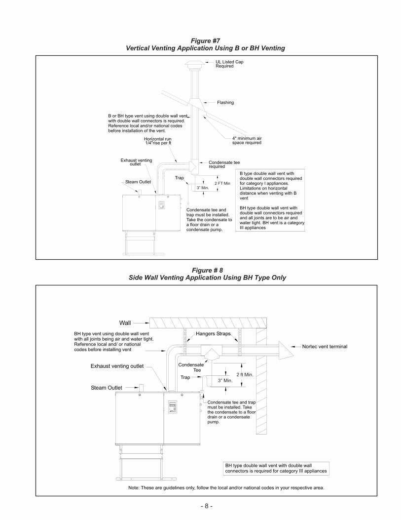
Trap
UL Listed CapRequired
Condensate tee andtrap must be installed.Take the condensate toa floor drain or acondensate pump.
B type double wall vent withdouble wall connectors requiredfor category I appliances.Limitations on horizontaldistance when venting with Bvent
BH type double wall vent withdouble wall connectors requiredand all joints are to be air andwater tight. BH vent is a categoryIII appliances
Flashing
4" minimum airspace required
B or BH type vent using double wall ventwith double wall connectors is required.Reference local and/or national codesbefore installation of the vent.
Condensate teerequired
Steam Outlet
Exhaust ventingoutlet
Horizontal run1/4"rise per ft
2 FT Min3” Min.
Wall
Hangers Straps
CondensateTee
Condensate tee and trapmust be installed. Takethe condensate to a floordrain or a condensatepump.
BH type vent using double wall ventwith all joints being air and water tight.Reference local and/ or nationalcodes before installing vent
Trap
BH type double wall vent with double wallconnectors is required for category III appliances
Note: These are guidelines only, follow the local and/or national codes in your respective area.
Steam Outlet
Exhaust venting outlet
Nortec vent terminal
2 ft Min.
3” Min.
Figure #7Vertical Venting Application Using B or BH Venting
Figure # 8Side Wall Venting Application Using BH Type Only

� For any vent lengths over 20 feet long, insulatethe vent pipe to reduce the amount of condensatethat could form in the flue gases.
� When the venting passes through a cold area, orlocation that has large amounts of air passingover the venting, it should be insulated to preventcondensation from forming inside the venting.
� Vent pipe passing through walls, floors, andceilings, must be installed with the properclearances from combustible materials, andventing manufactures fire stop equipment.
� The venting shall not pass through any circulationair duct or plenum.
WARNING: Provide a screen or barrier to preventpersonal injury in areas where personnel may comeinto contact with hot vent pipes.
� A drip “T” or flue box condensate port should beused for condensate removal. When acondensate drain is used it will be necessary toinstall a trap to prevent flue gases from escaping.
Install a trap with a minimum 12” standingwater column.
� Prior to activating the appliance, ensure that thetrap is filled with water and that the drainterminates in accordance with local plumbingcodes.
� Never vent into a unlined masonry or concretechimney.
� Chimney or vent should extend at least 3’ (1 m)above a roof and at least 2’ (.6 m) above anyridge within 10’ (3 m) of the chimney. Local codesapply.
� Install venting so as to prevent accumulation ofcondensate and have a means for condensateremoval.
� Plastic, PVC, CPVC and HTPV special gas ventsare not approved for use with this appliance.
� The vent must terminate at a sufficient heightabove the roof to prevent blockage by expectedsnowfall.
-9 -
UL Listed CapRequired
Category I gas appliance usesB type venting. Follow localand/or national codes forventing installation.
B type double wall ventwith double wallconnectors is required forcategory I, serving two ormore gas appliances.
Condensate tee and trapmust be installed. Takethe condensate to a floordrain or a condensate pump.
Steam Outlet
Exhaust ventingoutlet
Note: These are guidelines only. Follow local and/ or national codes in your respective area.
CondensateTee
Trap
Figure # 9Co-venting Application Using B Vent Only
� Vent pipe must be secured with hangers or pipestraps
� All horizontal runs must be adequately supportedwith hangers or straps to prevent sagging.
Installation as a Category I Appliance
� The GS series humidifiers have a fan-assistedcombustion which operates with a non-positivevent static pressure when installed with theappropriate vent diameter.
� Category I appliances must be vented verticallyor nearly vertical. (See Figure #7 & #9)
� This category appliance is restricted to verticalventing installations with limits placed onhorizontal lengths and vent diameters. Refer tothe tables in local and/or national codes. Nosidewall termination is accepted.
� Vent piping must be UL or UL/CSA listed type Bor B-W.
Recommended B-Venting Manufacturers
1. Simpson Dura-Vent
2. Selkirk Canada Corporation
3. American Metal Products
4. Metal-Fab Inc.
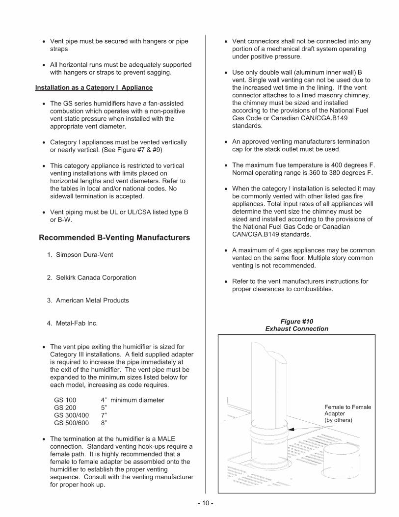
� The vent pipe exiting the humidifier is sized forCategory III installations. A field supplied adapteris required to increase the pipe immediately atthe exit of the humidifier. The vent pipe must beexpanded to the minimum sizes listed below foreach model, increasing as code requires.
GS 100 4” minimum diameterGS 200 5”GS 300/400 7”GS 500/600 8”
� The termination at the humidifier is a MALEconnection. Standard venting hook-ups require afemale path. It is highly recommended that afemale to female adapter be assembled onto thehumidifier to establish the proper ventingsequence. Consult with the venting manufacturerfor proper hook up.
� Vent connectors shall not be connected into anyportion of a mechanical draft system operatingunder positive pressure.
� Use only double wall (aluminum inner wall) Bvent. Single wall venting can not be used due tothe increased wet time in the lining. If the ventconnector attaches to a lined masonry chimney,the chimney must be sized and installedaccording to the provisions of the National FuelGas Code or Canadian CAN/CGA.B149standards.
� An approved venting manufacturers terminationcap for the stack outlet must be used.
� The maximum flue temperature is 400 degrees F.Normal operating range is 360 to 380 degrees F.
� When the category I installation is selected it maybe commonly vented with other listed gas fireappliances. Total input rates of all appliances willdetermine the vent size the chimney must besized and installed according to the provisions ofthe National Fuel Gas Code or CanadianCAN/CGA.B149 standards.
� A maximum of 4 gas appliances may be commonvented on the same floor. Multiple story commonventing is not recommended.
� Refer to the vent manufacturers instructions forproper clearances to combustibles.
- 10 -
Female to FemaleAdapter(by others)
Figure #10Exhaust Connection
� This appliance should not be connected to achimney flue servicing a separate appliancedesigned to burn solid fuel. Never connect thishumidifier to a chimney servicing a fireplace.
� This venting category cannot be used in directvent applications.
Installation as a Category III Appliance
� This venting system can be installed horizontallyor vertically and can terminate on a rooftop orsidewall provided the NFGC (Nation Fuel GasCode) and CAN/CGA- B149 codes are followed.The venting manufacturer instructions must alsobe followed. See Figure # 6,#7 & #8.
� This venting must be used in all direct ventapplications.
� This category installation may not be commonvented with any other natural draft gas applianceor power assist appliance. The humidifier cannotshare a chimney flue servicing an appliancedesigned to burn solid fuel.
� Venting must be UL or UL/CSA listed, tested toULC-5636 Standard. Venting may be BH or Lvent. Special gas vent shall be listed and installedin accordance with the terms of the special gasvent listing and the manufacture’s instructions.The special instructions listed below should befollowed as well.
� All joints must be sealed using high temperatureRTV silicone.
BH Vent Manufacturers
1. Flex-L International
2. Fas-N Seal
3. Heat-Fab Inc.
4. Z Flex
� The gas humidifier is supplied with the followingexhaust outlets.
GS 100 3”GS 200 4”GS 300/400 5”GS 500/600 6”
� The venting must remain the same diameterthroughout the installation.
WARNING: Provide a screen or barrier to preventpersonal injury in areas where inadvertent personnelcontact with vent pipe can occur.
� A minimum equivalent vent length of 7 feet mustbe connected to the humidifier. Vent lengthsmust not exceed 100’ (30 m). Each 90° elbowis equivalent to 10’ and each 45° elbow equals 5'.The vent run should be as direct as possible withno more than 6 elbows in the system.
� Diret vent applications, length of vent should notexceed 70” in equivalent length.
ADDITIONAL REQUIREMENTS WHEN VENTING
THROUGH A SIDEWALL
For sidewall venting, locate the humidifier as closeas possible to the wall being used.
Locate the vent terminal at least three feet aboveany forced air inlet located within ten feet; or at leastfour feet below, four feet horizontally from, or one footabove any door, window, or gravity air inlet into anybuilding.
A minimum horizontal clearance of four feet fromelectric meters, gas meters, regulator and reliefequipment is required.
For sidewall vent terminations, the humidifier mustbe installed with the certified vent terminal that can bepurchased from Nortec.
GS 100 3” Nortec P/N 1502321
GS 200 4” Nortec P/N 1502322
GS 300/400 5” Nortec P/N 1507320
GS 500/600 6” Nortec P/N 1507321
Locate the vent terminal at least seven feet abovegrade when it is adjacent to public walkways.
Locate the bottom of the vent terminal at leasttwelve inches above grade or ground, or normallyexpected snow accumulation level. The snow levelmay be higher on walls exposed to prevailing winds.
Avoid areas where local experience indicates thatcondensate drip may cause problems such as aboveplanters, patios, or over public walkways, or over anarea where condensate or vapor could create anuisance or hazard, or could be detrimental to theoperation of regulators, relief valves, or otherequipment. Refer to the vent manufacturer'sinstallation instructions.
- 11 -

The vent terminal must be installed in the sameatmospheric pressure zone as the combustion air inletof the humidifier. If this is not possible (as in cases ofpositive or negative room pressures) the humidifiershould be installed with the direct vent option.
ELECTRICAL
PRIMARY WIRING
All work concerning the electrical installationmust be performed by qualified personnel.
WARNING: The electrical parts inside thehumidifier are very sensitive to electrostatic discharge.Appropriate measures against electrostatic discharge(ESD protection) must be taken when carrying outinstallation work.
� The humidifier should only be connected toprimary power (mains power) after all installationwork has been completed.
� An external disconnect switch must be installedclose to the unit to allow for power interruptionduring servicing and/or maintenance.
� Humidifiers require field wiring to primary voltageterminal blocks. Power requirement must be120V or 208-240 Vac, 15A separately fusedcircuit, single phase. Use only copper wire with aminimum 70 �C (158 �F) temperature rating.Wiring can be fed through a 7/8" hole on thebottom or the top of the control compartment.See Figure #1.
� When installed, the appliance must be electricallygrounded in accordance with local codes or, inthe absence of local codes, with the NationalElectrical Code, ANSI/NFPA 70, and/or the CSAC22.1 Electrical Code, if an external electricalsource is utilized.
� External wiring sizes must be in accordance withNEC and/or CEC and existing local electricalcodes and by-laws.
LOW VOLTAGE CONTROL WIRING
All GS models require at least one type of inputcontrol signal for unit operation. Refer to the sectionsbelow that detail the types of controls that can be usedwith each model.
Low voltage control terminal strips are provided inthe electrical compartment. Internal sides are factorywired. External sides are to be field wired. Refer tothe specific control-wiring diagram supplied with eachunit.
Field wiring from humidistat to humidifier andbetween devices should be shielded 18 AWG orheavier and kept as short as possible.
Controls are available from NORTEC asaccessories and can be ordered with the humidifier.Controls by others may also be used as long as theymeet the criteria noted below. The following is asummary of the common types of controls that may beused with NORTEC Gas Humidifiers.
Wall or Duct Mounted Control On/Off
Humidistat: Wired to make on drop in humidity,
break on rise to setpoint. Set to desired RH. Can
be a make/break set of contacts from a Building
Automation System.
Duct Mounted Safety High Limit On/Off
Humidistat: Wired to make on drop in humidity,
break on rise to safety setpoint. Set to
approximately 85% RH as a safety to prevent
saturation and wetting in the duct. Highly
recommended for ducted applications.
Duct Mounted Safety Air Proving On/Off Switch:Wired to make when sensing air flow, break when noair flow. Used as a safety to prevent saturation whenthere is no air flow. Highly recommended for ductedapplications.
Wall or Duct Mounted Modulating Humidistat:Provides a modulating signal to the unit thatrepresents the output (up to 100%) required from thehumidifier. Signal type can be changed in the field viadip switch settings on the logic control board.
All GS models may be configured for either singleor dual channel modulation. Control signals can be0-10 VDC or 0-20 mA (0-5 VDC, 1-5 VDC, 4-20 mAand 2-10 VDC are also available). The unit must beordered from the factory for the desired signal typeand number of channels. When configured for2-channel modulation the humidifier will generatesteam only if both channels indicate a demand. If bothchannels are demanding steam the humidifier willsatisfy the lower demand signal.
- 12 -

- 13 -
L1
L2
Ground
Ground Wire Ground
Leg
2 Pole
Terminal
Block
DedicatedCircuit
BreakerOr
DisconnectNote:- 600V/3 Phase Supply.
Ground
Ground Wire Ground
Leg
2 Pole
Terminal
Block
L3
Neutral
L1
L2
Ground
Ground Wire Ground
Leg
2 Pole
Terminal
Block
L3
Neutral
L1
GroundGround Wire
Ground Leg
3 Pole
Terminal
Block
Neutral
PRIMARY208-240V1phase linevoltagewiring tounitVOLTAGE
(ACTUAL)
E
X
T
I
N
T
E
X
T
I
N
T
E
X
T
I
N
T
E
X
T
I
N
T
DedicatedCircuit
BreakerOr
Disconnect
DedicatedCircuit
BreakerOr
Disconnect
DedicatedCircuit
BreakerOr
Disconnect
(BYOTHERS)
600V/3ph
460V/3ph
208V/3ph
380V/3ph
StepdownTransformer600V/208Vbyothers
StepdownTransformer460V/208Vbyothers
L1
L2
Neutral
L2
L3
L3
- 600V/1phbetweenany twohot leg.- 347V/1phbetweenhotandneutral.
Note:- 460V/3 Phase Supply.
- 460V/1phbetweenany twohot leg.- 277V/1phbetweenhotandneutral.
Note:- 380V/3 Phase Supply.- 380V/1phasebetween twohot legs.- 220V/1phasebetweenhotandneutral.
Note:- 208V/3 Phase Supply.- 208V/1phasebetween twohot legs.- 120V/1phasebetweenhotandneutral.
L1
GroundGround Wire
Ground Leg
3 Pole
Terminal
Block
Note:- 120V/1phaseSupply.- 120V/1phasebetweenhotandneutral.- 240V/1phasebetween two120V/1phsupply.
Neutral
E
X
T
I
N
T
DedicatedCircuit
BreakerOr
Disconnect
120V/1phL2
120V/1ph
NOTE: VoltageAtTerminalBlockMustBe InAccordanceWithSpec.Label.AllWiringToBe InAccordanceWithExistingNationalAndLocalElectricalCodes.
L1
GroundGround Wire
Ground Leg
Note:- 120V/1phaseSupply.
- 120V/1phasebetweenhotandneutral.- 240V/1phasebetween two120V/1phsupply.
Neutral
E
X
T
I
N
T
120V/1ph L1Neutral
2 Pole
Terminal
Block
PRIMARY120V1phase linevoltagewiring tounit

- 14 -
WARNING: Fai lure to wi re the contro l ler in accordance wi th the wir ing diagram that was suppl iedwi th the uni t could permanent ly damage the GSTC/GSP board. Such errors wi l l vo id the uni t warranty.
GS SERIESEXTERNAL CONTROLS WIRING CONNECTIONS
LOW VOLTAGE TERMINAL STRIP
NOTE: This is a wiring diagram only. For specific wiring instructions, it is necessary to referto the wiring diagram which is supplied with each unit.
generic
1 2 3 4 65 7 8 9 10 1211EXTERNAL
INTERNAL
EXTERNAL
INTERNAL
Security Loop
Mo
du
latio
nIn
pu
tS
ign
al“A
"
Mo
du
latio
nIn
pu
tS
ign
al“B
”
10
Vd
co
utp
ut
Fu
llTa
nk
Blo
wD
ow
n(F
TB
D)
en
ab
le(2
4V
ac)
Sa
fety
Inte
rru
pt
(24
Va
c)
NOTE: If no On/Off Control is used then a field jumpermust be connected across terminals 1 and 2 in orderfor the humidifier to operate.
14 1815 16 1713
CO
M
CO
M
CO
M
CO
M
N.O
.
N.O
.
N.O
.
N.O
.
N.C
.
Hum
idifie
r“O
N”
Hum
idifie
r“A
CT
IVE
”
Hum
idifie
r“S
ER
VIC
E”
Hum
idifie
r“F
AU
LT
”Low Voltage Terminal Strip
1 & 2: Wire all on/off controls and safeties between these two terminals. If not used, jumper 1 & 2 for theunit to operate.
4: Modulating input to humidifier “A”.
5: Modulating input to humidifier “B”.
6: 10 Vdc output.
8: When 24 Vac input received, the unit will initialize a full tank blowdown.
9: Safety interrupt (24 Vac).
10 & 11: Remote indication connection for humidifier “on” status indication.
12 & 13: Remote indication connection for humidifier “active” status.
14 & 15: Remote indication connection for service required indication.
16 & 17 & 18: Remote indication connection for fault indication.
+ +
CONTROL INSTALLATION
� Mount any wall humidistat (control or high limit)over standard electrical box at height similar totypical thermostat. Any wall humidistat should bein location representative of overall space beinghumidified and not in path of blower pack or airsupply grille. Do not mount on an outside wallwhere temperature fluctuations can affect controlresponse.
� Mount duct humidistat in location representativeof overall air humidity, usually in return duct. Donot mount it directly in front of steam distributor orin turbulent or mixing zone. Mount humidistatwhere air's humidity and temperature are uniformand representative of spaces being humidified.
� Mount duct high limit humidistat downstream ofsteam distributors far enough that, under normalhumidity and air flow conditions, steam will havebeen fully absorbed (typically at least 10 feet). Itmust be located to sense high humidity onlywhen uniform and representative air isover-humidified or approaching saturation.
� Mount duct air-proving switch so that it is able tosense air flow or lack of it. Wire it to make whenair flow is sensed and break when air flow fails.
� Check operation of all on/off controls beforestarting humidifier.
� Calibration of controls (on/off or modulation) inthe field may be necessary due to shipping andhandling. Verify humidistat accuracy beforecommissioning system.
PLUMBING
NOTE: All water supply and drain lineconnections should be installed in accordance withlocal plumbing codes.
FILL WATER SUPPLY LINE
� Each unit is supplied with an adapter for the fillvalve (½”NPT ). Fill rate 10 l/min all unit sizes.Size of piping is a minimum ½” copper,recommend ¾” up to within 4 feet of unit.
� Standard fill valves are sized for water pressureranging from 30 to 80 psig (ideally 55 to 60 psig).For other pressures, consult factory. Thispressure should be measured at the humidifier ifthe water pressure is suspect.
� It is recommended to have a faucet installedclose to the humidifier to allow quick filling of thesystem on initial start up. This can also be veryuseful for mandatory cleaning of the unit.
� ALWAYS supply and install a shut off valve andunion in the water supply line dedicated to thehumidifier to facilitate servicing.
� If water hammer occurs, install a shock arresteron the fill water line just before the inlet to the fillvalve. Water hammer will damage the fill valve.
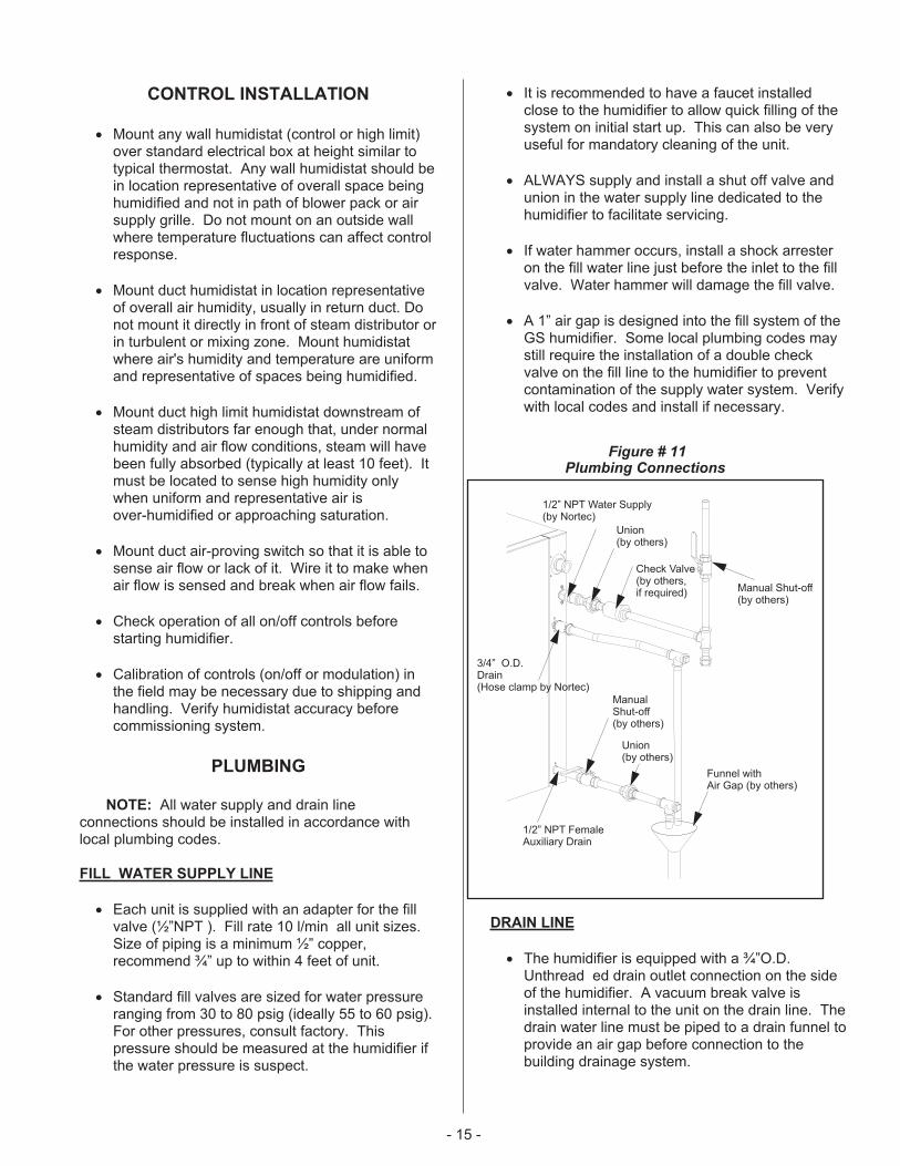
� A 1” air gap is designed into the fill system of theGS humidifier. Some local plumbing codes maystill require the installation of a double checkvalve on the fill line to the humidifier to preventcontamination of the supply water system. Verifywith local codes and install if necessary.
DRAIN LINE
� The humidifier is equipped with a ¾”O.D.Unthread ed drain outlet connection on the sideof the humidifier. A vacuum break valve isinstalled internal to the unit on the drain line. Thedrain water line must be piped to a drain funnel toprovide an air gap before connection to thebuilding drainage system.
- 15 -
1/2” NPT Water Supply(by Nortec)
Union(by others)
Check Valve(by others,if required) Manual Shut-off
(by others)
Funnel withAir Gap (by others)
Union(by others)
ManualShut-off(by others)
3/4” O.D.Drain(Hose clamp by Nortec)
1/2” NPT FemaleAuxiliary Drain
Figure # 11Plumbing Connections
� The drain line should not end in a sink usedfrequently by personnel, or where plumbingcodes prohibit it. Route to a floor drain orequivalent for safety reasons. Internal drain watertempering will ensure a maximum of 140ºF(60ºC) exiting water temperature.
� Never install PVC piping as a drain line material.Always use material suitable for with-standing140ºF (60ºC).
� Keep drain lines as short as possible. Keep drainlines sloped down, not level and not up since lowspots in drain lines will accumulate sediment andcause backup. The drain line should be 1-1.5"O.D. or larger. Consult local codes.
� When the drain pump is activated, the tank drainsat a rate of 7-8 gal/min (18-20 l/min).
AUX DRAIN PORT
� An auxiliary drain port is also provided on theside of the humidifier. It can be used to manuallydrain the unit, if required. The unit is shippedwith this connection plugged. It is recommendedto install a shut off valve on this line (see Figure#11).
� The auxiliary drain port is used when the freezeprotection option is required. Install a shut offvalve on this line and pipe to the drain funnel (seeFigure #11). The manual shut off valve mustalways be in the open position when the unit isoperating but can be closed for servicing of theunit.
STEAM LINES AND CONDENSATE LINE
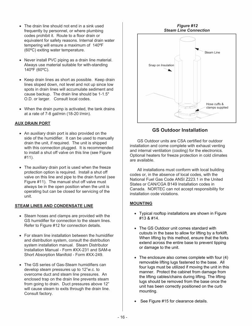
� Steam hoses and clamps are provided with theGS humidifier for connection to the steam lines.Refer to Figure #12 for connection details.
� For steam line installation between the humidifierand distribution system, consult the distributionsystem installation manual. Steam DistributorInstallation Manual - Form #XX-231 and SAM-eShort Absorption Manifold - Form #XX-249.
� The GS series of Gas-Steam humidifiers candevelop steam pressures up to 12”w.c. toovercome duct and steam line pressures. Anenclosed trap on the drain line prevents steamfrom going to drain. Duct pressures above 12”will cause steam to exits through the drain line.Consult factory.
GS Outdoor Installation
GS Outdoor units are CSA certified for outdoorinstallation and come complete with exhaust ventingand internal ventilation (cooling) for the electronics.Optional heaters for freeze protection in cold climatesare available.
All installations must conform with local buildingcodes or, in the absence of local codes, with theNational Fuel Gas Code ANSI Z223.1 in the UnitedStates or CAN/CGA B149 Installation codes inCanada. NORTEC can not accept responsibility forinstallation code violations.
MOUNTING
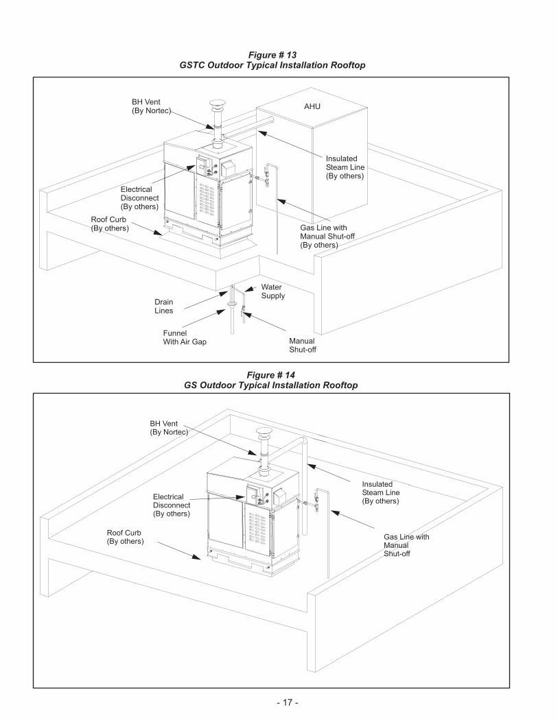
� Typical rooftop installations are shown in Figure#13 & #14.
� The GS Outdoor unit comes standard withcutouts in the base to allow for lifting by a forklift.When lifting by this method, ensure that the forksextend across the entire base to prevent tippingor damage to the unit.
� The enclosure also comes complete with four (4)removable lifting lugs fastened to the base. Allfour lugs must be utilized if moving the unit in thismanner. Protect the cabinet from damage fromthe lifting cables/chains during lifting. The liftinglugs should be removed from the base once theunit has been correctly positioned on the curbmounting.
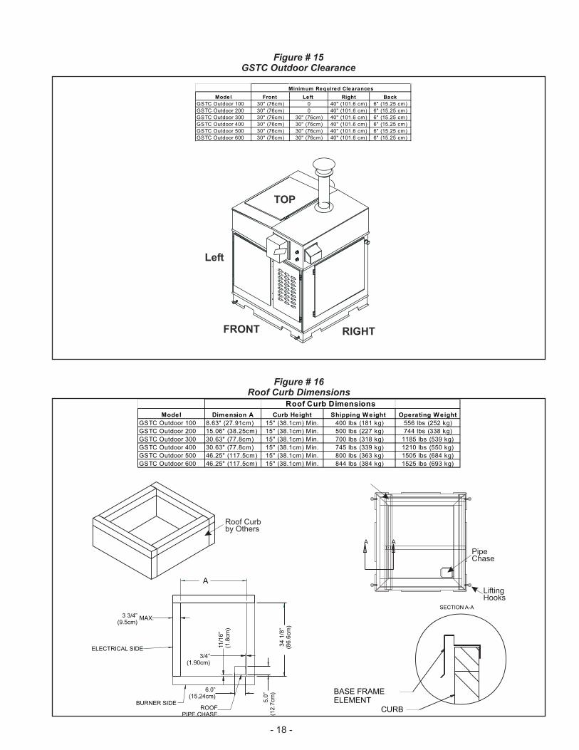
� See Figure #15 for clearance details.
- 16 -
Snap on Insulation
Steam Line
Hose cuffs &clamps supplied
Figure #12Steam Line Connection
- 17 -
BH Vent(By Nortec)
AHU
InsulatedSteam Line(By others)
Gas Line withManual Shut-off(By others)
WaterSupply
ManualShut-off
DrainLines
FunnelWith Air Gap
Roof Curb(By others)
ElectricalDisconnect(By others)
BH Vent(By Nortec)
InsulatedSteam Line(By others)
Gas Line withManualShut-off
ElectricalDisconnect(By others)
Roof Curb(By others)
Figure # 13GSTC Outdoor Typical Installation Rooftop
Figure # 14GS Outdoor Typical Installation Rooftop
- 18 -
FRONT RIGHT
TOP
Left
Minimum Required Clearances
Model Front Left Right Back
GSTC Outdoor 100 30" (76cm) 0 40" (101.6 cm) 6" (15.25 cm)
GSTC Outdoor 200 30" (76cm) 0 40" (101.6 cm) 6" (15.25 cm)
GSTC Outdoor 300 30" (76cm) 30" (76cm) 40" (101.6 cm) 6" (15.25 cm)
GSTC Outdoor 400 30" (76cm) 30" (76cm) 40" (101.6 cm) 6" (15.25 cm)
GSTC Outdoor 500 30" (76cm) 30" (76cm) 40" (101.6 cm) 6" (15.25 cm)
GSTC Outdoor 600 30" (76cm) 30" (76cm) 40" (101.6 cm) 6" (15.25 cm)
Figure # 15GSTC Outdoor Clearance
Figure # 16Roof Curb Dimensions
ROOFPIPE CHASE
ELECTRICAL SIDE
BURNER SIDE
BASE FRAMEELEMENT
CURB
34
1/8
”(8
6.6
cm
)
A
3 3/4”(9.5cm)
MAX.
11/1
6”
(1.8
cm
)
6.0”(15.24cm)
5.0
”(1
2.7
cm
)
AA
Roof Curbby Others
PipeChase
LiftingHooks
SECTION A-A
3/4”(1.90cm)
Roof Curb Dimensions
Model Dimension A Curb Height Shipping Weight Operating Weight
GSTC Outdoor 100 8.63" (27.91cm) 15" (38.1cm) Min. 400 lbs (181 kg) 556 lbs (252 kg)
GSTC Outdoor 200 15.06" (38.25cm) 15" (38.1cm) Min. 500 lbs (227 kg) 744 lbs (338 kg)
GSTC Outdoor 300 30.63" (77.8cm) 15" (38.1cm) Min. 700 lbs (318 kg) 1185 lbs (539 kg)
GSTC Outdoor 400 30.63" (77.8cm) 15" (38.1cm) Min. 745 lbs (339 kg) 1210 lbs (550 kg)
GSTC Outdoor 500 46.25" (117.5cm) 15" (38.1cm) Min. 800 lbs (363 kg) 1505 lbs (684 kg)
GSTC Outdoor 600 46.25" (117.5cm) 15" (38.1cm) Min. 844 lbs (384 kg) 1525 lbs (693 kg)
� The integral base of the GS Outdoor model isdesigned to mount on a curb. The curb must bebuilt to structurally support the entire weight ofthe humidifier when in operation. Required curbdimensions are given in Figure #16 .
� Ensure that the humidifier is mounted level.
� The pan in the bottom of all outdoor models hasa pipe chase for routing of services into thehumidifier from below.
� It is not necessary to make the hole in the roofthe same size as the curb. The curb drawingshows the location and size of the pipe chaserequired. The pipe chase should be sealed whenthe installation is complete to ensure positive ornegative pressure from the building.
� The panels of the outdoor model have louvers toprovide ventilation for the electronics and air forthe combustion process. Locate the unit so thatlouvered panels are a minimum of 10 ft from anymechanical exhaust outlet.
� When mounted on the curb, the lowest air intakelouvers must be a minimum of 12” above anysurface where snow or ice could accumulate. Inareas where normal snow accumulation ishigher, mount the unit accordingly.
� Do not store or use gasoline or other flammablevapors and liquids in the vicinity of the humidifier.
� The humidifier may be installed directly oncombustible flooring or, in the U.S., on woodflooring or Class A, Class B or Class C roofcovering materials.
GAS PIPING
� Installation of piping must be in accordance withlocal codes, and the National Fuel Gas CodeANSI Z223.1 in the United States orCAN/CGA-B149 Installation Codes in Canada.
� Refer to the indoor gas piping installationguidelines for gas line sizes, pressures, leaktesting procedures, and safety instructions.
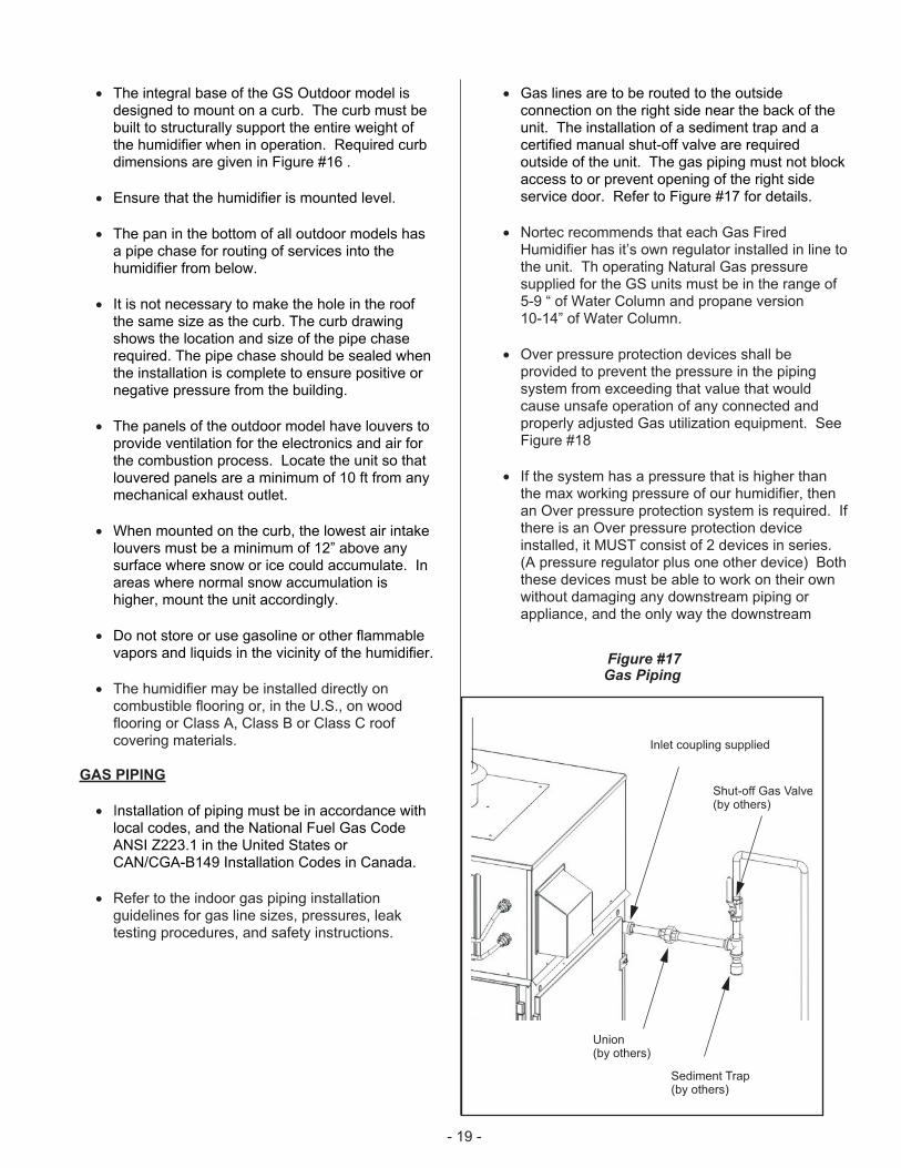
� Gas lines are to be routed to the outsideconnection on the right side near the back of theunit. The installation of a sediment trap and acertified manual shut-off valve are requiredoutside of the unit. The gas piping must not blockaccess to or prevent opening of the right sideservice door. Refer to Figure #17 for details.
� Nortec recommends that each Gas FiredHumidifier has it’s own regulator installed in line tothe unit. Th operating Natural Gas pressuresupplied for the GS units must be in the range of5-9 “ of Water Column and propane version10-14” of Water Column.
� Over pressure protection devices shall beprovided to prevent the pressure in the pipingsystem from exceeding that value that wouldcause unsafe operation of any connected andproperly adjusted Gas utilization equipment. SeeFigure #18
� If the system has a pressure that is higher thanthe max working pressure of our humidifier, thenan Over pressure protection system is required. Ifthere is an Over pressure protection deviceinstalled, it MUST consist of 2 devices in series.(A pressure regulator plus one other device) Boththese devices must be able to work on their ownwithout damaging any downstream piping orappliance, and the only way the downstream
- 19 -
Inlet coupling supplied
Shut-off Gas Valve(by others)
Union(by others)
Sediment Trap(by others)
Figure #17Gas Piping
system can be damaged is by the failure of bothdevices.
EXHAUST VENTING - OUTDOOR UNITS
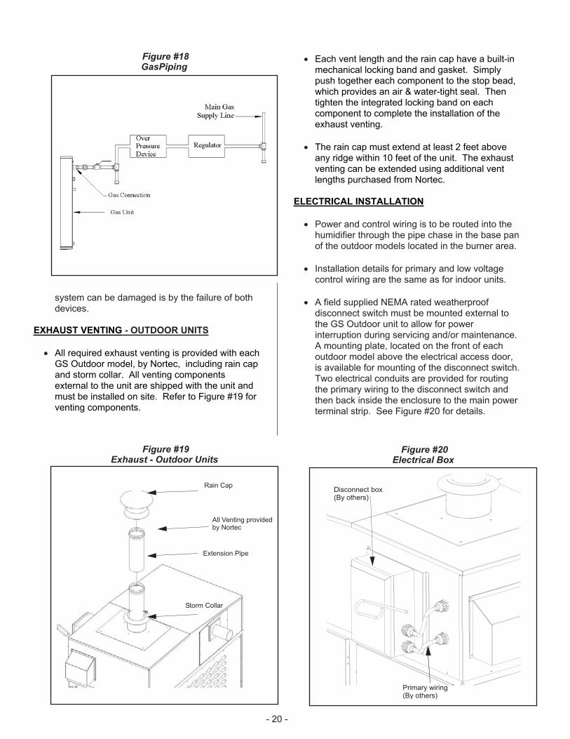
� All required exhaust venting is provided with eachGS Outdoor model, by Nortec, including rain capand storm collar. All venting componentsexternal to the unit are shipped with the unit andmust be installed on site. Refer to Figure #19 forventing components.
� Each vent length and the rain cap have a built-inmechanical locking band and gasket. Simplypush together each component to the stop bead,which provides an air & water-tight seal. Thentighten the integrated locking band on eachcomponent to complete the installation of theexhaust venting.
� The rain cap must extend at least 2 feet aboveany ridge within 10 feet of the unit. The exhaustventing can be extended using additional ventlengths purchased from Nortec.
ELECTRICAL INSTALLATION
� Power and control wiring is to be routed into thehumidifier through the pipe chase in the base panof the outdoor models located in the burner area.
� Installation details for primary and low voltagecontrol wiring are the same as for indoor units.
� A field supplied NEMA rated weatherproofdisconnect switch must be mounted external tothe GS Outdoor unit to allow for powerinterruption during servicing and/or maintenance.A mounting plate, located on the front of eachoutdoor model above the electrical access door,is available for mounting of the disconnect switch.Two electrical conduits are provided for routingthe primary wiring to the disconnect switch andthen back inside the enclosure to the main powerterminal strip. See Figure #20 for details.
- 20 -
Disconnect box(By others)
Primary wiring(By others)
Figure #20Electrical Box
All Venting providedby Nortec
Rain Cap
Extension Pipe
Storm Collar
Figure #19Exhaust - Outdoor Units
Figure #18GasPiping
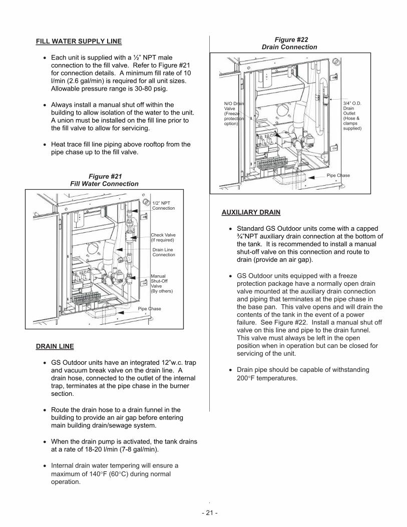
FILL WATER SUPPLY LINE
� Each unit is supplied with a ½” NPT maleconnection to the fill valve. Refer to Figure #21for connection details. A minimum fill rate of 10l/min (2.6 gal/min) is required for all unit sizes.Allowable pressure range is 30-80 psig.
� Always install a manual shut off within thebuilding to allow isolation of the water to the unit.A union must be installed on the fill line prior tothe fill valve to allow for servicing.
� Heat trace fill line piping above rooftop from thepipe chase up to the fill valve.
DRAIN LINE
� GS Outdoor units have an integrated 12”w.c. trapand vacuum break valve on the drain line. Adrain hose, connected to the outlet of the internaltrap, terminates at the pipe chase in the burnersection.
� Route the drain hose to a drain funnel in thebuilding to provide an air gap before enteringmain building drain/sewage system.
� When the drain pump is activated, the tank drainsat a rate of 18-20 l/min (7-8 gal/min).
� Internal drain water tempering will ensure a
maximum of 140�F (60�C) during normaloperation.
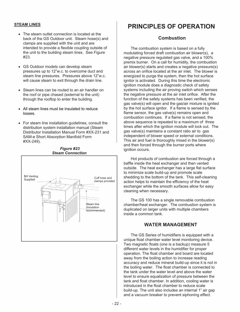
AUXILIARY DRAIN
� Standard GS Outdoor units come with a capped¾”NPT auxiliary drain connection at the bottom ofthe tank. It is recommended to install a manualshut-off valve on this connection and route todrain (provide an air gap).
� GS Outdoor units equipped with a freezeprotection package have a normally open drainvalve mounted at the auxiliary drain connectionand piping that terminates at the pipe chase inthe base pan. This valve opens and will drain thecontents of the tank in the event of a powerfailure. See Figure #22. Install a manual shut offvalve on this line and pipe to the drain funnel.This valve must always be left in the openposition when in operation but can be closed forservicing of the unit.
� Drain pipe should be capable of withstanding
200�F temperatures.
- 21 -
3/4” O.D.DrainOutlet(Hose &clampssupplied)
Pipe Chase
N/O DrainValve(Freezeprotectionoption)
Figure #22Drain Connection
1/2” NPTConnection
Check Valve(If required)
ManualShut-OffValve(By others)
Pipe Chase
Drain LineConnection
Figure #21Fill Water Connection
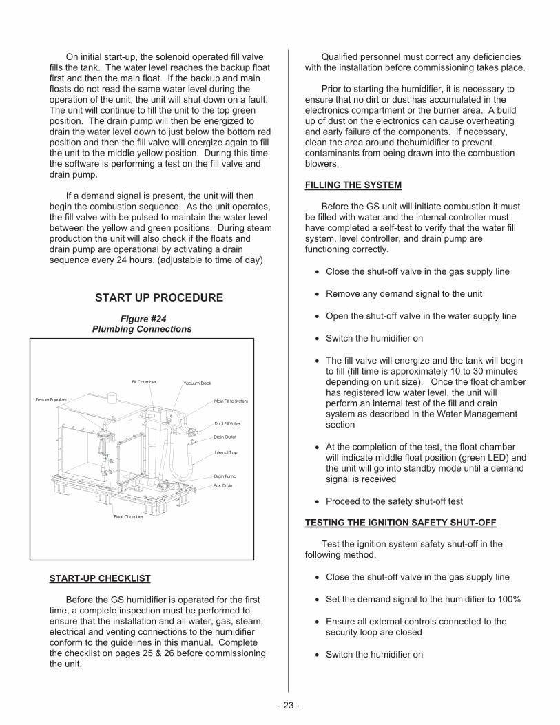
STEAM LINES
� The steam outlet connection is located at theback of the GS Outdoor unit. Steam hose(s) andclamps are supplied with the unit and areintended to provide a flexible coupling outside ofthe unit to the building steam lines. See Figure#23.
� GS Outdoor models can develop steampressures up to 12”w.c. to overcome duct andsteam line pressures. Pressures above 12”w.c.will cause steam to exit through the drain line.
� Steam lines can be routed to an air handler onthe roof or pipe chased (external to the unit)through the rooftop to enter the building.
� All steam lines must be insulated to reducelosses.
� For steam line installation guidelines, consult thedistribution system installation manual (SteamDistributor Installation Manual Form #XX-231 andSAM-e Short Absorption Manifold Form#XX-249).
PRINCIPLES OF OPERATION
Combustion
The combustion system is based on a fullymodulating forced draft combustion air blower(s), anegative pressure regulated gas valve, and a 100%premix burner. On a call for humidity, the combustionair blower(s) starts and creates a negative pressure(s)across an orifice located at the air inlet. The blower isenergized to purge the system, then the hot surfaceignitor is activated. During this time the electronicignition module does a diagnostic check of safetysystems including the air proving switch which sensesthe negative pressure at the air inlet orifice. After thefunction of the safety systems has been verified, thegas valve(s) will open and the gas/air mixture is ignitedby the hot surface ignitor. If a flame is sensed by theflame sensor, the gas valve(s) remains open andcombustion continues. If a flame is not sensed, theabove sequence is repeated to a maximum of threetimes after which the ignition module will lock out. Thegas valve(s) maintains a constant ratio air to gasindependent of blower speed or external conditions.This air and fuel is thoroughly mixed in the blower(s)and then forced through the burner ports whereignition occurs.
Hot products of combustion are forced through abaffle inside the heat exchanger and then ventedoutside. The heat exchanger has a large flat surfaceto minimize scale build-up and promote scaleshedding to the bottom of the tank. This self-cleaningaction helps to maintain the efficiency of the heatexchanger while the smooth surfaces allow for easycleaning when necessary.
The GS 100 has a single removable combustionchamber/heat exchanger. The combustion system isduplicated on larger units with multiple chambersinside a common tank.
WATER MANAGEMENT
The GS Series of humidifiers is equipped with aunique float chamber water level monitoring device.Two magnetic floats (one is a backup) measure 5different water levels in the humidifier for properoperation. The float chamber and board are locatedaway from the boiling action to increase readingaccuracy and reduce mineral build-up since it is not inthe boiling water. The float chamber is connected tothe tank under the water level and above the waterlevel to ensure equalization of pressure between thetank and float chamber. In addition, cooling water isintroduced in the float chamber to reduce scalebuild-up. The unit also includes an internal 1” air gapand a vacuum breaker to prevent siphoning effect.
- 22 -
Cuff hose andclamps provided
Steam line(Insulationrecommended)
BH VentingSupplied
Figure #23Steam Connection
On initial start-up, the solenoid operated fill valvefills the tank. The water level reaches the backup floatfirst and then the main float. If the backup and mainfloats do not read the same water level during theoperation of the unit, the unit will shut down on a fault.The unit will continue to fill the unit to the top greenposition. The drain pump will then be energized todrain the water level down to just below the bottom redposition and then the fill valve will energize again to fillthe unit to the middle yellow position. During this timethe software is performing a test on the fill valve anddrain pump.
If a demand signal is present, the unit will thenbegin the combustion sequence. As the unit operates,the fill valve with be pulsed to maintain the water levelbetween the yellow and green positions. During steamproduction the unit will also check if the floats anddrain pump are operational by activating a drainsequence every 24 hours. (adjustable to time of day)
START UP PROCEDURE
START-UP CHECKLIST
Before the GS humidifier is operated for the firsttime, a complete inspection must be performed toensure that the installation and all water, gas, steam,electrical and venting connections to the humidifierconform to the guidelines in this manual. Completethe checklist on pages 25 & 26 before commissioningthe unit.
Qualified personnel must correct any deficiencieswith the installation before commissioning takes place.
Prior to starting the humidifier, it is necessary toensure that no dirt or dust has accumulated in theelectronics compartment or the burner area. A buildup of dust on the electronics can cause overheatingand early failure of the components. If necessary,clean the area around thehumidifier to preventcontaminants from being drawn into the combustionblowers.
FILLING THE SYSTEM
Before the GS unit will initiate combustion it mustbe filled with water and the internal controller musthave completed a self-test to verify that the water fillsystem, level controller, and drain pump arefunctioning correctly.
� Close the shut-off valve in the gas supply line
� Remove any demand signal to the unit
� Open the shut-off valve in the water supply line
� Switch the humidifier on
� The fill valve will energize and the tank will beginto fill (fill time is approximately 10 to 30 minutesdepending on unit size). Once the float chamberhas registered low water level, the unit willperform an internal test of the fill and drainsystem as described in the Water Managementsection
� At the completion of the test, the float chamberwill indicate middle float position (green LED) andthe unit will go into standby mode until a demandsignal is received
� Proceed to the safety shut-off test
TESTING THE IGNITION SAFETY SHUT-OFF
Test the ignition system safety shut-off in thefollowing method.
� Close the shut-off valve in the gas supply line
� Set the demand signal to the humidifier to 100%
� Ensure all external controls connected to thesecurity loop are closed
� Switch the humidifier on
- 23 -
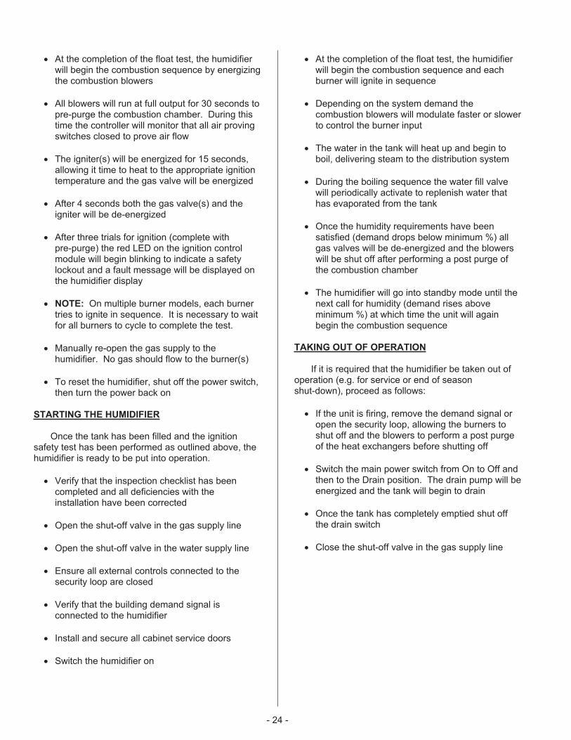
Float Chamber
Presure Equalizer
Aux. Drain
Drain Pump
Dual Fill Valve
Drain Outlet
Vacuum BreakFill Chamber
Main Fill to System
Internal Trap
Figure #24Plumbing Connections
� At the completion of the float test, the humidifierwill begin the combustion sequence by energizingthe combustion blowers
� All blowers will run at full output for 30 seconds topre-purge the combustion chamber. During thistime the controller will monitor that all air provingswitches closed to prove air flow
� The igniter(s) will be energized for 15 seconds,allowing it time to heat to the appropriate ignitiontemperature and the gas valve will be energized
� After 4 seconds both the gas valve(s) and theigniter will be de-energized
� After three trials for ignition (complete withpre-purge) the red LED on the ignition controlmodule will begin blinking to indicate a safetylockout and a fault message will be displayed onthe humidifier display
� NOTE: On multiple burner models, each burnertries to ignite in sequence. It is necessary to waitfor all burners to cycle to complete the test.
� Manually re-open the gas supply to thehumidifier. No gas should flow to the burner(s)
� To reset the humidifier, shut off the power switch,then turn the power back on
STARTING THE HUMIDIFIER
Once the tank has been filled and the ignitionsafety test has been performed as outlined above, thehumidifier is ready to be put into operation.
� Verify that the inspection checklist has beencompleted and all deficiencies with theinstallation have been corrected
� Open the shut-off valve in the gas supply line
� Open the shut-off valve in the water supply line
� Ensure all external controls connected to thesecurity loop are closed
� Verify that the building demand signal isconnected to the humidifier
� Install and secure all cabinet service doors
� Switch the humidifier on
� At the completion of the float test, the humidifierwill begin the combustion sequence and eachburner will ignite in sequence
� Depending on the system demand thecombustion blowers will modulate faster or slowerto control the burner input
� The water in the tank will heat up and begin toboil, delivering steam to the distribution system
� During the boiling sequence the water fill valvewill periodically activate to replenish water thathas evaporated from the tank
� Once the humidity requirements have beensatisfied (demand drops below minimum %) allgas valves will be de-energized and the blowerswill be shut off after performing a post purge ofthe combustion chamber
� The humidifier will go into standby mode until thenext call for humidity (demand rises aboveminimum %) at which time the unit will againbegin the combustion sequence
TAKING OUT OF OPERATION
If it is required that the humidifier be taken out ofoperation (e.g. for service or end of seasonshut-down), proceed as follows:
� If the unit is firing, remove the demand signal oropen the security loop, allowing the burners toshut off and the blowers to perform a post purgeof the heat exchangers before shutting off
� Switch the main power switch from On to Off andthen to the Drain position. The drain pump will beenergized and the tank will begin to drain
� Once the tank has completely emptied shut offthe drain switch
� Close the shut-off valve in the gas supply line
- 24 -
- 25 -
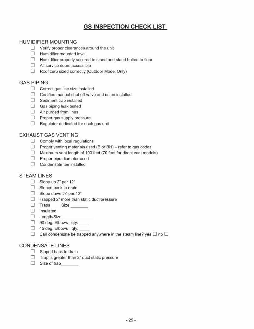
GS INSPECTION CHECK LIST
HUMIDIFIER MOUNTING� Verify proper clearances around the unit
� Humidifier mounted level
� Humidifier properly secured to stand and stand bolted to floor
� All service doors accessible
� Roof curb sized correctly (Outdoor Model Only)
GAS PIPING� Correct gas line size installed
� Certified manual shut off valve and union installed
� Sediment trap installed
� Gas piping leak tested
� Air purged from lines
� Proper gas supply pressure
� Regulator dedicated for each gas unit
EXHAUST GAS VENTING� Comply with local regulations
� Proper venting materials used (B or BH) – refer to gas codes
� Maximum vent length of 100 feet (70 feet for direct vent models)
� Proper pipe diameter used
� Condensate tee installed
STEAM LINES� Slope up 2” per 12”
� Sloped back to drain
� Slope down ½” per 12”
� Trapped 2” more than static duct pressure
� Traps Size _______
� Insulated
� Length/Size ____________
� 90 deg. Elbows qty: ____
� 45 deg. Elbows qty: ____
� Can condensate be trapped anywhere in the steam line? yes� no�
CONDENSATE LINES� Sloped back to drain
� Trap is greater than 2” duct static pressure
� Size of trap_______

- 26 -
SUPPLY WATER LINE� Nortec supplied adapter installed on fill valve (½”NPT)
� Manual shut off valve and union installed
� Verified pressure (30 – 80 psig)
� Water source of 10 l/min (2.6 gpm)
� Leak tested
� ½” dia. At max 4ft of the unit
DRAIN LINES� Air gap located within 3ft of the unit
� Minimum drain line size of 1” in dia.� Downward slope
� Tundish (funnel) installed to provide air gap
� Temperature rating of piping
� Hose connections tightened
� Auxiliary drain piped with shut off valve to tundish
WATER QUALITY- Well water� - City water� - Softened water� - RO/DI water�
Conductivity:_______mhmos Hardness: _______GPG Silica____ppm Chlorides:_______ppm
pH:_______
NOTE: Failure due to chloride corrosion is not covred under Nortec’s standard warranty. Consult factory for
more information.
ELECTRICAL INSTALLATION� Comply with local regulations
� Proper supply voltage (must match rating plate) and breaker size
� Electrical disconnect switch close to humidifier
� Cables properly affixed
� Low voltage wiring & control signal(s) wired to correct terminals
� Humidifier configured for correct control signal(s)
TYPE OF CONTROLS INSTALLED/ LOCATION/ WIRING/ SETTING� High Limit ______________________________� Air Proving _____________________________� Modulation Control________________________� On/Off Control ___________________________� Controls by Nortec________________________� Controls by Others________________________

� Close the shut-off valve in the water supply line
� Isolate the humidifier from the electrical powersupply at the main disconnect switch
SCALE MANAGEMENT
The gas humidifier will periodically “blowdown”water from the tank to reduce the concentration of totaldissolved solids that accumulate during long termoperation. Gas Humidifiers are shipped factory setwith a blowdown of 25%. This setting ensures thatscale build-up will be minimized for all waterconditions.
Once the water conditions are known, theblowdown rate can be adjusted by software (GSTCmodels) or by using dip switches on the logic controlboard (GSP models).
Another effective means of controlling the amountof scale in the tank is with the use of the Full TankBlowdown (FTBD) built into the software. When thisfeature is activated, the drain pump will be energizedto drain the entire contents of the tank and then thetank will be refilled with fresh water, thus keeping theamount of total dissolved solids to a minimum. Thefeature can be programmed in the software to occurafter a specific amount of operating time and can alsobe triggered by a signal sent to the humidifier from abuilding management system.
WATER QUALITY
Due to the wide range of water conditions foundthroughout North America it is important that theblowdown is set according to the local waterconditions. By water conditions we are referring to thehardness of the water supplied to the humidifier. Thehardness is measured in grains per gallon. It is alsoimportant to test for silica content. Silicates may causefoaming and contribute to scale buildup in thehumidifier tank and float chamber.
If you are unaware of the hardness or silicacontent of your water supply, there are many “do ityourself” kits which can be purchased, or there areseveral companies that will perform the tests for areasonable price. You can even contact yourmunicipality for your water condition or order theNORTEC water test kit.
Note: Water quality conditions resulting incomponent failures are not covered under NORTEC’sstandard warranty.
� Silica Test: Measured in ppm (parts per million)Follow the directions with the kit. A high readingwill decrease the performance of your system.The recommended operating range for silica is 0ppm to 14 ppm. Note: A high silica content alongwith a high hardness content may increase theservice intervals of the system . Consult thefactory if this condition exists at the site.
� Hardness: Measured in gpg (grains per gallon).Follow the instructions on each individuallywrapped test strip and use the colour chartprovided. The recommended operating range forhardness is 0 gpg to 12 gpg. Note: Highhardness along with high silica may increase theservice intervals of the system. Consult thefactory if this condition exists at the site.
� pH: Follow the directions on the test strip bottle.The recommended operating range for pH is 6.5to 7.5 on the colour scale. Consult the factory ifoutside these parameters.
� Chlorides: Measured in ppm (parts per million).Follow the directions on the test strip bottle. Therecommended level for chlorides is not to exceed25 ppm.
NOTE: Failure due to chloride corrosion
is not covred under Nortec’s standard warranty.
Consult factory for more information.
� High levels of chlorides will attack stainless steel.Consult the factory for additional information ifyour water contain high levels of chlorides.
- 27 -
Figure #25Site Water Test Kit P/N 1507214

� Conductivity: Measured in micromhos. Followthe directions for the conductivity pen foundinside the box. Multiply the digital reading by 1.5.The recommended operating range forconductivity is 0 - 1500 micromhos. Consult thefactory is you measure outside these parameters.
Tech-nology
WaterType
WaterCond.
Range
Hard-nessRange
SilicaRange
Alkalin.Range
Chlor.Range
Gas-Fired
Micromhos
GPG PPM pH PPM
Potable 0-1500 0-12 0-14 6.5-7.5 0-25
Treated 0-100 0-1 0-1 7-7.5 0-25
� NORTEC recommends performing a semi-annualwater analysis to ensure optimal performance.
� The humidifier is intended to operate on coldpotable tap water.
� DO NOT use a hot water source to supply thehumidifier. Minerals will adhere more easily tosurfaces and the fill valve's small flow regulatingorifice could become plugged.
� Consider using a water softener. Longeroperating times between tank cleaning will bereached on softened water.
� Reverse osmosis (RO) water can provide verylong times before cleaning is required since it iscleaner than softened water. Deionized (DI)water may be used with all models. Consult yourNORTEC representative for quote on a watertreatment system.
SAFETY INSTRUCTIONS
Refer to front cover and page 1 of this guide.
FAULT CONDITIONS
This appliance is equipped with a self diagnosticignition module which identifies a fault code when itoccurs. Refer to the fault & warning list on pg 60.
GSTC MODELS
Faults are indicated with a fault message on thedisplay of GSTC models. Recovery from lockoutrequires resetting of the humidifier. This can beachieved by momentarily shutting off the power switchthen turning it back on, or by pressing the reset buttonon the logic control board mounted inside the electricalcabinet.
A history of all faults is stored in memory ofthe software and can be viewed through the servicelevel on the display. Refer to the keypad display menustructure at the end of the manual.
GSP MODELS
Faults are indicated on GSP models with a faultcode on the small display screen attached to the logiccontrol board. The display can be viewed by removingthe front electrical door. Check the display for the faultcode before shutting off power to the unit. Resettingthe humidifier clears the fault. This can be achievedby shutting off the power switch, then turning it backon, or by pressing the reset button on the logic controlboard. A list of all fault codes and the type of fault theyrepresent is located near the back of the manual.
MAINTENANCE
To ensure proper performance and long operatinglife of the GS humidifier, it is recommended that theappliance and installation be inspected at least once ayear by a qualified service person. A propermaintenance schedule should be followed. Since theamount and type of maintenance required is generallyas a result of how much the humidifier operates, all GShumidifiers monitor the amount of steam producedover time and will indicate when service is required.All units come factory set with a service interval of 500hours. This service interval can be adjusted throughsoftware (GSTC models) or by dip switch settings(GSP models) on the logic control board.
All maintenance work must be performed byexperienced and trained personnel.
Periodic cleaning of the screens in the ventterminal (where applicable) is recommended.
NOTE Use only NORTEC original parts toreplace damaged or defective components. Failure todo so may cause improper operation of the humidifierand will void warranty.
DRAINING THE TANK
� During extended periods of inactivity such as offseason or periods of very low demand, it isadvisable to drain the water from the tank. On allmodels this is accomplished by switching the unitto “Drain”.
� Do not remove the front clean out port on thetank until the unit has completely drained. On GS300-600 units do not remove the top clean outports on the tank unless the water has cooled orthe unit has completely drained.
- 28 -
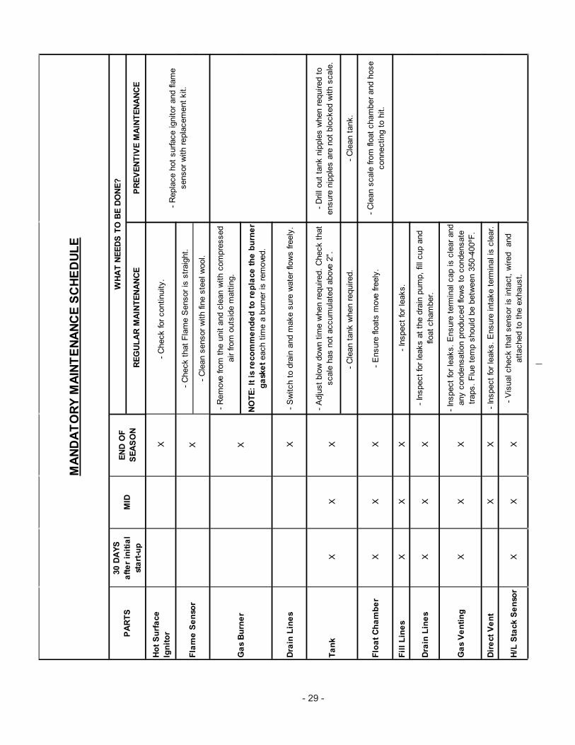
RE
GU
LA
RM
AIN
TE
NA
NC
EP
RE
VE
NT
IVE
MA
INT
EN
AN
CE
Ho
tS
urf
ace
Ign
ito
rX
-C
heck
for
continuity.
-C
heck
that
Fla
me
Sensor
isstr
aig
ht.
-C
lean
sensor
with
fine
ste
elw
ool.
-R
em
ove
from
the
unit
and
cle
an
with
com
pre
ssed
air
from
outs
ide
matt
ing.
NO
TE
:It
isre
co
mm
en
de
dto
rep
lace
the
bu
rne
r
ga
ske
teach
tim
ea
burn
er
isre
move
d.
Dra
inL
ine
sX
-S
witch
todra
inand
make
sure
wate
rflo
ws
freely
.
-A
dju
st
blo
wdow
ntim
ew
hen
required.
Check
that
scale
has
not
accum
ula
ted
above
2".
-D
rill
out
tank
nip
ple
sw
hen
required
to
ensure
nip
ple
sare
not
blo
cked
with
scale
.
-C
lean
tank
when
required.
-C
lean
tank.
Flo
at
Ch
am
be
rX
XX
-E
nsure
floats
move
freely
.-
Cle
an
scale
from
float
cham
ber
and
hose
connecting
tohit.
Fil
lL
ine
sX
XX
-In
spect
for
leaks.
Dra
inL
ine
sX
XX
-In
spect
for
leaks
at
the
dra
inpum
p,
fillcup
and
float
cham
ber.
Ga
sV
en
tin
gX
XX
-In
spect
for
leaks.
Ensure
term
inalcap
iscle
ar
and
any
condensation
pro
duced
flow
sto
condensate
traps.
Flu
ete
mp
should
be
betw
een
350-4
00ºF
.
Dir
ect
Ve
nt
XX
-In
spect
for
leaks.
Ensure
inta
ke
term
inalis
cle
ar.
H/L
Sta
ck
Se
nso
rX
XX
-V
isualcheck
that
sensor
isin
tact,
wired
and
att
ached
toth
eexhaust.
-R
epla
ce
hot
surface
ignitor
and
flam
e
sensor
with
repla
cem
ent
kit.
MA
ND
AT
OR
YM
AIN
TE
NA
NC
ES
CH
ED
UL
E
WH
AT
NE
ED
ST
OB
ED
ON
E?
Fla
me
Se
nso
r
XX
X
XT
an
k
EN
DO
F
SE
AS
ON
MID
30
DA
YS
aft
er
init
ial
sta
rt-u
p
PA
RT
S
X
Ga
sB
urn
er
- 29 -

� Ensure that power is switched on again duringperiods of demand.
� The GSTC model of the Gas Steam humidifierincludes a pre-cleaning sequence feature. Whenactivated (through the keypad), the unit will flushthe humidifier, refill with cold water, and flushagain reducing the scale accumulated at thebottom of the tank.
CLEANING THE STEEL TANK
CAUTION: Water and scale may be hot enoughto cause burns. Turn off humidifier and allow it to coolbefore cleaning.
It is recommended that the tank be cleaned atleast once every season to maintain optimumoperation. It may be necessary to increase thefrequency of cleaning or increase the blowdownsetting in areas of hard water or prolonged annualusage (see the Blowdown Setting section of thismanual).
Cleaning of the humidifier is mandatory and mustbe performed on a regular basis.
To reduce cleaning time, use the pre-cleaningsequence on the GSTC model to help evacuatemineral debris from the unit. Check the controlleroperation to activate this feature.
The combustion chamber walls are usually selfcleaning. The mineral buildup flakes off, due to theexpansion and contraction and violent boiling actionduring on/off cycles, and settles to the bottom of thetank. The combustion end block will have scale buildup, as will the heat transfer tubes. These surfacesmust be cleaned at regular intervals.
Frontal port cleaning will be done through the frontdoor of the unit. Remove cabinet door on the left ofthe LCD display using a Philips screwdriver. Removethe side tank port opening, by removing the 3 / 16 nuts(½” key or socket is needed).
Additional clean out ports are available on the topof the 300/400 and 500/600 lb/h tanks. To accessthese ports, remove the top cabinet panel using aPhillips screwdriver. Remove the top clean out portsmy removing the nuts.
Removal of the heat exchanger(s) is notnecessary to clean the inside of the tank.
Scoop out loose scale with a small shovel such asthose used for gardening. Once loose scale isremoved, use a scraper such as a plastic windshieldscraper to remove scale adhering to the tank or heat
exchanger walls. DO NOT use a metal scraper thatwill scratch the stainless steel surfaces of the tank.Once all large pieces of scale have been removed,vacuum the tank out with a shop vacuum, fill part waywith water, and flush remaining sediment from the tankthrough the drain.
Due to the presence of polymer gaskets aroundthe heat exchanger, do not use any harsh cleaningchemicals. Please consult NORTEC prior to using anychemicals. Once the lid has been replaced, fill the unitwith water and examine for leaks.
Inspect the drain and fill lines assembly for scalebuild-up and if necessary remove them from thehumidifier for cleaning. If the blowdown assemblybecomes blocked, scale build-up in the tank will beaccelerated and damage to the humidifier could result.The drain pump may be opened and cleaned. ConsultNORTEC for proper procedure.
Reassemble the drain and blowdown if they wereremoved. Re-install tank top and side lids making suretank cover gasket is intact. Do not over tighten holddown nuts. If using a torque wrench do not exceed50 in/lb (5ft/lb). Re-seal all cabinet lids.
Cleaning the float chamber is accomplished byremoving the hold down screws to access the floatsand using a small brush to gently clean the scale fromthe floats and chamber. Ensure that floats are back inplace and o-ring is properly seated before tighteningscrews on float chamber. Special attention must beused when removing or re-installing the float chamber.
- 30 -
Torque: 50 in-LB (5.7 NM)
Figure #26Cleaning Tank Access
The switch board must be replaced into the sameposition as before cleaning and the tie -wrap must beused to hold the float chamber in position.
SERVICING THE UNIT
Caution: Disconnect power before servicing thisappliance.
Caution: Label all wires prior to disconnectionwhen servicing controls. Wiring errors can causeimproper and dangerous operation.
The combustion chamber, heat exchanger andflue baffles are all fabricated from stainless steel anddo not require internal cleaning.
Should the main burner fail to light, or flame is notdetected during the first trial for ignition period, the gasvalve is de-energized and the control goes through aninterpurge delay before another ignition attempt. Thecontrol will attempt two additional ignition trials beforegoing into lockout. The valve relay will bede-energized immediately, and the combustion blowerwill be turned off.
SERVICE CHECKS
COMBUSTION BLOWER
The combustion air blower motors arepermanently lubricated and do not require lubrication.Clean out any dust that has accumulated in the blowerhousing using an air gun.
BURNER
The burners are made of ceramic fabric materialand operate in the infrared mode. Depending on theenvironment, the burner(s) may require removal of lintor grease-laden dust periodically. This may beachieved by removing the burner and applyingpressurized air to the external surface of the material.Refer to the Servicing Section related to burnerremoval.
Flame Sensor
Flame current is the current which passes throughthe flame from the sensor to ground. The ignitionmodule must detect a minimum flame current of 0.7microamps or a flame proving lockout will occur. Tomeasure flame current, connect an DC micrometer tothe FC- FC+ terminals on the module. Meter shouldread 0.7 uA or higher. If meter reads below “0” onscale, meter leads are reversed. Disconnect powerand reconnect meter leads for proper polarity.
NOTE: Proper polarity of supply voltage to theunit is necessary for flame sensing to occur. Oxidationon flame sensing rod can reduce measured current.The oxidation can be cleaned from the sensing rodusing steel wool or an emery cloth.
Igniter Check
If the igniter is suspected of being defective thenthe following test may be carried out;
1. Ensure that the power and gas is switched offbefore servicing.
2. To test the igniter, disconnect the igniter leadsfrom their terminal connections.
3. Using a multimeter set the Ohm’s scale andplace one of the meter leads on one of theigniter wire ends and the other meter lead onthe end of the other igniter wire.
Gas Valve Setting
The gas valves used in the GS series humidifierare negative-pressure-regulated valves. The valvesetting listed on the product rating plate is shownrelative to atmosphere – this setting will always remainconstant.
The valves come preset from the factory for thecorrect gas type. If an adjustment is required, use thefollowing steps:
1. Remove the screw from the pressure portmarked “out” on the back side of the gasvalve.
2. Connect a hose from a digital manometer (oran inclined manometer capable of readingbelow 0.1”w.c.) to the “out” pressure port.
3. Activate the humidifier and measure the gasvalve pressure once the valve is energizedand a flame is established in the combustionchamber. Verify this pressure to the pressurelisted on the unit specification label.
4. If the pressure needs adjusting, remove thelocking cap on the top of the gas valve.
5. Below the locking cap is an adjustment screw.Increase the pressure by turning theadjustment screw clockwise, decrease byturning counter-clockwise.
NOTE: The pressure will fluctuate slightly asthe unit operates, especially with verysensitive measuring devices. Use the meanpressure value as the set pressure.
- 31 -

6. Once the pressure has been adjusted, replacethe locking cap.
7. Replace the screw in the “out” pressure portand tighten firmly.
COMPONENT REPLACEMENT
CONSULT FACTORY PRIOR TO THE
REPLACEMENT OF ANY COMPONENT.
All service work must be performed byexperienced and trained personnel.
Only use original NORTEC spare parts to replacedefective components. Damage caused bynon-approved parts is not covered under NORTEC’sstandard warranty.
Hot Surface Igniter and Flame Sensor
Replacement
1. Shut off electrical power and gas supply to thehumidifier.
2. Remove the right side service access door.
3. Disconnect all wiring to the igniter and flamesensor.
4. Unscrew the fixing nuts for the igniter andflame sensor. Carefully remove the igniter andflame sensor.
5. Reverse the sequence above to install the newigniter and flame sensor. Always install a new
gasket when replacing the flame sensor andigniter.
CAUTION: The silicon carbide igniter isbreakable. Handle with great care to avoiddamage.
Burner Removal and Installation
1. Shut off electrical power and gas supply to thehumidifier.
2. Remove the right side service access door.
3. Disconnect all wiring to the combustionblower, gas valve, air proving switch, igniterand flame sensor (note the connectorassignment).
4. Undo the union on the flexible gas hose anddisconnect the gas hose from the gas valve.
5. Undo the 4 nuts on the blower outlet andremove blower, leaving the gas valve/air inletassembly and the fan-board mounting bracket(if present) mounted to the blower.
6. Undo the 4 large nuts that secure the burnermounting plate to the face of the heatexchanger and carefully remove the burnerassembly. Handle the burner only by themetal surfaces. Do not grip the ceramicmatting as grease, dust or dirt can affect theperformance of the burner.
7. Reverse the sequence above to re-install theburner after cleaning or, if necessary, replace
- 32 -
Hold Burner only on metal pipe
Ceramic Matting DO NOT TOUCH!
Figure #28Burner Assembly
Figure #27Flame Sensor and Ignitor Assembly
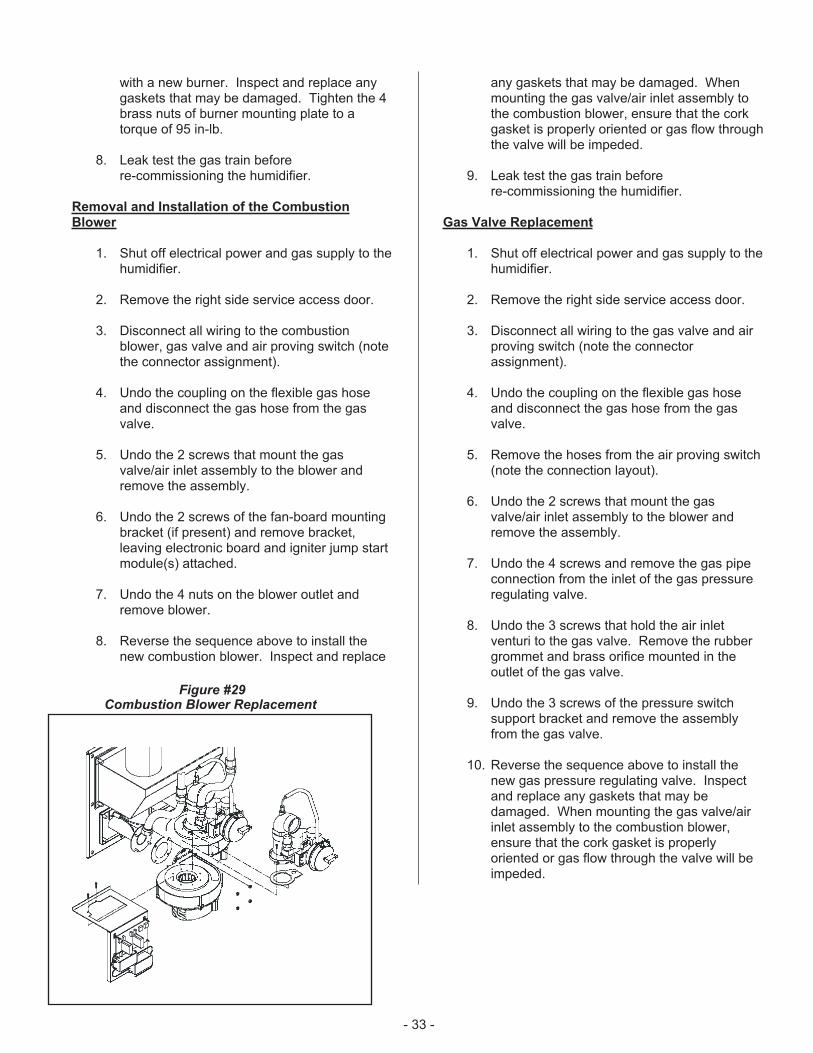
with a new burner. Inspect and replace anygaskets that may be damaged. Tighten the 4brass nuts of burner mounting plate to atorque of 95 in-lb.
8. Leak test the gas train beforere-commissioning the humidifier.
Removal and Installation of the Combustion
Blower
1. Shut off electrical power and gas supply to thehumidifier.
2. Remove the right side service access door.
3. Disconnect all wiring to the combustionblower, gas valve and air proving switch (notethe connector assignment).
4. Undo the coupling on the flexible gas hoseand disconnect the gas hose from the gasvalve.
5. Undo the 2 screws that mount the gasvalve/air inlet assembly to the blower andremove the assembly.
6. Undo the 2 screws of the fan-board mountingbracket (if present) and remove bracket,leaving electronic board and igniter jump startmodule(s) attached.
7. Undo the 4 nuts on the blower outlet andremove blower.
8. Reverse the sequence above to install thenew combustion blower. Inspect and replace
any gaskets that may be damaged. Whenmounting the gas valve/air inlet assembly tothe combustion blower, ensure that the corkgasket is properly oriented or gas flow throughthe valve will be impeded.
9. Leak test the gas train beforere-commissioning the humidifier.
Gas Valve Replacement
1. Shut off electrical power and gas supply to thehumidifier.
2. Remove the right side service access door.
3. Disconnect all wiring to the gas valve and airproving switch (note the connectorassignment).
4. Undo the coupling on the flexible gas hoseand disconnect the gas hose from the gasvalve.
5. Remove the hoses from the air proving switch(note the connection layout).
6. Undo the 2 screws that mount the gasvalve/air inlet assembly to the blower andremove the assembly.
7. Undo the 4 screws and remove the gas pipeconnection from the inlet of the gas pressureregulating valve.
8. Undo the 3 screws that hold the air inletventuri to the gas valve. Remove the rubbergrommet and brass orifice mounted in theoutlet of the gas valve.
9. Undo the 3 screws of the pressure switchsupport bracket and remove the assemblyfrom the gas valve.
10. Reverse the sequence above to install thenew gas pressure regulating valve. Inspectand replace any gaskets that may bedamaged. When mounting the gas valve/airinlet assembly to the combustion blower,ensure that the cork gasket is properlyoriented or gas flow through the valve will beimpeded.
- 33 -
Figure #29Combustion Blower Replacement
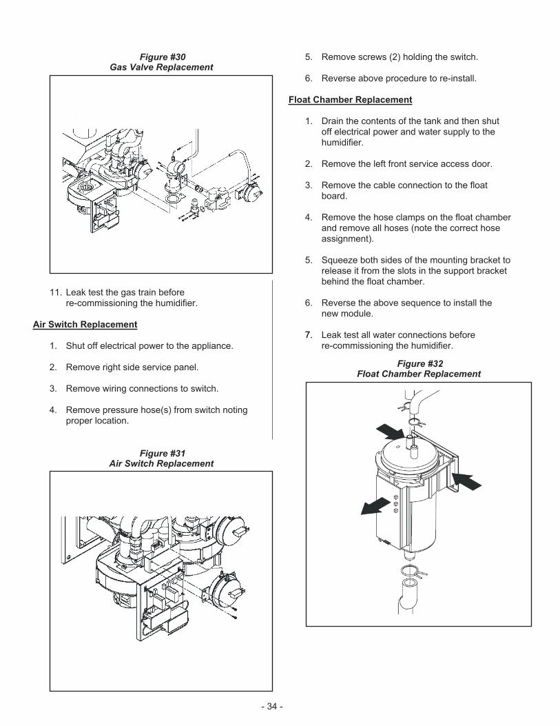
11. Leak test the gas train beforere-commissioning the humidifier.
Air Switch Replacement
1. Shut off electrical power to the appliance.
2. Remove right side service panel.
3. Remove wiring connections to switch.
4. Remove pressure hose(s) from switch notingproper location.
5. Remove screws (2) holding the switch.
6. Reverse above procedure to re-install.
Float Chamber Replacement
1. Drain the contents of the tank and then shutoff electrical power and water supply to thehumidifier.
2. Remove the left front service access door.
3. Remove the cable connection to the floatboard.
4. Remove the hose clamps on the float chamberand remove all hoses (note the correct hoseassignment).
5. Squeeze both sides of the mounting bracket torelease it from the slots in the support bracketbehind the float chamber.
6. Reverse the above sequence to install thenew module.
7.7. Leak test all water connections beforere-commissioning the humidifier.
- 34 -
Figure #32Float Chamber Replacement
Figure #31Air Switch Replacement
Figure #30Gas Valve Replacement
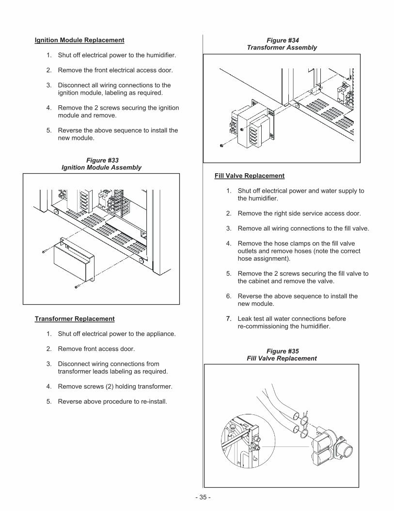
Ignition Module Replacement
1. Shut off electrical power to the humidifier.
2. Remove the front electrical access door.
3. Disconnect all wiring connections to theignition module, labeling as required.
4. Remove the 2 screws securing the ignitionmodule and remove.
5. Reverse the above sequence to install thenew module.
Transformer Replacement
1. Shut off electrical power to the appliance.
2. Remove front access door.
3. Disconnect wiring connections fromtransformer leads labeling as required.
4. Remove screws (2) holding transformer.
5. Reverse above procedure to re-install.
Fill Valve Replacement
1. Shut off electrical power and water supply tothe humidifier.
2. Remove the right side service access door.
3. Remove all wiring connections to the fill valve.
4. Remove the hose clamps on the fill valveoutlets and remove hoses (note the correcthose assignment).
5. Remove the 2 screws securing the fill valve tothe cabinet and remove the valve.
6. Reverse the above sequence to install thenew module.
7.7. Leak test all water connections beforere-commissioning the humidifier.
- 35 -
Figure #34Transformer Assembly
Figure #33Ignition Module Assembly
Figure #35Fill Valve Replacement
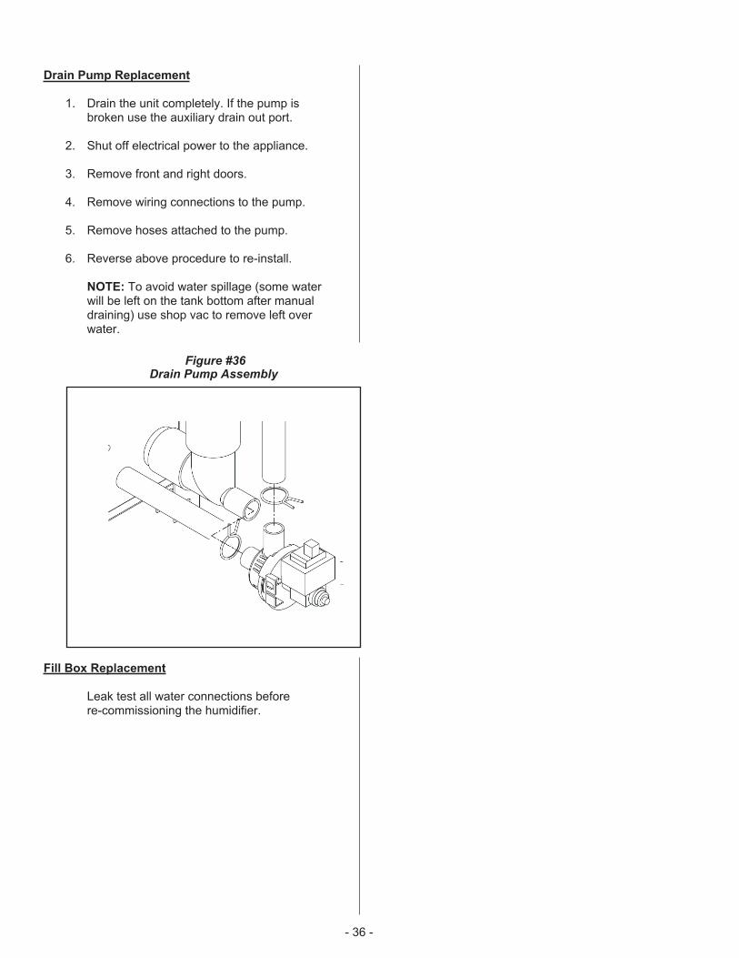
Drain Pump Replacement
1. Drain the unit completely. If the pump isbroken use the auxiliary drain out port.
2. Shut off electrical power to the appliance.
3. Remove front and right doors.
4. Remove wiring connections to the pump.
5. Remove hoses attached to the pump.
6. Reverse above procedure to re-install.
NOTE: To avoid water spillage (some waterwill be left on the tank bottom after manualdraining) use shop vac to remove left overwater.
Fill Box Replacement
Leak test all water connections beforere-commissioning the humidifier.
- 36 -
Figure #36Drain Pump Assembly
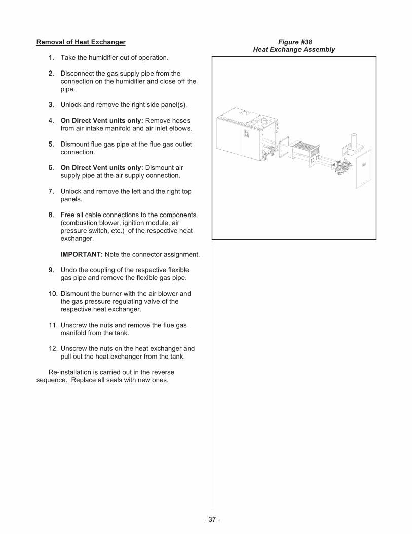
Removal of Heat Exchanger
1.1. Take the humidifier out of operation.
2.2. Disconnect the gas supply pipe from theconnection on the humidifier and close off thepipe.
3.3. Unlock and remove the right side panel(s).
4.4. On Direct Vent units only: Remove hosesfrom air intake manifold and air inlet elbows.
5.5. Dismount flue gas pipe at the flue gas outletconnection.
6.6. On Direct Vent units only: Dismount airsupply pipe at the air supply connection.
7.7. Unlock and remove the left and the right toppanels.
8.8. Free all cable connections to the components(combustion blower, ignition module, airpressure switch, etc.) of the respective heatexchanger.
IMPORTANT: Note the connector assignment.
9.9. Undo the coupling of the respective flexiblegas pipe and remove the flexible gas pipe.
10.10. Dismount the burner with the air blower andthe gas pressure regulating valve of therespective heat exchanger.
11. Unscrew the nuts and remove the flue gasmanifold from the tank.
12. Unscrew the nuts on the heat exchanger andpull out the heat exchanger from the tank.
Re-installation is carried out in the reversesequence. Replace all seals with new ones.
- 37 -
Figure #38Heat Exchange Assembly

- 38 -
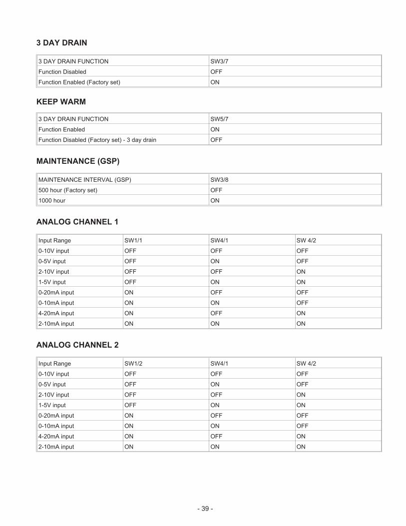
3 DAY DRAIN
3 DAY DRAIN FUNCTION SW3/7
Function Disabled OFF
Function Enabled (Factory set) ON
KEEP WARM
3 DAY DRAIN FUNCTION SW5/7
Function Enabled ON
Function Disabled (Factory set) - 3 day drain OFF
MAINTENANCE (GSP)
MAINTENANCE INTERVAL (GSP) SW3/8
500 hour (Factory set) OFF
1000 hour ON
ANALOG CHANNEL 1
Input Range SW1/1 SW4/1 SW 4/2
0-10V input OFF OFF OFF
0-5V input OFF ON OFF
2-10V input OFF OFF ON
1-5V input OFF ON ON
0-20mA input ON OFF OFF
0-10mA input ON ON OFF
4-20mA input ON OFF ON
2-10mA input ON ON ON
ANALOG CHANNEL 2
Input Range SW1/2 SW4/1 SW 4/2
0-10V input OFF OFF OFF
0-5V input OFF ON OFF
2-10V input OFF OFF ON
1-5V input OFF ON ON
0-20mA input ON OFF OFF
0-10mA input ON ON OFF
4-20mA input ON OFF ON
2-10mA input ON ON ON
- 39 -
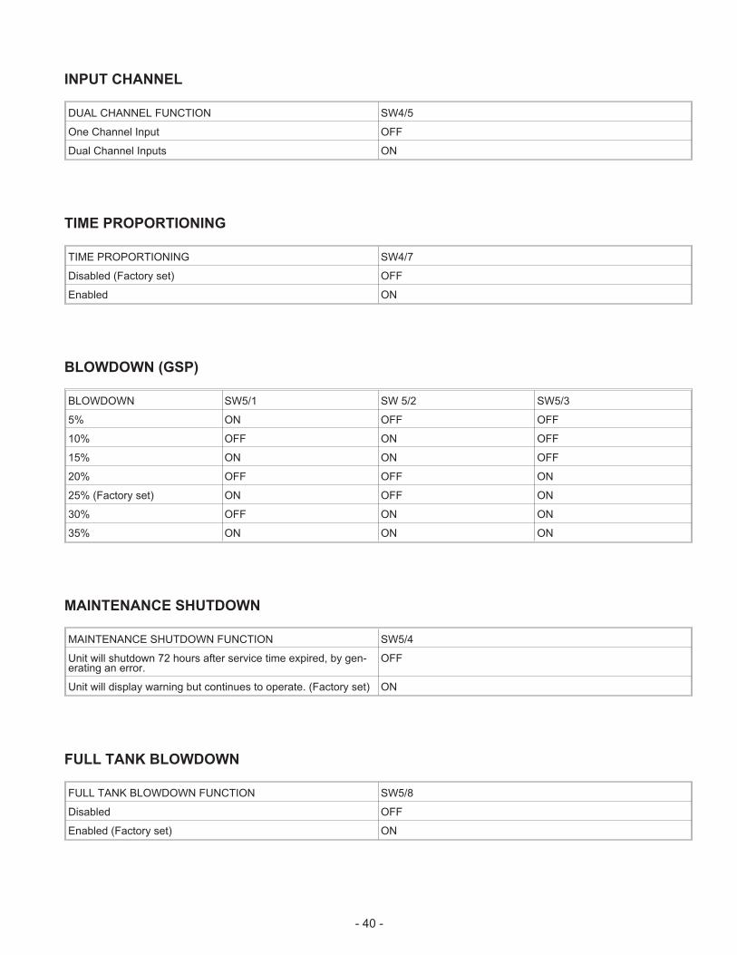
INPUT CHANNEL
DUAL CHANNEL FUNCTION SW4/5
One Channel Input OFF
Dual Channel Inputs ON
TIME PROPORTIONING
TIME PROPORTIONING SW4/7
Disabled (Factory set) OFF
Enabled ON
BLOWDOWN (GSP)
BLOWDOWN SW5/1 SW 5/2 SW5/3
5% ON OFF OFF
10% OFF ON OFF
15% ON ON OFF
20% OFF OFF ON
25% (Factory set) ON OFF ON
30% OFF ON ON
35% ON ON ON
MAINTENANCE SHUTDOWN
MAINTENANCE SHUTDOWN FUNCTION SW5/4
Unit will shutdown 72 hours after service time expired, by gen-erating an error.
OFF
Unit will display warning but continues to operate. (Factory set) ON
FULL TANK BLOWDOWN
FULL TANK BLOWDOWN FUNCTION SW5/8
Disabled OFF
Enabled (Factory set) ON
- 40 -
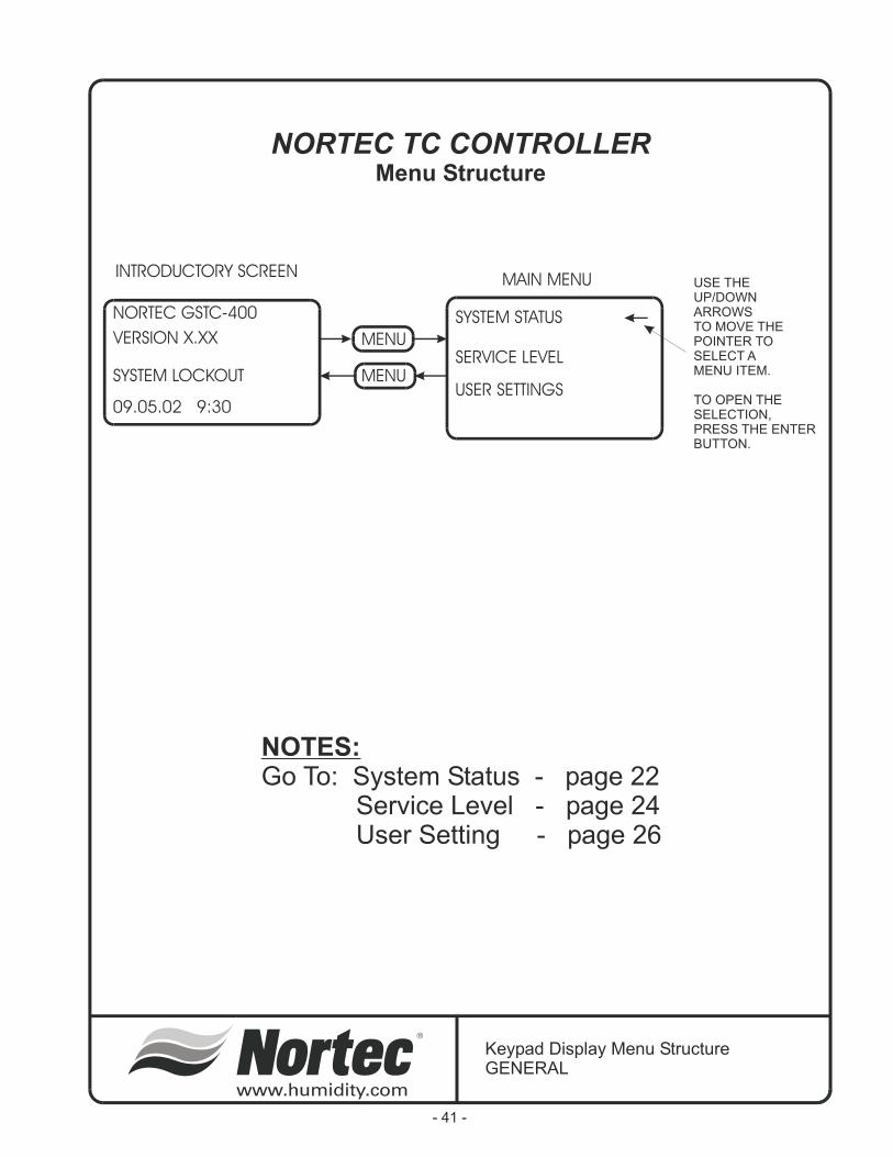
NORTEC GSTC-400
VERSION X.XX
SYSTEM LOCKOUT
09.05.02 9:30
SYSTEM STATUS
USER SETTINGS
SERVICE LEVELMENU
MENU
USE THEUP/DOWNARROWSTO MOVE THEPOINTER TOSELECT AMENU ITEM.
TO OPEN THESELECTION,PRESS THE ENTERBUTTON.
INTRODUCTORY SCREENMAIN MENU
Keypad Display Menu StructureGENERAL
NORTEC TC CONTROLLERMenu Structure
NOTES:
Go To: System Status - page 22Service Level - page 24User Setting - page 26
- 41 -

MENU
MENU
ENTER
MENU
MAIN MENU
SYSTEM STATUS
USER SETTINGS
STATUS: LOCKOUT
DEMAND CHANNEL 1 0%
DEMAND CHANNEL 2 0%
CAPACITY LIMIT 0%
1
2
SYSTEM DEMAND XXX%
BURNERS ACTIVE X/X
OUTPUT/BURNER XXXLB
TOTAL OUTPUT XXXLB
1
2
3
WATER LEVEL: X
FILL VALVE ON
DRAIN VALVE OFF
DRAIN COOLING: SMART
1
4
2
3
1. DISPLAY TOGGLES BETWEENLOCKOUT, ACTIVE, AND STANDBY,DEPENDING ON SYSTEM DEMAND
2. ONLY VIEWED IF UNITIS CONFIGURED FORDUAL CHANNEL.
1. DISPLAY WILL SHOW NUMBEROF BURNERS ANDDISPLAYS THE NUMBER OFACTIVE BURNERS.
2. DISPLAYS THE OUTPUT PERBURNER IN POUNDS PER HOUROR KG/HR.
3. DISPLAY OF TOTAL SYSTEMOUTPUT IN LBS/HR [KG/HR]
1. DEPENDING ON WATER LEVEL,WILL DISPLAY 0 - 5.
2. TOGGLES BETWEEN ON, OFF,AND PULSED.
3. TOGGLES BETWEEN ON AND OFF
4. DISPLAYS USER SETTING, ON, OFF,OR SMART
SYSTEM STATUS2
Keypad Display Menu StructureSystem Status 1 of 2
SYSTEM STATUS 1 of 2
- 42 -
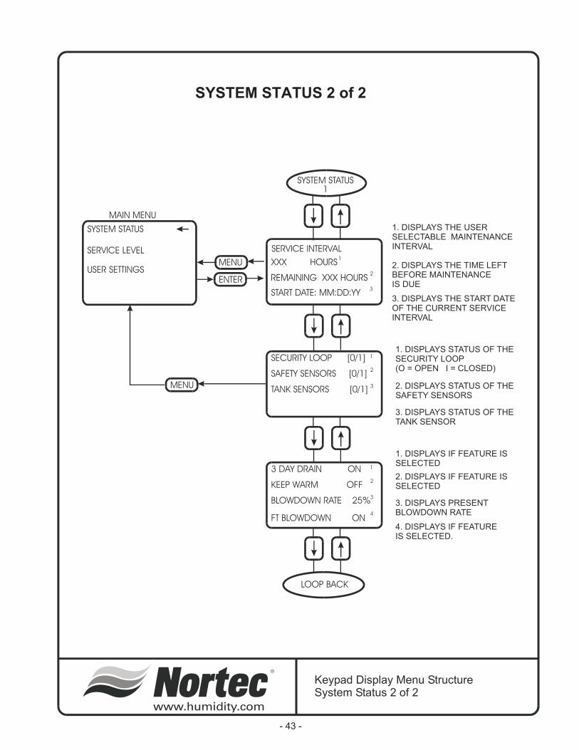
MENU
SERVICE INTERVAL
SECURITY LOOP [0/1]
3 DAY DRAIN ON
SAFETY SENSORS [0/1]
KEEP WARM OFF
TANK SENSORS [0/1]
BLOWDOWN RATE 25%
FT BLOWDOWN ON
XXX HOURS
START DATE: MM:DD:YY
REMAINING XXX HOURS
1
1
1
3
3
4
2
2
2
3
1. DISPLAYS THE USERSELECTABLE MAINTENANCEINTERVAL
1. DISPLAYS STATUS OF THESECURITY LOOP(O = OPEN I = CLOSED)
1. DISPLAYS IF FEATURE ISSELECTED
2. DISPLAYS STATUS OF THESAFETY SENSORS
2. DISPLAYS IF FEATURE ISSELECTED
3. DISPLAYS STATUS OF THETANK SENSOR
3. DISPLAYS PRESENTBLOWDOWN RATE
4. DISPLAYS IF FEATUREIS SELECTED.
3. DISPLAYS THE START DATEOF THE CURRENT SERVICEINTERVAL
2. DISPLAYS THE TIME LEFTBEFORE MAINTENANCEIS DUE
LOOP BACK
ENTER
MENU
MAIN MENU
SYSTEM STATUS
USER SETTINGS
SERVICE LEVEL
SYSTEM STATUS1
Keypad Display Menu StructureSystem Status 2 of 2
SYSTEM STATUS 2 of 2
- 43 -
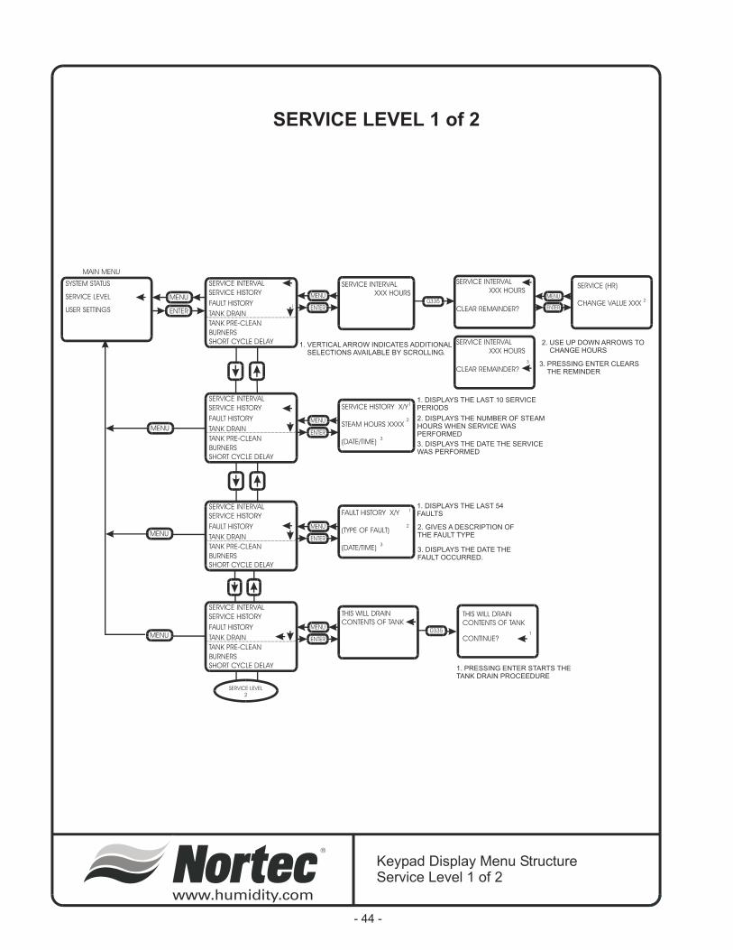
ENTER
MENU
MENU
MENU
MENU
MAIN MENU
SYSTEM STATUS
SERVICE LEVEL
USER SETTINGS
SERVICE INTERVAL
XXX HOURS
SERVICE HISTORY X/Y
STEAM HOURS XXXX
(DATE/TIME)
FAULT HISTORY X/Y
(TYPE OF FAULT)
(DATE/TIME)
THIS WILL DRAIN
CONTENTS OF TANKTHIS WILL DRAIN
CONTENTS OF TANK
CONTINUE?
SERVICE INTERVAL
XXX HOURS
SERVICE INTERVAL
XXX HOURS
CLEAR REMAINDER?
CLEAR REMAINDER?
SERVICE (HR)
CHANGE VALUE XXX
SERVICE INTERVAL
SERVICE HISTORY
FAULT HISTORY
TANK DRAIN
TANK PRE-CLEAN
SHORT CYCLE DELAY
BURNERS
1
SERVICE INTERVAL
SERVICE INTERVAL
SERVICE INTERVAL
SERVICE HISTORY
SERVICE HISTORY
SERVICE HISTORY
FAULT HISTORY
FAULT HISTORY
FAULT HISTORY
TANK DRAIN
TANK DRAIN
TANK DRAIN
TANK PRE-CLEAN
TANK PRE-CLEAN
TANK PRE-CLEAN
SHORT CYCLE DELAY
SHORT CYCLE DELAY
SHORT CYCLE DELAY
BURNERS
BURNERS
BURNERS
2
3
1. VERTICAL ARROW INDICATES ADDITIONALSELECTIONS AVAILABLE BY SCROLLING.
2. USE UP DOWN ARROWS TOCHANGE HOURS
3. PRESSING ENTER CLEARSTHE REMINDER
1
1
1
2
2
3
3
1. DISPLAYS THE LAST 10 SERVICEPERIODS
1. DISPLAYS THE LAST 54FAULTS
1. PRESSING ENTER STARTS THETANK DRAIN PROCEEDURE
2. DISPLAYS THE NUMBER OF STEAMHOURS WHEN SERVICE WASPERFORMED
2. GIVES A DESCRIPTION OFTHE FAULT TYPE
3. DISPLAYS THE DATE THE SERVICEWAS PERFORMED
3. DISPLAYS THE DATE THEFAULT OCCURRED.
SERVICE LEVEL
2
Keypad Display Menu StructureService Level 1 of 2
SERVICE LEVEL 1 of 2
- 44 -
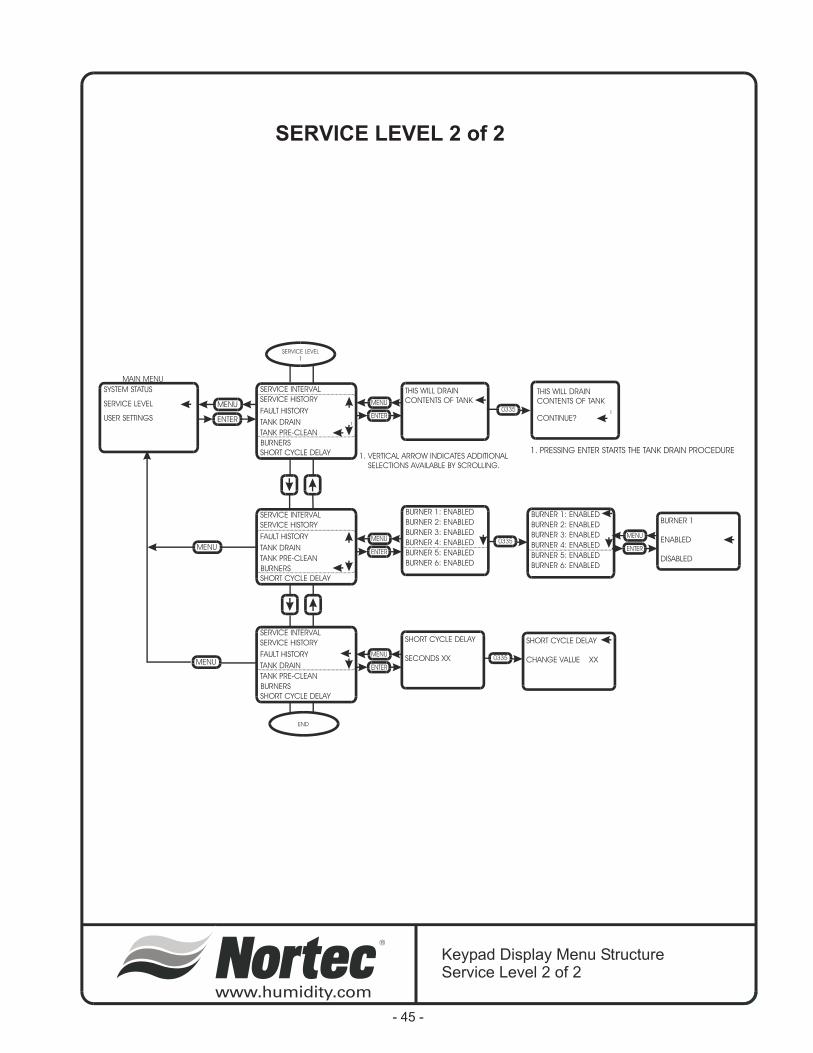
ENTER
MENU
MENU
MENU
MAIN MENU
SYSTEM STATUS
SERVICE LEVEL
USER SETTINGS
SHORT CYCLE DELAY
SECONDS XX
SHORT CYCLE DELAY
CHANGE VALUE XX
BURNER 1
ENABLED
DISABLED
THIS WILL DRAIN
CONTENTS OF TANKTHIS WILL DRAIN
CONTENTS OF TANK
CONTINUE?
SERVICE INTERVAL
SERVICE HISTORY
FAULT HISTORY
TANK DRAIN
TANK PRE-CLEAN
SHORT CYCLE DELAY
BURNERS
1
SERVICE INTERVAL BURNER 1: ENABLED BURNER 1: ENABLEDBURNER 2: ENABLED BURNER 2: ENABLEDBURNER 3: ENABLED BURNER 3: ENABLEDBURNER 4: ENABLED BURNER 4: ENABLEDBURNER 5: ENABLED BURNER 5: ENABLEDBURNER 6: ENABLED BURNER 6: ENABLED
SERVICE INTERVAL
SERVICE HISTORY
SERVICE HISTORY
FAULT HISTORY
FAULT HISTORY
TANK DRAIN
TANK DRAIN
TANK PRE-CLEAN
TANK PRE-CLEAN
SHORT CYCLE DELAY
SHORT CYCLE DELAY
BURNERS
BURNERS
1. VERTICAL ARROW INDICATES ADDITIONAL
SELECTIONS AVAILABLE BY SCROLLING.
1
1. PRESSING ENTER STARTS THE TANK DRAIN PROCEDURE
END
SERVICE LEVEL
1
Keypad Display Menu StructureService Level 2 of 2
SERVICE LEVEL 2 of 2
- 45 -
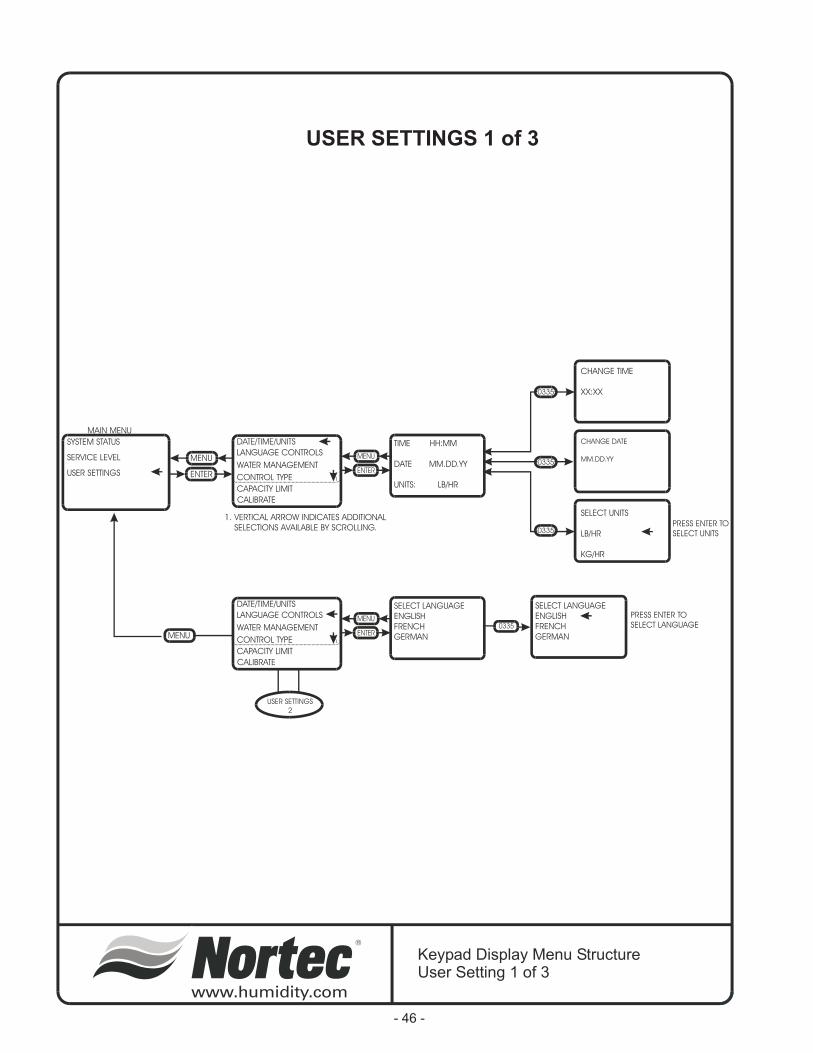
ENTER
MENU
MENU
MAIN MENU
SYSTEM STATUS
SERVICE LEVEL
USER SETTINGS
TIME HH:MM
DATE MM.DD.YY
UNITS: LB/HR
DATE/TIME/UNITS
LANGUAGE CONTROLS
WATER MANAGEMENT
CONTROL TYPE
CAPACITY LIMIT
CALIBRATE
1
1. VERTICAL ARROW INDICATES ADDITIONAL
SELECTIONS AVAILABLE BY SCROLLING.
SELECT LANGUAGE
ENGLISH
FRENCH
GERMAN
SELECT LANGUAGE
ENGLISH
FRENCH
GERMAN
DATE/TIME/UNITS
LANGUAGE CONTROLS
WATER MANAGEMENT
CONTROL TYPE
CAPACITY LIMIT
CALIBRATE
1
SELECT UNITS
LB/HR
KG/HR
CHANGE DATE
MM.DD.YY
CHANGE TIME
XX:XX
0335
0335
0335
PRESS ENTER TO
SELECT UNITS
PRESS ENTER TO
SELECT LANGUAGE
USER SETTINGS
2
Keypad Display Menu StructureUser Setting 1 of 3
USER SETTINGS 1 of 3
- 46 -

FTBD HOURS
CHANGE HOURS? XXX
FTBD HOUR
CHANGE HOUR? XX
FILL CORRCTN
CHANGE VALUE XXX%
FLOAT CHECK
CHANGE VALUE HH:MM
DRAIN CORRCTN
CHANGE VALUE XXX%
DRAIN COOL
ON
OFF
SMART
BLOWDOWN RATE
CHANGE VALUE XX%
STEAM OUTPUT
ENTER
MENU
MAIN MENU
SYSTEM STATUS
SERVICE LEVEL
USER SETTINGS
DATE/TIME/UNITS FTBD HOURS XXX
FTBD HOUR XX
BLOWDOWN RATE XX%
FLOAT CHECK HH:MM
FILL CORRCTN XX%
DRAIN CORRCTN XX%
DRAIN COOL: SMART
LANGUAGE CONTROLS
WATER MANAGEMENT
CONTROL TYPE
CAPACITY LIMIT
CALIBRATE
1
1. VERTICAL ARROW INDICATES
ADDITIONAL SELECTIONS
AVAILABLE BY SCROLLING.
USER SETTINGS
PAGE 1
USER SETTINGS
3
0335
0335
0335
0335
0335
0335
0335
Keypad Display Menu StructureUser Setting 2 of 3
USER SETTINGS 2 of 3
- 47 -

MENU
MENU
SET MAXIMUM
CAPACITY XXX%SET MAXIMUM
CAPACITY XXX%
CALIBRATE
SIGNAL?
CALIBRATE
SIGNAL
CALIBRATE 4957
DATE/TIME/UNITS
DATE/TIME/UNITS
LANGUAGE CONTROLS
LANGUAGE CONTROLS
WATER MANAGEMENT
WATER MANAGEMENT
CONTROL TYPE
CONTROL TYPE
CAPACITY LIMIT
CAPACITY LIMIT
CALIBRATE
CALIBRATE
USEUP/DOWNARROWSTO SETMAXIMUMCAPACITY
PRESSENTER TOCALIBRATESIGNAL
END
ENTER
MENU
MAIN MENU
SYSTEM STATUS
SERVICE LEVEL
USER SETTINGS
CONTROL TYPE
CONTROL INPUT
TRANSDUCER INPUT
CONTROL TYPE
CONTROL INPUT
TRANSDUCER INPUT
DATE/TIME/UNITS
LANGUAGE CONTROLS
WATER MANAGEMENT
CONTROL TYPE
CAPACITY LIMIT
CALIBRATE
1
1. VERTICAL ARROW INDICATES ADDITIONAL
SELECTIONS AVAILABLE BY SCROLLING.
0335
PRESSENTER TOSELECTCONTROLTYPE
USER SETTINGS
2
Keypad Display Menu StructureUser Setting 3 of 3
USER SETTINGS 3 of 3
- 48 -
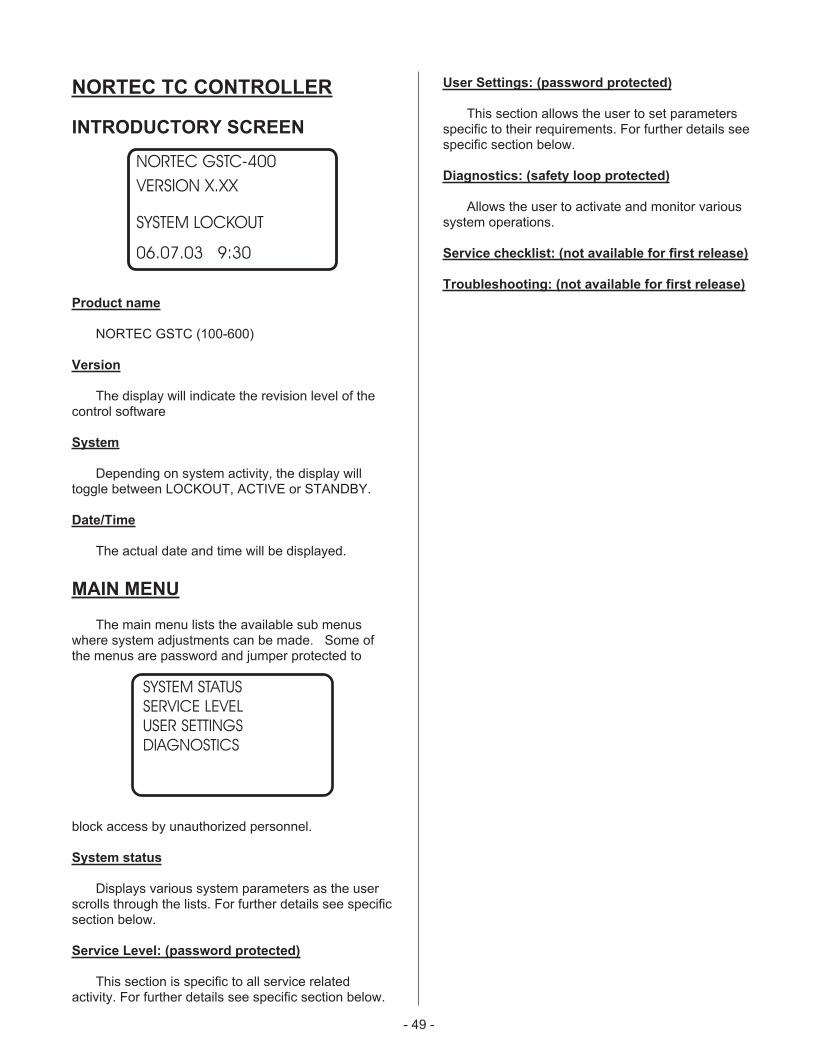
- 49 -
NORTEC TC CONTROLLER
INTRODUCTORY SCREEN
Product name
NORTEC GSTC (100-600)
Version
The display will indicate the revision level of thecontrol software
System
Depending on system activity, the display willtoggle between LOCKOUT, ACTIVE or STANDBY.
Date/Time
The actual date and time will be displayed.
MAIN MENU
The main menu lists the available sub menuswhere system adjustments can be made. Some ofthe menus are password and jumper protected to
block access by unauthorized personnel.
System status
Displays various system parameters as the userscrolls through the lists. For further details see specificsection below.
Service Level: (password protected)
This section is specific to all service relatedactivity. For further details see specific section below.
User Settings: (password protected)
This section allows the user to set parametersspecific to their requirements. For further details seespecific section below.
Diagnostics: (safety loop protected)
Allows the user to activate and monitor varioussystem operations.
Service checklist: (not available for first release)
Troubleshooting: (not available for first release)
NORTEC GSTC-400
VERSION X.XX
SYSTEM LOCKOUT
06.07.03 9:30
SYSTEM STATUS
SERVICE LEVEL
USER SETTINGS
DIAGNOSTICS
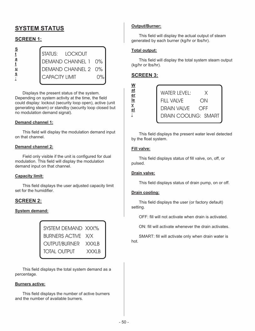
- 50 -
SYSTEM STATUS
SCREEN 1:
S
t
a
t
u
s
:
Displays the present status of the system.Depending on system activity at the time, the fieldcould display: lockout (security loop open), active (unitgenerating steam) or standby (security loop closed butno modulation demand signal).
Demand channel 1:
This field will display the modulation demand inputon that channel.
Demand channel 2:
Field only visible if the unit is configured for dualmodulation. This field will display the modulationdemand input on that channel.
Capacity limit:
This field displays the user adjusted capacity limitset for the humidifier.
SCREEN 2:
System demand:
This field displays the total system demand as apercentage.
Burners active:
This field displays the number of active burnersand the number of available burners.
Output/Burner:
This field will display the actual output of steamgenerated by each burner (kg/hr or lbs/hr).
Total output:
This field will display the total system steam output(kg/hr or lbs/hr).
SCREEN 3:
W
at
er
le
v
el
:
This field displays the present water level detectedby the float system.
Fill valve:
This field displays status of fill valve, on, off, orpulsed.
Drain valve:
This field displays status of drain pump, on or off.
Drain cooling:
This field displays the user (or factory default)setting.
OFF: fill will not activate when drain is activated.
ON: fill will activate whenever the drain activates.
SMART: fill will activate only when drain water ishot.
STATUS: LOCKOUT
DEMAND CHANNEL 1 0%
DEMAND CHANNEL 2 0%
CAPACITY LIMIT 0%
SYSTEM DEMAND XXX%
BURNERS ACTIVE X/X
OUTPUT/BURNER XXXLB
TOTAL OUTPUT XXXLB
WATER LEVEL: X
FILL VALVE ON
DRAIN VALVE OFF
DRAIN COOLING: SMART
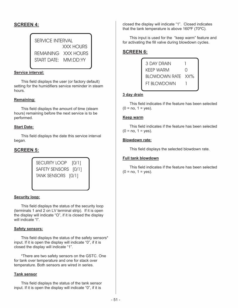
SCREEN 4:
Service interval:
This field displays the user (or factory default)setting for the humidifiers service reminder in steamhours.
Remaining:
This field displays the amount of time (steamhours) remaining before the next service is to beperformed.
Start Date:
This field displays the date this service intervalbegan.
SCREEN 5:
Security loop:
This field displays the status of the security loop(terminals 1 and 2 on LV terminal strip). If it is openthe display will indicate “O”, if it is closed the displaywill indicate “I”.
Safety sensors:
This field displays the status of the safety sensors*input. If it is open the display will indicate “0”, if it isclosed the display will indicate “1”.
*There are two safety sensors on the GSTC. Onefor tank over temperature and one for stack overtemperature. Both sensors are wired in series.
Tank sensor
This field displays the status of the tank sensorinput. If it is open the display will indicate “0”, if it is
closed the display will indicate “1”. Closed indicatesthat the tank temperature is above 160ºF (70ºC).
This input is used for the “keep warm” feature andfor activating the fill valve during blowdown cycles.
SCREEN 6:
3 day drain
This field indicates if the feature has been selected(0 = no, 1 = yes).
Keep warm
This field indicates if the feature has been selected(0 = no, 1 = yes).
Blowdown rate:
This field displays the selected blowdown rate.
Full tank blowdown
This field indicates if the feature has been selected(0 = no, 1 = yes).
- 51 -
SECURITY LOOP [0/1]
SAFETY SENSORS [0/1]
TANK SENSORS [0/1]
3 DAY DRAIN 1
KEEP WARM 0
BLOWDOWN RATE XX%
FT BLOWDOWN 1
SERVICE INTERVAL
XXX HOURS
START DATE: MM:DD:YY
REMAINING XXX HOURS

- 52 -
SERVICE LEVEL
The service level area is where service related tasks are performed. Below is a description of each field and whatcan be performed in them. When a parameter requires a change, press the two arrow keys and enter the password(0335). As long as you remain in this section, you will not need to enter the password more than once.
Service interval
In this area the customer can set a service interval for humidifier MAINTENANCE.
MAINTENANCE TIMEXXX HOURS
This field displays the user selected MAINTENANCE time. To change the time selected enter the user code andadjust the time in SET MAINT. TIME (0-3000 hours, 0 = disabled).
MAINTENANCE DUEXXX HOURS
This field displays the time remaining until the next service interval. To reset the MAINTENANCE due time, enterthe user code and select CLEAR REMINDER?
Service history
In this area the customer can view the history of service maintenance performed on the humidifier.
SERVICE HISTORY X/Y
The service history stores the last 10 service periods.
X = service occurrence, where 1 is the most recent.
SERVICE INTERVAL
SERVICE HISTORY
FAULT HISTORY
TANK DRAIN
TANK PRE-CLEAN
BURNERS
SHORT CYCLE DELAY
MAINTENANCE TIME
XXX HOURS
MAINTENANCE DUE
XXX HOURS
SERVICE INTERVAL
XXX HOURS
CLEAR REMAINDER?
SERVICE INTERVAL
SERVICE HISTORY
FAULT HISTORY
TANK DRAIN
TANK PRE-CLEAN
SHORT CYCLE DELAY
BURNERS
1
SERVICE HISTORY X/Y
STEAM HOURS XXXX
(DATE/TIME)
SERVICE INTERVAL
SERVICE HISTORY
FAULT HISTORY
TANK DRAIN
TANK PRE-CLEAN
SHORT CYCLE DELAY
BURNERS
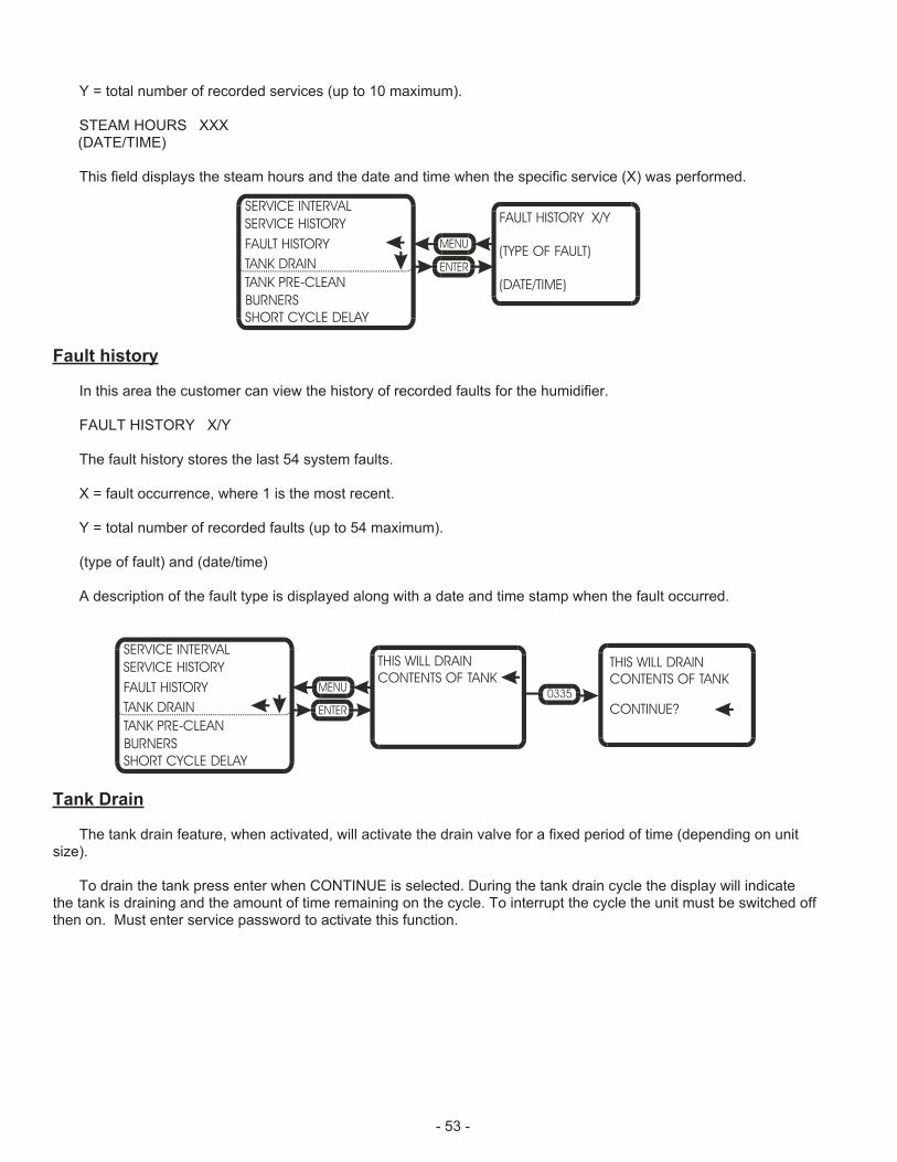
Y = total number of recorded services (up to 10 maximum).
STEAM HOURS XXX(DATE/TIME)
This field displays the steam hours and the date and time when the specific service (X) was performed.
Fault history
In this area the customer can view the history of recorded faults for the humidifier.
FAULT HISTORY X/Y
The fault history stores the last 54 system faults.
X = fault occurrence, where 1 is the most recent.
Y = total number of recorded faults (up to 54 maximum).
(type of fault) and (date/time)
A description of the fault type is displayed along with a date and time stamp when the fault occurred.
Tank Drain
The tank drain feature, when activated, will activate the drain valve for a fixed period of time (depending on unitsize).
To drain the tank press enter when CONTINUE is selected. During the tank drain cycle the display will indicatethe tank is draining and the amount of time remaining on the cycle. To interrupt the cycle the unit must be switched offthen on. Must enter service password to activate this function.
FAULT HISTORY X/Y
(TYPE OF FAULT)
(DATE/TIME)
SERVICE INTERVAL
SERVICE HISTORY
FAULT HISTORY
TANK DRAIN
TANK PRE-CLEAN
SHORT CYCLE DELAY
BURNERS
THIS WILL DRAIN
CONTENTS OF TANKTHIS WILL DRAIN
CONTENTS OF TANK
CONTINUE?
SERVICE INTERVAL
SERVICE HISTORY
FAULT HISTORY
TANK DRAIN
TANK PRE-CLEAN
SHORT CYCLE DELAY
BURNERS
- 53 -
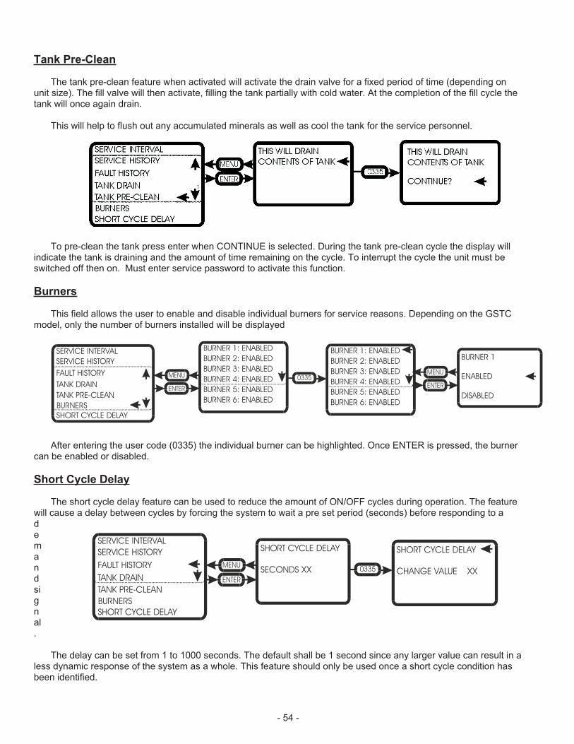
Tank Pre-Clean
The tank pre-clean feature when activated will activate the drain valve for a fixed period of time (depending onunit size). The fill valve will then activate, filling the tank partially with cold water. At the completion of the fill cycle thetank will once again drain.
This will help to flush out any accumulated minerals as well as cool the tank for the service personnel.
To pre-clean the tank press enter when CONTINUE is selected. During the tank pre-clean cycle the display willindicate the tank is draining and the amount of time remaining on the cycle. To interrupt the cycle the unit must beswitched off then on. Must enter service password to activate this function.
Burners
This field allows the user to enable and disable individual burners for service reasons. Depending on the GSTCmodel, only the number of burners installed will be displayed
After entering the user code (0335) the individual burner can be highlighted. Once ENTER is pressed, the burnercan be enabled or disabled.
Short Cycle Delay
The short cycle delay feature can be used to reduce the amount of ON/OFF cycles during operation. The featurewill cause a delay between cycles by forcing the system to wait a pre set period (seconds) before responding to ademandsignal.
The delay can be set from 1 to 1000 seconds. The default shall be 1 second since any larger value can result in aless dynamic response of the system as a whole. This feature should only be used once a short cycle condition hasbeen identified.
BURNER 1
ENABLED
DISABLED
SERVICE INTERVAL BURNER 1: ENABLED BURNER 1: ENABLEDBURNER 2: ENABLED BURNER 2: ENABLEDBURNER 3: ENABLED BURNER 3: ENABLEDBURNER 4: ENABLED BURNER 4: ENABLEDBURNER 5: ENABLED BURNER 5: ENABLEDBURNER 6: ENABLED BURNER 6: ENABLED
SERVICE HISTORY
FAULT HISTORY
TANK DRAIN
TANK PRE-CLEAN
SHORT CYCLE DELAY
BURNERS
SHORT CYCLE DELAY
SECONDS XX
SHORT CYCLE DELAY
CHANGE VALUE XX
SERVICE INTERVAL
SERVICE HISTORY
FAULT HISTORY
TANK DRAIN
TANK PRE-CLEAN
SHORT CYCLE DELAY
BURNERS
- 54 -
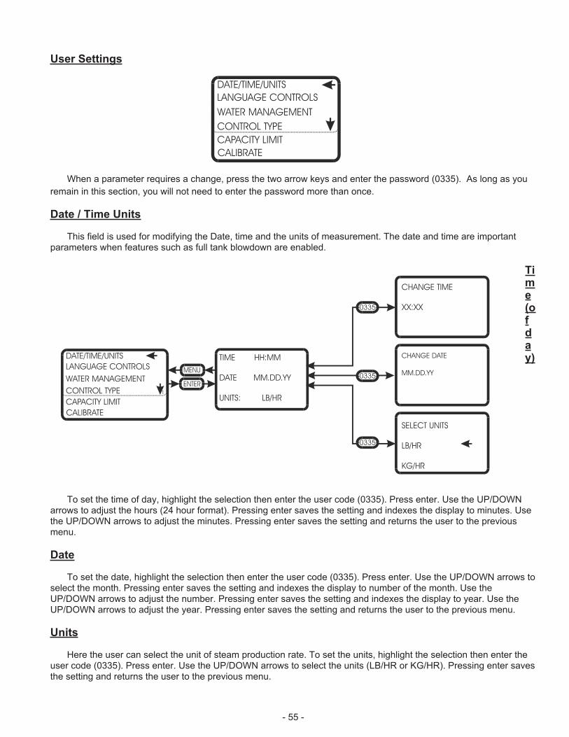
- 55 -
User Settings
When a parameter requires a change, press the two arrow keys and enter the password (0335). As long as you
remain in this section, you will not need to enter the password more than once.
Date / Time Units
This field is used for modifying the Date, time and the units of measurement. The date and time are importantparameters when features such as full tank blowdown are enabled.
Ti
m
e
(o
f
d
a
y)
To set the time of day, highlight the selection then enter the user code (0335). Press enter. Use the UP/DOWNarrows to adjust the hours (24 hour format). Pressing enter saves the setting and indexes the display to minutes. Usethe UP/DOWN arrows to adjust the minutes. Pressing enter saves the setting and returns the user to the previousmenu.
Date
To set the date, highlight the selection then enter the user code (0335). Press enter. Use the UP/DOWN arrows toselect the month. Pressing enter saves the setting and indexes the display to number of the month. Use theUP/DOWN arrows to adjust the number. Pressing enter saves the setting and indexes the display to year. Use theUP/DOWN arrows to adjust the year. Pressing enter saves the setting and returns the user to the previous menu.
Units
Here the user can select the unit of steam production rate. To set the units, highlight the selection then enter theuser code (0335). Press enter. Use the UP/DOWN arrows to select the units (LB/HR or KG/HR). Pressing enter savesthe setting and returns the user to the previous menu.
DATE/TIME/UNITS
LANGUAGE CONTROLS
WATER MANAGEMENT
CONTROL TYPE
CAPACITY LIMIT
CALIBRATE
TIME HH:MM
DATE MM.DD.YY
UNITS: LB/HR
DATE/TIME/UNITS
LANGUAGE CONTROLS
WATER MANAGEMENT
CONTROL TYPE
CAPACITY LIMIT
CALIBRATE
1
SELECT UNITS
LB/HR
KG/HR
CHANGE DATE
MM.DD.YY
CHANGE TIME
XX:XX
0335
0335
0335

Language Controls
This field allows the user to select the menu language of choice (English, French, German)
Here the user can select the language of choice for the menu displays. To set the language, highlight theselection then enter the user code (0335). Press enter. Use the UP/DOWN arrows to select the choice (English,French, German). Pressing enter saves the setting and returns the user to the previous menu.
NOTE: ONLY ENGLISH AVAILABLE AS OF 05/03
Water Management
This section allows the user to set time based parameters and adjust water control parameters.
FTBD Hours
This section allows the user to set the frequency of full tank blowdowns (FTBD). FTBD’s drains and re-fills theentire contents of the humidifier after a preset accumulated operating time. Run time is measured in steam hours(weighted run time hours), and can be adjusted from 0 hours (feature off) to 400 hours in 25 hour increments.
Once the FTBD time has expired, the controller will wait until the FTBD hour to initiate the cycle. This preventsrandom drains at times when they would be inconvenient.
SELECT LANGUAGE
ENGLISH
FRENCH
GERMAN
SELECT LANGUAGE
ENGLISH
FRENCH
GERMAN
DATE/TIME/UNITS
LANGUAGE CONTROLS
WATER MANAGEMENT
CONTROL TYPE
CAPACITY LIMIT
CALIBRATE
FTBD HOURS
CHANGE HOURS? XXX
DATE/TIME/UNITS FTBD HOURS XXX
FTBD HOUR XX
BLOWDOWN RATE XX%
FLOAT CHECK HH:MM
FILL CORRCTN XX%
DRAIN CORRCTN XX%
DRAIN COOL: SMART
LANGUAGE CONTROLS
WATER MANAGEMENT
CONTROL TYPE
CAPACITY LIMIT
CALIBRATE
0335
FTBD HOUR
CHANGE HOUR? XXX
DATE/TIME/UNITS FTBD HOURS XXX
FTBD HOUR XX
BLOWDOWN RATE XX%
FLOAT CHECK HH:MM
FILL CORRCTN XX%
DRAIN CORRCTN XX%
DRAIN COOL: ON
LANGUAGE CONTROLS
WATER MANAGEMENT
CONTROL TYPE
CAPACITY LIMIT
CALIBRATE
0335
- 56 -
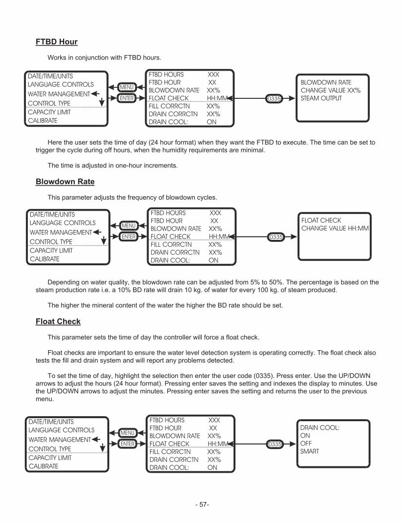
FTBD Hour
Works in conjunction with FTBD hours.
Here the user sets the time of day (24 hour format) when they want the FTBD to execute. The time can be set totrigger the cycle during off hours, when the humidity requirements are minimal.
The time is adjusted in one-hour increments.
Blowdown Rate
This parameter adjusts the frequency of blowdown cycles.
Depending on water quality, the blowdown rate can be adjusted from 5% to 50%. The percentage is based on thesteam production rate i.e. a 10% BD rate will drain 10 kg. of water for every 100 kg. of steam produced.
The higher the mineral content of the water the higher the BD rate should be set.
Float Check
This parameter sets the time of day the controller will force a float check.
Float checks are important to ensure the water level detection system is operating correctly. The float check alsotests the fill and drain system and will report any problems detected.
To set the time of day, highlight the selection then enter the user code (0335). Press enter. Use the UP/DOWNarrows to adjust the hours (24 hour format). Pressing enter saves the setting and indexes the display to minutes. Usethe UP/DOWN arrows to adjust the minutes. Pressing enter saves the setting and returns the user to the previousmenu.
BLOWDOWN RATE
CHANGE VALUE XX%
STEAM OUTPUT
DATE/TIME/UNITS FTBD HOURS XXX
FTBD HOUR XX
BLOWDOWN RATE XX%
FLOAT CHECK HH:MM
FILL CORRCTN XX%
DRAIN CORRCTN XX%
DRAIN COOL: ON
LANGUAGE CONTROLS
WATER MANAGEMENT
CONTROL TYPE
CAPACITY LIMIT
CALIBRATE
0335
FLOAT CHECK
CHANGE VALUE HH:MM
DATE/TIME/UNITS FTBD HOURS XXX
FTBD HOUR XX
BLOWDOWN RATE XX%
FLOAT CHECK HH:MM
FILL CORRCTN XX%
DRAIN CORRCTN XX%
DRAIN COOL: ON
LANGUAGE CONTROLS
WATER MANAGEMENT
CONTROL TYPE
CAPACITY LIMIT
CALIBRATE
0335
DRAIN COOL:
ON
OFF
SMART
DATE/TIME/UNITS FTBD HOURS XXX
FTBD HOUR XX
BLOWDOWN RATE XX%
FLOAT CHECK HH:MM
FILL CORRCTN XX%
DRAIN CORRCTN XX%
DRAIN COOL: ON
LANGUAGE CONTROLS
WATER MANAGEMENT
CONTROL TYPE
CAPACITY LIMIT
CALIBRATE
0335
- 57-
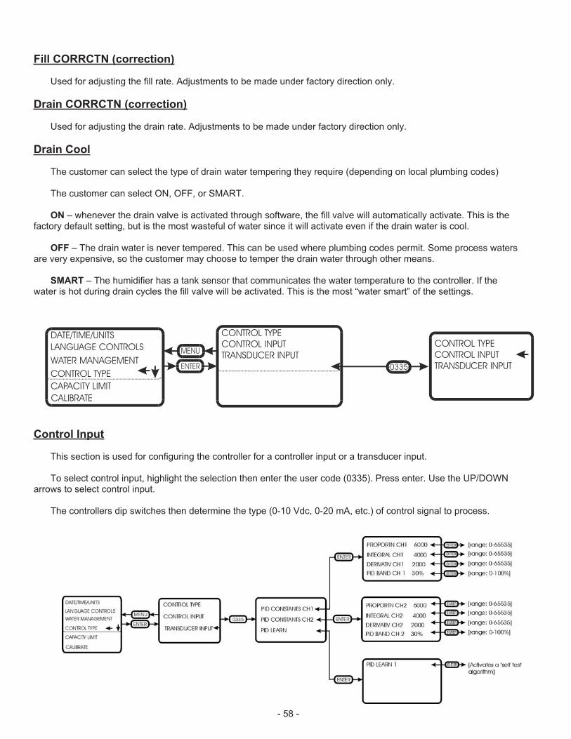
Fill CORRCTN (correction)
Used for adjusting the fill rate. Adjustments to be made under factory direction only.
Drain CORRCTN (correction)
Used for adjusting the drain rate. Adjustments to be made under factory direction only.
Drain Cool
The customer can select the type of drain water tempering they require (depending on local plumbing codes)
The customer can select ON, OFF, or SMART.
ON – whenever the drain valve is activated through software, the fill valve will automatically activate. This is thefactory default setting, but is the most wasteful of water since it will activate even if the drain water is cool.
OFF – The drain water is never tempered. This can be used where plumbing codes permit. Some process watersare very expensive, so the customer may choose to temper the drain water through other means.
SMART – The humidifier has a tank sensor that communicates the water temperature to the controller. If thewater is hot during drain cycles the fill valve will be activated. This is the most “water smart” of the settings.
Control Input
This section is used for configuring the controller for a controller input or a transducer input.
To select control input, highlight the selection then enter the user code (0335). Press enter. Use the UP/DOWNarrows to select control input.
The controllers dip switches then determine the type (0-10 Vdc, 0-20 mA, etc.) of control signal to process.
CONTROL TYPE
CONTROL INPUT
TRANSDUCER INPUT
DATE/TIME/UNITS CONTROL TYPE
CONTROL INPUT
TRANSDUCER INPUTLANGUAGE CONTROLS
WATER MANAGEMENT
CONTROL TYPE
CAPACITY LIMIT
CALIBRATE
0335
- 58 -
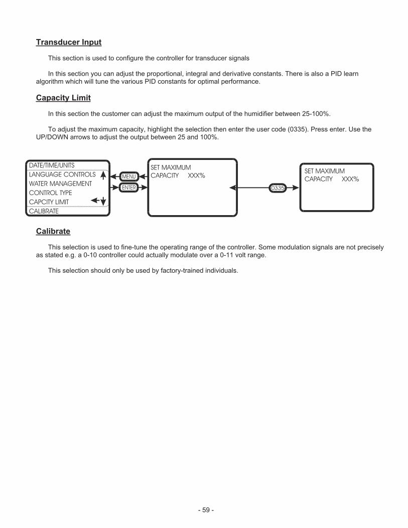
Transducer Input
This section is used to configure the controller for transducer signals
In this section you can adjust the proportional, integral and derivative constants. There is also a PID learnalgorithm which will tune the various PID constants for optimal performance.
Capacity Limit
In this section the customer can adjust the maximum output of the humidifier between 25-100%.
To adjust the maximum capacity, highlight the selection then enter the user code (0335). Press enter. Use theUP/DOWN arrows to adjust the output between 25 and 100%.
Calibrate
This selection is used to fine-tune the operating range of the controller. Some modulation signals are not preciselyas stated e.g. a 0-10 controller could actually modulate over a 0-11 volt range.
This selection should only be used by factory-trained individuals.
DATE/TIME/UNITS
LANGUAGE CONTROLS
WATER MANAGEMENT
CONTROL TYPE
CAPCITY LIMIT
CALIBRATE
SET MAXIMUM
CAPACITY XXX%
0335
SET MAXIMUM
CAPACITY XXX%
- 59 -
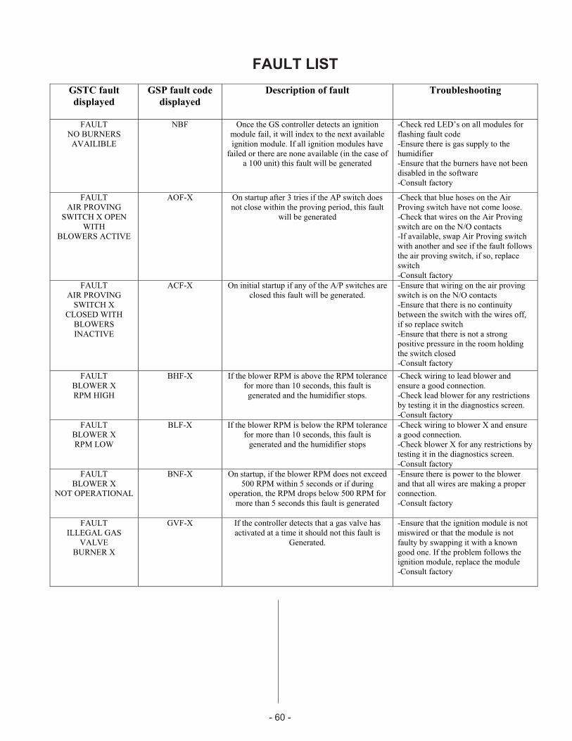
FAULT LIST
GSTC fault
displayed
GSP fault code
displayed
Description of fault Troubleshooting
FAULT
NO BURNERS
AVAILIBLE
NBF Once the GS controller detects an ignition
module fail, it will index to the next available
ignition module. If all ignition modules have
failed or there are none available (in the case of
a 100 unit) this fault will be generated
-Check red LED’s on all modules for
flashing fault code
-Ensure there is gas supply to the
humidifier
-Ensure that the burners have not been
disabled in the software
-Consult factory
FAULT
AIR PROVING
SWITCH X OPEN
WITH
BLOWERS ACTIVE
AOF-X On startup after 3 tries if the AP switch does
not close within the proving period, this fault
will be generated
-Check that blue hoses on the Air
Proving switch have not come loose.
-Check that wires on the Air Proving
switch are on the N/O contacts
-If available, swap Air Proving switch
with another and see if the fault follows
the air proving switch, if so, replace
switch
-Consult factory
FAULT
AIR PROVING
SWITCH X
CLOSED WITH
BLOWERS
INACTIVE
ACF-X On initial startup if any of the A/P switches are
closed this fault will be generated.
-Ensure that wiring on the air proving
switch is on the N/O contacts
-Ensure that there is no continuity
between the switch with the wires off,
if so replace switch
-Ensure that there is not a strong
positive pressure in the room holding
the switch closed
-Consult factory
FAULT
BLOWER X
RPM HIGH
BHF-X If the blower RPM is above the RPM tolerance
for more than 10 seconds, this fault is
generated and the humidifier stops.
-Check wiring to lead blower and
ensure a good connection.
-Check lead blower for any restrictions
by testing it in the diagnostics screen.
-Consult factory
FAULT
BLOWER X
RPM LOW
BLF-X If the blower RPM is below the RPM tolerance
for more than 10 seconds, this fault is
generated and the humidifier stops
-Check wiring to blower X and ensure
a good connection.
-Check blower X for any restrictions by
testing it in the diagnostics screen.
-Consult factory
FAULT
BLOWER X
NOT OPERATIONAL
BNF-X On startup, if the blower RPM does not exceed
500 RPM within 5 seconds or if during
operation, the RPM drops below 500 RPM for
more than 5 seconds this fault is generated
-Ensure there is power to the blower
and that all wires are making a proper
connection.
-Consult factory
FAULT
ILLEGAL GAS
VALVE
BURNER X
GVF-X If the controller detects that a gas valve has
activated at a time it should not this fault is
Generated.
-Ensure that the ignition module is not
miswired or that the module is not
faulty by swapping it with a known
good one. If the problem follows the
ignition module, replace the module
-Consult factory
- 60 -
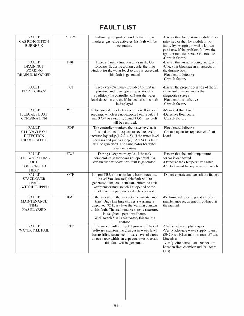
FAULT LIST
FAULT
GAS RE-IGNITION
BURNER X
GIF-X Following an ignition module fault if the
modules gas valve activates this fault will be
generated.
-Ensure that the ignition module is not
miswired or that the module is not
faulty by swapping it with a known
good one. If the problem follows the
ignition module, replace the module
-Consult factory
FAULT
DRAIN NOT
WORKING
DRAIN IS BLOCKED
DBF There are many time windows in the GS
software. If, during a drain cycle, the time
window for the water level to drop is exceeded,
this fault is generated
-Ensure that pump is being energized
-Check for blockage in all aspects of
the drain system
-Float board defective
-Consult factory
FAULT
FLOAT CHECK
FCF Once every 24 hours (provided the unit is
powered and in an operating or standby
condition) the controller will test the water
level detection circuit. If the test fails this fault
is displayed
-Ensure the proper operation of the fill
valve and drain valve via the
diagnostics screen
-Float board is defective
-Consult factory
FAULT
ILLEGAL FLOAT
COMBINATION
WLF If the controller detects two or more float level
readings, which are not expected (ex. Switch 1
and 3 ON or switch 1, 2, and 3 ON) this fault
will be recorded.
-Miswired float board
-Defective float board
-Consult factory
FAULT
FILL VAVLE ON
DETECTION
INCONSISTENT
FDF The controller monitors the water level as it
fills and drains. It expects to see the levels
increase logically (1-2-3-4-5). If the water level
increases and jumps a step (1-2-4-5) this fault
will be generated. The same holds for water
level decreasing.
-Float board defective
-Contact agent for replacement float
board
FAULT
KEEP WARM TIME
OUT
TOO LONG TO
HEAT
KWF During a keep warn cycle, if the tank
temperature sensor does not open within a
certain time window, this fault is generated.
-Ensure that the tank temperature
sensor is connected
-Defective tank temperature switch
-Contact agent for replacement switch.
FAULT
STACK OVER
TEMP.
SWITCH TRIPPED
OTF If input TB5, # 4 on the logic board goes low
(no 24 Vac detected) this fault will be
generated. This could indicate either the tank
over temperature switch has opened or the
stack over temperature switch has opened.
-Do not operate and consult the factory
FAULT
MAINTENANCE
TIME
HAS ELAPSED
HMF In the user menu the user sets the maintenance
time. Once this time expires a warning is
displayed. 72 hours later the warning changes
to this fault. The maintenance time is measured
in weighted operational hours.
With switch 5, #4 deactivated, this fault is
enabled
-Perform tank cleaning and all other
maintenance requirements outlined in
the manual.
FAULT
WATER FILL FAIL
FTF Fill time-out fault during fill process. The GS
software monitors the changes in water level
during filling sequence. If ware level changes
do not occur within an expected time interval,
this fault will be generated.
-Verify water supply is open
-Verify adequate water supply to unit
(30-80psi, 10L/min, minimum ½” dia.
Line size)
-Verify wire harness and connection
between float chamber and I/O board
(TB)
- 61 -

WARNING LIST
GSTC Warning
displayed
GSP warning
displayed
Description of warning: Troubleshooting
WARNING
IGNITION MODULE X
FAIL
IMW-X Once the controller activates an ignition module, it will
allow 4 minutes for the gas valve to activate. After the trial
period, if the gas valve has not activated, a fault will be
generated. The module will be locked out and the next
burner will be indexed.
SEE FAULT LIST
WARNING
AIR PROVING SWITCH X
OPEN WITH
BLOWERS ACTIVE
APW-X Should the air proving switch open while the unit is
operating this warning is generated. The controller shuts
down and retries. There are no limits to the amount of times
this warning is generated.
SEE FAULT LIST
WARNING
AIR PROVING SWITCH X
OPEN WITH
BLOWERS ACTIVE
AOW-X On startup if the AP switch does not close within the proving
period. After 3 tries, a fault will be generated.SEE FAULT LIST
WARNING
BLOWER X
RPM HIGH
BHW-X If a blower RPM is above the RPM tolerance limit this
warning is generated. If it is above the RPM tolerance limit
for more than 10 seconds a fault will be generated.
SEE FAULT LIST
WARNING
BLOWER X
RPM LOW
BLW-X If a blower RPM is below the RPM tolerance limit this
warning is generated. If it is below the RPM tolerance limit
for more than 10 seconds a fault will be generated.
SEE FAULT LIST
WARNING
MAINTENANCE TIME
HAS ELAPSED
HMW In the user menu the user sets the maintenance time. Once
this time expires this warning is displayed. The maintenance
time is measured in weighted operational hours.
With switch 5, #4 activated, this warning will remain until
the warning is reset in the User level
SEE FAULT LIST
WARNING
Too LONG TO FILL
UNW-6 Low water level has not been reached within expected time
interval during initial fill sequence. Unit will continue filling
while warning is displayed. A Water Fill Fail fault will be
generated if the low water level is not reached after an
additional length of time.
SEE FAULT LIST
WARNING
KEEP WARM ACTIVE
SYSTEM DEMAND
ACTIVATED AT 75%
UNW-C Keep warm feature has initiated combustion sequence at
75% output. This occurs when keep warm feature has been
activated via dip-switch settings, the system demand is
below minimum and the tank temperature sensor is
registering cold (open contacts).
-Warning message
will stop being
displayed once tank
temperature sensor
indicates water is
warm
-Keep warm feature
can be disabled using
dip-switch settings
- 62 -
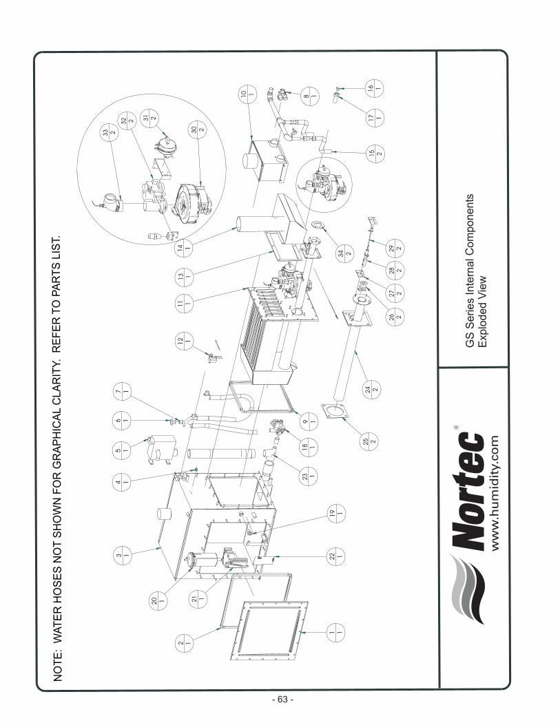
NO
TE
:W
AT
ER
HO
SE
SN
OT
SH
OW
NF
OR
GR
AP
HIC
AL
CLA
RIT
Y.
RE
FE
RT
OP
AR
TS
LIS
T.
GS
Se
rie
sIn
tern
alC
om
po
ne
nts
Exp
lod
ed
Vie
w
30 2
31 2
32 2
33 2
10 1 8 1
12 1
22 1
6 1
14 1
18 1
19 1
5 17 1
9 1
2 1
3 1
1 1
11 1
20 1
4 1
16 1
17 1
13 1
21 1
23 1
15 2
34 2
25 2
26 2
27 2
28 2
29 2
24 2
- 63 -
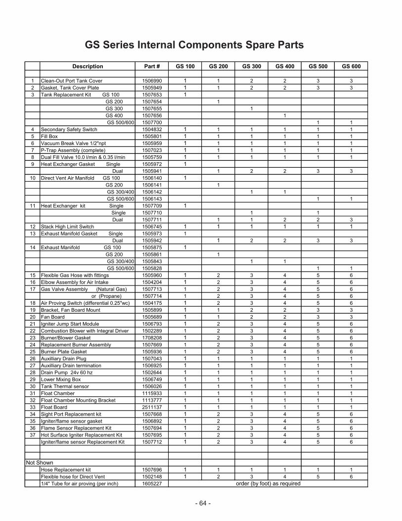
Description Part # GS 100 GS 200 GS 300 GS 400 GS 500 GS 600
1 Clean-Out Port Tank Cover 1506990 1 1 2 2 3 3
2 Gasket, Tank Cover Plate 1505949 1 1 2 2 3 3
3 Tank Replacement Kit GS 100 1507653 1
GS 200 1507654 1
GS 300 1507655 1
GS 400 1507656 1
GS 500/600 1507700 1 1
4 Secondary Safety Switch 1504832 1 1 1 1 1 1
5 Fill Box 1505801 1 1 1 1 1 1
6 Vacuum Break Valve 1/2"npt 1505959 1 1 1 1 1 1
7 P-Trap Assembly (complete) 1507023 1 1 1 1 1 1
8 Dual Fill Valve 10.0 l/min & 0.35 l/min 1505759 1 1 1 1 1 1
9 Heat Exchanger Gasket Single 1505972 1
Dual 1505941 1 2 2 3 3
10 Direct Vent Air Manifold GS 100 1506140 1
GS 200 1506141 1
GS 300/400 1506142 1 1
GS 500/600 1506143 1 1
11 Heat Exchanger kit Single 1507709 1
Single 1507710 1 1
Dual 1507711 1 1 2 2 3
12 Stack High Limit Switch 1506745 1 1 1 1 1 1
13 Exhaust Manifold Gasket Single 1505973 1
Dual 1505942 1 2 2 3 3
14 Exhaust Manifold GS 100 1505875 1
GS 200 1505861 1
GS 300/400 1505843 1 1
GS 500/600 1505828 1 1
15 Flexible Gas Hose with fittings 1505960 1 2 3 4 5 6
16 Elbow Assembly for Air Intake 1504204 1 2 3 4 5 6
17 Gas Valve Assembly (Natural Gas) 1507713 1 2 3 4 5 6
or (Propane) 1507714 1 2 3 4 5 6
18 Air Proving Switch (differential 0.25"wc) 1504175 1 2 3 4 5 6
19 Bracket, Fan Board Mount 1505899 1 1 2 2 3 3
20 Fan Board 1505689 1 1 2 2 3 3
21 Igniter Jump Start Module 1506793 1 2 3 4 5 6
22 Combustion Blower with Integral Driver 1502289 1 2 3 4 5 6
23 Burner/Blower Gasket 1708208 1 2 3 4 5 6
24 Replacement Burner Assembly 1507669 1 2 3 4 5 6
25 Burner Plate Gasket 1505936 1 2 3 4 5 6
26 Auxilliary Drain Plug 1507043 1 1 1 1 1 1
27 Auxilliary Drain termination 1506925 1 1 1 1 1 1
28 Drain Pump 24v 60 hz 1502644 1 1 1 1 1 1
29 Lower Mixing Box 1506749 1 1 1 1 1 1
30 Tank Thermal sensor 1506026 1 1 1 1 1 1
31 Float Chamber 1115933 1 1 1 1 1 1
32 Float Chamber Mounting Bracket 1113777 1 1 1 1 1 1
33 Float Board 2511137 1 1 1 1 1 1
34 Sight Port Replacement kit 1507668 1 2 3 4 5 6
35 Igniter/flame sensor gasket 1506892 1 2 3 4 5 6
36 Flame Sensor Replacement Kit 1507694 1 2 3 4 5 6
37 Hot Surface Igniter Replacement Kit 1507695 1 2 3 4 5 6
Igniter/flame sensor Replacement Kit 1507712 1 2 3 4 5 6
Not Shown
Hose Replacement kit 1507696 1 1 1 1 1 1
Flexible hose for Direct Vent 1502148 1 2 3 4 5 6
1/4" Tube for air proving (per inch) 1605227 order (by foot) as required
GS Series Internal Components Spare Parts
- 64 -
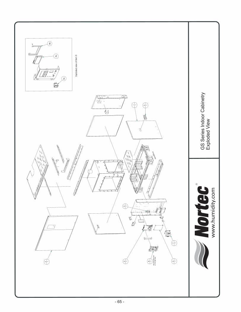
GS
Se
rie
sIn
do
or
Ca
bin
etr
yE
xp
lod
ed
Vie
w
3 1
2 1
7 1
6 15 1 8 1
4 1
See
exp
lod
ed
vie
w
on
the
rightsi
de
1 1
8c
8a
8b
Exp
lod
ed
vie
wo
fite
m8
- 65 -
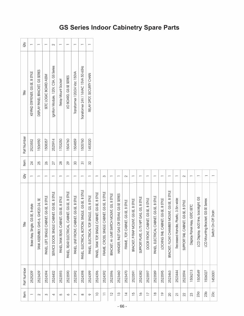
GS Series Indoor Cabinetry Spare PartsIte
mPa
rtN
um
be
rTitle
Qty
12
52
52
09
Base
Ass
y,Si
ng
le,G
S-SE
,B-
styl
e1
22
52
34
39
TAN
KA
SSEM
BLY,
GH
5-6
,G
HE2
0-2
4,SE
1
32
52
43
94
PAN
EL,LE
FT,SI
NG
LEC
ABI
NET
,G
S-SE
,B
STYL
E1
42
52
44
02
SERVIC
ED
OO
R,SI
NG
LEC
ABI
NET
,G
S-SE
,B
STYL
E1
52
52
35
93
PAN
EL,T
AN
KREA
R,C
ABI
NET
,G
S-SE
,B
STYL
E1
62
52
35
90
PAN
EL,REA
REL
ECTR
ICA
L,C
ABI
NET
,G
S-SE
,B
STYL
E1
72
52
35
92
PAN
EL,U
NIT
FRO
NT,
CA
BIN
ET,G
S-SE
,B
STYL
E1
82
52
43
98
PAN
EL,EL
ECTR
ICA
LBO
TTO
M,SI
NG
LE,G
S-SE
,B
STYL
E1
92
52
43
99
PAN
EL,EL
ECTR
ICA
LTO
P,SI
NG
LE,G
S,B
STYL
E1
10
25
24
39
6PA
NEL
,TA
NK
TOP,
SIN
GLE
CA
BIN
ET,G
S-SE
,B
STYL
E1
11
25
24
39
2FR
AM
E,C
RO
SS,SI
NG
LEC
ABI
NET
,G
S-SE
,B
STYL
E3
12
25
23
59
6BR
AC
KET
,H
I-LI
MIT
SWITC
HM
OU
NT,
GS,
BST
YLE
1
13
25
23
46
0H
AN
GER
,IN
LET
GA
SO
RST
EAM
,G
S-SE
SERIE
S1
14
25
23
47
0FR
AM
E,TO
P,C
ABI
NET
,G
S-SE
,B
STYL
E2
15
25
23
59
1BR
AC
KET
,P-
TRA
PM
OU
NT,
GS-
SE,B
STYL
E1
16
25
24
38
2SU
PPO
RT
PLATE
,0
.75
NPT
GA
S,G
S,B
STYL
E1
17
25
23
59
7D
OO
RFR
ON
T,C
ABI
NET
,G
S-SE
,B
STYL
E1
18
25
23
58
9PA
NEL
,EL
ECTR
ICA
LC
ABI
NET
,G
S-SE
,B
STYL
E1
19
25
23
59
5LO
CKIN
GTA
B,C
ABI
NET
,G
S-SE
,B
STYL
E1
20
25
23
46
3BR
AC
KET
,FL
OAT
CH
AM
BER
MO
UN
T,G
S-SE
,B
STYL
E1
21
25
23
44
4Re
ce
sse
dH
and
le,Pl
ast
ic,3
.5in
wid
e1
22
25
23
59
4SU
PPO
RT
TAB,
CA
BIN
ET,G
S-SE
,B
STYL
E2
23
15
06
21
3D
isp
lay
Pane
lAss
y,G
STC
-SET
C1
Item
Part
Num
be
rTitle
Qty
24
25
23
55
2KEY
PAD
STIF
FEN
ER,G
S-SE
,B
STYL
E1
25
15
06
95
0D
ISPL
AY
PAN
ELBR
AC
KET
,G
SSE
RIE
S1
26
15
08
35
7SE
TCLO
GIC
BOA
RD
ASS
M1
27
25
25
91
4Ig
niti
on
Mo
dule
,1
20
V,C
SA,G
SSe
ries
2
28
17
03
25
0Re
lay
Mo
untSo
cke
t1
29
15
04
76
0I/O
BOA
RD
,G
S-SE
SERIE
S1
30
15
04
85
9Tr
ansf
orm
er1
20
/24
Vac
15
0VA
1
31
15
05
76
0Tr
ansf
om
er2
4V
/1
6VA
C1
5VA
50
-60
Hz
1
32
14
53
02
0REL
AY
DPD
T,SE
CU
RIT
YC
HA
IN1
23
a
23
b
23
c
15
04
54
9
15
06
02
7
14
53
00
1
1 1 1
LCD
Dis
pla
y,4
x20
line
,b
ac
klig
ht,
GS
LCD
Mo
untin
gBr
ac
ket,
GS-
SESe
ries
Switc
hO
n-O
ffD
rain
- 66 -

- 67 -
16
19
20
2122
23
24
25
26
27
28
29
30
31
32
34
33
35
36
37
38
39
40
41
43
44
211
7
42
68
9
12
13
14
1
15
31
8
17
41
0
5
GS
Se
rie
sO
utd
oo
rC
ab
ine
try
Exp
lod
ed
Vie
w
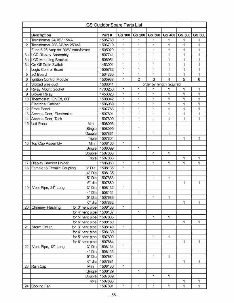
- 68 -
Description Part # GS 100 GS 200 GS 300 GS 400 GS 500 GS 600
1 Transformer 24/16V 15VA 1505760 1 1 1 1 1 1
2 Transformer 208-24Vac 250VA 1506719 1 1 1 1 1 1
Fuse 6.25 Amp for 208V transformer 1505020 1 1 1 1 1 1
3a LCD Display Assembly 1507741 1 1 1 1 1 1
3b LCD Mounting Bracket 1506951 1 1 1 1 1 1
3c On-Off-Drain Switch 1453001 1 1 1 1 1 1
4 Logic Control Board 1505762 1 1 1 1 1 1
5 I/O Board 1504760 1 1 1 1 1 1
6 Ignition Control Module 1505987 1 2 3 4 5 6
7 Slotted wire duct 1506041
8 Relay Mount Socket 1703250 1 1 1 1 1 1
9 Blower Relay 1453020 1 1 1 1 1 1
10 Thermostat, On/Off, 80F 1508042 1 1 1 1 1 1
11 Electrical Cabinet 1506989 1 1 1 1 1 1
12 Front Panel 1507783 1 1 1 1 1 1
13 Access Door, Electronics 1507801 1 1 1 1 1 1
14 Access Door, Tank 1507800 1 1 1 1 1 1
15 Left Panel Mini 1508096 1
Single 1508095 1
Double 1507861 1 1
Triple 1507804 1 1
16 Top Cap Assembly Mini 1508100 1
Single 1508099 1
Double 1507863 1 1
Triple 1507806 1 1
17 Display Bracket Holder 1506950 1 1 1 1 1 1
18 Female to Female Coupling 3" Dia. 1508136 1
4" Dia 1508135 1
5" Dia 1507886 1 1
6" dia 1507880 1 1
19 Vent Pipe, 24" Long 3" Dia 1508132 1
4" Dia 1508131 1
5" Dia 1507888 1 1
6" dia 1507882 1 1
20 Chimney Flashing, for 3" vent pipe 1508138 1
for 4" vent pipe 1508137 1
for 5" vent pipe 1507885 1 1
for 6" vent pipe 1508150 1 1
21 Storm Collar, for 3" vent pipe 1508140 1
for 4" vent pipe 1508139 1
for 5" vent pipe 1507890 1 1
for 6" vent pipe 1507884 1 1
22 Vent Pipe, 12" Long 3" Dia 1508134 1
4" Dia 1508133 1
5" Dia 1507884 1 1
6" dia 1507881 1 1
23 Rain Cap Mini 1508130 1
Single 1508129 1
Double 1507889 1 1
Triple 1507883 1 1
24 Cooling Fan 1507891 1 1 1 1 1 1
order by length required
GS Outdoor Spare Parts List
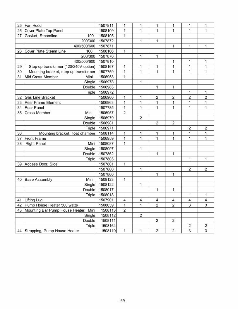
- 69 -
25 Fan Hood 1507811 1 1 1 1 1 1
26 Cover Plate Top Panel 1508109 1 1 1 1 1 1
27 Gasket, Steamline 100 1508105 1
200/300 1507872 1 1
400/500/600 1507871 1 1 1
28 Cover Plate Steam Line 100 1508106 1
200/300 1507870 1 1
400/500/600 1507810 1 1 1
29 Step-up transformer (120/240V option) 1508167 1 1 1 1 1 1
30 Mounting bracket, step-up transformer 1507759 1 1 1 1 1 1
31 Mid Cross Member Mini 1506958 1
Single 1506978 1
Double 1506983 1 1
Triple 1506972 1 1
32 Gas Line Bracket 1506960 1 1 2 2 2 2
33 Rear Frame Element 1506963 1 1 1 1 1 1
34 Rear Panel 1507785 1 1 1 1 1 1
35 Cross Member Mini 1506957 2
Single 1506979 2
Double 1506981 2 2
Triple 1506971 2 2
36 Mounting bracket, float chamber 1508114 1 1 1 1 1 1
37 Front Frame 1506959 1 1 1 1 1 1
38 Right Panel Mini 1508087 1
Single 1508097 1
Double 1507862 1 1
Triple 1507803 1 1
39 Access Door, Side 1507801 1
1507800 1 2 2
1507860 1 1
40 Base Assembly Mini 1508123 1
Single 1508122 1
Double 1508017 1 1
Triple 1508018 1 1
41 Lifting Lug 1507901 4 4 4 4 4 4
42 Pump House Heater 500 watts 1508039 1 1 2 2 3 3
43 Mounting Bar Pump House Heater, Mini 1508113 2
Single 1508112 2
Double 1508111 2 2
Triple 1508164 2 2
44 Strapping, Pump House Heater 1508110 1 1 2 2 3 3
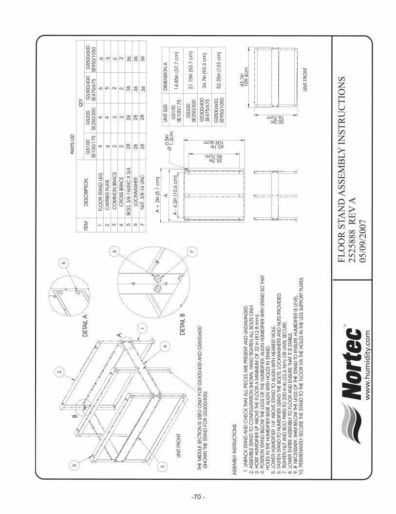
ASS
EM
BLY
INST
RU
CTI
ON
S
1.
UN
PAC
KST
AN
DA
ND
CH
EC
KTH
AT
ALL
PIE
CES
ARE
PRESE
NT
AN
DU
ND
AM
AG
ED
.2
.A
SSEM
BLE
STA
ND
TOC
ON
FIG
URATI
ON
SHO
WN
.H
AN
DTI
GH
TEN
ALL
BO
LTS
ON
LY.
3.
HO
IST
HU
MID
IFIE
RU
PA
BO
VE
THE
FLO
OR
AM
INIM
UM
OF
32
in(8
12
.8m
m).
4.
PO
SITI
ON
STA
ND
BELO
WTH
ELE
GS
OF
THE
HU
MID
IFIE
R.
ALI
GN
HU
MID
IFIE
RW
ITH
STA
ND
SOTH
AT
HO
LES
INTH
EH
UM
IDIF
IER
BA
SEA
LIG
NW
ITH
HO
LES
INST
AN
D.
5.
LOW
ER
HU
MID
IFIE
R1
/4"A
BO
VE
STA
ND
TOA
LIG
NW
ITH
NEA
REST
HO
LE.
6.
FAST
EN
STA
ND
TOH
UM
IDIF
IER
USI
NG
THE
BO
LTS,
LOC
KW
ASH
ERS
AN
DN
UTS
PRO
VID
ED
.7
.TI
GH
TEN
NU
TA
ND
BO
LTPA
IRS
TO2
00
in-lb
(22
.6N
m)O
RU
NTI
LSE
CU
RE.
8.
LOW
ER
EN
TIRE
ASS
EM
BLY
TOFLO
OR
AN
DEN
SURE
THAT
ITIS
STA
BLE
.9
.IF
NEC
ESS
ARY,
SHIM
BELO
WTH
ELE
GS
OF
THE
STA
ND
TOEN
SURE
HU
MID
IFIE
RIS
LEVEL.
10
.PERM
EN
AN
TLY
SEC
URE
THE
STA
ND
TOTH
EFLO
OR
VIA
THE
HO
LES
INTH
ELE
GSU
PPO
RT
PLA
TES.
36
36
36
36
36
28
28
28
28
282
222
22
244
5
28
NU
T,3
/8-1
6U
NC
7
LOC
KW
ASH
ER
6
BO
LT,
3/8
-16
UN
CX
3/4
5
CRO
SSBRA
CE
4
CO
MM
ON
BRA
CE
3
CA
RRIE
RPLA
TE2
FLO
OR
STA
ND
LEG
1
244
56
366
QTY
GS1
00
GS2
00
GS3
00
/40
0G
S50
0/6
00
SE1
00
/17
5SE
25
0/3
00
SE4
75
/67
5SE
95
0/1
05
0
DESC
RIP
TIO
N
PARTS
LIST
ITEM
1
THE
MID
DLE
SEC
TIO
NIS
USE
DO
NLY
FO
RG
S30
0/4
00
AN
DG
S50
0/6
00
(SH
OW
NTH
EST
AN
DFO
RG
S30
0/4
00
)
2
34
UN
ITFRO
NT
5
A
B
DETA
ILA
5
DETA
ILB
6 7
UN
ITFRO
NT
43
.1in
10
9.4
cm
30.2in76.7cm
52
.35
in(1
33
cm
)
36
.7in
(93
.3c
m)
21
.15
in(5
3.7
cm
)
GS5
00
/60
0,
SE9
50
/10
50
GS3
00
/40
0SE
47
5/6
75
GS2
00
SE2
50
/30
0
GS1
00
SE1
00
/17
5
UN
ITSI
ZED
IMEN
SIO
NA
14
.85
in(3
7.7
cm
)
A
A+
2in
(5.1
cm
)
A-
4.2
in(1
0.6
cm
)
43.1in109.4cm
35.7in90.7cm
0.5
in1
.3c
mØ
FL
OO
RS
TA
ND
AS
SE
MB
LY
INS
TR
UC
TIO
NS
25
25
88
8R
EV
A0
5/0
9/2
00
7
-70 -
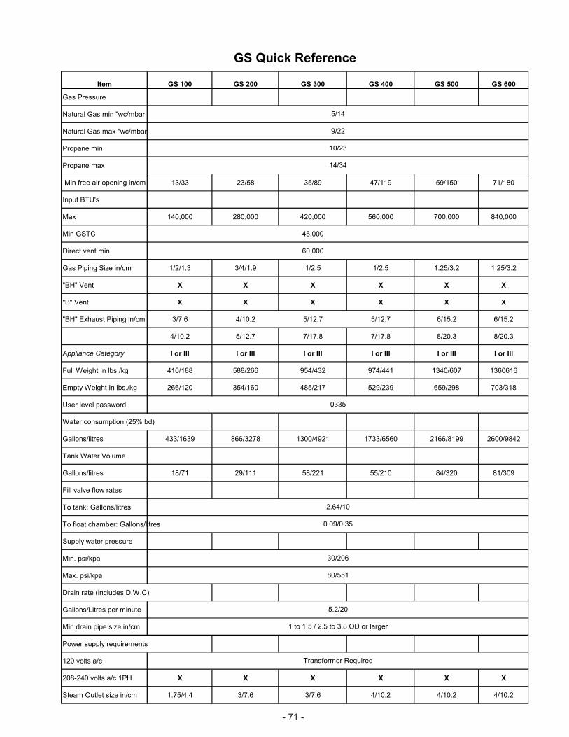
- 71 -
Item GS 100 GS 200 GS 300 GS 400 GS 500 GS 600
Gas Pressure
Natural Gas min "wc/mbar
Natural Gas max "wc/mbar
Propane min
Propane max
Min free air opening in/cm 13/33 23/58 35/89 47/119 59/150 71/180
Input BTU's
Max 140,000 280,000 420,000 560,000 700,000 840,000
Min GSTC 45,000
Direct vent min 60,000
Gas Piping Size in/cm 1/2/1.3 3/4/1.9 1/2.5 1/2.5 1.25/3.2 1.25/3.2
"BH" Vent X X X X X X
"B" Vent X X X X X X
"BH" Exhaust Piping in/cm 3/7.6 4/10.2 5/12.7 5/12.7 6/15.2 6/15.2
4/10.2 5/12.7 7/17.8 7/17.8 8/20.3 8/20.3
Appliance Category I or III I or III I or III I or III I or III I or III
Full Weight In lbs./kg 416/188 588/266 954/432 974/441 1340/607 1360616
Empty Weight In lbs./kg 266/120 354/160 485/217 529/239 659/298 703/318
User level password
Water consumption (25% bd)
Gallons/litres 433/1639 866/3278 1300/4921 1733/6560 2166/8199 2600/9842
Tank Water Volume
Gallons/litres 18/71 29/111 58/221 55/210 84/320 81/309
Fill valve flow rates
To tank: Gallons/litres
To float chamber: Gallons/litres
Supply water pressure
Min. psi/kpa
Max. psi/kpa
Drain rate (includes D.W.C)
Gallons/Litres per minute
Min drain pipe size in/cm
Power supply requirements
120 volts a/c
208-240 volts a/c 1PH X X X X X X
Steam Outlet size in/cm 1.75/4.4 3/7.6 3/7.6 4/10.2 4/10.2 4/10.2
0.09/0.35
5.2/20
1 to 1.5 / 2.5 to 3.8 OD or larger
Transformer Required
30/206
80/551
0335
2.64/10
14/34
9/22
10/23
GS Quick Reference
5/14

LIMITED WARRANTY
AXAIR NORTEC INCORPORATED and/or AXAIR NORTEC LIMITED (hereinafter collectivelyreferred to as THE COMPANY), warrant for a period of two years from date of shipment, that THECOMPANY's manufactured and assembled products, not otherwise expressly warranted, are free fromdefects in material and workmanship. No warranty is made against corrosion, deterioration, or suitabilityof substituted materials used as a result of compliance with government regulations.
THE COMPANY's obligations and liabilities under this warranty are limited to furnishing replacementparts to the customer, F.O.B. THE COMPANY's factory, providing the defective part(s) is returned freightprepaid by the customer. Parts used for repairs are warranted for the balance of the term of the warrantyon the original humidifier or 90 days, whichever is longer.
The warranties set forth herein are in lieu of all other warranties expressed or implied by law. Noliability whatsoever shall be attached to THE COMPANY until said products have been paid for in full andthen said liability shall be limited to the original purchase price for the product. Any further warranty mustbe in writing, signed by an officer of THE COMPANY.
THE COMPANY's limited warranty on accessories, not of NORTEC's manufacture, such as controls,humidistats, pumps, etc. is limited to the warranty of the original equipment manufacturer from date oforiginal shipment of humidifier.
THE COMPANY makes no warranty and assumes no liability unless the equipment is installed instrict accordance with a copy of the catalog and installation manual in effect at the date of purchase andby a contractor approved by THE COMPANY to install such equipment.
THE COMPANY makes no warranty and assumes no liability whatsoever for consequential damageor damage resulting directly from misapplication, incorrect sizing or lack of proper MAINTENANCE of theequipment.
THE COMPANY retains the right to change the design, specification and performance criteria of itsproducts without notice or obligation.
PR
INT
ED
INC
AN
AD
A
A WMH COMPANY
- www.humidity.com -U.S.A. - AxAir NORTEC Inc. 826 Proctor Avenue, Ogdensburg, New York, 13669
CANADA - AxAir NORTEC Ltd. 2740 Fenton Road, Ottawa, ON, K1T 3T71-(866) NORTEC-1 Fax - (613) 822-7964