Embed Size (px)
Citation preview
Manufacturer reserves the right to discontinue, or change at any time, specifications or designs without notice and without incurring obligations.Catalog No. 04-53500103-01 Printed in U.S.A. Form 50PSW-3SI Pg 1 8-14 Replaces: NEW
Installation, Start-Up, andService Instructions
CONTENTSPage
SAFETY CONSIDERATIONS . . . . . . . . . . . . . . . . . . .1,2GENERAL . . . . . . . . . . . . . . . . . . . . . . . . . . . . . . . . . . . . . . . . 2INSTALLATION . . . . . . . . . . . . . . . . . . . . . . . . . . . . . 2-16Step 1 — Check Jobsite . . . . . . . . . . . . . . . . . . . . . . . . 2Step 2 — Check Unit . . . . . . . . . . . . . . . . . . . . . . . . . . . 2• STORAGE• PROTECTION• INSPECT UNITStep 3 — Locate Unit . . . . . . . . . . . . . . . . . . . . . . . . . . . . . 6Step 4 — Mount Unit . . . . . . . . . . . . . . . . . . . . . . . . . . . . . 6Step 5 — Connect Piping. . . . . . . . . . . . . . . . . . . . . . . . . 6• WATER SUPPLY AND QUALITY• COOLING TOWER/BOILER APPLICATION• WELL WATER SYSTEMS• EARTH COUPLED GEOTHERMAL SYSTEMSStep 6 — Wire Electrical Connections . . . . . . . . . . . 11PRE-START-UP . . . . . . . . . . . . . . . . . . . . . . . . . . . . . . . . . . 16System Checkout . . . . . . . . . . . . . . . . . . . . . . . . . . . . . 16FIELD SELECTABLE INPUTS . . . . . . . . . . . . . . . 16-18Safety Devices and the Complete C Controller . . 16START-UP . . . . . . . . . . . . . . . . . . . . . . . . . . . . . . . . . . . . .19,20Operating Limits . . . . . . . . . . . . . . . . . . . . . . . . . . . . . . . . 19Unit Start-Up . . . . . . . . . . . . . . . . . . . . . . . . . . . . . . . . . . . . 19Scroll Compressor Rotation. . . . . . . . . . . . . . . . . . . . . 19Cleaning and Flushing . . . . . . . . . . . . . . . . . . . . . . . . . . 19Antifreeze . . . . . . . . . . . . . . . . . . . . . . . . . . . . . . . . . . . . . . . 20Cooling Tower/Boiler Systems . . . . . . . . . . . . . . . . . . 20Ground Coupled, Closed Loop and Plateframe
Heat Exchanger Well Systems . . . . . . . . . . . . . . . . 20OPERATION . . . . . . . . . . . . . . . . . . . . . . . . . . . . . . . . . . .20,21Power Up Mode . . . . . . . . . . . . . . . . . . . . . . . . . . . . . . . . . 20Units with Aquazone Complete C Control . . . . . . . 20Off Mode . . . . . . . . . . . . . . . . . . . . . . . . . . . . . . . . . . . . . . . . 20Heating Mode . . . . . . . . . . . . . . . . . . . . . . . . . . . . . . . . . . . 21Cooling Mode . . . . . . . . . . . . . . . . . . . . . . . . . . . . . . . . . . . 21Retry Mode. . . . . . . . . . . . . . . . . . . . . . . . . . . . . . . . . . . . . . 21SERVICE . . . . . . . . . . . . . . . . . . . . . . . . . . . . . . . . . . . . . .21,22Water Coil . . . . . . . . . . . . . . . . . . . . . . . . . . . . . . . . . . . . . . . 21Refrigerant System. . . . . . . . . . . . . . . . . . . . . . . . . . . . . . 21Condenser Cleaning . . . . . . . . . . . . . . . . . . . . . . . . . . . . 22Checking System Charge . . . . . . . . . . . . . . . . . . . . . . . 22Refrigerant Charging . . . . . . . . . . . . . . . . . . . . . . . . . . . . 22TROUBLESHOOTING. . . . . . . . . . . . . . . . . . . . . . . . . .22,2350PSW START-UP CHECKLIST . . . . . . . . . . . CL-1,CL-2
SAFETY CONSIDERATIONSInstallation and servicing of air-conditioning equipment can
be hazardous due to system pressure and electrical compo-nents. Only trained and qualified service personnel shouldinstall, repair, or service air-conditioning equipment.
Untrained personnel can perform basic maintenance func-tion of cleaning coils. All other operations should be performedby trained service personnel. When working on air-condition-ing equipment, observe precautions in the literature, tags andlabels attached to the unit, and other safety precautions thatmay apply.
Improper installation, adjustment, alteration, service, main-tenance, or use can cause explosion, fire, electrical shock orother conditions which may cause personal injury or propertydamage. Consult a qualified installer, service agency, or yourdistributor or branch for information or assistance. Thequalified installer or agency must use factory-authorized kits oraccessories when modifying this product. Refer to the individ-ual instructions packaged with the kits or accessories wheninstalling.
Follow all safety codes. Wear safety glasses and workgloves. Use quenching cloth for brazing operations. Have fireextinguisher available. Read these instructions thoroughly andfollow all warnings or cautions attached to the unit. Consultlocal building codes and the National Electrical Code (NEC)for special installation requirements.
Understand the signal words — DANGER, WARNING,and CAUTION. DANGER identifies the most serious hazardswhich will result in severe personal injury or death. WARN-ING signifies hazards that could result in personal injury ordeath. CAUTION is used to identify unsafe practices, whichwould result in minor personal injury or product and propertydamage.
Recognize safety information. This is the safety alertsymbol ( ). When you see this symbol on the unit and ininstructions or manuals, be alert to the potential for personalinjury.
IMPORTANT: Read the entire instruction manual beforestarting installation.
WARNING
Electrical shock can cause personal injury or death. Beforeinstalling or servicing system, always turn off main powerto system. There may be more than one disconnect switch.Turn off accessory heater power if applicable. Install lock-out tag.
Aquazone™50PSW025-420
Water-to-Water Source Heat Pumpwith Puron® Refrigerant (R-410A)

2
GENERALThe Aquazone™ 50PSW water source heat pump (WSHP)
is a single-package vertically mounted unit with electronic con-trols designed for year-round cooling and heating.
INSTALLATION
Step 1 — Check Jobsite — Installation, operation andmaintenance instructions are provided with each unit. Beforeunit start-up, read all manuals and become familiar with theunit and its operation. Thoroughly check out the system beforeoperation. Complete the inspections and instructions listed
below to prepare a unit for installation. See Tables 1 and 2 forunit physical data.
Units are designed for indoor installation only. Be sure to al-low adequate space around the unit for servicing. See Fig. 1-3for overall unit dimensions.
These units are not approved for outdoor installation andmust be installed indoors in the structure being conditioned. Donot locate in areas where ambient conditions are not main-tained within 40 to 100 F.
Step 2 — Check Unit — Upon receipt of shipment atthe jobsite, carefully check the shipment against the bill oflading. Make sure all units have been received. Inspect the car-ton or crating of each unit, and inspect each unit for damage.Ensure the shipping company makes proper notation of anyshortages or damage on all copies of the freight bill. Concealeddamage not discovered during unloading must be reported tothe shipping company within 15 days of receipt of shipment.NOTE: It is the responsibility of the purchaser to file allnecessary claims with the shipping company.
1. Verify unit is correct model for entering water tempera-ture of job.
2. Be sure the location chosen for unit installation providesambient temperatures maintained above freezing. Wellwater applications are especially susceptible to freezing.
3. Be sure the installation location is isolated from sleepingareas, private offices and other acoustically sensitivespaces.NOTE: A sound control accessory package may be usedto help eliminate sound in sensitive spaces.
4. Provide sufficient access to allow maintenance andservicing of the compressor and coils.
5. Provide an unobstructed path to the unit within the closetor mechanical room. Space should be sufficient to allowremoval of unit if necessary.
6. Provide ready access to water valves and fittings, andscrewdriver access to unit side panels.
7. Where access to side panels is limited, pre-removal of thecontrol box side mounting screws may be necessary forfuture servicing.
STORAGE — If the equipment is not needed for immediateinstallation upon its arrival at the jobsite, it should be left in itsshipping carton and stored in a clean, dry area of the buildingor in a warehouse. Units must be stored in an upright positionat all times. If carton stacking is necessary, stack units a maxi-mum of 3 cartons high. Do not remove any equipment from itsshipping package until it is needed for installation.
Table 1 — 50PSW 025-071 Unit Physical Data
WARNING
DO NOT USE TORCH to remove any component. Systemcontains oil and refrigerant under pressure.To remove a component, wear protective gloves and gog-gles and proceed as follows:a. Shut off electrical power to unit.b. Recover refrigerant to relieve all pressure from sys-
tem using both high-pressure and low pressure ports.c. Traces of vapor should be displaced with nitrogen
and the work area should be well ventilated. Refrig-erant in contact with an open flame produces toxicgases.
d. Cut component connection tubing with tubing cutterand remove component from unit. Use a pan to catchany oil that may come out of the lines and as a gagefor how much oil to add to the system.
e. Carefully unsweat remaining tubing stubs when nec-essary. Oil can ignite when exposed to torch flame.
Failure to follow these procedures may result in personalinjury or death.
CAUTION
DO NOT re-use compressor oil or any oil that has beenexposed to the atmosphere. Dispose of oil per local codesand regulations. DO NOT leave refrigerant system open toair any longer than the actual time required to service theequipment. Seal circuits being serviced and charge withdry nitrogen to prevent oil contamination when timelyrepairs cannot be completed. Failure to follow these proce-dures may result in damage to equipment.
IMPORTANT: The installation of water source heat pumpunits and all associated components, parts, and accessorieswhich make up the installation shall be in accordance withthe regulations of ALL authorities having jurisdiction andMUST conform to all applicable codes. It is the responsi-bility of the installing contractor to determine and complywith ALL applicable codes and regulations.
CAUTION
To avoid equipment damage, do not use these units as asource of heating or cooling during the construction pro-cess. The mechanical components used in these units canquickly become clogged with construction dirt and debriswhich may cause system damage.
50PSW UNIT SIZE 025 035 049 061 071Compressor Type Scroll Scroll Scroll Scroll ScrollQuantity 1 1 1 1 1Maximum Water Working Pressure (psig/kPa)
400/3100 400/3100 400/3100 400/3100 400/3100
Water Connection Size (in.) FPT 3/4 3/4 1 1 1Refrigeration Charge (oz/ckt) 48 59 62 72 90Operating Weight (lb) 240 250 280 310 430Shipping Weight (lb) 260 270 300 330 450

3
Table 2 — 50PSW 122-420 Unit Physical Data
50PSW UNIT SIZE 122 180 210 240 360 420Compressor Type Scroll Scroll Scroll Scroll Scroll ScrollQuantity 2 1 1 2 2 2Maximum Water Working Pressure (psig/kPa) 400/3100 400/3100 400/3100 400/3100 400/3100 400/3100
Water Connection Size (in.) FPT 11/4 11/2 11/2 2 2 2Refrigeration Charge (oz/ckt) 85 210 220 140 210 220Operating Weight (lb) 720 850 890 1230 1550 1700Shipping Weight (lb) 740 870 910 1260 1580 1730
Fig. 1 — 50PSW025-071 Unit
T
Q R S
24.0
LEFT SIDEUNIT FRONT
L
K
H
J32.5
E
D
F
24.0
G
P
MN
LEGEND
*Refers to both load and source fluid connections. NOTES:All dimensions are within ± 0.125 in. Specifications subject to change without notice.
UNIT SIZE
DIMENSIONS (INCHES) FIELD CONN.*
HRP CONN.D E F G H J K L M N P Q R S T
025 2.70 2.50 13.70 2.50 3.25 1.95 14.25 1.95 7.15 11.00 4.25 6.55 8.05 9.55 1.25 3/4 1/2035 2.30 2.30 14.30 2.50 3.70 2.55 15.70 2.55 7.15 11.00 4.25 6.55 8.05 9.55 1.25 3/4 1/2049 2.30 2.60 14.30 2.65 3.70 2.65 15.70 2.65 7.15 11.00 4.25 6.55 8.05 9.55 1.25 1 1/2061 2.30 2.60 14.30 2.65 3.20 2.65 15.20 2.65 7.15 11.00 4.25 6.55 8.05 9.55 1.25 1 1/2071 2.50 2.60 21.75 4.45 2.50 2.45 21.75 2.65 7.15 11.00 4.25 6.55 8.05 9.55 1.25 1 1/2
HRP — Heat Recovery Package
4
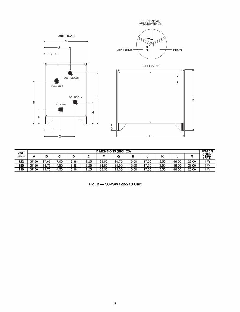
Fig. 2 — 50PSW122-210 Unit
K
L
A
LEFT SIDE
C
B
DH
F
E
G
M
J
SOURCE OUT
SOURCE IN
LOAD OUT
LOAD IN
UNIT REAR
ELECTRICALCONNECTIONS
FRONTLEFT SIDE
UNIT SIZE
DIMENSIONS (INCHES) WATER CONN.(FPT)A B C D E F G H J K L M
122 37.50 27.62 7.00 8.38 9.25 33.50 20.75 13.50 17.50 3.50 46.00 28.00 11/4180 37.50 19.75 4.50 8.38 9.25 33.50 24.00 13.50 17.50 3.50 46.00 28.00 11/2210 37.50 19.75 4.50 8.38 9.25 33.50 23.50 13.50 17.50 3.50 46.00 28.00 11/2

5
PROTECTION — Once the units are properly positioned onthe jobsite, they must be covered with either a shipping carton,vinyl film, or an equivalent protective covering. Open ends ofpipes stored on the jobsite must be capped. This precaution isespecially important in areas where painting, plastering, orspraying of fireproof material, etc., is not yet complete. Foreignmaterial that is allowed to accumulate within the units can pre-vent proper start-up and necessitate costly clean-up operations.
Before installing any of the system components, be sure toexamine each pipe, fitting, and valve, and remove any dirt orforeign material found in or on these components.
Fig. 3 — 50PSW240-420 Unit
UNIT SIZE
DIMENSIONS (INCHES) WATER CONN.(FPT)A B C D E F G H J K L M
240 70.00 44.00 8.50 24.50 10.50 49.00 17.50 30.00 20.50 3.50 46.00 28.00 2360 70.00 44.00 4.50 24.50 10.50 49.00 17.50 30.00 23.50 3.50 46.00 28.00 2420 70.00 44.00 4.50 24.50 10.50 49.00 17.50 30.00 23.50 3.50 46.00 28.00 2
K
L
LOAD OUT
SOURCE OUT
SOURCE IN
LOAD IN
C
B
DH
F
EJ
MG
UNIT REAR
A
LEFT SIDE
ELECTRICALCONNECTIONS
FRONTLEFT SIDE
CAUTION
DO NOT store or install units in corrosive environments orin locations subject to temperature or humidity extremes(e.g., attics, garages, rooftops, etc.). Corrosive conditionsand high temperature or humidity can significantly reduceperformance, reliability, and service life. Always moveunits in an upright position. Tilting units on their sides maycause equipment damage.
6
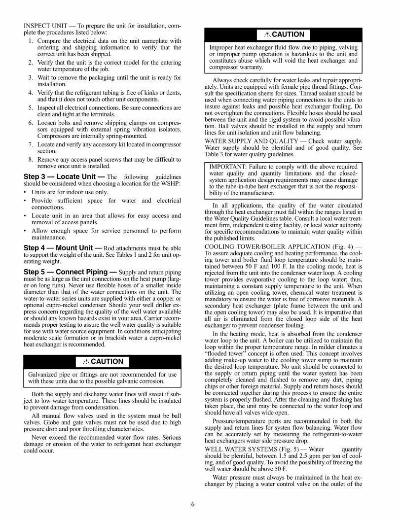
INSPECT UNIT — To prepare the unit for installation, com-plete the procedures listed below:
1. Compare the electrical data on the unit nameplate withordering and shipping information to verify that thecorrect unit has been shipped.
2. Verify that the unit is the correct model for the enteringwater temperature of the job.
3. Wait to remove the packaging until the unit is ready forinstallation.
4. Verify that the refrigerant tubing is free of kinks or dents,and that it does not touch other unit components.
5. Inspect all electrical connections. Be sure connections areclean and tight at the terminals.
6. Loosen bolts and remove shipping clamps on compres-sors equipped with external spring vibration isolators.Compressors are internally spring-mounted.
7. Locate and verify any accessory kit located in compressorsection.
8. Remove any access panel screws that may be difficult toremove once unit is installed.
Step 3 — Locate Unit — The following guidelinesshould be considered when choosing a location for the WSHP:• Units are for indoor use only.• Provide sufficient space for water and electrical
connections.• Locate unit in an area that allows for easy access and
removal of access panels.• Allow enough space for service personnel to perform
maintenance.
Step 4 — Mount Unit — Rod attachments must be ableto support the weight of the unit. See Tables 1 and 2 for unit op-erating weight.
Step 5 — Connect Piping — Supply and return pipingmust be as large as the unit connections on the heat pump (larg-er on long runs). Never use flexible hoses of a smaller insidediameter than that of the water connections on the unit. Thewater-to-water series units are supplied with either a copper oroptional cupro-nickel condenser. Should your well driller ex-press concern regarding the quality of the well water availableor should any known hazards exist in your area, Carrier recom-mends proper testing to assure the well water quality is suitablefor use with water source equipment. In conditions anticipatingmoderate scale formation or in brackish water a cupro-nickelheat exchanger is recommended.
Both the supply and discharge water lines will sweat if sub-ject to low water temperature. These lines should be insulatedto prevent damage from condensation.
All manual flow valves used in the system must be ballvalves. Globe and gate valves must not be used due to highpressure drop and poor throttling characteristics.
Never exceed the recommended water flow rates. Seriousdamage or erosion of the water to refrigerant heat exchangercould occur.
Always check carefully for water leaks and repair appropri-ately. Units are equipped with female pipe thread fittings. Con-sult the specification sheets for sizes. Thread sealant should beused when connecting water piping connections to the units toinsure against leaks and possible heat exchanger fouling. Donot overtighten the connections. Flexible hoses should be usedbetween the unit and the rigid system to avoid possible vibra-tion. Ball valves should be installed in the supply and returnlines for unit isolation and unit flow balancing.WATER SUPPLY AND QUALITY — Check water supply.Water supply should be plentiful and of good quality. SeeTable 3 for water quality guidelines.
In all applications, the quality of the water circulatedthrough the heat exchanger must fall within the ranges listed inthe Water Quality Guidelines table. Consult a local water treat-ment firm, independent testing facility, or local water authorityfor specific recommendations to maintain water quality withinthe published limits.COOLING TOWER/BOILER APPLICATION (Fig. 4) —To assure adequate cooling and heating performance, the cool-ing tower and boiler fluid loop temperature should be main-tained between 50 F and 100 F. In the cooling mode, heat isrejected from the unit into the condenser water loop. A coolingtower provides evaporative cooling to the loop water; thus,maintaining a constant supply temperature to the unit. Whenutilizing an open cooling tower, chemical water treatment ismandatory to ensure the water is free of corrosive materials. Asecondary heat exchanger (plate frame between the unit andthe open cooling tower) may also be used. It is imperative thatall air is eliminated from the closed loop side of the heatexchanger to prevent condenser fouling.
In the heating mode, heat is absorbed from the condenserwater loop to the unit. A boiler can be utilized to maintain theloop within the proper temperature range. In milder climates a“flooded tower” concept is often used. This concept involvesadding make-up water to the cooling tower sump to maintainthe desired loop temperature. No unit should be connected tothe supply or return piping until the water system has beencompletely cleaned and flushed to remove any dirt, pipingchips or other foreign material. Supply and return hoses shouldbe connected together during this process to ensure the entiresystem is properly flushed. After the cleaning and flushing hastaken place, the unit may be connected to the water loop andshould have all valves wide open.
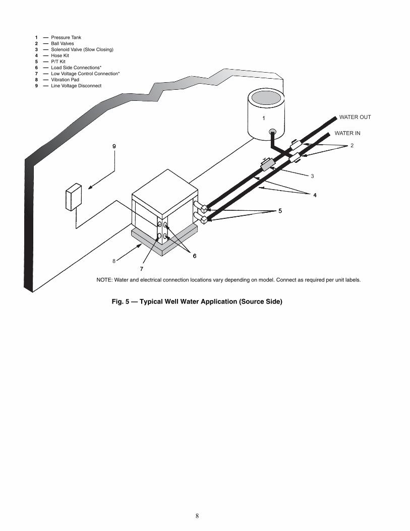
Pressure/temperature ports are recommended in both thesupply and return lines for systen flow balancing. Water flowcan be accurately set by measuring the refrigerant-to-waterheat exchangers water side pressure drop.WELL WATER SYSTEMS (Fig. 5) — Water quantityshould be plentiful, between 1.5 and 2.5 gpm per ton of cool-ing, and of good quality. To avoid the possibility of freezing thewell water should be above 50 F.
Water pressure must always be maintained in the heat ex-changer by placing a water control valve on the outlet of the
CAUTION
Galvanized pipe or fittings are not recommended for usewith these units due to the possible galvanic corrosion.
CAUTION
Improper heat exchanger fluid flow due to piping, valvingor improper pump operation is hazardous to the unit andconstitutes abuse which will void the heat exchanger andcompressor warranty.
IMPORTANT: Failure to comply with the above requiredwater quality and quantity limitations and the closed-system application design requirements may cause damageto the tube-in-tube heat exchanger that is not the responsi-bility of the manufacturer.

7
water-to-water unit. A bladder type expansion tank may beused to maintain pressure on the system.
Avoid using low voltage (24 volt) solenoids, using themmay overload the unit transformer or interfere with the lock-outcircuit. Line voltage solenoids connected across the load side(T1, T2) of the compressor contactor are preferred.
Pilot operated or slow closing valves are recommended toreduce water hammer.
The discharge water from the water-to-water unit is not con-taminated in any manner and can be disposed of in variousways depending on the local codes (i.e. discharge well, drywell, storm sewer, drain field, stream, pond, etc.)
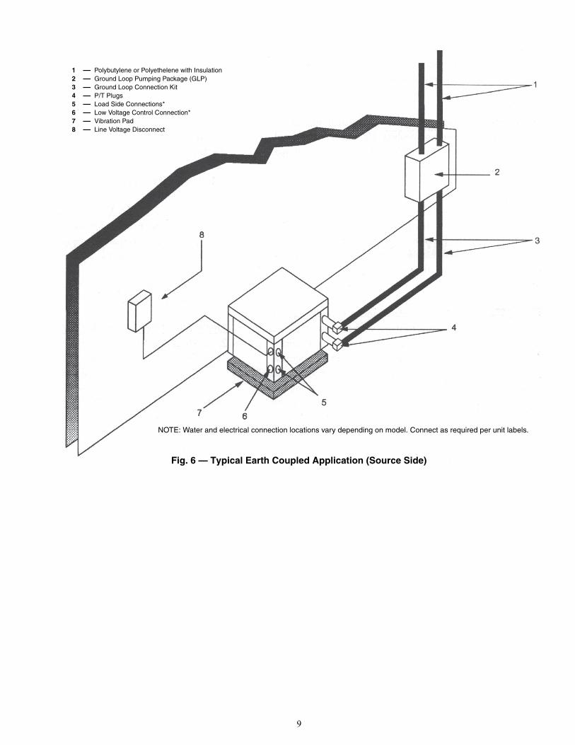
EARTH COUPLED GEOTHERMAL SYSTEMS(Fig. 6) — Closed loop and pond applications require special-ized design knowledge. No attempt at these installationsshould be made unless the dealer has received specializedtraining.
Utilizing the Ground Loop Pumping Package (GLP), makesthe installation easy. Anti-freeze solutions are utilized when en-tering loop temperatures drop below 40 F or where piping willbe routed through areas subject to freezing. A flow rate be-tween 2.5 to 3.0 gpm per nominal ton of cooling is recom-mended for this application.
Fig. 4 — Typical Tower/Boiler Application (Source Side)
NOTE: Water and electrical connection locations vary depending on model. Connect as required per unit labels.
1 — Ball Valves2 — Hose Kits3 — P/T Plugs4 — Load Side Connections*5 — Low Voltage Control Connection*6 — Vibration Pad7 — Line Voltage Disconnect8 — Supply and Return Lines of Central System
8
WATER OUT
WATER IN
2
3
8
Fig. 5 — Typical Well Water Application (Source Side)
NOTE: Water and electrical connection locations vary depending on model. Connect as required per unit labels.
1 — Pressure Tank2 — Ball Valves3 — Solenoid Valve (Slow Closing)4 — Hose Kit5 — P/T Kit6 — Load Side Connections*7 — Low Voltage Control Connection*8 — Vibration Pad9 — Line Voltage Disconnect
9
Fig. 6 — Typical Earth Coupled Application (Source Side)
NOTE: Water and electrical connection locations vary depending on model. Connect as required per unit labels.
1 — Polybutylene or Polyethelene with Insulation2 — Ground Loop Pumping Package (GLP)3 — Ground Loop Connection Kit4 — P/T Plugs5 — Load Side Connections*6 — Low Voltage Control Connection*7 — Vibration Pad8 — Line Voltage Disconnect

10
Table 3 — Water Quality Guidelines
LEGEND
*Heat exchanger materials considered are copper, cupronickel,304 SS (stainless steel), 316 SS, titanium.
†Closed recirculating system is identified by a closed pressurizedpiping system.
**Recirculating open wells should observe the open recirculatingdesign considerations.
††If the concentration of these corrosives exceeds the maximumallowable level, then the potential for serious corrosion problemsexists.Sulfides in the water quickly oxidize when exposed to air, requir-ing that no agitation occur as the sample is taken. Unless testedimmediately at the site, the sample will require stabilization with afew drops of one Molar zinc acetate solution, allowing accuratesulfide determination up to 24 hours after sampling. A low pH andhigh alkalinity cause system problems, even when both values arewithin ranges shown. The term pH refers to the acidity, basicity, orneutrality of the water supply. Below 7.0, the water is consideredto be acidic. Above 7.0, water is considered to be basic. Neutralwater contains a pH of 7.0.To convert ppm to grains per gallon, divide by 17. Hardness inmg/l is equivalent to ppm.
CONDITION HXMATERIAL*
CLOSED RECIRCULATING† OPEN LOOP AND RECIRCULATING WELL**
Scaling Potential — Primary MeasurementAbove the given limits, scaling is likely to occur. Scaling indexes should be calculated using the limits below.
pH/CalciumHardness Method All N/A pH < 7.5 and Ca Hardness, <100 ppm
Index Limits for Probable Scaling Situations (Operation outside these limits is not recommended.)Scaling indexes should be calculated at 150 F for direct use and HWG applications, and at 90 F for indirect HX use. A monitoring plan should be implemented.
Ryznar Stability Index All N/A 6.0 - 7.5If >7.5 minimize steel pipe use.
Langelier Saturation IndexAll N/A
–0.5 to +0.5If <–0.5 minimize steel pipe use.
Based upon 150 F HWG and direct well, 85 F indirect well HX.Iron Fouling
Iron Fe2+ (Ferrous)(Bacterial Iron Potential) All N/A
<0.2 ppm (Ferrous)If Fe2+ (ferrous) >0.2 ppm with pH 6 - 8, O2<5 ppm check for
iron bacteria.Iron Fouling All N/A <0.5 ppm of Oxygen
Above this level deposition will occur.Corrosion Prevention††
pH All 6 - 8.5Monitor/treat as needed.
6 - 8.5Minimize steel pipe below 7 and no open tanks with pH <8.
Hydrogen Sulfide (H2S)
All N/A
<0.5 ppmAt H2S>0.2 ppm, avoid use of copper and cupronickel piping of HXs.
Rotten egg smell appears at 0.5 ppm level.Copper alloy (bronze or brass) cast components are okay to <0.5 ppm.
Ammonia Ion as Hydrox-ide, Chloride, Nitrate and Sulfate Compounds
All N/A<0.5 ppm
Maximum Chloride Levels Maximum allowable at maximum water temperature.50 F (10 C) 75 F (24 C) 100 F (38 C)
Copper N/A <20 ppm NR NRCupronickel N/A <150 ppm NR NR
304 SS N/A <400 ppm <250 ppm <150 ppm316 SS N/A <1000 ppm <550 ppm <375 ppm
Titanium N/A >1000 ppm >550 ppm >375 ppmErosion and Clogging
Particulate Size andErosion
All
<10 ppm of particles and a maximum velocity of
6 fps.Filtered for maximum
800 micron size.
<10 ppm (<1 ppm “sandfree” for reinjection) of particles and a maxi-mum velocity of 6 fps. Filtered for maximum 800 micron size. Any par-ticulate that is not removed can potentially clog components.
HWG— Hot Water GeneratorHX — Heat Exchanger
N/A —Design Limits Not Applicable Consid-ering Recirculating Potable Water
NR — Application Not RecommendedSS — Stainless Steel

11
Step 6 — Wire Electrical Connections All field wiring must comply with local and national fire,safety and electrical codes. Power to the unit must be within theoperating voltage range indicated on the unit’s nameplate. Onthree phase units, phases must be balanced within 2%.
Properly sized fuse or HACR (heating, air-conditioning,and refrigeration) circuit breakers must be installed for branchcircuit protection. See equipment rating plate for maximumsize.
The unit is supplied with an opening for attaching conduit.Be certain to connect the ground lead to the ground lug in thecontrol box. Connect the power leads as indicated on the unitwiring diagram. See Table 4 and Fig. 7-10.
Table 4 — 50PSW Electrical Data
LEGEND
WARNING
To avoid possible injury or death due to electrical shock,open the power supply disconnect switch and secure it inan open position during installation. Install lockout tag.
CAUTION
Use only copper conductors for field-installed electricalwiring. Unit terminals are not designed to accept othertypes of conductors. Failure to heed this warning couldresult in equipment damage.
50PSW UNITSIZE
VOLTAGE(V-Ph-Hz)
COMPRESSORMCA MAX FUSE
QTY RLA LRA
025208/230-1-60 1 11.7 58.3 14.6 25
265-1-60 1 9.1 54.0 11.4 20208/230-3-60 1 6.5 55.4 8.1 15
035
208/230-1-60 1 15.3 83.0 19.1 30265-1-60 1 13.0 72.0 16.3 25
208/230-3-60 1 11.6 73.0 11.6 25460-3-60 1 5.7 38.0 7.1 15
049208/230-1-60 1 21.2 104.0 26.5 45208/230-3-60 1 14.0 83.1 17.5 30
460-3-60 1 6.4 41.0 8.0 15
061208/230-1-60 1 27.1 152.9 33.9 60208/230-3-60 1 16.5 110.0 20.6 35
460-3-60 1 7.2 52.0 9.0 15
071208/230-1-60 1 29.7 179.2 37.1 60208/230-3-60 1 17.6 136.0 22.0 35
460-3-60 1 8.5 66.1 10.6 15
122208/230-1-60 2 28.3 178.0 63.7 90208/230-3-60 2 19.2 136.0 43.2 60
460-3-60 2 8.7 66.1 19.6 25
180208/230-3-60 1 48.1 245.0 60.1 100
460-3-60 1 18.6 125.0 23.3 40575-3-60 1 14.7 100.0 18.4 30
210208/230-3-60 1 55.8 340.0 69.8 125
460-3-60 1 26.9 173.0 33.6 60575-3-60 1 23.7 132.0 29.6 50
240208/230-3-60 2 33.3 239.0 74.9 100
460-3-60 2 17.9 125.0 40.3 50575-3-60 2 12.8 80.0 28.8 40
360208/230-3-60 2 48.1 245.0 108.2 150
460-3-60 2 18.6 125.0 41.9 60575-3-60 2 14.7 100.0 33.1 45
420208/230-3-60 2 55.8 340.0 125.6 175
460-3-60 2 26.9 173.0 60.5 80575-3-60 2 23.7 132.0 53.3 70
LRA — Locked Rotor AmpsMCA — Minimum Circuit AmpsRLA — Rated Load Amps

12
CO
MP
LETE
C IN
CLU
DE
S B
UIL
T IN
: 270
-300
SE
CO
ND
RA
ND
OM
STA
RT
300
SE
CO
ND
DE
LAY
ON
BR
EA
K
12
0 S
EC
ON
D L
OW
PR
ES
SU
RE
BY
PAS
S
DE
FAU
LT S
ETT
ING
S F
OR
CO
MP
LETE
C B
OA
RD
FR
OM
FA
CTO
RY
SH
OW
N
Fig
. 7 —
Un
it S
izes
025
-071
, Sin
gle
-Ph
ase
Co
mp
lete
C C
on
tro
l Bo
ard

13
CO
MP
LETE
C IN
CLU
DE
S B
UIL
T IN
: 270
-300
SE
CO
ND
RA
ND
OM
STA
RT
300
SE
CO
ND
DE
LAY
ON
BR
EA
K
12
0 S
EC
ON
D L
OW
PR
ES
SU
RE
BY
PAS
S
DE
FAU
LT S
ETT
ING
S F
OR
CO
MP
LETE
C B
OA
RD
FR
OM
FA
CTO
RY
SH
OW
N
Fig
. 8 —
Un
it S
ize
122,
Sin
gle
-Ph
ase
Co
mp
lete
C C
on
tro
l Bo
ard

14
CO
MP
LETE
C IN
CLU
DE
S B
UIL
T IN
: 270
-300
SE
CO
ND
RA
ND
OM
STA
RT
300
SE
CO
ND
DE
LAY
ON
BR
EA
K
12
0 S
EC
ON
D L
OW
PR
ES
SU
RE
BY
PAS
S
DE
FAU
LT S
ETT
ING
S F
OR
CO
MP
LETE
C B
OA
RD
FR
OM
FA
CTO
RY
SH
OW
N
Fig
. 9 —
Un
it S
izes
025
-071
, 180
, an
d 2
10, 3
-Ph
ase
Co
mp
lete
C C
on
tro
l Bo
ard

15
CO
MP
LETE
C IN
CLU
DE
S B
UIL
T IN
: 270
-300
SE
CO
ND
RA
ND
OM
STA
RT
300
SE
CO
ND
DE
LAY
ON
BR
EA
K
12
0 S
EC
ON
D L
OW
PR
ES
SU
RE
BY
PAS
S
DE
FAU
LT S
ETT
ING
S F
OR
CO
MP
LETE
C B
OA
RD
FR
OM
FA
CTO
RY
SH
OW
N.
Fig
. 10
— U
nit
Siz
es 1
22 a
nd
240
-420
, 3-P
has
e C
om
ple
te C
Co
ntr
ol B
oar
d

16
PRE-START-UP
System Checkout — When the installation is complete,follow the system checkout procedure outlined below beforestarting up the system. Be sure:
1. Voltage is within the utilization range specifications of theunit compressor and fan motor, and voltage is balancedfor 3-phase units.
2. Fuses, breakers and wire are correct size.3. Low voltage wiring is complete.4. Piping and system flushing is complete.5. Air is purged from closed loop system.6. System is balanced as required. Monitor if necessary.7. Isolation valves are open.8. Water control valves or loop pumps are wired.9. Transformer switched to lower voltage tap if necessary.
10. Service/access panels are in place.11. Control field-selected settings are correct.
FIELD SELECTABLE INPUTSJumpers and DIP (dual in-line package) switches on the
control board are used to customize unit operation and can beconfigured in the field.
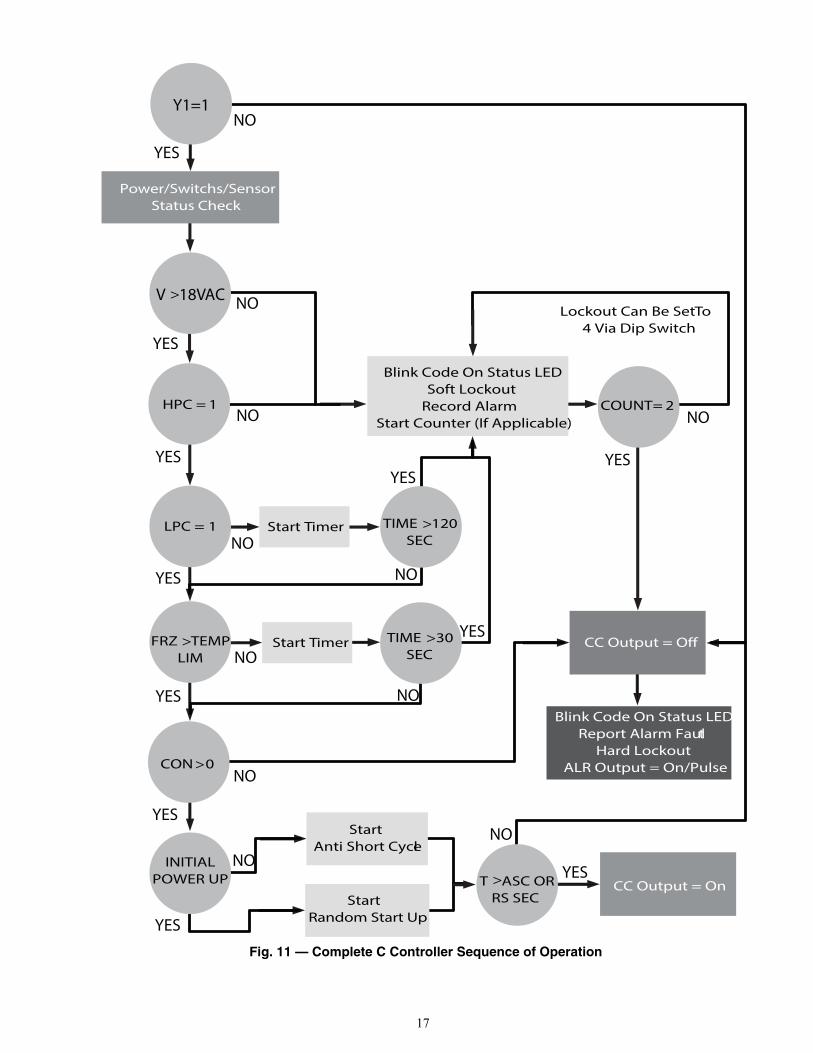
Safety Devices and the Complete C Control-ler — Each unit is factory provided with a Complete C con-troller that controls the compressor operation and monitors thesafety controls that protect the unit. See Fig. 11 for Complete Csequence of operation.
Safety controls include the following:• For single compressor models (025-071, 180 and 210),
Fig. 7 and Fig. 9- High-pressure switch inputs are wired across the HPC ter-
minals on the control board- Low-pressure switch inputs are wired across the LPC ter-
minals on the control board- The standard source side freeze thermistor is wired across
the FREEZE 1 terminals on the control board. Cutting theFREEZE 1 diode will change the freeze setting to 15 F forthe source sensor.
- The standard load side freeze thermistor is wired acrossthe FREEZE 2 terminals on the control board. Cutting theFREEZE 2 diode will change the freeze setting to 15 F forthe load sensor.
• For dual compressor models (122, 240-420), Fig. 8 andFig. 10- High-pressure switch inputs are wired across the HP1 and
HP2 terminals on the control board- Low-pressure switch inputs are wired across the LP1 and
LP2 terminals on the control board- The standard source side freeze thermister is wired across
the FREEZE 1 terminals on the control board. Cutting theJP 1 diode will change the freeze setting to 15 F for thesource sensor.
- The standard load side freeze thermister is wired across theFREEZE 2 terminals on the control board. Cutting the JP2 diode will change the freeze setting to 15 F for the loadsensor.
• Optional freeze protection sensor, mounted close to con-densing water coil, monitors refrigerant temperaturebetween condensing water coil and thermal expansionvalve. If temperature drops below or remains at freezelimit trip for 30 seconds, the controller will shut downthe compressor and enter into a soft lockout condition.The default freeze limit trip is 30 F, however this can bechanged to 15 F by cutting the R-42 resistor located ontop of DIP switch SW1.
• The optional condensate overflow protection sensor islocated in the drain pan of the unit and connected to the‘COND’ terminal on the Complete C board.
NOTE: If freeze protection sensor is not installed, a jumperbetween freeze contacts must be installed on the Complete Cboard otherwise unit will not start.
The Complete C controller includes the following features:ANTI-SHORT CYCLE TIMER — A 5-minute delay onbreak timer prevents compressor short cycling.RANDOM START — Each controller has a unique randomstart delay ranging from 270 to 300 seconds to reduce thechances of multiple units simultaneously starting after initialpower up or after a power interruption, creating a large electri-cal spike.LOW PRESSURE BYPASS TIMER — If the compressor isrunning and the low-pressure switch opens, then the controlwill keep the compressor on for 120 seconds. After 2 minutes ifthe low-pressure switch remains open, the control will shutdown the compressor and enter a soft lockout. The compressorwill not be energized until the low-pressure switch closes andthe anti-short cycle time delay expires. If the low-pressureswitch opens 2 to 4 times in 1 hour, the unit will enter a hardlockout and need to be reset.BROWNOUT/SURGE/POWER INTERRUPTION PRO-TECTION — The brownout protection in the Complete Cboard will shut down the compressor if the incoming powerfalls below 18 VAC. The compressor will remain off till thevoltage goes above 18 VAC and the anti-short cycle timer (300seconds) times out. The unit will not go into a hard lockout.MALFUNCTION OUTPUT — Alarm output is NormallyOpen (NO) dry contact. If 24 VAC output is needed R must bewired to the ALR-COM terminal; 24 VAC will be available onthe ALR-OUT terminal when the unit is in alarm condition. Ifpulse is selected the alarm output will be pulsed. The fault out-put will depend on the dip switch setting for “ALARM.” If itset to “CONST,’ a constant signal will be produced to indicatea fault has occurred and the unit requires inspection to deter-mine the type of fault. If it is set to “PULSE,” a pulse signal isproduced and a fault code is detected by a remote device indi-cating the fault. See LED Fault Indication below for blink codeexplanations. The remote device must have a malfunction de-tection capability when the Complete C board is set to“PULSE.”TEST DIP SWITCH — A test DIP switch is provided to re-duce all time delay settings to 10 seconds during troubleshoot-ing or verification of unit operation. Note that operation of theunit while in test mode can lead to accelerated wear and prema-ture failure of the unit. The “TEST” switch must be set back to“NO” for normal operation.FREEZE SENSOR — The freeze sensor input is active all thetime, if a freeze option is not selected the freeze terminals willneed a jumper. There are 2 configurable freeze points, 30 F and15 F. The unit will enter a soft lockout until the temperatureclimbs above the set point and the anti-short cycle time delayhas expired. The freeze sensor will shut the compressor outputdown after 90 seconds of water flow loss and report a freezecondition. It is recommended to have a flow switch to preventthe unit from running if water flow is lost. See Fig. 12.
IMPORTANT: Jumpers and DIP switches should onlybe clipped when power to control board has been turnedoff.
17
YES
YES
YES
YES
YES
YES
YES
YES
YES
YES YES
NO
NO
NO
NO
NO
NO
NO
NO
NO
NO
NO
Y1=1
V > 18VAC
HPC = 1
LPC = 1
FRZ > TEMPLIM
CON > 0
INITIALPOWER UP T > ASC OR
RS SEC
TIME > 30SEC
TIME > 120SEC
COUNT = 2
Start Timer
Start Timer
CC Output = On
CC Output = Off
Blink Code On Status LEDReport Alarm Fault
Hard LockoutALR Output = On/Pulse
Blink Code On Status LEDSoft Lockout
Record Alarm Start Counter (If Applicable)
Start Anti Short Cycle
Start Random Start Up
Lockout Can Be Set To 4 Via Dip Switch
Power/Switchs/SensorStatus Check
Fig. 11 — Complete C Controller Sequence of Operation

18
NOTE: If unit is employing a fresh water system (no anti-freeze protection), it is extremely important to have the“Freeze” jumper R-42 resistor set to 30 F in order to shut downthe unit at the appropriate leaving water temperature and pro-tect the heat pump from freezing if a freeze sensor is included.
LED FAULT INDICATION — Two LED indicators are pro-vided:Green: Power LED indicates 18 to 30 VAC present at theboard.Red: Fault indicator with blink codes as follows:• One blink—High pressure lockout• Two blinks—Low pressure lockout• Three blinks—Freeze sensor lockout• Four blinks—Condensate overflow• Five blinks—BrownoutINTELLIGENT RESET — If a fault condition is initiated,the 5-minute delay on break time period is initiated and the unitwill restart after these delays expire. During this period thefault LED will indicate the cause of the fault. If the fault condi-tion still exists or occurs 2 or 4 times (depending on 2 or 4 set-ting for Lockout DIP switch) before 60 minutes, the unit willgo into a hard lockout and requires a manual lockout reset. A
single condensate overflow fault will cause the unit to go into ahard lockout immediately, and will require a manual lockoutreset.LOCKOUT RESET — A hard lockout can be reset by turn-ing the unit thermostat off and then back on when the “RE-SET” DIP switch is set to “Y” or by shutting off unit power atthe circuit breaker when the “RESET” DIP switch is set to “R.”NOTE: The blower motor will remain active during a lockoutcondition.COMPLETE C BOARD DEFAULT SETTINGS — TheComplete C board will come from the factory with the follow-ing default settings:
• Freeze—“Terminals not jumped” on all the time• Temp—30°F• Lockout—2• Reset—Y• Alarm—PULSE• Test—NO• Dry Contact—Normally Open (NO)
CONSIDERATIONS1. Always check incoming line voltage power supply and
secondary control voltage for adequacy. Transformer pri-maries are dual tapped for 208 and 230 volts. Connect theappropriate tap to ensure a minimum of 18 volts second-ary control voltage. 24 volts is ideal for best operation.
2. Long length thermostat and control wiring leads may cre-ate voltage drop. Increase wire gage or up-size transform-ers may be required to ensure minimum secondary volt-age supply.
3. Carrier recommends the following guidelines for wiringbetween a thermostat and the unit: 18 GA up to 60 ft, 16GA up to 100 ft and 14 GA up to 140 ft.
4. Do not apply additional control devices to the control cir-cuit power supply without consulting the factory. Doingso may void equipment warranties.
5. Check with all code authorities on requirements involv-ing condensate disposal/over flow protection criteria.
Table 5 — Cooling Mode Operating Pressure (psig)
Table 6 — Heating Mode Operating Pressure (psig)
Freeze Protection Sensor
Fig. 12 — Freeze Protection Sensor
ENTERING LOAD/EVAP TEMP (F)
ENTERING SOURCE CONDENSER TEMPERATURE (F)75 F 85 F 95 F
Suction Pressure
Discharge Pressure
Suction Pressure
DischargePressure
Suction Pressure
Discharge Pressure
65 99-116 290-320 107-123 325-358 107-123 370-40055 91-107 265-311 91-107 303-350 99-116 370-40045 76- 91 265-311 76- 91 295-345 83- 99 358-390
ENTERING LOAD TEMP (F)
ENTERING SOURCE CONDENSER TEMPERATURE (F)40 F 60 F 80 F
Suction Pressure
Discharge Pressure
Suction Pressure
DischargePressure
Suction Pressure
Discharge Pressure
70 68-83 255-290 99-116 270-305 130-145 290-32590 76-91 350-380 99-116 358-390 130-165 370-400
110 76-91 455-480 99-116 470-500 139-165 480-575

19
START-UPUse the procedure outlined below to initiate proper unit
start-up.NOTE: This equipment is designed for indoor installationonly.
Operating Limits (See Table 7)ENVIRONMENT — This equipment is designed for indoorinstallation ONLY. Extreme variations in temperature, humidi-ty and corrosive water or air will adversely affect the unit per-formance, reliability and service life.POWER SUPPLY — A voltage variation of ± 10% of name-plate utilization voltage is acceptable.NOTE: These operating conditions are not normal or continu-ous operating conditions. It is assumed that start-up is for thepurpose of bringing the building space up to occupancytemperature.
Table 7 — 50PSW Unit Operating Limits
Unit Start-Up1. Set the primary controller to the highest setting.2. Set the primary controller system switch to “COOL.” The
reversing valve solenoid should energize. The compres-sor should not run.
3. Reduce the primary controller setting approximately 5degrees below return fluid temperature.
4. Verify the heat pump is operating in the cooling mode.5. Check the cooling refrigerant pressures against the values
listed in Table 5.6. Turn the primary controller system switch to the “OFF”
position. The unit should stop running and the reversingvalve should de-energize.
7. Leave the unit off for approximately (5) minutes to allowfor system equalization.
8. Turn the primary controller to the lowest setting.9. Set the primary controller switch to “HEAT.”
10. Increase the primary controller setting approximately 5degrees above the return fluid temperature.
11. Verify the heat pump is operating in the heating mode.12. Check the heating refrigerant pressures against the values
listed in Table 6.13. Set the primary controller to maintain the desired return
fluid temperature.14. Check for vibrations, leaks, etc.15. Instruct the owner on the unit and control operation.
Scroll Compressor Rotation — It is important to becertain compressor is rotating in the proper direction. Todetermine whether or not compressor is rotating in the properdirection:
1. Connect service gages to suction and discharge pressurefittings.
2. Energize the compressor.3. The suction pressure should drop and the discharge
pressure should rise, as is normal on any start-up.If the suction pressure does not drop and the discharge
pressure does not rise to normal levels:1. Turn off power to the unit. Install disconnect tag.2. Reverse any two of the unit power leads.3. Reapply power to the unit and verify pressures are cor-
rect. The suction and discharge pressure levels shouldnow move to their normal start-up levels.
After a few minutes of reverse operation, the scroll com-pressor internal overload protection will open, thus activatingthe unit lockout. This requires a manual reset. To reset, turn thethermostat on and then off.NOTE: There is a 5-minute time delay before the compressorwill start.
Cleaning and Flushing — Cleaning and flushing ofthe piping system is the single most important step to ensureproper start-up and continued efficient operation of the system.
Follow the instructions below to properly clean and flushthe system:
1. Verify electrical power to the unit is disconnected andlockout tag installed.
2. Install the system with the supply hose connected directlyto the return riser valve. Use a single length of flexiblehose.
3. Open all air vents. Fill the system with the water. DONOT allow system to overflow. Bleed all air from thesystem. Pressurize and check the system for leaks and re-pair appropriately.
4. Verify all strainers are in place. Start the pumps, and sys-tematically check each vent to ensure all air is bled fromthe system.
5. Verify make-up water is available. Adjust make-up waterappropriately to replace the air which was bled from thesystem. Check and adjust the water/air level in the expan-sion tank.
6. Raise the loop temperature to approximately 85F. Openthe drain at the lowest point in the system. Adjust themake-up water replacement rate to equal the rate of bleed.
7. Refill the system and add trisodium phosphate in a pro-portion of approximately one pound per 150 gal. of water(or other equivalent approved cleaning agent).
WARNING
When the disconnect switch is closed, high voltage is pres-ent in some areas of the electrical panel. Exercise cautionwhen working with the energized equipment.
WATER LIMITS COOLING(F)
HEATING(F)
SOURCE COILMin Entering Water 50 20Normal Entering Water 85 60Max Entering Water 110 70
LOAD COILMin Entering Water 50 60Normal Entering Water 60 100Max Entering Water 90 120
CAUTION
When the compressor is rotating in the wrong direction, theunit makes an elevated level of noise and does not providecooling. Damage to compressor will occur if allowed tooperate in this manner.
WARNING
To avoid possible injury or death due to electrical shock,open the power supply disconnect switch and secure it inan open position before flushing system. Install lockouttag.

20
Raise the loop temperature to 100F. Circulate the solu-tion for a minimum of 8 to 24 hours. At the end of thisperiod, shut off the circulating pump and drain the solu-tion. Repeat system cleaning if desired.
8. When the cleaning process is complete, remove the short-circuited hose. Reconnect the hoses to the proper supply,and return the connections to each of the units. Refill thesystem and bleed off all air.
9. Test the system pH with litmus paper. The system watershould be slightly alkaline (pH of 7.5 to 8.5). Add chemi-cals, as appropriate, to maintain acidity levels.
10. When the system is successfully cleaned, flushed, refilledand bled, restore power.
11. Check the main system panels, safety cutouts and alarms.Set the controls to properly maintain loop temperatures.
Antifreeze — In areas where entering loop temperaturesdrop below 40 F or where piping will be routed through areassubject to freezing, antifreeze is needed.
Alcohols and glycols are commonly used as antifreezeagents. Freeze protection should be maintained to 15 F belowthe lowest expected entering loop temperature. For example, ifthe lowest expected entering loop temperature is 30 F, the leav-ing loop temperature would be 22 to 25 F. Therefore, the freezeprotection should be at 15 F (30 F – 15 F = 15 F).
Calculate the total volume of fluid in the piping system. SeeTable 8. Use the percentage by volume in Table 9 to determinethe amount of antifreeze to use. Antifreeze concentrationshould be checked from a well mixed sample using a hydrome-ter to measure specific gravity. FREEZE PROTECTION SELECTION — The freeze sensorinput is active all the time, if a freeze option is not selected thefreeze terminals will need a jumper. There are 2 configurablefreeze points, 30 F and 15 F. The unit will enter a soft lockoutuntil the temperature climbs above the set point and the anti-short cycle time delay has expired. The freeze sensor will shutthe compressor output down after 90 seconds of water flowloss and report a freeze condition. It is recommended to have aflow switch to prevent the unit from running if water flow islost.
Table 8 — Approximate Fluid Volume (gal.)per 100 Ft of Pipe
LEGEND
NOTE: Volume of heat exchanger is approximately 1.0 gallon.
Table 9 — Antifreeze Percentages by Volume
Cooling Tower/Boiler Systems — These systemstypically use a common loop maintained at 60 to 90 F. The useof a closed circuit evaporative cooling tower with a secondaryheat exchanger between the tower and the water loop is recom-mended. If an open type cooling tower is used continuously,chemical treatment and filtering will be necessary.
Ground Coupled, Closed Loop and PlateframeHeat Exchanger Well Systems — These systems al-low water temperatures from 30 to 110 F. The external loopfield is divided up into 2 in. polyethylene supply and returnlines. Each line has valves connected in such a way that uponsystem start-up, each line can be isolated for flushing usingonly the system pumps. Air separation should be located in thepiping system prior to the fluid re-entering the loop field.
OPERATION
Power Up Mode — The unit will not operate until all theinputs, terminals and safety controls are checked for normaloperation.NOTE: The compressor will have a 5-minute anti-short cycleupon power up.
Units with Aquazone™ Complete C Con-trol — The controller will memorize the last mode used be-fore power is removed and will run in that mode after it isturned on. In all modes the control will display temperature de-gree differential setting for 5 seconds once it is powered andthis setting may be adjusted during this time. Thereafter thedisplay will switch to the monitored water temperature. Whenswitching from one mode to another the set point (the decimalpoint is used to distinguish it from water temperature) for thenew mode is displayed for 5 seconds and then monitored watertemperature. During this time the set point may be adjusted.
Off Mode — In the OFF mode all outputs are disabled andmode indication LED’s will be off.
The control will first display temperature differential settingwith the ability for the user to adjust it and then will display“OFF” and finally water temperature.
CAUTION
To avoid possible damage to a plastic (PVC) piping sys-tem, do not allow temperatures to exceed 110 F.
CAUTION
DO NOT use “Stop Leak” or any similar chemical agent inthis system. Addition of these chemicals to the loop waterwill foul the system and inhibit unit operation.
IMPORTANT: All alcohols should be pre-mixed andpumped from a reservoir outside of the building orintroduced under water level to prevent alcohols fromfuming.
PIPE DIAMETER (in.) VOLUME (gal.)Copper 1 4.1
1.25 6.41.5 9.2
Rubber Hose 1 3.9Polyethylene 3/4 IPS SDR11 2.8
1 IPS SDR11 4.511/4 IPS SDR11 8.01/2 IPS SDR11 10.92 IPS SDR11 18.011/4 IPS SCH40 8.311/2 IPS SCH40 10.92 IPS SCH40 17.0
IPS — Internal Pipe SizeSCH — ScheduleSDR — Standard Dimensional Ratio
ANTIFREEZEMINIMUM TEMPERATURE FOR
FREEZE PROTECTION (F)10 15 20 25
Methanol (%) 25 21 16 10100% USP Food GradePropylene Glycol (%) 38 30 22 15

21
Heating Mode — When the unit is operated in the heatingmode and the controlled water temperature is below the setpoint minus the differential setting, terminal Y1 will close andthe unit will operate (first stage compressor in a two stage unit).When the set point is satisfied the compressor is turned off.
In a two-stage unit after the first stage activation if the watertemperature drops an additional 2 degrees below the set point,the second stage (terminal Y2) will be activated (if control isconfigured for both compressors). Both stages will be on untilthe set point is satisfied.
When the unit runs after power is applied or the mode ischanged from cooling to heating, if the fluid temperature is be-low set point and does not change for 3 minutes, the secondstage of heating will be activated. This only applies for a two-stage machine.
There will be 5 minutes delay on break after the unit cyclesoff on temperature, a power interruption or because of a faultcondition. See Table 10.
At any point in time the control will ignore a low pressureswitch condition for 120 seconds before turning off the com-pressor.
Table 10 — Fault Codes
Cooling Mode — When the unit is operated in the cool-ing mode and the leaving water temperature is above the tem-perature set point plus the differential setting, terminals Y1 willclose (first-stage compressor of a two-stage unit) and the unitwill operate in the cooling mode. When the set point is satisfiedthe compressor is turned off. The reversing valve is always ac-tivated when the unit is in the cooling mode.
On two-stage units, after first stage activation if water tem-perature increases 2 degrees above the set point, the secondstage (terminal Y2) will be activated (if control is configuredfor both compressors). Both stages will remain on until the setpoint is satisfied.
When the unit runs after power is applied or the mode ischanged from heating to cooling, if the fluid temperature isabove cooling point and does not change for 3 minutes, the sec-ond stage will be activated. This only applies for a two-stagemachine.
There will be 5 minutes delay on break after the unit cyclesoff on temperature, a power interruption or because of a faultcondition.
Retry Mode — In Retry mode, the staus LED will flashthe code for the corresponding fault. If the fault clears and the
thermostat call (Y) is still present the Complete C or Deluxe Dcontrol will run the compressor once the ASC (anti-short cycle)timer has expired and will try to satisfy the call. If the call issatisfied, the unit will resume its normal operation.
If 2 or 4 consecutive faults occur (depending on the DIPswitch setting) within 1 hour, the controller will lock the com-pressor operation out and will flash the alarm code on the statusLED as well as alarm dry contact output. When the CompleteC or Deluxe D control enters lockout mode, the alarm will alsobe shown on the panel mounted LED.
SERVICEPerform the procedures outlined below periodically, as
indicated.
Water Coil — Keep all air out of the water coil. Checkopen loop systems to be sure the well head is not allowing airto infiltrate the water line. Always keep lines airtight.
Inspect heat exchangers regularly, and clean more frequent-ly if the unit is located in a “dirty” environment. The heatexchanger should be kept full of water at all times. Open loopsystems should have an inverted P trap placed in the dischargeline to keep water in the heat exchanger during off cycles.Closed loop systems must have a minimum of 15 psig duringthe summer and 40 psig during the winter.
Check P trap frequently for proper operation.
Refrigerant System — Verify air and water flow ratesare at proper levels before servicing. To maintain sealed circuit-ry integrity, do not install service gages unless unit operationappears abnormal.
BLINK CODE
SINGLE COMPRESSOR
SIZES 025-071, 180, AND 210
DUAL COMPRESSOR
SIZES 122, 240-420
One Blink High Pressure High Pressure 1Two Blinks Low Pressure Low Pressure 1Three Blinks Source Side Freeze High Pressure 2Four Blinks Not Used on PSW Low Pressure 2Five Blinks Brown Out Freeze (Load or
Source)Six Blinks Load Side Freeze Not Used on
These SizesSeven Blinks Not Used on
These SizesBrown Out
IMPORTANT: When a compressor is removed from thisunit, system refrigerant circuit oil will remain in the com-pressor. To avoid leakage of compressor oil, the refrigerantlines of the compressor must be sealed after it is removed.
IMPORTANT: To avoid the release of refrigerant into theatmosphere, the refrigerant circuit of this unit must only beserviced by technicians which meet local, state and federalproficiency requirements.
IMPORTANT: All refrigerant discharged from this unitmust be recovered without exception. Technicians must fol-low industry accepted guidelines and all local, state and fed-eral statutes for the recovery and disposal of refrigerants.
WARNING
To prevent injury or death due to electrical shock or contactwith moving parts, open unit disconnect switch before ser-vicing unit.
CAUTION
To avoid fouled machinery and extensive unit clean-up,DO NOT operate units without filters in place. DO NOTuse equipment as a temporary heat source duringconstruction.

22
Condenser Cleaning — Water-cooled condensers mayrequire cleaning of scale (water deposits) due to improperlymaintained closed-loop water systems. Sludge build-up mayneed to be cleaned in an open water tower system due toinduced contaminants.
Local water conditions may cause excessive fouling orpitting of tubes. Condenser tubes should therefore be cleaned atleast once a year, or more often if the water is contaminated.
Proper water treatment can minimize tube fouling andpitting. If such conditions are anticipated, water treatmentanalysis is recommended. Refer to the Carrier System DesignManual, Part 5, for general water conditioning information.
Clean condensers with an inhibited hydrochloric acid solu-tion. The acid can stain hands and clothing, damage concrete,and, without inhibitor, damage steel. Cover surroundings toguard against splashing. Vapors from vent pipe are not harmful,but take care to prevent liquid from being carried over by thegases.
Warm solution acts faster, but cold solution is just as effec-tive if applied for a longer period.
GRAVITY FLOW METHOD — Do not add solution fasterthan vent can exhaust the generated gases.
When condenser is full, allow solution to remain overnight,then drain condenser and flush with clean water. Follow acidmanufacturer’s instructions. See Fig. 13.
FORCED CIRCULATION METHOD — Fully open ventpipe when filling condenser. The vent may be closed whencondenser is full and pump is operating. See Fig. 14.
Regulate flow to condenser with a supply line valve. Ifpump is a nonoverloading type, the valve may be fully closedwhile pump is running.
For average scale deposit, allow solution to remain in con-denser overnight. For heavy scale deposit, allow 24 hours.Drain condenser and flush with clean water. Follow acid manu-facturer’s instructions.
Checking System Charge — Units are shipped withfull operating charge. If recharging is necessary:
1. Insert thermometer bulb in insulating rubber sleeve onliquid line near filter drier. Use a digital thermometer forall temperature measurements. DO NOT use a mercuryor dial-type thermometer.
2. Connect pressure gage to discharge line near compressor.3. After unit conditions have stabilized, read head pressure
on discharge line gage.NOTE: Operate unit a minimum of 15 minutes beforechecking charge. From standard field-supplied Pressure-Temperature chart for R-410A, find equivalent saturatedcondensing temperature.
4. Read liquid line temperature on thermometer; thensubtract from saturated condensing temperature. The dif-ference equals subcooling temperature.
Refrigerant Charging
NOTE: Do not vent or depressurize unit refrigerant to atmo-sphere. Remove and recover refrigerant following acceptedpractices.
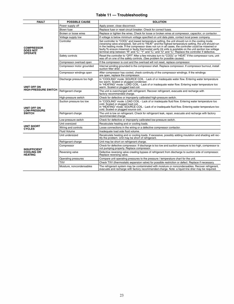
TROUBLESHOOTINGWhen troubleshooting problems with a WSHP, refer to
Table 11.
CAUTION
Follow all safety codes. Wear safety glasses and rubbergloves when using inhibited hydrochloric acid solution.Observe and follow acid manufacturer’s instructions.
Fig. 13 — Gravity Flow Method
FILL CONDENSER WITHCLEANING SOLUTION. DONOT ADD SOLUTIONMORE RAPIDLY THANVENT CAN EXHAUSTGASES CAUSED BYCHEMICAL ACTION.
PAIL
FUNNEL
CONDENSER
PAIL
3’ TO 4’
VENTPIPE 5’ APPROX
1”PIPE
WARNING
To prevent personal injury, wear safety glasses and gloveswhen handling refrigerant. Do not overcharge system —this can cause compressor flooding.
SUCTION
PUMPSUPPORT
TANK
FINE MESHSCREEN
RETURN
GAS VENTPUMP PRIMINGCONN.
GLOBEVALVES
SUPPLY
1” PIPE
CONDENSER
REMOVE WATERREGULATING VALVE
Fig. 14 — Forced Circulation Method
23
Table 11 — Troubleshooting
FAULT POSSIBLE CAUSE SOLUTION
COMPRESSORDOES NOTOPERATE
Power supply off Apply power, close disconnect.Blown fuse Replace fuse or reset circuit breaker. Check for correct fuses.Broken or loose wires Replace or tighten the wires. Check for loose or broken wires at compressor, capacitor, or contactor.Voltage supply low If voltage is below minimum voltage specified on unit data plate, contact local power company.Controller Set controller to “COOL” and lowest temperature setting, the unit should run in the cooling mode
(reversing valve energized). Set unit to “HEAT” and the highest temperature setting, the unit should run in the heating mode. If the compressor does not run in all cases, the controller could be miswired or faulty.To ensure miswired or faulty thermostat verify 24 volts is available on the unit section low voltage terminal strip between “R” and “C,” “Y” and “C,” and “O” and “C.” Replace the controller if defective.
Safety controls Reset the controller to “OFF.” After a few minutes turn to “COOL” or “HEAT.” If the compressor runs, unit was off on one of the safety controls. (See problem for possible causes)
Compressor overload open If the compressor is cool and the overload will not reset, replace compressor.Compressor motor grounded Internal winding grounded to the compressor shell. Replace compressor. If compressor burnout, install
suction filter drier.Compressor windings open After compressor has cooled, check continuity of the compressor windings. If the windings
are open, replace the compressor.
UNIT OFF ONHIGH-PRESSURE SWITCH
Discharge pressure too high In “COOLING” mode: SOURCE COIL - Lack of or inadequate water flow. Entering water temperature too warm. Scaled or plugged condenser.In “HEATING” mode: LOAD COIL - Lack of or inadequate water flow. Entering water temperature too warm. Scaled or plugged load coil.
Refrigerant charge The unit is overcharged with refrigerant. Recover refrigerant, evacuate and recharge withfactory recommended charge.
High-pressure switch Check for defective or improperly calibrated high-pressure switch.
UNIT OFF ONLOW-PRESSURESWITCH
Suction pressure too low In “COOLING” mode: LOAD COIL - Lack of or inadequate fluid flow. Entering water temperature too cold. Scaled or plugged load coil.In “HEATING” mode: SOURCE COIL - Lack of or inadequate fluid flow. Entering water temperature too cold. Scaled or plugged source coil.
Refrigerant charge The unit is low on refrigerant. Check for refrigerant leak, repair, evacuate and recharge with factory recommended charge.
Low-pressure switch Check for defective or improperly calibrated low-pressure switch.
UNIT SHORTCYCLES
Unit oversized Recalculate heating and or cooling loads.Wiring and controls Loose connections in the wiring or a defective compressor contactor.Fluid Volume Inadequate load side fluid volume.
INSUFFICIENTCOOLING ORHEATING
Unit undersized Recalculate heating and or cooling loads. If excessive, possibly adding insulation and shading will rec-tify the problem. Unit may be short of refrigerant.
Refrigerant charge Unit may be short on refrigerant charge.Compressor Check for defective compressor. If discharge is too low and suction pressure is too high, compressor is
not pumping properly. Replace compressor.Reversing valve Defective reversing valve creating bypass of refrigerant from discharge to suction side of compressor.
Replace reversing valve.Operating pressures Compare unit operating pressures to the pressure / temperature chart for the unit.TXV Check TXV (thermostatic expansion valve) for possible restriction or defect. Replace if necessary.Moisture, noncondensables The refrigerant system may be contaminated with moisture or noncondensables. Recover refrigerant,
evacuate and recharge with factory recommended charge. Note: a liquid line drier may be required.


Manufacturer reserves the right to discontinue, or change at any time, specifications or designs without notice and without incurring obligations.Catalog No. 04-53500103-01 Printed in U.S.A. Form 50PSW-3SI Pg 26 8-14 Replaces: NEW
© Carrier Corporation 2014 8733937867

Manufacturer reserves the right to discontinue, or change at any time, specifications or designs without notice and without incurring obligations.Catalog No. 04-53500103-01 Printed in U.S.A. Form 50PSW-3SI CL-1 8-14 Replaces: NEW
50PSW START-UP CHECKLIST
CUSTOMER:___________________________ JOB NAME:
MODEL NO.:___________________________ SERIAL NO.:______________ DATE:
LOOP TYPE:___________________________ ANTIFREEZE TYPE AND %:______________________
I. PRE-START-UP
DOES THE UNIT VOLTAGE CORRESPOND WITH THE SUPPLY VOLTAGE AVAILABLE? (Y/N)
HAVE THE POWER AND CONTROL WIRING CONNECTIONS BEEN MADE AND TERMINALS TIGHT? (Y/N)
HAVE WATER CONNECTIONS BEEN MADE AND IS FLUID AVAILABLE AT HEAT EXCHANGER?(Y/N)
HAS PUMP BEEN TURNED ON AND ARE ISOLATION VALVES OPEN? (Y/N)
HAS CONDENSATE CONNECTION BEEN MADE AND IS A TRAP INSTALLED? (Y/N)
IS AN AIR FILTER INSTALLED? (Y/N)
II. START-UP
IS FAN OPERATING WHEN COMPRESSOR OPERATES? (Y/N)
IF 3-PHASE SCROLL COMPRESSOR IS PRESENT, VERIFY PROPER ROTATION PER INSTRUCTIONS.(Y/N)
UNIT VOLTAGE — COOLING OPERATION
PHASE AB VOLTS PHASE BC VOLTS PHASE CA VOLTS(if 3 phase) (if 3 phase)
PHASE AB AMPS PHASE BC AMPS PHASE CA AMPS (if 3 phase) (if 3 phase)
CONTROL VOLTAGE
IS CONTROL VOLTAGE ABOVE 21.6 VOLTS? (Y/N) .IF NOT, CHECK FOR PROPER TRANSFORMER CONNECTION.
TEMPERATURES
FILL IN THE ANALYSIS CHART ATTACHED.
COAXIAL HEATEXCHANGER
COOLING CYCLE:FLUID IN F FLUID OUT F PSI FLOW
HEATING CYCLE:FLUID IN F FLUID OUT F PSI FLOW
AIR COIL COOLING CYCLE:AIR IN F AIR OUT F
HEATING CYCLE:AIR IN F AIR OUT F

Manufacturer reserves the right to discontinue, or change at any time, specifications or designs without notice and without incurring obligations.Catalog No. 04-53500103-01 Printed in U.S.A. Form 50PSW-3SI CL-2 8-14 Replaces: NEW
© Carrier Corporation 2014
- -
- -
- -
- -
- -
- -
- -
- -
- -
- -
- -
- -
- -
- -
- -
- -
- -
- -
- -
- -
- -
- -
- -
- -
- -
- -
- -
- -
- -
- -
- -
- -
- -
- -
- -
- -
- -
- -
- -
- -
- -
- -
- -
- -
- -
- -
- -
- -
- -
- -
- -
- -
- -
- -
- -
- -
- -
- -
- -
- -
- -
- -
- -
- -
- -
- -
- -
- -
- -
- -
- -
- -
- -
- -
- -
- -
- -
- -
- -
- -
- -
- -
- -
- -
- -
- -
- --
- -
- -
- -
- -
- -
- -
- -
- -
- -
-
CU
T A
LON
G D
OT
TE
D L
INE
CU
T A
LON
G D
OT
TE
D L
INE
8733937867
HEATING AND COOLING CYCLE ANALYSIS
HEAT OF EXTRACTION (ABSORPTION) OR HEAT OF REJECTION =
FLOW RATE (GPM) x TEMP. DIFF. (DEG. F) x FLUID FACTOR* =(Btu/hr)
SUPERHEAT = SUCTION TEMPERATURE – SUCTION SATURATION TEMPERATURE= (DEG F)
SUBCOOLING = DISCHARGE SATURATION TEMPERATURE – LIQUID LINE TEMPERATURE= (DEG F)
*Use 500 for water, 485 for antifreeze.
DESCRIPTION HEATING COOLING NOTESVoltageCompressor Amp
1 Suction Temperature2 Suction Pressure
2a Saturation Temperature2b Superheat3 Discharge Temperature4 Discharge Pressure
4a Saturation Temperature4b Subcooling5 Liquid Line Temperature6 Source Water In Temperature7 Source Water Out Temperature Temperature Difference —8 Source Water In Pressure9 Source Water Out Pressure
9a Pressure Drop9b Flow Rate (gpm)10 Load Water In Temperature11 Load Water Out Temperature Temperature Difference —12 Load Water In Pressure13 Load Water Out Pressure
13a Pressure Drop13b Flow Rate (gpm)
COMPRESSOR
DISCHARGE
SUCTION
HWG*
EXPANSIONVALVE FILTER
DRIER
REVERSINGVALVE
HEATING POSITION COOLING POSITION
1
COAX
CO
AX
5
1210
1311
9
7
8
6
4
3
2
FP2:HEATINGLIQUIDLINE
5 FP1:COOLINGLIQUIDLINE
CONDENSER (HTG)EVAPORATOR (CLG)
CONDENSER (COOLING)EVAPORATOR (HEATING)
WATER-TO-WATER UNITS REFRIG FLOW - HEATING REFRIG FLOW - COOLING
Source
Load
LEGEND
*Turn off HWG (hot water generator)before troubleshooting.
CLG — CoolingHTG — Heating
a50-8465