Embed Size (px)
Citation preview
Installation, Start-Up andService Instructions
CONTENTSPage
SAFETY CONSIDERATIONS . . . . . . . . . . . . . . . . . . . 1INSTALLATION . . . . . . . . . . . . . . . . . . . . . . . . . . . . .1-28Step 1 — Provide Unit Support . . . . . . . . . . . . . . . 1• ROOF CURB• SLAB MOUNTStep 2 — Field Fabricate Ductwork . . . . . . . . . . . . 1Step 3 — Install External Trap for CondensateDrain . . . . . . . . . . . . . . . . . . . . . . . . . . . . . . . . . . . . . . 4
Step 4 — Rig and Place Unit . . . . . . . . . . . . . . . . . . 4• POSITIONINGStep 5 — Make Electrical Connections . . . . . . . . 9• DISCONNECT BOX LOCATION• FIELD POWER SUPPLY• FIELD CONTROL WIRING• HEAT ANTICIPATOR SETTING FOR ACCESSORYELECTRIC HEATERS
Step 6 — Adjust Factory-Installed Options . . . 13• APOLLO CONTROL• MANUAL OUTDOOR-AIR DAMPER• OPTIONAL DURABLADE ECONOMIZERStep 7 — Adjust Evaporator-Fan Speed . . . . . . 19START-UP . . . . . . . . . . . . . . . . . . . . . . . . . . . . . . . . .29,30SERVICE . . . . . . . . . . . . . . . . . . . . . . . . . . . . . . . . . .30-35TROUBLESHOOTING . . . . . . . . . . . . . . . . . . . . . . . . 36START-UP CHECKLIST . . . . . . . . . . . . . . . . . . . . .CL-1
SAFETY CONSIDERATIONSInstallation and servicing of air-conditioning equipment
can be hazardous due to system pressure and electrical com-ponents. Only trained and qualified service personnel shouldinstall, repair, or service air-conditioning equipment.Untrained personnel can perform basic maintenance func-
tions of cleaning coils and filters and replacing filters. Allother operations should be performed by trained service per-sonnel. When working on air-conditioning equipment, ob-serve precautions in the literature, tags and labels attachedto the unit, and other safety precautions that may apply.Follow all safety codes.Wear safety glasses andwork gloves.
Use quenching cloth for unbrazing operations. Have fire ex-tinguisher available for all brazing operations.
Before performing service or maintenance operations onunit, turn off main power switch to unit. Electrical shockcould cause personal injury.
INSTALLATIONUnit is shipped in the vertical configuration. To convert to
horizontal configuration, remove side duct opening covers.
Using the same screws, install covers on vertical duct open-ings with insulation-side down. Seals around duct openingsmust be tight.
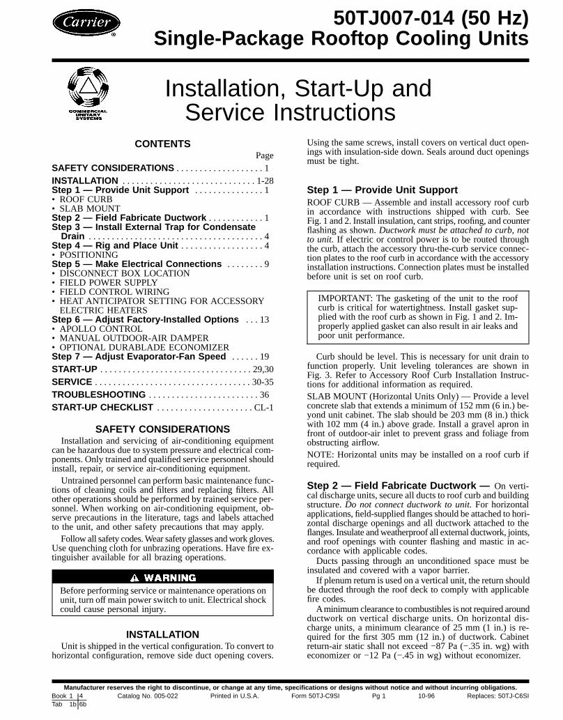
Step 1 — Provide Unit SupportROOF CURB — Assemble and install accessory roof curbin accordance with instructions shipped with curb. SeeFig. 1 and 2. Install insulation, cant strips, roofing, and counterflashing as shown.Ductwork must be attached to curb, notto unit. If electric or control power is to be routed throughthe curb, attach the accessory thru-the-curb service connec-tion plates to the roof curb in accordance with the accessoryinstallation instructions. Connection plates must be installedbefore unit is set on roof curb.
IMPORTANT: The gasketing of the unit to the roofcurb is critical for watertightness. Install gasket sup-plied with the roof curb as shown in Fig. 1 and 2. Im-properly applied gasket can also result in air leaks andpoor unit performance.
Curb should be level. This is necessary for unit drain tofunction properly. Unit leveling tolerances are shown inFig. 3. Refer to Accessory Roof Curb Installation Instruc-tions for additional information as required.SLAB MOUNT (Horizontal Units Only) — Provide a levelconcrete slab that extends a minimum of 152 mm (6 in.) be-yond unit cabinet. The slab should be 203 mm (8 in.) thickwith 102 mm (4 in.) above grade. Install a gravel apron infront of outdoor-air inlet to prevent grass and foliage fromobstructing airflow.NOTE: Horizontal units may be installed on a roof curb ifrequired.
Step 2 — Field Fabricate Ductwork — On verti-cal discharge units, secure all ducts to roof curb and buildingstructure.Do not connect ductwork to unit.For horizontalapplications, field-supplied flanges should be attached to hori-zontal discharge openings and all ductwork attached to theflanges. Insulate andweatherproof all external ductwork, joints,and roof openings with counter flashing and mastic in ac-cordance with applicable codes.Ducts passing through an unconditioned space must be
insulated and covered with a vapor barrier.If plenum return is used on a vertical unit, the return should
be ducted through the roof deck to comply with applicablefire codes.Aminimumclearance to combustibles is not required around
ductwork on vertical discharge units. On horizontal dis-charge units, a minimum clearance of 25 mm (1 in.) is re-quired for the first 305 mm (12 in.) of ductwork. Cabinetreturn-air static shall not exceed −87 Pa (−.35 in. wg) witheconomizer or −12 Pa (−.45 in wg) without economizer.
50TJ007-014 (50 Hz)Single-Package Rooftop Cooling Units
Manufacturer reserves the right to discontinue, or change at any time, specifications or designs without notice and without incurring obligations.Book 1 4Tab 1b 6b
Catalog No. 005-022 Printed in U.S.A. Form 50TJ-C9SI Pg 1 10-96 Replaces: 50TJ-C6SI
ROOF CURBACCESSORY ‘‘A’’ UNIT SIZE
CRRFCURB001A00 18-29 [356]50TJ007
CRRFCURB002A00 28-09 [610]
UNIT SIZE ‘‘B’’ ‘‘C’’‘‘D’’ ALTDRAINHOLE
POWER CONTROL CONNECTORPKG ACY
50TJ007 18-911⁄169[551]
18-49[406] 13⁄49 [45]
3⁄49 NPT 1⁄2 NPT CRBTMPWR001A00(Thru-the-bottom)
11⁄49 NPT 1⁄29 NPT CRBTMPWR002A00(Thru-the-bottom)
Fig. 1 — Roof Curb Details, 50TJ007
NOTES:1. Roof curb accessory is shipped unassembled.2. Insulated panels.3. Dimensions in [ ] are in millimeters.4. Roof curb: galvanized steel.5. Attach ductwork to curb (flanges of duct rest on curb).6. Service clearance 4 ft on each side.
7. Direction of airflow.
2

ROOF CURBACCESSORY ‘‘A’’ UNIT SIZE
CRRFCURB003A00 18-29 [356]50TJ008-014
CRRFCURB004A00 28-09 [610]
UNIT SIZE ‘‘B’’ ‘‘C’’‘‘D’’ ALTDRAINHOLE
POWER CONTROL CONNECTORPKG ACY
50TJ008-014 28-87⁄169[827]
18-1015⁄169[583] 13⁄49 [45]
3⁄49 NPT 1⁄2 NPT CRBTMPWR001A00(Thru-the-bottom)
11⁄49 NPT 1⁄29 NPT CRBTMPWR002A00(Thru-the-bottom)
NOTES:1. Roof curb accessory is shipped unassembled.2. Insulated panels.3. Dimensions in [ ] are in millimeters.4. Roof curb: galvanized steel.5. Attach ductwork to curb (flanges of duct rest on curb).6. Service clearance 4 ft on each side.7. Direction of airflow.
Fig. 2 — Roof Curb Details, 50TJ008-014
3

Step 3 — Install External Trap for CondensateDrain — The unit’s 19-mm (3⁄4-in.) condensate drain con-nections are located at the bottom and side of the unit. Unitdischarge connections do not determine the use of drain con-nections; either drain connection can be used with either ver-tical or horizontal applications.When using the standard side drain connection, make sure
the plug in the alternate bottom connection is tight beforeinstalling the unit.To use the bottom drain connection for a roof curb in-
stallation, relocate the factory-installed plug from the bot-tom connection to the side connection. See Fig. 4. The pip-ing for the condensate drain and external trap can be completedafter the unit is in place.All units must have an external trap for condensate drain-
age. Install a trap at least 100 mm (4 in.) deep and protectagainst freeze-up. See Fig. 5. If drain line is installed down-stream from the external trap, pitch the line away from theunit at 25 mm (1 in.) per 3 m (10 ft) of run. Do not use a pipesize smaller than the unit connection.
Step 4—Rig and Place Unit— Inspect unit for trans-portation damage. File any claim with transportation agency.Keep unit upright and do not drop. Spreader bars are notrequired if top crating is left on unit. Rollers may be used tomove unit across a roof. Level by using unit frame asa reference. See Tables 1A and 1B and Fig. 6 and 7 for ad-
ditional information. Operating weight is shown inTables 1A and 1B and Fig. 6 and 7.Lifting holes are provided in base rails as shown in
Fig. 8 and 9. Refer to rigging instructions on unit.
All panels must be in place when rigging.
POSITIONING—Maintain clearance around and above unitto provide proper airflow and service access. See Fig. 8and 9.Position unit on roof curb so that the following clearances
are maintained: 7 mm (1⁄4 in.) clearance between roof curband base rails on each side and front of unit: 30 mm(15⁄32 in.) clearance between roof curb and rear of unit (seeFig. 1 and 2, section C-C).Do not install unit in an indoor location. Do not locate
unit air inlet near exhaust vents or other sources of contami-nated air.Although unit is weatherproof, guard against water from
higher level runoff and overhangs.After unit is in position, remove shipping materials.
(Size 007)
(Size 008-014)
MAXIMUM ALLOWABLE DIFFERENCE
A-B B-C A-Cmm in. mm in. mm in.13 .5 25 1.0 25 1.0
Fig. 3 — Unit Leveling Tolerances
NOTE: Drain plug is shown in factory-installed position.
Fig. 4 — Condensate Drain Pan
NOTE: Trap should be deep enough to offset maximum unit staticdifference. A 100-mm (4-in.) trap is recommended.
Fig. 5 — External Trap Condensate Drain
4

NOTES:1. Dimension in ( ) is in millimeters.2. Hook rigging shackles through holes in base rail, as shown in
detail ‘‘A.’’ Holes in base rails are centered around the unit centerof gravity. Use wooden top skid, when rigging, to prevent riggingstraps from damaging unit.
3. Weights do not include economizer. See Tables 1A and 1B foreconomizer weights.
All panels must be in place when rigging.
UNITMAX
WEIGHTDIMENSIONS
‘‘A’’ ‘‘B’’ ‘‘C’’lb kg in. mm in. mm in. mm
50TJ007 470 213 73.69 1872 35 889 33.35 847
Fig. 6 — Rigging Details, 50TJ007
NOTES:1. Dimensions in ( ) are in millimeters.2. Hook rigging shackles through holes in base rail, as shown in
detail ‘‘A.’’ Holes in base rails are centered around the unit centerof gravity. Use wooden top skid when rigging to prevent riggingstraps from damaging unit.
3. Unit weights do not include economizer. See Tables 1A and 1Bfor economizer weights.
All panels must be in place when rigging.
UNITMAX
WEIGHTDIMENSIONS
‘‘A’’ ‘‘B’’ ‘‘C’’lb kg in. mm in. mm in. mm
50TJ008 755 342 77.42 1967 40.25 1022 41.31 105050TJ009 760 345 77.42 1967 40.25 1022 41.31 105050TJ012 915 415 77.42 1967 40.25 1022 49.31 125350TJ014 930 422 77.42 1967 40.25 1022 49.31 1253
Fig. 7 — Rigging Details, 50TJ008-014
5

UNIT50TJ
STD UNITWEIGHT
CORNERWEIGHT (A)
CORNERWEIGHT (B)
CORNERWEIGHT (C)
CORNERWEIGHT (D)
lb kg lb kg lb kg lb kg lb kg007 470 213 148 67 103 47 155 70 64 29
CONNECTION SIZESA 11⁄89 dia [28.6] field power supply holeB 3⁄49-14 NPT condensate drainC 13⁄89 dia [35] power supply knockoutD 29 dia [50.8] power supply knockout
BOTTOM POWER CHART, THESEHOLES REQUIRED FOR USE WITH
ACCESSORY PACKAGES —CRBTMPWR001A00 (1⁄29, 3⁄49)
ORCRBTMPWR002A00 (1⁄29, 11⁄49)
THREADEDCONDUITSIZE
WIRE USEREQUIREDHOLE SIZES
(MAX.)1⁄2( 24 V 7⁄89 [22.2]3⁄4( Power* 11⁄89 [28.4]11⁄4( Power* 13⁄49 [44.4]
*Select either 3⁄49 or 11⁄49 for power, depending on wire size.
NOTES:1. Dimensions in [ ] are in millimeters.
2. Center of gravity.
3. Direction of airflow.
4. Ductwork to be attached to accessory roof curb only.5. Minimum clearance (local codes or jurisdiction may prevail):
a. Bottom to combustible surfaces (when not using curb) 0 mm (0 in.). On horizontaldischarge units with electric heat 25 mm (1 in.) clearance to ductwork for .3 m(1 ft).
b. Condenser coil, for proper airflow, 914 mm (36 in.) one side, 304 mm (12 in.) theother. The side getting the greater clearance is optional.
c. Overhead, 1524 mm (60 in.) to assure proper condenser fan operation.d. Between units, control box side, 1067 mm (42 in.) per NEC (National Electrical
Code, U.S.A. Standard).e. Between unit and ungrounded surfaces, control box side, 914 mm (36 in.) per NEC.f. Between unit and block or concrete walls and other grounded surfaces, control
box side, 1067 mm (42 in.) per NEC.g. Horizontal supply and return end, 0 mm (0 in.).
6. With the exception of the clearances stated in Notes 5a, b, and c, a removable fenceor barricade requires no clearance.
7. Units may be installed on combustible floors made from wood or class A, B, or C roofcovering material.
8. The vertical center of gravity is 18-61⁄29 [470] up from the bottom of the base rail. Hori-zontal center of gravity is shown.
Fig. 8 — Base Unit Dimensions, 50TJ007
6
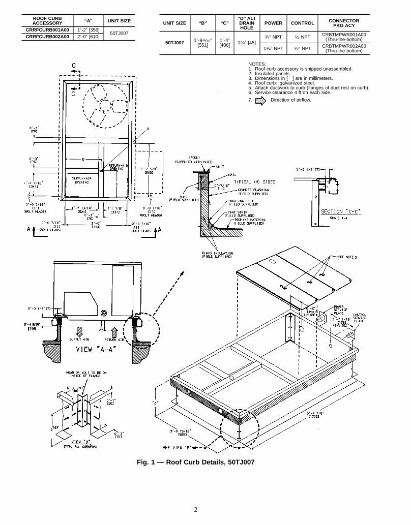
UNIT50TJ
STD UNITWEIGHT
CORNERWEIGHT (A)
CORNERWEIGHT (B)
CORNERWEIGHT (C)
CORNERWEIGHT (D) ‘‘H’’ ‘‘J’’ ‘‘K’’
lb kg lb kg lb kg lb kg lb kg ft-in. mm ft-in. mm ft-in. mm008 755 342 164 74 140 64 208 94 243 110 1-27⁄8 378 3-55⁄16 1050 2-911⁄16 856009 760 345 165 75 141 64 209 94 245 111 3-37⁄8 1013 3-55⁄16 1050 2-911⁄16 856012 915 415 199 90 170 77 252 114 294 134 2-57⁄8 759 4-15⁄16 1253 3-03⁄8 924014 930 422 202 92 172 78 256 116 300 136 1-27⁄8 378 4-15⁄16 1253 3-03⁄8 924
BOTTOM POWER CHART, THESE HOLES REQUIREDFOR USE WITH ACCESSORY PACKAGES —
CRBTMPWR001A00 (1⁄29, 3⁄49)OR
CRBTMPWR002A00 (1⁄29, 11⁄49)
THREADEDCONDUIT SIZE WIRE USE REQUIRED HOLE
SIZES (MAX.)1⁄2( 24 V 7⁄89 [22.2]3⁄4( Power* 11⁄89 [28.4]11⁄4( Power* 13⁄49 [44.4]
*Select either 3⁄49 or 11⁄49 for power, depending on wire size.
CONNECTION SIZESA 13⁄89 dia [35] field power supply holeB 21⁄29 dia [64] power supply knockoutC 13⁄49 dia [44] charging port holeD 7⁄89 [22] field control wiring holeE 23⁄49-14 NPT condensate drainF 29 dia [51] power supply knockout
NOTES:1. Dimensions in [ ] are in millimeters.
2. Center of gravity.
3. Direction of airflow.
4. Ductwork to be attached to accessory roof curb only.5. Minimum clearance (local codes or jurisdiction may prevail):
a. Bottom to combustible surfaces (when not using curb) 0 mm (0 in.). On horizontaldischarge units with electric heat 25 mm (1 in.) clearance to ductwork for .3 m (1 ft).
b. Condenser coil, for proper airflow, 914 mm (36 in.) one side, 304 mm (12 in.) theother. The side getting the greater clearance is optional.
c. Overhead, 1524 mm (60 in.) to assure proper condenser fan operation.d. Between units, control box side, 1067 mm (42 in.) per NEC (National Electrical Code,
U.S.A. Standard)).e. Between unit and ungrounded surfaces, control box side, 914 mm (36 in.) per NEC.f. Between unit and block or concrete walls and other grounded surfaces, control box
side, 1067 mm (42 in.) per NEC.g. Horizontal supply and return end, 0 mm (0 in.).
6. With the exception of the clearances stated in Notes 5a, b, and c, a removable fenceor barricade requires no clearance.
7. Units may be installed on combustible floors made from wood or class A, B, or C roofcovering material.
8. The vertical center of gravity is 18-71⁄29 [495] for 008 and 009, 28-09 [610] for 012 and014 up from the bottom of the base rail. Horizontal center of gravity is shown.
Fig. 9 — Base Unit Dimensions, 50TJ008-014
7

Table 1A — Physical Data (SI)
UNIT SIZE 007 008 009 012 014NOMINAL CAPACITY (kW) 21.1 26.4 29.9 35.2 44.0OPERATING WEIGHT (kg)Unit 213 342 345 415 422Durablade Economizer 15.4 20 20 20 20Roof Curb 52 65 65 65 65
COMPRESSOR TYPE Scroll Reciprocating Reciprocating Reciprocating ScrollQuantity 1 2 2 2 2Oil (ml) 1597 1479 ea 1479 ea 1479 ea 1597 ea
REFRIGERANT TYPE R-22Operating Charge (kg)Circuit 1 3.22 2.10 2.54 2.49 3.49Circuit 2 — 2.13 2.54 2.55 3.40
CONDENSER COIL Enhanced Copper Tubes, Aluminum Lanced FinsRows...Fins/m 2...669 1...669 2...669 2...669 2...669Total Face Area (sq m) 0.97 1.90 1.67 1.62 2.30
CONDENSER FAN Propeller TypeNominal L/s 1415 2880 2880 3050 3050Quantity...Diameter (mm) 1...559 2...559 2...559 2...559 2...559Motor BkW...r/s .25...16.0 .19...15.5 .19...15.5 .19...15.5 .19...15.5Watts Input (Total) 230 500 500 500 500
EVAPORATOR COIL Enhanced Copper Tubes, Aluminum Double-Wavy Fins, Acutrol™ Feed DeviceRows...Fins/m 4...590 3...590 3...590 3...590 4...590Total Face Area (sq m) 0.51 0.74 0.74 0.93 1.03
EVAPORATOR FAN Centrifugal TypeQuantity...Size (mm x mm) 1...254 x 254 1...381 x 381 1...381 x 381 1...381 x 381 1...381 x 381Type Drive Belt Belt Belt Belt BeltNominal L/s 1130 1230 1420 1700 1980Motor kW 1.12 1.12 1.12 1.50 2.24Maximum Continuous BkW 1.79 1.79 1.79 2.16 3.13Motor Frame Size 56 56 56 56 56Fan r/s Range 15.50-20.08 10.33-14.67 10.33-14.67 11.50-15.00 11.83-14.83Motor Bearing Type Ball Ball Ball Ball BallMaximum Allowable r/s 35.0 26.7 26.7 26.7 26.7Motor Pulley Pitch Diameter Min/Max (mm) 86/112 61/86 61/86 86/112 102/127Nominal Motor Shaft Diameter (mm) 16 16 16 16 22Fan Pulley Pitch Diameter (mm) 132 140 140 178 203Nominal Fan Shaft Diameter (mm) — 25 25 25 25Belt, Quantity...Type...Length (mm) 1...A...1092 1...A...1219 1...A...1219 1...A...1295 1...A...1448Pulley Center Line Distance (mm) 406 406 406 495 495Speed Change per Full Turn of .92 .83 .83 .67 .58Movable Pulley Flange (r/s)Movable Pulley Maximum Full Turns 5 5 5 5 5From Closed PositionFactory Setting 5 5 5 5 5Factory Speed Setting (r/s) 15.50 10.33 10.33 11.50 11.83Fan Shaft Diameter at Pulley (mm) 16 25 25 25 25
HIGH-PRESSURE SWITCH (kPa)*Standard Compressor Internal Relief (Differential) 3448 ± 345 3103 ± 345 3448 ± 345Cutout 2951Reset (Auto.) 2206
LOW-PRESSURE SWITCH (kPa)*Cutout 48 ± 21Reset (Auto.) 152 ± 48
FREEZE PROTECTION THERMOSTAT*Opens (C) −1Closes (C) 7
OUTDOOR-AIR INLET SCREENS CleanableQuantity...Size (mm) 1...508 x 610 x 25 1...508 x 635 x 25
1...406 x 635 x 25RETURN-AIR FILTERS ThrowawayQuantity...Size (mm) 2...406 x 635 x 51 4...406 x 508 x 51 4...406 x 508 x 51 4...508 x 508 x 51 4...508 x 508 x 51
LEGENDBhp — Brake HorsepowerBkW — Fan Input Watts x Motor Efficiency*Requires the accessory Controls Upgrade Kit.
NOTE: The 50TJ007-014 units have a loss-of-charge/low-pressure switch(accessory) located in the liquid line.
8

Table 1B — Physical Data (English)
UNIT SIZE 007 008 009 012 014NOMINAL CAPACITY (tons) 6 71⁄2 81⁄2 10 121⁄2OPERATING WEIGHT (lb)Unit 470 755 760 915 930Durablade Economizer 34 44 44 44 44Roof Curb 115 143 143 143 143
COMPRESSOR TYPE Scroll Reciprocating Reciprocating Reciprocating ScrollQuantity 1 2 2 2 2Oil (oz) 54 ea 50 ea 50 ea 50 ea 54 ea
REFRIGERANT TYPE R-22Operating Charge (lb-oz)Circuit 1 7-1 4-10 5-7 5-8 7-11Circuit 2 — 4-11 5-7 5-10 7- 8
CONDENSER COIL Enhanced Copper Tubes, Aluminum Lanced FinsRows...Fins/in. 2...17 1...17 2...17 2...17 2...17Total Face Area (sq ft) 10.42 20.50 18.00 17.42 25.00
CONDENSER FAN Propeller TypeNominal Cfm 3000 6100 6100 6500 6500Quantity...Diameter (in.) 1...22.0 2...22 2...22 2...22 2...22Motor Hp...Rpm 1⁄3...960 1⁄4...930 1⁄4...930 1⁄4...930 1⁄4...930Watts Input (Total) 230 500 500 500 500
EVAPORATOR COIL Enhanced Copper Tubes, Aluminum Double-Wavy Fins, Acutrol™ Feed DeviceRows...Fins/in. 4...15 3...15 3...15 3...15 4...15Total Face Area (sq ft) 5.5 8.0 8.0 10.0 11.1
EVAPORATOR FAN Centrifugal TypeQuantity...Size (in.) 1...10 x 10 1...15 x 15 1...15 x 15 1...15 x 15 1...15 x 15Type Drive Belt Belt Belt Belt BeltNominal Cfm 2400 2600 3000 3600 4200Motor Hp 11⁄2 11⁄2 11⁄2 2 3Maximum Continuous Bhp 2.40 2.40 2.40 2.90 4.20Motor Frame Size 56 56 56 56 56Fan Rpm Range 930-1205 620-880 620-880 690-900 710-890Motor Bearing Type Ball Ball Ball Ball BallMaximum Allowable Rpm 2100 1600 1600 1600 1600Motor Pulley Pitch Diameter Min/Max (in.) 3.3/4.4 2.4/3.4 2.4/3.4 3.4/4.4 4.0/5.0Nominal Motor Shaft Diameter (in.) 1⁄2 5⁄8 5⁄8 5⁄8 7⁄8Fan Pulley Pitch Diameter (in.) 5.2 5.5 5.5 7.0 8.0Nominal Fan Shaft Diameter (in.) — 1.0 1.0 1.0 1.0Belt, Quantity...Type...Length (in.) 1...A...40 1...A...48 1...A...48 1...A...51 1...A...51Pulley Center Line Distance (in.) 16 16 16 19.5 19.5Speed Change per Full Turn of 55 50 50 41 35Movable Pulley Flange (rpm)Movable Pulley Maximum Full Turns 5 5 5 5 5From Closed PositionFactory Setting 5 5 5 5 5Factory Speed Setting (rpm) 930 620 620 690 710Fan Shaft Diameter at Pulley (in.) 5⁄8 1 1 1 1
HIGH-PRESSURE SWITCH (psig)*Standard Compressor Internal Relief (Differential) 500 ± 50 450 ± 50 500 ± 50Cutout 428Reset (Auto.) 320
LOW-PRESSURE SWITCH (psig)*Cutout 7 ± 3Reset (Auto.) 22 ± 7
FREEZE PROTECTION THERMOSTAT*Opens 30 ± 5Closes 45 ± 5
OUTDOOR-AIR INLET SCREENS Cleanable CleanableQuantity...Size (in.) 1...20 x 24 x 1 1...20 x 25 x 1
1...16 x 25 x 1RETURN-AIR FILTERS ThrowawayQuantity...Size (in.) 2...16 x 25 x 2 4...16 x 20 x 2 4...16 x 20 x 2 4...20 x 20 x 2 4...20 x 20 x 2
LEGENDBhp — Brake HorsepowerBkW — Fan Input Watts x Motor Efficiency
*Requires the accessory Controls Upgrade Kit.
NOTE: The 50TJ007-014 units have a loss-of-charge/low-pressure switch(accessory) located in the liquid line.
Step 5 — Make Electrical Connections
Unit cabinet must have an uninterrupted, unbroken elec-trical ground to minimize the possibility of personal in-jury if electrical fault should occur. This ground mayconsist of electrical wire connected to unit ground lugin control compartment, or conduit approved for elec-trical ground when installed in accordance with U.S.A.National Electrical Code (Ref: ANSI/NFPA, [AmericanNational Standards Institute/National Fire Protection As-sociation], latest revision) or equivalent local electricalcodes. Failure to follow this warning could result in theinstaller being liable for personal injury of others.
DISCONNECTBOX LOCATION—On 50TJ007 units, thefield-supplied disconnect box may be mounted on the unit’send panel or on the corner post. Mount disconnect box onthe left side of the rating plate when mounting on the unit’send panel. Do not mount the disconnect box over the unitrating plate. When mounting disconnect box on corner post,secure disconnect box to corner post and condenser coil topcover. See Fig. 10.
9
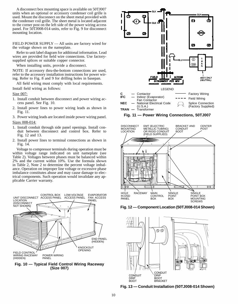
Adisconnect box mounting space is available on 50TJ007units when an optional or accessory condenser coil grille isused. Mount the disconnect on the sheet metal provided withthe condenser coil grille. The sheet metal is located adjacentto the corner post on the left side of the power wiring accesspanel. For 50TJ008-014 units, refer to Fig. 9 for disconnectmounting location.
FIELD POWER SUPPLY—All units are factory wired forthe voltage shown on the nameplate.Refer to unit label diagram for additional information. Lead
wires are provided for field wire connections. Use factory-supplied splices or suitable copper connector.When installing units, provide a disconnect.
NOTE: If accessory thru-the-bottom connections are used,refer to the accessory installation instructions for power wir-ing. Refer to Fig. 8 and 9 for drilling holes in basepan.All field wiring must comply with local requirements.
Install field wiring as follows:Size 007:1. Install conduit between disconnect and power wiring ac-
cess panel. See Fig. 10.2. Install power lines to power wiring leads as shown in
Fig. 11.3. Power wiring leads are located inside power wiring panel.Sizes 008-014:1. Install conduit through side panel openings. Install con-
duit between disconnect and control box. Refer toFig. 12 and 13.
2. Install power lines to terminal connections as shown inFig. 14.Voltage to compressor terminals during operation must be
within voltage range indicated on unit nameplate (seeTable 2). Voltages between phases must be balanced within2% and the current within 10%. Use the formula shownin Table 2, Note 2 to determine the percent voltage imbal-ance. Operation on improper line voltage or excessive phaseimbalance constitutes abuse and may cause damage to elec-trical components. Such operation would invalidate any ap-plicable Carrier warranty.
LOW-VOLTAGEACCESS PANEL
FIELD CONTROLWIRING RACEWAY(HIDDEN)
POWER WIRINGPANEL
KNOCKOUTOPENING
END PANEL(HIDDEN)
EVAPORATORFAN ACCESSPANEL
UNIT DISCONNECTLOCATION(DISCONNECTNOT SHOWN)
CONTROL BOXACCESS PANEL
Fig. 10 — Typical Field Control Wiring Raceway(Size 007)
LEGEND
C — Contactor Factory WiringIFC — Indoor (Evaporator) Field WiringFan ContactorNEC — National Electrical Code Splice Connection
(U.S.A.) (Factory Supplied)TRAN — Transformer
Fig. 11 — Power Wiring Connections, 50TJ007
HOLE IN END PANEL
RACEWAY MAINCONTROL BOX
SINGLE POINTBOX
SINGLE POINT BOXMOUNTING SCREWS
DISCONNECTMOUNTINGLOCATION
EMT (ELECTRICMETALLIC TUBING)OR RIGID CONDUIT(FIELD SUPPLIED)
BRACKET ANDCONDUITBOOT
CENTERPOST
Fig. 12—Component Location (50TJ008-014 Shown)
Fig. 13—Conduit Installation (50TJ008-014 Shown)
10

FIELD CONTROL WIRING — Install a Carrier-approvedaccessory thermostat assembly according to installation in-structions included with the accessory. Locate thermostat as-sembly on a solid wall in the conditioned space to sense av-erage temperature in accordance with thermostat installationinstructions.
Route thermostat cable or equivalent single leads of col-ored wire subbase terminals to low-voltage connections onunit (shown in Fig. 15 and 16) as described below.
NOTE: For wire runs up to 15 m (50 ft), use no. 18 AWG(American Wire Gage) insulated wire (35 C minimum). For15 m to 23 m (50 to 75 ft), use no. 16 AWG insulated wire(35 C minimum). For over 23 m (75 ft), use no. 14 AWGinsulated wire (35 C minimum). All wire larger than no. 18AWG cannot be directly connected to the thermostat and willrequire a junction box and a splice at the thermostat. SeeTable 3 for American/European wire conversions.50TJ007 Units:1. Feed control wires through the raceway located between
the condenser coil top cover and burner side panel. SeeFig. 10.
2. Connect control wires to corresponding screw terminals(the low-voltage connections located inside low-voltageaccess panel). The low-voltage connections provide theUL (Underwriters’ Laboratories, U.S.A.) required clear-ance between high- and low-voltage wiring.
50TJ008-014 Units:1. If unit is mounted on roof curb and accessory thru-the-
curb service plate connection is used, route wire throughconnection plate.
2. Pass control wires through the hole provided on unit (seeconnection D, Connection Sizes table, Fig. 9).
3. Feed wire through the raceway built into the corner postto the 24-v barrier located on the left side of the con-trol box. See Fig. 12. The raceway provides theUL-required (Underwriters’ Laboratories, U.S.A.) clear-ance between the high- and low-voltage wiring.
4. Connect thermostat wires to screw terminals of low-voltage connector.
LEGEND
C — ContactorIFC — Indoor (Evaporator) Fan ContactorNEC — National Electrical Code (U.S.A.)TB — Terminal Block
Field WiringFactory Wiring
Splice Connection (Factory Supplied)
Fig. 14 — Power Wiring Connections, 50TJ008-014
LEGENDC — ContactorCAP — CapacitorGND — GroundIFC — Indoor (Evaporator) Fan Contactor
IFR — Indoor (Evaporator) Fan RelayNEC — National Electrical Code (U.S.A.)TB — Terminal BlockTRAN — Transformer
Fig. 15 — Field Control Wiring Connections, 50TJ007
11

Table 2 — Electrical Data
UNIT50TJ
NOMINALVOLTAGE(50 Hz)
VOLTAGERANGE COMPR OFM
(each) IFM ELECTRIC HEAT* POWER SUPPLYMINIMUMUNIT
DISCONNECT
Min Max RLA LRA FLA FLA NominalkW† FLA MCA MOCP** FLA LRA
007 400(3 phase) 360 440 10.6 73.0 1.6 2.6
— — 17.5 25 17
95
6.0 7.2 17.5 25 1711.5 13.8 17.6 25 1714.0 16.8 20.8 25 1923.0 27.8 32.0 35 2925.5 30.7 35.2 40 32
008
220/240(3 phase) 187 254 13.6 73.4 1.4 5.8
—/— —/— 39.2/ 39.2 45/ 45 41/ 41
194/194
8.7/10.4 22.9/ 25.0 39.2/ 39.2 45/ 45 41/ 4113.4/16.0 35.3/ 38.5 51.3/ 55.4 60/ 60 47/ 5120.8/24.8 54.7/ 59.7 75.6/ 81.8 80/ 90†† 70/ 7526.9/32.0 70.5/ 77.0 95.4/103.5 100/110†† 88/ 9535.6/42.4 93.5/102.0 124.1/134.8 125/150†† 114/124
400(3 phase) 360 440 6.2 37.7 0.8 2.6
— — 18.0 25 19
99
9.7 15.2 22.2 25 2111.5 18.0 25.8 30 2419.3 30.3 41.1 45 3822.9 36.1 48.4 50 4529.0 45.5 60.1 70†† 55
009
220/240(3 phase) 187 254 15.8 92.0 1.4 5.8
—/— —/— 44.2/ 44.2 50/ 50 46/ 46
231/231
8.7/10.4 22.9/ 25.0 44.2/ 44.2 50/ 50 46/ 4613.4/16.0 35.3/ 38.5 51.3/ 55.4 50/ 60 47/ 5120.8/24.8 54.7/ 59.7 75.6/ 81.8 80/ 90†† 70/ 7526.9/32.0 70.5/ 77.0 95.4/103.5 100/110†† 88/ 9535.6/42.4 93.5/102.0 124.1/134.8 125/150†† 114/124
400(3 phase) 360 440 7.4 46.0 0.8 2.6
— — 20.7 25 22
116
9.7 15.2 23.2 30 2411.5 18.0 25.8 30 2419.3 30.3 41.1 45 3822.9 36.1 48.4 50 4529.0 45.5 60.1 70†† 54
012
220/240(3 phase) 187 254 17.9 110.0 1.4 7.5
—/— —/— 48.9/ 48.9 60/ 60 51/ 51
267/2678.7/10.4 22.9/ 25.0 48.9/ 48.9 60/ 60 51/ 5113.4/16.0 35.3/ 38.5 53.5/ 57.5 60/ 60 52/ 5326.9/32.0 70.5/ 77.0 97.6/105.6 100/110†† 90/ 9742.0/50.0 110.2/120.3 147.2/129.7 150/150†† 135/147
400(3 phase) 360 440 8.6 55.0 0.8 3.4
— — 23.4 30 24
134
9.7 18.0 23.4 30 2419.3 30.3 42.1 45 3922.9 36.1 49.4 50 4529.0 45.5 61.1 70†† 5634.7 54.6 72.5 80†† 67
014 400(3 phase) 360 440 10.4 73.0 0.8 6.2
— — 29.4 35 31
190
11.5 18.0 29.4 35 3119.3 30.3 40.8 45 3822.9 36.1 47.3 50 4429.0 45.5 58.2 60 5434.7 54.6 68.6 70†† 63
LEGENDCOMPR — CompressorFLA — Full Load AmpsHACR — Heating, Air Conditioning and
RefrigerationIFM — Indoor (Evaporator) Fan MotorLRA — Locked Rotor AmpsMCA — Minimum Circuit AmpsMOCP — Maximum Overcurrent ProtectionNEC — National Electrical CodeOFM — Outdoor (Condenser) Fan MotorRLA — Rated Load Amps*Heater capacity (kW) is based on heater voltage of 220 v, 240 v and 400 v.†If power distribution voltage to unit varies from rated heater voltage, heaterkW will vary accordingly. Heaters are field installed only.
**Fuse or HACR circuit breaker.††Fusing in single point box provides the required branch circuit protection.
NOTES:1. In compliance with NEC requirements (U.S.A. Standard) for multi-
motor and combination load equipment (refer to NECArticles 430 and 440),the overcurrent protective device for the unit shall be fuse or HACR breaker.
2. Unbalanced 3-Phase Supply VoltageNever operate a motor where a phase imbalance in supply voltage is greaterthan 2%. Use the following formula to determine the percent of voltageimbalance.% Voltage imbalance
max voltage deviation from average voltage= 100 xaverage voltage
Example: Supply voltage is 400-3-50.AB =393 vBC =403 vAC =396 v
393 + 403 + 396Average Voltage =3
1192=3
= 397Determine maximum deviation from average voltage:(AB) 397 – 393 = 4 v(BC) 403 – 397 = 6 v(AC) 397 – 396 = 1 v
Maximum deviation is 6 v.Determine percent voltage imbalance.
6% Voltage imbalance = 100 x397
= 1.5%This amount of phase imbalance is satisfactory as it is below the maximumallowable 2%.
IMPORTANT: If the supply voltage phase imbalance is more than2%, contact your local electric utility company immediately.
12

Table 3 — American/European Wire Conversions
AMERICAN EUROPEANIndustryStandardSize
AmericanConversion
(mm2)
IndustryStandardSize (mm2)
18 AWG 0.82 1.016 AWG 1.30 1.514 AWG 2.08 2.512 AWG 3.30 4.010 AWG 5.25 6.08 AWG 6.36 10.06 AWG 13.29 16.04 AWG 21.14 25.03 AWG 26.65 —2 AWG 33.61 35.01 AWG 42.39 50.0
1/0 AWG 53.49 —2/0 AWG 67.42 70.03/0 AWG 85.00 95.04/0 AWG 107.19 120.0250 kcmil 126.64 150.0300 kcmil 151.97 —350 kcmil 177.90 185.0400 kcmil 202.63 240.0500 kcmil 253.29 300.0600 kcmil 303.95 —
LEGEND
AWG — American Wire Gagekcmil — Thousand Circular Mils
HEATANTICIPATORSETTINGFORACCESSORYELEC-TRIC HEATERS— Set heat anticipator setting as shown inTable 4.
Step 6 — Adjust Factory-Installed OptionsAPOLLOCONTROL—The optionalApollo control is usedto actively monitor all modes of operation as well as indoor(evaporator) fan status, filter status, and indoor-air quality.The Apollo control is designed to work with Carrier TEMPand VVTt systems.The thermostat must be wired to theApollo control before
starting the unit. Refer to the Apollo control installation in-structions for information on installing the thermostat. SeeFig. 17 for Apollo control location.
MANUAL OUTDOOR-AIR DAMPER
1. Determine quantity of ventilation air required for build-ing. Record amount for use in Step 9.
2. Remove filter access panel by raising panel and swing-ing panel outward. Panel is now disengaged from trackand can be removed. No tools are required to removefilter access panel. Remove and save outdoor-air open-ing panel and screws. See Fig. 18.
Table 4 — Heat Anticipator Settings
UNIT50TJ
220 v
HeaterkW
ConfigurationPart No.
CRHEATER1 Stage 2 StageStage 1 Stage 1 Stage 2
008,009,012
8.7 .3 NA NA 117A0013.4 .3 NA NA 110A0020.8 .6 .3 .3 111A0026.9 .6 .3 .3 112A0035.6 .9 .6 .3 117A00, 112A0042.0 .9 .6 .3 110A00, 112A00
UNIT50TJ
400 v
HeaterkW
ConfigurationPart No.
CRHEATER1 Stage 2 StageStage 1 Stage 1 Stage 2
007
6.0 1.1 .8 .3 106A0011.5 1.1 .8 .3 108A0014.0 1.1 .8 .3 109A0023.0 1.1 .8 .3 108A00, 108A0025.5 1.1 .8 .3 108A00, 109A00
008-014
9.7* .3 NA NA 116A0011.5 .3 NA NA 113A0019.3 .3 NA NA 114A0022.9 .3 NA NA 115A0029.0 .6 .3 .3 116A00, 114A0034.7 .6 .3 .3 113A00, 115A00
*Not available for 014 units.
LEGENDC — ContactorCB — Circuit BreakerCONN — ConnectionGND — Ground
IFC — Indoor (Evaporator) Fan ContactorIFR — Indoor (Evaporator) Fan RelayNEC — National Electrical Code (U.S.A.)TRAN — Transformer
Fig. 16 — Field Control Wiring Connections, 50TJ008-014
13

3. Separate hood and screen from basepan by removing thescrews and brackets securing them. Save all screws anddiscard brackets.
4. Replace outdoor-air opening panel.5. Place hood on front of outdoor-air opening panel. See
Fig. 19 for hood details.6. Secure top of hood with the screws removed in Step 3.
See Fig. 20.7. Remove and save screws fromsides of themanual outdoor-
air damper.8. Align screw holes on hood with screw holes on side of
manual outdoor-air damper. See Fig. 19 and 20. Securehood with screws saved from Step 7.
9. Adjust minimum position setting of the damper bladeby adjusting the manual outdoor-air adjustment screwson the front of the damper blade. See Fig. 18. Slide bladevertically until it is in the appropriate position deter-mined by Fig. 21 or 22. Tighten screws.
10. Remove and save screws currently on sides of hood.11. Insert screen and secure to the hood using the screws
saved in Step 10. See Fig. 20.
OPTIONAL DURABLADE ECONOMIZER — The op-tional economizer hood assembly is packaged and shippedin the filter section. Damper blades and control boards areinstalled at the factory and the economizer is shipped in thevertical discharge position.NOTE: Horizontal discharge block-off plate is shipped withthe air hood package. If unit is to be used for vertical dis-charge application, discard this plate.Assembly
1. Determine if ventilation air is required in building. Ifso, determine the minimum amount to be supplied byeach unit and record quantity of ventilation air neededfor use in Step 8.
2. Remove filter access panel by raising panel and swing-ing panel outward. Panel is now disengaged from trackand can be removed. No tools are required to removefilter access panel. Remove outdoor-air opening panel.Save panels and screws. See Fig. 23. Remove optionaloutdoor-air damper hood package from filter section.
CONTROLWIRING
APOLLOCONTROL
WIRING TOTHERMOSTAT
Fig. 17 — Apollo Control Factory-Installedin Typical Unit
OUTDOORAIR OPENINGPANEL
SCREWS(SIDE)
MANUAL OUTDOOR-AIRADJUSTMENT SCREWS
DAMPERBLADE
Fig. 18 — Damper Panel with Manual Outdoor-AirDamper Installed
Fig. 19 — Outdoor-Air Hood Details
HOODSCREENLOCATION(SCREENNOTSHOWN)
HOOD
SCREWHOLES(TOP)
Fig. 20 — Damper with Hood Attached
14

3. Assemble outdoor-air hood top and side plates as shownin Fig. 24. Install seal strips on hood top and sides. Putaside screen retainer and retainer screw for later assem-bly. Do not attach hood to unit at this time.
4. On 012 and 014 units, install vertical discharge block-off plate over duct openings. See Fig. 25.NOTE: Be sure to engage rear economizer flange undertabs in vertical return-air opening.
Fig. 21 — Position Setting (50TJ007 Units)
Fig. 22 — Position Setting (50TJ008-014 Units)
OUTDOOR-AIROPENINGPANEL
BLOCK-OFFPANEL
FILTERACCESSDOOR
Fig. 23 — Typical Access Panel Location
Fig. 24 — Outdoor-Air Hood Details
Fig. 25 — Block-Off Plate Location(50TJ012,014 only)
15

5. To convert to horizontal discharge application:a. Rotate the economizer 90 degrees until the
economizer motor faces the condenser section (seeFig. 26).
b. Rotate the barometric relief damper hinge 90 de-grees. Barometric relief damper should open verti-cally to operate properly.
c. Install horizontal discharge block-off plate over theopening on the access panel. (Block-off plate MUSTbe installed before installing hood assembly.) SeeFig. 27.
6. Insert economizer plug into economizer harness. Re-move tape from barometric relief damper. See Fig. 28.
7. If ventilation air is not required, proceed to Step 9. Ifventilation air is required, determine the minimum po-sition setting for required airflow. See Fig. 29 or 30. Ad-just minimum position setting by adjusting the screwson the position setting bracket. See Fig. 31. Slide bracketuntil the top screw is in the position determined byFig. 29 or 30. Tighten screws.
8. Remove tape from outdoor-air thermostat (OAT). Fas-ten OAT to inside of hood using screws and speed clipsprovided. See Fig. 32. Make sure OAT terminals are po-sitioned up.
9. Replace outdoor-air opening panel using screws fromStep 2. Replace filter access panel. Ensure the filter ac-cess panel slides along the tracks and is securelyengaged.
10. Fasten hood top and side plate assembly to outdoor-airopening panel with screws provided.
11. Place knob supplied with economizer on OAT. SeeFig. 32. Set for 3° F below indoor room thermostatset-ting. If accessory enthalpy control (EC) is used in placeof OAT, see instructions shipped with EC for installa-tion and adjustment. See Fig. 32.
12. Connect OAT per Fig. 33.13. Slide outdoor-air inlet screen into screen track on hood
side plate. While holding screen in place, fasten screenretainer to hood using screws provided.
NOTE: Refer to Fig. 34 for Durablade economizer baromet-ric relief damper characteristics.
ECONOMIZERCONTROLBOARD
BAROMETRICRELIEFDAMPER
ECONOMIZERPLUG
ECONOMIZERMOTOR
Fig. 26 — Horizontal Durablade EconomizerInstallation
(90 Degrees Rotation)
BLOCK-OFF PLATE
Fig. 27 — Horizontal Discharge Block-Off Plate
ECONOMIZERCONTROLBOARD
ECONOMIZERPLUG
ECONOMIZERMOTOR
TOPSCREW
BAROMETRICRELIEF DAMPER
POSITION SETTINGBRACKET
Fig. 28 — Durablade Economizer Installedin Unit
16

Example:Given —Return-Air Negative Static Pressure . . . . . . . . . . . . . 50 Pa (0.2 in. wg)Outdoor Airflow . . . . . . . . . . . . . . . . . . . . . . . . . 425 L/s (900 cfm)
Determine —Setting = 125 mm (5 in.)
Fig. 29 — Durablade Economizer DamperMinimum Position Setting, 50TJ007
Example:Given —Negative Pressure . . . . . . . . . . . . . . . . . . . . . . . . . . . . . 25 Pa (0.1 in. wg)Outdoor Airflow . . . . . . . . . . . . . . . . . . . . . . . . . . . . . . 520 L/s (1100 cfm)
Determine —Setting = 150 mm (6 in.)
Fig. 30 — Durablade Economizer Damper MinimumPosition Setting, 50TJ008-014
17

Fig. 31 — Position Setting Bracket
MIN
IMU
MP
OS
ITION
OP
EN
3 1
TPP
1
T1
4 2 5
S SO
D
C
TR
B
RE
V. B
19
88
18
A
%HUM ID ITY 9070603010 D
CB
A60
65
70
75
55
50
85
80
DA
MP
ER
DA
MP
ER
CLO
SE
D
OP
EN
OU
TD
OO
R T
EM
P.°F
REV.97-3672
CW
–S
ET
PO
INT
S–
CC
W
CO
NTA
CT
S S
HO
WN
IN H
IGH
EN
TH
AL
PY
RU
SH
AT
24
VA
C3
mA
MIN
. AT
11 V
DC
CO
NTA
CT
RA
TIN
GS
: 1.5
A R
UN
, 3.5
A IN
OR
UN
PO
WE
RE
D S
TAT
E
12
3
TR
TR
12
4VA
C
EN
TH
AL
PY
CO
NT
RO
L
Fig. 32 — Outdoor-Air Thermostat/Enthalpy Control Installation
18

Step 7 — Adjust Evaporator-Fan Speed —Adjust evaporator-fan speed to meet jobsite conditions.For units with electric heating, requiredminimum L/s (cfm)
is 850 (1800) for 50TJ007, 1062 (2250) for 50TJ008; 1062(2250) for 50TJ009; and 1416 (3000) for 50TJ012 and 014with the following exceptions:
UNIT50TJ
UNITVOLTAGE
HEATERkW
UNITCONFIGUR-
ATION
REQUIREDMINIMUML/s Cfm
012 220 42.0 Horizontal 1510 3200
012, 014 400 34.7 Horizontal orVertical 1510 3200
Tables 5 and 6 show fan r/s and rpm at motor pulley set-tings for standard motors. See Table 7 for evaporator-fan mo-tor performance. Refer to Tables 8-23 to determine fan speedsettings. Fan motor pulleys are factory set for speed shownin Tables 1A and 1B. Check pulley alignment and belt ten-sion prior to start-up.To change fan speed:1. Shut off unit power supply.2. Loosen belt by loosening fan motor mounting nuts. See
Fig. 35 and 36.3. Loosen movable pulley flange setscrew (see Fig. 37).
4. Screwmovable flange toward fixed flange to increase speedand away from fixed flange to decrease speed. Increasingfan speed increases load on motor. Do not exceed maxi-mum speed specified in Tables 1A and 1B.
5. Set movable flange at nearest keyway of pulley hub andtighten setscrew. (See Tables 1Aand 1B for speed changefor each full turn of pulley flange.)
To align fan and motor pulleys:1. Loosen fan pulley setscrews.2. Slide fan pulley along fan shaft.3. Make angular alignment by looseningmotor frommounting.To adjust belt tension:1. Loosen fan motor mounting nuts.2. Sizes 007-009— Slide motor mounting plate away from
fan scroll for proper belt tension (13 mm [1⁄2-in.] deflec-tion with one finger) and tighten mounting nuts. SeeFig. 35.
Sizes 012,014— Slide motor mounting plate downwardto tighten belt tension. See Fig. 36.
3. Adjust bolt and nut on mounting plate to secure motor infixed position.
Fig. 33 — Wiring Connections forOutdoor-Air Thermostat (OAT)
Fig. 34 — Durablade Economizer Barometric ReliefDamper Characteristics
MOTOR MOUNTINGNUTS AND BOLTS
Fig. 35 — Belt Drive Motor Mounting,50TJ007-009
Fig. 36 — Belt Drive Motor Mounting,50TJ012,014
19

Table 5 — Fan R/s at Motor Pulley Settings (SI)
UNIT50TJ
MOTOR PULLEY TURNS OPEN0 1⁄2 1 11⁄2 2 21⁄2 3 31⁄2 4 41⁄2 5
007 20.08 19.67 19.17 18.75 18.25 17.83 17.33 16.92 16.42 16.00 15.50008,009 14.67 14.25 13.83 13.33 12.92 12.50 12.08 11.67 11.25 10.83 10.33
012 15.00 14.58 14.25 13.92 13.58 13.25 12.92 12.58 12.25 11.92 11.50014 14.83 14.58 14.25 13.72 13.67 13.33 13.08 12.75 12.50 12.17 11.83
Table 6 — Fan Rpm at Motor Pulley Settings (English)
UNIT50TJ
MOTOR PULLEY TURNS OPEN0 1⁄2 1 11⁄2 2 21⁄2 3 31⁄2 4 41⁄2 5
007 1205 1180 1150 1125 1095 1070 1040 1015 985 960 930008,009 880 855 830 800 775 750 725 700 675 650 620
012 900 875 855 835 815 795 775 755 735 715 690014 890 875 855 835 820 800 785 765 750 730 710
Table 7 — Evaporator-Fan Motor Performance
UNIT50TJ
EVAPORATOR-FANMOTOR
UNIT RATEDVOLTAGE
MAXIMUMACCEPTABLECONTINUOUS
BkW*
MAXIMUMACCEPTABLECONTINUOUS
BHP*
MAXIMUMACCEPTABLEOPERATING
WATTS
MAXIMUMAMP DRAW
007 Standard 400 1.79 2.40 2120 2.7
008 Standard220
1.79 2.40 21206.1
400 2.7
009 Standard220
1.79 2.40 21206.1
400 2.7
012 Standard220
2.16 2.90 21206.1
400 2.7
014 Standard220
3.13 4.20 377512.6
400 5.7
LEGEND
Bhp — Brake HorsepowerBkW — kW x Motor Efficiency
*Extensive motor and electrical testing on these units ensures thatthe full horsepower and kilowatt range of the motors can be utilizedwith confidence. Using your fan motors up to the horsepower andkilowatt ratings shown in this table will not result in nuisance trippingor premature motor failure. Unit warranty will not be affected.
Fig. 37 — Evaporator-Fan Pulley Adjustment
20
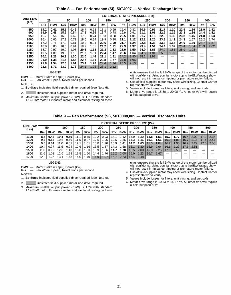
Table 8 — Fan Performance (SI), 50TJ007 — Vertical Discharge Units
AIRFLOW(L/s)
EXTERNAL STATIC PRESSURE (Pa)
25 50 100 150 200 250 300 350 400
R/s BkW R/s BkW R/s BkW R/s BkW R/s BkW R/s BkW R/s BkW R/s BkW R/s BkW
850 14.2 0.41 15.1 0.46 16.7 0.58 18.1 0.69 19.4 0.82 20.6 0.96 21.7 1.10 22.9 1.26 23.9 1.42900 14.9 0.48 15.8 0.54 17.3 0.66 18.7 0.78 19.9 0.91 21.1 1.05 22.2 1.19 23.3 1.36 24.4 1.52950 15.7 0.56 16.5 0.62 17.9 0.74 19.3 0.88 20.5 1.01 21.7 1.15 22.8 1.30 23.8 1.46 24.8 1.631000 16.4 0.65 17.2 0.71 18.6 0.84 19.9 0.98 21.1 1.12 22.2 1.26 23.3 1.42 24.3 1.57 25.2 1.741050 17.2 0.75 17.9 0.81 19.2 0.94 20.6 1.09 21.7 1.24 22.8 1.38 23.8 1.54 24.9 1.70 25.7 1.871100 18.0 0.85 18.6 0.91 19.9 1.05 21.2 1.21 22.3 1.37 23.4 1.51 24.4 1.67 25.4 1.84 26.3 2.021150 18.7 0.97 19.2 1.03 20.6 1.18 21.8 1.33 23.0 1.50 24.0 1.66 24.9 1.81 25.9 1.98 — —1200 19.5 1.09 19.9 1.16 21.3 1.31 22.4 1.47 23.6 1.64 24.6 1.81 25.5 1.97 — — — —1250 20.2 1.23 20.8 1.30 22.0 1.46 23.1 1.61 24.2 1.80 25.2 1.97 — — — — — —1300 21.0 1.38 21.5 1.45 22.7 1.61 23.8 1.77 24.8 1.96 — — — — — — — —1350 21.8 1.54 22.3 1.61 23.4 1.78 24.4 1.94 25.5 2.13 — — — — — — — —1400 22.6 1.71 23.0 1.78 24.1 1.95 25.1 2.12 — — — — — — — — — —
LEGEND
BkW — Motor Brake (Output) Power (kW)R/s — Fan Wheel Speed, Revolutions per secondNOTES:1. Boldface indicates field-supplied drive required (see Note 6).
2. indicates field-supplied motor and drive required.3. Maximum usable output power (BkW) is 1.79 with standard
1.12-BkW motor. Extensive motor and electrical testing on these
units ensures that the full BkW range of the motor can be utilizedwith confidence. Using your fanmotors up to the BkW ratings shownwill not result in nuisance tripping or premature motor failure.
4. Use of field-supplied motor may affect wire sizing. Contact Carrierrepresentative to verify.
5. Values include losses for filters, unit casing, and wet coils.6. Motor drive range is 15.50 to 20.08 r/s. All other r/s’s will require
a field-supplied drive.
Table 9 — Fan Performance (SI), 50TJ008,009 — Vertical Discharge Units
AIRFLOW(L/s)
EXTERNAL STATIC PRESSURE (Pa)
50 100 150 200 250 300 350 400 450 500
R/s BkW R/s BkW R/s BkW R/s BkW R/s BkW R/s BkW R/s BkW R/s BkW R/s BkW R/s BkW
1100 8.7 0.42 10.1 0.59 11.1 0.75 12.2 0.93 13.1 1.12 14.0 1.30 14.8 1.51 15.7 1.77 16.4 2.02 17.2 2.351200 9.3 0.52 10.5 0.69 11.6 0.87 12.6 1.05 13.5 1.26 14.3 1.46 15.1 1.66 15.9 1.88 16.7 2.14 17.4 2.441300 9.8 0.64 11.0 0.81 12.1 1.01 13.0 1.20 13.9 1.41 14.7 1.63 15.5 1.84 16.2 1.98 16.9 2.29 17.6 2.561400 10.4 0.77 11.5 0.94 12.6 1.16 13.5 1.37 14.3 1.58 15.1 1.80 15.9 2.04 16.6 2.27 17.3 2.51 — —1500 11.0 0.92 12.0 1.10 13.0 1.33 13.9 1.56 14.7 1.78 15.5 2.00 16.3 2.25 17.0 2.50 — — — —1600 11.6 1.08 12.6 1.28 13.5 1.50 14.4 1.76 15.2 2.00 16.0 2.23 16.7 2.47 — — — — — —1700 12.2 1.26 13.1 1.48 14.0 1.70 14.9 1.97 15.7 2.23 16.4 2.48 — — — — — — — —
LEGEND
BkW — Motor Brake (Output) Power (kW)R/s — Fan Wheel Speed, Revolutions per secondNOTES:1. Boldface indicates field-supplied drive required (see Note 6).
2. indicates field-supplied motor and drive required.3. Maximum usable output power (BkW) is 1.79 with standard
1.12-BkW motor. Extensive motor and electrical testing on these
units ensures that the full BkW range of the motor can be utilizedwith confidence. Using your fanmotors up to the BkW ratings shownwill not result in nuisance tripping or premature motor failure.
4. Use of field-supplied motor may affect wire sizing. Contact Carrierrepresentative to verify.
5. Values include losses for filters, unit casing, and wet coils.6. Motor drive range is 10.33 to 14.67 r/s. All other r/s’s will require
a field-supplied drive.
21

Table 10 — Fan Performance (SI), 50TJ012 — Vertical Discharge Units
AIRFLOW(L/s)
EXTERNAL STATIC PRESSURE (Pa)
50 100 150 200 250 300 350 400 450 500
R/s BkW R/s BkW R/s BkW R/s BkW R/s BkW R/s BkW R/s BkW R/s BkW R/s BkW R/s BkW
1300 8.4 0.37 9.6 0.51 10.8 0.61 11.7 0.69 12.6 0.81 13.3 0.90 14.3 1.05 15.1 1.27 15.9 1.48 16.7 1.671400 8.8 0.46 10.0 0.59 11.1 0.71 12.0 0.82 12.9 0.93 13.7 1.04 14.5 1.17 15.4 1.35 16.2 1.56 16.8 1.751500 9.2 0.55 10.4 0.68 11.5 0.81 12.4 0.94 13.2 1.06 14.0 1.19 14.8 1.26 15.6 1.44 16.4 1.62 17.1 1.831600 9.7 0.65 10.8 0.79 11.8 0.93 12.8 1.07 13.6 1.19 14.4 1.33 15.1 1.46 15.8 1.59 16.5 1.72 17.3 1.911700 10.2 0.75 11.2 0.91 12.2 1.06 13.1 1.20 13.9 1.34 14.7 1.48 15.4 1.63 16.1 1.76 16.7 1.89 17.4 2.041800 10.6 0.87 11.7 1.05 12.6 1.20 13.5 1.35 14.3 1.51 15.0 1.65 15.7 1.80 16.4 1.95 17.1 2.10 17.7 2.241900 11.1 1.01 12.1 1.19 13.0 1.35 13.9 1.52 14.7 1.68 15.4 1.84 16.1 1.99 16.8 2.14 17.4 2.31 18.0 2.462000 11.6 1.16 12.5 1.35 13.4 1.52 14.3 1.69 15.0 1.86 15.8 2.04 16.5 2.21 17.1 2.36 17.7 2.53 — —2100 12.0 1.32 13.0 1.53 13.8 1.70 14.6 1.88 15.4 2.07 16.1 2.25 16.8 2.43 — — — — — —2200 12.5 1.50 13.4 1.71 14.3 1.91 15.1 2.09 15.8 2.29 16.5 2.48 — — — — — — — —2300 13.0 1.70 13.9 1.91 14.7 2.13 15.5 2.31 16.2 2.52 — — — — — — — — — —
LEGEND
BkW — Motor Brake (Output) Power (kW)R/s — Fan Wheel Speed, Revolutions per secondNOTES:1. Boldface indicates field-supplied drive required (see Note 6).
2. indicates field-supplied motor and drive required.3. Maximum usable output power (BkW) is 2.16 with standard
1.50-BkW motor. Extensive motor and electrical testing on these
units ensures that the full BkW range of the motor can be utilizedwith confidence. Using your fanmotors up to the BkW ratings shownwill not result in nuisance tripping or premature motor failure.
4. Use of field-supplied motor may affect wire sizing. Contact Carrierrepresentative to verify.
5. Values include losses for filters, unit casing, and wet coils.6. Motor drive range is 11.50 to 15.00 r/s. All other r/s’s will require
a field-supplied drive.
Table 11 — Fan Performance (SI), 50TJ014 — Vertical Discharge Units
AIRFLOW(L/s)
EXTERNAL STATIC PRESSURE (Pa)
50 100 150 200 250 300 350 400 450 500
R/s BkW R/s BkW R/s BkW R/s BkW R/s BkW R/s BkW R/s BkW R/s BkW R/s BkW R/s BkW
1750 10.9 0.84 11.9 0.98 12.8 1.12 13.6 1.25 14.4 1.38 15.1 1.55 15.8 1.69 16.5 1.84 17.2 1.98 17.7 2.101800 11.1 0.89 12.1 1.04 13.0 1.19 13.8 1.32 14.6 1.45 15.3 1.63 16.0 1.77 16.7 1.92 17.3 2.07 17.9 2.211850 11.4 0.95 12.4 1.11 13.2 1.27 14.0 1.40 14.7 1.53 15.5 1.70 16.2 1.86 16.8 2.01 17.5 2.17 18.1 2.321900 11.6 1.02 12.6 1.19 13.4 1.34 14.2 1.48 14.9 1.61 15.6 1.77 16.3 1.95 17.0 2.11 17.7 2.27 18.3 2.421950 11.9 1.09 12.8 1.26 13.7 1.42 14.4 1.57 15.1 1.70 15.8 1.86 16.5 2.04 17.2 2.21 17.8 2.37 18.4 2.532000 12.1 1.16 13.0 1.34 13.9 1.50 14.6 1.66 15.3 1.80 16.0 1.94 16.7 2.13 17.3 2.31 18.0 2.47 18.6 2.642050 12.4 1.24 13.2 1.42 14.1 1.58 14.8 1.75 15.5 1.89 16.2 2.03 16.9 2.21 17.5 2.41 18.1 2.58 18.7 2.752100 12.6 1.32 13.5 1.51 14.3 1.67 15.0 1.85 15.7 2.00 16.4 2.13 17.0 2.31 17.7 2.51 18.3 2.69 18.9 2.862150 12.8 1.41 13.7 1.60 14.5 1.77 15.3 1.95 15.9 2.10 16.6 2.24 17.2 2.41 17.8 2.62 18.5 2.80 19.1 2.982200 13.1 1.49 13.9 1.69 14.7 1.86 15.5 2.05 16.1 2.21 16.8 2.36 17.4 2.51 18.0 2.71 18.6 2.92 19.2 3.112250 13.3 1.59 14.2 1.79 15.0 1.96 15.7 2.15 16.4 2.32 17.0 2.48 17.6 2.62 18.2 2.82 18.8 3.03 19.4 3.232300 13.6 1.68 14.4 1.89 15.2 2.07 15.9 2.25 16.6 2.44 17.2 2.60 17.8 2.75 18.4 2.93 19.0 3.15 19.5 3.362350 13.8 1.78 14.6 1.99 15.4 2.18 16.1 2.36 16.8 2.56 17.4 2.72 18.0 2.89 18.6 3.05 19.2 3.26 19.7 3.492400 14.1 1.88 14.9 2.10 15.6 2.30 16.3 2.48 17.0 2.68 17.6 2.85 18.2 3.02 18.8 3.17 19.3 3.38 19.9 3.622450 14.3 1.99 15.1 2.20 15.8 2.42 16.6 2.60 17.2 2.80 17.8 2.98 18.4 3.15 19.0 3.32 19.5 3.50 20.1 3.742500 14.6 2.10 15.3 2.31 16.1 2.54 16.8 2.72 17.4 2.93 18.0 3.12 18.6 3.30 19.2 3.47 19.7 3.64 20.3 3.862550 14.8 2.21 15.6 2.43 16.3 2.66 17.0 2.85 17.6 3.06 18.2 3.27 18.8 3.45 19.4 3.62 19.9 3.78 20.4 4.002600 15.1 2.33 15.8 2.56 16.5 2.80 17.2 2.98 17.9 3.20 18.4 3.41 19.0 3.59 19.6 3.77 20.1 3.94 20.6 4.142650 15.3 2.46 16.1 2.68 16.7 2.92 17.4 3.12 18.1 3.33 18.7 3.56 19.2 3.75 19.8 3.93 20.3 4.11 20.8 4.292700 15.6 2.59 16.3 2.81 17.0 3.06 17.6 3.27 18.3 3.47 18.9 3.71 19.4 3.91 20.0 4.09 20.5 4.28 — —2750 15.8 2.72 16.5 2.95 17.2 3.21 17.9 3.42 18.5 3.62 19.1 3.86 19.6 4.07 20.2 4.27 — — — —2800 16.1 2.86 16.8 3.09 17.4 3.36 18.1 3.57 18.7 3.78 19.3 4.02 19.9 4.24 — — — — — —2850 16.3 2.98 17.0 3.24 17.7 3.50 18.3 3.74 18.9 3.94 19.5 4.18 — — — — — — — —2900 16.6 3.15 17.3 3.39 17.9 3.65 18.5 3.90 19.2 4.10 — — — — — — — — — —2950 16.8 3.30 17.5 3.54 18.2 3.80 18.8 4.06 19.4 4.27 — — — — — — — — — —3000 17.1 3.45 17.8 3.70 18.4 3.97 19.0 4.24 — — — — — — — — — — — —3050 17.3 3.62 18.0 3.87 18.6 3.98 — — — — — — — — — — — — — —
LEGEND
BkW — Motor Brake (Output) Power (kW)R/s — Fan Wheel Speed, Revolutions per SecondNOTES:1. Boldface indicates field-supplied drive required (see Note 6).
2. indicates field-supplied motor and drive required.3. Values include losses for filters, unit casing, and wet coils.4. Use of a field-supplied motor may affect wire sizing. Contact
Carrier representative to verify.
5. Maximum usable output power BkW is 3.13 with standard 2.24-kWmotor. Extensive motor and electrical testing on these units en-sures that the full BkW range of the motor can be utilized withconfidence. Using your fan motors up to the BkW ratings shownwill not result in nuisance tripping or premature motor failure. Unitwarranty will not be affected.
6. Motor drive range: 11.83 to 14.83 r/s. All other r/s’s require field-supplied drive.
22

Table 12 — Fan Performance (SI), 50TJ007 — Horizontal Discharge Units
AIRFLOW(L/s)
EXTERNAL STATIC PRESSURE (Pa)
25 50 100 150 200 250 300 350 400
R/s BkW R/s BkW R/s BkW R/s BkW R/s BkW R/s BkW R/s BkW R/s BkW R/s BkW
850 12.8 0.34 13.7 0.38 15.4 0.49 17.0 0.60 18.3 0.72 19.6 0.85 20.8 0.99 21.9 1.13 23.0 1.28900 13.4 0.39 14.3 0.44 15.9 0.55 17.5 0.68 18.8 0.80 20.0 0.92 21.3 1.07 22.3 1.21 23.4 1.37950 14.1 0.46 14.9 0.50 16.5 0.62 17.9 0.75 19.3 0.88 20.5 1.00 21.7 1.15 22.8 1.30 23.8 1.461000 14.7 0.52 15.5 0.57 17.0 0.69 18.4 0.82 19.8 0.96 21.0 1.10 22.1 1.24 23.2 1.40 24.2 1.561050 15.4 0.59 16.1 0.66 17.6 0.78 18.9 0.91 20.3 1.06 21.5 1.20 22.5 1.35 23.6 1.50 24.6 1.671100 16.1 0.69 16.7 0.74 18.2 0.87 19.5 1.01 20.8 1.15 22.0 1.31 23.0 1.46 24.0 1.61 25.1 1.771150 16.8 0.78 17.4 0.83 18.7 0.97 20.0 1.10 21.2 1.25 22.4 1.42 23.5 1.58 24.5 1.73 25.5 1.891200 17.5 0.88 18.0 0.94 19.3 1.08 20.6 1.22 21.7 1.37 22.9 1.54 24.0 1.71 25.0 1.87 25.9 2.031250 18.2 0.99 18.7 1.05 19.9 1.19 21.1 1.33 22.3 1.49 23.4 1.66 24.5 1.84 25.5 2.02 — —1300 18.8 1.12 19.3 1.17 20.5 1.31 21.7 1.47 22.8 1.63 23.9 1.79 25.0 1.98 — — — —1350 19.5 1.25 20.0 1.30 21.1 1.44 22.3 1.60 23.4 1.77 24.4 1.94 25.4 2.12 — — — —1400 20.2 1.39 20.7 1.44 21.7 1.59 22.8 1.75 23.9 1.91 24.9 2.10 — — — — — —
LEGEND
BkW — Motor Brake (Output) Power (kW)R/s — Fan Wheel Speed, Revolutions per secondNOTES:1. Boldface indicates field-supplied drive required (see Note 6).
2. indicates field-supplied motor and drive required.3. Maximum usable output power (BkW) is 1.79 with standard
1.12-BkW motor. Extensive motor and electrical testing on these
units ensures that the full BkW range of the motor can be utilizedwith confidence. Using your fanmotors up to the BkW ratings shownwill not result in nuisance tripping or premature motor failure.
4. Use of field-supplied motor may affect wire sizing. Contact Carrierrepresentative to verify.
5. Values include losses for filters, unit casing, and wet coils.6. Motor drive range is 15.50 to 20.08 r/s. All other r/s’s will require
a field-supplied drive.
Table 13 — Fan Performance (SI), 50TJ008,009 — Horizontal Discharge Units
AIRFLOW(L/s)
EXTERNAL STATIC PRESSURE (Pa)
50 100 150 200 250 300 350 400 450 500
R/s BkW R/s BkW R/s BkW R/s BkW R/s BkW R/s BkW R/s BkW R/s BkW R/s BkW R/s BkW
1100 7.9 0.35 9.4 0.50 10.6 0.68 11.7 0.85 12.7 1.03 13.6 1.25 14.4 1.46 14.9 1.69 15.1 1.92 15.0 2.151200 8.3 0.42 9.8 0.59 11.0 0.78 12.0 0.95 13.0 1.15 13.9 1.36 14.8 1.58 15.5 1.82 16.0 2.06 16.4 2.311300 8.8 0.51 10.2 0.69 11.3 0.88 12.4 1.08 13.3 1.28 14.2 1.49 15.0 1.72 15.8 1.96 16.5 2.21 17.1 2.471400 9.2 0.60 10.6 0.80 11.7 0.99 12.7 1.22 13.7 1.42 14.5 1.63 15.3 1.87 16.1 2.12 16.9 2.38 — —1500 9.7 0.71 11.0 0.91 12.1 1.12 13.0 1.35 14.0 1.59 14.8 1.81 15.6 2.04 16.4 2.30 — — — —1600 10.1 0.82 11.3 1.04 12.5 1.28 13.4 1.49 14.3 1.75 15.2 2.00 15.9 2.24 — — — — — —1700 10.6 0.93 11.8 1.20 12.9 1.44 13.8 1.67 14.7 1.92 15.5 2.20 — — — — — — — —
LEGEND
BkW — Motor Brake (Output) Power (kW)R/s — Fan Wheel Speed, Revolutions per second
NOTES:1. Boldface indicates field-supplied drive required (see Note 6).
2. indicates field-supplied motor and drive required.3. Maximum usable output power (BkW) is 1.79 with standard
1.12-BkW motor. Extensive motor and electrical testing on these
units ensures that the full BkW range of the motor can be utilizedwith confidence. Using your fanmotors up to the BkW ratings shownwill not result in nuisance tripping or premature motor failure.
4. Use of field-supplied motor may affect wire sizing. Contact Carrierrepresentative to verify.
5. Values include losses for filters, unit casing, and wet coils.6. Motor drive range is 10.33 to 14.67 r/s. All other r/s’s will require
a field-supplied drive.
23
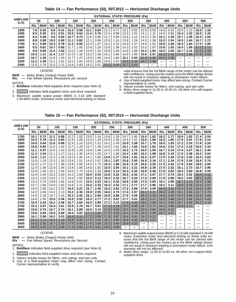
Table 14 — Fan Performance (SI), 50TJ012 — Horizontal Discharge Units
AIRFLOW(L/s)
EXTERNAL STATIC PRESSURE (Pa)
50 100 150 200 250 300 350 400 450 500
R/s BkW R/s BkW R/s BkW R/s BkW R/s BkW R/s BkW R/s BkW R/s BkW R/s BkW R/s BkW
1300 7.6 0.30 8.9 0.41 10.2 0.56 11.1 0.64 12.1 0.77 13.1 0.92 13.9 0.93 14.0 0.52 15.0 1.13 15.6 1.321400 8.0 0.40 9.3 0.51 10.5 0.64 11.4 0.75 12.4 0.88 13.3 1.01 14.1 1.11 14.6 0.96 15.4 1.32 16.0 1.421500 8.4 0.48 9.6 0.60 10.7 0.72 11.8 0.86 12.7 0.99 13.5 1.12 14.3 1.26 15.1 1.35 15.7 1.49 16.4 1.541600 8.8 0.58 10.0 0.69 11.1 0.82 12.1 0.96 12.9 1.10 13.8 1.24 14.5 1.38 15.3 1.54 16.0 1.64 16.7 1.721700 9.1 0.69 10.3 0.78 11.3 0.93 12.3 1.07 13.2 1.22 14.0 1.37 14.8 1.52 15.5 1.66 16.3 1.84 17.0 1.951800 9.5 0.81 10.7 0.90 11.7 1.05 12.6 1.20 13.5 1.36 14.3 1.52 15.0 1.67 15.8 1.83 16.4 1.99 17.2 2.171900 9.9 0.95 11.0 1.02 12.0 1.18 12.9 1.34 13.8 1.50 14.6 1.68 15.3 1.83 16.0 2.00 16.7 2.16 17.3 2.332000 10.3 1.11 11.4 1.17 12.3 1.32 13.2 1.48 14.1 1.66 14.9 1.83 15.6 2.01 16.3 2.18 17.0 2.36 17.6 2.532100 10.7 1.29 11.8 1.33 12.7 1.47 13.5 1.65 14.4 1.84 15.1 2.00 15.9 2.20 16.6 2.38 — — — —2200 11.2 1.48 12.1 1.51 13.1 1.64 13.9 1.83 14.6 2.01 15.4 2.20 16.2 2.38 — — — — — —2300 11.6 1.70 12.5 1.71 13.4 1.83 14.2 2.01 15.0 2.20 15.7 2.41 — — — — — — — —
LEGEND
BkW — Motor Brake (Output) Power (kW)R/s — Fan Wheel Speed, Revolutions per second
NOTES:1. Boldface indicates field-supplied drive required (see Note 6).
2. indicates field-supplied motor and drive required.3. Maximum usable output power (BkW) is 2.16 with standard
1.50-BkW motor. Extensive motor and electrical testing on these
units ensures that the full BkW range of the motor can be utilizedwith confidence. Using your fanmotors up to the BkW ratings shownwill not result in nuisance tripping or premature motor failure.
4. Use of field-supplied motor may affect wire sizing. Contact Carrierrepresentative to verify.
5. Values include losses for filters, unit casing, and wet coils.6. Motor drive range is 11.50 to 15.00 r/s. All other r/s’s will require
a field-supplied drive.
Table 15 — Fan Performance (SI), 50TJ014 — Horizontal Discharge Units
AIRFLOW(L/s)
EXTERNAL STATIC PRESSURE (Pa)
50 100 150 200 250 300 350 400 450 500
R/s BkW R/s BkW R/s BkW R/s BkW R/s BkW R/s BkW R/s BkW R/s BkW R/s BkW R/s BkW
1750 10.1 0.72 11.2 0.88 12.2 1.02 13.0 1.16 13.9 1.29 14.7 1.45 15.5 1.62 16.2 1.77 16.9 1.92 17.4 2.041800 10.4 0.78 11.4 0.93 12.4 1.08 13.3 1.24 14.0 1.36 14.8 1.51 15.6 1.69 16.3 1.85 17.0 2.01 17.6 2.141850 10.6 0.84 11.6 0.98 12.5 1.14 13.5 1.31 14.2 1.43 15.0 1.58 15.7 1.76 16.5 1.93 17.2 2.10 17.8 2.241900 10.8 0.90 11.8 1.04 12.7 1.20 13.7 1.39 14.4 1.51 15.1 1.65 15.8 1.83 16.6 2.01 17.3 2.18 18.0 2.341950 11.1 0.97 12.0 1.10 12.9 1.28 13.8 1.46 14.5 1.59 15.3 1.73 16.0 1.90 16.7 2.10 17.4 2.27 18.1 2.442000 11.3 1.04 12.1 1.17 13.1 1.35 14.0 1.53 14.7 1.68 15.4 1.82 16.2 1.98 16.8 2.18 17.5 2.36 18.2 2.542050 11.6 1.11 12.3 1.24 13.2 1.42 14.1 1.60 14.9 1.77 15.6 1.91 16.3 2.07 17.0 2.26 17.6 2.45 18.3 2.632100 11.9 1.19 12.5 1.30 13.4 1.51 14.3 1.67 15.1 1.87 15.8 2.00 16.5 2.16 17.1 2.34 17.8 2.54 18.4 2.742150 12.0 1.27 12.7 1.38 13.6 1.58 14.5 1.75 15.3 1.96 15.9 2.10 16.6 2.25 17.3 2.42 17.9 2.64 18.6 2.842200 12.4 1.36 12.9 1.46 13.8 1.66 14.6 1.83 15.5 2.05 16.1 2.21 16.8 2.36 17.4 2.52 18.1 2.73 18.7 2.952250 12.6 1.45 13.1 1.54 14.0 1.74 14.8 1.93 15.6 2.14 16.3 2.32 16.9 2.46 17.6 2.62 18.2 2.83 18.8 3.052300 12.9 1.54 13.3 1.63 14.2 1.83 15.0 2.03 15.8 2.22 16.5 2.43 17.1 2.57 17.7 2.74 18.4 2.92 19.0 3.152350 13.2 1.63 13.5 1.72 14.4 1.92 15.2 2.13 16.0 2.32 16.7 2.54 17.3 2.69 17.9 2.86 18.5 3.03 19.1 3.252400 13.4 1.73 13.8 1.81 14.6 2.01 15.4 2.23 16.1 2.42 16.9 2.65 17.5 2.83 18.1 2.98 18.7 3.15 19.3 3.362450 13.7 1.84 14.0 1.92 14.8 2.11 15.5 2.33 16.3 2.52 17.1 2.77 17.7 2.95 18.2 3.11 18.8 3.28 19.4 3.472500 14.0 1.95 14.2 2.02 15.0 2.21 15.7 2.45 16.5 2.63 17.2 2.86 17.9 3.09 18.4 3.24 19.0 3.42 19.6 3.592550 14.2 2.06 14.5 2.13 15.2 2.30 15.9 2.55 16.6 2.75 17.4 2.97 18.1 3.21 18.6 3.38 19.1 3.55 19.7 3.742600 14.5 2.18 14.7 2.24 15.3 2.42 16.1 2.66 16.8 2.88 17.5 3.09 18.3 3.35 18.8 3.53 19.3 3.69 19.9 3.882650 14.8 2.30 15.0 2.36 15.5 2.52 16.3 2.77 17.2 3.01 17.7 3.01 18.4 3.47 19.0 3.68 19.5 3.84 20.0 4.032700 15.0 2.43 15.2 2.48 15.7 2.64 16.5 2.89 17.2 3.13 17.9 3.33 18.6 3.59 19.2 3.83 19.7 4.00 20.2 4.182750 15.3 2.57 15.4 2.61 15.9 2.76 16.7 3.01 17.4 3.19 18.0 3.46 18.7 3.71 19.4 3.98 19.9 4.17 — —2800 15.6 2.70 15.7 2.74 16.1 2.89 16.9 3.13 17.6 3.40 18.2 3.61 20.5 3.84 19.6 4.13 — — — —2850 15.8 2.84 15.9 2.89 16.4 3.02 17.1 3.26 17.8 3.53 18.4 3.76 19.0 3.98 19.7 4.27 — — — —2900 16.1 2.99 16.2 3.03 16.6 3.15 17.3 3.39 17.9 3.67 18.6 3.91 19.2 4.12 — — — — — —2950 16.4 3.14 16.5 3.18 16.8 3.30 17.5 3.53 18.1 3.80 18.8 4.06 19.4 4.27 — — — — — —3000 16.6 3.30 16.7 3.33 17.0 3.45 17.6 3.66 18.3 3.94 18.9 4.22 — — — — — — — —3050 16.9 3.46 17.0 3.49 17.3 3.60 17.8 3.81 18.5 4.09 — — — — — — — — — —
LEGEND
BkW — Motor Brake (Output) Power (kW)R/s — Fan Wheel Speed, Revolutions per Second
NOTES:1. Boldface indicates field-supplied drive required (see Note 6).
2. indicates field-supplied motor and drive required.3. Values include losses for filters, unit casing, and wet coils.4. Use of a field-supplied motor may affect wire sizing. Contact
Carrier representative to verify.
5. Maximumusable output power (BkW) is 3.13 with standard 2.24-kWmotor. Extensive motor and electrical testing on these units en-sures that the full BkW range of the motor can be utilized withconfidence. Using your fan motors up to the BkW ratings shownwill not result in nuisance tripping or premature motor failure. Unitwarranty will not be affected.
6. Motor drive range: 11.83 to 14.83 r/s. All other r/s’s require field-supplied drive.
24

Table 16 — Fan Performance (English), 50TJ007 — Vertical Discharge Units
AIRFLOW(Cfm)
EXTERNAL STATIC PRESSURE (in. wg)
0.1 0.2 0.4 0.6 0.8 1.0 1.2 1.4 1.6
Rpm Bhp Rpm Bhp Rpm Bhp Rpm Bhp Rpm Bhp Rpm Bhp Rpm Bhp Rpm Bhp Rpm Bhp
1800 852 0.55 905 0.62 1002 0.78 1084 0.93 1163 1.10 1235 1.29 1303 1.48 1371 1.69 1433 1.901900 894 0.64 945 0.72 1037 0.88 1119 1.04 1194 1.21 1266 1.40 1330 1.59 1396 1.81 1460 2.032000 936 0.74 984 0.82 1072 0.98 1154 1.16 1226 1.33 1297 1.53 1362 1.73 1422 1.94 1485 2.162100 978 0.85 1024 0.93 1108 1.10 1190 1.29 1259 1.47 1327 1.66 1393 1.87 1452 2.08 1510 2.312200 1021 0.97 1064 1.05 1145 1.22 1225 1.43 1294 1.62 1359 1.81 1423 2.02 1483 2.24 1536 2.462300 1064 1.10 1104 1.18 1183 1.36 1260 1.57 1330 1.78 1392 1.97 1454 2.18 1515 2.41 1569 2.642400 1107 1.24 1145 1.32 1222 1.52 1296 1.73 1365 1.94 1426 2.15 1485 2.36 1544 2.59 1601 2.842500 1150 1.39 1166 1.48 1262 1.68 1331 1.89 1400 2.12 1461 2.34 1518 2.55 1575 2.78 — —2600 1193 1.56 1228 1.65 1301 1.86 1367 2.07 1435 2.31 1497 2.54 1552 2.76 — — — —2700 1237 1.74 1269 1.83 1341 2.05 1404 2.26 1471 2.51 1532 2.75 — — — — — —2800 1280 1.94 1311 2.03 1381 2.25 1442 2.47 1506 2.72 — — — — — — — —2900 1324 2.15 1354 2.24 1420 2.47 1481 2.69 1542 2.94 — — — — — — — —3000 1368 2.37 1396 2.46 1460 2.69 1521 2.93 — — — — — — — — — —
LEGEND
Bhp — Brake HorsepowerRpm — Fan Wheel Speed, Revolutions per MinuteNOTES:1. Boldface indicates field-supplied drive required (see Note 6).
2. indicates field-supplied motor and drive required.3. Maximum usable bhp is 2.40 with standard 1.5-hp motor. Exten-
sive motor and electrical testing on these units ensures that the
full horsepower range of the motor can be utilized with confi-dence. Using your fan motors up to the BkW ratings shown willnot result in nuisance tripping or premature motor failure.
4. Use of field-supplied motor may affect wire sizing. Contact Carrierrepresentative to verify.
5. Values include losses for filters, unit casing, and wet coils.6. Motor drive range is 930 to 1205 rpm. All other rpm’s will require
a field-supplied drive.
Table 17 — Fan Performance (English), 50TJ008,009 — Vertical Discharge Units
AIRFLOW(Cfm)
EXTERNAL STATIC PRESSURE (in. wg)
0.2 0.4 0.6 0.8 1.0 1.2 1.4 1.6 1.8 2.0
Rpm Bhp Rpm Bhp Rpm Bhp Rpm Bhp Rpm Bhp Rpm Bhp Rpm Bhp Rpm Bhp Rpm Bhp Rpm Bhp
2200 503 0.50 585 0.71 653 0.92 716 1.15 772 1.38 824 1.63 884 1.95 934 2.30 916 2.64 1019 3.092400 534 0.61 613 0.84 677 1.06 738 1.30 794 1.55 844 1.81 892 2.08 944 2.40 987 2.76 1039 3.202600 565 0.74 639 0.97 703 1.20 761 1.46 816 1.74 866 2.01 913 2.29 957 2.58 1004 2.91 1050 3.312800 597 0.89 665 1.12 731 1.40 786 1.66 839 1.93 889 2.23 935 2.52 978 2.62 1019 3.13 1061 3.473000 629 1.06 694 1.29 759 1.59 812 1.88 862 2.15 911 2.46 957 2.78 1000 3.09 1040 3.41 — —3200 662 1.25 724 1.50 785 1.80 840 2.11 887 2.41 934 2.71 980 3.04 1022 3.38 — — — —3400 696 1.46 756 1.73 811 2.02 868 2.37 914 2.69 959 3.00 1003 3.32 — — — — — —3600 729 1.69 787 1.98 839 2.27 894 2.64 942 2.99 984 3.32 — — — — — — — —3800 763 1.95 819 2.27 869 2.56 920 2.92 970 3.31 — — — — — — — — — —
LEGEND
Bhp — Brake HorsepowerRpm — Fan Wheel Speed, Revolutions per Minute
NOTES:1. Boldface indicates field-supplied drive required (see Note 6).
2. indicates field-supplied motor and drive required.3. Maximum usable bhp is 2.40 with standard 1.5-hp motor. Exten-
sive motor and electrical testing on these units ensures that the
full horsepower range of the motor can be utilized with confi-dence. Using your fan motors up to the horsepower ratings shownwill not result in nuisance tripping or premature motor failure.
4. Use of field-supplied motor may affect wire sizing. Contact Carrierrepresentative to verify.
5. Values include losses for filters, unit casing, and wet coils.6. Motor drive range is 620 to 880 rpm. All other rpm’s will require a
field-supplied drive.
25

Table 18 — Fan Performance (English), 50TJ012 — Vertical Discharge Units
AIRFLOW(Cfm)
EXTERNAL STATIC PRESSURE (in. wg)
0.2 0.4 0.6 0.8 1.0 1.2 1.4 1.6 1.8 2.0
Rpm Bhp Rpm Bhp Rpm Bhp Rpm Bhp Rpm Bhp Rpm Bhp Rpm Bhp Rpm Bhp Rpm Bhp Rpm Bhp
3000 532 0.64 605 0.81 670 0.97 725 1.12 778 1.28 825 1.43 874 1.60 926 1.82 974 2.11 1012 2.363200 557 0.75 628 0.93 690 1.10 746 1.28 796 1.44 844 1.61 888 1.70 934 1.94 988 2.18 1025 2.473400 583 0.88 651 1.06 711 1.25 767 1.44 815 1.61 863 1.79 907 1.97 947 2.14 991 2.32 1038 2.573600 609 1.01 674 1.22 732 1.42 787 1.61 836 1.80 880 1.98 926 2.18 966 2.36 1004 2.54 1045 2.743800 535 1.16 698 1.39 755 1.59 808 1.80 857 2.01 901 2.20 943 2.39 985 2.60 1023 2.79 1059 2.984000 662 1.33 722 1.57 778 1.78 829 2.01 878 2.22 922 2.44 962 2.63 1003 2.84 1042 3.06 1078 3.264200 689 1.52 746 1.77 801 1.99 851 2.23 898 2.45 943 2.69 983 2.91 1021 3.11 1060 3.34 — —4400 715 1.72 772 1.99 825 2.22 873 2.46 919 2.71 963 2.94 1004 3.19 1042 3.41 — — — —4600 742 1.94 797 2.22 848 2.48 896 2.72 940 2.98 984 3.22 1025 3.48 — — — — — —4800 770 2.18 823 2.46 872 2.75 919 3.00 963 3.27 — — — — — — — — — —5000 797 2.44 849 2.73 897 3.04 943 3.30 — — — — — — — — — — — —
LEGEND
Bhp — Brake HorsepowerRpm — Fan Wheel Speed, Revolutions per Minute
NOTES:1. Boldface indicates field-supplied drive required (see Note 6).
2. indicates field-supplied motor and drive required.3. Maximum usable bhp is 2.90 with standard 2.0-hp motor. Exten-
sive motor and electrical testing on these units ensures that the
full horsepower range of the motor can be utilized with confi-dence. Using your fan motors up to the horsepower ratings shownwill not result in nuisance tripping or premature motor failure.
4. Use of field-supplied motor may affect wire sizing. Contact Carrierrepresentative to verify.
5. Values include losses for filters, unit casing, and wet coils.6. Motor drive range is 690 to 900 rpm. All other rpm’s will require a
field-supplied drive.
Table 19 — Fan Performance (English), 50TJ014 — Vertical Discharge Units
AIRFLOW(Cfm)
EXTERNAL STATIC PRESSURE (in. wg)
0.2 0.4 0.6 0.8 1.0 1.2 1.4 1.6 1.8 2.0
Rpm Bhp Rpm Bhp Rpm Bhp Rpm Bhp Rpm Bhp Rpm Bhp Rpm Bhp Rpm Bhp Rpm Bhp Rpm Bhp
3700 654 1.12 714 1.31 767 1.50 815 1.67 861 1.85 906 2.08 950 2.27 991 2.47 1030 2.65 1064 2.823800 668 1.20 727 1.40 780 1.60 827 1.77 873 1.95 916 2.18 959 2.38 1001 2.58 1040 2.78 1075 2.963900 683 1.28 741 1.49 793 1.70 839 1.88 884 2.05 927 2.28 969 2.50 1010 2.70 1049 2.91 1085 3.114000 697 1.37 754 1.59 806 1.80 851 1.99 895 2.16 938 2.38 979 2.62 1020 2.83 1059 3.04 1095 3.254100 711 1.46 767 1.69 819 1.90 864 2.10 907 2.28 949 2.49 989 2.74 1029 2.96 1068 3.18 1105 3.394200 726 1.56 780 1.80 832 2.01 877 2.22 919 2.41 960 2.60 1000 2.86 1039 3.10 1077 3.31 1114 3.544300 741 1.66 794 1.91 845 2.12 889 2.35 931 2.54 971 2.72 1011 2.97 1049 3.23 1087 3.46 1124 3.694400 755 1.77 808 2.03 858 2.24 902 2.48 943 2.68 983 2.86 1022 3.10 1059 3.37 1097 3.61 1133 3.844500 770 1.89 821 2.15 871 2.37 915 2.61 955 2.82 995 3.01 1033 3.23 1070 3.51 1107 3.76 1143 4.004600 784 2.00 835 2.27 884 2.49 928 2.75 968 2.96 1006 3.17 1044 3.37 1081 3.64 1117 3.92 1152 4.174700 799 2.13 849 2.40 897 2.63 941 2.88 981 3.11 1018 3.32 1056 3.52 1092 3.78 1127 4.07 1162 4.334800 814 2.25 863 2.53 910 2.77 954 3.02 993 3.27 1030 3.48 1067 3.69 1103 3.93 1138 4.23 1172 4.504900 829 2.39 877 2.67 923 2.92 967 3.17 1006 3.43 1043 3.65 1079 3.87 1114 4.09 1149 4.37 1182 4.685000 843 2.52 892 2.81 937 3.08 980 3.32 1019 3.60 1055 3.82 1091 4.05 1126 4.25 1160 4.53 1193 4.855100 858 2.67 906 2.95 950 3.24 993 3.48 1032 3.76 1068 4.00 1103 4.23 1137 4.45 1171 4.70 1204 5.015200 873 2.82 920 3.10 963 3.40 1006 3.65 1045 3.93 1081 4.19 1115 4.42 1149 4.65 1182 4.88 1215 5.185300 888 2.97 934 3.26 977 3.57 1019 3.82 1058 4.11 1094 4.38 1127 4.62 1161 4.85 1194 5.07 1226 5.365400 903 3.13 949 3.43 991 3.75 1032 4.00 1071 4.29 1106 4.57 1139 4.82 1173 5.06 1205 5.29 1237 5.555500 918 3.30 963 3.59 1004 3.92 1045 4.18 1084 4.47 1119 4.77 1152 5.03 1185 5.27 1217 5.51 1248 5.755600 933 3.47 978 3.77 1018 4.11 1058 4.38 1097 4.66 1132 4.97 1165 5.24 1197 5.49 1229 5.74 — —5700 948 3.65 992 3.95 1032 4.30 1072 4.58 1110 4.86 1145 5.18 1178 5.46 1209 5.72 — — — —5800 963 3.83 1006 4.14 1046 4.50 1085 4.79 1123 5.07 1158 5.39 1191 5.69 — — — — — —5900 978 4.00 1021 4.34 1060 4.69 1098 5.01 1136 5.28 1171 5.60 — — — — — — — —6000 993 4.22 1035 4.54 1074 4.89 1112 5.23 1149 5.50 — — — — — — — — — —6100 1008 4.42 1050 4.75 1089 5.10 1125 5.45 1162 5.73 — — — — — — — — — —6200 1023 4.63 1065 4.96 1103 5.32 1139 5.68 — — — — — — — — — — — —6300 1038 4.85 1079 5.19 1117 5.54 — — — — — — — — — — — — — —
LEGEND
Bhp — Brake HorsepowerRpm — Fan Wheel Speed, Revolutions per Minute
NOTES:1. Boldface indicates field-supplied drive required (see Note 6).
2. indicates field-supplied motor and drive required.3. Values include losses for filters, unit casing, and wet coils.4. Use of a field-supplied motor may affect wire sizing. Contact
Carrier representative to verify.
5. Maximum usable bhp is 4.2 with standard 3.0 Hp motor. Exten-sive motor and electrical testing on these units ensures that thefull horsepower range of the motor can be utilized with confi-dence. Using your fan motors up to the horsepower ratings shownwill not result in nuisance tripping or premature motor failure. Unitwarranty will not be affected.
6. Motor drive range: 710 to 890 rpm. All other rpms require field-supplied drive.
26

Table 20 — Fan Performance (English), 50TJ007 — Horizontal Discharge Units
AIRFLOW(Cfm)
EXTERNAL STATIC PRESSURE (in. wg)
0.1 0.2 0.4 0.6 0.8 1.0 1.2 1.4 1.6
Rpm Bhp Rpm Bhp Rpm Bhp Rpm Bhp Rpm Bhp Rpm Bhp Rpm Bhp Rpm Bhp Rpm Bhp
1800 765 0.45 821 0.51 923 0.65 1019 0.81 1099 0.96 1178 1.14 1249 1.32 1316 1.52 1382 1.721900 802 0.52 854 0.58 953 0.73 1046 0.90 1126 1.06 1201 1.23 1274 1.43 1338 1.62 1402 1.832000 840 0.60 888 0.66 984 0.82 1073 0.99 1154 1.16 1226 1.33 1297 1.53 1363 1.73 1424 1.942100 876 0.69 923 0.75 1015 0.91 1101 1.08 1182 1.27 1252 1.45 1320 1.64 1386 1.85 1448 2.072200 916 0.76 958 0.85 1046 1.01 1129 1.19 1209 1.39 1280 1.58 1345 1.77 1410 1.97 1473 2.202300 954 0.89 993 0.96 1079 1.13 1160 1.31 1237 1.51 1309 1.71 1372 1.91 1434 2.11 1496 2.342400 993 1.00 1029 1.07 1112 1.25 1190 1.43 1264 1.63 1336 1.85 1400 2.06 1459 2.26 1519 2.462500 1031 1.13 1066 1.20 1145 1.39 1220 1.57 1292 1.77 1363 2.00 1428 2.22 1486 2.43 1543 2.652600 1070 1.26 1103 1.34 1179 1.52 1251 1.71 1322 1.92 1390 2.15 1456 2.38 1514 2.61 1569 2.832700 1109 1.41 1140 1.48 1212 1.67 1283 1.87 1352 2.09 1418 2.31 1483 2.56 1543 2.80 — —2800 1148 1.57 1177 1.64 1246 1.83 1316 2.04 1383 2.26 1446 2.48 1510 2.73 — — — —2900 1188 1.74 1215 1.81 1281 2.00 1349 2.22 1413 2.44 1476 2.67 1537 2.92 — — — —3000 1227 1.92 1253 2.00 1316 2.19 1382 2.42 1444 2.63 1506 2.88 — — — — — —
LEGEND
Bhp — Brake HorsepowerRpm — Fan Wheel Speed, Revolutions per Minute
NOTES:1. Boldface indicates field-supplied drive required (see Note 6).
2. indicates field-supplied motor and drive required.3. Maximum usable bhp is 2.40 with standard 1.5-hp motor. Exten-
sive motor and electrical testing on these units ensures that the
full horsepower range of the motor can be utilized with confi-dence. Using your fan motors up to the horsepower ratings shownwill not result in nuisance tripping or premature motor failure.
4. Use of field-supplied motor may affect wire sizing. Contact Carrierrepresentative to verify.
5. Values include losses for filters, unit casing, and wet coils.6. Motor drive range is 930 to 1205 rpm. All other rpm’s will require
a field-supplied drive.
Table 21 — Fan Performance (English), 50TJ008,009 — Horizontal Discharge Units
AIRFLOW(Cfm)
EXTERNAL STATIC PRESSURE (in. wg)
0.2 0.4 0.6 0.8 1.0 1.2 1.4 1.6 1.8 2.0
Rpm Bhp Rpm Bhp Rpm Bhp Rpm Bhp Rpm Bhp Rpm Bhp Rpm Bhp Rpm Bhp Rpm Bhp Rpm Bhp
2200 459 0.42 549 0.62 625 0.83 691 1.06 753 1.31 805 1.58 842 1.87 857 2.16 851 2.45 823 2.702400 482 0.50 569 0.71 645 0.95 708 1.18 768 1.40 824 1.72 872 2.01 909 2.32 931 2.64 935 2.962600 507 0.59 592 0.82 663 1.08 727 1.32 784 1.58 839 1.87 891 2.17 936 2.49 973 2.82 999 3.162800 533 0.71 615 0.95 683 1.20 747 1.49 802 1.75 855 2.04 906 2.35 954 2.67 997 3.01 1034 3.363000 559 0.83 637 1.09 704 1.35 765 1.66 823 1.94 872 2.22 921 2.54 969 2.88 1014 3.22 — —3200 585 0.96 660 1.24 727 1.52 785 1.83 841 2.15 892 2.45 939 2.76 984 3.10 — — — —3400 610 1.10 682 1.41 750 1.72 806 2.01 860 2.36 912 2.69 958 3.01 1002 3.34 — — — —3600 636 1.25 707 1.60 772 1.93 828 2.23 880 2.57 930 2.95 978 3.29 — — — — — —3800 661 1.41 733 1.82 795 2.15 852 2.48 901 2.80 949 3.20 — — — — — — — —
LEGEND
Bhp — Brake HorsepowerRpm — Fan Wheel Speed, Revolutions per Minute
NOTES:1. Boldface indicates field-supplied drive required (see Note 6).
2. indicates field-supplied motor and drive required.3. Maximum usable bhp is 2.40 with standard 1.5-hp motor. Exten-
sive motor and electrical testing on these units ensures that the
full horsepower range of the motor can be utilized with confi-dence. Using your fan motors up to the horsepower ratings shownwill not result in nuisance tripping or premature motor failure.
4. Use of field-supplied motor may affect wire sizing. Contact Carrierrepresentative to verify.
5. Values include losses for filters, unit casing, and wet coils.6. Motor drive range is 620 to 880 rpm. All other rpm’s will require a
field-supplied drive.
27
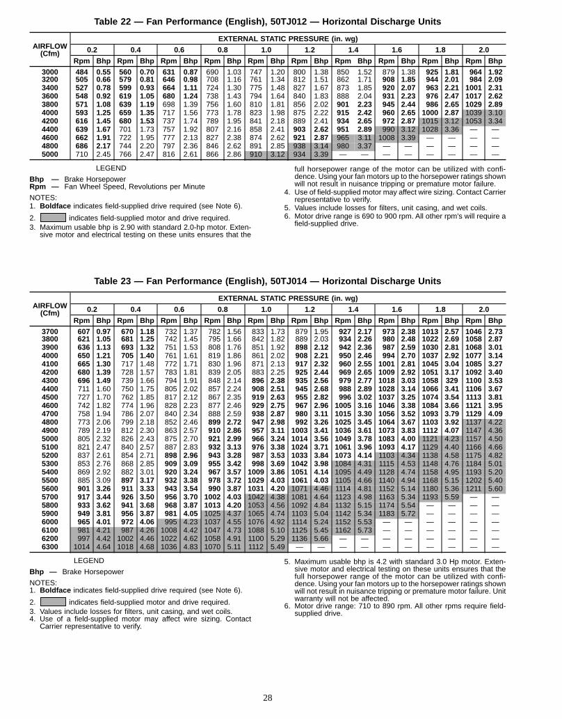
Table 22 — Fan Performance (English), 50TJ012 — Horizontal Discharge Units
AIRFLOW(Cfm)
EXTERNAL STATIC PRESSURE (in. wg)
0.2 0.4 0.6 0.8 1.0 1.2 1.4 1.6 1.8 2.0
Rpm Bhp Rpm Bhp Rpm Bhp Rpm Bhp Rpm Bhp Rpm Bhp Rpm Bhp Rpm Bhp Rpm Bhp Rpm Bhp
3000 484 0.55 560 0.70 631 0.87 690 1.03 747 1.20 800 1.38 850 1.52 879 1.38 925 1.81 964 1.923200 505 0.66 579 0.81 646 0.98 708 1.16 761 1.34 812 1.51 862 1.71 908 1.85 944 2.01 984 2.093400 527 0.78 599 0.93 664 1.11 724 1.30 775 1.48 827 1.67 873 1.85 920 2.07 963 2.21 1001 2.313600 548 0.92 619 1.05 680 1.24 738 1.43 794 1.64 840 1.83 888 2.04 931 2.23 976 2.47 1017 2.623800 571 1.08 639 1.19 698 1.39 756 1.60 810 1.81 856 2.02 901 2.23 945 2.44 986 2.65 1029 2.894000 593 1.25 659 1.35 717 1.56 773 1.78 823 1.98 875 2.22 915 2.42 960 2.65 1000 2.87 1039 3.104200 616 1.45 680 1.53 737 1.74 789 1.95 841 2.18 889 2.41 934 2.65 972 2.87 1015 3.12 1053 3.344400 639 1.67 701 1.73 757 1.92 807 2.16 858 2.41 903 2.62 951 2.89 990 3.12 1028 3.36 — —4600 662 1.91 722 1.95 777 2.13 827 2.38 874 2.62 921 2.87 965 3.11 1008 3.39 — — — —4800 686 2.17 744 2.20 797 2.36 846 2.62 891 2.85 938 3.14 980 3.37 — — — — — —5000 710 2.45 766 2.47 816 2.61 866 2.86 910 3.12 934 3.39 — — — — — — — —
LEGEND
Bhp — Brake HorsepowerRpm — Fan Wheel Speed, Revolutions per Minute
NOTES:1. Boldface indicates field-supplied drive required (see Note 6).
2. indicates field-supplied motor and drive required.3. Maximum usable bhp is 2.90 with standard 2.0-hp motor. Exten-
sive motor and electrical testing on these units ensures that the
full horsepower range of the motor can be utilized with confi-dence. Using your fan motors up to the horsepower ratings shownwill not result in nuisance tripping or premature motor failure.
4. Use of field-supplied motor may affect wire sizing. Contact Carrierrepresentative to verify.
5. Values include losses for filters, unit casing, and wet coils.6. Motor drive range is 690 to 900 rpm. All other rpm’s will require a
field-supplied drive.
Table 23 — Fan Performance (English), 50TJ014 — Horizontal Discharge Units
AIRFLOW(Cfm)
EXTERNAL STATIC PRESSURE (in. wg)
0.2 0.4 0.6 0.8 1.0 1.2 1.4 1.6 1.8 2.0
Rpm Bhp Rpm Bhp Rpm Bhp Rpm Bhp Rpm Bhp Rpm Bhp Rpm Bhp Rpm Bhp Rpm Bhp Rpm Bhp
3700 607 0.97 670 1.18 732 1.37 782 1.56 833 1.73 879 1.95 927 2.17 973 2.38 1013 2.57 1046 2.733800 621 1.05 681 1.25 742 1.45 795 1.66 842 1.82 889 2.03 934 2.26 980 2.48 1022 2.69 1058 2.873900 636 1.13 693 1.32 751 1.53 808 1.76 851 1.92 898 2.12 942 2.36 987 2.59 1030 2.81 1068 3.014000 650 1.21 705 1.40 761 1.61 819 1.86 861 2.02 908 2.21 950 2.46 994 2.70 1037 2.92 1077 3.144100 665 1.30 717 1.48 772 1.71 830 1.96 871 2.13 917 2.32 960 2.55 1001 2.81 1045 3.04 1085 3.274200 680 1.39 728 1.57 783 1.81 839 2.05 883 2.25 925 2.44 969 2.65 1009 2.92 1051 3.17 1092 3.404300 696 1.49 739 1.66 794 1.91 848 2.14 896 2.38 935 2.56 979 2.77 1018 3.03 1058 329 1100 3.534400 711 1.60 750 1.75 805 2.02 857 2.24 908 2.51 945 2.68 988 2.89 1028 3.14 1066 3.41 1106 3.674500 727 1.70 762 1.85 817 2.12 867 2.35 919 2.63 955 2.82 996 3.02 1037 3.25 1074 3.54 1113 3.814600 742 1.82 774 1.96 828 2.23 877 2.46 929 2.75 967 2.96 1005 3.16 1046 3.38 1084 3.66 1121 3.954700 758 1.94 786 2.07 840 2.34 888 2.59 938 2.87 980 3.11 1015 3.30 1056 3.52 1093 3.79 1129 4.094800 773 2.06 799 2.18 852 2.46 899 2.72 947 2.98 992 3.26 1025 3.45 1064 3.67 1103 3.92 1137 4.224900 789 2.19 812 2.30 863 2.57 910 2.86 957 3.11 1003 3.41 1036 3.61 1073 3.83 1112 4.07 1147 4.365000 805 2.32 826 2.43 875 2.70 921 2.99 966 3.24 1014 3.56 1049 3.78 1083 4.00 1121 4.23 1157 4.505100 821 2.47 840 2.57 887 2.83 932 3.13 976 3.38 1024 3.71 1061 3.96 1093 4.17 1129 4.40 1166 4.665200 837 2.61 854 2.71 898 2.96 943 3.28 987 3.53 1033 3.84 1073 4.14 1103 4.34 1138 4.58 1175 4.825300 853 2.76 868 2.85 909 3.09 955 3.42 998 3.69 1042 3.98 1084 4.31 1115 4.53 1148 4.76 1184 5.015400 869 2.92 882 3.01 920 3.24 967 3.57 1009 3.86 1051 4.14 1095 4.49 1128 4.74 1158 4.95 1193 5.205500 885 3.09 897 3.17 932 3.38 978 3.72 1029 4.03 1061 4.03 1105 4.66 1140 4.94 1168 5.15 1202 5.405600 901 3.26 911 3.33 943 3.54 990 3.87 1031 4.20 1071 4.46 1114 4.81 1152 5.14 1180 5.36 1211 5.605700 917 3.44 926 3.50 956 3.70 1002 4.03 1042 4.38 1081 4.64 1123 4.98 1163 5.34 1193 5.59 — —5800 933 3.62 941 3.68 968 3.87 1013 4.20 1053 4.56 1092 4.84 1132 5.15 1174 5.54 — — — —5900 949 3.81 956 3.87 981 4.05 1025 4.37 1065 4.74 1103 5.04 1142 5.34 1183 5.72 — — — —6000 965 4.01 972 4.06 995 4.23 1037 4.55 1076 4.92 1114 5.24 1152 5.53 — — — — — —6100 981 4.21 987 4.26 1008 4.42 1047 4.73 1088 5.10 1125 5.45 1162 5.73 — — — — — —6200 997 4.42 1002 4.46 1022 4.62 1058 4.91 1100 5.29 1136 5.66 — — — — — — — —6300 1014 4.64 1018 4.68 1036 4.83 1070 5.11 1112 5.49 — — — — — — — — — —
LEGEND
Bhp — Brake Horsepower
NOTES:1. Boldface indicates field-supplied drive required (see Note 6).
2. indicates field-supplied motor and drive required.3. Values include losses for filters, unit casing, and wet coils.4. Use of a field-supplied motor may affect wire sizing. Contact
Carrier representative to verify.
5. Maximum usable bhp is 4.2 with standard 3.0 Hp motor. Exten-sive motor and electrical testing on these units ensures that thefull horsepower range of the motor can be utilized with confi-dence. Using your fan motors up to the horsepower ratings shownwill not result in nuisance tripping or premature motor failure. Unitwarranty will not be affected.
6. Motor drive range: 710 to 890 rpm. All other rpms require field-supplied drive.
28

START-UP
Unit Preparation — Make sure that unit has been in-stalled in accordance with installation instructions and ap-plicable codes.
Return-Air Filters — Make sure correct filters are in-stalled in unit (see Tables 1A and 1B). Do not operate unitwithout return-air filters.
Compressor Mounting — Compressors are inter-nally spring mounted. Do not loosen or remove compressorholddown bolts. Remove the tie-down bands that hold thecompressors together on 50TJ014 units.
Internal Wiring — Check all electrical connections inunit control boxes; tighten as required.
Refrigerant Service Ports — Each refrigerant sys-tem has 4 Schrader-type service ports: one on the suctionline, one on the liquid line, and 2 on the compressor dis-charge line. Be sure that caps on the ports are tight.
NOTE: When the controls upgrade package is used, oneSchrader-type valve is located under both the high-pressureand low-pressure switches.
Compressor Rotation — On 50TJ007 and 014 scrollcompressor units, it is important to be certain compressor isrotating in the proper direction. To determine whether or notcompressor is rotating in the proper direction:1. Connect service gages to suction and discharge pressure
fittings.2. Energize the compressor.3. The suction pressure should drop and the discharge pres-
sure should rise, as is normal on any start-up.If the suction pressure does not drop and the discharge
pressure does not rise to normal levels:1. Note that the evaporator fan is probably also rotating in
the wrong direction.2. Turn off power to the unit.3. Reverse any two of the unit power leads.4. Reapply power to the compressor.The suction and discharge pressure levels should nowmove
to their normal start-up levels.
NOTE: When the compressor is rotating in the wrongdirection, the unit makes an elevated level of noise and doesnot provide cooling.
Cooling — To start unit, turn on main power supply. Setsystem selector switch at COOL position and fan switch atAUTO. position. Adjust thermostat to a setting below roomtemperature. Compressor starts on closure of contactor.Check unit charge. Refer to Refrigerant Charge section on
page 32.Reset thermostat at a position above room temperature.
Compressor will shut off.
TO SHUT OFF UNIT — Set system selector switch atOFF position. Resetting thermostat at a position above roomtemperature shuts unit off temporarily until space tempera-ture exceeds thermostat setting.
Heating (If Accessory Heater is Installed) — Tostart unit, turn on main power supply.Set thermostat at HEAT position and a setting above room
temperature, and set fan at AUTO. position.First stage of thermostat energizes the first-stage electric
heater; second stage energizes second-stage electric heaterelements if installed.Check heating effects at air-supply grille(s).
If unit does not energize, reset limit switch (located onevaporator-fan scroll) by depressing button located betweenterminals on the switch.
TO SHUT OFF UNIT — Set system selector switch atOFF position. Resetting heating selector lever below roomtemperature will shut off unit temporarily until space tem-perature falls below thermostat setting.
Safety Relief — A soft solder joint in the suction line atthe low-pressure service port provides pressure relief underabnormal temperature and pressure conditions.
Ventilation (Continuous Fan) — Set fan and sys-tem selector switches at ON and OFF positions, respec-tively. Evaporator fan operates continuously to provide aircirculation.
Operating SequenceCOOLING, UNITS WITHOUT ECONOMIZER — Whenthermostat calls for cooling, terminals G and Y1 are ener-gized. The indoor (evaporator) fan contactor (IFC), com-pressor contactor no. 1 (C1), and outdoor (condenser) fanrelay (008-014 only) are energized and evaporator fanmotor, compressor no. 1, and condenser fan start. The condenser-fan motor runs continuously while unit is cooling. If the ther-mostat calls for a second stage of cooling by energizing Y2,compressor contactor no. 2 (C2) is energized and compres-sor no. 2 starts.
HEATING, UNITS WITHOUT ECONOMIZER (If Acces-sory Heater is Installed) — Upon a call for heating throughterminal W1, IFC and heater contactor no. 1 (HC1) are en-ergized. On units equipped for 2 stages of heat, when ad-ditional heat is needed, HC2 is energized through W2.
COOLING, UNITSWITH DURABLADE ECONOMIZERSize 007 —When the outdoor-air temperature is above theOAT (outdoor-air thermostat) setting and the room thermo-stat calls for cooling, the compressor contactor is energizedto start the compressor and outdoor-fan motor. The indoor-fan motor is energized and the economizer damper moves tothe minimum position. After the thermostat is satisfied, thedamper moves to the fully closed position.When the outdoor-air temperature is below the OAT set-
ting and the thermostat calls for cooling, the economizer dampermoves to the minimum position. If the supply-air tempera-ture is above 14 C (57 F), a switch on the supply-air ther-mostat will close between the T2 terminal and the 24 vacterminal. The damper will continue to modulate open untilthe supply-air temperature falls below 13 C (55 F) or thedamper reaches the fully-open position.When the supply-air temperature is between 13 C (55 F)
and 11 C (52 F), switches between the T2 terminal and the24 vac terminal and the T1 terminal and the 24 vac terminalon the supply-air thermostat (SAT) will be open. The damperwill remain in the intermediate open position.If the supply-air temperature falls below 11 C (52 F), the
switch between the T1 terminal and the 24 vac terminal onthe SAT will close. The damper will then modulate closeduntil the supply-air temperature is above 13 C (55 F) or thedamper reaches the minimum position.When the supply-air temperature is between 13 C (55 F)
and 14 C (57 F), switches between the T2 terminal and the24 vac terminal and the T1 terminal and the 24 vac terminalon the SAT will be open. The damper will remain in an in-termediate open position. When the thermostat is satisfied,the damper will move to the fully-closed position.If the outdoor air alone cannot satisfy the cooling require-
ments of the conditioned space, economizer cooling is in-tegrated with mechanical cooling, providing second stage
29

cooling. The compressor and outdoor fan will be energizedand the position of the economizer damper will be deter-mined by the supply-air temperature.When the second stage of cooling is satisfied, the com-
pressor and outdoor-fanmotor will be deenergized. The damperposition will be determined by the supply-air temperature.When the first stage of cooling is satisfied, the damper
will move to fully closed position.Sizes 008-014 —When the outdoor-air temperature is abovethe OAT (outdoor-air thermostat) setting and the room ther-mostat calls for cooling, the compressor contactor no. 1 isenergized to start compressor no. 1 and outdoor-fan motor.The indoor-fanmotor is energized and the economizer dampermoves to the minimum position. Upon a further call for cool-ing, compressor contactor no. 2 will be energized, startingcompressor no. 2.After the thermostat is satisfied, the dampermoves to the fully closed position.When the outdoor-air temperature is below the OAT set-
ting and the thermostat calls for cooling, the economizer dampermoves to the minimum position. If the supply-air tempera-ture is above 14 C (57 F) a switch on the supply-air ther-mostat will close between the T2 terminal and the24 vac terminal. The damper will continue to modulate openuntil the supply-air temperature falls below 13 C (55 F) orthe damper reaches the fully-open position.When the supply-air temperature is between 13 C (55 F)
and 11 C (52 F), switches between the T2 terminal and the24 vac terminal and the T1 terminal and the 24 vac terminalon the supply-air thermostat (SAT) will be open. The damperwill remain in the intermediate open position.If the supply-air temperature falls below 11 C (52 F) the
switch between the T1 terminal and the 24 vac terminal onthe SAT will close. The damper will then modulate closeduntil the supply-air temperature is above 13 C (55 F) or thedamper reaches the minimum position.When the supply-air temperature is between 13 C (55 F)
and 14 C (57 F), switches between the T2 terminal and the24 vac terminal and the T1 terminal and the 24 vac terminalon the SAT will be open. The damper will remain in an in-termediate open position. When the thermostat is satisfied,the damper will move to the fully-closed position.If the outdoor air alone cannot satisfy the cooling require-
ments of the conditioned space, economizer cooling is in-tegrated with mechanical cooling, providing second stagecooling. Compressor no. 1 and outdoor fan will be ener-gized, and the position of the economizer damper will bedetermined by the supply-air temperature. Compressorno. 2 is locked out.When the second stage of cooling is satisfied, the com-
pressor and outdoor fanmotor will be deenergized. The damperposition will be determined by the supply-air temperature.When the first stage of cooling is satisfied, the damper
will move to fully closed position.
HEATING, UNITS WITH ECONOMIZER (If AccessoryHeater is Installed) — When the room thermostat calls forheat through terminal W1, the evaporator-fan contactor andheater contactor no. 1 are energized. On units equipped for2 stages of heat, when additional heat is needed, heater con-tactor no. 2 is energized throughW2. The evaporator-fan mo-tor is energized, and the economizer damper moves to theminimumposition.When the thermostat is satisfied, the dampermoves to the fully closed position.
SERVICE
When servicing unit, shut off all electrical power to unitto avoid shock hazard or injury from rotating parts.
Cleaning— Inspect unit interior at the beginning of eachheating and cooling season and as operating conditionsrequire.
EVAPORATOR COIL1. Turn unit power off. Remove evaporator coil access panel.2. If economizer is installed, remove economizer by dis-
connecting Molex plug and removing economizer mount-ing screws. Refer to Accessory Economizer InstallationInstructions or Optional Durablade Economizer sectionon page 14 for more details.
3. Slide filters out of unit.4. Clean coil using a commercial coil cleaner or dishwasher
detergent in a pressurized spray canister. Wash both sidesof coil and flush with clean water. For best results, back-flush toward return-air section to remove foreign mate-rial. Flush condensate pan after completion.
5. Reinstall economizer and filters.6. Reconnect wiring.7. Replace access panels.
CONDENSER COIL — Inspect coil monthly. Clean con-denser coil annually, or as required by location and outdoor-air conditions.One-Row Coil Cleaning (Size 008 Units)— Wash coil withcommercial coil cleaner. It is not necessary to remove toppanel.Two-Row Coil Cleaning (Size 007 Units)
NOTE: Save all screws removed in this section. The screwsmust be used when reinstalling the equipment.
1. To access 2-row coils, remove screws securing condenser-fan grille to condenser coil top panel. Place grille on topof condenser coil top panel as shown in Fig. 38 and 39.It is not necessary to remove the top panel.
2. Remove 3 screws on right side of compressor access panel.Remove one screw securing condenser coil top panel tocompressor access panel. Remove lower screw securingcondenser coil to compressor mounting plate.
3. Remove 4 screws securing control box access panel. Re-move 3 screws (located in front of the control box ac-cess cover) securing condenser coil top panel.
4. Remove screws securing low-voltage access panel.Remove 2 screws inside low-voltage access panel. Tiltsheet metal (located on left side of low-voltage connec-tions) back 45 degrees.
5. Remove screw securing refrigerant service port accesspanel.
6. Remove 2 U-clips securing 2-row coils together at hair-pin end.
7. Remove screws securing two corner posts. Remove twocorner posts.
8. Use right corner post to prop up right side of condensercoil top panel. Slide condenser coil partially out of con-denser fan housing. See Fig. 39.
30

9. Use left corner post to prop up left side of condensercoil top panel.
10. Carefully separate the outer coil section 76 to 102 mm(3 to 4 in.) from the inner coil section. See Fig. 40.
11. Use a water hose or other suitable equipment to flushdown between the 2 coil sections to remove dirt and de-bris. Clean the outer surfaces with a stiff brush in thenormal manner.
12. Secure inner and outer coils together with U-clips.13. Reposition the outer and inner coil section.14. Reverse the procedure outlined above to reinstall
equipment.
Two-RowCoil Cleaning (Sizes 009-014 Units) —Clean coilsas follows:1. Turn off unit power.2. Remove top panel screws on condenser end of unit.3. Remove condenser coil corner post. See Fig. 41. To hold
top panel open, place coil corner post between top paneland center post. See Fig. 42.
4. Remove screws securing coil to center post.5. Remove fastener holding coil sections together at return
end of condenser coil. Carefully separate the outer coilsection 75 to 100 mm (3 to 4 in.) from the inner coilsection. See Fig. 43.
6. Use a water hose or other suitable equipment to flushdown between the 2 coil sections to remove dirt and de-bris. Clean the outer surfaces with a stiff brush in thenormal manner.
7. Secure inner and outer coil rows together with a field-supplied fastener.
8. Reposition the outer coil section, and remove the coilcorner post between the top panel and center post.
9. Reinstall the coil corner post.10. Replace all screws.
CONDENSATE DRAIN — Check and clean each year atstart of cooling season. In winter, keep drain dry or protectagainst freeze-up.
FILTERS — Clean or replace at start of each heating andcooling season, or more often if operating conditions requireit. Replacement filters must be same dimensions as originalfilters.
Fig. 38 — Condenser Coil, 50TJ007
Fig. 39 — Propping Up Condenser CoilTop Panel
Fig. 40 — Separating Coil Sections
31

LubricationCOMPRESSORS — Each compressor is charged with cor-rect amount of oil at the factory.
FAN-MOTOR BEARINGS —Fan-motor bearings are ofthe permanently lubricated type. No further lubrication isrequired. No lubrication of condenser- or evaporator-fanmotors is required.
Condenser Fan Adjustment (Fig. 44) — Shut offunit power supply. Remove condenser-fan assembly (grille,motor, motor cover, and fan) and loosen fan hub setscrews.Adjust fan height as shown in Fig. 44. Tighten setscrews andreplace condenser-fan assembly.
Refrigerant Charge — Amount of refrigerant chargeis listed on unit nameplate (also refer to Tables 1A and1B). Refer to Carrier GTAC 2-5 Charging, Recovery, Re-cycling, and Reclamation training manual and the followingprocedures.Unit panels must be in place when unit is operating dur-
ing charging procedure.
NO CHARGE—Use standard evacuating techniques. Afterevacuating system, weigh in the specified amount of refrig-erant (refer to Tables 1A and 1B).
LOWCHARGECOOLING—UseCooling Charging Charts,Fig. 45-49. Vary refrigerant until the conditions of the chartsare met. Note the charging charts are different from type nor-mally used. Charts are based on charging the units to thecorrect superheat for the various operating conditions.Accurate pressure gage and temperature sensing device arerequired. Connect the pressure gage to the service port onthe suction line. Mount the temperature sensing device onthe suction line and insulate it so that outdoor ambient tem-perature does not affect the reading. Indoor-air cfm must bewithin the normal operating range of the unit.
TO USECOOLINGCHARGINGCHARTS—Take the out-door ambient temperature and read the suction pressure gage.Refer to charts to determine what suction temperature shouldbe. If suction temperature is high, add refrigerant. If suctiontemperature is low, carefully reclaim some of the charge. Re-check the suction pressure as charge is adjusted.Example: (Fig. 45 Circuit 1)Outdoor Temperature. . . . . . . . . . . . . . . . . . . 24 C (75 F)Suction Pressure. . . . . . . . . . . . . . . . . . 552 kPa (80psig)Suction Temperature should be .. . . . . . . . . . 19 C (66 F)(Suction Temperature may vary62.5 C [5 F])If Chargemastert charging device is used, temperature and
pressure readings must be accomplished using the chargingcharts.
Fig. 41 — Cleaning Condenser Coil
Fig. 42 — Propping Up Top Panel
Fig. 43 — Separating Coil Sections
UNIT 50TJ007-014FAN HEIGHT
Ain. mm
220/240 V 2.75 70400 V 3.50 89
Fig. 44 — Condenser Fan Adjustment
32

Fig. 45 — Cooling Charging Chart, 50TJ007
Fig. 46 — Cooling Charging Chart, 50TJ008
33

Fig. 47 — Cooling Charging Chart, 50TJ009
Fig. 48 — Cooling Charging Chart, 50TJ012
34

Fig. 49 — Cooling Charging Chart, 50TJ014
35

TROUBLESHOOTINGRefer to Table 24 for cooling troubleshooting details.
Table 24 — Cooling Service Analysis
PROBLEM CAUSE REMEDYCompressor(s) andcondenser fan will notstart.
Power failure. Call power company.Fuse blown or circuit breaker tripped. Replace fuse or reset circuit breaker.Defective thermostat, contactor, transformer, or controlrelay.
Replace component.
Insufficient line voltage. Determine cause and correct.Incorrect or faulty wiring. Check wiring diagram and rewire correctly.Thermostat setting too high. Lower thermostat setting below room temperature.
Compressor(s) willnot start but con-denser fan runs.
Faulty wiring or loose connections in compressor circuit. Check wiring and repair or replace.Compressor motor burned out, seized, or internal over-load open.
Determine cause. Replace compressor(s).
Defective run/start capacitor, overload, start relay. Determine cause and replace.One leg of three-phase power dead. Replace fuse or reset circuit breaker. Determine cause.
Compressor(s) cycles(other than normallysatisfyingthermostat).
Refrigerant overcharge or undercharge. Reclaim refrigerant, evacuate system, and recharge tonameplate.
Defective compressor. Replace and determine cause.Insufficient line voltage. Determine cause and correct.Blocked condenser. Determine cause and correct.Defective run/start capacitor, overload, or start relay. Determine cause and replace.Defective thermostat. Replace thermostat.Faulty condenser-fan motor or capacitor. Replace.Restriction in refrigerant system. Locate restriction and remove.
Compressor(s)operatescontinuously.
Dirty air filter. Replace filter.Unit undersized for load. Decrease load or increase unit size.Thermostat set too low. Reset thermostat.Low refrigerant charge. Locate leak; repair and recharge.Leaking valves in compressor. Replace compressor(s).Air in system. Reclaim refrigerant, evacuate system, and recharge.Condenser coil dirty or restricted. Clean coil or remove restriction.
Excessive headpressure.
Dirty air filter. Replace filter.Dirty condenser coil. Clean coil.Refrigerant overcharged. Reclaim excess refrigerant.Air in system. Reclaim refrigerant, evacuate system, and recharge.Condenser air restricted or air short-cycling. Determine cause and correct.
Head pressure toolow.
Low refrigerant charge. Check for leaks; repair and recharge.Compressor valves leaking. Replace compressor(s).Restriction in liquid tube. Remove restriction.
Excessive suctionpressure.
High head load. Check for source and eliminate.Compressor valves leaking. Replace compressor(s).Refrigerant overcharged. Reclaim excess refrigerant.
Suction pressure toolow.
Dirty air filter. Replace filter.Low refrigerant charge. Check for leaks; repair and recharge.Metering device or low-side restricted. Remove source of restriction.Insufficient evaporator airflow. Increase air quantity. Check filter and replace if
necessary.Temperature too low in conditioned area. Reset thermostat.Outdoor ambient below 25 F. Install low-ambient kit.
Compressor no. 2will not run(008-014 only).
Unit in economizer mode. Proper operation; no remedy necessary.
Compressor makesexcessive noise(007 and 014 scrollonly).
Compressor rotating in wrong direction. Reverse the 3-phase power load as described inStart-Up section on page 29.
36


Copyright 1996 Carrier Corporation
Manufacturer reserves the right to discontinue, or change at any time, specifications or designs without notice and without incurring obligations.Book 1 4Tab 1b 6b
Catalog No. 005-022 Printed in U.S.A. Form 50TJ-C9SI Pg 38 10-96 Replaces: 50TJ-C6SI


START-UP CHECKLIST
(Remove and Store in Job File)
I. PRELIMINARY INFORMATION
MODEL NO.:
DATE:
SERIAL NO.:
TECHNICIAN:
II. PRE-START-UP (insert checkmark in box as each item is completed)
M ON SIZE 014, REMOVE TIE-DOWN BANDS ON COMPRESSORS PER INSTALLATION INSTRUCTIONS
M VERIFY THAT CONDENSATE CONNECTION IS INSTALLED PER INSTALLATION INSTRUCTIONS
M CHECK ALL ELECTRICAL CONNECTIONS AND TERMINALS FOR TIGHTNESS
M CHECK THAT INDOOR AIR FILTERS ARE CLEAN AND IN PLACE
M VERIFY THAT UNIT INSTALLATION IS LEVEL
M CHECK FAN WHEEL AND PROPELLER FOR LOCATION IN HOUSING/ORIFICE AND SETSCREWTIGHTNESS
M CHECK PULLEY ALIGNMENT AND BELT TENSION PER PAGE 19
III. START-UP
ELECTRICAL
SUPPLY VOLTAGE L1-L2 L2-L3 L3-L1
CIRCUIT NO. 1 COMPRESSOR AMPS L1 L2 L3
CIRCUIT NO. 2 COMPRESSOR AMPS L1 L2 L3
EVAPORATOR FAN AMPS L1 L2
TEMPERATURES
OUTDOOR-AIR TEMPERATURE DB
RETURN-AIR TEMPERATURE DB WB
COOLING SUPPLY AIR
PRESSURES
REFRIGERANT SUCTION CIRCUIT NO. 1 kPa (PSIG) CIRCUIT NO. 2 kPa (PSIG)
REFRIGERANT DISCHARGE CIRCUIT NO. 1 kPa (PSIG) CIRCUIT NO. 2 kPa (PSIG)
M VERIFY REFRIGERANT CHARGE USING CHARGING CHARTS ON PAGES 33-35
M VERIFY THAT 3-PHASE SCROLL COMPRESSOR IS ROTATING IN CORRECT DIRECTION(007 AND 014 ONLY)
----------------------------------------------------------------------------------------
CUTALO
NGDOTTEDLINE
CUTALO
NGDOTTEDLINE
Copyright 1996 Carrier Corporation
Manufacturer reserves the right to discontinue, or change at any time, specifications or designs without notice and without incurring obligations.Book 1 4Tab 1b 6b
Catalog No. 005-022 Printed in U.S.A. Form 50TJ-C9SI CL-1 10-96 Replaces: 50TJ-C6SI