Embed Size (px)
Citation preview

INSTALLATION, START-UP AND ADJUSTMENT
MANUAL
Part No. 79699
Revision 8 (5/13/99) Printed in U.S.A.

INTRODUCTIONNOTE: Read the entire instructions before starting the installation.
Only qualified electricians or contractors should attempt suchinstallations, which must comply strictly with applicable codes,standards and regulations.
Generac cannot possibly know of and advise the home standbytrade of all conceivable procedures and methods by whichinstallation of this equipment might be achieved. Neither canGenerac know of possible hazards and/or results of eachmethod or procedure. We have not undertaken any such wideevaluation.
INSTALLATION ASSISTANCE1. For the Homeowner or Business Owner: You need to have
a certified electrician or contractor to install this product. Toarrange for proper installation, contact one of the followingsources:
• Generac Authorized Distributor or Dealer: Look for Gen-erac in your local Yellow Pages under the classification“Generators – Electric.”
• Heating and A/C Contractors: Look in your local YellowPages under the classifications “Heating Contractors” or“Air Conditioning Contractors.”
• Call us direct at (414) 544-4811 between the hours of 8 a.m. and 5 p.m. CST. We will gladly assist you in find-ing a local qualified installer.
2. For the Installing Dealer/Contractor: This manual containsall the information required to properly install and start aGuardian Power Systems generator in most applications. Ifyou do need more information, contact us directly at (414) 544-4811, between the hours of 8 a.m. and 5 p.m., CST.
STANDARDS INDEXIn the absence of pertinent standards, codes, regulations andlaws, the published information listed below may be used asinstallation guide for this equipment.
1. NFPA No. 37, STATIONARY COMBUSTION ENGINES ANDGAS TURBINES, available from the National Fire Protec-tion Association, 470 Atlantic Avenue, Boston, MA 02210.
2. NFPA No. 76A, ESSENTIAL ELECTRICAL SYSTEMS FORHEALTH CARE FACILITIES, available same as Item 1.
3. NFPA No. 54, NATIONAL FUEL GAS CODE, available sameas Item 1.
4. NFPA No. 58, AMERICAN NATIONAL STANDARD FORSTORAGE AND HANDLING OF LIQUEFIED PETROLEUMGAS, available same as Item 1.
5. NFPA No. 70, NFPA HANDBOOK OF NATIONAL ELECTRICCODE, available same as Item 1.
6. Article X, NATIONAL BUILDING CODE, available from theAmerican Insurance Association, 85 John Street, New York,N.Y. 10038.
7. AGRICULTURAL WIRING HANDBOOK, available from theFood and Energy Council, 909 University Avenue, Colum-bia, MO 65201.
8. ASAE EP-3634, INSTALLATION AND MAINTENANCE OFFARM STANDBY ELECTRICAL SYSTEMS, available fromthe American Society of Agricultural Engineers, 2950 NilesRoad, St. Joseph, MI 49085.
9. NFPA No. 30, FLAMMABLE AND COMBUSTIBLE LIQUIDSCODE, available same as Item 1.
Guardian Power Systems
1
Guardian Power Systems
INTRODUCTION ..........................INSIDE FRONT COVERInstallation Assistance ............................Inside Front CoverStandards Index ....................................Inside Front Cover
TABLE OF CONTENTS ....................................................1
INSTALLATION............................................................2-11Unpacking ..........................................................................2
• Unpacking Precautions ................................................2• Inspection ....................................................................2
Before Installation ..............................................................2Lifting the Generator ..........................................................2Engine Oil Recommendations ..........................................2Fuel Requirements ........................................................2-3
• Air-cooled Units............................................................2• Liquid-cooled Units ......................................................3
Generator Location ............................................................3Transfer Switch Mounting ..................................................3Generator Mounting and Support ..................................3-5Emergency Circuit isolation Method ..................................6Total Circuit Isolation Method ............................................6Gaseous Fuel System ......................................................7
• Fuel Consumption........................................................7• Fuel Pipe Sizing ..........................................................7
Generator AC Connection System ....................................7Wiring Interconnections ....................................................8Prepackaged Generators and GTS Transfer Switches ......9Control Circuit Interconnections ........................................9Adapting Three-phase Transfer Switch..............................9Optional Remote Alarm Relay ........................................10Grounding the Generator ................................................10Battery Installation ..........................................................11Post Installation Inspection ..............................................11
POST INSTALLATION START-UP TESTS ................12-18Check Transfer Switch Operation ....................................12Electrical Checks ............................................................12Before Initial Start-up ......................................................13Generator Tests Under Load............................................13Checking Automatic Operation ........................................13Gaseous Fuel Load Block Adjustment ............................14
• Reconfiguring the Fuel System..................................14• Adjusting the Load Block ..........................................14
Engine Governor Adjustment......................................14-15• 5 kW Units ............................................................14-15• 8 kW Units..................................................................15
Electronic Governor Adjustment ......................................16• Setup and Adjustment Procedure ..............................16• Control Module Potentiometers and Switches ..........16
Voltage Regulator Adjustment ........................................17• Three-phase Models ..................................................17
Set Weekly Exercise Cycle ..............................................18
OPERATION ..............................................................19-21Using the Manual/Off/Auto Switch ..................................19
• “Manual” or “Start” Position........................................19• “Auto” Position............................................................19• “Off” Position ..............................................................19
To Select Automatic Operation ........................................19Manual Operation ......................................................19-20
• Transfer Back to Utility Power Source ..................19-20Sequence of Automatic Operation..............................20-21
• Air-cooled Standby Systems......................................20• Liquid-cooled Standby Systems ..........................20-21
TABLE OF CONTENTS
2
UNPACKINGUNPACKING PRECAUTIONS
Handle shipping cartons and crates with care. Use care to avoiddamage from dropping, bumping, collision, etc. Store andunpack cartons with the proper side up, as noted on the ship-ping carton.
INSPECTIONAfter unpacking, carefully inspect the generator and transferswitch for any damage that may have occurred during ship-ment. If loss or damage is noted at time of delivery, have theperson(s) making delivery note all damage on the freight billor affix his or her signature under the consignor's memo ofloss or damage.
BEFORE INSTALLATIONBefore installing this equipment, check the ratings of both thegenerator and the transfer switch. Read “Emergency CircuitIsolation Method” and “Total Circuit Isolation Method” in thissection carefully.
The generator's rated wattage/amperage capacity must be ade-quate to handle all electrical loads that the unit will power. Youmay have to group the critical (essential) electrical loadstogether and wire them into a separate emergency distribu-tion panel.
NOTE: In some areas, you may need to acquire electrical per-mits for installing an emergency system, building permits forinstalling gas lines, and permits for noise allowances. Checkyour local codes before installing the unit.
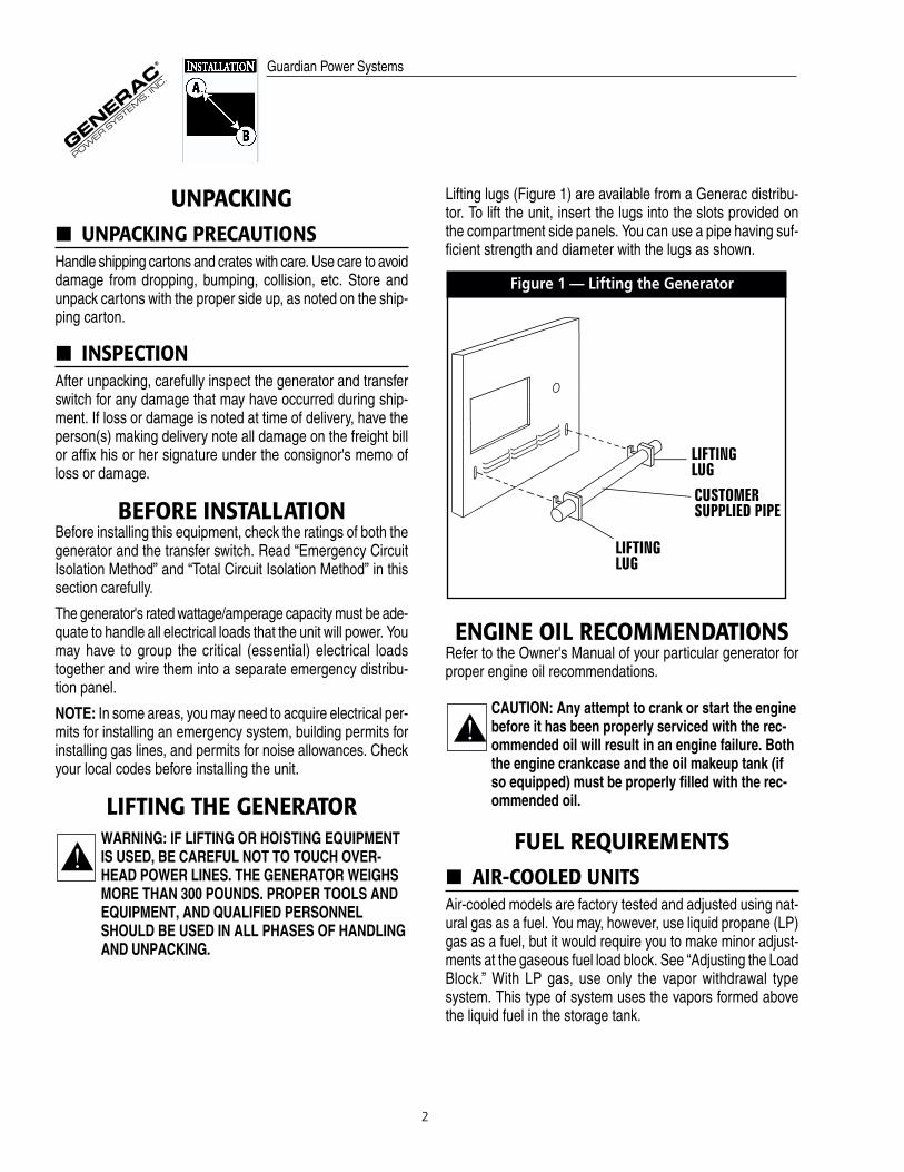
LIFTING THE GENERATORWARNING: IF LIFTING OR HOISTING EQUIPMENTIS USED, BE CAREFUL NOT TO TOUCH OVER-HEAD POWER LINES. THE GENERATOR WEIGHSMORE THAN 300 POUNDS. PROPER TOOLS ANDEQUIPMENT, AND QUALIFIED PERSONNELSHOULD BE USED IN ALL PHASES OF HANDLINGAND UNPACKING.
Lifting lugs (Figure 1) are available from a Generac distribu-tor. To lift the unit, insert the lugs into the slots provided onthe compartment side panels. You can use a pipe having suf-ficient strength and diameter with the lugs as shown.
Figure 1 — Lifting the Generator
ENGINE OIL RECOMMENDATIONSRefer to the Owner's Manual of your particular generator forproper engine oil recommendations.
CAUTION: Any attempt to crank or start the enginebefore it has been properly serviced with the rec-ommended oil will result in an engine failure. Boththe engine crankcase and the oil makeup tank (ifso equipped) must be properly filled with the rec-ommended oil.
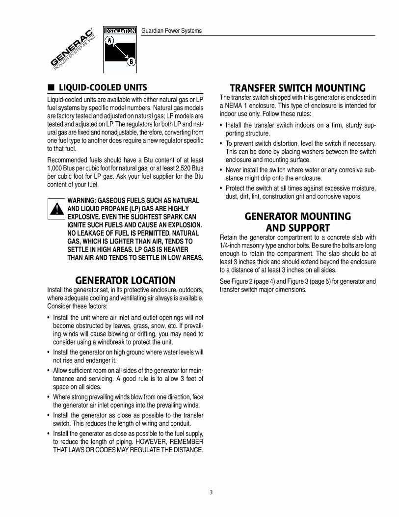
FUEL REQUIREMENTSAIR-COOLED UNITS
Air-cooled models are factory tested and adjusted using nat-ural gas as a fuel. You may, however, use liquid propane (LP)gas as a fuel, but it would require you to make minor adjust-ments at the gaseous fuel load block. See “Adjusting the LoadBlock.” With LP gas, use only the vapor withdrawal typesystem. This type of system uses the vapors formed abovethe liquid fuel in the storage tank.
Guardian Power Systems
3
LIQUID-COOLED UNITSLiquid-cooled units are available with either natural gas or LPfuel systems by specific model numbers. Natural gas modelsare factory tested and adjusted on natural gas; LP models aretested and adjusted on LP. The regulators for both LP and nat-ural gas are fixed and nonadjustable, therefore, converting fromone fuel type to another does require a new regulator specificto that fuel.
Recommended fuels should have a Btu content of at least1,000 Btus per cubic foot for natural gas, or at least 2,520 Btusper cubic foot for LP gas. Ask your fuel supplier for the Btucontent of your fuel.
WARNING: GASEOUS FUELS SUCH AS NATURALAND LIQUID PROPANE (LP) GAS ARE HIGHLYEXPLOSIVE. EVEN THE SLIGHTEST SPARK CANIGNITE SUCH FUELS AND CAUSE AN EXPLOSION.NO LEAKAGE OF FUEL IS PERMITTED. NATURALGAS, WHICH IS LIGHTER THAN AIR, TENDS TOSETTLE IN HIGH AREAS. LP GAS IS HEAVIERTHAN AIR AND TENDS TO SETTLE IN LOW AREAS.
GENERATOR LOCATIONInstall the generator set, in its protective enclosure, outdoors,where adequate cooling and ventilating air always is available.Consider these factors:
• Install the unit where air inlet and outlet openings will notbecome obstructed by leaves, grass, snow, etc. If prevail-ing winds will cause blowing or drifting, you may need toconsider using a windbreak to protect the unit.
• Install the generator on high ground where water levels willnot rise and endanger it.
• Allow sufficient room on all sides of the generator for main-tenance and servicing. A good rule is to allow 3 feet ofspace on all sides.
• Where strong prevailing winds blow from one direction, facethe generator air inlet openings into the prevailing winds.
• Install the generator as close as possible to the transferswitch. This reduces the length of wiring and conduit.
• Install the generator as close as possible to the fuel supply,to reduce the length of piping. HOWEVER, REMEMBERTHAT LAWS OR CODES MAY REGULATE THE DISTANCE.
TRANSFER SWITCH MOUNTINGThe transfer switch shipped with this generator is enclosed ina NEMA 1 enclosure. This type of enclosure is intended forindoor use only. Follow these rules:
• Install the transfer switch indoors on a firm, sturdy sup-porting structure.
• To prevent switch distortion, level the switch if necessary.This can be done by placing washers between the switchenclosure and mounting surface.
• Never install the switch where water or any corrosive sub-stance might drip onto the enclosure.
• Protect the switch at all times against excessive moisture,dust, dirt, lint, construction grit and corrosive vapors.
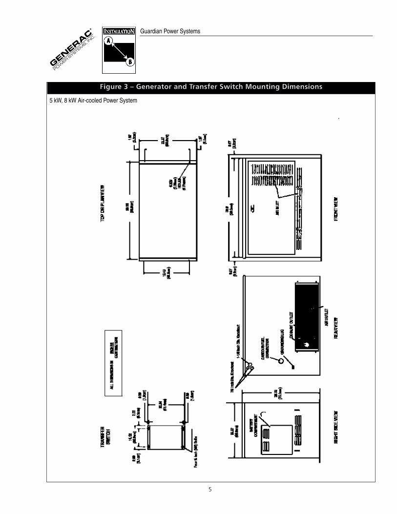
GENERATOR MOUNTINGAND SUPPORT
Retain the generator compartment to a concrete slab with 1/4-inch masonry type anchor bolts. Be sure the bolts are longenough to retain the compartment. The slab should be atleast 3 inches thick and should extend beyond the enclosureto a distance of at least 3 inches on all sides.
See Figure 2 (page 4) and Figure 3 (page 5) for generator andtransfer switch major dimensions.
Guardian Power Systems

4
FFiigguurree 22 –– GGeenneerraattoorr aanndd TTrraannssffeerr SSwwiittcchh MMoouunnttiinngg DDiimmeennssiioonnss
10 kW, 15 kW, 20 kW and 25 kW Liquid-cooled Power Systems
Guardian Power Systems1.
5 Li
ter G
as M
itizu
bish
i Eng
ine
Fuel
sys
tem
com
es s
et u
p fo
r out
side
fuel
stub
up
conn
ectio
ns.
Smal
l fue
l sys
tem
mod
ifica
tions
are
requ
ired
for i
nsid
e st
ub u
p co
nnec
tions
. Al
l dim
ensi
ons
are
in m
illim
eter
s.
5
5 kW, 8 kW Air-cooled Power System
FFiigguurree 33 –– GGeenneerraattoorr aanndd TTrraannssffeerr SSwwiittcchh MMoouunnttiinngg DDiimmeennssiioonnss
Guardian Power Systems
6
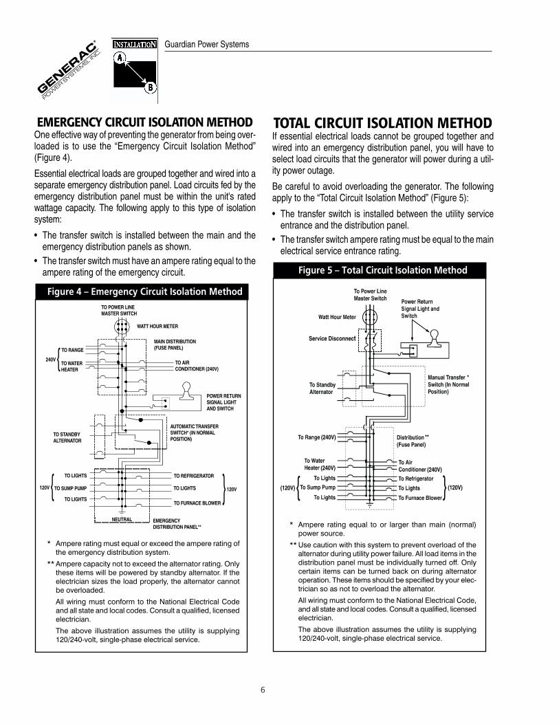
EMERGENCY CIRCUIT ISOLATION METHODOne effective way of preventing the generator from being over-loaded is to use the “Emergency Circuit Isolation Method”(Figure 4).
Essential electrical loads are grouped together and wired into aseparate emergency distribution panel. Load circuits fed by theemergency distribution panel must be within the unit's ratedwattage capacity. The following apply to this type of isolationsystem:
• The transfer switch is installed between the main and the emergency distribution panels as shown.
• The transfer switch must have an ampere rating equal to theampere rating of the emergency circuit.
Figure 4 – Emergency Circuit Isolation Method
TOTAL CIRCUIT ISOLATION METHODIf essential electrical loads cannot be grouped together andwired into an emergency distribution panel, you will have toselect load circuits that the generator will power during a util-ity power outage.
Be careful to avoid overloading the generator. The followingapply to the “Total Circuit Isolation Method” (Figure 5):
• The transfer switch is installed between the utility serviceentrance and the distribution panel.
• The transfer switch ampere rating must be equal to the mainelectrical service entrance rating.
Figure 5 – Total Circuit Isolation Method
Service Disconnect
Guardian Power Systems
* Ampere rating must equal or exceed the ampere rating ofthe emergency distribution system.
** Ampere capacity not to exceed the alternator rating. Onlythese items will be powered by standby alternator. If theelectrician sizes the load properly, the alternator cannotbe overloaded.
All wiring must conform to the National Electrical Code and all state and local codes. Consult a qualified, licensedelectrician.
The above illustration assumes the utility is supplying120/240-volt, single-phase electrical service.
* Ampere rating equal to or larger than main (normal)power source.
** Use caution with this system to prevent overload of thealternator during utility power failure. All load items in thedistribution panel must be individually turned off. Onlycertain items can be turned back on during alternatoroperation. These items should be specified by your elec-trician so as not to overload the alternator.
All wiring must conform to the National Electrical Code,and all state and local codes. Consult a qualified, licensedelectrician.
The above illustration assumes the utility is supplying120/240-volt, single-phase electrical service.

7
GASEOUS FUEL SYSTEMIMPORTANT: THE FOLLOWING INFORMATION PERTAIN-ING TO GASEOUS FUEL SYSTEMS IS PROVIDED TOASSIST GASEOUS FUEL TECHNICIANS IN PLANNINGINSTALLATIONS. IN NO WAY SHOULD THIS INFORMA-TION BE INTERPRETED TO CONFLICT WITH APPLICABLEFUEL GAS CODES. CONSULT WITH YOUR LOCAL FUELSUPPLIER OR FIRE MARSHALL IF QUESTIONS OR PROBLEMS ARISE.
Consider the following factors when planning to install the fuelsupply system:
• Install a flexible length of line between the generator fuelconnection and rigid piping. The flexible hose must beapproved for use with gaseous fuels.
• Gas pressure at the generator's gaseous fuel connectionshould be a minimum of 11 inches of water and should notexceed 14 inches of water (1/2 psi).
• If you use liquid petroleum (LP) gas as fuel, use only a vaporwithdrawal type system.
FUEL CONSUMPTIONSee Figure 6 for fuel supply requirements. Ratings are at 100percent load.
Figure 6 – Fuel Consumption Table
NG FT³/HR LP FT³/HR
5 kW 115 45
8 kW 165 65
10 kW 200 78
15 kW 277 110
20 kW 360 143
25 kW 441 175
FUEL PIPE SIZINGSee Figure 7 for proper sizing of fuel supply piping. Insuffi-cient fuel pipe size can cause hard starting, poor engine performance and inability to carry load.
Figure 7 – Fuel Systems NG and LP Vapor Pipe Sizing
Length of Pipe Iron Pipe Size (IPS Inches)½" ¾" 1" 1 ¼" 1 ½" 2"
15' 76 172 345 750 1220 2480 30' 52 120 241 535 850 1780 45' 43 99 199 435 700 1475 60' 38 86 173 380 610 1290 75' 77 155 345 545 1120 90' 70 141 310 490 1000
105 65 131 285 450 920 120 120 270 420 860 150 109 242 380 780 180 100 225 350 720 210 92 205 320 660 240 190 300 620 270 178 285 580 300 170 270 545 450 140 226 450 600 119 192 390
GENERATOR AC CONNECTIONSYSTEM
The generator AC power winding is a dual winding type (Figure8), which provides a three-wire AC connection system. Eachsingle-stator AC power winding can supply 120 volts AC. Con-necting the two windings in series results in a 240-volt ACoutput. Stator AC output leads 11 and 44 are the two “hot”leads; the junction of leads 22 and 33 form the neutral lead.
Figure 8 – Generator AC Connection System.
Guardian Power Systems

8
WIRING INTERCONNECTIONSCAUTION: This generator uses an UNGROUNDEDneutral line consisting of junction of stator leads 22and 33. Figure 9 and Figure 10 are interconnectiondiagrams of home standby electrical systems.Power voltage leads and transfer switch “signal”leads must be run in separate conduit.
All wiring must be the proper size, properly supported, ofapproved insulative qualities, and protected by approved con-duit. Use a length of flexible conduit between the generatorand any rigid conduit.
NOTE: See also “Emergency Circuit Isolation Method” and“Total Circuit Isolation Method” on page 6.
Complete the following AC power lead connections for single-phase units (Figure 9):
1. Connect utility power supply leads to transfer switch termi-nals N1, N2 and switch's neutral lug.
2. Connect generator AC output leads from generator main cir-cuit breaker (CB1) and the generator neutral lug to transferswitch terminals E1, E2 and the switch's neutral lug.
3. Connect circuit load leads to customer load and to transferswitch terminals T1, T2 and neutral.
Complete the following AC power lead connections for three-phase units (Figure 10):
1. Connect utility power supply leads to transfer switch termi-nals N1, N2, N3 and switch's neutral lug.
2. Connect generator AC output leads from generator main cir-cuit breaker (CB1) and the generator neutral lug to transferswitch terminals E1, E2 , E3 and the switch's neutral lug.
3. Connect circuit load leads to customer load and to transferswitch terminals T1, T2, T3 and neutral.
N1 N3N2
T3T1 T2
E3E1 E2
UTILITY SUPPLY
CUSTOMER LOAD
NEUTRALLUGTRANSFER
SWITCH
LO
AD
1
LO
AD
2
UT
ILIT
Y1
UT
ILIT
Y2
AC GENERATORCONTROL PANEL
NEUTRALCONNECTION
CB2
00
UTILITY 1UTILITY2LOAD1LOAD2
23194
23
194
E1
E2
E3
N3, E3 ANDT3 NOT USED
ON SINGLE PHASE SYSTEMS
NOTE: POWER LEADS AND TRANSFER
SWITCH LEADS MUST BE RUN IN TWO
SEPARATE CONDUITS
FFiigguurree 1100 –– IInntteerrccoonnnneeccttiioonn DDiiaaggrraamm ffoorr TThhrreeee--pphhaassee PPoowweerr SSyysstteemm ((110000//220000AA YY--ttyyppee))
Guardian Power Systems
FFiigguurree 99 –– IInntteerrccoonnnneeccttiioonn DDiiaaggrraamm ffoorr SSiinnggllee--pphhaassee PPoowweerr SSyysstteemm ((110000AA,, VV--ttyyppee))

9
PREPACKAGED GENERATORS ANDGTS TRANSFER SWITCHES
Guardian generators with a liquid-cooled engine may beinstalled with either a prepackaged transfer switch or with astandard GTS-type automatic transfer switch (Figure 11). Youcan do this by connecting generator control console terminals178 and 183 to identically numbered terminals in the GTSswitch. Also, you must connect utility source power to gener-ator terminals Utility 1 and Utility 2 and Load 1 and Load 2.Wires 23 and 194 are not connected.
When a prepackaged generator is installed with a standardGTS-type switch, solid-state circuit boards in the transferswitch control automatic operation. For automatic operatingsequences, parameters and timing, refer to the appropriateGTS transfer switch manual.
Automatic operation for prepackaged generators installed withprepackaged transfer switches is controlled by a control modulecircuit board in the control panel. Refer to the “OPERATION”section of this manual.
CONTROL CIRCUIT INTERCONNECTIONS
These interconnections consist of “Utility” and “Load” leads,plus leads 23 and 194. These six leads must be routed in con-duit that is separate from the generator AC power leads.Control lead functions may be briefly described as follows:
1. Utility 1 and Utility 2 (air-cooled); or N1A and N2 (liquid-cooled): Deliver utility source power to the generator's logiccircuit board.
2. Load 1 and Load 2 (air-cooled); or T1 and T2 (liquid-cooled):Used to operate seven-day exerciser circuit on the gener-ator's logic circuit board.
3. Leads 23 and 194 (both types): After the generator starts,the logic circuit board in control panel delivers a “transfer”signal via these two leads. • When logic circuit board action closes this circuit, it
causes transfer switch main contacts to actuate and con-nect load circuits to generator output.
• When utility source voltage is restored, logic board opensleads 23 and 194 circuit. Loads are then transferredback to utility circuit.
NOTE: Recommended size of control circuit leads (Utility 1and 2, Load 1 and 2, 23 and 194) is No. 14 AWG strandedcopper wire.
ADAPTING THREE-PHASE TRANSFER SWITCH
The generator you are installing may include a prepackagedtransfer switch configured for three-phase loads. If you wantto adapt this kind of transfer switch for single-phase loads, proceed as follows:
1. Discard the three-phase power monitor (PM) found insidethe enclosure. You will not use it with a single-phase system.
2. Locate the eight-pin octal relay socket in the lower leftcorner of the transfer switch enclosure.
3. Move Wire N1A from Terminal 8 to Terminal 1 by cutting thelug off of N1A , stripping wire 5/16" from end, and insertingthe wire under screw of Terminal 1.
NOTE: Moving N1A from Terminal 8 to Terminal 1 takes thethree-phase voltage monitor out of the sensing circuit. Now,the control circuit board in the control module assembly (CMA)senses utility voltage.
4. Now, connect the control wires as follows:• Connect Utility Supply to lugs N1 and N2.• Connect the Customer Load lugs T1 and T2.• Connect the Standby Supply to lugs E1 and E2.
N1
T2T1
E2E1
N2
UTILITY SUPPLY
CUSTOMER LOAD
NEUTRALLUGTRANSFER
SWITCH
17
81
83
LO
AD
1
LO
AD
2
UT
ILIT
Y1
UT
ILIT
Y2
AC GENERATORCONNECTOR PANEL
NEUTRALCONNECTION
11
44
178183
C81
22
33
UTILITY 1
UTILITY 2
LOAD 1
LOAD 2
FFiigguurree 1111 –– IInntteerrccoonnnneeccttiioonn wwiitthh GGTTSS TTrraannssffeerr SSwwiittcchh ((110000AA,, YY--ttyyppee))
Guardian Power Systems

10
OPTIONAL REMOTE ALARM RELAYTerminal 229 on the control module assembly (CMA) for liquid-cooled home standby generators provides a convenientconnection for an optional remote alarm relay. This connec-tion does not have ample current capacity for direct connectionof alarm devices. The connected alarm relay must not exceedabout 100 milliamps current flow.
Notice in Figure 12 that the connected remote alarm devicemust have its own power supply, connected across the optionalrelay contacts. To operate the alarm relay, wire 15 is routedto terminal 15 of terminal board TB1, then to the alarm relaycoil, back to terminal 229. The alarm relay is then energizedby control logic circuit board action when an engine faultoccurs. Remember, the current flow required to operate thealarm relay must not exceed 100 milliamps.
GROUNDING THE GENERATORGenerally, connecting a No. 12 AWG stranded copper wire tothe grounding lug (Figure 13) and to an earth-driven copperor brass grounding rod (electrode) will adequately ground thegenerator. However, local codes may vary widely. Consult witha local electrician for grounding requirements in your area.
Figure 13 – Grounding the Generator
FFiigguurree 1122 –– OOppttiioonnaall AAllaarrmm RReellaayy IInntteerrccoonnnneeccttiioonnss
Guardian Power Systems

11
BATTERY INSTALLATIONRefer to the Owner's Manual for the recommended battery foryour home standby generator. Fill the battery with the properelectrolyte fluid and have the battery fully charged beforeinstalling it.
Before installing and connecting the battery, complete the following steps:
1. Set the generator's Manual/Off/Auto switch to OFF.
2. Turn off utility power supply to the transfer switch.
WARNING: IF THE MANUAL/OFF/AUTO SWITCH ISNOT SET TO ITS “OFF” POSITION, THE GENERA-TOR CAN CRANK AND START AS SOON ASBATTERY CABLES ARE CONNECTED. IF UTILITYPOWER SUPPLY IS NOT TURNED OFF, SPARKINGCAN OCCUR AT BATTERY POSTS AND CAUSE ANEXPLOSION.
Battery cables were factory connected at the generator (Figure14). Connect cables to battery posts as follows:
1. Connect the red battery cable (from starter contactor) to thebattery post indicated by a positive, POS or (+).
2. Connect the black battery cable (from frame ground) to thebattery post indicated by a negative, NEG or (—).
Figure 14 – Battery Cable Connections
NOTE: With the battery installed and utility power source volt-age available to the transfer switch, the battery receives a tricklecharge while the engine is not running, to prevent self-discharge. The trickle charge feature cannot be used torecharge a discharged battery.
POST INSTALLATION INSPECTIONBefore placing the home standby electrical system into service, inspect the entire installation carefully. Some areasmay require that an inspection be performed by a building orelectrical inspector.
FFiigguurree 1155 –– TTyyppiiccaall EEmmeerrggeennccyy PPoowweerr SSyysstteemm
Guardian Power Systems
12
Guardian Power SystemsPost
Installation
Start-up
Tests
The air-cooled generator set was factory tested and adjustedusing natural gas as fuel. The liquid-cooled generator set wasfactory tested and adjusted using natural gas or liquid propane(LP) gas according to specifications. You should not be requiredto adjust the unit any further except under special circum-stances.
WARNING: DO NOT MAKE ANY UNNECESSARYADJUSTMENTS. FACTORY SETTINGS ARE COR-RECT FOR MOST APPLICATIONS. HOWEVER,WHEN MAKING ADJUSTMENTS, BE CAREFUL TOAVOID OVERSPEEDING THE ENGINE.
CHECK TRANSFER SWITCH OPERATION
Refer to your Home Standby Generator Owner's Manual formanual operation procedures.
WARNING: DO NOT ATTEMPT MANUAL TRANS-FER SWITCH OPERATION UNTIL ALL POWERVOLTAGE SUPPLIES TO THE TRANSFER SWITCHHAVE BEEN POSITIVELY TURNED OFF. FAILURETO TURN OFF ALL POWER VOLTAGE SUPPLIESWILL RESULT IN EXTREMELY HAZARDOUS ANDPOSSIBLY FATAL ELECTRICAL SHOCK.
ELECTRICAL CHECKSComplete electrical checks as follows:
1. Turn on the utility power supply to the transfer switch, usingthe means provided (such as a utility main line circuitbreaker).
DANGER: THE TRANSFER SWITCH IS NOW ELEC-TRICALLY “HOT.” CONTACT WITH “HOT” PARTSWILL RESULT IN EXTREMELY HAZARDOUS ANDPOSSIBLY FATAL ELECTRICAL SHOCK. PROCEEDWITH CAUTION.
2. Use an accurate AC voltmeter to check utility power sourcevoltage across terminals N1 and N2. Nominal line-to-line volt-age should be 240 volts AC.
3. Check utility power source voltage across terminals N1 andthe transfer switch neutral lug; then across terminal N2 andneutral. Nominal line-to-neutral voltage should be 120 volts AC.
4. When certain that utility supply voltage is compatible withtransfer switch and load circuit ratings, turn OFF the utilitypower supply to the transfer switch.
5. Set the generator's main circuit breaker to its OFF (or open)position. Initial tests will be conducted at no-load condition.
6. On the generator panel, set the Manual/Off/Auto switch toMANUAL. The engine should crank and start.
7. Let the engine warm up for about five minutes to allow inter-nal temperatures to stabilize. Then, set the generator’s maincircuit breaker to its ON (or closed) position.
DANGER: PROCEED WITH CAUTION. GENERATORPOWER VOLTAGE IS NOW SUPPLIED TO THETRANSFER SWITCH. CONTACT WITH LIVE TRANS-FER SWITCH PARTS WILL RESULT IN DANGEROUSAND POSSIBLY FATAL ELECTRICAL SHOCK.
8. Connect an accurate AC voltmeter and an AC frequencymeter across transfer switch terminal lugs E1 and E2. Volt-age should be 242-252 volts; frequency should read about61-63 Hertz.
9. Connect the AC voltmeter test leads across terminal lug E1and neutral; then across E2 and neutral. In both cases,voltage reading should be 121-126 volts AC.
10.Set the generator’s main circuit breaker to its OFF (oropen) position. Let the engine run at no-load for a few min-utes to stabilize internal engine generator temperatures.
11.Set the generator's Manual/Off/Auto switch to OFF. Theengine should shut down.
IMPORTANT: DO NOT PROCEED UNTIL YOU ARE CERTAINTHAT GENERATOR AC VOLTAGE AND FREQUENCY ARECORRECT AND WITHIN THE STATED LIMITS. GENER-ALLY, IF BOTH AC FREQUENCY AND VOLTAGE ARE HIGHOR LOW, THE ENGINE GOVERNOR REQUIRES ADJUST-MENT. IF FREQUENCY IS CORRECT, BUT VOLTAGE ISHIGH OR LOW, THE GENERATOR'S VOLTAGE REGULATORREQUIRES ADJUSTMENT.
13
BEFORE INITIAL START-UPBefore starting, complete the following:
1. Set the generator's Manual/Off/Auto switch to the OFF position.
2. Turn OFF the utility power supply to the transfer switchusing the means provided (such as the utility main line cir-cuit breaker).
3. Check the engine crankcase oil level and, if necessary, fillto the dipstick FULL mark with the recommended oil. Do notoverfill above the FULL mark.
4. Check the fuel supply. Gaseous fuel lines must have beenproperly purged and leak tested in accordance with applic-able fuel-gas codes. All fuel shutoff valves in the fuel supplylines must be open.
GENERATOR TESTS UNDER LOADTo test the generator set with electrical loads applied, proceedas follows:
1.Set generator’s main circuit breaker to its OFF (or open)position.
2.Set the generator's Manual/Off/Auto switch to OFF.3.Turn OFF the utility power supply to the transfer switch,
using the means provided (such as a utility main line circuit breaker).
WARNING: DO NOT ATTEMPT MANUAL TRANS-FER SWITCH OPERATION UNTIL ALL POWERVOLTAGE SUPPLIES TO THE TRANSFER SWITCHHAVE BEEN POSITIVELY TURNED OFF. FAILURETO TURN OFF ALL POWER VOLTAGE SUPPLIESWILL RESULT IN EXTREMELY HAZARDOUS ANDPOSSIBLY FATAL ELECTRICAL SHOCK.
4.Manually set the transfer switch to the STANDBY position,i.e., load terminals connected to the generator's E1/E2 ter-minals. The transfer switch operating lever should bedown.
5.Set the generator's Manual/Off/Auto switch to MANUAL.The engine should crank and start immediately.
6.Let the engine stabilize and warm up for a few minutes.7.Set the generator’s main circuit breaker to its ON (or closed)
position. Loads are now powered by the standby generator.8.Turn ON electrical loads. Apply an electrical load equal to
the full rated wattage/amperage capacity of the installedgenerator.
9.Connect an accurate AC frequency meter across terminallugs E1 and E2. Voltage should be greater than 230 volts;frequency should be greater than 58 Hertz.
10.Let the generator run at full rated load for 20-30 minutes.Listen for unusual noises, vibration or other indications ofabnormal operation. Check for oil leaks, evidence of over-heating, etc.
11.When testing under load is complete, turn OFF electricalloads.
12.Set the generator's main circuit breakers to their OFF (oropen) positions.
13.Let the engine run at no-load for a few minutes.14.Set the Manual/Off/Auto switch to OFF. The engine should
shut down.
CHECKING AUTOMATIC OPERATIONTo check the system for proper automatic operation, proceedas follows:
1.Check that the Manual/Off/Auto switch is set to OFF.
2.Manually set the transfer switch to the UTILITY position, i.e.,load terminals connected to the utility power source side.
3.Turn ON the utility power supply to the transfer switch, usingthe means provided (such as a utility main line circuitbreaker).
4.Set the Manua/Off/Auto switch to AUTO. The system is nowready for automatic operation.
5.Turn OFF the utility power supply to the transfer switch.
With the Manual/Off/Auto switch at AUTO, the engine shouldcrank and start when the utility source power is turned OFF.After starting, the transfer switch should connect load circuitsto the standby side. Let the system go through its entire auto-matic sequence of operation.
With the generator running and loads powered by generatorAC output, turn ON the utility power supply to the transferswitch. The following should occur:
• After about six seconds, the switch should transfer loads backto the utility power source.
• About one minute after retransfer, the engine should shutdown.
Guardian Power SystemsPost
Installation
Start-up
Tests

14
GASEOUS FUEL LOAD BLOCK ADJUSTMENT
If you are installing an air-cooled home standby generator,you may need to adjust gaseous fuel load block.
RECONFIGURING THE FUEL SYSTEMTo reconfigure the fuel system, follow these steps:
• Remove the carburetor fuel hose from the natural gas portof the fuel load block and the brass fitting (Figure 16).
Figure 16 – Natural Gas Setup
• Remove the blanking plug from the LP port of the loadblock (Figure 16).
• Refit the hose and fitting to the LP port and the blanking plugto the natural gas port (Figure 17).
Figure 17 – LP Gas Setup
ADJUSTING THE LOAD BLOCKWhen the natural has system is being used, the load block is fitted with an adjustment screw that has been calibrated toprovide maximum power. However, because of variations inthe Btu content of natural gas across the country, it may benecessary to readjust the load block.
• Connect a frequency meter to the output of the generator.• Start the unit and apply full load (33 amps at 240 volts – 66
amps at 120 volts AC).• Allow the unit to stabilize; then, turn the adjustment
screw slowly clockwise or counterclockwise and watch thefrequency.
• When the highest frequency is reached, turn the adjustmentscrew counterclockwise 1/4 turn.
• The fuel system is now set.• For LP gas operations, the hose and blanking plug must be
reconfigured as shown in Figure 17. The unit is set to pro-vide maximum power using LP gas..
ENGINE GOVERNOR ADJUSTMENTIf both AC frequency and voltage are correspondingly high orlow, adjust the engine governor as follows:
5 KW UNITS1. Loosen the GOVERNOR CLAMP BOLT (Figure 18).
2. Push the spring end of the GOVERNOR LEVER clockwiseto the wide open throttle position of the lever.
• Hold the GOVERNOR LEVER at wide open throttle and,with a pair of pliers, rotate the GOVERNOR SHAFT fullyclockwise.
• While holding the GOVERNOR SHAFT fully clockwise andthe GOVERNOR LEVER at wide open throttle, tighten theGOVERNOR CLAMP BOLT to 70 inch-pounds (8 N-m).
3. Start the engine; let it stabilize and warm up at no-load.
4. Turn the ADJUSTER NUT to obtain a frequency reading of62 Hertz.
5. Determine if the GOVERNOR SPRING is properly locatedin the slot of the GOVERNOR LEVER as follows:
• If droop is excessive, move the GOVERNOR SPRINGdown one slot on the LEVER.
Guardian Power SystemsPost
Installation
Start-up
Tests
15
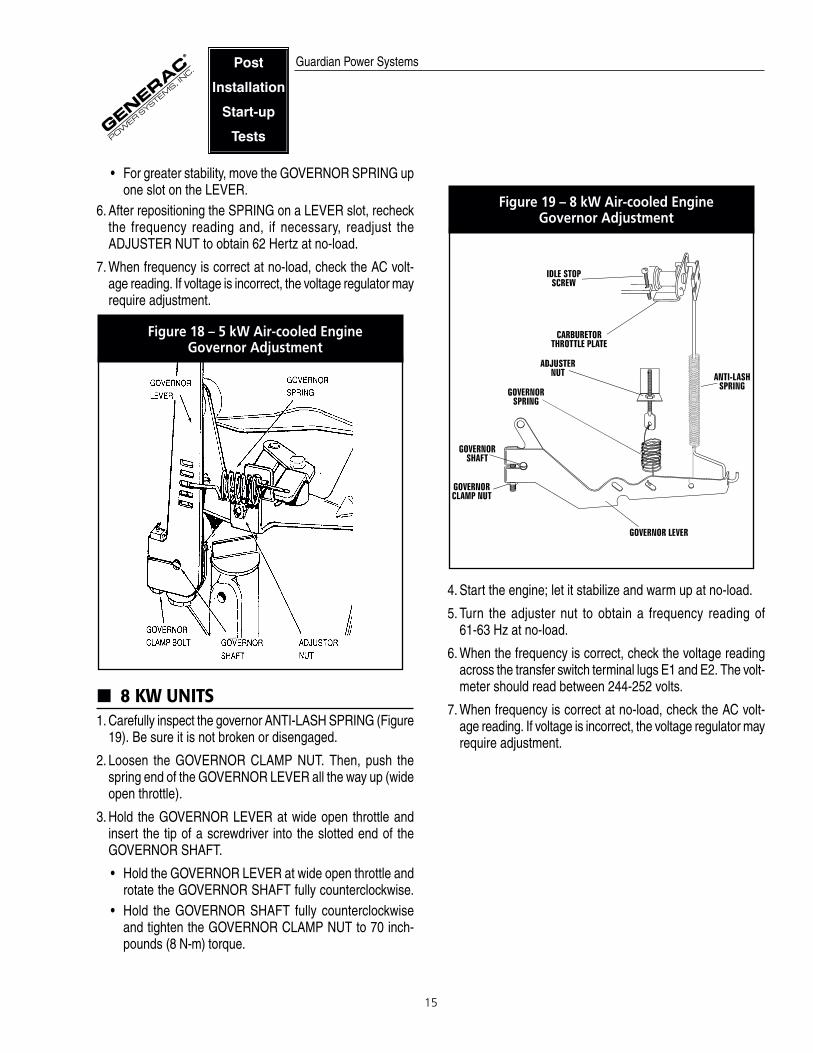
• For greater stability, move the GOVERNOR SPRING upone slot on the LEVER.
6. After repositioning the SPRING on a LEVER slot, recheckthe frequency reading and, if necessary, readjust theADJUSTER NUT to obtain 62 Hertz at no-load.
7. When frequency is correct at no-load, check the AC volt-age reading. If voltage is incorrect, the voltage regulator mayrequire adjustment.
Figure 18 – 5 kW Air-cooled Engine Governor Adjustment
8 KW UNITS1. Carefully inspect the governor ANTI-LASH SPRING (Figure
19). Be sure it is not broken or disengaged.
2. Loosen the GOVERNOR CLAMP NUT. Then, push thespring end of the GOVERNOR LEVER all the way up (wideopen throttle).
3. Hold the GOVERNOR LEVER at wide open throttle andinsert the tip of a screwdriver into the slotted end of the GOVERNOR SHAFT.
• Hold the GOVERNOR LEVER at wide open throttle androtate the GOVERNOR SHAFT fully counterclockwise.
• Hold the GOVERNOR SHAFT fully counterclockwiseand tighten the GOVERNOR CLAMP NUT to 70 inch-pounds (8 N-m) torque.
Figure 19 – 8 kW Air-cooled Engine Governor Adjustment
4. Start the engine; let it stabilize and warm up at no-load.
5. Turn the adjuster nut to obtain a frequency reading of 61-63 Hz at no-load.
6. When the frequency is correct, check the voltage readingacross the transfer switch terminal lugs E1 and E2. The volt-meter should read between 244-252 volts.
7. When frequency is correct at no-load, check the AC volt-age reading. If voltage is incorrect, the voltage regulator mayrequire adjustment.
Guardian Power SystemsPost
Installation
Start-up
Tests

16
ELECTRONIC GOVERNOR ADJUSTMENTThe electronic governor for liquid-cooled emergency power sys-tems is a stepper motor system. The system consists of agovernor module mounted inside the generator control panel,a stepper motor mounted near the injection pump or carbu-retor, and interconnecting wires and connection boxes (Figure20). You may be required to adjust the electronic governor whenyou install the system or when you replace the governor.
SETUP AND ADJUSTMENT PROCEDUREDetermine which direction the stepper motor must rotate toopen the throttle to “full fuel.” Adjust the rod length so the step-per motor is at its full rotation when the throttle is wide open.Then, tighten the jam nuts. Be sure the linkage moves freelyand does not bind in any way.
CONTROL MODULEPOTENTIOMETERS AND SWITCHES
The following is a description of the adjustment for the newelectronic governor control module and stepper motor:
Potentiometer (pot) Settings on Control Manual
Set GAIN, DROOP and STABILITY pots to midpoint.
Switch Settings
• Set the frequency switch to either 50 Hz (ON) or 60 Hz (OFF).
Set Direction SwitchDetermine which direction the stepper motor lever needs tobe set to open the throttle. Some units are set to open at theclockwise position, and some are set to open at the counter-clockwise position.
If the lever is set to open at the counterclockwise position, thenthe direction switch should be set in the “OFF” position. If thelever is set to open at the clockwise position, the directionshould be set to the “ON” position.
When the switches and pots are set correctly, start the engine.Adjust the gain pot if necessary to stabilize engine speed.
• Apply load to the system – 25-50 percent is best. If thesystem is unstable, reduce gain until it stabilizes.
• Adjust droop pot so that the engine speed recovers to thepreselected speed (50 or 60 Hz based on unit).
• Observe performance of the system when loads are appliedand removed.
• Increasing stability will decrease recovery time, but mayresult in damped oscillations (decreasing hertz aroundpreset speed). Decreasing stability will soften the recoveryand reduce the transient hertz.
Frequency and direction switches are integrated only at enginestart. Changing switch settings while the engine is running willhave no effect until the engine is stopped and restarted.
12V. DC
GROUND
HZ METER
REDBLACK
BLUE
FREQUENCY
DIRECTION
YELLOW
BROWNGAIN
STABILITY
DROOP
ORANGE
BLACK
STEPPER MOTOR PART #98290LOCATED NEAR CARBURETORINJECTION PUMP
TURN COUNTERCLOCKWISETO OPEN THROTTLE SETDIRCTION SWITCH TO "OFF"
TURN CLOCKWISE TOOPEN THROTTLE SETDIRECTION SWITCH TO "ON"
CONTROL MODULE PART #98647LOCATED IN CONTROL PANEL
FFiigguurree 2200 –– SStteeppppeerr MMoottoorr aanndd CCoonnttrrooll MMoodduullee
Guardian Power SystemsPost
Installation
Start-up
Tests

17
VOLTAGE REGULATOR ADJUSTMENTWith the frequency between 61-62 Hz, slowly turn the slottedpotentiometer (Figure 21) until line voltage reads 244-252volts.
Figure 21 – Voltage Adjustment Potentiometer
NOTE: The voltage regulator is housed in the generator'scontrol panel. The regulator maintains a voltage in direct pro-portion to frequency at a 2-to-1 ratio. For example, at 62 Hz,line-to-neutral voltage will be 124 volts.
THREE-PHASE MODELS1. Connect an accurate AC voltmeter and AC frequency meter
to the generator’s AC output leads.
2. On the regulator, set the potentiometers as follows (Figure 22):
A.Turn the “Voltage Adjust” pot fully counterclockwise.B.Set “Gain” to its centered (mid) position.C.Set “Stability” to its centered (mid) position.D.Do NOT adjust “Under-frequency Adjust.”
3. On the generator console, set the voltage adjust pot to itscentered (mid) position.
4. Turn OFF all electrical loads. Start-up and initial adjust-ment will be done under a “no-load” condition.
5. Start the engine. Let it stabilize and warm up at no-load.
6. Check the reading on the frequency meter. If necessary,adjust the engine governor to obtain a frequency as closeas possible to 60 Hz at no-load.
7. With the unit running at correct no-load frequency, observethe lamps (LEDs) on the voltage regulator. All lamps shouldbe ON.
8. Turn the regulators “Voltage Adjust” pot to obtain a line-to-line voltage output of 208 or 240 VAC.
9. If the red “Regulator” lamp (LED) is flashing, turn the “Stability” pot either direction until the flashing stops.
10.Apply an electrical load and check engine speed recovery.
A.Adjust the “Under-frequency Adjust” pot fully counter-clockwise to unload the unit and reduce load while theengine recovers.
B.For flat regulation (no voltage decrease as frequencydrops), set the “Under-frequency Adjust” pot fully clockwise.
C.To obtain a constant voltage reduction as frequencydecreases, set the “Under-frequency Adjust” pot fullycounterclockwise. Set point for this adjustment is 62 Hz(counterclockwise) to 52 Hz (clockwise).
11.With the electrical load still applied, check the “Regulator”lamp for flashing. If the lamp is flashing, adjust the “Stability” pot until the flashing stops.
12.If a better response is needed, adjust the “Gain” pot clock-wise as needed. Then (if needed), correct for instability byadjusting the “Stability” pot.
13.Turn off electrical loads. Then, recheck the regulator lamps(LEDs) at no-load.
When all adjustments have been completed, let the engine runat no-load for a few minutes to stabilize internal engine-gen-erator temperatures. Then, shut the generator down.
Figure 22 – Voltage Regulator 67680 (Three-phase Models)
Guardian Power SystemsPost
Installation
Start-up
Tests
18
SET WEEKLY EXERCISE CYCLEThe generator will start and exercise once every seven days.During this weekly exercise, the unit runs for about 20 min-utes and shuts down. Transfer of loads to generator output doesnot occur during the exercise.
To select the day and time for exercising, proceed as follows:
1. Set the Manual/Off/Auto switch to OFF.
2. Set the generator’s main circuit breaker to its OFF (or open)position.
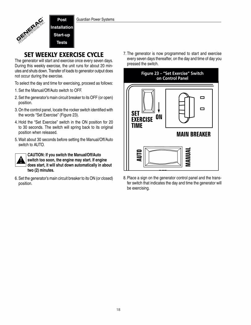
3. On the control panel, locate the rocker switch identified withthe words “Set Exercise” (Figure 23).
4. Hold the “Set Exercise” switch in the ON position for 20 to 30 seconds. The switch will spring back to its original position when released.
5. Wait about 30 seconds before setting the Manual/Off/Autoswitch to AUTO.
CAUTION: If you switch the Manual/Off/Auto switch too soon, the engine may start. If enginedoes start, it will shut down automatically in abouttwo (2) minutes.
6. Set the generator’s main circuit breaker to its ON (or closed)position.
7. The generator is now programmed to start and exerciseevery seven days thereafter, on the day and time of day youpressed the switch.
Figure 23 – “Set Exercise” Switch on Control Panel
8. Place a sign on the generator control panel and the trans-fer switch that indicates the day and time the generator willbe exercising.
Guardian Power SystemsPost
Installation
Start-up
Tests
19
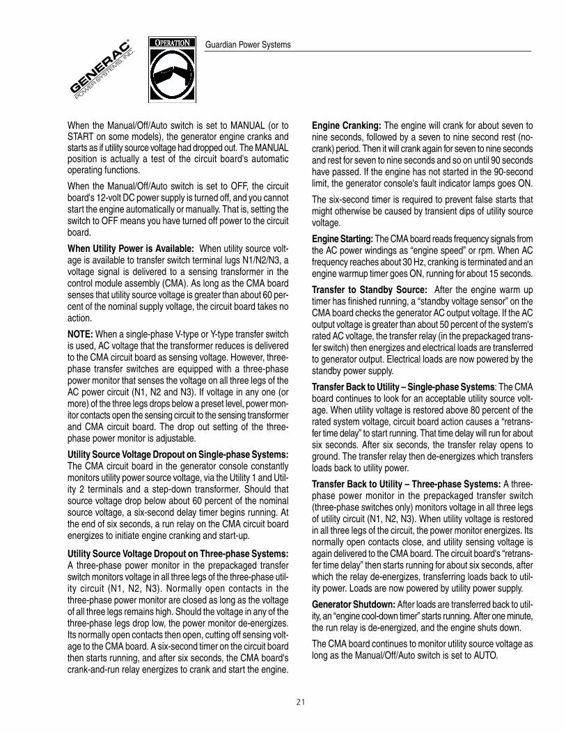
Air-cooled Control Panel
Liquid-cooled Control Panel
Guardian Power Systems
FUSE
15 AMP
USING THEMANUAL/OFF/AUTO SWITCH
“MANUAL” (OR “START”) POSITION (Figure 23)
• Set the switch to MANUAL (or START) to crank and startthe engine.
• Transfer to standby power will not occur after any manualstart unless utility is not available.
“AUTO” POSITION• This position provides fully automatic system operation.• Selecting this switch position allows the system to auto-
matically start and exercise the engine every seven days.
“OFF” POSITION• This position shuts down the engine.• This position prevents automatic operation.
Figure 24 – Generator Control Panels
WARNING: WITH SWITCH SET TO “AUTO,” THEENGINE MAY CRANK AND START AT ANY TIMEWITHOUT WARNING. SUCH AUTOMATIC START-ING NORMALLY OCCURS WHEN UTILITY POWERSOURCE VOLTAGE DROPS BELOW A PRESETLEVEL. TO PREVENT POSSIBLE INJURY THATMIGHT BE CAUSED BY SUCH SUDDEN STARTS,ALWAYS SET THE SWITCH TO “OFF” BEFOREWORKING ON OR AROUND THE GENERATOR ORTRANSFER SWITCH. THEN, PLACE A “DO NOTOPERATE” TAG ON THE GENERATOR PANEL ANDON THE TRANSFER SWITCH.
TO SELECT AUTOMATIC OPERATION1. Make sure the transfer switch main contacts are set to their
UTILITY position, i.e., load connected to utility power sourceside.
2. Be sure normal utility power source voltage is available totransfer switch terminal lugs N1 and N2.
3. Set the generator's Manual/Off/Auto switch to AUTO.
4. Set the generator’s main circuit breaker to its ON (or closed)position.
With the preceding steps completed, the generator will startautomatically when utility source voltage drops below a presetlevel. After the unit starts, loads are transferred to the standbypower source. Refer to “Sequence of Automatic Operation.”
MANUAL OPERATIONTo start the generator and set the transfer switch manually,refer to the Owner's Manual of your generator or the manualof your particular transfer switch.
DANGER: DO NOT ATTEMPT TO ACTIVATE THETRANSFER SWITCH MANUALLY UNTIL AFTERALL POWER VOLTAGE SUPPLIES TO THE SWITCHHAVE BEEN POSITIVELY TURNED OFF. FAILURETO TURN OFF ALL POWER VOLTAGE SUPPLIESMAY RESULT IN EXTREMELY HAZARDOUS ANDPOSSIBLY FATAL ELECTRICAL SHOCK.
TRANSFER BACK TO UTILITY POWER SOURCE
When utility power has been restored, you will want to trans-fer back to that source and shut down the generator. This canbe accomplished as follows:
20
1. Set the generator's main circuit breaker to its OFF (or open)position.
2. Let the engine run for a minute or two at no-load to stabi-lize the internal temperatures.
3. Set the generator's Manual/Off/Auto switch to OFF. Theengine should shut down.
4. Check that utility power supply to transfer switch is turnedOFF.
DANGER: DO NOT ATTEMPT TO ACTIVATE THETRANSFER SWITCH MANUALLY UNTIL AFTERALL POWER VOLTAGE SUPPLIES TO THE SWITCHHAVE BEEN POSITIVELY TURNED OFF. FAILURETO TURN OFF ALL POWER VOLTAGE SUPPLIESMAY RESULT IN EXTREMELY HAZARDOUS ANDPOSSIBLY FATAL ELECTRICAL SHOCK.
5. Manually set the transfer switch main contacts back toUTILITY position, i.e., loads connected to utility powersupply. Refer to the Owner's Manual of your generator fortransfer switch operation.
6. Turn ON the utility power supply to the transfer switch, usingthe means provided.
7. Set the system to automatic operation as outlined in “ToSelect Automatic Operation.”
SEQUENCE OF AUTOMATIC OPERATION
AIR-COOLED STANDBY SYSTEMSThe actual sequence of operation is controlled by sensors andtimers on control logic circuit board, as follows:
A.Utility Voltage Dropout Sensor• This sensor monitors utility source voltage.• If utility source voltage drops below about 60 percent of
the nominal supply voltage, the sensor energizes a six-second timer.
• If the utility source voltage drops below 60 percent of nom-inal supply for more than six seconds, the engine cranksand starts.
B.Engine Warm-up Time Delay• This mechanism lets the engine warm up for about 15
seconds before the load is transferred to a standbysource.
C.Standby Voltage Sensor • This sensor monitors generator AC output voltage. When
the voltage has reached 50 percent of the nominal ratedvoltage, transfer to standby can occur.
D.Utility Voltage Pickup Sensor • This sensor monitors utility power supply voltage. When
that voltage is restored above 80 percent of the nominalsource voltage, a retransfer time delay starts timing.
E.Retransfer Time Delay • This timer runs for about six seconds.• At end of a six-second delay, circuit board action de-ener-
gizes transfer relay in the transfer switch.• Retransfer to utility power source then occurs.
F. Engine Cool-down Timer• When the load is transferred back to utility power source,
the engine cool-down timer starts timing.• The timer will run for about one minute, and the gener-
ator will then shut down.Engine Starting:
The control module assembly (CMA) board reads frequencysignals from the stator battery charge windings and relatesthem to “engine speed” or rpm. When AC frequency reachesabout 30 Hz, cranking is terminated and an engine warmuptimer goes ON, running for about 15 seconds.
LIQUID-COOLED STANDBY SYSTEMSThe generator control panel houses a control logic circuitboard. This board constantly monitors utility power source volt-age. Should that voltage drop below a preset level, circuit boardaction will signal the engine to crank and start. After theengine starts, the circuit board signals the transfer switch toactivate and connect load circuits to the standby power supply(load terminal lugs T1/T2 connect to terminal lugs E1/E2).
When utility source voltage is restored above a preset level,generator circuit board action signals the transfer switch totransfer loads back to that power supply. After retransfer, theengine is signalled to shut down.
NOTE: Automatic operating sequences outlined in this sec-tion apply only to those home standby generators (Option “P”control panel) that have been installed along with a prepack-aged transfer switch. This is mentioned because you caninstall a GTS-type automatic transfer switch if you prefer. Thestandard GTS-type switch incorporates a solid-state “intelli-gence circuit” of its own. For more information, refer to theOwner's Manual of your GTS switch.
The Manual/Off/Auto Switch:
This switch on the generator control console must be set toAUTO for normal automatic operation.
Guardian Power Systems
21
When the Manual/Off/Auto switch is set to MANUAL (or toSTART on some models), the generator engine cranks andstarts as if utility source voltage had dropped out. The MANUALposition is actually a test of the circuit board's automatic operating functions.
When the Manual/Off/Auto switch is set to OFF, the circuitboard's 12-volt DC power supply is turned off, and you cannotstart the engine automatically or manually. That is, setting theswitch to OFF means you have turned off power to the circuitboard.
When Utility Power is Available: When utility source volt-age is available to transfer switch terminal lugs N1/N2/N3, avoltage signal is delivered to a sensing transformer in thecontrol module assembly (CMA). As long as the CMA boardsenses that utility source voltage is greater than about 60 per-cent of the nominal supply voltage, the circuit board takes noaction.
NOTE: When a single-phase V-type or Y-type transfer switchis used, AC voltage that the transformer reduces is deliveredto the CMA circuit board as sensing voltage. However, three-phase transfer switches are equipped with a three-phasepower monitor that senses the voltage on all three legs of theAC power circuit (N1, N2 and N3). If voltage in any one (ormore) of the three legs drops below a preset level, power mon-itor contacts open the sensing circuit to the sensing transformerand CMA circuit board. The drop out setting of the three-phase power monitor is adjustable.
Utility Source Voltage Dropout on Single-phase Systems:The CMA circuit board in the generator console constantlymonitors utility power source voltage, via the Utility 1 and Util-ity 2 terminals and a step-down transformer. Should thatsource voltage drop below about 60 percent of the nominalsource voltage, a six-second delay timer begins running. Atthe end of six seconds, a run relay on the CMA circuit boardenergizes to initiate engine cranking and start-up.
Utility Source Voltage Dropout on Three-phase Systems:A three-phase power monitor in the prepackaged transferswitch monitors voltage in all three legs of the three-phase util-ity circuit (N1, N2, N3). Normally open contacts in thethree-phase power monitor are closed as long as the voltageof all three legs remains high. Should the voltage in any of thethree-phase legs drop low, the power monitor de-energizes.Its normally open contacts then open, cutting off sensing volt-age to the CMA board. A six-second timer on the circuit boardthen starts running, and after six seconds, the CMA board'scrank-and-run relay energizes to crank and start the engine.
Engine Cranking: The engine will crank for about seven tonine seconds, followed by a seven to nine second rest (no-crank) period. Then it will crank again for seven to nine secondsand rest for seven to nine seconds and so on until 90 secondshave passed. If the engine has not started in the 90-secondlimit, the generator console's fault indicator lamps goes ON.
The six-second timer is required to prevent false starts thatmight otherwise be caused by transient dips of utility sourcevoltage.
Engine Starting: The CMA board reads frequency signals fromthe AC power windings as “engine speed” or rpm. When ACfrequency reaches about 30 Hz, cranking is terminated and anengine warmup timer goes ON, running for about 15 seconds.
Transfer to Standby Source: After the engine warm uptimer has finished running, a “standby voltage sensor” on theCMA board checks the generator AC output voltage. If the ACoutput voltage is greater than about 50 percent of the system'srated AC voltage, the transfer relay (in the prepackaged trans-fer switch) then energizes and electrical loads are transferredto generator output. Electrical loads are now powered by thestandby power supply.
Transfer Back to Utility – Single-phase Systems: The CMAboard continues to look for an acceptable utility source volt-age. When utility voltage is restored above 80 percent of therated system voltage, circuit board action causes a “retrans-fer time delay” to start running. That time delay will run for aboutsix seconds. After six seconds, the transfer relay opens toground. The transfer relay then de-energizes which transfersloads back to utility power.
Transfer Back to Utility – Three-phase Systems: A three-phase power monitor in the prepackaged transfer switch(three-phase switches only) monitors voltage in all three legsof utility circuit (N1, N2, N3). When utility voltage is restoredin all three legs of the circuit, the power monitor energizes. Itsnormally open contacts close, and utility sensing voltage isagain delivered to the CMA board. The circuit board's “retrans-fer time delay” then starts running for about six seconds, afterwhich the relay de-energizes, transferring loads back to util-ity power. Loads are now powered by utility power supply.
Generator Shutdown: After loads are transferred back to util-ity, an “engine cool-down timer” starts running. After one minute,the run relay is de-energized, and the engine shuts down.
The CMA board continues to monitor utility source voltage aslong as the Manual/Off/Auto switch is set to AUTO.
Guardian Power Systems

GENERAC® POWER SYSTEMS, INC.P.O. Box 8
Waukesha, WI 53187Phone: (414) 544-4811