Embed Size (px)
Citation preview

SUNNEN® PRODUCTS COMPANY • 7910 MANCHESTER ROAD • ST. LOUIS, MO 63143, U.S.A. • PHONE: 314-781-2100SUNNEN AG • Fabrikstrasse 1 • 8586 ENNETAACH • SWITZERLAND
READ THE FOLLOWING INSTRUCTIONS THOROUGHLY AND CAREFULLY BEFORE UNPACKING,INSPECTING, OR INSTALLING THE SUNNEN® TUBE HONING MACHINE.
I-HTB-100B
Installation, Setupand Operation
INSTRUCTIONS
for
SUNNEN® TUBE HONING MACHINEModel: HTB-S Series
“SUNNEN AND THE SUNNEN LOGO ARE REGISTERED TRADEMARKS OF SUNNEN PRODUCTS COMPANY.”
Version: V23File: HTB-SME_V23
Date: 17 October, 2006

GENERAL INFORMATION
The Sunnen® equipment has been designed and engineered for a wide variety of parts within the capacity and limitation of the equipment. With proper careand maintenance this equipment will give years of service.
READ THE FOLLOWING INSTRUCTIONS CAREFULLY AND THOROUGHLY BEFORE UNPACKING, INSPECTING, OR INSTALLING THIS EQUIPMENT.
IMPORTANT: Read any supplemental instructions BEFORE installing this equipment. These supplemental instructions give you important information toassist you with the planning and installation of your Sunnen equipment.
Sunnen Technical Service Department is available to provide telephone assistance for installation, programming, & troubleshooting of your Sunnenequipment. All support is available during normal business hours, 8:00 AM to 4:30 PM Central Time. Emergency breakdown support is available on a 24hour / 7 day basis.
Review all literature provided with your Sunnen equipment. This literature provides valuable information for proper installation, operation, and maintenanceof your equipment. Troubleshooting information can also be found within the Instructions. If you cannot find what you need, call for technical support.
Where applicable, programming information for your Sunnen equipment is also included. Most answers can be found in the literature packaged with yourequipment.
Help us help you. When ordering parts, requesting information, or technical assistance about your equipment, please have the followinginformation available:
• Have ALL MANUALS on hand. The Customer Services Representative or Technician will refer to it.• Have Model Number and Serial Number printed on your equipment Specification Nameplate.• Where Applicable: Have Drive model and all nameplate data. Motor type, brand, and all nameplate data.
For Troubleshooting, additional information may be required:• Power distribution information (type - delta, wye, power factor correction; other major switching devices used, voltage fluctuations)• Installation Wiring (separation of power & control wire; wire type/class used, distance between drive and motor, grounding).• Use of any optional devices/equipment between the Drive & motor (output chokes, etc.).
For fast service on your orders call:Sunnen Automotive Customer Service toll free at: 1-800-772-2878Sunnen Industrial Customer Service toll free at: 1-800-325-3670Customers outside the USA, contact your local authorized Sunnen Distributor.Additional information available at: http://www.sunnen.com or e-mail: [email protected]
NOTE: Sunnen reserves the right to change or revise specifications and product design in connection with any feature of our products contained herein.Such changes do not entitle the buyer to corresponding changes, improvements, additions, or replacements for equipment, supplies or accessoriespreviously sold. Information contained herein is considered to be accurate based on available information at the time of printing. Should any discrepancy ofinformation arise, Sunnen recommends that user verify the discrepancy with Sunnen before proceeding.
ESD PREVENTION REVIEW
Let's review the basics of a sound static control system and its effective implementation. First, in the three step plan:
1. Always ground yourself when handling sensitive components or assemblies.
2. Always use a conductive or shielded container during storage or transportation. These materials create a Faradaycage which will isolate the contents from static charges.
3. Open ESD safe containers only at a static safe work station.
At the static safe work station, follow these procedures before beginning any work:
A. Put on your wrist strap or foot grounding devices.
B. Check all grounding cords to make sure they are properly connected to ground, ensuring the effective dissipation of sta-tic charges.
C. Make sure that your work surface is clean and clear of unnecessary materials, particularly common plastics.
D. Anti-static bubble wrap has been included for use at the machine when an ESD safe workstation is not available.
You are now properly grounded and ready to begin work. Following these few simple rules and using a little common sense will go a longway toward helping you and your company in the battle against the hazards of static electricity. When you are working with ESD sen-sitive devices, make sure you:
GROUND
ISOLATE
NEUTRALIZE
ii

SUNNEN® LIMITED PRODUCT WARRANTY
Sunnen® Products Company and its subsidiaries (SPC) warrant that all new SPC honing machines, gaging equipment, tooling, and related equipment willbe free of defects in material and/or workmanship for a period of one year from the date of original shipment from SPC.
Upon prompt notification of a defect during the one-year period, SPC will repair, replace, or refund the purchase price, with respect to parts that prove to bedefective (as defined above). Any equipment or tooling which is found to be defective from improper use will be returned at the customer's cost or repaired(if possible) at customer's request. Customer shall be charged current rates for all such repair.
Prior to returning any SPC product, an authorization (RMA#) and shipping instructions must be obtained from the Customer Service Department or itemssent to SPC will be returned to the customer.
Warranty Limitations and Exclusions This Warranty does not apply to the following:
• Normal maintenance items subject to wear and tear: (belts, fuses, filters, etc).
• Damages resulting from but not limited to:› Shipment to the customer (for items delivered to customer or customer's agent F.O.B., Shipping Point)› Incorrect installation including improper lifting, dropping and/or placement› Incorrect electric power (beyond +/- 10% of rated voltage) including intermittent or random voltage spikes or drops› Incorrect air supply volume and/or pressure and/or contaminated air supply› Electromagnetic or radio frequency interference from surrounding equipment (EMI, RFI)› Storm, lightning, flood or fire damage› Failure to perform regular maintenance as outlined in SPC manuals› Improper machine setup or operation causing a crash to occur› Misapplication of the equipment› Use of non-SPC machines, tooling, abrasive, fixturing, coolant, repair parts, or filtration› Incorrect software installation and/or misuse› Non-authorized customer installed electronics and/or software› Customer modifications to SPC software
THE LIMITED WARRANTY DESCRIBED HEREIN IS EXPRESSLY IN LIEU OF ALL ANY OTHER WARRANTIES. SPC MAKES NO REPRESENTATION OR WARRANTY OF ANYOTHER KIND, EXPRESS OR IMPLIED, WHETHER AS TO MERCHANTABILITY, FITNESS FOR A PARTICULAR PURPOSE OR ANY OTHER MATTER. SPC IS NOTRESPONSIBLE FOR THE IMPROPER USE OF ANY OF ITS PRODUCTS. SPC SHALL NOT BE LIABLE FOR DIRECT, INDIRECT, INCIDENTAL, OR CONSEQUENTIALDAMAGES INCLUDING BUT NOT LIMITED TO: LOSS OF USE, REVENUE, OR PROFIT. SPC ASSUMES NO LIABILITY FOR PURCHASED ITEMS PRODUCED BY OTHERMANUFACTURERS WHO EXTEND SEPARATE WARRANTIES. REGARDLESS OF ANY RIGHTS AFFORDED BY LAW TO BUYER, SPC's LIABILITY, IF ANY, FOR ANY ANDALL CLAIMS FOR LOSS OR DAMAGES WITH RESPECT TO THE PRODUCTS, AND BUYER'S SOLE AND EXCLUSIVE REMEDY THEREFORE, SHALL IN ALL EVENTS BELIMITED IN AMOUNT TO THE PURCHASE PRICE OF THAT PORTION OF THE PRODUCTS WITH RESPECT TO WHICH A VALID CLAIM IS MADE.
Shipping DamagesExcept in the case of F.O.B., Buyer's destination shipments, SPC will not be liable for any settlement claims for obvious and/or concealed shipping damages.The customer bears the responsibility to unpack all shipments immediately and inspect for damage. When obvious and/or concealed damage is found, thecustomer must immediately notify the carrier's agent to make an inspection and file a claim. The customer should retain the shipping container and packingmaterial.
SUNNEN® SOFTWARE LICENSE AGREEMENT
This document is a Legal Agreement between you, as user and licensee (Licensee), and Sunnen® Products Company (SPC) with respect to preprogrammedsoftware (Software) provided by SPC for use on SPC Equipment. By using the Software, you, as Licensee, agree to become bound by the terms of thisAgreement.
In consideration of payment of the license fee (License Fee) which is part of the price evidenced by your receipt (Receipt), SPC grants to you as Licenseea non-exclusive right, without right to sub-license, to use the particular copy of the SPC Software licensed hereunder only on the particular equipment sold withthe Software. SPC reserves all rights including rights not otherwise expressly granted, and retain title and ownership to the Software including all subse-quent copies or updates in any media. The Software and all accompanying written materials are covered by copyrights owned by SPC. If supplied onremovable media (floppy disk), you, as Licensee, may copy the Software only for back up purposes; or you may request that SPC copy the Software for youfor the same purposes. All other copying of the Software or of the accompanying written materials is expressly forbidden and is in violation of the Agreement.
The Software and accompanying written materials (including the user's manual, if any) are provided in an "as is" condition without warranty of any kindincluding the implied warranties of merchantability and fitness for a particular purpose, even if SPC has been advised of this purpose. SPC specifically doesnot warrant that it will be liable as a result of the operation of the Software for any direct, indirect, consequential or accidental damages arising out of theuse of or inability to use such product even if SPC has been advised of the possibility of such use. It is recognized that some states do not allow the exclu-sion or limitation of liability for consequential or accidental damages and to the extent this is true, the above limitations may not apply.
Any alteration or reverse engineering of the software is expressly forbidden and is in violation of this agreement.
SPC reserves the right to update the software covered by this agreement at any time without prior notice and any such updates are covered by thisagreement.
iii

SAFETY INSTRUCTIONSREAD FIRST
The HTB, like any machinery, this equipment may be dangerous if used improperly. As a resultof our commitment to continual safety improvement, many safety features have beenincorporated into this machine. However, these features cannot protect the operator from all thehazard of misuse or abuse of the product. Please read all warnings and instructions beforeattempting to use this machine.
• DO NOT operate the machine wile the lifting device is installed!
• DO NOT remove or defeat any safety device.
• DO NOT starts the cycle until covers are securely in place.
• ONLY start a honing cycle after the workpiece is securely fixtured and located on theworkholding fixture.
• Begin each new setup by clearing all previous stroke position, spindle speed and stroke speedsetting
• Always wear eye protections when operating the machine.
• ONLY skilled workers should operate the machine!
• Never operate machine with improper spindle speed (see Spindle-Speed-Chart)!
• DO NOT Retract or Expand to the extremely End position of Honing Tool
(Tool will be destroyed)!
• DO NOT operate the machine with tool support bar in load position!
• IT IS DANGEROUS to touch rotating parts such as Drive Shafts and Honing Heads duringOperation!
If specially built automation components are added to this system, be sure that safety is notcompromised. If necessary, obtain special enlarged work area safety system from Sunnen®
Products Co.
Indicates CE version ONLY.
1 DO NOT touch electrical components until main input power has been turned off and CHARGE lamps areextinguished.WARNING: The capacitors are still charged and can be quite dangerous.
IMPORTANT NOTEThe temperature requirements of the Sunnen® HTB-S Tube Honing Machine have been established as 35degrees C (95 degrees F). Above this temperature, an optional cooler will be available to handle temperaturesfrom 35º to 46º C (95º to 115º F). IT IS NOT recommended that the HTB-S Machine be operated attemperatures above 46º C (115º F). Sunnen Products Company warrants the HTB-S Machine for operatingenvironments up to 35ºC (95º F). For operating environments of 35º to 46º C (95º to 115º F) the warrantyonly applies if the optional cooler is installed on the Machine. No warranty coverage is offered for operatingenvironments above 46º C (115º F).
iv

v
TABLE OF CONTENTSPage
General Information . . . . . . . . . . . . . . . . . . . . . . . . . . . . . . . . . . . . . . . . . . . . . . . . . . . . . . . . . . . . . . . . . . . . . .iiESD Prevention Review . . . . . . . . . . . . . . . . . . . . . . . . . . . . . . . . . . . . . . . . . . . . . . . . . . . . . . . . . . . . . . . . . . .iiSunnen® Limited Product Warranty . . . . . . . . . . . . . . . . . . . . . . . . . . . . . . . . . . . . . . . . . . . . . . . . . . . . . . . . . .iiiSunnen® Software License Agreement . . . . . . . . . . . . . . . . . . . . . . . . . . . . . . . . . . . . . . . . . . . . . . . . . . . . . . . .iiiSafety Instructions . . . . . . . . . . . . . . . . . . . . . . . . . . . . . . . . . . . . . . . . . . . . . . . . . . . . . . . . . . . . . . . . . . . . . . .ivImportant Note . . . . . . . . . . . . . . . . . . . . . . . . . . . . . . . . . . . . . . . . . . . . . . . . . . . . . . . . . . . . . . . . . . . . . . . . . .ivTable Of Contents . . . . . . . . . . . . . . . . . . . . . . . . . . . . . . . . . . . . . . . . . . . . . . . . . . . . . . . . . . . . . . . . . . . . . . . .vGeneral Information & Specifications . . . . . . . . . . . . . . . . . . . . . . . . . . . . . . . . . . . . . . . . . . . . . . . . . . . . . . . .viiIntroduction . . . . . . . . . . . . . . . . . . . . . . . . . . . . . . . . . . . . . . . . . . . . . . . . . . . . . . . . . . . . . . . . . . . . . . . . . . . .viiFloor Plan Layout . . . . . . . . . . . . . . . . . . . . . . . . . . . . . . . . . . . . . . . . . . . . . . . . . . . . . . . . . . . . . . . . . . . . . .viii
SECTION 1 - INSTALLATION1.1 Purpose . . . . . . . . . . . . . . . . . . . . . . . . . . . . . . . . . . . . . . . . . . . . . . . . . . . . . . . . . . . . . . . . . . . . . . . . . . . . . . .11.2 Suggested Tooling . . . . . . . . . . . . . . . . . . . . . . . . . . . . . . . . . . . . . . . . . . . . . . . . . . . . . . . . . . . . . . . . . . . . . . .11.3 Installing . . . . . . . . . . . . . . . . . . . . . . . . . . . . . . . . . . . . . . . . . . . . . . . . . . . . . . . . . . . . . . . . . . . . . . . . . . . . . .11.4 Locating . . . . . . . . . . . . . . . . . . . . . . . . . . . . . . . . . . . . . . . . . . . . . . . . . . . . . . . . . . . . . . . . . . . . . . . . . . . . . . .11.5 Installing Components . . . . . . . . . . . . . . . . . . . . . . . . . . . . . . . . . . . . . . . . . . . . . . . . . . . . . . . . . . . . . . . . . . . .21.6 Electrical Connection . . . . . . . . . . . . . . . . . . . . . . . . . . . . . . . . . . . . . . . . . . . . . . . . . . . . . . . . . . . . . . . . . . . . .41.7 Optional . . . . . . . . . . . . . . . . . . . . . . . . . . . . . . . . . . . . . . . . . . . . . . . . . . . . . . . . . . . . . . . . . . . . . . . . . . . . . . .41.8 Filling Fluids . . . . . . . . . . . . . . . . . . . . . . . . . . . . . . . . . . . . . . . . . . . . . . . . . . . . . . . . . . . . . . . . . . . . . . . . . . .51.9. Operational Check . . . . . . . . . . . . . . . . . . . . . . . . . . . . . . . . . . . . . . . . . . . . . . . . . . . . . . . . . . . . . . . . . . . . . .5
SECTION 2 - PREPARING FOR OPERATION2.1 General . . . . . . . . . . . . . . . . . . . . . . . . . . . . . . . . . . . . . . . . . . . . . . . . . . . . . . . . . . . . . . . . . . . . . . . . . . . . . . .72.2 Major Components . . . . . . . . . . . . . . . . . . . . . . . . . . . . . . . . . . . . . . . . . . . . . . . . . . . . . . . . . . . . . . . . . . . . . .72.3. Location Of Emergency Switch . . . . . . . . . . . . . . . . . . . . . . . . . . . . . . . . . . . . . . . . . . . . . . . . . . . . . . . . . . . .72.4 Position Workholding Fixture . . . . . . . . . . . . . . . . . . . . . . . . . . . . . . . . . . . . . . . . . . . . . . . . . . . . . . . . . . . . . .72.5 Fixture Height Chart . . . . . . . . . . . . . . . . . . . . . . . . . . . . . . . . . . . . . . . . . . . . . . . . . . . . . . . . . . . . . . . . . . . . .72.6 Assembly And Install Honing Tool . . . . . . . . . . . . . . . . . . . . . . . . . . . . . . . . . . . . . . . . . . . . . . . . . . . . . . . . . .8
SECTION 3 - SETUP AND OPERATION3.1 General . . . . . . . . . . . . . . . . . . . . . . . . . . . . . . . . . . . . . . . . . . . . . . . . . . . . . . . . . . . . . . . . . . . . . . . . . . . . . . .113.2 Safety Precautions . . . . . . . . . . . . . . . . . . . . . . . . . . . . . . . . . . . . . . . . . . . . . . . . . . . . . . . . . . . . . . . . . . . . . .113.3 Operator Control Panel . . . . . . . . . . . . . . . . . . . . . . . . . . . . . . . . . . . . . . . . . . . . . . . . . . . . . . . . . . . . . . . . . .113.4 Main Screen (Touch Screen) . . . . . . . . . . . . . . . . . . . . . . . . . . . . . . . . . . . . . . . . . . . . . . . . . . . . . . . . . . . . . .113.5 Preparing For Start . . . . . . . . . . . . . . . . . . . . . . . . . . . . . . . . . . . . . . . . . . . . . . . . . . . . . . . . . . . . . . . . . . . . . .113.5.1 Initializing . . . . . . . . . . . . . . . . . . . . . . . . . . . . . . . . . . . . . . . . . . . . . . . . . . . . . . . . . . . . . . . . . . . . . . . . . . .113.6 Basic Menu (Manual And Auto Mode) . . . . . . . . . . . . . . . . . . . . . . . . . . . . . . . . . . . . . . . . . . . . . . . . . . . . . .113.6.1 Product Setup File Handling . . . . . . . . . . . . . . . . . . . . . . . . . . . . . . . . . . . . . . . . . . . . . . . . . . . . . . . . . . . . .143.7 Create A New Product Setup . . . . . . . . . . . . . . . . . . . . . . . . . . . . . . . . . . . . . . . . . . . . . . . . . . . . . . . . . . . . . .143.8 Stroke Function . . . . . . . . . . . . . . . . . . . . . . . . . . . . . . . . . . . . . . . . . . . . . . . . . . . . . . . . . . . . . . . . . . . . . . . .143.8.1 Stroke Setup . . . . . . . . . . . . . . . . . . . . . . . . . . . . . . . . . . . . . . . . . . . . . . . . . . . . . . . . . . . . . . . . . . . . . . . . .153.8.2 How To Use The Steady Set (Optional Function) . . . . . . . . . . . . . . . . . . . . . . . . . . . . . . . . . . . . . . . . . . . . .153.8.3 How To Use The Load Position (Optional Function) . . . . . . . . . . . . . . . . . . . . . . . . . . . . . . . . . . . . . . . . . .163.9 All Speeds Setup . . . . . . . . . . . . . . . . . . . . . . . . . . . . . . . . . . . . . . . . . . . . . . . . . . . . . . . . . . . . . . . . . . . . . . .163.10 Spindle Load Setup . . . . . . . . . . . . . . . . . . . . . . . . . . . . . . . . . . . . . . . . . . . . . . . . . . . . . . . . . . . . . . . . . . . .173.11 Cycle Mode Setup . . . . . . . . . . . . . . . . . . . . . . . . . . . . . . . . . . . . . . . . . . . . . . . . . . . . . . . . . . . . . . . . . . . . .173.12 More Screens (Additional Settings) . . . . . . . . . . . . . . . . . . . . . . . . . . . . . . . . . . . . . . . . . . . . . . . . . . . . . . . .193.12.1 Dwell Setup . . . . . . . . . . . . . . . . . . . . . . . . . . . . . . . . . . . . . . . . . . . . . . . . . . . . . . . . . . . . . . . . . . . . . . . .193.12.2 Feed Set . . . . . . . . . . . . . . . . . . . . . . . . . . . . . . . . . . . . . . . . . . . . . . . . . . . . . . . . . . . . . . . . . . . . . . . . . . .203.12.3 Options . . . . . . . . . . . . . . . . . . . . . . . . . . . . . . . . . . . . . . . . . . . . . . . . . . . . . . . . . . . . . . . . . . . . . . . . . . . .203.13 Spindle Speed Chart . . . . . . . . . . . . . . . . . . . . . . . . . . . . . . . . . . . . . . . . . . . . . . . . . . . . . . . . . . . . . . . . . . . .223.14 Machine Settings . . . . . . . . . . . . . . . . . . . . . . . . . . . . . . . . . . . . . . . . . . . . . . . . . . . . . . . . . . . . . . . . . . . . . .22
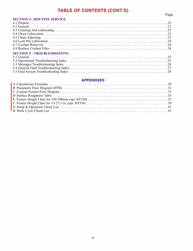
SECTION 4 - ROUTINE SERVICE4.1 Purpose . . . . . . . . . . . . . . . . . . . . . . . . . . . . . . . . . . . . . . . . . . . . . . . . . . . . . . . . . . . . . . . . . . . . . . . . . . . . . .234.2 General . . . . . . . . . . . . . . . . . . . . . . . . . . . . . . . . . . . . . . . . . . . . . . . . . . . . . . . . . . . . . . . . . . . . . . . . . . . . . .234.3 Cleaning And Lubricating . . . . . . . . . . . . . . . . . . . . . . . . . . . . . . . . . . . . . . . . . . . . . . . . . . . . . . . . . . . . . . . .234.4 Chain Lubrication . . . . . . . . . . . . . . . . . . . . . . . . . . . . . . . . . . . . . . . . . . . . . . . . . . . . . . . . . . . . . . . . . . . . . .234.5 Chain Adjusting . . . . . . . . . . . . . . . . . . . . . . . . . . . . . . . . . . . . . . . . . . . . . . . . . . . . . . . . . . . . . . . . . . . . . . . .234.6 Lock Pin Lubrication . . . . . . . . . . . . . . . . . . . . . . . . . . . . . . . . . . . . . . . . . . . . . . . . . . . . . . . . . . . . . . . . . . . .244.7 Coolant Reservoir . . . . . . . . . . . . . . . . . . . . . . . . . . . . . . . . . . . . . . . . . . . . . . . . . . . . . . . . . . . . . . . . . . . . . .244.8 Replace Coolant Filter . . . . . . . . . . . . . . . . . . . . . . . . . . . . . . . . . . . . . . . . . . . . . . . . . . . . . . . . . . . . . . . . . . .24
SECTION 5 - TROUBLESHOOTING5.1 General . . . . . . . . . . . . . . . . . . . . . . . . . . . . . . . . . . . . . . . . . . . . . . . . . . . . . . . . . . . . . . . . . . . . . . . . . . . . . .255.2 Operational Troubleshooting Index . . . . . . . . . . . . . . . . . . . . . . . . . . . . . . . . . . . . . . . . . . . . . . . . . . . . . . . . .255.3 Messages Troubleshooting Index . . . . . . . . . . . . . . . . . . . . . . . . . . . . . . . . . . . . . . . . . . . . . . . . . . . . . . . . . . .265.4 General Fault Troubleshooting Index . . . . . . . . . . . . . . . . . . . . . . . . . . . . . . . . . . . . . . . . . . . . . . . . . . . . . . . .275.5 Feed System Troubleshooting Index . . . . . . . . . . . . . . . . . . . . . . . . . . . . . . . . . . . . . . . . . . . . . . . . . . . . . . . .28
APPENDIXESA Calculations Formulas . . . . . . . . . . . . . . . . . . . . . . . . . . . . . . . . . . . . . . . . . . . . . . . . . . . . . . . . . . . . . . . . . . . .29
B Pneumatic Flow Diagram (HTB) . . . . . . . . . . . . . . . . . . . . . . . . . . . . . . . . . . . . . . . . . . . . . . . . . . . . . . . . . . . .31
C Coolant System Flow Diagram . . . . . . . . . . . . . . . . . . . . . . . . . . . . . . . . . . . . . . . . . . . . . . . . . . . . . . . . . . . . .33
D Surface Roughness Table . . . . . . . . . . . . . . . . . . . . . . . . . . . . . . . . . . . . . . . . . . . . . . . . . . . . . . . . . . . . . . . . . .35
E Fixture Height Chart for 350-700mm (opt. HT350) . . . . . . . . . . . . . . . . . . . . . . . . . . . . . . . . . . . . . . . . . . . . . .37
F Fixture Height Chart for 13-27.5 in. (opt. HT350) . . . . . . . . . . . . . . . . . . . . . . . . . . . . . . . . . . . . . . . . . . . . . .39
G Setup & Operation Check List . . . . . . . . . . . . . . . . . . . . . . . . . . . . . . . . . . . . . . . . . . . . . . . . . . . . . . . . . . . . . .41
H Work Cycle Check List . . . . . . . . . . . . . . . . . . . . . . . . . . . . . . . . . . . . . . . . . . . . . . . . . . . . . . . . . . . . . . . . . . .43
vi
TABLE OF CONTENTS (CONT’D)Page
vii
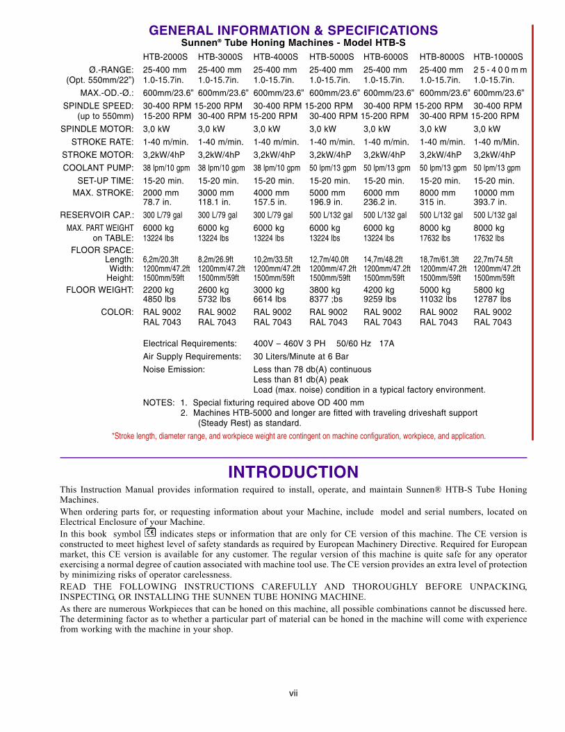
GENERAL INFORMATION & SPECIFICATIONSSunnen® Tube Honing Machines - Model HTB-S
HTB-2000S HTB-3000S HTB-4000S HTB-5000S HTB-6000S HTB-8000S HTB-10000S
Ø.-RANGE: 25-400 mm 25-400 mm 25-400 mm 25-400 mm 25-400 mm 25-400 mm 2 5 - 4 0 0 m m(Opt. 550mm/22”) 1.0-15.7in. 1.0-15.7in. 1.0-15.7in. 1.0-15.7in. 1.0-15.7in. 1.0-15.7in. 1.0-15.7in.
MAX.-OD.-Ø.: 600mm/23.6” 600mm/23.6” 600mm/23.6” 600mm/23.6” 600mm/23.6” 600mm/23.6” 600mm/23.6”
SPINDLE SPEED: 30-400 RPM 15-200 RPM 30-400 RPM 15-200 RPM 30-400 RPM 15-200 RPM 30-400 RPM (up to 550mm) 15-200 RPM 30-400 RPM 15-200 RPM 30-400 RPM 15-200 RPM 30-400 RPM 15-200 RPM
SPINDLE MOTOR: 3,0 kW 3,0 kW 3,0 kW 3,0 kW 3,0 kW 3,0 kW 3,0 kW
STROKE RATE: 1-40 m/min. 1-40 m/min. 1-40 m/min. 1-40 m/min. 1-40 m/min. 1-40 m/min. 1-40 m/Min.
STROKE MOTOR: 3,2kW/4hP 3,2kW/4hP 3,2kW/4hP 3,2kW/4hP 3,2kW/4hP 3,2kW/4hP 3,2kW/4hP
COOLANT PUMP: 38 lpm/10 gpm 38 lpm/10 gpm 38 lpm/10 gpm 50 lpm/13 gpm 50 lpm/13 gpm 50 lpm/13 gpm 50 lpm/13 gpm
SET-UP TIME: 15-20 min. 15-20 min. 15-20 min. 15-20 min. 15-20 min. 15-20 min. 15-20 min.MAX. STROKE: 2000 mm 3000 mm 4000 mm 5000 mm 6000 mm 8000 mm 10000 mm
78.7 in. 118.1 in. 157.5 in. 196.9 in. 236.2 in. 315 in. 393.7 in.
RESERVOIR CAP.: 300 L/79 gal 300 L/79 gal 300 L/79 gal 500 L/132 gal 500 L/132 gal 500 L/132 gal 500 L/132 gal
MAX. PART WEIGHT 6000 kg 6000 kg 6000 kg 6000 kg 6000 kg 8000 kg 8000 kgon TABLE: 13224 lbs 13224 lbs 13224 lbs 13224 lbs 13224 lbs 17632 lbs 17632 lbs
FLOOR SPACE:Length: 6,2m/20.3ft 8,2m/26.9ft 10,2m/33.5ft 12,7m/40.0ft 14,7m/48.2ft 18,7m/61.3ft 22,7m/74.5ftWidth: 1200mm/47.2ft 1200mm/47.2ft 1200mm/47.2ft 1200mm/47.2ft 1200mm/47.2ft 1200mm/47.2ft 1200mm/47.2ft
Height: 1500mm/59ft 1500mm/59ft 1500mm/59ft 1500mm/59ft 1500mm/59ft 1500mm/59ft 1500mm/59ftFLOOR WEIGHT: 2200 kg 2600 kg 3000 kg 3800 kg 4200 kg 5000 kg 5800 kg
4850 lbs 5732 lbs 6614 lbs 8377 ;bs 9259 lbs 11032 lbs 12787 lbs
COLOR: RAL 9002 RAL 9002 RAL 9002 RAL 9002 RAL 9002 RAL 9002 RAL 9002RAL 7043 RAL 7043 RAL 7043 RAL 7043 RAL 7043 RAL 7043 RAL 7043
Electrical Requirements: 400V – 460V 3 PH 50/60 Hz 17A
Air Supply Requirements: 30 Liters/Minute at 6 Bar
Noise Emission: Less than 78 db(A) continuousLess than 81 db(A) peakLoad (max. noise) condition in a typical factory environment.
NOTES: 1. Special fixturing required above OD 400 mm2. Machines HTB-5000 and longer are fitted with traveling driveshaft support
(Steady Rest) as standard.
*Stroke length, diameter range, and workpiece weight are contingent on machine configuration, workpiece, and application.
INTRODUCTIONThis Instruction Manual provides information required to install, operate, and maintain Sunnen® HTB-S Tube HoningMachines.
When ordering parts for, or requesting information about your Machine, include model and serial numbers, located onElectrical Enclosure of your Machine.
In this book symbol indicates steps or information that are only for CE version of this machine. The CE version isconstructed to meet highest level of safety standards as required by European Machinery Directive. Required for Europeanmarket, this CE version is available for any customer. The regular version of this machine is quite safe for any operatorexercising a normal degree of caution associated with machine tool use. The CE version provides an extra level of protectionby minimizing risks of operator carelessness.
READ THE FOLLOWING INSTRUCTIONS CAREFULLY AND THOROUGHLY BEFORE UNPACKING,INSPECTING, OR INSTALLING THE SUNNEN TUBE HONING MACHINE.
As there are numerous Workpieces that can be honed on this machine, all possible combinations cannot be discussed here.The determining factor as to whether a particular part of material can be honed in the machine will come with experiencefrom working with the machine in your shop.

viii
WEI
V E
DIS
WE I
V T
NO
RF
mm 495
).ni 4.32(
1505 mm(59.3 in.)
WEI
V E
DIS
mm 5,0 67
).n i 9.9 2(
mm 5,0801
).ni 3.24(
1725 mm(67.9 in.)
mm 3082
).ni 4.011 (
mm 0009
).ni 3.453(
mm 45 781
).n i 3. 837(
mm 0651
).ni 4.16(m
m 6 641). ni 7.55(
mm 45 03
). ni 2.021 (
mm 2 079
).ni 9 .18 3(
320 mm(12.6 in.)
166.5 mm(6.5 in.)
55 mm(2.1 in.)
1102 mm(43.4 in.)
700 mm
(27.6 in.)
1289 mm(50.7 in.)
1405 mm(55.3 in.)
1725 mm (68 in.)(REQUIRED CLEARANCE WITH
OPTIONAL SWING AWAY HOODS)
mm 023
).ni 6 .21(
ENIL
R ETNE
CEL
DNIPS F
O
Am
m 4503).ni 2.021(
mm 3082
) .ni 4.011(B
:g
nida
oL r
ool
F.)fs/s
bl 151( ms/
gk 937 na
ht sseL :A
).ni 4.54 ( m
m4511
:B
m
m8221
).ni 3.84(
FIGURE 1-A, Floor Plan Layout (System Configuration)

1.1 PURPOSEThis Section is designed to aid the user in theunpacking, inspecting and installing the SUNNENAG NC Tube Honing Machines. Hereafter referredto as the Machines (see Figure 1.1).1.2 SUGGESTED TOOLINGThe following tools are required for unpacking andinstalling the machine:
Knife Cleaning SolventCrowbar Slip Joint PliersHammer Wire Cutters/StrippersTin Snips Screw Driver (Std. Nose)Hex Wrench Metric (supplied)Safety Latch Key (supplied)Open End Wrench (17, 19 + 24 mm)
1.3 INSTALLINGRead the following instructions carefully andthoroughly before unpacking and inspecting theMachine. All references to right and left in theseinstructions are, unless otherwise noted, as seen bythe operator as one looks at the Machine orassembly being described. The Machine is shippedin three (3) separate crates:
1) Carriage Table + Operator Control Panel
2) Mounting Table
3) Coolant Reservoir
1. Remove top and front of shipping crates.
2. Cut, remove and discard shipping bands.
3. Remove Components from the crates.
4. Remove four nuts and bolts (in each crate)securing Tables Support Feet to the bottom of thecrates. Use 17 mm Open end Wrench.
5. Lift Tables and Enclosure from crates usingeyebolts provided.
6. Inspect Machine and Components for dents,scratches, or damage resulting from improperhandling by carrier. If damage is evident,immediately file a claim with carrier.
1.4 LOCATING1. Place Machine in desired location using eyebolts
to lift Machine.
NOTE: The two M16 Bolts for connecting theMounting Table to the Carriage Table are supplied inthe package.
1
FIGURE 1-1, NC Tube Honing Machine
OPERATORSIDE
SECTION 1 -INSTALLATION

2. Align both Tables, and then install M16 Boltsbetween Tables (see Figure 1-2).
CAUTIONDO NOT move Tables once Bolts are installed.Serious damage may be caused to the Tables if theMachine is lifted once Bolts are installed.
3. Align both sections of the Machine. Then place amachinist level on the Body of machine and levelby adjusting the Leveling Bolts on Support Feet(see Figure 1-3) Bolts require a 24 mm Open EndWrench.
4. For permanent installation, secure MachinesSupport Feet to Floor with appropriate fasteners(not supplied).
5. Unscrew lifting devices from the Carriage Table.Retain for future use.
CAUTIONSERIOUS DAMAGE WILL BE CAUSED TO THESPINDLE CARRIAGE IF THE SPINDLECARRIAGE IS INITIALIZED OR MOVEDBEFORE THE LIFTING DEVICES AREREMOVED!
6. Clean Spindle Carriage Ways with solvent toremove anti-rust and any foreign materials. Afterthis, lightly lubricate with Oil.
1.5 INSTALLING COMPONENTS1. Bolt Spindle Drive to Spindle Retractor Carriage
(see Figure 1-4), using four Mounting Bolts(supplied). Requires 19mm Open End Wrench
2
FIGURE 1-2, Connecting Tables
FIGURE 1-4, Spindle Drive
FIGURE 1-3, Leveling Screws
LEVELINGBOLT &LOCKNUT
EYEBOLT
SPINDLEDRIVE
SPINDLERETRACTOR
CARRIAGE
BOLTS

Connect the electrical plug (X 131) from SpindleDrive Motor into the socket in the Carriageconnection Block, on rear of the Spindle Carriage(see Figure 1-5).2. Install Disassembly Ring on Input hub.
Install Remote Feed Unit by turning onto threadedInput Hub.
Install Torque Bracket on Remote Feed Unit asillustrated.
Attach Cable on Remote Feed Unit to 4-PinConnector supplied on Spindle Drive.
CAUTIONDO NOT install the Remote Feed Unit unlessDisassembly Ring is in place on Input Hub.
3. Install Workholding Fixture to Plate on ThreadedColumn and Base Assembly (see Figure 1-6), usingfour Mounting Bolts (supplied). Requires 8 mm HexWrenches.
NOTE: Slot of Plate must be on the opposite ofHand Crank.
4. Install Tool Support Bar as follows (see Figure 1-7).Mount L-Bracket to Rear of Machine, using twoSocket Head Cap screw. Requires 8 mm HexWrenches.
Install Operator Control panel to Machine Base infront of Carriage Table, by using two Cap HeadScrews M12 x 40 (see Figure 1-8).6. Lift the Magnetic Filter into Coolant Reservoir.
Slide Coolant Reservoir into position between centerlegs in the middle of Machine (see Figure 1-9).Connect the oil fitting to the Mounting table.
NOTE: The Coolant Reservoir should be in place,approximately 130 mm behind of the front Line ofmachine. Install Splash Cover on Reservoir. PositionDump Tube over opening in Magnetic Filter. Connectelectrical Plug in Electrical Enclosure (see Figure 1-9).
3
FIGURE 1-6, Workholding Fixture
WORKHOLDINGFIXTURE
THREADEDCOLUMNAND BASE
FIGURE 1-5, Modular Feed System
FIGURE 1-7, Tool Support Bar
FIGURE 1-8, Operator Control Panel
OPERATORCONTROL
PANEL
Mount the pivot armwith four screws
PLUG

7. Position two Splash Guards on Machine. Requires5 mm Hex Wrenches (see Figure 1-10).
1.6 ELECTRICAL CONNECTIONMAIN ELECTRICAL ENCLOSURE For connecting the Electrical Main Enclosure is apre drilled Hole with an Oil thigh Fitting has beenprovided in the Main Electrical Enclosure for theElectrical Supply Cord (not supplied).
NOTE: For Cord dimensions look on GENERALINFORMATION AND SPECIFICATION
1. Unlock door to Electrical Enclosure, using Keysupplied with Machine.
2. Insert electrical supply cord through EntranceHole. Allow for approximately 600 mm of cablefrom were it enter the Enclosure and cut off theexcess.
3. Strip 250 mm off cables outer jacket and Strip 6mm of insulation from each wire.
4. Connect green wire to Terminal PE (EarthGround) and blue wire to E (Zero Point) as noted onBlock.
5. Connect other three wires to the ElectricalDisconnect Block as noted on Block (L1, L2, andL3). Close and lock Door to Main ElectricalEnclosure. Connect Electrical Supply Cord to powersource.
1.7 OPTIONALFILTER UNIT (PF 401)Consult the installation Instructions packaged withthe Filter Unit (see Figure 1-11).
4
FIGURE 1-9, Coolant Reservoir
FIGURE 1-10, Splash Guard
SPLASHGUARD
FIGURE 1-11, Filter Unit
SPLASHCOVER
MAGNETICFILTER
DUMPTUBE
ELECTRICALENCLOSURE

SPECIAL FIXTURE FOR OD ABOVE 400 mm (HT-350) see Fixture Height Chart Section 2-F.
INPROCESS GAGING (IPG-50)
1.8 FILLING FLUIDSHTB-2000,-3000,-4000Maximum capacity of Coolant Reservoir is 300Liters subsequent to running the Coolant pump. Ifequipped with a Filter Unit (PF-401) 30 Liters moreof Coolant may be added. Minimum capacity ofCoolant Reservoir, for proper pump is 170 Liters. Ifequipped with the PF-400 Filter Unit it will be 220Liters
HTB-5000,-6000,-8000,-10’000Maximum capacity of Coolant Reservoir is 500Liters subsequent to running the Coolant pump. Ifequipped with a Filter Unit (PF-401) 30 Liters moreof Coolant may be added. Minimum capacity ofCoolant Reservoir for proper pump is 360 Liters. Ifequipped with the PF-400 Filter Unit it will be 450Liters
1.9. OPERATIONAL CHECK1. Read Sections 1 and 2 thoroughly and carefully
before performing the Operational Check.
2. Operate the Machine and check rotation of theSpindle Shaft. Rotation of the Shaft should beCounterclockwise, as viewed from output end ofSpindle Drive. If rotation is incorrect reverse anytwo wires (red, white, or black) of the electricalsupply cord, where they connect to the ElectricalDisconnect Block.
3. Operate the Machine and check rotation ofoptional equipment according to the InstallationInstruction package with the equipment.
After unpacking and installing the Machine, cleanand lubricate. Refer to Section: 4. ROUTINESERVICE, Cleaning and Lubricating.
5

FIGURE 2-2, Safety Switches
MAINSWITCH
6
FIGURE 2-1, Major Components
SPINDLE GEARADJUSTMENTWHEEL
COOLANTRESERVOIR
E-STOP
SPLASHGUARD
E-STOP
SAFETYLIGHT
BARRIER
SAFETYSWITCH
ACTIVATORS
SAFETY LIGHT BARRIER RECEIVER INDICATION
AMBER LIGHT ON: SENSING FIELD IS UNINTERRUPTEDAND ACTIVE.
AMBER LIGHT FLASHING: SIGNAL STRENGTH IS LOW.CHECK ALIGNMENT AND LENS CLEANLINESS.
AMBER LIGHT OFF: SENSING FIELD HAS BEEN INTERRUPTED OR IS INACTIVE.
2.1 GENERALThis section should be consulted when preparing theMachine for honing. Also read the CONTROLMANUAL carefully before starting Operation.
2.2 MAJOR COMPONENTSFor the location of the major components on theMachine see Figure 2-1.
2.3. LOCATION OF EMERGENCY SWITCHThis Section is designed to show were all ElectricalSwitches are located. Location of:
MAIN SWITCH
SAFETY SWITCH ACTIVATORS (Stroke End Position)
EMERGENCY STOP
SAFETY LIGHT BARRIER
NOTE: NON CE-machines does not have aSAFETY LIGHT BARRIER.
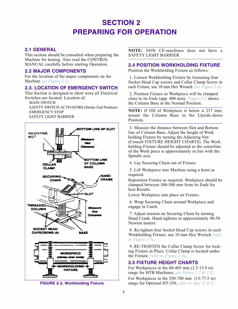
2.4 POSITION WORKHOLDING FIXTUREPosition the Workholding Fixture as follows:
1. Loosen Workholding Fixture by loosening fourSocket Head Cap screws and Collar Clamp Screw ineach Fixture, use 10 mm Hex Wrench (see Figure 2-3).2. Position Fixture so Workpiece will be clamped
close to its Ends (app. 400 mm). Figure 2-3 showsthe Column Base in the Normal Position.
NOTE: If OD of Workpiece is below ø 237 mm,mount the Column Base in the Upside-downPosition.
3. Measure the distance between Slot and Bottomline of Column Base. Adjust the height of Workholding Fixture by turning the Adjusting Nut(Consult FIXTURE HEIGHT CHARTS). The Workholding Fixture should be adjusted so the centerlineof the Work piece is approximately in line with theSpindle axis.
4. Lay Securing Chain out of Fixture.
5. Lift Workpiece into Machine using a hoist asrequired.
Reposition Fixture as required. Workpiece should beclamped between 300-500 mm from its Ends forbest Results.
Lower Workpiece into place on Fixture.
6. Wrap Securing Chain around Workpiece andengage in Catch.
7. Adjust tension on Securing Chain by turningHand Crank. Hand tightens to approximately 40-50Newton meters.
8. Re-tighten four Socket Head Cap screws in eachWorkholding Fixture, use 10 mm Hex Wrench (referto Figure 2-3).9. RE-TIGHTEN the Collar Clamp Screw for lock-
ing Fixture in Place. Collar Clamp is located underthe Fixture (refer to Figure 2-3).2.5 FIXTURE HEIGHT CHARTSFor Workpieces in the 60-405 mm (2.3-15.9 in)range for HTB Machines, see Tables 2-1 & 2-2.
For Workpieces in the 350-700 mm (13-77.5 in)range for Optional HT-350, refer to App. E & F.
7
SECTION 2 -PREPARING FOR OPERATION
FIGURE 2-3, Workholding Fixture

NOTE: All measurements shown are for Out SideDiameter in Millimeters.
2.6 ASSEMBLY & INSTALL HONING TOOLAssembly and install Honing Tool per instructionspackaged with Tooling.
1. Assemble Honing Tool (see Figure 2-4).2. Press UNLOCK CARRIAGE Key and slide
Spindle Retractor Carriage to the left.
8
TABLE 2-1, Fixture Height Chart for ø 60 - 415 mm (HTB Machines)
+mm 60 90 120 150 180 210 240 270 300
0 286 270 254 236 218 202 184 167 150
3 284 268 252 234 217 200 182 165 149
6 283 266 250 232 216 197 180 163 147
9 281 264 248 231 214 196 178 161 145
12 279 262 247 229 212 194 177 160 143
15 278 261 245 227 210 192 176 158 142
18 276 259 243 225 208 190 174 156 140
21 274 257 241 224 207 188 172 155 138
24 273 255 240 222 205 187 170 154 ---
27 272 253 238 220 203 186 168 152 ---
O.D. from ø 60 - 321mm
This Side of the Chart is by using the Column Base in the
Upside-Down Position.
180 210 240 270 300 330 360 390
195 177 160 142 126 108 88 70
193 176 158 141 124 106 86 69
192 174 156 140 122 105 84 68
190 172 154 138 120 103 83 66
187 170 153 136 118 101 81 64
186 168 151 135 116 99 79 63
184 167 149 133 114 97 77 ---
182 165 147 131 112 95 75 ---
180 163 146 129 111 93 73 ---
178 161 144 128 110 91 71 ---
O.D. from ø 180 - 405mm
This Side of the Chart is by using the Column Base in the
Normal Position.
HOW TO USE FIXTURE HEIGHT CHART
Find Work piece O.D. by reading across the top and down the left side of the chart. Where the column andline intersect is the approximate height at which the fixture should be set.
EXAMPLE: OD of Work piece is 192 mm
Find column 180 mm on top of chart, move down the column until it intersects line 12. For this example theFixture should be set at 212 mm.
FIGURE 2-4, Honing Tool
STONE

NOTE: The Spindle Retractor Carriage provides 380mm of tool withdrawal motion.
3. Swing Tool Support Bar into load position andtighten Adjustment Handle. Adjust height byloosening Collar Clamp and raising or lowering asrequired (see Figure 2-5).4. Rest Honing Tool on Tool Support Bar.
5. Align Input Yoke Adapter on Honing Tool withDrive Ring, and guide adapter onto Hex Shaft (seeFigure 2-6).
9
FIGURE 2-5, Tool Support Bar
TABLE 2-2, Fixture Height Chart for ø 2.3 - 15.9 in. (HTB Machines)
+in. 2.3 3.5 4.7 5.9 7.1 8.3 9.5 10.6 11.8
0 11.3 10.6 10.0 9.29 8.58 7.95 7.24 6.57 5.91
0.1 11.2 10.6 9.9 9.21 8.54 7.87 7.17 6.50 5.87
0.2 11.1 10.5 9.8 9.13 8.50 7.76 7.09 6.42 5.79
0.3 11.1 10.4 9.8 9.09 8.43 7.72 7.01 6.34 5.71
0.4 11.0 10.3 9.7 9.02 8.35 7.64 6.97 6.30 5.63
0.5 10.9 10.3 9.6 8.94 8.27 7.56 6.93 6.22 5.59
0.6 10.9 10.2 9.6 8.86 8.19 7.48 6.85 6.14 5.51
0.8 10.8 10.1 9.5 8.82 8.15 7.40 6.77 6.10 5.43
0.9 10.7 10.0 9.4 8.74 8.07 7.36 6.69 6.06 5.35
1 10.7 10.0 9.4 8.66 7.99 7.32 6.61 5.98 5.28
O.D. from ø 2.3 - 12.2 inches
This Side of the Chart is by using the Column Base in the
Upside-Down Position.
7.0 8.3 9.5 10.6 11.8 13.0 14.2 15.4
7.68 6.97 6.30 5.59 4.96 4.25 3.46 2.76
7.60 6.93 6.22 5.55 4.88 4.17 3.39 2.72
7.56 6.85 6.14 5.51 4.80 4.13 3.31 2.68
7.48 6.77 6.06 5.43 4.72 4.06 3.27 2.60
7.36 6.69 6.02 5.35 4.65 3.98 3.19 2.52
7.32 6.61 5.94 5.31 4.57 3.90 3.11 2.48
7.24 6.57 5.87 5.24 4.49 3.82 3.03 0.00
7.17 6.50 5.79 5.16 4.41 3.74 2.95 0.00
7.09 6.42 5.75 5.08 4.37 3.66 2.87 0.00
7.01 6.34 5.67 5.04 4.33 3.58 2.80 0.00
O.D. from ø 7.0 - 15.9 mm
This Side of the Chart is by using the Column Base in the
Normal Position.
HOW TO USE FIXTURE HEIGHT CHART
Find Work piece O.D. by reading across the top and down the left side of the chart. Where the column andline intersect is the approximate height at which the fixture should be set.
EXAMPLE: OD of Work piece is 7.5 inches
Find column 7.1 in. on top of chart, move down the column until it intersects line 0.4. For this example theFixture should be set at 8.35 in.
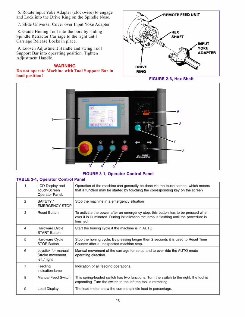
6. Rotate input Yoke Adapter (clockwise) to engageand Lock into the Drive Ring on the Spindle Nose.
7. Slide Universal Cover over Input Yoke Adapter.
8. Guide Honing Tool into the bore by slidingSpindle Retractor Carriage to the right untilCarriage Release Locks in place.
9. Loosen Adjustment Handle and swing ToolSupport Bar into operating position. TightenAdjustment Handle.
WARNINGDo not operate Machine with Tool Support Bar inload position!
10
FIGURE 2-6, Hex Shaft
1 LCD Display and Operation of the machine can generally be done via the touch screen, which meansTouch-Screen that a function may be started by touching the corresponding key on the screenOperator Panel.
2 SAFETY / Stop the machine in a emergency situationEMERGENCY STOP
3 Reset Button To activate the power after an emergency stop, this button has to be pressed when ever it is illuminated. During initialization the lamp is flashing until the procedure is finished.
4 Hardware Cycle Start the honing cycle if the machine is in AUTOSTART Button
5 Hardware Cycle Stop the honing cycle. By pressing longer then 2 seconds it is used to Reset Time STOP Button Counter after a unexpected machine stop.
6 Joystick for manual Manual movement of the carriage for setup and to over ride the AUTO mode Stroke movement operating direction.left / right
7 Feeding Indication of all feeding operations.indication lamp
8 Manual Feed Switch This spring-loaded switch has two functions. Turn the switch to the right, the tool is expanding. Turn the switch to the left the tool is retracting.
9 Load Display The load meter show the current spindle load in percentage.
TABLE 3-1, Operator Control PanelFIGURE 3-1, Operator Control Panel
2
1
3 4 5
8
6
9
7

3.1 GENERALThis section describes a step-by-step operatingprocedure for the HTB-S TUBE HONINGMACHINES. Prior to start with setup and operationall prerequisites described in Sections 1 and 2 havecompleted:
For the daily use, this document is not intendedbecause of the fact, that the control is almost self-explaining. After a short introduction, almosteverybody is able to start the machine without thismanual or with the short instruction guide (use 5.7Setup & Operation Check List). However, werecommend, that everybody read this manual inorder to get more background information and toget to know the special functions, which may be ofgreat help for the daily use.
Operation of the machine can generally be done viathe touch screen, which means that a function maybe started by touching the corresponding key on thescreen. The number of hardware keys is limited.
3.2 SAFETY PRECAUTIONSThe following precautions should be followed toensure maximum safety of personnel while workingon or around the HTB-S TUBE HONINGMACHINE.
• DO NOT initialize the system with a connectedhoning tool.
• DO NOT operate Machine with Tool SupportBar in load position.
• DO NOT adjust stroke length while SpindleRetractor Carriage is not locked position.
• Stay clear of all moving parts.
• Remove keys and wrenches from machinebefore honing.
3.3 OPERATOR CONTROL PANELYou will find the main control elements marked anddescribed in Figure 3-1 and Table 3-1.
3.4 MAIN SCREEN (TOUCH SCREEN)(Touch Screen) - All of the following functions andsetups are accessible or can switched ON (key haswhite ground color) and OFF (key has grey groundcolor) by pressing the key with the appropriate indi-cation or text on the screen. Several values can bechanged easily by pressing direct into the text field.
The main screen appears as soon as the machine isswitched on. All necessary parameters forproduction are shown in Figure 3-2 and Table 3-2.
3.5 PREPARING FOR START1. Ensure all guards are in place before operating.
2. Ensure area is clear of other personnel beforeoperating machine.
3. Keep loose tools and other foreign objects clearof machine.
4. Wear proper safety items such as, safety glasses,gloves, non-slip safety shoes and other personalsafety equipment as necessary or required.
5. DO NOT wear loose fitting clothes or jewelrywhile working on or around machine.
6. When lifting Work piece or tooling use properlifting procedures.
7. Push E-STOP Button and turn OFF the MainSwitch when ever performing service and no poweris needed.
8. Turn OFF electrical power at Main PowerSource when performing maintenance on orcleaning of Electrical Enclosure.
9. Clean up lubricant spills immediately.
3.5.1 INITIALIZING
PRECAUTIONBefore initializing the machine disconnect anymounted honing tool from the carriage.
Prior to start setup and production, the machinemust be initialized. Turn the Main Power switch ONand press the RESET Button until the blue illumina-tion switched off. Then press the initializing key onthe touch screen, the carriage moves in left directionduring this procedure the blue light on the RESETButton is flashing until the zero position (Sensor) isreached.
NOTICE: An override is not possible.
Initialize: This key is to initialize thesystem, the carriage moves in leftdirection to the zero position.
Notice: The key occurs only on screen if itis necessary to initialize the system.
3.6 BASIC MENU (Manual & Auto Modes)For easier understanding the button with the signsinstead of text are placed beside the main panelpicture (see Figure 3-3 & Tables 3-3).
11
SECTION 3 -SETUP & OPERATION
12
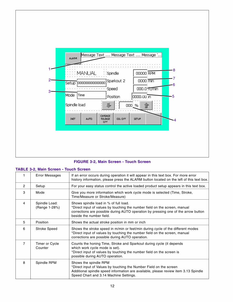
1 Error Messages If an error occurs during operation it will appear in this text box. For more error history information, please press the ALARM button located on the left of this text box.
2 Setup For your easy status control the active loaded product setup appears in this text box.
3 Mode Give you more information which work cycle mode is selected (Time, Stroke, Time/Measure or Stroke/Measure)
4 Spindle Load: Shows spindle load in % of full load.(Range 1-28%) *Direct input of values by touching the number field on the screen, manual
corrections are possible during AUTO operation by pressing one of the arrow button beside the number field.
5 Position Shows the actual stroke position in mm or inch
6 Stroke Speed Shows the stroke speed in m/min or feet/min during cycle of the different modes*Direct input of values by touching the number field on the screen, manual corrections are possible during AUTO operation.
7 Timer or Cycle Counts the honing Time, Stroke and Sparkout during cycle (it depends Counter which work cycle mode is set).
*Direct input of values by touching the number field on the screen is possible during AUTO operation.
8 Spindle RPM Shows the spindle RPM*Direct input of Values by touching the Number Field on the screenAdditional spindle speed information are available, please review item 3.13 Spindle Speed Chart and 3.14 Machine Settings.
TABLE 3-2, Main Screen - Touch Screen
FIGURE 3-2, Main Screen - Touch Screen
2
1
6
5
7
4
3
8
13
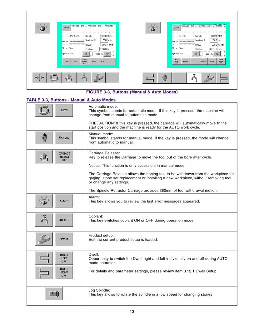
FIGURE 3-3, Buttons (Manual & Auto Modes)
Automatic mode:This symbol stands for automatic mode. If this key is pressed, the machine will change from manual to automatic mode.
PRECAUTION: If this key is pressed, the carriage will automatically move to the start position and the machine is ready for the AUTO work cycle.
Manual mode:This symbol stands for manual mode. If the key is pressed, the mode will change from automatic to manual.
Carriage Release:Key to release the Carriage to move the tool out of the bore after cycle.
Notice: This function is only accessible in manual mode.
The Carriage Release allows the honing tool to be withdrawn from the workpiece for gaging, stone set replacement or installing a new workpiece, without removing tool or change any settings.
The Spindle Retractor Carriage provides 380mm of tool withdrawal motion.
Alarm:This key allows you to review the last error messages appeared.
Coolant:This key switches coolant ON or OFF during operation mode.
Product setup:Edit the current product setup is loaded.
Dwell:Opportunity to switch the Dwell right and left individually on and off during AUTO mode operation.
For details and parameter settings, please review item 3.12.1 Dwell Setup
Jog Spindle:This key allows to rotate the spindle in a low speed for changing stones
TABLE 3-3, Buttons - Manual & Auto Modes
3.6.1 PRODUCT SETUP FILE HANDLING
Press on main screen, go to
and press to get to the product setupfiles on screen (see Table 3-4).
3.7 CREATE A NEW PRODUCT SETUPFor any further progress it is necessary the mainpower is switched on, emergency stop is released,the RESET button is not illuminated, no errormessage appears and the system has successfullyinitialized according item 3.5.
This chapter describes the procedure to create a newproduct setup for a new workpiece.
The complete procedure is in the called teach-inmethod, it means you operate the machine manuallyto a certain point, which then has to be set andstored in the recipe. A new workpiece containindividual setup values.
3.8 STROKE FUNCTION
Press on main screen and then press
to reach the screen (see Figure 3-4 &Tables 3-5 & 3-6).
14
Open:Open an existing product setup. Press this key to display the existing product setups.
Save:Save current product (workpiece) parameters. Press this key to display the existing product setups.
Delete:Delete an existing product setup. Press this key to display the existing product setups.
Save as:Store current product (workpiece) parameter setting as a new product setup. Press this key to display the existing product setups.
Yes:To confirm the action.
Exit:To exit the file handling menu.
TABLE 3-4, Buttons - Setup File Handling
FIGURE 3-4, Operating Screen - Stroke Functions
2
1
2
43

3.8.1 STROKE SETUP
1. Use the Joystick and press it to movecarriage far enough to the right until the honing toolcan be connected.
2. Expand stones in workpiece bore with ManualFeed Switch until the stones touches lightly theinside of the bore.
3. Use the Joystick and press it to move thehoning tool to the left end of the workpiece; thenadd ¼ of Stone length to allow for overstroke.
4. Set the left Stroke Start Position by pressing on screen.
5. Adjust the left SAFETY STOP manually.
6. Use the Joystick and press it to move thehoning tool to the right end of the workpiece; thenadd ¼ of Stone length to allow for overstroke.
7. Set Stroke End Position by pressing onscreen.
8. Adjust the right SAFETY STOP manually.
3.8.2 HOW TO USE THE STEADY SET(OPTIONAL FUNCTION)A Steady Set is recommended for stroke lengthmore then 5000 mm.
1. Mount the Steady Set mechanically
2. Move the tool to the right until you reached therequired (half tool length) steady rest position.
3. Store the Steady Set position by pressing the
and activate it by pressing the key.
15
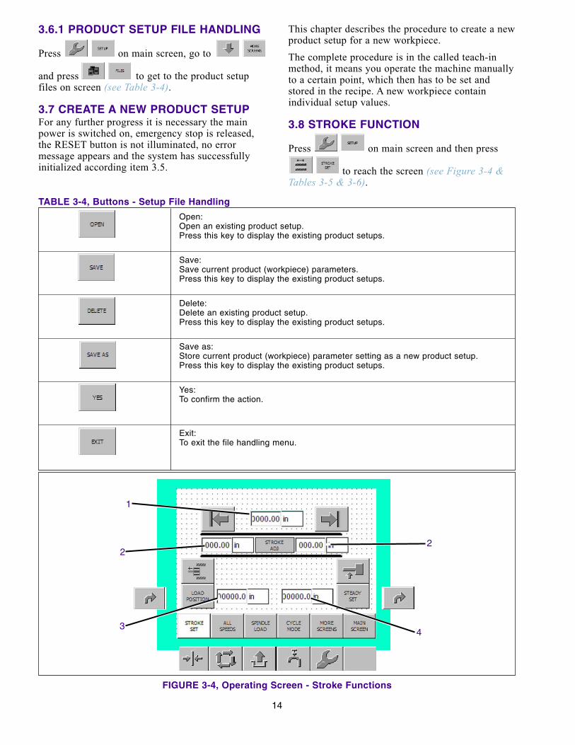
1 Stroke length Display and edit of the current stroke positions.*Direct input of values by touching the number field on the screen.
2 Stroke Correction Display and edit of the current stroke positions.Position left & right *Direct input of values by touching the number field on the screen.
PRECAUTION: Positive correction values will always cause more stroke distance and negative less stroke distance.
3 Current LOAD Display of the current load position.POSITION *Direct input of values by touching the number field on the screen.
4 Current STEADY Display of the current steady set position.SET position *Direct input of values by touching the number field on the screen.
TABLE 3-5, Operating Screen - Stroke Functions
Set left stroke position:Set the left stroke position by moving the carriage with the joystick to the correct position and press this key.
Set right stroke position:Set the right stroke position by moving the carriage with the joystick to the correct position and press this key.
Load Position (Optional function):Mount the park bush on correct position and set the position with this key.
Steady Set (Optional function):Mount the steady set on correct position and set the position with this key.Recommended for stroke length more then 5000 mm.
Load Position (Optional function):Switch the Load Position with this key ON or OFF.
Steady Set (Optional function):Switch the Steady Set with this key ON or OFF.Recommended for stroke length more then 5000 mm.
TABLE 3-6, Buttons - Stroke Functions

3.8.3 HOW TO USE THE LOAD POSITION(OPTIONAL FUNCTION)To use the load option proceed as follows (seeFigure 3-5). The two possibilities are:
CAUTIONActivate this function only with Park Bush or SteadySet, otherwise it can cause personal injury ormachine damage!
A. WITH PARK BUSHING: Park bushing must bein front of the part. Set the LOAD Position into thepark bushing.
The very last stroke of the cycle ends into the parkbushing.
Tool will stop outside of the bore
B. WITHOUT PARK BUSHING: Set the LOADPosition that the tool is still 10 to 20mm into thebore. After this it should be much easier to take outthe tool without making scratches to the surface.
Tool will stop inside of the bore
3.9 ALL SPEEDS SETUP
Press on main screen and then press
to reach the screen (see Figure 3-6 & Table 3-7).
16
FIGURE 3-5, Load Position
A
B
PARKBUSHING
FIGURE 3-6, Operating Screen - Speed Setup
1
1 Stroke speed for time/stroke mode: (Range 1-38 m/min.; 3-124.6 ft/min.) Display and edit the current stroke speed for honing time or stroke operation.
For additional stroke speed information see item 3.14 Machine Settings.
2 Stroke speed for measure mode: (Range 1-38 m/min.; 3-124.6 ft/min.) Display and edit the current stroke speed for stroke operation during measure mode.
3 Stroke speed for sparkout: (Range 1-38 m/min.; 3-124.6 ft/min.) Display and edit the current stroke speed for sparkout operation.
4 Diameter workpiece: (Range 10-1000mm) Display and edit the current workpiece diameter. The diameter setting is the base parameter for the Spindle speed. Your spindle speed setting will change if you change the diameter. The diameter has to be set according the current workpiece diameter.
For additional information see item 3.13 Spindle Speed Chart
5 Gear step position: Display the recommended gear step position it has to be set manually on the handwheel located at the spindle drive. This parameter is non-accessible to overwrite.
Hand wheel adjustment range 1-10
TABLE 3-7, Operating Screen - Speed Setup
5
4
3
2
3.10 SPINDLE LOAD SETUP
Press on main screen and then press
to reach the screen (see Figure 3-7 & Table 3-8).
3.11 CYCLE MODE SETUP
Press on main screen and then press
to reach the screen (see Figure 3-8 & Table 3-9).
17
FIGURE 3-7, Operating Screen - Spindle Load Setup
1
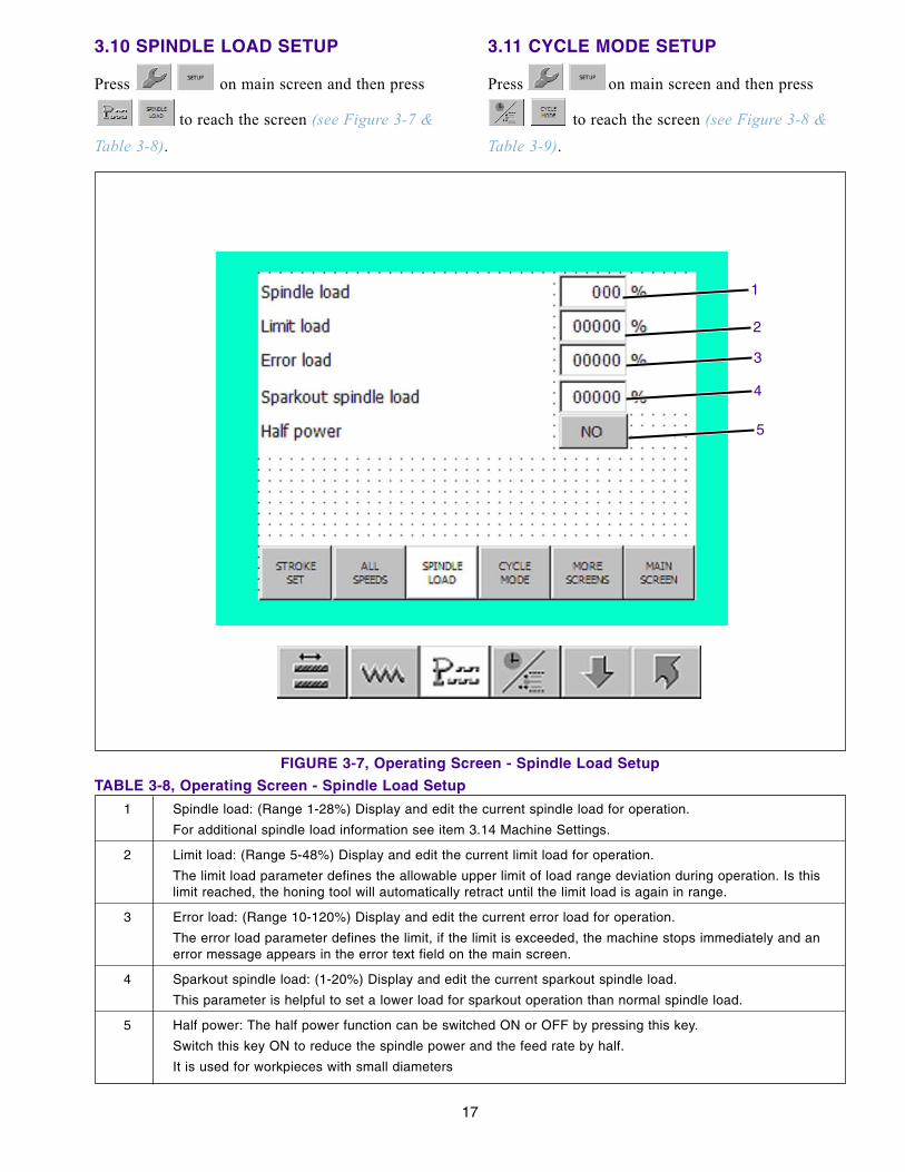
1 Spindle load: (Range 1-28%) Display and edit the current spindle load for operation.
For additional spindle load information see item 3.14 Machine Settings.
2 Limit load: (Range 5-48%) Display and edit the current limit load for operation.
The limit load parameter defines the allowable upper limit of load range deviation during operation. Is this limit reached, the honing tool will automatically retract until the limit load is again in range.
3 Error load: (Range 10-120%) Display and edit the current error load for operation.
The error load parameter defines the limit, if the limit is exceeded, the machine stops immediately and an error message appears in the error text field on the main screen.
4 Sparkout spindle load: (1-20%) Display and edit the current sparkout spindle load.
This parameter is helpful to set a lower load for sparkout operation than normal spindle load.
5 Half power: The half power function can be switched ON or OFF by pressing this key.
Switch this key ON to reduce the spindle power and the feed rate by half.
It is used for workpieces with small diameters
TABLE 3-8, Operating Screen - Spindle Load Setup
5
4
3
2
18
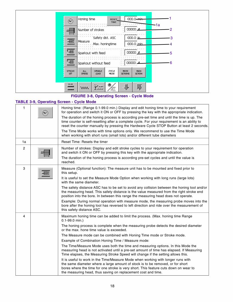
FIGURE 3-8, Operating Screen - Cycle Mode
1a
1
1 Honing time: (Range 0.1-99.0 min.) Display and edit honing time to your requirement for operation and switch it ON or OFF by pressing the key with the appropriate indication.
The duration of the honing process is according pre-set time and until the time is up. The time counter is self-resetting after a complete cycle. For your requirement is an ability to reset the counter manually by pressing the Hardware Cycle STOP Button at least 2 seconds.
The Time Mode works with time options only. We recommend to use the Time Mode when working with short runs (small lots) and/or different tube diameters
1a Reset Time: Resets the timer
2 Number of strokes: Display and edit stroke cycles to your requirement for operation and switch it ON or OFF by pressing this key with the appropriate indication.
The duration of the honing process is according pre-set cycles and until the value is reached.
3 Measure (Optional function): The measure unit has to be mounted and fixed prior to this setup.
It is useful to set the Measure Mode Option when working with long runs (large lots) with the same diameter.
The safety distance ASC has to be set to avoid any collision between the honing tool and/orthe measuring head. This safety distance is the value measured from the right stroke end position into the bore. In between this range the measuring head does not operate.
Example: During normal operation with measure mode, the measuring probe moves into thebore after the honing tool has reversed to left direction and ride over the measurement ofthis safety distance ASC.
4 Maximum honing time can be added to limit the process. (Max. honing time Range 0.1-99.0 min.)
The honing process is complete when the measuring probe detects the desired diameter or the max. hone time value is exceeded.
The Measure mode can be combined with Honing Time mode or Stroke mode.
Example of Combination Honing Time / Measure mode:
The Time/Measure Mode uses both the time and measuring options. In this Mode the measuring head is not activated until a pre-set amount of time has elapsed. If Measuring Time elapses, the Measuring Stroke Speed will change if the setting allows this.
It is useful to work in the Time/Measure Mode when working with longer runs with the same diameter where a large amount of stock is to be removed, or for short bores where the time for one stroke is very short. This feature cuts down on wear to the measuring head, thus saving on replacement cost and time.
TABLE 3-9, Operating Screen - Cycle Mode
5
6
4
3
2

3.12 MORE SCREENS (ADDITIONAL SETTINGS)
3.12.1 DWELL SETUPThe following instruction is mostly used for blindbore applications.
Press on main screen, go to
and press to reach the screen (seeFigure 3-9 & Table 3-10).
Dwell: Opportunity to switch theDwell right and left individuallyOn and OFF.If dwell has been activated theparameter set according item 1-3will be used for AUTO mode.
During AUTO cycle, the same keys are available onthe main screen to switch this function to your need.
NOTICE: The parameters are only accessible in thisdwell setup menu.
19
5 Sparkout with feed: (Max. honing time Range 0.1-99.0 min.)
Display and edit sparkout cycle with feed to your requirement for operation and switch it ON or OFF by pressing the key with the appropriate indication.
After running the cycle by one of the above sizing methods (1-3) the run out cycles will goon according the pre-set power setting (item 3.10) and the cycle amount in this input field.
In this sparkout with feed cycle the tool expands when the power is below the pre-set power setting.
6 Sparkout without feed: Display and edit sparkout cycle without feed to your requirement for operation and switch it ON or OFF by pressing the key with the appropriate indication or text.
After running the cycle by one of the above sizing methods (1-3) the run out cycles will go on according the pre-set cycle amount in this input field.
In this sparkout without feed cycle the tool does not expand when the power is below the pre-set power setting.
TABLE 3-9, Operating Screen - Cycle Mode (cont’d)
1 Dwell time: (Range 0.1-10 sec.)
Display and edit the current dwell time.
The current dwell time settings will be used if the associated key Dwell right / left is enabled.
2 Dwell distance:
Display and edit the current dwell distance.
The current dwell distance settings will be used if the associated key Dwell right / left is enabled.
3 Dwell frequency: (Range 1-20)
Display and edit the current stroke amount is used for dwell mode.
The current dwell frequency settings will be used if the associated key Dwell right / left is enabled.
TABLE 3-10, Operating Screen - Dwell Setup
FIGURE 3-9, Operating Screen - Dwell Setup
1
3
2
1
3
2
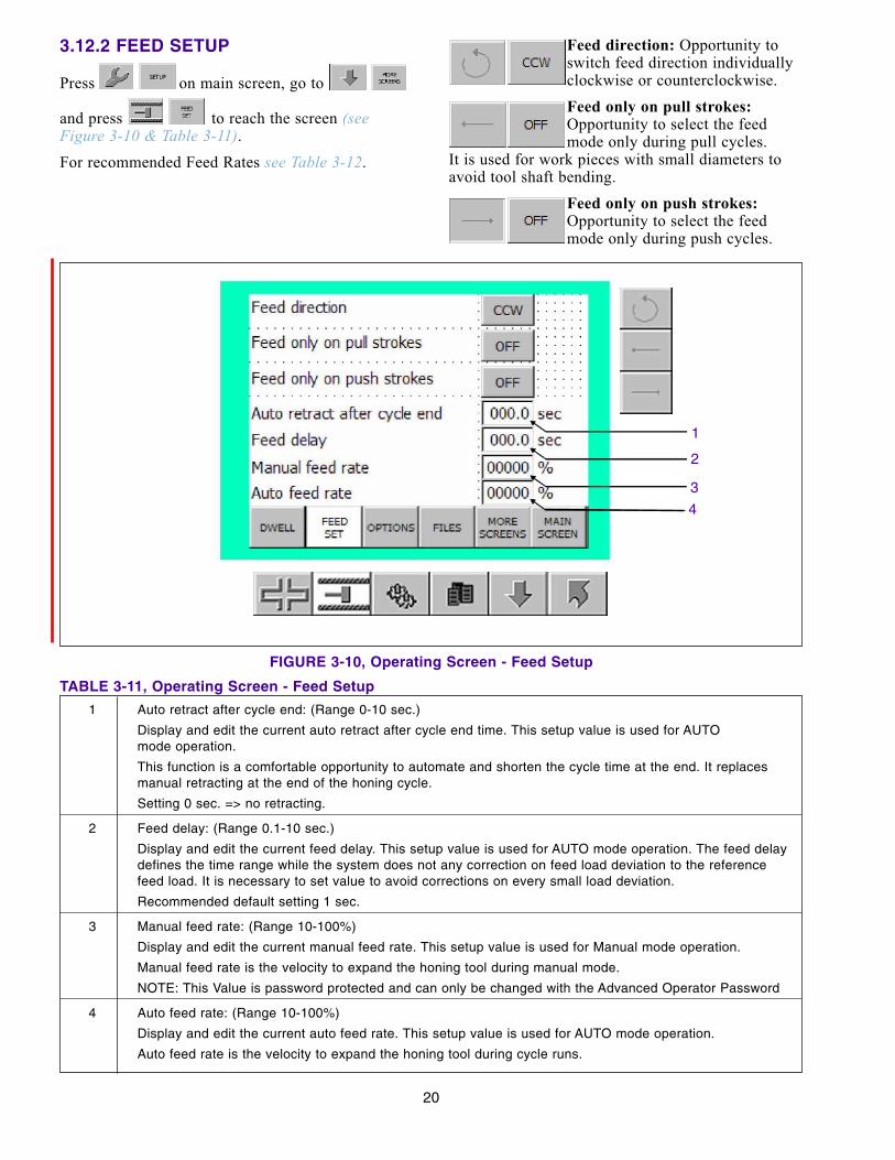
3.12.2 FEED SETUP
Press on main screen, go to
and press to reach the screen (seeFigure 3-10 & Table 3-11).For recommended Feed Rates see Table 3-12.
Feed direction: Opportunity toswitch feed direction individuallyclockwise or counterclockwise.
Feed only on pull strokes:Opportunity to select the feedmode only during pull cycles.
It is used for work pieces with small diameters toavoid tool shaft bending.
Feed only on push strokes:Opportunity to select the feedmode only during push cycles.
20
1 Auto retract after cycle end: (Range 0-10 sec.)
Display and edit the current auto retract after cycle end time. This setup value is used for AUTO mode operation.
This function is a comfortable opportunity to automate and shorten the cycle time at the end. It replaces manual retracting at the end of the honing cycle.
Setting 0 sec. => no retracting.
2 Feed delay: (Range 0.1-10 sec.)
Display and edit the current feed delay. This setup value is used for AUTO mode operation. The feed delay defines the time range while the system does not any correction on feed load deviation to the reference feed load. It is necessary to set value to avoid corrections on every small load deviation.
Recommended default setting 1 sec.
3 Manual feed rate: (Range 10-100%)
Display and edit the current manual feed rate. This setup value is used for Manual mode operation.
Manual feed rate is the velocity to expand the honing tool during manual mode.
NOTE: This Value is password protected and can only be changed with the Advanced Operator Password
4 Auto feed rate: (Range 10-100%)
Display and edit the current auto feed rate. This setup value is used for AUTO mode operation.
Auto feed rate is the velocity to expand the honing tool during cycle runs.
TABLE 3-11, Operating Screen - Feed Setup
FIGURE 3-10, Operating Screen - Feed Setup
1
4
3
2
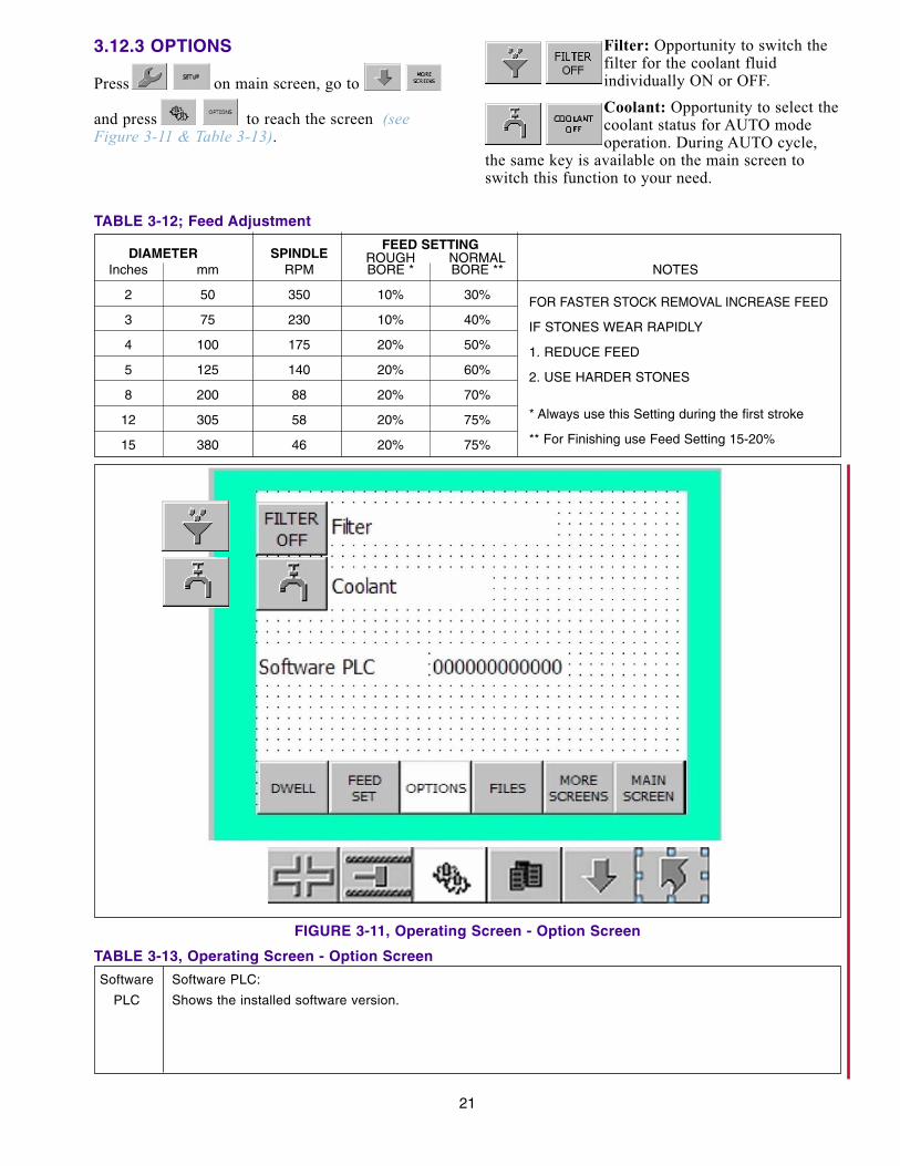
3.12.3 OPTIONS
Press on main screen, go to
and press to reach the screen (seeFigure 3-11 & Table 3-13).
Filter: Opportunity to switch thefilter for the coolant fluidindividually ON or OFF.
Coolant: Opportunity to select thecoolant status for AUTO modeoperation. During AUTO cycle,
the same key is available on the main screen toswitch this function to your need.
21
DIAMETER SPINDLEFEED SETTING
ROUGH NORMALInches mm RPM BORE * BORE ** NOTES
2 50 350 10% 30% FOR FASTER STOCK REMOVAL INCREASE FEED3 75 230 10% 40% IF STONES WEAR RAPIDLY4 100 175 20% 50% 1. REDUCE FEED5 125 140 20% 60% 2. USE HARDER STONES8 200 88 20% 70%
12 305 58 20% 75% * Always use this Setting during the first stroke
15 380 46 20% 75% ** For Finishing use Feed Setting 15-20%
TABLE 3-12; Feed Adjustment
FIGURE 3-11, Operating Screen - Option Screen
Software Software PLC:
PLC Shows the installed software version.
TABLE 3-13, Operating Screen - Option Screen

3.13 SPINDLE SPEED CHARTFor recommended Spindle Speed see Table 3-14.
Metric - Calculate Optimum Spindle Speed: 17500 = RPMBORE DIAMETER (in Millimeters)
Inches - Calculate Optimum Spindle Speed: 689 = RPM
BORE DIAMETER (in inches)
3.14 MACHINE SETTINGSThe Machine Settings in this section are offered as asuggested starting point. Experience with yourparticular operation will dictate the most economicsettings for your shop.
1. STROKE SPEED (m/min)Set the Stroke Speed by pressing STROKE SPEED.For starting a new bore without a previous honingoperation start with approximately 15m/min. after afew strokes increase to 25-32m/min.
2. SPINDLE SPEED (RPM)Set the correct workpiece diameter in the setupscreen and adjust the HAND WHEEL ON THESPINDLE DRIVE to the recommended Numberappears in the field gear step position.
The optimum cutting Speed is about 55m/min.(refer to Table 3-14, Spindle Speed).3. FEED SETTING’S
For the recommended Feed Rate refer to Table 3-12,Feed Adjustment.
NOTE: For other calculation formulas such as:Stock removal, Honing Time, Surface Finish, StoneConsumption and Crosshatch Angle refer to item 5.6CALCULATIONS FORMULAS.
22
SPINDLE-SPEED IN RPMø in mm (in.) RPM ø in mm (in.) RPM ø in mm (in.) RPM
under 40 (1.5”) 430 1 155 (6.1”) 113 360 (14.2”) 48
45 (1.8”) 388 160 (6.3”) 110 380 (15.0”) 46
50 (2.0”) 350 165 (6.5”) 106 400 (15.7”) 44
55 (2.2”) 318 170 (6.7”) 103 425 (16.7”) 41
60 (2.4”) 292 175 (6.9”) 100 450 (17.7”) 39
65 (2.6”) 270 180 (7.1”) 97 475 (18.7”) 37
70 (2.7”) 250 185 (7.3”) 95 500 (19.7”) 35
75 (2.9”) 233 190 (7.5”) 92 525 (20.7”) 33
80 (3.1”) 219 195 (7.7”) 90 550 (21.6”) 31
85 (3.3”) 206 200 (7.9”) 88 575 (22.6”) 30
90 (3.5”) 195 210 (8/3”) 84 600 (23.6”) 29
100 (3.9”) 175 220 (8.7”) 80 625 (24.6”) 28
105 (4.1”) 167 230 (9.0”) 76 650 (25.6”) 27
110 (4.3”) 160 240 (9.4”) 73 675 (26.6”) 26
115 (4.5”) 152 250 (9.8”) 70 700 (27.5”) 25
120 (4.7”) 146 260 (10.2”) 67 725 (28.5”) 24
125 (4.9”) 140 270 (10/6”) 65 750 (29.5”) 23
130 (5.1”) 135 280 (11.0”) 63 800 (31.5”) 22
135 (5.3”) 130 290 (11.4”) 60 850 (33.5”) 21
140 (5.5”) 125 300 (11.8”) 58 900 (35.4”) 20
145 (5.7”) 121 320 (12.5”) 55 950 (37.4”) 18,5
150 (6.3”) 117 340 (13.4”) 51 1000 (39.4”) 17,5
TABLE 3-14, Spindle Speed
4.1 PURPOSEThis section gives suggested routine service andmaintenance instructions.
4.2 GENERALThe following procedures and suggested mainte-nance periods are given as guides only and are notto be construed as absolute or invariable. Local con-ditions must always be considered. Each machinemust be maintained individually, according to itsparticular requirements.
WARNINGTURN THE DISCONNECT SWITCH AND THEELECTRICAL AT THE MAIN POWERSOURCE OFF BEFORE SERVICING!
4.3 CLEANING AND LUBRICATING1. MACHINE EXTERIOR: Clean exterior of the
Machine with warm water and a mild detergent ormild industrial solvent. Rinse thoroughly with cleanhot water and wipe it dry.
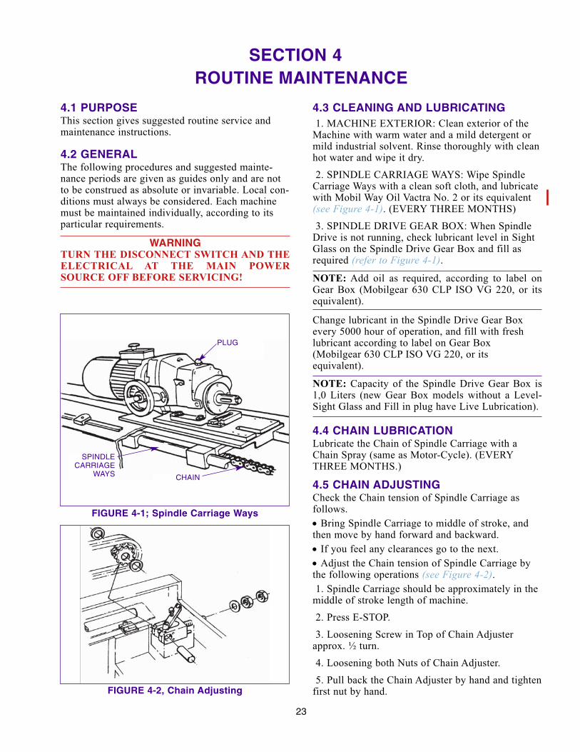
2. SPINDLE CARRIAGE WAYS: Wipe SpindleCarriage Ways with a clean soft cloth, and lubricatewith Mobil Way Oil Vactra No. 2 or its equivalent(see Figure 4-1). (EVERY THREE MONTHS)
3. SPINDLE DRIVE GEAR BOX: When SpindleDrive is not running, check lubricant level in SightGlass on the Spindle Drive Gear Box and fill asrequired (refer to Figure 4-1).
NOTE: Add oil as required, according to label onGear Box (Mobilgear 630 CLP ISO VG 220, or itsequivalent).
Change lubricant in the Spindle Drive Gear Boxevery 5000 hour of operation, and fill with freshlubricant according to label on Gear Box(Mobilgear 630 CLP ISO VG 220, or its equivalent).
NOTE: Capacity of the Spindle Drive Gear Box is1,0 Liters (new Gear Box models without a Level-Sight Glass and Fill in plug have Live Lubrication).
4.4 CHAIN LUBRICATIONLubricate the Chain of Spindle Carriage with aChain Spray (same as Motor-Cycle). (EVERYTHREE MONTHS.)
4.5 CHAIN ADJUSTINGCheck the Chain tension of Spindle Carriage asfollows.
• Bring Spindle Carriage to middle of stroke, andthen move by hand forward and backward.
• If you feel any clearances go to the next.
• Adjust the Chain tension of Spindle Carriage bythe following operations (see Figure 4-2).1. Spindle Carriage should be approximately in the
middle of stroke length of machine.
2. Press E-STOP.
3. Loosening Screw in Top of Chain Adjusterapprox. ½ turn.
4. Loosening both Nuts of Chain Adjuster.
5. Pull back the Chain Adjuster by hand and tightenfirst nut by hand.
23
SECTION 4 -ROUTINE MAINTENANCE
FIGURE 4-1; Spindle Carriage Ways
FIGURE 4-2, Chain Adjusting
SPINDLECARRIAGE
WAYS CHAIN
PLUG

6. Then tight first Nut with a 46 mm Open EndWrench ... Turn and tighten second Nut.
HTB 1000 = ½ TurnHTB 2000 = ¾ TurnHTB 3000 = 1 TurnHTB 4000 = 1 ¼ TurnsHTB 5000 = 1 ½ TurnsHTB 6000 = 1 ¾ Turns
7. Tighten the Screw in Top of Chain Adjuster.
4.6 LOCK PIN LUBRICATIONLubricate on the back of the Spindle Gear Box theLock Pin of the Carriage with approx. 3 ccm GearOil VG220 (see Figure 4-3). (EVERY THREEMONTHS.)
4.7 COOLANT RESERVOIRClean Coolant Reservoir and Replace Coolant asfollows:
1. Direct one or more Coolant Nozzles into anapproved waste container.
2. Open Coolant Control Valves.
3. Press Coolant Key on and pump waste Coolantinto waste container.
4. As Coolant flow drops off, press E-Stop Button.
5. Close Coolant Control Valves.
6. Disconnect Plug X5 and X6 from ConnectingPanel.
7. Remove Dump Tube and disconnect the oilfitting, then slide Reservoir out from Machine.
8. Take out Magnetic Filter from the Reservoir.
9. To remove the Coolant that was not pumped outby the Pump, loosen Draincock on the front ofReservoir
10. Drain and clean Canister.
11. Slide Reservoir under the Machine
12. Connect the oil fitting, then install the DumpTube and connect Plugs X5 and X6.
4.8 REPLACE COOLANT FILTERTo replace Filter Element, (Optional) proceed asfollows
1. Turn off the Coolant flow by the Operator Panel
2. Place a suitable waste container underDraincock.
3. Open Air Vent in Canister Cover.
4. Open Draincock on bottom of Canister and drainabout 4 Liters of Coolant from the Canister.
5. Close Draincock and Air Vent.
6. Loosen Cover Clamp Ring and remove CoverClamp Ring.
7. Slowly pull dirty Filter Element out of Canisterand place in the waste container to drain.
8. Insert new Filter Element into Canister; rotateelement slightly so it will slide down the center posteasily.
9. Replace Canister Cover and Cover Clamp Ring.Then tighten Ring.
10. Open Air Vent in Filter Canister Cover ½ turncounterclockwise.
11. Switch the Coolant ON/OFF Key ON.
As coolant fills the Filter Canister, air will escapethrough the air Vent. When coolant appears in thepartially opened Vent, close the Vent. Then wipeany coolant from around Vent.
24
FIGURE 4-3, Spindle Gearbox
OIL

5.1 GENERALThis section contains Troubleshooting informationin table form which should be used when problemsoccur with the machine. The table lists problemsencountered, possible causes, and solutions forproblems along with reference to the section of the
manual where instructions may be found to correctthe problems.
5.2 OPERATIONAL TROUBLESHOOTINGFor suggestions on correcting problems with bore conditions or with honing operation, consult Table 5-1.
PROBLEM PROBABLE CAUSE SOLUTIONS
Stone not cutting 1. Stone Glazing (Stone locks clean) A. Dress stoneB. Increase feedC. Increase stroking speedD. Use softer stone
2. Stone Loading A. Dress stone(Metal particles on stone surface) B. Increase stroking speed
C. Use softer stoneD. Use coarser stoneE. Check coolant *
Slow stock removal 1. Improper spindle speed A. Increase spindle speed
2: Inadequate stone feed up A. Increase feed
3. Improper stone A. Use softer stoneB. Use coarser stone
Poor stone life 1. Excessive stone feed up A. Decrease feed
2. Inadequate spindle speed A. Increase spindle speed
3. Improper stone A. Use harder stoneB. Use coarser stone
Bellmouth 1. Improper overstroke A. Shorten overstroke
2. Improper stone A. Use softer stone
Barrel 1. Improper overstroke A. Increase overstroke
2. Improper stone A. Use finer stone
Taper in Open End 1. Part A. Short stroke tight end
Taper in Blind End 1. Inadequate coolant flow A. Adjust coolant nozzle
2. Part A. Short stroke tight end
3. Material A. Use hardtip stone
4. Inadequate relief in blind end A. Provide sufficient relief
Out-Off-Round 1. Workpiece flexing (thin wall) A. Decrease feedB. Change method of fixturing
*Many honing problems, such as poor cutting action, poor stone life, and rough finish are caused by wrong honing oil, insufficient honing oil, dirty honing oil, or contaminated honing oil. Use only clean, full-strength Sunnen Industrial Honing Oil. Make sure that honing oil is neither diluted or "cut" with other oils. Keep solvents and cleaning fluids away from honing machine.
SECTION 5 -TROUBLESHOOTING
25
TABLE 5-1, Operational Troubleshooting
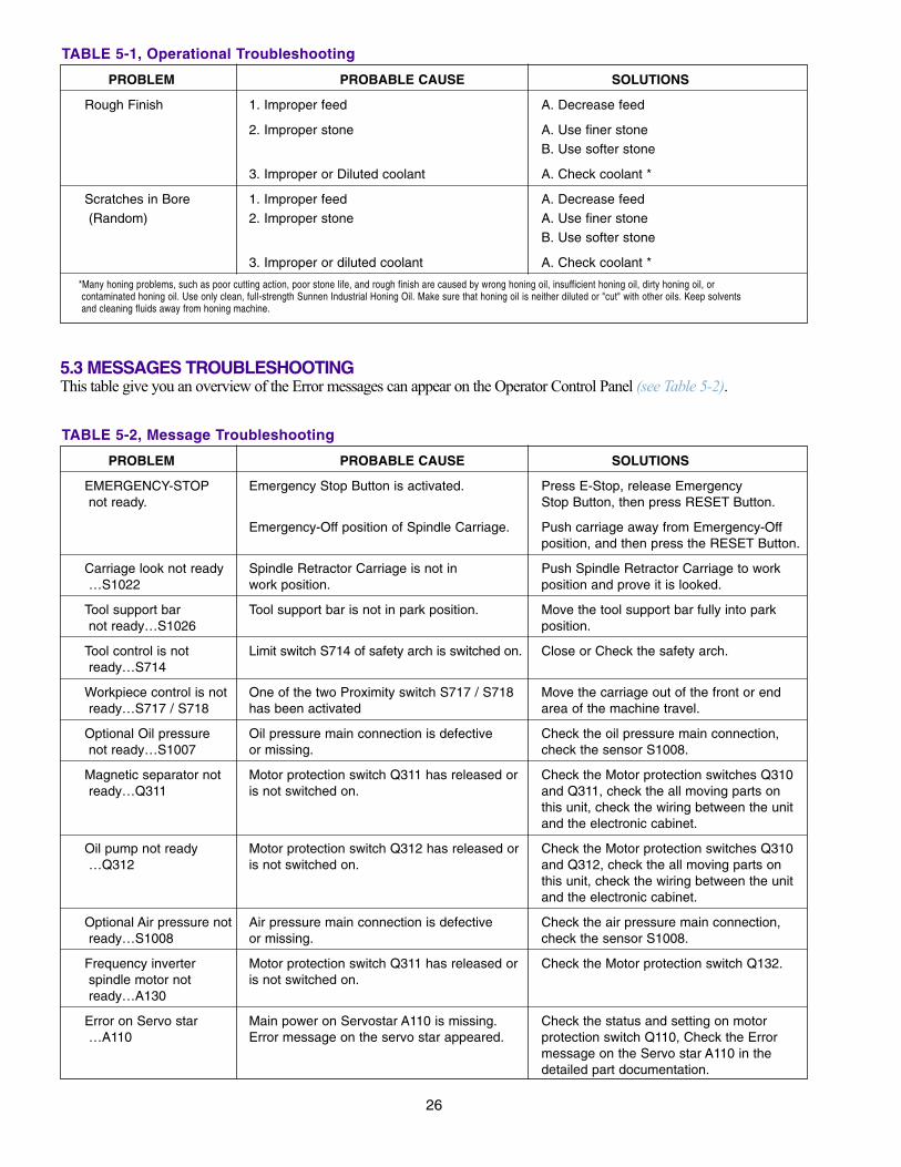
26
PROBLEM PROBABLE CAUSE SOLUTIONS
Rough Finish 1. Improper feed A. Decrease feed
2. Improper stone A. Use finer stoneB. Use softer stone
3. Improper or Diluted coolant A. Check coolant *
Scratches in Bore 1. Improper feed A. Decrease feed(Random) 2. Improper stone A. Use finer stone
B. Use softer stone
3. Improper or diluted coolant A. Check coolant *
*Many honing problems, such as poor cutting action, poor stone life, and rough finish are caused by wrong honing oil, insufficient honing oil, dirty honing oil, or contaminated honing oil. Use only clean, full-strength Sunnen Industrial Honing Oil. Make sure that honing oil is neither diluted or "cut" with other oils. Keep solvents and cleaning fluids away from honing machine.
TABLE 5-1, Operational Troubleshooting
5.3 MESSAGES TROUBLESHOOTING This table give you an overview of the Error messages can appear on the Operator Control Panel (see Table 5-2).
PROBLEM PROBABLE CAUSE SOLUTIONS
EMERGENCY-STOP Emergency Stop Button is activated. Press E-Stop, release Emergencynot ready. Stop Button, then press RESET Button.
Emergency-Off position of Spindle Carriage. Push carriage away from Emergency-Off position, and then press the RESET Button.
Carriage look not ready Spindle Retractor Carriage is not in Push Spindle Retractor Carriage to work …S1022 work position. position and prove it is looked.
Tool support bar Tool support bar is not in park position. Move the tool support bar fully into park not ready…S1026 position.
Tool control is not Limit switch S714 of safety arch is switched on. Close or Check the safety arch.ready…S714
Workpiece control is not One of the two Proximity switch S717 / S718 Move the carriage out of the front or end ready…S717 / S718 has been activated area of the machine travel.
Optional Oil pressure Oil pressure main connection is defective Check the oil pressure main connection, not ready…S1007 or missing. check the sensor S1008.
Magnetic separator not Motor protection switch Q311 has released or Check the Motor protection switches Q310 ready…Q311 is not switched on. and Q311, check the all moving parts on
this unit, check the wiring between the unit and the electronic cabinet.
Oil pump not ready Motor protection switch Q312 has released or Check the Motor protection switches Q310 …Q312 is not switched on. and Q312, check the all moving parts on
this unit, check the wiring between the unit and the electronic cabinet.
Optional Air pressure not Air pressure main connection is defective Check the air pressure main connection, ready…S1008 or missing. check the sensor S1008.
Frequency inverter Motor protection switch Q311 has released or Check the Motor protection switch Q132.spindle motor not is not switched on.ready…A130
Error on Servo star Main power on Servostar A110 is missing. Check the status and setting on motor …A110 Error message on the servo star appeared. protection switch Q110, Check the Error
message on the Servo star A110 in the detailed part documentation.
TABLE 5-2, Message Troubleshooting

5.4 GENERAL FAULT TROUBLESHOOTING This Table gives a list of General Faults (see Table 5-3).
27
PROBLEM PROBABLE CAUSE SOLUTIONS
PF401G not ready 1. Motor protection switch Q314 has released A. Check the Motor protection switches Q310 …Q314 or is not switched on. and Q314, check the all moving parts on
this unit, check the wiring between the unit and the electronic cabinet.
Light curtain not ready 1. Sensor has no power or dirty lenses. A. Check the light indication at the back on Sensor is not correct adjusted. the sensor mounted in the splash guard.
Clean the lens. Readjust the receiver exactly against the sender.
Stroke to far from 1. Carriage has been moved manually out of A. Drive the carriage manually (with the start position. operating range. AUTO mode is not Joystick) in the working range between
accessible. the two end switch blocks and press the RESET Button.
Max. honing time 1. The maximum honing time in the measure A. Press RESET Button and continue and override mode is exceeded. analyze why the time has been exceeded.
Failure on profibus 1. Profibus connection from CPU A3000 to A. Check the wiring in between the two units. connection to output Servostar A110 is not correctly connected Or Exchange the CPU or the Servostar stage. or defective. drive if no connection failure can be found.
Maximum power 1. Load on Spindle is too high A. Retract honing tool, then move to Start override. position and Start again.
2. FEED setting is too high. A. Adjust FEED setting to a lower value.
TABLE 5-2, Message Troubleshooting
PROBLEM PROBABLE CAUSE SOLUTIONS
Keys are locked 1. Control Error. A. Turn Main Power Switch OFF, then ON and then re-initialize.
EMERGENCY-STOP 1. Thermo Relays Fault (Q411, F413, F414) A. Check thermo relays (Q411, F413, F414)can not be released
2. Speed Regulator Fault. A. Check Status of the speed regulator.
Spindle Motor still run 1. The motor control unit A130 fails A. Replace the motor control unit A130.after End of program
2. IN/OUT Board A3000 defective. A. Replace the IN/OUT Board A3000
Coolant Pump and 1. The relay K2007 or K2006 fails A. Replace the Relay K2007 or K2006.Magnetic Filter is still 2. IN/OUT Board A3000 defective. A. Replace the IN/OUT Board A3000On after End of program 3. CPU circuit board damaged. A. Replace CPU circuit-board
Carriage moves in 1. Initialize Sensor S115 is defective. A. Replace Initialize Sensor S115.Manual Mode ONLY to 2. IN/OUT Board A3000 defective. A. Replace the IN/OUT Board A3000the right direction 3. CPU circuit-board damaged A. Replace CPU circuit-board
By Initialize, Carriage 1. Initialize Sensor S115 is defective A. Replace Initialize Sensor S115.moves very slowly to 2. IN/OUT Board A3000 defective. A. Replace the IN/OUT Board A3000the right 3. CPU circuit-board damaged A. Replace CPU circuit-board
TABLE 5-3, General Fault Troubleshooting

28
5.5 FEED SYSTEM TROUBLESHOOTING This Table gives a list of Faults on Feed System (see Table 5-4).
PROBLEM PROBABLE CAUSE SOLUTIONS
No Feed, but LED 1. Feed Mechanism of Extension or Tool is A. Check Pinion. Pins, Feed Screwis ON broken
2. Connection to Feed Motor is not existing A. Check Power Supply to Feed Motor
Rapid Feed or Feed in 1. Motor protection switch Q142 is off A. Reset Q142 in the electrical cabinet.Progress do not work or activated.
2. 24V DC control voltage is missing. A. Check the Motor protection switch Q411 and the fuses F413 and F414
Spindle Load Meter 1. Spindle Speed is too high A. Set spindle speed to the right reads 80% but there is value (consult Spindle Speed Chart). no Stock Removal 2. Incorrect Zero setting A. Readjust Zero setting.
Feed in Progress LED 1. Stone Glazing (Stone locks clean) A. Dress stoneis Continuously ON, but 2. Extensions or Honing Tool are defect A. Check Extension and Honing Toolthe Spindle Load Meter 3. Incorrect Zero setting. A. Readjust Zero setting.goes not up 4. Material too hard A. Use softer stone
TABLE 5-4, Feed System Troubleshooting

TABLE A-1, STOCK REMOVAL in cm3
CALCULATIONS FORMULASNOTE: These formulas are calculated when using SUNNEN MB30 Honing Oil.
APPENDIX A
STOCK REMOVAL: = Ø x Length x Stock Removal = cm3636
EXAMPLE:
100 mm x 1200 mm x 0,28 mm = 52,8 cm3636
TABLE A-2, HONING TIME in minutes (320 cm3/h)
HONING TIME: = Ø x Length x Stock Removal = min.3400
EXAMPLE:
100 mm x 1200 mm x 0,28 mm = 10 min.3400
TABLE A-3, Stock Removal for SURFACE FINISH
Required Stock Removal on Ø: = Existing Finish - Desired Finish = mm100
EXAMPLE:
0,8 Ra (N6) - 0,1 Ra (N3) = 0,007 mm100
TABLE A-4, STONE CONSUMPTION
One Set of Stones consists of 4 Sticks 0,85 cm x 0,85 cm x10.2 cm long = 29.48 cm3 in one set ofH70-A45N Stones. On the assumption of stone wear being at a ratio of 1:25 to Material Removed
= 29.48 x 25 = 737 cm3 material removed with one set of H70 Stones
Parts per Set of Stone: = 737 cm3 = PartsStock Removal
EXAMPLE:
737 cm3 = 14 Parts per Set of Stone52,7 cm3

30
APPENDIX A
TABLE A-5, CROSSHATCH ANGLE
30° = tg 15° (0,2679)
45° = tg 22,5° (0,4142)
60° = tg 30° (0,5774)
90° = tg 45° (1,0)
Example to calculate:
Bore Diameter: = 100 mm
RPM: = 175
Crosshatch Angle: = 60°
V m/min: = ??
To calculate the Crosshatch Angle consult following Formulas:
Stroke Speed V (m/min.): = Ø x 3,14 x RPM x tg (30°) = m/min1000
EXAMPLE: 100 x 3,14 x 175 x 0,5774 = 31.73 m/min1000
Spindle Speed RPM: = 1000 x V (m/min) = RPMØ x 3,14 x tg (30°)
EXAMPLE: 1000 x 30 = 165,5 RPM100 mm x 3,14 x tg 0,5774
CROSSHATCH ANGLE (60°)
CalculatingAngle (60°/2) = 30

PNEUMATIC FLOW DIAGRAM
31
APPENDIX B
FIGURE B-1, PNEUMATIC FLOW DIAGRAM (HTB)
MAX. 1 TURNOPEN
Y404
CARRIAGE RELEASE
FACTORY AIRP (in)
MIN. 6 BAR
FILTERREGULATOR
Y402(in)
TOOL SUPPORT (OPTIONAL)
Y403(in)
MOVING SUPPORT (OPTIONAL)
Y401
Y407(in)
AUTOMATIC SIZE CONTROL (OPTIONAL)
Y408(in)
R (OUT)

NOTES
32

COOLANT SYSTEM FLOW DIAGRAM
33
FIGURE C-1, Coolant System Flow Diagram
APPENDIX C
FLOWCONTROLVALVE
TRAYDRAIN
NOZZLE
COOLANTRESERVOIR
INTAKE
COOLANT
MAGNETICFILTER

34
FILTERED
With valves handles in theirhorizontal position: The coolantsystem with filter engaged -coolant passes through filters,delivering filtered coolant to themachine.
UNFILTERED
With valves handles in theirvertical position: The coolantfilters are disengaged - coolantbypasses filters, deliveringunfiltered coolant to the machine.
NOTE:
The setting of the HIGH PRESSURE RELIEF VALVE is: 45 psi (3.1 bar)
The setting of the LOW PRESSURE RELIEF VALVE is: 10 psi (0.7 bar)
FIGURE C-2, PF-401 Filter Unit
APPENDIX C
FLOWCONTROLVALVE
TRAYDRAIN
NOZZLE
HIGH PRESSURE RELIEF VALVELOWPRESSURERELIEFVALVE
COOLANTRESERVOIR
SHUTOFFVALVE
DIRECTIONALVALVE
FILTERCANISTER
INTAKE
CLEAN OIL
OPEN
DIRTY OIL
FLOWCONTROLVALVE
TRAYDRAIN
NOZZLE
HIGH PRESSURE RELIEF VALVELOWPRESSURERELIEFVALVE
SHUTOFFVALVE
DIRECTIONALVALVE
FILTERCANISTER
CLEAN OIL
CLOSED
DIRTY OIL
DIRTY OIL
DIRTY OIL
COOLANTRESERVOIR
INTAKE

Rt Rz N 1-N 10 Ra / CLA RMS GUSµm µm µm µin. µin. Knocc
0,1 - 0,3 0,17 N1 0,02 0,8 0,9 - 1,0 14
0,2 - 0,5 0,3 N2 0,04 1,6 1,8 - 1,9 13
0,3 - 0,7 0,43 0,06 2,4 2,6 - 2,9 12
0,4 - 0,8 0,52 N3 0,08 3,2 3,5 - 3,8 11
0,5 - 1,0 0,65 0,10 4,0 4,4 - 4,8
0,6 - 1,2 0,77 N4 0,12 4,8 5,3 - 5,8
0,65 - 1,4 0,86 0,14 5,6 6,2 -6,8
0,7 - 1,6 1,00 0,16 6,4 7,0 - 7,7
0,8 - 1,7 1,07 0,18 7,2 7,9 - 8,6 10
0,9 - 1,9 1,20 0,20 8,0 8,8 - 9,6
1,1 - 2,3 1,45 N5 0,25 10,0 11,0 - 12,0
1,3 - 2,7 1,70 0,30 12,0 13,2 - 14,4
1,5 - 3,0 1,95 0,35 14,0 15,4 - 16,8
1,7 - 3,4 2,20 0,40 16,0 17,6 - 19,2 9
1,9 - 3,8 2,45 N6 0,45 18,0 19,8 - 21,6
2,3 - 4,2 2,70 0,50 20,0 22,0 - 24,0
2,7 - 5,2 3,45 0,65 26,0 28,6 - 31,2 8
3,7 - 7,0 4,60 N7 0,90 36,0 39,6 - 43,2
4,5 - 8,2 5,45 1,10 44,0 48,4 - 52,8
5,2 - 9,5 6,35 1,30 52,0 57 - 62 7
6,0 - 10,0 7,10 1,50 60,0 66 - 72
7,1 - 12,5 8,45 N8 1,80 72,0 79 - 86
9,6 - 16,5 11,20 2,50 100 110 - 120 6
13,0 - 22,0 15,10 N9 3,50 140 154 - 168
17,0 - 28,0 19,40 4,50 180 198 - 216
18,0 - 30,0 20,60 5,00 200 220 - 240 5
22,0 - 35,0 24,50 6,00 240 264 - 288
25,0 - 40,0 27,90 N10 7,00 280 308 - 336
28,0 - 45,0 31,40 8,00 320 352 - 384
35
SURFACE ROUGHNESS TABLEAPPENDIX D

NOTES
36

FIXTURE HEIGHT CHARTfor ø 350-700 mm (Optional HT-350)
37
APPENDIX E
Pos. 1 Pos. 2 Pos. 3 Pos. 4 Pos. 5 Pos. 6OD
D (min.) --- 350 380 420 460 500DIAMETER
D (max.) -- 380 420 460 500 530in mm
With PRISM PLATES (60 mm)
Maximal Outside Diameter under Covers 600 mm
Pos. 1 Pos. 2 Pos. 3 Pos. 4 Pos. 5 Pos. 6OD
D (min.) --- --- 500 530 590 620DIAMETER
D (max.) --- --- 530 590 620 700in mm
Without PRISM PLATES

NOTES
38

FIXTURE HEIGHT CHARTfor ø 13-27.5 in. (Optional HT-350)
39
APPENDIX F
Pos. 1 Pos. 2 Pos. 3 Pos. 4 Pos. 5 Pos. 6OD
D (min.) --- 13 15 16.5 18 20DIAMETER
D (max.) -- 15 16.5 18 20 21in inches
With PRISM PLATES (2.36 in.)
Maximal Outside Diameter under Covers 24 in.
Pos. 1 Pos. 2 Pos. 3 Pos. 4 Pos. 5 Pos. 6OD
D (min.) --- --- 19.5 21 23 24.5DIAMETER
D (max.) --- --- 21 23 24.5 27.5in inches
Without PRISM PLATES

NOTES
40

1. Turn the Main Power Switch OFF.
2. Disconnect Honing Tool.
3. Install and fix the workpiece.
4. Turn the Main Power Switch at the electronic cabinet ON.
5. Release the E-STOP Button, close Carriage Release and move the tool support manually to park position.
6. Press and hold RESET Button until the blue indication light has turned off.
7. Initialize: Press on screen, Carriage moves in left direction to the reference point.
8. Use Joystick and press to move carriage far enough to the right until Honing Tool can be connected.
9. Reconnect Honing Tool.
10. Expand stones in workpiece bore with Manual Feed Switch. Turn to EXPAND.
11. Use Joystick and press to move Honing Tool to left end of workpiece; then add ¼ of Stone length to allow
for overstroke.
12. Set Stroke Start Position over menu by pressing on screen.
13. Adjust left SAFETY STOP manually.
14. Use Joystick and press it to move Honing Tool to right end of workpiece; then add ¼ of Stone length to
allow for overstroke.
15. Set Stroke End Position by pressing on screen.
16. Adjust Right SAFETY STOP manually.
17. Optional: Set load position, press and activate it with the this button on screen.
18. Optional: If the workpiece length is more then 5000mm we recommend to set the steady set and teach the
steady set position and activate it with the button on screen.
19. Set All Speed parameters , set the correct workpiece diameter and adjust the HAND WHEEL ON
THE SPINDLE DRIVE to the recommended value appears in the field gear step position.
20. Set Spindle Load Parameters .
21. Set Cycle Mode Parameters the Honing Time to your need.
22. Adjust Coolant Nozzle and open Flow Control Valve manually by handle.
23. Position Splash Guards.
24. Go to the menu press and set Feed Direction, Feed Delay and Feed Rate to your need.
25. Go to the menu press and to set the Coolant on or off.
26. Go back to the main screen and set the mode to AUTO .
27. Press Hardware Cycle START Button. Machine starts honing cycle.
28. Machine stop honing when Timer reaches Zero “00:00” or the Hardware Cycle STOP Button is pressed.
41
SETUP & OPERATION CHECK LISTAPPENDIX G

42
29. Retract stones, by turning Manual Feed Switch to retract.
30. Swing Tool Support manually into Load Position.
31. Push CARRIAGE RELEASE Button on screen and slide honing tool out of the bore.
32. Use the following steps to store the product setup: Go into menu SETUP, MORE SCREENS, FILES, SAVE AS,
type a product corresponding name in and reconfirm with YES.
APPENDIX E

Like any machinery, this equipment maybe dangerous if used improperly. Be sureto read and follow instructions foroperation of equipment.
NOTE: The machine is set up, the Main Power Switch is turned OFF, and the machine is supposed to start the next
cycle with the previously selected values.
IMPORTANT: Workpiece MUST maintain the previous position.
1. Disconnect Honing Tool.
2. Turn the Main Power Switch at the electronic cabinet ON.
3. Release the E-STOP Button, close Carriage Release and move the tool support manually to park position.
4. Press and hold RESET Button until the blue indication light has turned off.
5. Initialize: Press on screen, Carriage moves in left direction to the reference point
6. Use Joystick and press it to move carriage far enough to the right until Honing Tool can be connected.
7. Insert Honing Tool in workpiece bore; then reconnect Tool.
8. Lightly expand tool by turning Manual Feed Switch to EXPAND.
9. Go to the main screen and set the mode to AUTO .
10. Press Hardware Cycle START Button. Machine starts honing cycle.
43
WORK CYCLE CHECK LISTAPPENDIX H
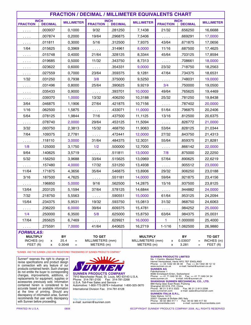
FRACTION / DECIMAL / MILLIMETER EQUIVALENTS CHARTINCH
FRACTION DECIMAL MILLIMETER
. . . . .003937 0,1000
. . . . .007874 0,2000
. . . . .011811 0,3000
1/64 .015625 0,3969
. . . . .015748 0,4000
. . . . .019685 0,5000
. . . . .023622 0,6000
. . . . .027559 0,7000
1/32 .031250 0,7938
. . . . .031496 0,8000
. . . . .035433 0,9000
. . . . .039370 1,0000
3/64 .046875 1,1906
1/16 .062500 1,5875
5/64 .078125 1,9844
. . . . .078740 2,0000
3/32 .093750 2,3813
7/64 .109375 2,7781
. . . . .118110 3,0000
1/8 .125000 3,1750
9/64 .140625 3,5719
5/32 .156250 3,9688
. . . . .157480 4,0000
11/64 .171875 4,3656
3/16 .187500 4,7625
. . . . .196850 5,0000
13/64 .203125 5,1594
7/32 .218750 5,5563
15/64 .234375 5,9531
. . . . .236220 6,0000
1/4 .250000 6,3500
17/64 .265625 6,7469
. . . . .275591 7,0000
INCHFRACTION DECIMAL MILLIMETER
9/32 .281250 7,1438
19/64 .296875 7,5406
5/16 .312500 7,9375
. . . . .314961 8,0000
21/64 .328125 8,3344
11/32 .343750 8,7313
. . . . .354331 9,0000
23/64 .359375 9,1281
3/8 .375000 9,5250
25/64 .390625 9,9219
. . . . .393701 10,0000
13/32 .406250 10,3188
27/64 .421875 10,7156
. . . . .433071 11,0000
7/16 .437500 11,1125
29/64 .453125 11,5094
15/32 .468750 11,9063
. . . . .472441 12,0000
31/64 .484375 12,3031
1/2 .500000 12,7000
. . . . .511811 13,0000
33/64 .515625 13,0969
17/32 .531250 13,4938
35/64 .546875 13,8906
. . . . .551181 14,0000
9/16 .562500 14,2875
37/64 .578125 14,6844
. . . . .590551 15,0000
19/32 .593750 15,0813
39/64 .609375 15,4781
5/8 .625000 15,8750
. . . . .629921 16,0000
41/64 .640625 16,2719
INCHFRACTION DECIMAL MILLIMETER
21/32 .656250 16,6688
. . . . .669291 17,0000
43/64 .671875 17,0656
11/16 .687500 17,4625
45/64 .703125 17,8594
. . . . .708661 18,0000
23/32 .718750 18,2563
47/64 .734375 18,6531
. . . . .748031 19,0000
3/4 .750000 19,0500
49/64 .765625 19,4469
25/32 .781250 19,8438
. . . . .787402 20,0000
51/64 .796875 20,2406
13/16 .812500 20,6375
. . . . .826772 21,0000
53/64 .828125 21,0344
27/32 .843750 21,4313
55/64 .859375 21,8281
. . . . .866142 22,0000
7/8 .875000 22,2250
57/64 .890625 22,6219
. . . . .905512 23,0000
29/32 .906250 23,0188
59/64 .921875 23,4156
15/16 .937500 23,8125
. . . . .944882 24,0000
61/64 .953125 24,2094
31/32 .968750 24,6063
. . . . .984252 25,0000
63/64 .984375 25,0031
1 1.000000 25,4000
1-1/16 1.062500 26,9880
FORMULAS:MULTIPLY BY TO GET MULTIPLY BY TO GET
INCHES (in) x 25.4 = MILLIMETERS (mm) MILLIMETERS (mm) x 0.03937 = INCHES (in)FEET (ft) x 0.3048 = METERS (m) METERS (m) x 3.281 = FEET (ft)
PRINTED IN U.S.A. 0808 ©COPYRIGHT SUNNEN® PRODUCTS COMPANY 2008, ALL RIGHTS RESERVED
SUNNEN PRODUCTS COMPANY7910 Manchester Road, St. Louis, MO 63143 U.S.A.Phone: 314-781-2100 Fax: 314-781-2268U.S.A. Toll-Free Sales and Service –Automotive: 1-800-772-2878 • Industrial: 1-800-325-3670International Division Fax: 314-781-6128
http://www.sunnen.come-mail: [email protected]
SUNNEN PRODUCTS LIMITEDNo. 1 Centro, Maxted RoadHemel Hempstead, Herts HP2 7EF ENGLANDPhone: ++ 44 1442 39 39 39 Fax: ++ 44 1442 39 12 12www.sunnen.co.uk e-mail: [email protected] AGFabrikstrasse 18586 Ennetaach-Erlen, SwitzerlandPhone: ++ 41 71 649 33 33 Fax: ++ 41 71 649 34 34www.sunnen.ch e-mail: [email protected] SUNNEN MECHANICAL CO., LTD.889 Kang Qiao East Road, PuDongShanghai 201319, P.R. ChinaPhone: 86 21 5 813 3322 Fax: 86 21 5 813 2299www.sunnensh.com e-mail: [email protected] ITALIA S.R.L.Viale Stelvio 12/1520021 Ospiate di Bollate (MI) ItalyPhone: 39 02 383 417 1 Fax: 39 02 383 417 50www.sunnenitalia.com e-mail: [email protected]
Sunnen® reserves the right to change orrevise specifications and product designin connection with any feature of ourproducts contained herein. Such changesdo not entitle the buyer to correspondingchanges, improvements, additions, orreplacements for equipment, supplies oraccessories previously sold. Informationcontained herein is considered to beaccurate based on available informationat the time of printing. Should any discrepancy of information arise, Sunnenrecommends that user verify discrepancywith Sunnen before proceeding.
“SUNNEN AND THE SUNNEN LOGO ARE REGISTERED TRADEMARKS OF SUNNEN PRODUCTS COMPANY.”