Embed Size (px)
Citation preview

N3MG(HP)(E)/N3HM(G)(E)/N3HM(G)HP
This manual has been designed to be used in conjunction with the General (UL/NSF) Installation & Service Manual.
Save the Instructions in Both Manuals for Future Reference!!These merchandisers conform to the American National Standard Institute & NSF International Health and Sanitation standard ANSI/NSF 7 - 2003.
PRINTED IN Specifications subject to REPLACES ISSUE PARTIN U.S.A. change without notice. EDITION 7/06 DATE 4/07 NO. 9037147 REV. F.1
Tyler Refrigeration * Niles, Michigan 49120
THREE DECK MEAT/DELI/CRITICAL TEMP PRODUCE AND HIGHPERFORMANCE MERCHANDISERS AND END MERCHANDISERS
Medium Temperature Self Serve Display Cases
Installation & ServiceManual
N3HMGHPYE1172
CONTENTS
N3MG(E)/N3MGHP(E)/N3HM(G)(E)/N3HM(G)HP
Page 2 April, 2007
PageSpecifications
N3MG & N3MGE Specification Sheets . . . . . . . . . . . . . . . . . . . . . . . 4N3MGHP & N3MGHPE Specification Sheets . . . . . . . . . . . . . . . . . . 7N3HM, N3HMG, N3HME & N3HMGE Specification Sheets . . . . . . 10N3HMHP & N3HMGHP Specification Sheets . . . . . . . . . . . . . . . . . 13Line Sizing Requirements . . . . . . (See General-UL/NSF I&S Manual)
Pre-Installation Responsibilities . . . . . (See General-UL/NSF I&S Manual)Installation Procedures
Carpentry Procedures . . . . . . . . . . . . . . . . . . . . . . . . . . . . . . . . . . 15Case Pull-Up Locations . . . . . . . . . . . . . . . . . . . . . . . . . . . . . . . . . 15Plumbing Procedures . . . . . . . . (See General-UL/NSF I&S Manual)Refrigeration Procedures . . . . . (See General-UL/NSF I&S Manual)Electrical Procedures . . . . . . . . . . . . . . . . . . . . . . . . . . . . . . . . . . . 15Electrical Considerations . . . . . . . . . . . . . . . . . . . . . . . . . . . . . . . . . 15Defrost Information . . . . . . . . . . . . . . . . . . . . . . . . . . . . . . . . . . . . 16Defrost Control Chart . . . . . . . . . . . . . . . . . . . . . . . . . . . . . . . . . . . 16Installation Procedure Check Lists (See Gen.-UL/NSF I&S Manual)
Wiring Diagrams . . . . . . . . . . . . . . . . . . . . . . . . . . . . . . . . . . . . . . . . . . . 16N3MG, N3HM & N3HMG Domestic & Export (50Hz) Case Circuits . . . . . . . . . . . . . . . . . . 17N3HMHP & N3HMGHP Domestic & Export (50Hz) Case Circuits . . . . . . . . . . . . . . . . . . 23N3MGE, N3MGHPE, N3HME, N3HMGEDomestic & Export (50Hz) Case Circuits . . . . . . . . . . . . . . . . . . 25
Cleaning and SanitationComponent Removal and Installation Instructions for Cleaning 27Shelves and Shelf Brackets . . . . . . . . . . . . . . . . . . . . . . . . . . . . . . . 27Bottom Trays . . . . . . . . . . . . . . . . . . . . . . . . . . . . . . . . . . . . . . . . . . 27Front Air Ducts . . . . . . . . . . . . . . . . . . . . . . . . . . . . . . . . . . . . . . . . 27Rear Duct Panels . . . . . . . . . . . . . . . . . . . . . . . . . . . . . . . . . . . . . . 27Discharge Air Honeycomb . . . . . . . . . . . . . . . . . . . . . . . . . . . . . . . 27Lower Cladding (N3MG/N3MGHP) . . . . . . . . . . . . . . . . . . . . . . . . 27Upper Cladding (N3MG/N3MGHP) . . . . . . . . . . . . . . . . . . . . . . . . 27Front Cladding (N3HM(G)/N3HM(G)HP) . . . . . . . . . . . . . . . . . . . . . 28Cleaning Instructions . . . . . . . . . . . . . . . . . . . . . . . . . . . . . . . . . . . 28Stainless Steel Cleaning Methods . . . . . . . . . . . . . . . . . . . . . . . . 28
Installation & Service ManualN3MG(E)/N3MGHP(E)/
N3HM(G)(E)/N3HM(G)HP
July, 2006 Page 3
PageGeneral Information
NSF Product Thermometer . . . . . . . . . . . . . . . . . . . . . . . . . . . . . 30Radiant Heat Information . . . . . . . . . . . . . . . . . . . . . . . . . . . . . . . 30Radiant Heat Measurement . . . . . . . . . . . . . . . . . . . . . . . . . . . . . . . 31Display Practices . . . . . . . . . . . . . . . . . . . . . . . . . . . . . . . . . . . . . . . 31
Service InstructionsPreventive Maintenance . . . . . . (See General-UL/NSF I&S Manual)Light Servicing . . . . . . . . . . . . . . . . . . . . . . . . . . . . . . . . . . . . . . . . 31Ballast and Lighting Locations . . . . . . . . . . . . . . . . . . . . . . . . . . . . . 31Compact Light Replacement (All Crown End Cases) . . . . . . . . . . . 32Defrost Heater Replacement . . . . . . . . . . . . . . . . . . . . . . . . . . . . . .32Fan Blade and Motor Replacement (See Gen.-UL/NSF I&S Manual)Color Band and Bumper Replacement (See Gen.-UL/NSF I&S Man.)Anti-Sweat Replacement . . . . . . . . . . . . . . . . . . . . . . . . . . . . . . . . 33Top Light Channel Anti-Sweat Replacement . . . . . . . . . . . . . . . . . . 33Top Front Glass Anti-Sweat Replacement (N3MG/N3HMG) . . . . . . 33Front Glass Replacement (N3MG(HP)/N3HMG(HP)) . . . . . . . . . 34Removing Metal Edge Trim . . . . . . . . . . . . . . . . . . . . . . . . . . . . . . .34
Parts InformationOperational Parts List . . . . . . . . . . . . . . . . . . . . . . . . . . . . . . . . . . 35Cladding and Trim Parts Lists . . . . . . . . . . . . . . . . . . . . . . . . . . . . 36
Revision Log . . . . . . . . . . . . . . . . . . . . . . . . . . . . . . . . . . . . . . . . .42TYLER Warranty . . . . . . . . . . . . . . . . . (See General-UL/NSF I&S Manual)
The following Medium Temperature, Low Back and High Back, Three Deck Meat/Deli andHigh Performance Merchandiser and End Merchandiser models are covered in this manual:
MODEL DESCRIPTION
N3MG 4’, 6’, 8’ & 12’ GLASS FRONT THREE DECK MEAT/DELI MERCHANDISERS
N3MGE GLASS FRONT CROWN END MERCHANDISER
N3MGHP 6’, 8’ & 12’ GLASS FRONT THREE DECK HIGH PERFORMANCE MERCHANDISERS
N3MGHPE GLASS FRONT HIGH PERFORMANCE CROWN END MERCHANDISER
N3HM 6’, 8’ & 12’ HIGH BACK SOLID FRONT THREE DECK MEAT/DELI MERCHANDISERS
N3HME HIGH BACK SOLID FRONT CROWN END MERCHANDISER
N3HMG 6’, 8’ & 12’ HIGH BACK GLASS FRONT THREE DECK MEAT/DELI MERCHANDISERS
N3HMGE HIGH BACK GLASS FRONT CROWN END MERCHANDISER
N3HMHP 6’, 8’ & 12’ HIGH BACK SOLID FRONT THREE DECK HIGH PERFORMANCE MERCHANDISERS
N3HMGHP 6’, 8’ & 12’ HIGH BACK GLASS FRONT THREE DECK HIGH PERFORMANCE MERCHANDISERS

N3MG(E)/N3MGHP(E)/N3HM(G)(E)/N3HM(G)HP
Page 4 April, 2008
SPECIFICATIONSN3MG Three Deck Meat/Deli/Critical Temp Produce MerchandisersN3MGE Glass Front Meat/Deli/Critical Temp Prod Crown End Merchandiser

Installation & Service ManualN3MG(E)/N3MGHP(E)/
N3HM(G)(E)/N3HM(G)HP
April, 2008 Page 5

N3MG(E)/N3MGHP(E)/N3HM(G)(E)/N3HM(G)HP
Page 6 April, 2008

Installation & Service ManualN3MG(E)/N3MGHP(E)/
N3HM(G)(E)/N3HM(G)HP
April, 2008 Page 7
N3MGHP Glass Front Three Deck High Performance MerchandisersN3MGHPE Glass Front High Performance Crown End Merchandiser

N3MG(E)/N3MGHP(E)/N3HM(G)(E)/N3HM(G)HP
Page 8 April, 2008

Installation & Service ManualN3MG(E)/N3MGHP(E)/
N3HM(G)(E)/N3HM(G)HP
April, 2008 Page 9
N3MG(E)/N3MGHP(E)/N3HM(G)(E)/N3HM(G)HP
Page 10 April, 2008
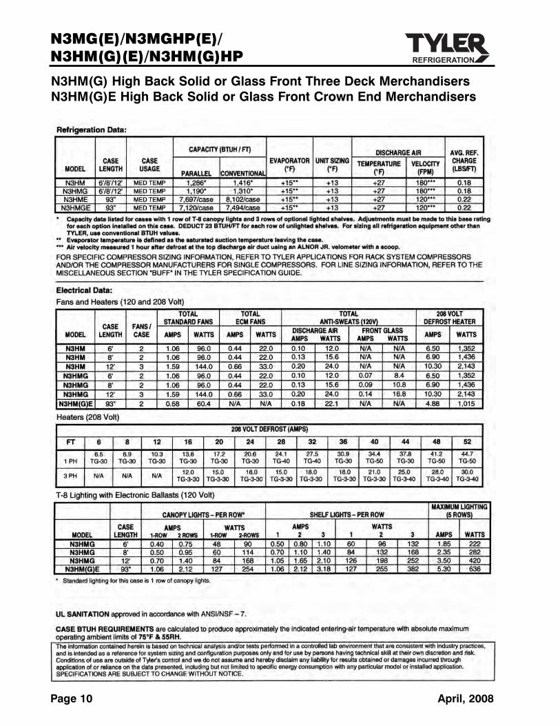
N3HM(G) High Back Solid or Glass Front Three Deck MerchandisersN3HM(G)E High Back Solid or Glass Front Crown End Merchandisers

Installation & Service ManualN3MG(E)/N3MGHP(E)/
N3HM(G)(E)/N3HM(G)HP
April, 2008 Page 11

N3MG(E)/N3MGHP(E)/N3HM(G)(E)/N3HM(G)HP
Page 12 April, 2008

Installation & Service ManualN3MG(E)/N3MGHP(E)/
N3HM(G)(E)/N3HM(G)HP
April, 2008 Page 13
N3HM(G)HP High Back Solid or Glass Front Three Deck High Performance Merchandisers

N3MG(E)/N3MGHP(E)/N3HM(G)(E)/N3HM(G)HP
Page 14 April, 2008

Installation & Service ManualN3MG(E)/N3MGHP(E)/
N3HM(G)(E)/N3HM(G)HP
April, 2007 Page 15
INSTALLATION PROCEDURESCarpentry ProceduresCase Line-Up
NOTESee the “General-UL/NSF I&S Manual” forthe proper case line-up procedures.
Case Pull-Up Locations
All standard case models have four pull-ups ateach end of the case. Pull-ups A, B, C and Dare located as shown and should be installedand tightend starting with A and finishing withD. The crown end case models have eight onthe rear of the case. These pull-ups will line upwith the pull-ups on the corresponding back-to-back standard cases.
See “General-UL/NSF I&S Manual” for line-up assembly instructions.
Bottom TraysAll bottom trays should be installed with thelips down. This assures proper case operationand sanitary practices.
Electrical Procedures
Electrical Considerations
CAUTIONMake sure all electrical connections atcomponents and terminal blocks are tight.This prevents burning of electrical termi-nals and/or premature component failure.
NOTEThe N3MG(HP) and N3HM(G)(HP) raceway houses the electrical wiring, componentsand terminal blocks in the lower front ofthe case.
Case Fan Circuit
This circuit is to be supplied by an uninter-rupted, protected 120V circuit. The case fancircuit is not cycled, except when equippedfor gas defrost. On gas defrost cases the fancircuit is controlled by a 50/40 klixon.
NOTEWith gas defrost, the fans will not startuntil the coil temperature reaches 40°F atthe fan delay thermostat.
Fluorescent Lamp Circuit
Straight case lighting is supplied by T-8 lampswith electronic ballast. Crown end case light-ing is supplied by folded compact lamps withelectronic ballasts. Both are controlled by alight switch in each case. The standard light-ing is 1-row of T-8 canopy lights in straightcases and a single folded compact lamp forcrown end top light. All case models alsooffers up to 3 rows of optional shelf lighting.
Anti-Sweat Heater Circuit
N3HM & N3HMHP cases have one anti-sweatheater in the top light assembly. N3MG(HP)and N3HMG(HP) cases have two anti-sweatheaters. One in the top light assembly andone in the front glass trim rail. All anti-sweatheaters are wired directly to the main powersupply so they can operate at all times.
N3MG/N3MGHP
N3HM/N3HMG/N3HMHP/N3HMGHP
N3MGE/N3MGHPE/N3HME/N3HMGE(Not Shown)

N3MG(E)/N3MGHP(E)/N3HM(G)(E)/N3HM(G)HP
Page 16 April, 2007
Defrost Information
See “General-UL/NSF I&S Manual” for oper-ational descriptions for each type of defrostcontrol.
Defrost Control Chart
N3MG/N3MGE Defrost Option Settings
DefrostDefrost Defrosts Duration Term.Type Per Day (Min) Temp.Off Time 6 28 ----Electric 6 36 50°FGas 6 12-15 55°F
N3MGHP/N3MGHPE Defrost Option Settings
DefrostDefrost Defrosts Duration Term.Type Per Day (Min) Temp.Off Time 4 32* ----
N3HM(G) Defrost Option Settings
DefrostDefrost Defrosts Duration Term.Type Per Day (Min) Temp.Off Time 6 22 ----Electric 6 36 50°FGas 6 12-15 55°F
N3HME/N3HMGE Defrost Option Settings
DefrostDefrost Defrosts Duration Term.Type Per Day (Min) Temp.Off Time 6 26* ----
N3HMHP/N3HMGHP Defrost Option Settings
DefrostDefrost Defrosts Duration Term.Type Per Day (Min) Temp.Off Time 6 28* ----
*See specification pages in this manual forpump down adjustment variations.
E = Electric Defrost TerminationG = Gas Defrost (Fan Delay)F/S = Electric Defrost Failsafe (Opt.)
All klixons are located on the right end of theevaporator coil. The diagram shows the location for each defrost type for the standardcases that use a klixons.
N3MGHP, N3HM(G)HP and N3MGHPEcases do not have any klixons.
NOTEThe termination klixon for gas defrost islocated at the bypass check valve at theleft end of the evaporator coil.
CAUTIONIf electronic sensors are used in place ofthe klixons, the sensors must be located inthe same location as the klixons for thatdefrost type. Any other locations willeffect the refrigeration efficiency of thecase.
WIRING DIAGRAMSELECTRICIAN NOTE - OVERCURRENT
PROTECTION120V circuits should be protected by 15 or 20 Ampdevices per the requirements noted on the cabinetnameplate or the National Electrical Code, CanadianElectrical Code - Part 1, Section 28. 208V defrostcircuits employ No. 12 AWG field wire leads for fieldconnections. On remote cases intended for end toend line-ups, bonding for ground may rely upon thepull-up bolts.
The following wiring diagrams on pages 17 thru 24 will cover the N3MG, N3MGHP,N3HM(G), N3HM(G)HP, N3MGE, N3MGHPE,N3HME & N3HMGE case circuits including alldefrost and lighting wiring circuits.
N3MG/N3HM(G)
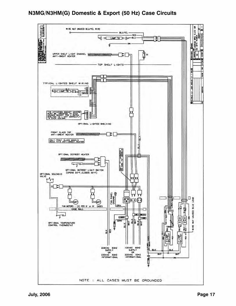
July, 2006 Page 17
N3MG/N3HM(G) Domestic & Export (50 Hz) Case Circuits
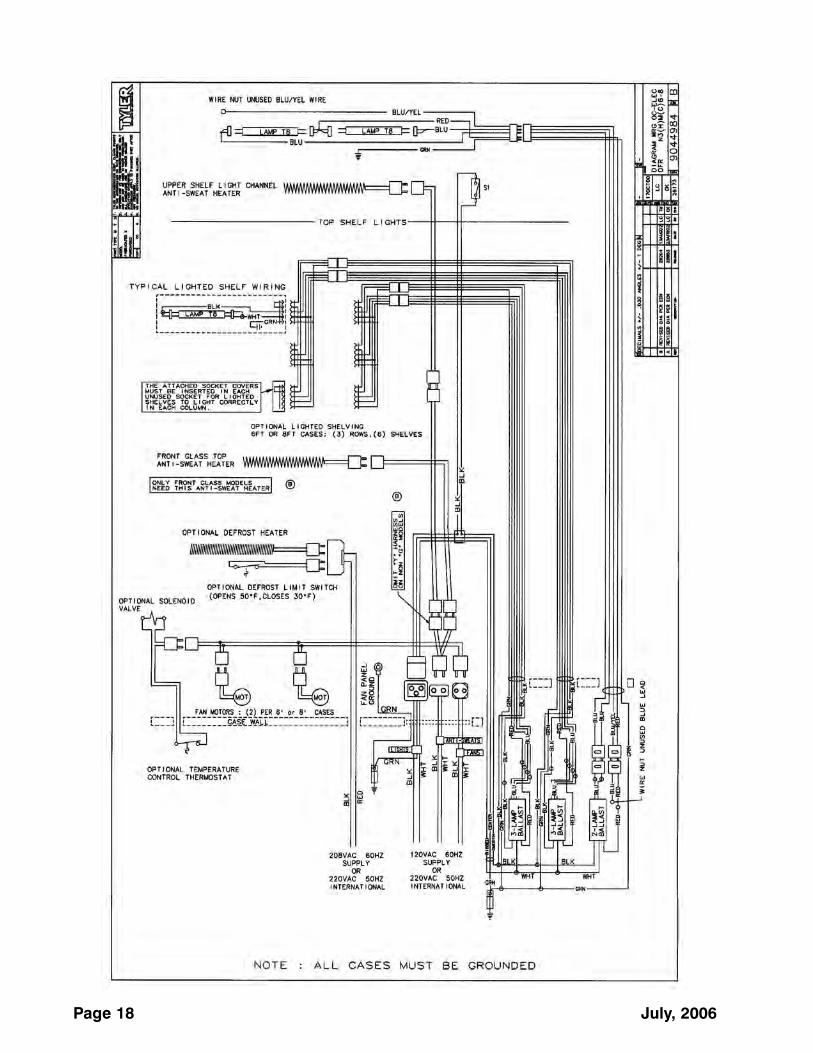
Page 18 July, 2006

July, 2006 Page 19

Page 20 July, 2006

July, 2006 Page 21

Page 22 July, 2006
N3MGHP Domestic & Export (50 Hz) Case Circuits (12' case)

N3HMGHP Domestic & Export (50 Hz) Case Circuits (6' & 8' caes)
July, 2006 Page 23

N3HMGHP Domestic & Export (50 Hz) Case Circuits (12' case)
Page 24 July, 2006

N3MGE/N3MGHPE Domestic & Export (50 Hz) Case Circuits
July, 2006 Page 25

Page 26 April, 2007
N3HME/N3HMGE Domestic & Export (50 Hz) Case Circuits

Installation & Service ManualN3MG(E)/N3MGHP(E)/
N3HM(G)(E)/N3HM(G)HP
CLEANING AND SANITATION
Component Removal and Installation Instructions forCleaningShelves and Shelf Brackets 1. Remove product from shelves.
2. If shelf has a light, unplug the light cordfrom the socket in the rear duct panel.Completely insert socket cover in the lightsocket to protect the receptacle.
3. Push shelves back and then lift up andout to remove them from the shelf brackets.
4. Remove shelf brackets from slots in rearuprights.
5. After cleaning, replace in reverse order.
Bottom Trays1. Remove product from bottom of case.
2. Grasp and lift out each of the bottom traysfrom the case interior.
3. After cleaning, replace in reverse order.
Front Air Ducts1. Remove lower trays, see this page.
2. Lift out front air duct sections.
3. After cleaning, replace in reverse order.
Rear Duct Panels (w/o Shelf Light Sockets)1. Remove shelves and bottom trays, see
above.
2. Remove mounting screws and rear ductpanels from case.
3. After cleaning, replace and secure rearduct panels in reverse order.
(with Shelf Light Sockets)1. Remove shelves and bottom trays, see
above.
2. Remove mounting screws from rear ductpanel.
3. Slowly lift out rear duct panel until theshelf harness connector near the top ofthe panel can be accessed.
4. Disconnect shelf harness connector andcomplete removing the rear duct panel.
WARNINGRear duct panels with electrical receptaclescan be cleaned without removing the electrical receptacles. Do not get moistureon electrical wires when cleaning under this cover. Moisture on wires could causepremature product failure and/or personalinjury or death from electrical shock.
5. After cleaning, reconnect the shelf harness connector and replace and secure rear duct panels in reverse order.
Discharge Air Honeycomb1. Loosen screws securing rear retainer
plate.
NOTENote position of the honeycomb grid duringremoval so it can be reinstalled the sameway.
2. Slide rear retainer plate back until the honeycomb grid sections can be removedfrom the top duct.
CAUTION
Improper installation of the honeycomb gridsection could result in improper air flowand/or poor refrigeration.
3. After cleaning, replace honeycomb gridsections as they were removed and securewith the rear retainer plate and screws.
Lower Cladding (N3MG/N3MGHP)1. Remove kickplate from kickplate supports.
(See General-UL/NSF I&S Manual.)
2. Remove mounting screws from top andbottom of lower cladding and removelower cladding.
3. After cleaning, replace in reverse order.
Upper Cladding (N3MG/N3MGHP)1. Remove lower cladding, see above.
2. Remove color band, bumper and bumperretainer from case. (See General-UL/NSFI&S Manual.)
July, 2006 Page 27

N3MG(E)/N3MGHP(E)/N3HM(G)(E)/N3HM(G)HP
Page 28 April, 2007
3. Remove mounting screws from top andbottom of upper cladding and removeupper cladding.
4. After cleaning, replace upper claddingand remaining components in reverseorder.
Front Cladding(N3HM(HP)/N3HMG(HP))1. Remove mounting screws from top of
front cladding under the top bumper andpull bottom of front cladding out anddown to remove the front cladding.
2. After cleaning, replace front cladding bysliding the top behind the bumper retainerand placing the bottom lip on the front ofthe raceway. Secure the front claddingwith the mounting screws.
Cleaning InstructionsCAUTION
• When cleaning this case, try not to intro-duce water into the case faster than it can be carried away by the waste outlet.
• Liquid chlorine bleach is corrosive tometals. The use of bleach or productscontaining bleach will damage metal sur-faces and void the case warranty.
• Sanitize the case with QuaternaryAmmonium Solutions (ex: KAYQUAT II, J-512 Sanitizer, SANIQUAT 512, etc...)approved per 21CFR 178.1010, followedby adequate draining and air drying.These solutions may be obtained fromKay Chemical Co., Johnson WaxProfessional, Coastwide Laboratories,etc....
• Always use a soft cloth or sponge withmild detergent and water to clean anyglass. Never use abrasives or scouringpads to clean glass. They can scratchand/or damage the glass.
WARNINGTYLER Refrigeration does not recommendthe use of high pressure cleaning equipmenton display cases!! High pressure cleanerscan penetrate and/or damage joint seals.Damaged seals allow water leaks and/or airleaks that can cause poor case refrigeration.
See “General (UL/NSF) I&S Manual” for casecleaning instructions.
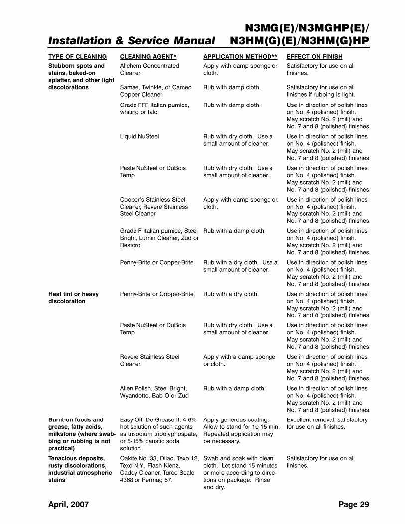
Stainless Steel Cleaning MethodsThe cleaning data in the following stainless steel cleaning chart was supplied by AISI. The information was supplied byPrime Metals Division, Alumax Aluminum Corporation.
TYPE OF CLEANING CLEANING AGENT* APPLICATION METHOD** EFFECT ON FINISH
Routine cleaning Soap, ammonia or deter- Sponge with cloth, then Satisfactory for use on allgent and water. rinse with clear water and finishes.
wipe dry.
Smears and finger- Arcal 20, Lac-O-Nu, Lumin Rub with cloth as directed Satisfactory for use on allprints Wash O’Cedar Cream on the package. finishes. Provides barrier film
Polish, Stainless Shine
Installation & Service ManualN3MG(E)/N3MGHP(E)/
N3HM(G)(E)/N3HM(G)HP
Page 29April, 2007
TYPE OF CLEANING CLEANING AGENT* APPLICATION METHOD** EFFECT ON FINISH
Stubborn spots and Allchem Concentrated Apply with damp sponge or Satisfactory for use on allstains, baked-on Cleaner cloth. finishes.splatter, and other lightdiscolorations Samae, Twinkle, or Cameo Rub with damp cloth. Satisfactory for use on all
Copper Cleaner finishes if rubbing is light.
Grade FFF Italian pumice, Rub with damp cloth. Use in direction of polish lines whiting or talc on No. 4 (polished) finish.
May scratch No. 2 (mill) and No. 7 and 8 (polished) finishes.
Liquid NuSteel Rub with dry cloth. Use a Use in direction of polish lines small amount of cleaner. on No. 4 (polished) finish.
May scratch No. 2 (mill) and No. 7 and 8 (polished) finishes.
Paste NuSteel or DuBois Rub with dry cloth. Use a Use in direction of polish lines Temp small amount of cleaner. on No. 4 (polished) finish.
May scratch No. 2 (mill) and No. 7 and 8 (polished) finishes.
Cooper’s Stainless Steel Apply with damp sponge or. Use in direction of polish lines Cleaner, Revere Stainless cloth. on No. 4 (polished) finish.Steel Cleaner May scratch No. 2 (mill) and
No. 7 and 8 (polished) finishes.
Grade F Italian pumice, Steel Rub with a damp cloth. Use in direction of polish lines Bright, Lumin Cleaner, Zud or on No. 4 (polished) finish.Restoro May scratch No. 2 (mill) and
No. 7 and 8 (polished) finishes.
Penny-Brite or Copper-Brite Rub with a dry cloth. Use a Use in direction of polish lines small amount of cleaner. on No. 4 (polished) finish.
May scratch No. 2 (mill) and No. 7 and 8 (polished) finishes.
Heat tint or heavy Penny-Brite or Copper-Brite Rub with a dry cloth. Use in direction of polish lines discoloration on No. 4 (polished) finish.
May scratch No. 2 (mill) and No. 7 and 8 (polished) finishes.
Paste NuSteel or DuBois Rub with dry cloth. Use a Use in direction of polish lines Temp small amount of cleaner. on No. 4 (polished) finish.
May scratch No. 2 (mill) and No. 7 and 8 (polished) finishes.
Revere Stainless Steel Apply with a damp sponge Use in direction of polish lines Cleaner or cloth. on No. 4 (polished) finish.
May scratch No. 2 (mill) and No. 7 and 8 (polished) finishes.
Allen Polish, Steel Bright, Rub with a damp cloth. Use in direction of polish lines Wyandotte, Bab-O or Zud on No. 4 (polished) finish.
May scratch No. 2 (mill) and No. 7 and 8 (polished) finishes.
Burnt-on foods and Easy-Off, De-Grease-It, 4-6% Apply generous coating. Excellent removal, satisfactorygrease, fatty acids, hot solution of such agents Allow to stand for 10-15 min. for use on all finishes.milkstone (where swab- as trisodium tripolyphospate, Repeated application may bing or rubbing is not or 5-15% caustic soda be necessary.practical) solution
Tenacious deposits, Oakite No. 33, Dilac, Texo 12, Swab and soak with clean Satisfactory for use on allrusty discolorations, Texo N.Y., Flash-Klenz, cloth. Let stand 15 minutes finishes.industrial atmospheric Caddy Cleaner, Turco Scale or more according to direc-stains 4368 or Permag 57. tions on package. Rinse
and dry.

N3MG(E)/N3MGHP(E)/N3HM(G)(E)/N3HM(G)HP
Page 30 April, 2007
Radiant Heat Information
A wide temperature range is shown for eachtype of lighting. This data does not show allsituations. Many situations will have higherpackage warm-up figures than indicated. It isgenerally known that the temperature of dis-played meat in refrigerated cases will runhigher than the circulated air temperature ofthe cases. A dial thermometer stuck into thecenter of a piece of meat compared with one
GENERAL INFORMATIONNSF Product ThermometerInstallation1. Unwrap the thermometer and bracket
assembly shipped loose with the case.
2. Position bracket in front left corner of theleft-most bottom tray. Making sure thebracket is flush with the left edge, use thebracket holes as a template for where todrill the holes.
3. Drill two .196” holes in the bottom tray.
NOTEFor ease of installation, position the washers and capnuts on the top side of the bracket and bottom tray.
4. Mount the bracket to the bottom tray withtwo screws, washers and capnuts.
TYPE OF CLEANING CLEANING AGENT* APPLICATION METHOD** EFFECT ON FINISH
Hard water spots Vinegar Swab or wipe with a cloth. Satisfactory for use on alland scale Rinse with water and dry. finishes.
5% oxalic acid, 5% sulamic Swab or soak with a cloth. Satisfactory for use on allacid, 5-10% phospheric acid, Let stand 10-15 minutes. finshes. Effective on tenaciousor Dilac, Oakite No. 33, Always follow with neutralizer deposites or where scale has Texo 12 or Texo N.Y. rinse, and dry. built up.
Grease and oil Organic solvents such as Rub with a cloth. Organic Satisfactory for use on allcarbon tetrachloride, tri- solvents may be flammable finishes.chlorethylene, acetone, kero- and/or toxic. Observe all sene, gasoline, benzene, precautions against fire. alcohol and chlorethane n.u. Do not smoke while vapors
are present. Be sure area is well ventilated.
* Use of proprietary names is intended only to indicate a type of cleaner, and does not constitute an endorsement, nor is omission of any proprietary cleanser to imply its inadequacy. It should be emphasized that all products should be used in strict accordance with instructions on package.
** In all applications a sponge or fibrous brush or pad are recommended. DO NOT use of ordinary steel wool, steel brushes,chlorine bleach or products containing bleach for cleaning or sanitizing stainless steel.
Installation & Service ManualN3MG(E)/N3MGHP(E)/
N3HM(G)(E)/N3HM(G)HP
Page 31April, 2007
in the air stream quickly confirms this fact.Another fact is that the surface temperature ofthe meat will be higher than the center temperature due to radiant heat. TYLER’songoing research identifies sources of radiantheat and accurately measures and records it.These charts were developed from the information gathered during this research.Two major sources of radiant heat are fromdisplay lights and ceiling surfaces. Additionalheat sources come from bad display practices which either overload the case withproduct or allow voids in the product display.Poor display practices impair the efficiency ofthe refrigeration, adding to the surface temperature of the meat. Bacteria and moldsgrow when surface temperatures rise above45°F. This prematurely discolors displayedmeats and causes unnecessary meat department losses.
Radiant Heat Measurement
Place two accurate dial thermometers side byside in a case. Cover one of the thermometerstems with black friction tape. The tempera-ture difference is the approximate amount ofradiant heat. A change in display lighting ora reduction of high ceiling temperatures (over 80°F) could reduce the radiant heat inthe case.
Display Practices
Encourage butchersto maintain all meatbelow the case loadlines and to eliminateproduct voids. Casescreens could be covered in some instancesto keep the refrigerated air over the display.
CAUTION
The quality damage done to meat productsby high temperatures and/or contaminationduring delivery, cooler storage, cutting andwrapping cannot be repaired by placingthe products into properly operating dis-play cases.
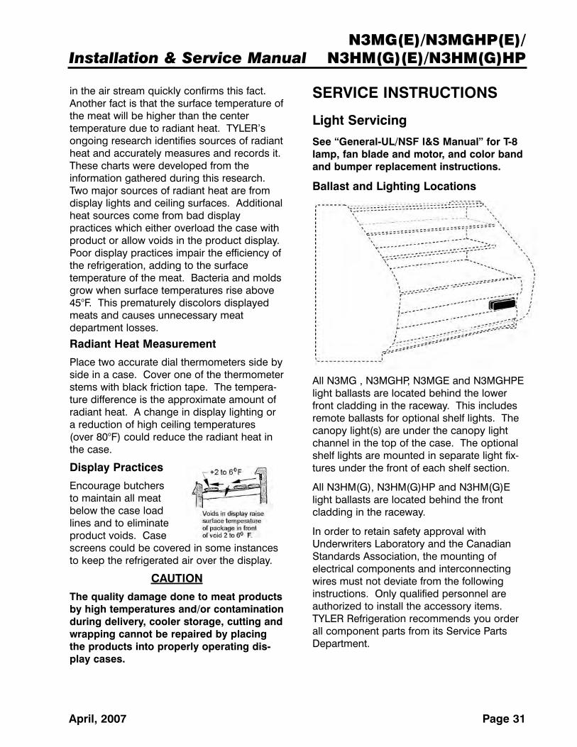
SERVICE INSTRUCTIONS
Light Servicing
See “General-UL/NSF I&S Manual” for T-8lamp, fan blade and motor, and color bandand bumper replacement instructions.
Ballast and Lighting Locations
All N3MG , N3MGHP, N3MGE and N3MGHPElight ballasts are located behind the lowerfront cladding in the raceway. This includesremote ballasts for optional shelf lights. Thecanopy light(s) are under the canopy lightchannel in the top of the case. The optionalshelf lights are mounted in separate light fix-tures under the front of each shelf section.
All N3HM(G), N3HM(G)HP and N3HM(G)Elight ballasts are located behind the frontcladding in the raceway.
In order to retain safety approval withUnderwriters Laboratory and the CanadianStandards Association, the mounting of electrical components and interconnectingwires must not deviate from the followinginstructions. Only qualified personnel areauthorized to install the accessory items.TYLER Refrigeration recommends you orderall component parts from its Service PartsDepartment.

N3MG(E)/N3MGHP(E)/N3HM(G)(E)/N3HM(G)HP
Page 32 April, 2007
Defrost Heater Replacement(N3MG/N3HM(G))
WARNINGAlways shut off electricity to case beforereplacing a defrost heater. Automaticcycling of fans or electrical power to wireends could cause personal injury and/ordeath.
1. Remove bottom trays (1) from case (2).
2. Unclip and lift up fan plenum (3).
3. Disconnect and remove defrost heater (4)from mounting clips (5) and case (2).
4. Install new defrost heater (4) in reverseorder.
5. Restore electrical power to case.
Compact Light Replacement(N3MGE/N3MGHPE/N3HM(G)E)
WARNING• Fluorescent lamps contain mercury. Do
not put lamps in trash. Recycle or dis-pose the mercury as a hazardous waste.
• Shut off light switch before changing alamp. 600V lighting system and/or bal-last surges can burn out adjacent lampsand/or cause personal injury or death.
1. Gently pull down on left end of compactlamp (1) and lampshield (2) until the lampreleases from the clips (3).
2. Unplug compact lamp (1) from receptacle(4) and remove lamp (1) and lampshield(2) from case.
3. Insert new lamp (1) in lampshield (2).Make sure cut slot in lampshield is ontop.
4. Plug new lamp (1) into receptacle (2),then secure lamp (1) and lampshield (2)in place by gently snapping assembly intothe clips (3).
5. Turn on the light switch.
Installation & Service ManualN3MG(E)/N3MGHP(E)/
N3HM(G)(E)/N3HM(G)HP
Page 33July, 2006
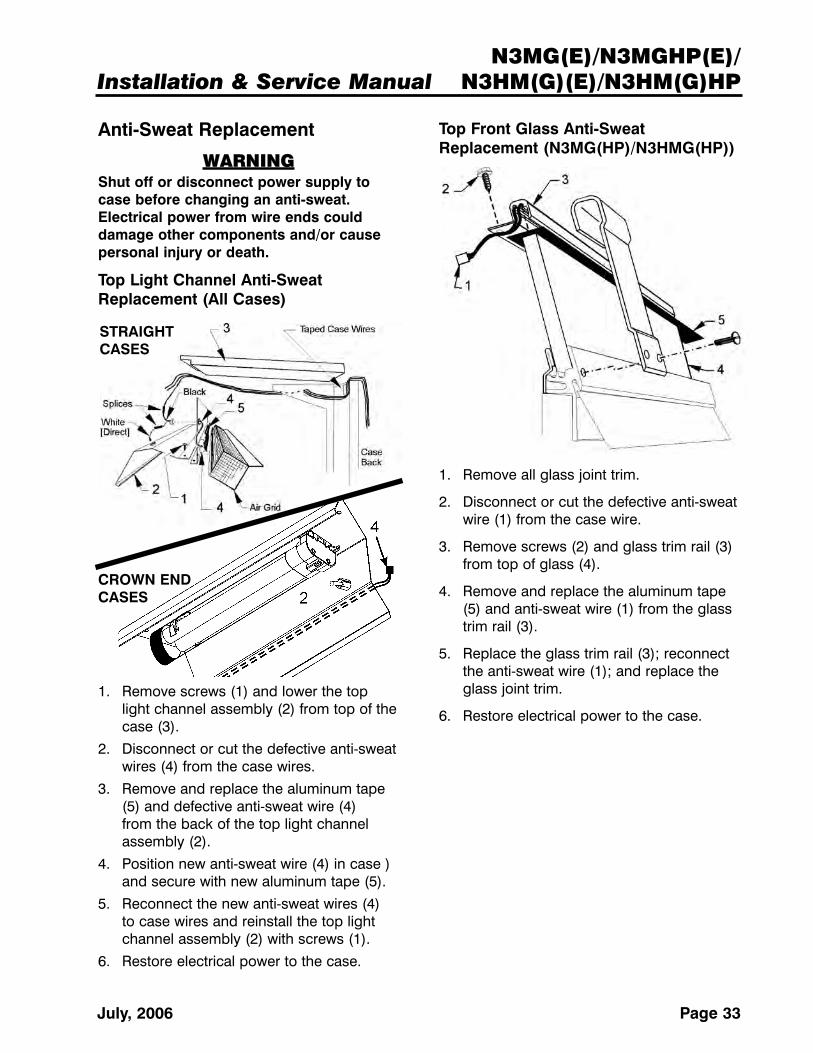
Top Front Glass Anti-SweatReplacement (N3MG(HP)/N3HMG(HP))
1. Remove all glass joint trim.
2. Disconnect or cut the defective anti-sweatwire (1) from the case wire.
3. Remove screws (2) and glass trim rail (3)from top of glass (4).
4. Remove and replace the aluminum tape(5) and anti-sweat wire (1) from the glasstrim rail (3).
5. Replace the glass trim rail (3); reconnectthe anti-sweat wire (1); and replace theglass joint trim.
6. Restore electrical power to the case.
Anti-Sweat Replacement
WARNINGShut off or disconnect power supply tocase before changing an anti-sweat.Electrical power from wire ends coulddamage other components and/or causepersonal injury or death.
Top Light Channel Anti-SweatReplacement (All Cases)
1. Remove screws (1) and lower the toplight channel assembly (2) from top of thecase (3).
2. Disconnect or cut the defective anti-sweatwires (4) from the case wires.
3. Remove and replace the aluminum tape(5) and defective anti-sweat wire (4) from the back of the top light channelassembly (2).
4. Position new anti-sweat wire (4) in case )and secure with new aluminum tape (5).
5. Reconnect the new anti-sweat wires (4) to case wires and reinstall the top lightchannel assembly (2) with screws (1).
6. Restore electrical power to the case.
STRAIGHTCASES
CROWN ENDCASES

N3MG(E)/N3MGHP(E)/N3HM(G)(E)/N3HM(G)HP
Page 34 April, 2007
Front Glass Replacement(N3MG(HP)/N3HMG(HP))
1. Unplug glass anti-sweat wire (1).
2. Remove two screw (2) and glass joint trim (3) from both joints of the brokenglass (4).
3. Remove screws (5) and glass trim rail (6)from top of glass (4).
4. Loosen rear retainer (7) and remove broken glass (4) from glass retainerassembly (8).
5. Apply sealant tape (9) to top and bottomedge of new glass (4).
6. Position new glass (4) in glass retainerassembly (8) and secure by tighteningrear retainer (7).
NOTEInspect the anti-sweat wire in glass trimrail. If wire is damaged or broken, replaceit before replacing the trim rail.
7. Install glass trim rail (6) with screws (5)over top edge of new glass (4).
8. Install glass joint trim (3) with screw (2)over the joint areas of glass (4).
9. Reconnect the anti-sweat wire (1).
Removing Metal Edge Trim
For those who have chosen a metal trimoption on Tyler patch ends, the edge trim canbe easily removed and reinstalled, orreplaced. The diagrams below show the loca-tions of two screws on the top-rear and bot-tom of each piece of metal trim. Locate andunscrew the fasteners first, then carefully pullthe edge trim from the end.
Installation & Service ManualN3MG(E)/N3MGHP(E)/
N3HM(G)(E)/N3HM(G)HP
Page 35July, 2006
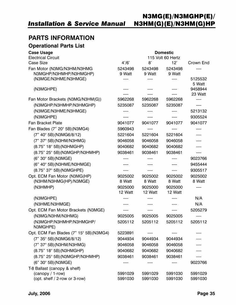
PARTS INFORMATIONOperational Parts ListCase Usage DomesticElectrical Circuit 115 Volt 60 HertzCase Size 4’/6’ 8’ 12’ Crown EndFan Motor (N3MG/N3HM/N3HMG 5243498 5243498 5243498 ----
N3MGHP/N3HMHP/N3HMGHP) 9 Watt 9 Watt 9 Watt(N3MGE/N3HME/N3HMGE) ---- ---- ---- 5125532
5 Watt(N3MGHPE) ---- ---- ---- 9458944
---- ---- ---- 23 WattFan Motor Brackets (N3MG/N3HM(G)) 5962268 5962268 5962268 ----
(N3MGHP/N3HMHP/N3HMGHP) 5235087 5235087 5235087 ----(N3MGE/N3HME/N3HMGE) ---- ---- ---- 5213132(N3MGHPE) ---- ---- ---- 9305524
Fan Bracket Plate 9041077 9041077 9041077 9041077Fan Blades (7” 20° 5B)(N3MG4) 5960943 ---- ---- ----
(7” 40° 5B)(N3MG6/8/12) 5221604 5221604 5221604 ----(7” 37° 5B)(N3HM/N3HMG) 9046058 9046058 9046058 ----(8.75” 18° 5B)(N3HMGHP) 9040682 9040682 9040682 ----(8.75” 25° 5B)(N3MGHP/N3HMHP) 9038461 9038461 9038461 ----(6” 30° 5B)(N3MGE) ---- ---- ---- 9023766(6” 40° 5B)(N3HME/N3HMGE) ---- ---- ---- 9455444(8.75” 37° 5B)(N3MGHPE) ---- ---- ---- 9305517
Opt. ECM Fan Motor (N3MG(HP) 9025002 9025002 9025002 9025002(N3HM/N3HMG(HP)/N3MGE) 8 Watt 8 Watt 8 Watt 8 Watt(N3HMHP) 9025000 9025000 9025000 ----
12 Watt 12 Watt 12 Watt(N3MGHPE) ---- ---- ---- N/A(N3HME/N3HMGE) ---- ---- ---- N/A
Opt. ECM Fan Motor Brackets (N3MGE) ---- ---- ---- 5205279(N3MG/N3HM/N3HMG) 9025005 9025005 9025005 ----(N3MGHP/N3HMHP/N3HMGHP/ 5205112 5205112 5205112 5205112N3MGHPE)
Opt. ECM Fan Blades (7” 15° 5B)(N3MG4) 5223891 ---- ---- ----(7” 35° 5B)(N3MG6/8/12) 9044934 9044934 9044934 ----(7” 37° 5B)(N3HM/N3HMG) 9046058 9046058 9046058 ----(8.75” 18° 5B)(N3HMGHP) 9040682 9040682 9040682 ----(8.75” 25° 5B)(N3MGHP/N3HMHP) 9038461 9038461 9038461 ----(6” 30° 5B)(N3MGE) ---- ---- ---- 9023766
T-8 Ballast (canopy & shelf)(canopy / 1-row) 5991029 5991029 5991030 5991029(opt. shelf / 2-row or 3-row) 5991030 5991030 5991030 5991030

N3MG(E)/N3MGHP(E)/N3HM(G)(E)/N3HM(G)HP
Page 36 April, 2007
Case Usage DomesticElectrical Circuit 115 Volt 60 HertzCase Size 4’/6’ 8’ 12’ Crown EndT-8 Lampholder (canopy or shelf) 9041897 9041897 9041897 ----Compact Light Lampholder (canopy or shelf) ---- ---- ---- 9450238Compact Light Clip (canopy or shelf) ---- ---- ---- 9450239Anti-Sweat Heater Wire (glass top) 9402089 (4’) 9039374 9039373 ----
9039375 (6’)(top light) 9403434 (4’) 9045395 9046396 9053348
9039372 (6’)Opt. Elec. Def. Heater ---- (4’)
(N3MG/N3HM/N3HMG) 5125153 (6’) 5124521 5124522 ----(N3MGE) ---- ---- ---- 9405782
Opt. Elec. Def. Limit Klixon 5125211 5125211 5125211 5125211(N3MG/N3HM/N3HMG/N3MGE)
Opt. Gas Def. Fan Delay Klixon 9023503 9023503 9023503 9023503(N3MG/N3HM/N3HMG/N3MGE)
Opt. Gas Def. Term. Klixon 9023508 9023508 9023508 9023508(N3MG/N3HM/N3HMG/N3MGE)
NSF Product Thermometer 5967100 5967100 5967100 5967100For information on operational parts not listed above contact the TYLER Service Parts Department.
Cladding and Trim Parts ListsN3MG/N3MGHP
Item Description 4’ 6’ 8’ 12’
1 Screw (per cover) 5100217 (2) 5100217 (2) 5100217 (2) 5100217 (2)
2 Joint Trim, Rear Riser 9042342 9042342 9042342 9042342
3 Glass Joint Trim 9025959 9025959 9025959 9025959
4 Screw 5048626 (2) 5048626 (2) 5048626 (2) 5048626 (2)
5 Color Band, Painted 9608486 9036804 9025239 9025240
6 Color Band Backer, Painted 9025653 9025653 9025653 9025653
7 Bumper Backer ------------------- color per order --------------------
8 Bumper End Trim ------------------- color per order --------------------
9 Bumper ------------------- color per order --------------------
10 Upper Front Cladding, Painted 9025219 9025129 9025130 9025131
11 Shoulder Screw, Bumper Ret. 9025833 (8) 9025833 (12) 9025833 (18) 9025833 (24)
12 Lower Front Cladding, Painted 9025218 9025120 9025121 9025122
13 Screw 5183536 (6) 5183536 (8) 5183536 (11) 5183536 (16)
14 Kickplate, Ptd. 9039267 9039015 9039016 9039017
Kickplate Joint Trim, Ptd. 9039020 9039020 9039020 9039020
Screw 9037551 (4) 9037551 (5) 9037551 (6) 9037551 (6)

Installation & Service ManualN3MG(E)/N3MGHP(E)/
N3HM(G)(E)/N3HM(G)HP
Page 37July, 2006
N3MG/N3MGHP
Item Description 4’ 6’ 8’ 12’
15 Kickplate Support 9039022 (2) 9039022 (3) 9039022 (4) 9039022 (4)
16 Screw 5183536 (4) 5183536 (6) 5183536 (8) 5183536 (8)
17 LH End Close-off, Painted 9022460 9022460 9022460 9022460
RH End Close-off, Painted 9022467 9022467 9022467 9022467
18 Screw 5048626 (6) 5048626 (6) 5048626 (6) 5048626 (6)
19 Raceway 9608484 5233273 5233274 5233275
20 Screw 5183536 (9) 5183536 (9) 5183536 (9) 5183536 (9)
21 Horizontal Joint Trim 5964733 5964733 5964733 5964733
22 Bumper Retainer 9025045 9025052 9025058 9025061

N3MG(E)/N3MGHP(E)/N3HM(G)(E)/N3HM(G)HP
Page 38 April, 2007
N3HM/N3HMHP/N3HMG/N3HMGHP
Item Description 6’ 8’ 12’
1 Screw (per cover) 5100217 (2) 5100217 (2) 5100217 (2)
2 Joint Trim, Rear Riser 9042604 9042604 9042604
3 Handrail Backer, Ptd. 9025316 9025316 9025316(N3HM(HP))
4 Glass Joint Trim (N3HMG(HP)) 9025959 9025959 9025959
5 Screw 5048626 (2) 5048626 (2) 5048626 (2)
6 Color Band, Ptd. (N3HM(HP)) 9023796 9023799 9023801
(N3HMG(HP)) 9025238 9025239 9025240
7 Color Band Backer, Ptd. 9040223 9040223 9040223(N3HM(HP))
(N3HMG(HP)) 9025653 9025653 9025653
8 Bumper Backer ----------- color per order ------------
9 Bumper End Trim ----------- color per order ------------
10 Bumper ----------- color per order ------------
11 Shoulder Screw, Bumper Ret. 9025833 (12) 9025833 (18) 9025833 (24)
12 Front Cladding, Ptd. (N3HM(HP)) 9046003 9046000 9044430
(N3HMG(HP)) 9046019 9046022 9046025
13 Screw 5100212 (7) 5100212 (7) 5100212 (7)
14 Lower Bumper ----------- color per order ------------
Lower Bumper End Caps (2) ----------- color per order ------------
Lower Bumper Retainer 9046446 9046447 9046448
Screw 9602398 (12) 9602398 (12) 9602398 (12)
15 Kickplate, Ptd. 9039017 9039017 9039017
Kickplate Joint Trim, Ptd. 9039020 9039020 9039020
Screw 9037551 (5) 9037551 (6) 9037551 (6)
16 Raceway 9045956 9044470 9045913
Screw 1309067 (16) 1309067 (16) 1309067 (16)
17 Kickplate Support 9043460 (3) 9043460 (4) 9043460 (4)
Screw 5183536 (6) 5183536 (8) 5183536 (8)
18 LH/RH End Close-off, Ptd. 9605202 9605202 9605202
19 Screw 5048626 (6) 5048626 (6) 5048626 (6)
20 Horizontal Joint Trim 5964733 5964733 5964733
21 Bumper Retainer (N3HM(HP)) ----------- color per order ------------
(N3HMG(HP)) 9025052 9025058 9025061

Installation & Service ManualN3MG(E)/N3MGHP(E)/
N3HM(G)(E)/N3HM(G)HP
Page 39July, 2006

N3MG(E)/N3MGHP(E)/N3HM(G)(E)/N3HM(G)HP
Page 40 April, 2007
N3MGE/N3MGHPE
Item Description CROWN END
1 Top Cladding, MB SST 9451257
2 Color Band, Ptd. (pre-cut sections) 94558602 - 17.220” Side Sections2 - 37.506” Center Sections1 - 34.440” Front Section
3. Bumper (pre-cut sections) color per order4 Bumper Retainer (pre-cut sections) 9408587
2 - 17.220” Side Sections2 - 37.506” Center Sections1 - 34.440” Front Section
5 RH Upr. Ext. Side Cladding, Ptd. 9408539
LH Upr. Ext. Side Cladding, Ptd. 9408538
6 Lower Front Cladding, Ptd. 9408624 (2)
7 Kickplate, Ptd. 9454852 (2)
8 Center Color Band, Ptd. 9455859 (2)
9 Upr. Ext. Center Cladding 9408540 (2)
10 Front Color Band, Ptd. 9455858
11 Upr. Ext. Front Cladding, Ptd. 9408541
12 Kickplate Joint Trim, Ptd. 9410544
13 Glass/Bumper Corner Trim, Ptd. 9406277 (4)
Corner Molding Retainer Bracket 9411615 (4)
14 Kickplate Support Assembly 9039022 (10)
Installation & Service ManualN3MG(E)/N3MGHP(E)/
N3HM(G)(E)/N3HM(G)HP
Page 41July, 2006
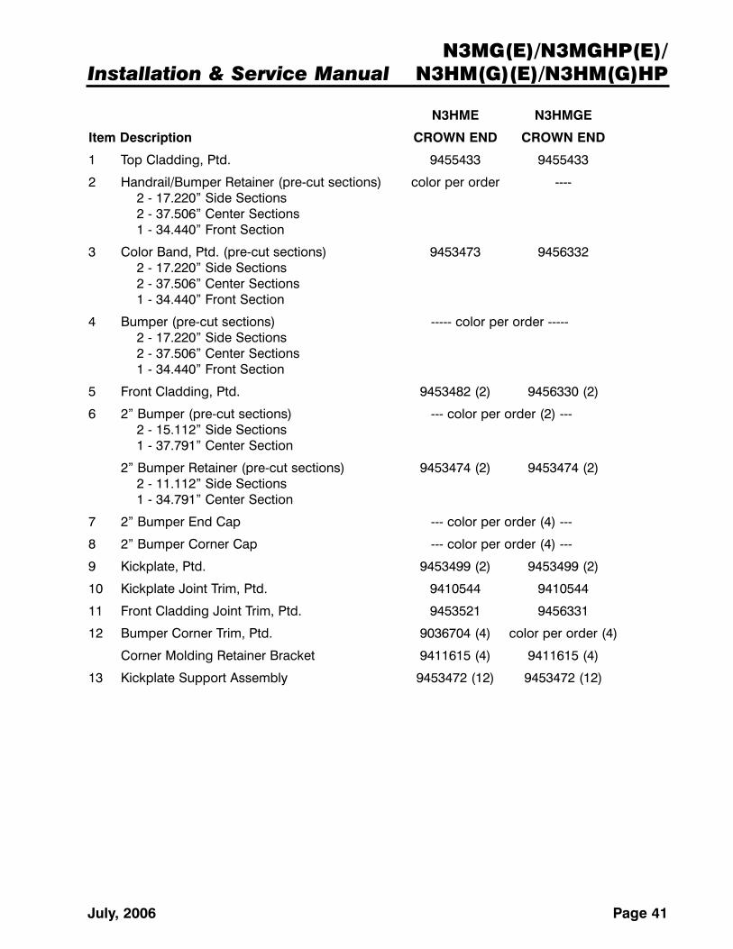
N3HME N3HMGE
Item Description CROWN END CROWN END
1 Top Cladding, Ptd. 9455433 9455433
2 Handrail/Bumper Retainer (pre-cut sections) color per order ----2 - 17.220” Side Sections2 - 37.506” Center Sections1 - 34.440” Front Section
3 Color Band, Ptd. (pre-cut sections) 9453473 94563322 - 17.220” Side Sections2 - 37.506” Center Sections1 - 34.440” Front Section
4 Bumper (pre-cut sections) ----- color per order -----2 - 17.220” Side Sections2 - 37.506” Center Sections1 - 34.440” Front Section
5 Front Cladding, Ptd. 9453482 (2) 9456330 (2)
6 2” Bumper (pre-cut sections) --- color per order (2) ---2 - 15.112” Side Sections1 - 37.791” Center Section
2” Bumper Retainer (pre-cut sections) 9453474 (2) 9453474 (2)2 - 11.112” Side Sections1 - 34.791” Center Section
7 2” Bumper End Cap --- color per order (4) ---
8 2” Bumper Corner Cap --- color per order (4) ---
9 Kickplate, Ptd. 9453499 (2) 9453499 (2)
10 Kickplate Joint Trim, Ptd. 9410544 9410544
11 Front Cladding Joint Trim, Ptd. 9453521 9456331
12 Bumper Corner Trim, Ptd. 9036704 (4) color per order (4)
Corner Molding Retainer Bracket 9411615 (4) 9411615 (4)
13 Kickplate Support Assembly 9453472 (12) 9453472 (12)

N3MG(E)/N3MGHP(E)/N3HM(G)(E)/N3HM(G)HP
Page 42 October, 2008
Revision LogThis log sheet is intended to track both major and minor revisions to this manual, and to describe what thenature of the revision is. Revision identification is located in the lower right corner of the cover page.
Major revisions are lettered alphabetically, dated accordingly, and require reprinting for inclusion with theproduct at shipment. Minor revisions are denoted after the major revision with a “period” followed by asequential number, and do not require a printed update. All manuals with any revision changes will be avail-able in electronic PDF format on the Tyler Refrigeration website.
Content changes that determine the type of revisions are decided on a case-by-case basis by Tyler internalmanagement. This revision log was created in October of 2008.
DATE
REVISION TYPE
DESCRIPTION RESULTSMAJOR MINOR
Oct 2008 F.1Changed wiring diagrams ...
Update Service Instructions ...
... added terminal blocks to electrical.
... added metal edge trim replacement.