Embed Size (px)
Citation preview
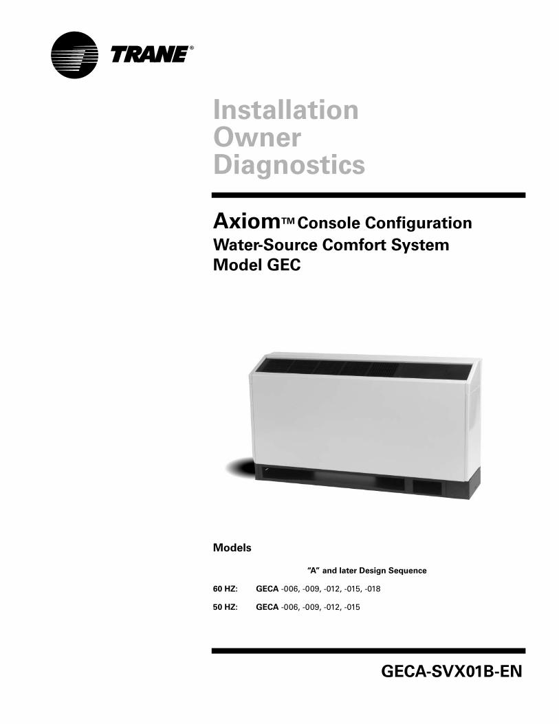
GECA-SVX01B-EN
Models
“A” and later Design Sequence
60 HZ: GECA -006, -009, -012, -015, -018
50 HZ: GECA -006, -009, -012, -015
InstallationOwnerDiagnostics
AxiomTM Console Configuration
Water-Source Comfort System
Model GEC

©2005 American Standard Inc. All rights reserved. GECA-SVX01B-EN
GeneralInformation
IntroductionThe GECA water-source comfort system contains standard features to enhance performance, serviceability and extend life of the equipment. Several of these features are shown below:
WATER
REGULATING
CONNECTION
WARNINGS / CAUTIONS
EXPLANATION:
Warnings are provided throughout this manual to indicate to installing contractors, operators, and service personnel potentially hazardous situations which, if not avoided, COULD result in death or serious injury.
WARNING!Cautions are provided throughout this manual to indicate to installing contractors, operators, and service personnel potentially hazardous situations which, if not avoided, MAY result in minor or moderate injury.
CAUTION!
GECA-SVX01B-EN 3
Contents
Installation/Startup/Commissioning 2
General Information 2
Pre-installation Checklist 4
Dimensions/Weights 5
Installation Instructions 19
Electrical Requirements 27
Pre-Startup Checklist 29
Startup/Commissioning 30
Sequence of Operation 31
Startup Checklist & Log 34
Maintenance 35
Warranty Information 37
Troubleshooting Checklist 38
Unit Wiring 39

4 GECA-SVX01B-EN
Jobsite StorageThis unit is intended for indoor use only. To protect the unit from damage due to the elements, and to prevent possible IAQ contaminant sources from growing, the unit should be stored indoors. If indoor storage is not possible, the following provisions for outdoor storage must be met.1. Place the unit(s) on a dry sur-
face or raise above the ground to assure adequate air circula-tion beneath the unit. This is to assure that no portion of the unit contacts standing water at any time.
2. Cover the unit(s) with a water proof tarp to protect them from the elements.
3. Make provisions for continu-ous venting of the covered units to prevent moisture from standing on the unit(s) sur-faces. Wet interior unit insulation can become an amplification site for microbial growth (mold) which
has been determined to be a cause of odors and serious health related indoor air quality problems.
4. Store units in the normal UP orientation. Storing units in this manner maintains oil in the com-pressor.
5. Units may be stacked two high.
Pre-installationChecklist
Jobsite InspectionEach unit has been inspected, tested and operated at the factory by pro-duction and quality associates prior to being crated for safe transit. How-ever, rough handling or accidents can occur resulting in damaged equipment being delivered. Always perform the following checks before accepting a unit:1. Do not sign the bill of lading
accepting the unit(s) until inspection has been com-pleted. Check for damage promptly after the unit(s) are unloaded. Once the bill of lading is signed at the jobsite, the unit(s) are now the property of the SOLD TO party and future freight claims MAY NOT be accepted by the freight company.
2. Check the unit model numbers on the bill of lading against those ordered and received to assure equipment is AS ORDERED.
3. Check to assure that the refrig-erant charge has been retained during shipment by use of gauges. Schrader taps are located and labeled internal to the cabinet. (See Figure 1).
Figure 1: Schrader location
HIGH
LOW
IMPORTANT!After assuring that charge has been retained:
Reinstall schrader caps to assure that refrigerant leakage does not occur.
Reinstall unit panel using all factory provided screws.
Notice
UNIT CONTAINS HCFC (R-22)REFRIGERANT
INSTRUCTIONS!
SECTION 608, PARAGRAPH C OF THE 1990 CLEAN AIR ACT STATES:
EFFECTIVE JULY 1, 1992, IT SHALL BE UNLAWFUL FOR ANY PERSON, IN COURSE OF
MAINTAINING, SERVICING, REPAIRING, OR DISPOSING OF AN AIR CONDITIONING SYS-
TEM, TO KNOWINGLY VENT OR RELEASE ANY CFC OR HCFC REFRIGERANT. MINIMAL
RELEASES (AIR PURGES OF REFRIGERANT HOSES) ASSOCIATED WITH GOOD FAITH
ATTEMPTS TO RECAPTURE OR RECYCLE ARE EXEMPT FROM THE BAN ON VENTING.
Important!Equipment is shipped FOB (Free on Board) at the manufacturer. There-fore, freight claims for damages against the carrier must be initiated by the receiver.
GECA-SVX01B-EN 5
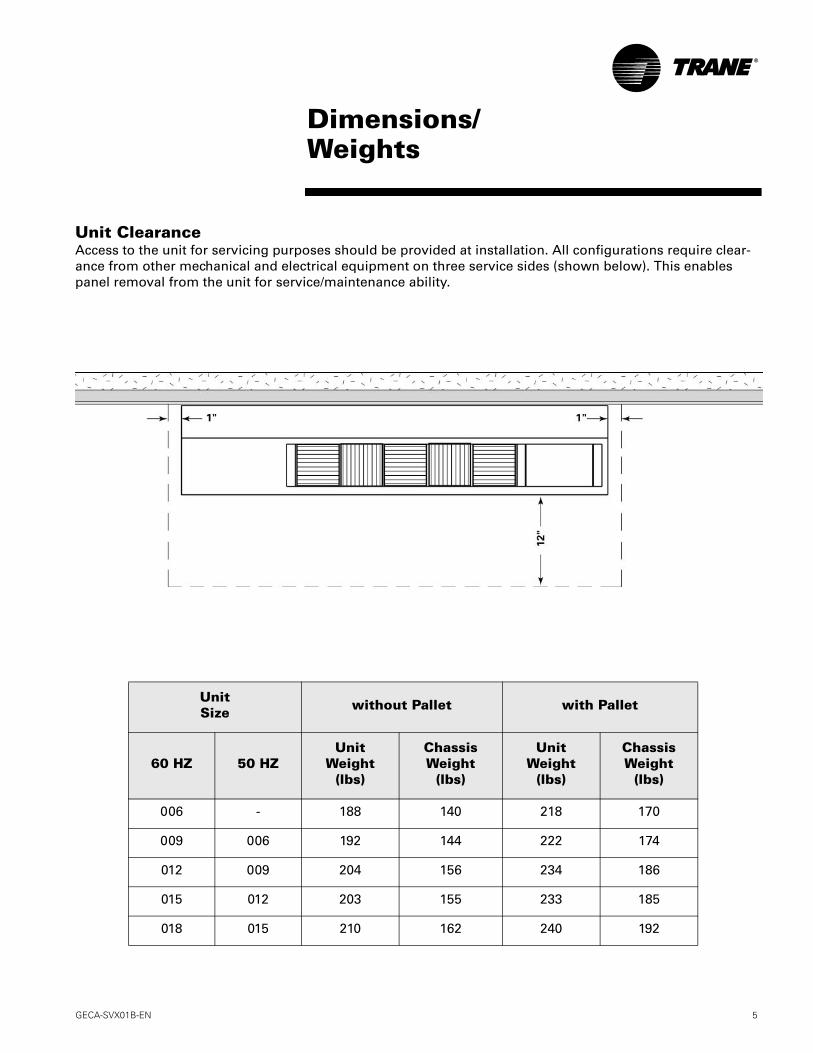
Dimensions/Weights
UnitSize without Pallet with Pallet
60 HZ 50 HZUnit
Weight(lbs)
ChassisWeight
(lbs)
UnitWeight
(lbs)
ChassisWeight
(lbs)
006 - 188 140 218 170
009 006 192 144 222 174
012 009 204 156 234 186
015 012 203 155 233 185
018 015 210 162 240 192
Unit ClearanceAccess to the unit for servicing purposes should be provided at installation. All configurations require clear-ance from other mechanical and electrical equipment on three service sides (shown below). This enables panel removal from the unit for service/maintenance ability.

6 GECA-SVX01B-EN
Dimensions/WeightsCabinet (RH) no Pump Kit
GECA-SVX01B-EN 7
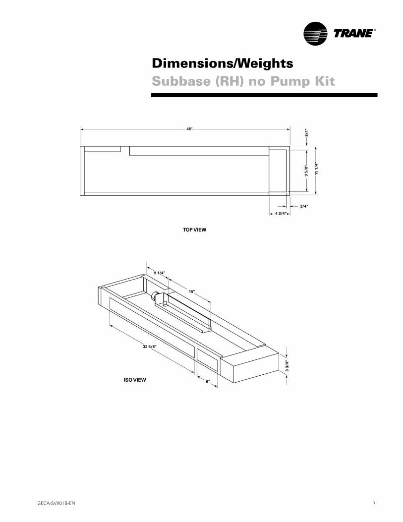
Dimensions/WeightsSubbase (RH) no Pump Kit

8 GECA-SVX01B-EN
Dimensions/WeightsCabinet (LH) no Pump Kit

GECA-SVX01B-EN 9
Dimensions/WeightsSubbase (LH) no Pump Kit
10 GECA-SVX01B-EN
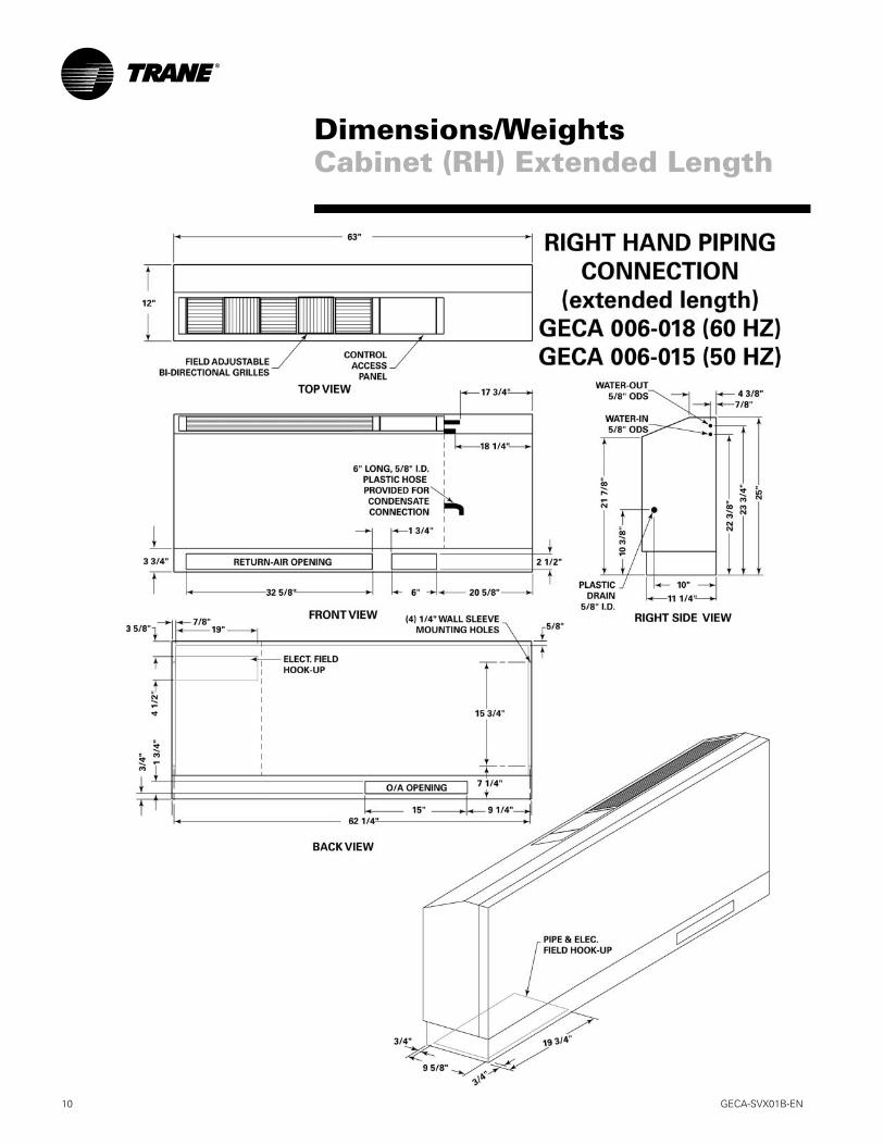
Dimensions/WeightsCabinet (RH) Extended Length

GECA-SVX01B-EN 11
Dimensions/WeightsSubbase (RH) Extended Length

12 GECA-SVX01B-EN
Dimensions/WeightsCabinet (LH) Extended Length

GECA-SVX01B-EN 13
Dimensions/WeightsSubbase (LH) Extended Length

14 GECA-SVX01B-EN
Dimensions/WeightsCabinet (RH) Low Height Unit

GECA-SVX01B-EN 15
Dimensions/WeightsCabinet (LH) Low Height Unit
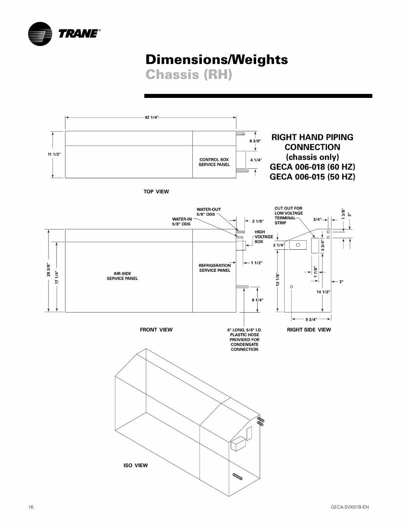
16 GECA-SVX01B-EN
Dimensions/WeightsChassis (RH)

GECA-SVX01B-EN 17
Dimensions/WeightsChassis (LH)

18 GECA-SVX01B-EN
Dimensions/WeightsPump Kit Option

GECA-SVX01B-EN 19
2
CHASSISREFRIGERATIONFRONT PANEL
43
1
Uncrate UnitRemove packaging and inspect the unit. Carefully re-move the stretch wrap and cardboard pieces. The in-stallation literature and Torx® head tool may be found on the back of the unit in a clear baggie. Unit has been tied to skid by (2) shipping brackets.
Inspect UnitRemove refrigeration panel and inspect the unit. Be certain the refrigerant tubing has clearance from adja-cent parts. Verify that the electrical connections are tight and in-place.
Mounting to WallWith the chassis still on the subbase, align the unit to the wall. If unit contains an outside air option, align the wall cut-out to the subbase outside-air cut-out. Level the unit per plan requirements. Mark the four mount-ing locations for wall sleeve mounting to the wall. The dimensions should fall in line with Step 5.
Remove ChassisRemove the chassis from the subbase via 6-Torx head screws. The chassis is attached to both the subbase and the wall sleeve (see diagram above). To assure proper alignment, re-install screws 2 and 3 in the final installation of the unit (Step 11).
InstallationInstructions

20 GECA-SVX01B-EN
InstallationInstructions
Wall FlangeAfter removing chassis from the subbase, install the wall flange assembly to the desired wall with the use of four #10-field provided screws. The wall flange as-sembly includes four, 1/4-inch in diameter clearance holes.
Mounting of Disconnect(circuit breaker-OPTION)Mounting of the circuit breaker/receptical box should be made prior to piping and electrical hook-up. This factory disconnect option is designed to fit inside the end pocket. Mount the electrical box flush with the subbase with four, #8-field supplied screws.
5 6
Mounting of Disconnect(receptical box-OPTION)Mounting of the receptical box should be made prior to piping and electrical hook-up. This factory discon-nect option is designed to fit inside the end pocket. Mount the receptical box 2-inches above the top of the subbase with four, #8-field supplied screws.
7 8
Wiring of Disconnect(OPTION)Power wiring to the equipment should be installed per national and local electric codes by a professional electrician.
Power wiring to the disconnect may be done at this time. See the unit’s wiring schematic for field wiring. The above schematic is for REFERENCE ONLY.

GECA-SVX01B-EN 21
InstallationInstructions
Verify Fit-upSlide the chassis onto the subbase to verify that field installed disconnects, condensate pipe, and supply/return pipe are in the appropriate locations and will not require adustments.
Verify water connection angle prior to brazing of the unit water-in/out.
Field PipingInspect the system water pipe thoroughly before con-necting the unit to the system. Water-to-refrigerant heat exchanger fouling, freezing and failure is immi-nent if the system pipe contains contaminants. All field piping must be cleaned of contaminants.
Replace ChassisSlide chassis back into place on the subbase. To as-sure proper alignment, reinstall the two front screws (2 and 3) that attach the chassis to the subbase.
9 Factory Recommendation: Unit’s re-ceiving the circuit breaker option should have water and condensate piping sup-
plied/returned through the bottom of the unit OR include the ex-
tended cabinet option.
11 12
10
Water ConnectionsWith the chassis on or off of the subbase, install the field provided water connections to the unit water-in/out pipe. Trane recommends a 1/2-inch x 3/4-inch nominal ell to be field brazed to the factory 1/2" nomi-nal water-in/out lines.
Water in/out copper size: 5/8-inch ODS or 1/2-inch nominal.

22 GECA-SVX01B-EN
InstallationInstructions
15Wiring Connections Power wiring to the equipment should be installed per national and local electric codes by a professional electrician.
Refer to STEPS 6, 7, and 8 for units that include the factory supplied disconnect.
For units containing a field pro-vided disconnect, or, are hard wired to the unit, Trane provides pig tail leads inside a 2 x 4 handy-box in either the right or left side end pocket. See unit wiring schematic for details.
For units containing a wall mounted ther-mostat, a low voltage (18-pole) terminal strip is provided for field installation of the thermostat. See STEP 18 for unit mounted controls.
13
Connect Supply/Return HosesConnect the supply and return line to the unit inlet and outlet. Flexible hoses reduce vibration from the water lines to the unit.
An isolation valve, p/t plugs and auto-flow valves are recommended to separate the closed/open loop from the mechanical device.
14
Connecting the DrainBecause the console configuration is a blow-through design, no condensate trapping is neccessary. Howev-er, it is neccessary for the condensate to run in a down-ward motion to allow gravity to properly drain the system.
The unit drain connection is 5/8-inch I.D. or 7/8" O.D. for all GECA 006-018 systems.
GECA-SVX01B-EN 23
InstallationInstructions
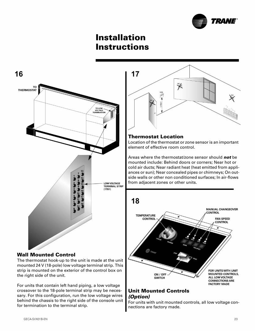
16
18
Wall Mounted ControlThe thermostat hook-up to the unit is made at the unit mounted 24 V (18-pole) low voltage terminal strip. This strip is mounted on the exterior of the control box on the right side of the unit.
For units that contain left hand piping, a low voltage crossover to the 18-pole terminal strip may be neces-sary. For this configuration, run the low voltage wires behind the chassis to the right side of the console unit for termination to the terminal strip.
Unit Mounted Controls(Option)For units with unit mounted controls, all low voltage con-nections are factory made.
17
Thermostat LocationLocation of the thermostat or zone sensor is an important element of effective room control.
Areas where the thermostat/zone sensor should not be mounted include: Behind doors or corners; Near hot or cold air ducts; Near radiant heat (heat emitted from appli-ances or sun); Near concealed pipes or chimneys; On out-side walls or other non conditioned surfaces; In air-flows from adjacent zones or other units.

24 GECA-SVX01B-EN
InstallationInstructions
Receptacle Plug(Option)For units with the factory provided disconnect op-tions, the receptacle plug may now be connected to the electrical outlet.
20
Factory Installed Pump Kit(Option)All wiring to the pump kit option is factory made. NO FIELD wiring will be required. Field hook-up to the sys-tem water loop is made at the bottom of the pump box. This side of the system is usually hard piped to the pump box.
A two-position valve is installed on the pump kit. A second shut-off valve will not be required at the unit. Con-nection from the pump kit to the unit is hard piped at the factory. This hard piped assembly contains pressure/temperature ports at the water-in/out union.
See literature number WSHPC-IN-5 (72-9006-03) for specific information related to the pump kit.
UNIT FRONT
19
GECA-SVX01B-EN 25
InstallationInstructions
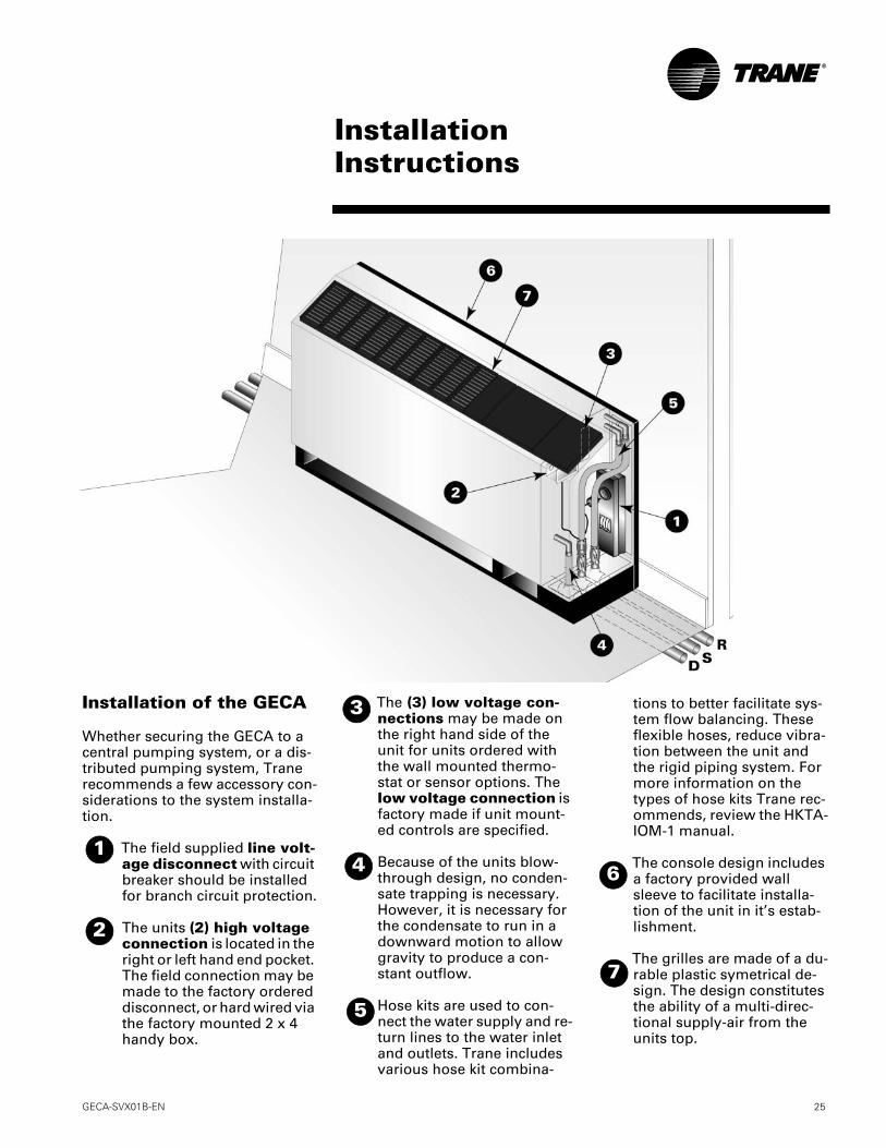
Installation of the GECA
Whether securing the GECA to a central pumping system, or a dis-tributed pumping system, Trane recommends a few accessory con-siderations to the system installa-tion.
The field supplied line volt-age disconnect with circuit breaker should be installed for branch circuit protection.
The units (2) high voltage connection is located in the right or left hand end pocket. The field connection may be made to the factory ordered disconnect, or hard wired via the factory mounted 2 x 4 handy box.
The (3) low voltage con-nections may be made on the right hand side of the unit for units ordered with the wall mounted thermo-stat or sensor options. The low voltage connection is factory made if unit mount-ed controls are specified.
Because of the units blow-through design, no conden-sate trapping is necessary. However, it is necessary for the condensate to run in a downward motion to allow gravity to produce a con-stant outflow.
Hose kits are used to con-nect the water supply and re-turn lines to the water inlet and outlets. Trane includes various hose kit combina-
tions to better facilitate sys-tem flow balancing. These flexible hoses, reduce vibra-tion between the unit and the rigid piping system. For more information on the types of hose kits Trane rec-ommends, review the HKTA-IOM-1 manual.
The console design includes a factory provided wall sleeve to facilitate installa-tion of the unit in it’s estab-lishment.
The grilles are made of a du-rable plastic symetrical de-sign. The design constitutes the ability of a multi-direc-tional supply-air from the units top.
2
1
3
4
5
6
7

26 GECA-SVX01B-EN
InstallationInstructions
Table M-1: Physical Data (GECA 006-012)
Model: GECA 006-012 60 HZ - 006 60 HZ - 00950 HZ - 006
60 HZ - 01250 HZ - 009
Unit Size
Length of cabinet (in) 48 or 63 48 or 63 48 or 63
Height (in) 25 or 22 1/2 25 or 22 1/2 25 or 22 1/2
Width (in) 12 12 12
Compressor Type Rotary Rotary Rotary
R-22 Refrigerant (lbs) Heating and Cooling 1.06 1.19 1.22
Cooling Only 0.94 1.06 1.16
Hot Gas Reheat n/a n/a 1.375
Approximate Weightwithout Pallet (lbs)
Unit 188 192 204
Chassis Only 140 144 156
Approximate Weightwith Pallet (lbs)
Unit 218 222 234
Chassis Only 170 174 186
Filter Size (standard height-25") 1 x 10 x 32 3/8 1 x 10 x 32 3/8 1 x 10 x 32 3/8
Filter Size (low height-22 1/2") 1 x 7 3/4 x 30 5/8 1 x 7 3/4 x 30 5/8 1 x 7 3/4 x 30 5/8
Blower Wheel Size (in) (1) 5 1/4 x 8 1/8 (2) 5 1/4 x 8 1/8 (2) 5 1/4 x 8 1/8
Table M-2: Physical Data (GECA 015-24)
Model: GECA 015-018 60 HZ - 01550 HZ - 012
60 HZ - 01850 HZ - 015
Unit Size
Length of cabinet (in) 48 or 63 48 or 63
Height (in) 25 or 22 1/2 25 or 22 1/2
Width (in) 12 12
Compressor Type Rotary Rotary
R-22 Refrigerant (lbs) Heating and Cooling 1.75 2.44
Cooling Only 1.5 1.88
Hot Gas Reheat n/a n/a
Approximate Weightwithout Pallet (lbs)
Unit 203 210
Chassis Only 155 162
Approximate Weightwith Pallet (lbs)
Unit 233 240
Chassis Only 185 192
Filter Size (standard height-25") 1 x 10 x 32 3/8 1 x 10 x 32 3/8
Filter Size (low height-22 1/2") 1 x 7 3/4 x 30 5/8 1 x 7 3/4 x 30 5/8
Blower Wheel Size (in) (2) 5 1/4 x 8 1/8 (2) 5 1/4 x 8 1/8

GECA-SVX01B-EN 27
Electrical RequirementsUnits w/o Pump Kit
Table E-1: GECA electrical performance Model No.
GECA Volts Total
FLAComp.RLA(ea)
Comp.LRA(ea)
No. ofCompres.
CmpMCC
BlowerMotorFLA
BlowerMotor
HP
Fan MotorNum
MinimumCircuit
Ampacity
OvercurrentProtective
Device
Electric Heat
SIZE kW Amps
006
115/60/1 6.5 5.6 36.2 1 9.1 0.90 1/20 1 8.2 15 None 0 0208/60/1 3.6 2.76 17.7 1 4.6 0.80 1/20 1 4.5 15 None 0 0208/60/1 11.6 2.76 17.7 1 4.6 0.80 1/20 1 14.5 15 Min 2.25 10.82208/60/1 15.2 2.76 17.7 1 4.6 0.80 1/20 1 19.0 20 Max 3 14.42230/60/1 3.5 2.76 17.7 1 4.6 0.70 1/20 1 4.4 15 None 0 0230/60/1 13.2 2.76 17.7 1 4.6 0.70 1/20 1 16.5 20 Min 3 12.5
220-240/50/1 3.8 3.10 18.8 1 5.2 0.70 1/20 1 4.9 15 None 0 0220-240/50/1 13.2 3.10 18.8 1 5.2 0.70 1/20 1 16.5 20 Min 3 12.5
265/60/1 3.2 2.45 15.0 1 3.9 0.70 1/20 1 3.8 15 None 0 0265/60/1 11.5 2.45 15.0 1 3.9 0.70 1/20 1 14.4 15 Min 3 10.83
009
115/60/1 8.1 7.20 45.6 1 10.9 0.90 1/20 1 9.9 15 None 0 0208/60/1 4.2 3.40 22.2 1 6.4 0.80 1/20 1 5.9 15 None 0 0208/60/1 11.6 3.40 22.2 1 6.4 0.80 1/20 1 14.5 15 Min 2.25 10.82208/60/1 15.2 3.40 22.2 1 6.4 0.80 1/20 1 19.0 20 Max 3 14.42230/60/1 4.1 3.40 22.2 1 6.4 0.70 1/20 1 5.8 15 None 0 0230/60/1 13.2 3.40 22.2 1 6.4 0.70 1/20 1 16.5 20 Min 3 12.5230/60/1 17.4 3.40 22.2 1 6.4 0.70 1/20 1 21.7 25 Max 4 16.67
220-240/50/1 5.0 4.30 22.2 1 6.6 0.70 1/12 1 6.1 15 None 0 0220-240/50/1 13.2 4.30 22.2 1 6.6 0.70 1/12 1 16.5 20 Min 3 12.5220-240/50/1 17.4 4.30 22.2 1 6.6 0.70 1/12 1 21.7 25 Max 4 16.67
265/60/1 3.8 3.10 18.8 1 5.2 0.70 1/20 1 4.9 15 None 0 0265/60/1 11.5 3.10 18.8 1 5.2 0.70 1/20 1 14.4 15 Min 3 10.83265/60/1 15.1 3.10 18.8 1 5.2 0.70 1/20 1 18.9 20 Max 4 14.44
012
115/60/1 11.8 10.60 56.7 1 16.0 1.20 1/12 1 14.5 25 None 0 0208/60/1 5.9 5.00 27.9 1 8.3 0.90 1/12 1 7.6 15 None 0 0208/60/1 11.7 5.00 27.9 1 8.3 0.90 1/12 1 14.7 15 Min 2.25 10.82208/60/1 15.3 5.00 27.9 1 8.3 0.90 1/12 1 19.2 20 Max 3 14.42230/60/1 5.7 5.00 27.9 1 8.3 0.70 1/12 1 7.4 15 None 0 0230/60/1 13.2 5.00 27.9 1 8.3 0.70 1/12 1 16.5 20 Min 3 12.5230/60/1 17.4 5.00 27.9 1 8.3 0.70 1/12 1 21.7 25 Max 4 16.67
220-240/50/1 5.5 4.80 27.0 1 8.5 0.70 1/12 1 7.5 15 None 0 0220-240/50/1 13.2 4.80 27.0 1 8.5 0.70 1/12 1 16.5 20 Min 3 12.5220-240/50/1 17.4 4.80 27.0 1 8.5 0.70 1/12 1 21.7 25 Max 4 16.67
265/60/1 5.0 4.30 22.2 1 6.6 0.70 1/12 1 6.1 15 None 0 0265/60/1 11.5 4.30 22.2 1 6.6 0.70 1/12 1 14.4 15 Min 3 10.83265/60/1 15.1 4.30 22.2 1 6.6 0.70 1/12 1 18.9 20 Max 4 14.44
015
115/60/1 12.6 11.40 67.0 1 17.6 1.20 1/12 1 15.5 25 None 0 0208/60/1 6.4 5.40 29.0 1 9.2 1.00 1/12 1 8.4 15 None 0 0208/60/1 11.8 5.40 29.0 1 9.2 1.00 1/12 1 14.8 15 Min 2.25 10.82208/60/1 15.4 5.40 29.0 1 9.2 1.00 1/12 1 19.3 20 Max 3 14.42230/60/1 6.3 5.40 29.0 1 9.2 0.90 1/12 1 8.3 15 None 0 0230/60/1 13.4 5.40 29.0 1 9.2 0.90 1/12 1 16.8 20 Min 3 12.5230/60/1 17.6 5.40 29.0 1 9.2 0.90 1/12 1 22.0 25 Max 4 16.67
220-240/50/1 6.1 5.40 32.0 1 8.6 0.70 1/12 1 7.6 15 None 0 0220-240/50/1 13.2 5.40 32.0 1 8.6 0.70 1/6 1 16.5 20 Min 3 12.5220-240/50/1 17.4 5.40 32.0 1 8.6 0.70 1/6 1 21.7 25 Max 4 16.67
265/60/1 5.5 4.80 27.0 1 8.5 0.70 1/6 1 7.5 15 None 0 0265/60/1 11.5 4.80 27.0 1 8.5 0.70 1/12 1 14.4 15 Min 3 10.83265/60/1 15.1 4.80 27.0 1 8.5 0.70 1/12 1 18.9 20 Max 4 14.44
018
208/60/1 7.4 6.40 38.0 1 11.0 1.00 1/12 1 9.8 15 None 0 0208/60/1 11.8 6.40 38.0 1 11.0 1.00 1/6 1 14.8 15 Min 2.25 10.82208/60/1 15.4 6.40 38.0 1 11.0 1.00 1/6 1 19.3 20 Max 3 14.42230/60/1 7.3 6.40 38.0 1 11.0 0.90 1/6 1 9.7 15 None 0 0230/60/1 13.4 6.40 38.0 1 11.0 0.90 1/6 1 16.8 20 Min 3 12.5230/60/1 17.6 6.40 38.0 1 11.0 0.90 1/6 1 22.0 25 Max 4 16.67265/60/1 6.1 5.40 32.0 1 8.6 0.70 1/6 1 7.6 15 None 0 0265/60/1 11.5 5.40 32.0 1 8.6 0.70 1/6 1 14.4 15 Min 3 10.83265/60/1 15.1 5.40 32.0 1 8.6 0.70 1/6 1 18.9 20 Max 4 14.44

28 GECA-SVX01B-EN
Pump Kit InformationThe pump module is a self-contained pumping package for earth-coupled heat pump systems. This kit contains thecomponents for the operation of a closed-loop earth-coupled heat pump water circuit system. The kit contains:
• One Grundfos pump 1/6 HP, 230V, 1PH
• Pump rated at 16 GPM at 20-feet of head
• 3-way brass shut-off valve
• Insulated cabinet
See Pump Module Kit manual WSHPC-IN-5 (72-9006-03) for pump module start-up and maintenance.
Table E-2: GECA electrical performance Model No.
GECA60 HZ
Volts TotalFLA
Comp.RLA(ea)
Comp.LRA(ea)
No. ofCompr.
CmpMCC
BlowerMotorFLA
BlowerMotor
HP
Fan MotorNum
MinimumCircuit
Ampacity
OvercurrentProtective
Device
Electric Heat
SIZE kW Amps
006 230/60/1 3.5 2.76 17.7 1 4.6 0.70 1/20 1 5.5 15 None 0 0230/60/1 13.2 2.76 17.7 1 4.6 0.70 1/20 1 16.5 20 Min 3 12.5
009230/60/1 4.1 3.40 22.2 1 6.4 0.70 1/20 1 6.9 15 None 0 0230/60/1 13.2 3.40 22.2 1 6.4 0.70 1/20 1 16.5 20 Min 3 12.5230/60/1 17.4 3.40 22.2 1 6.4 0.70 1/20 1 21.7 25 Max 4 16.67
012
230/60/1 5.7 5.00 27.9 1 8.3 0.70 1/12 1 8.4 15 None 0 0230/60/1 13.2 5.00 27.9 1 8.3 0.70 1/12 1 16.5 20 Min 3 12.5230/60/1 17.4 5.00 27.9 1 8.3 0.70 1/12 1 21.7 25 Max 4 16.67
015 230/60/1 6.3 5.40 29.0 1 9.2 0.90 1/12 1 9.3 15 None 0 0230/60/1 13.4 5.40 29.0 1 9.2 0.90 1/12 1 16.8 20 Min 3 12.5230/60/1 17.6 5.40 29.0 1 9.2 0.90 1/12 1 22 25 Max 4 16.67
018230/60/1 7.3 6.40 38.0 1 11.0 0.90 1/6 1 10.8 15 None 0 0230/60/1 13.4 6.40 38.0 1 11.0 0.90 1/6 1 16.8 20 Min 3 12.5230/60/1 17.6 6.40 38.0 1 11.0 0.90 1/6 1 22.0 25 Max 4 16.67
Electrical RequirementsUnits w/ Pump Kit

GECA-SVX01B-EN 29
Pre-Startup ChecklistBefore energizing the unit, the following system devices must be checked:
Is the high voltage power supply correct and in accordance with the nameplate ratings?
Is phasing of the unit correct per compressor rotation (scroll compressor only)?
Is the field wiring and circuit protection the correct size?
Is the low voltage control circuit wiring correct per the unit wiring diagram?
Is the piping system clean/complete and correct? (A recommendation of all system flushing of debris from the water-to-refrigerant heat exchanger, along with air purging from the water-to-refrigerant heat exchanger be done in accordance with the Closed-Loop/Ground Source Heat Pump Systems Installation Guide).
Is vibration isolation provided? (i.e. unit isolation pad, hosekits)
Is unit serviceable? (Allow a 12-inch clearance at the unit front for serviceability).
Are the low/high-side pressure temperature caps secure and in place?
Are all the unit access panels secure and in place?
Is the thermostat in the OFF position?
Is the water flow established and circulating through all the units?
Is the duct work correctly sized, run, taped, insulated and weather proofed with proper unit arrangement?
Is the condensate line properly sized, run, and pitched?
Is the zone sensor (when used) correctly wired and in a good location?
Does the indoor blower turn freely without rubbing?
Has all work been done in accordance with applicable local and national codes?
Has heat transfer fluid been added in the proper mix to prevent freezing in closed system application?
Pre-StartupChecklist
30 GECA-SVX01B-EN
Sequence ofOperation
Initial Unit Start-up
Note:Start-up for the TracerTM ZN510 Controller may be found in WSHP-IOP-2.
Start-up with the conventional thermostat is included below:
1.Set the thermostat to the highest position.
2.Set the thermostat system switch to COOL with the fan control to AUTO. The compres-sor should NOT run.
3.Reduce the thermostat setting until the compressor, reversing valve, solenoid valve, and loop pump are energized. Adjust water flow utilizing pressure/temperature plugs and comparing to tables contained in specification sheet data. Water leaving the heat exchanger should be warmer than the entering water temperature (approximately 9-12 F); blower operation should be smooth; compressor and blower amps should be within data plate ratings; the suction line should be cool with no frost observed in the refriger-ant circuit.
4.Check the cooling refrigerant pressures against values in Table 1. (Page 31).
5.Turn the thermostat system switch to the OFF position. Unit should stop running and the reversing valve should de-energize.
6.Leave unit off for approximately FIVE minutes to allow for pressure equalization.
7.Turn the thermostat to the lowest setting.
8.Set the thermostat system switch to the HEAT position.
9.Adjust the temperature setting upward until the unit is energized. Warm air should blow from the register. A water temperature decrease of approximately 5-9 F leaving the heat exchanger should be noted. The blower and compressor operation should be smooth with no frost observed in the refrigeration circuit.
10.Check the heating refrigerant pressures against values in Table 1. (Page 31)
11.Set the thermostat to maintain the desired space temperature.
12.Instruct the owner on system operation.

GECA-SVX01B-EN 31
Operating PressuresGENERAL: There are many variables (airflow, air temperatures) in an air conditioning system that will affect operating refrigerant pressures and temperatures. The charts below shows approximate conditions and is based on air flow at the rated SCFM, entering air at 80.6 °F(DB), 66.2 °F(WB) in cooling, 68 °F(DB) in heating. (+)Heating data with 35 °F EWT is based on the use of an anti-freeze solution having a freezing point 20 °F lower than the minimum expected entering temperature.Table 1: Operating pressures in cooling/heating for unit sizes 006-018
Operating DataModelGECA
Entering Water Temp,
°F
WaterFlowGPM
Cooling HeatingSuction Pres-
sure,PSIG
Discharge Pressure,
PSIG
WaterTemp Rise
°F
Air TempDrop°F DB
SuctionPressure
PSIG
Discharge Pressure
PSIG
Water TempDrop
°F
Air TempRise
°F DB
60 HZ006
35° 1.4 38-44 158-204 6-7 15-211.8 40-48 162-208 5-6 15-21
45° 1.4 75-85 135-174 13-17 22-28 48-56 170-218 7-9 18-261.8 75-85 133-169 10-13 22-28 52-60 173-223 6-7 18-26
55° 1.4 75-85 131-169 12-16 21-27 59-69 183-235 8-10 22-321.8 75-85 128-163 10-13 22-28 63-73 186-240 7-8 23-31
68° 1.4 77-87 145-187 11-15 21-27 74-86 200-256 10-12 27-371.8 77-87 143-182 9-12 21-27 78-90 204-262 8-10 27-37
75° 1.4 78-88 165-212 11-15 21-27 82-96 207-265 10-13 29-391.8 78-88 161-205 9-12 21-27 87-101 212-272 8-11 29-39
86° 1.4 79-89 197-255 11-15 20-26 98-112 223-285 12-15 31-431.8 79-89 192-246 9-12 20-26 101-117 226-290 9-12 32-44
95° 1.4 80-90 230-290 11-15 20-261.8 80-90 222-282 9-12 20-26
60 HZ009
50 HZ006
35° 1.8 41-47 159-205 6-8 18-242.3 42-48 162-208 4-6 19-25
45° 1.8 72-82 119-157 12-16 22-28 51-59 171-219 7-9 22-282.3 72-82 119-155 8-12 22-28 52-60 173-221 6-8 22-30
55° 1.8 74-84 122-160 11-15 21-27 60-70 181-231 8-10 25-332.3 72-84 120-156 8-12 21-27 62-72 182-234 6-8 26-34
68° 1.8 74-86 143-185 11-15 21-27 74-86 194-250 10-12 28-382.3 74-86 139-181 9-11 21-27 77-89 197-253 8-10 30-38
75° 1.8 75-87 163-211 11-15 21-27 82-96 202-260 10-14 30-402.3 75-87 158-204 9-11 21-27 85-99 205-263 8-10 31-41
86° 1.8 77-89 199-255 11-15 21-27 94-108 212-272 11-15 33-432.3 76-88 193-247 8-12 21-27 94-110 214-276 9-11 34-44
95° 1.8 78-90 231-295 11-15 20-262.3 77-89 223-285 8-12 20-26
60 HZ012
50 HZ009
35° 2.6 46-54 188-232 6-8 24-303.3 48-56 191-235 5-7 24-30
45° 2.6 69-79 90-132 10-14 22-28 56-64 200-246 7-9 27-333.3 68-80 87-127 8-12 22-28 58-66 202-248 6-8 27-35
55° 2.6 69-81 115-151 10-14 22-28 67-75 208-258 8-10 29-373.3 70-80 111-147 8-12 22-28 67-77 210-260 7-9 30-38
68° 2.6 70-82 143-187 10-14 21-27 73-83 214-264 9-11 31-393.3 70-82 139-181 8-12 21-27 74-84 216-268 7-9 32-40
75° 2.6 71-83 160-208 10-14 21-27 78-88 221-273 9-11 33-413.3 71-83 155-203 8-12 21-27 81-93 226-278 7-9 33-43
86° 2.6 72-84 189-245 10-14 20-26 91-101 236-290 10-14 37-453.3 72-84 184-238 8-12 20-26 96-108 242-296 8-10 37-47
95° 2.6 74-86 214-278 10-14 20-263.3 73-85 207-271 9-11 20-26
60 HZ015
50 HZ012
35° 2.9 36-42 159-205 5-7 18-243.6 37-45 160-224 4-6 20-26
45° 2.9 72-82 114-146 12-16 23-29 45-53 169-217 6-8 21-293.6 71-83 109-141 10-14 23-29 47-55 171-221 5-7 23-29
55° 2.9 73-83 124-160 11-15 22-28 52-62 177-231 7-9 24-323.6 72-84 120-154 10-12 22-28 55-65 181-235 6-8 25-33
68° 2.9 73-85 155-197 11-15 22-28 63-75 190-248 7-11 28-363.6 73-85 150-190 8-12 22-28 67-79 195-253 7-9 29-37
75° 2.9 74-86 173-219 11-15 21-27 71-83 199-257 9-11 29-393.6 74-86 168-212 8-12 21-27 75-87 203-263 8-10 31-39
86° 2.9 75-87 202-258 11-15 21-27 81-95 212-272 11-13 33-433.6 75-87 196-250 9-11 21-27 87-101 218-278 9-11 34-44
95° 2.9 76-88 229-293 11-15 20-263.6 76-88 221-283 9-11 21-27
Sequence ofOperation

32 GECA-SVX01B-EN
Operating DataModelGEVA
Entering Water Temp,
°F
WaterFlowGPM
Cooling HeatingSuction Pres-
sure,PSIG
Discharge Pressure,
PSIG
WaterTemp Rise
°F
Air TempDrop°F DB
SuctionPressure
PSIG
Discharge Pressure
PSIG
Water TempDrop
°F
Air TempRise
°F DB
60HZ018
50 HZ015
35° 3.8 37-43 165-207 4-6 20-264.8 38-44 167-209 3-5 21-27
45° 3.8 73-85 106-138 10-14 23-29 48-56 174-220 5-7 23-294.8 74-84 103-133 8-12 23-29 50-58 176-222 4-6 23-31
55° 3.8 74-86 126-162 9-13 23-29 57-67 184-232 6-8 26-344.8 75-85 123-159 7-11 23-29 60-70 187-235 5-7 26-34
68° 3.8 75-87 143-185 9-13 23-29 71-81 198-250 8-10 30-384.8 75-87 139-179 7-11 23-29 74-84 202-254 6-8 31-39
75° 3.8 75-87 161-207 9-13 22-28 78-90 206-260 8-10 32-424.8 75-87 157-201 7-11 22-28 82-94 211-265 7-9 33-43
86° 3.8 76-88 192-246 9-13 22-28 91-105 221-277 9-13 36-464.8 76-88 187-239 7-11 22-28 95-109 225-283 7-11 37-47
95° 3.8 77-89 219-281 9-13 22-284.8 77-89 212-272 7-11 22-28
Sequence ofOperation
GECA-SVX01B-EN 33
Sequence ofOperation
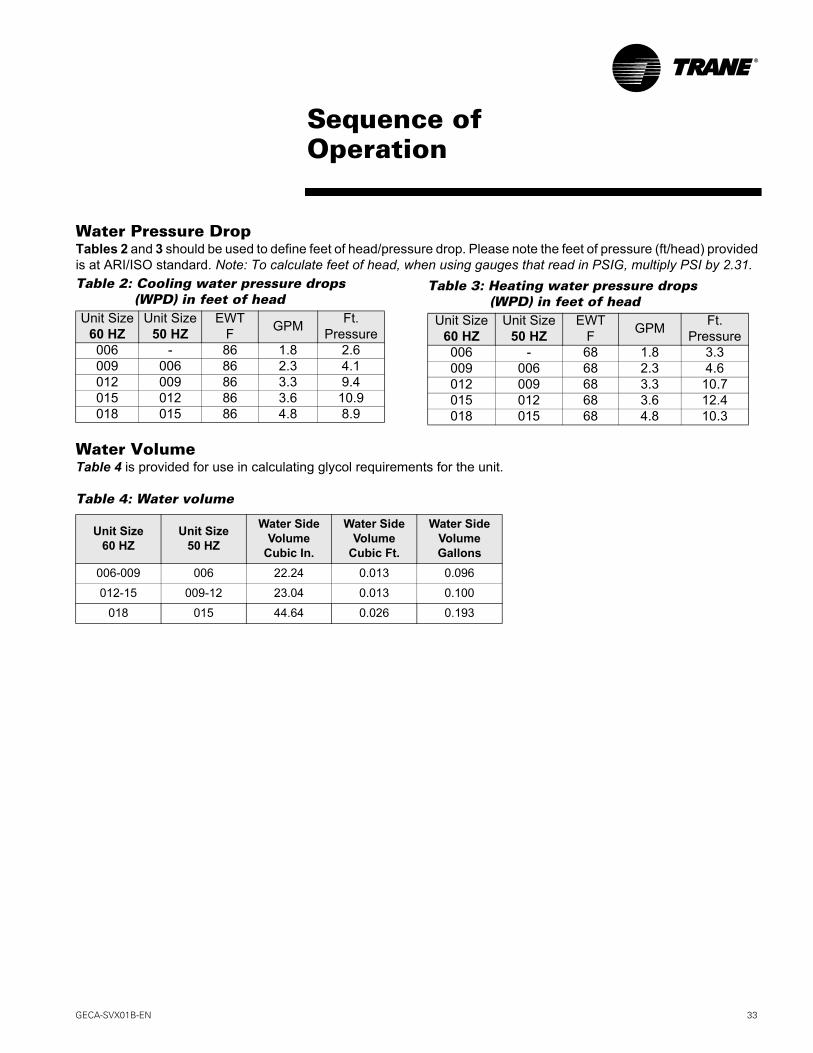
Water Pressure DropTables 2 and 3 should be used to define feet of head/pressure drop. Please note the feet of pressure (ft/head) provided is at ARI/ISO standard. Note: To calculate feet of head, when using gauges that read in PSIG, multiply PSI by 2.31.Table 2: Cooling water pressure drops
(WPD) in feet of headUnit Size
60 HZUnit Size
50 HZEWT
F GPM Ft.Pressure
006 - 86 1.8 2.6009 006 86 2.3 4.1012 009 86 3.3 9.4015 012 86 3.6 10.9018 015 86 4.8 8.9
Water VolumeTable 4 is provided for use in calculating glycol requirements for the unit.
Table 4: Water volume
Unit Size60 HZ
Unit Size50 HZ
Water Side Volume
Cubic In.
Water Side Volume
Cubic Ft.
Water Side VolumeGallons
006-009 006 22.24 0.013 0.096
012-15 009-12 23.04 0.013 0.100
018 015 44.64 0.026 0.193
Table 3: Heating water pressure drops (WPD) in feet of headUnit Size
60 HZUnit Size
50 HZEWT
F GPM Ft. Pressure
006 - 68 1.8 3.3009 006 68 2.3 4.6012 009 68 3.3 10.7015 012 68 3.6 12.4018 015 68 4.8 10.3

34 GECA-SVX01B-EN
Startup Checklistand Log
Installing Contractor: Use this form to thoroughly check-out the system and units before and during start-up.(This form need not be returned to the factory unless requested during technical service support).
Job Name:Model Number:Date:Serial Number:
In order to minimize troubleshooting and costly system failures, complete the following checks and data entriesbefore the system is put into full operation.
MODE
Entering fluid temperature
Leaving fluid temperature
Temperature differential
Return-air temperature DB/WB
Supply-air temperature DB/WB
Temperature differential
Water coil heat exchanger(Water Pressure IN)
Water coil heat exchanger(Water Pressure OUT)
Pressure Differential
HEAT
F
COOL
F
F F
F F
PSIG PSIG
PSIG PSIG
PSIG PSIG
COMPRESSOR
Amps
Volts
Discharge line temperature(after 10 minutes)
F F
F F
F F
F F

GECA-SVX01B-EN 35
Preventive MaintenanceMaintenance on the unit is simplified with the following preventive sugges-tions:
Filter maintenance must be per-formed to assure proper opera-tion of the equipment. Filters should be inspected at least ev-ery three months, and replaced when it is evident they are dirty. Filter sizing includes:
Check the contactors and relays within the control panel at least once a year. It is good practice to check the tightness of the various wiring connections within the control panel.
A strainer (60 mesh or greater) must be used on an open loop system to keep debris from en-tering the unit heat exchanger and to ensure a clean system.
Unit Size50/60 HZ
Filter Sizenominal inch
006-018 10 x 32 3/8 (std height unit)
006-018 7 3/4 x 30 5/8(low height unit)
For units on well water, it is im-portant to check the cleanliness of the water-to-refrigerant heat exchanger. Should it become contaminated with dirt and scal-ing as a result of bad water, the heat exchanger will have to be back flushed and cleaned with a chemical that will remove the scale. This service should be performed by an experienced service person.It should be noted that the water quality should be checked peri-odically. (See Table 5).
Table 5: Water Quality Table
ScalingCalcium and magnesium (total hardness)
Less than 350 ppm
CorrosionpH 7-9.5
Hydrogen Sulfide Less than 1 ppm
Sulfates Less than 25 ppm
Chlorides Less than 125 ppm
Carbon Dioxide Less than 75 ppm
Total dissolved solids (TDS)
Less than 1000 ppm
Biological GrowthIron Bacteria Low
ErosionSuspended Solids Low
Maintenance

36 GECA-SVX01B-EN
Filter Replacement(standard height configuration)
Filter replacement is done at the front return-air opening of the console unit. No tools are required for the replace-ment. The maintenence process is done via a 3-STEP process (See Figure 2 for filter replacement):
STEP 1: Through the return-air opening, slide filter to the back of the con-sole unit.
STEP 2: Allow the front edge of the filter to drop to floor level.
STEP 3: Pull the filter out of the front opening.
REVERSE the cycle to install a new filter.
Filter Replacement(low height configuration)
Filter replacement is done at the front return-air opening of the console unit. A slotted screw driver is needed for the replacement. The maintenence process is done via a 2-STEP pro-cess (See Figure 3 for filter re-placement):
STEP 1: Insert screw-driver and depress grill tab (2-per grille). Rotate grille down, and lift grille up-ward to remove grille.
STEP 2: Remove the filter through the grille hole in the cabinet front panel.
REVERSE the cycle to install a new filter.
Maintenance
Figure 2: Filter replacement for unit with subbase
Figure 3: Filter replacement for low height configuration
GECA-SVX01B-EN 37
Warranty Information
Standard WarrantyThe standard water-source heat pump warranty is The Trane Company parts-only warranty, running 12 months from startup, not to exceed 18-months from shipment.
Extended WarrantyThe optional extended warranty is a second through fifth year warranty. The time starts at the end of the standard 1-year coverage through the fifth year.
These extended warranties apply only to new equipment installed in domestic Worldwide Applied Systems Group sales territories and must be ordered prior to startup.
WarrantyInformation

38 GECA-SVX01B-EN
TroubleshootingChecklist
Problem Heating Cooling Cause Correction
No response to anythermostat setting
X X Main power off Check fusesX X Defective control transformer ReplaceX X Broken or loose connection RepairX X Defective thermostat ReplaceX X Transformer Reset Transformer
Unit short cyclesX X Thermostat or sensor improperly located Relocate
X X Unit contains unit mounted thermostat Change jumper on thermostat from 2-degrees to 4-degrees
Blower runs, but compressor does not
X X Defective compressor overload Replace (if external)X X Defective compressor contactor ReplaceX X Supply Voltage too low CorrectX X Defective compressor capacitor ReplaceX X Defective windings ReplaceX X Limit switches open Check cause/Replace or repair
Insufficient capacity
X X Dirty filter Replace/cleanX X Blower RPM too low Correct
X X Loss of conditioned air due to leaks in ductwork Repair leaks
X Introduction of excessively hot return-air CorrectX Introduction of excessively cold return-air Correct
X X Low on refrigerant charge Locate leak, repair and recharge by weight (not by superheat)
X X Restricted thermal expansion valve ReplaceX X Defective reversing valve See WSHP-IOM-# for touch test chartX X Thermostat improperly located RelocateX X Unit undersized Recalculate heat gains/lossesX X Inadequate water flow Increase GPMX X Scaling in heat exchanger Clean or replace
X Water too hot Decrease temperatureX Water too cold Increase temperature
High pressure switch open
X Inadequate GPM Increase water flow to unitX Water too hot Decrease temperature
X Inadequate air flow Check, clean blower and coilX Dirty filter Clean/replaceX X Overcharged with refrigerant Decrease chargeX X Defective pressure switch Check or replace
High head pressure
X Trash in heat exchanger BackflushX Low water flow Increase GPM
X X Overcharge of refrigerant Decrease chargeX X Non-condensable in system Evacuate and recharge by weightX X Water too hot Decrease temperatureX Dirty filter Clean / replaceX Inadequate air flow Check, clean blower and coil
Low suction pressure
X X Undercharged Locate leak, repair and rechargeX X Restricted thermal expansion valve Repair / replace
X Inadequate air flow Check, clean blower and coilX Dirty filter Clean/replace
X Inadequate GPM Increase GPM
Low Pressure switch open
X Inadequate GPM Increase GPMX Water too cold Increase temperature
X Inadequate air flow Increase CFMX Dirty filter Clean/replace
X X Undercharged with refrigerant Increase chargeX X Defective pressure switch ReplaceX X Heat transfer fluid too cold Raise water temperature
GECA-SVX01B-EN 39
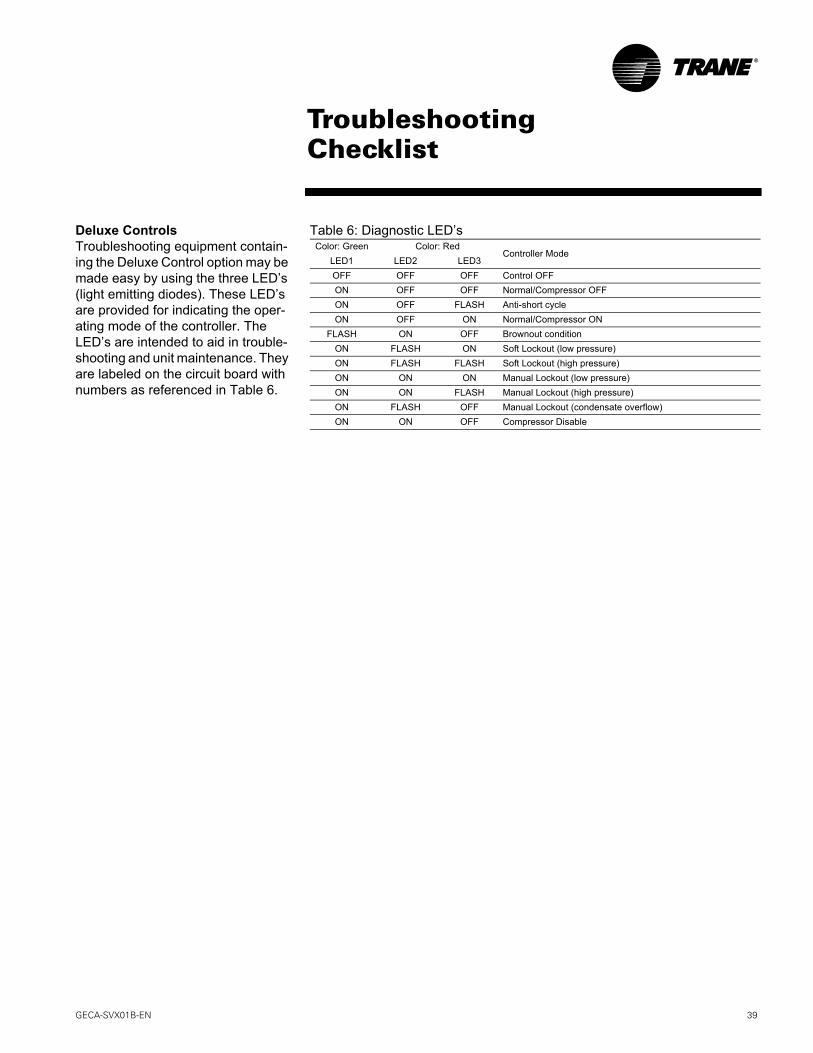
Deluxe ControlsTroubleshooting equipment contain-ing the Deluxe Control option may be made easy by using the three LED’s (light emitting diodes). These LED’s are provided for indicating the oper-ating mode of the controller. The LED’s are intended to aid in trouble-shooting and unit maintenance. They are labeled on the circuit board with numbers as referenced in Table 6.
Table 6: Diagnostic LED’sColor: Green Color: Red
Controller ModeLED1 LED2 LED3OFF OFF OFF Control OFFON OFF OFF Normal/Compressor OFFON OFF FLASH Anti-short cycleON OFF ON Normal/Compressor ON
FLASH ON OFF Brownout conditionON FLASH ON Soft Lockout (low pressure)ON FLASH FLASH Soft Lockout (high pressure)ON ON ON Manual Lockout (low pressure)ON ON FLASH Manual Lockout (high pressure)ON FLASH OFF Manual Lockout (condensate overflow)ON ON OFF Compressor Disable
TroubleshootingChecklist

40 GECA-SVX01B-EN
Unit WiringBasic
115V/60 HZ/1 PH
GECA-SVX01B-EN 41
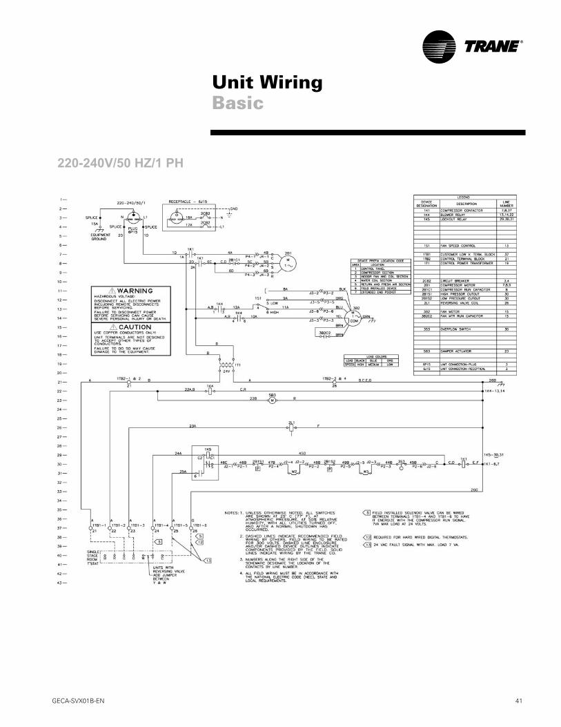
Unit WiringBasic
220-240V/50 HZ/1 PH

42 GECA-SVX01B-EN
Unit WiringDeluxe
230V/60 HZ/1 PH

GECA-SVX01B-EN 43
Unit WiringDeluxe
220-240V/50 HZ/1 PH

44 GECA-SVX01B-EN
Unit WiringTracer ZN510
265V/60 HZ/1 PH
GECA-SVX01B-EN 45
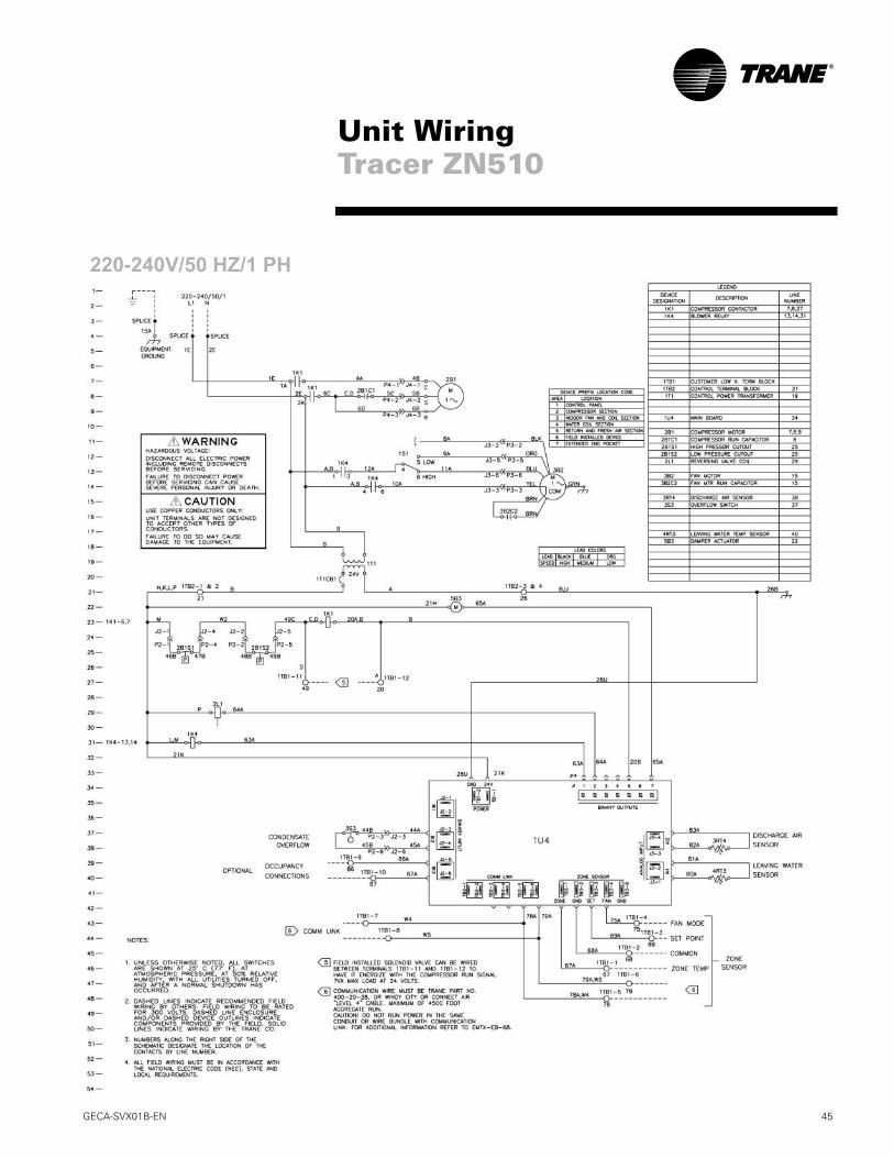
Unit WiringTracer ZN510
220-240V/50 HZ/1 PH

Trane has a policy of continuous product and data improvement and reserves the right to change design and specifications without notice.
Literature Order Number GECA-SVX01B-EN
File Number SV-UN-GECA-SVX01B-1/05
Supersedes SV-UN-GECA-SVX001-5/00
Stocking Location InlandTrane A business of American Standard Companies www.trane.com
For more information, contact your local district office or e-mail us at [email protected]