Embed Size (px)
Citation preview

I-Tork PDS Pneumatic Actuator
Installation and operating manual (PDS-M0108/1010)
I-TORK PDS PNEUMATIC ACTUATOR
1111
Installation & Operation Manual
(I-TORK PDS Series Pneumatic Actuator)
PDS-M0108/1010
74-6, Chun Ui-Dong, Won Mi-Gu, Bucheon, Kyoung Ki-Do, Korea
Tel : 82-2-855-1365, 66 Fax : 82-2-855-1367 E-mail : [email protected]
Website: www.i-tork.com

I-Tork PDS Pneumatic Actuator
Installation and operating manual (PDS-M0108/1010)
I-TORK PDS PNEUMATIC ACTUATOR
2222
Table of Contents
1. GENERAL
2. SCOTCH YOKE PRINCIPLE & ADJUSTMENT
3. IMPORTANT SAFETY PROCEDURE
4. OPERATION
5. LUBRICATION REQUIREMENTS
6. APPLICACTION
7. INSTALLATION & PIPING
8. DISMANTLE & ASSEMBLY
9. PDS50~200 PART LIST
10. TROUBLE SHOOTING
I-Tork PDS Pneumatic Actuator
Installation and operating manual (PDS-M0108/1010)
I-TORK PDS PNEUMATIC ACTUATOR
3333
Many thanks for purchasing our I-Tork PDS Pneumatic Actuator!
For safe and proper operation, please read this manual carefully before using it and save it for reference.
1. General
I-Tork PDS series actuators are designed for rotary quarter turn valves and there are
PD (Double acting) and PS (Single Acting-with Spring Pack).
I-Tork PDS series actuators can be used in the range of 4~8Kg/㎠ air supply pressure
and standard air pressure is 5.5Kg/㎠.
PD : Pmax 8 bar (116 psi)
PS : Pmax 7 bar (110 psi)
Before installation or operating actuators, please check if the specifications of the
actuator specially temperature, pressure and other site conditions are correct.
ISO Mounting Design:
ISO 5211 for valve flange or mounting bracket.
VDE 3845 (Namur) for solenoid valve.
Operating Medium:
Filtered inert gas or air must be used, and exhaust air must be passed through silencer
before being vented to the atmosphere. The dew point shall be equal to -20 °C or at
least, 10 °C below the ambient temperature (ISO8573 Part1, Class 3). The maximum
particle size shall not exceed 40 μm (ISO8573 Part1, Class 5). Max Pressure shall be
0.8 Mpa (8 bar) and the minimum design pressure for pressurized parts shall be 1.5
times the maximum operating pressure.
Important Notice: The contents in this manual are subject to change due to
quality improvement without individual notice.

I-Tork PDS Pneumatic Actuator
Installation and operating manual (PDS-M0108/1010)
I-TORK PDS PNEUMATIC ACTUATOR
4444
2. Scotch Yoke Principle & Adjustment :
I-Tork Actuators have the Scotch Yoke assembly with angled slots. Depending on the
location of the piston, torque outputs can be given different values. Scotch-Yoke technology is well known to all users as the most suitable actuator mechanism for valve
and damper operation as it produces higher torque at both the end (open and close)
positions, comparing to rack & pinion actuators. The range of ambient temperature
for standard operation is -20 ~ + 80 ℃.
I-Tork PDS is mounted standard, allowing for the highest torque at the closed position.
If the pistons in I-Tork PDS actuator are rotated 180° then the operating direction will
be switched and any adjustment will take place in both (Open & Close) positions by
turning the Adjusting Screws (23) located in the middle of the body.
Single Acting actuators have the pistons rotated 180° for a fail close position; this
means any adjustment will take place in the open position. If the SR actuator is set to
the ‘Fail Open’ position, then the adjustment will take place in the closed position. The
adjustment angle for both is ±3° by Adjusting Screws.
The adjustment occurs by loosening the Adjusting Screws of stopper in the middle of
body and I-Tork PDS have 2 Adjusting Screws for setting accurately the travel and open
and close positions.

I-Tork PDS Pneumatic Actuator
Installation and operating manual (PDS-M0108/1010)
I-TORK PDS PNEUMATIC ACTUATOR
5555
3. Important Safety Procedures
� Qualified maintenance personnel should read and follow these instructions.
� Caution: Always disconnect the Air and Electrical supplies before carrying out
any form of maintenance on an Actuator.
� Caution: When removing any ball valve or plug valve assemblies from a pipe
system, isolate the piping system on which the Actuator is installed and relieve
any media pressure that may be trapped in the valve cavities before removing
the Actuator for maintenance.
� Never attempt to ‘Blow Out’ the Pistons or the End Caps from the Actuator
Body by using air pressure.
� Never turn the adjusting screws completely out when the actuator is under
pressure.
� Do not supply air until the Pneumatic Actuator is completely mounted on the
valve installation process.

I-Tork PDS Pneumatic Actuator
Installation and operating manual (PDS-M0108/1010)
I-TORK PDS PNEUMATIC ACTUATOR
6666
4. Operation
Figure 1 : PD (Double Acting)
Close Open
When putting the air at the left port, the actuator will move to Close.
When putting the air at the right port, the actuator will move to Open.
Figure 2 : PS (Single Acting) Fail Close
Close (fail position) Open
When putting the air at the left port, the actuator will move to Open.
When the air fails, the actuator will move to the fail position (Close).
Figure 2 : PS (Single Acting) Fail Open
Close Open (fail position)
When putting the air at the left port, the actuator will move to Close.
When the air fails, the actuator will move to the fail position (Open).

I-Tork PDS Pneumatic Actuator
Installation and operating manual (PDS-M0108/1010)
I-TORK PDS PNEUMATIC ACTUATOR
7777
5. Lubrication Requirements:
I-Tork PDS generally do not require lubrication, however for performing more than
100,000 operation cycles, oil mist lubrication is recommended.
Recommended Lubrication Grease:
Parts Actuator Version Grease
Cylinder Bore, Shaft
Sealings
Standard & High
Temperature
Dark Brown Grease
ALVANIA RL2/DC111
Cylinder Bore, Shaft
Sealings
Low Temperature White Grease DC 111
(DOWCORNING)
6. Application
All quarter turn type valves and equipment like as following
1) Ball Valve(2 way, 3 way, 4 way), Screw end and flanged
2) Butterfly Valve
3) Plug Valve
4) Damper
5) etc
I-Tork PDS Pneumatic Actuator
Installation and operating manual (PDS-M0108/1010)
I-TORK PDS PNEUMATIC ACTUATOR
8888
7. Installation and piping
1) Selection of actuator
Determine the appropriate torques and strokes taking into consideration the
following parameters and questions.
- Valve Question
- Valve Manufacturer, type, size, function and operation characteristics
Operating Conditions: Media, Temperature, Pressure, Flow rate, Frequency of
operation and required stroking time.
Valve Torque Characteristics (seating/unseating, dynamic torque <when
applicable>)
Maximum Allowable Stem Torque Limitation
- Actuator Question
Motive Energy
Supply Pressure : Minimum and Maximum
Duty: On/off or Control
Acting: Double or Single (Fail Position open or close)
Frequency of operations
- Ancillary Question
Limit Switches: Type, Voltage and Local Electrical regulation
Positioners: Pneumatic or Electro-Pneumatic
Position Transmitters: Local Electrical Regulations
Solenoid Valve: Consider all actuator questions.
- Environmental Conditions
Indoor, outdoor, saline, corrosive chemicals, etc.
Enclosure Protection type
Hazardous or non-Hazardous areas
Ambient Temperature
I-Tork PDS Pneumatic Actuator
Installation and operating manual (PDS-M0108/1010)
I-TORK PDS PNEUMATIC ACTUATOR
9999
2) Installation and Mounting on the Valve
I-Tork PDS can be mounted in any position, IE: Vertical or Horizontal.
It is very important that the actuator shaft and the valve stem are centered and
must have a 0.5 ~ 1 mm gap between the actuator shaft and the valve shaft (or
driving bush) depending on the actuator size. If the actuators are not mounted
correctly, this may cause air leakage around the shaft by excess upward pressure
being exerted on the shaft seals.
Please note that the actuator has a hexagonal drive shaft and a faulty mounting of
45° can occur.
All the mounting dimensions of PDS series follows international standard as follows.
Top mounting hole : VDI/VDE3845
Top end of shaft : NAMUR for installation of Limit Switch Box or Positioner.
Bottom mounting hole: ISO5211
Bottom end of Shaft : Double Square for easy mounting (ISO5211)
3) Piping
All the actuators can be either piped with solid or flexible tubing with the solenoid
valve mounted remotely from the actuator or by mounting a NAMUR designed solenoid
valve directly onto the NAMUR mounting pad on the side of the actuator.
- Precaution
Please check the environmental conditions (Temperature, Pressure,
Characteristics of fluid, Piping standard) before piping.
And check bolts and nuts to be used in mounting.
If connection is too loose, it may cause lowering torque, shortening life cycle of
actuator. Connection of actuator is PT 1/4” for PDS 40~200.
- Solenoid valve
Since connection of actuator is PT 1/4”, please select correct size of solenoid
valve, and mounting solenoid valve on actuator, tighten the mounting bolts
strongly enough to prevent air leakage.
Don’t miss the o-ring between solenoid valve and actuator.
You may operate by manual pushing (or rotating) manual button when
emergency.

I-Tork PDS Pneumatic Actuator
Installation and operating manual (PDS-M0108/1010)
I-TORK PDS PNEUMATIC ACTUATOR
10101010
- Operating
The most important thing after piping is to supply clean and dry air into
actuator, so air filter regulator is compulsory accessory for operating.
Then, connect the electric power line to the solenoid valve, and supply electric
power. The actuator will work when there is no problem in piping.
4) Storage
Material of actuator body is Aluminum and inside and outside of actuator is
treated with hard-anodized for protection against corrosion.
But if shock comes from outside, it may cause a break of internal parts or other
damages, storage must be done with proper care.
Please don’t put heavy things on the actuator and don’t take out the plugging
cover from connection port so as for foreign material not to come inside of
actuator.
5) Manual Operation:
All the Manual operations must be carried out after venting.
To operate the actuator manually by other devices (Declutch-able Gear Box or
Hand-Wheel), it is dangerous to set free any accumulated power such as
compressed air or springs.
6) Adjusting Screw Adjustment
1. Operate Valve/Actuator assembly to the open position.
2. Remove Air supply
3. Loose lock nut on the adjusting screw
4. Turn the “Close” adjusting screw clockwise to reduce or counter clockwise to
increase the travel.
5. Tighten the lock nut.
6. Connect air and check if the position is correct. (If not, repeat from 2)
7. Operate Valve/Actuator assembly to the close position.
8. Remove Air supply
9. Adjust “Open” adjusting screw as from step 3 to 6.
I-Tork PDS Pneumatic Actuator
Installation and operating manual (PDS-M0108/1010)
I-TORK PDS PNEUMATIC ACTUATOR
11111111
8. Dismantle and Assembly
When replacing O-ring and other parts or when switching the rotating direction of
actuator, please consult I-Tork Factory in Korea first.
But when user should replace it at site, please follow the procedure for dismantle
and assembly again.
PD series (Double Acting)
1) Loose the adjusting screws (23).
2) Loose both end cover bolts (26) using Hexagonal Wrench and dismantle.
3) Using the spanner, rotate stem Pararell position with the actuator and pull out the
pistons (3) to dismantle.
4) Take the Snap Ring (21)/Washer (12)/Thrust Washer (11) out from the top of
shaft.
5) Separate the shaft(4) from the body.
� Always disconnect the air and electrical supplies before carrying out any form of
maintenance on actuator.
PS series (Single Acting)
When dismantling the Single Acting PS series, please be careful because the spring
may cause big damage to human being
1) Loose the adjusting screws(23).
2) Using hexagonal wrench, loose 2 bolts(26) in cross position on both end covers.
3) Then insert very long bolts (must be longer than length of free spring) into the 2
bolt holes which you just loose the bolts.
4) Then loose the other 2 bolts in cross position and loose above long bolts again
slowly.
5) Take out the cover(28) and spring pack (22/29/30/31/32/33).
6) Next procedure is same as PD series.
Make sure to insert long bolt after loose 2 bolts in cross position before losing
another 2 bolts in cross position.
Otherwise, spring may cause big damage to human being.

I-Tork PDS Pneumatic Actuator
Installation and operating manual (PDS-M0108/1010)
I-TORK PDS PNEUMATIC ACTUATOR
12121212
Converting PD to PS Actuators:
All I-Tork pneumatic PD (Double Acting) actuators can be converted to PS (Single
Acting) actuators by adding a spring pack as follows.
1. Please check if Air and Electrical supply are disconnected (Ensure actuator should
be de-energized)
2. Disassemble the end covers (2).
3. Loose the Adjusting screws from the body.
4. Disassemble the pistons (3).
5. Rotate the pistons (3) 180° and assemble
6. Mount Spring Pack to the body when the pistons (3) are in their inner most
position.
I-Tork PDS Pneumatic Actuator
Installation and operating manual (PDS-M0108/1010)
I-TORK PDS PNEUMATIC ACTUATOR
13131313
Disassembling of Spring Pack:
For the safe disassembling of the spring packs, the following procedure must be
carried out.
1. Please check if Air and Electrical supply are disconnected
2. Check if the springs are set free in starting position (spring is in the extended
position).
3. Loose the bolts (26) of the end cover separate Spring Pack from the body.
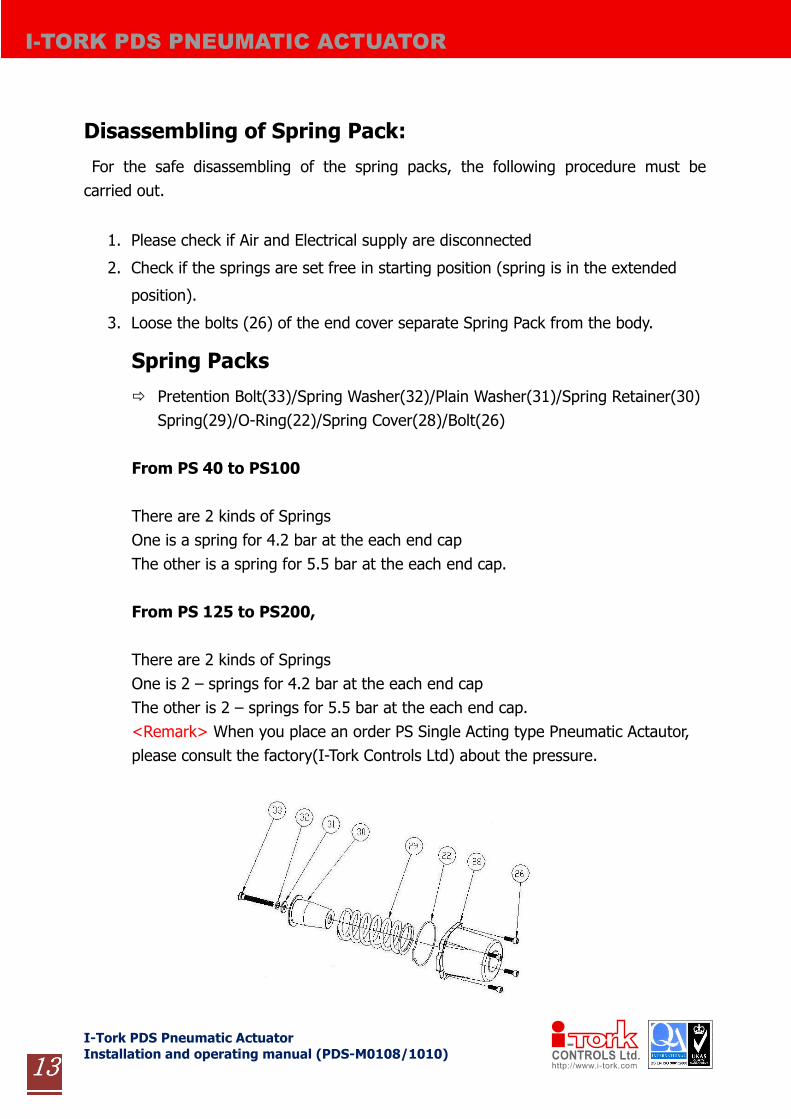
Spring Packs
� Pretention Bolt(33)/Spring Washer(32)/Plain Washer(31)/Spring Retainer(30)
Spring(29)/O-Ring(22)/Spring Cover(28)/Bolt(26)
From PS 40 to PS100
There are 2 kinds of Springs
One is a spring for 4.2 bar at the each end cap
The other is a spring for 5.5 bar at the each end cap.
From PS 125 to PS200,
There are 2 kinds of Springs
One is 2 – springs for 4.2 bar at the each end cap
The other is 2 – springs for 5.5 bar at the each end cap.
<Remark> When you place an order PS Single Acting type Pneumatic Actautor,
please consult the factory(I-Tork Controls Ltd) about the pressure.

I-Tork PDS Pneumatic Actuator
Installation and operating manual (PDS-M0108/1010)
I-TORK PDS PNEUMATIC ACTUATOR
14141414
9. PDS50~200 PART LIST
Part List No Material Part List No Material Part List No Material
1. Cylinder Aluminum 12.Washer-Shaft Steel 23. Adjust screw Steel
2. Cover Aluminum 13. Roller Pin Steel 24. NUT Stainless Steel
3. Piston Aluminum 14. Roller Steel 25. Washer-Stopper Stainless Steel
4. Shaft Steel 15. Piston Guide –
Shaft Pad
POM 26. HEX. Head
Socket Bolt
Stainless Steel
5. Scotch yoke Steel 16. Support Band PTFE 27. Set Screw Stainless Steel
6. Stopper Steel 17. O-Ring -
Piston
NBR 28. Spring
Return Cover
Aluminum
7. Shaft Wearing POM 18. O-Ring –
Shaft, lower
NBR 29. Spring Spring Steel
8. Support Ring
- Lower
POM 19. O-Ring –
Shaft - upper
NBR 30. Spring
Retainer
Steel
9. Support Ring
- Middle
POM 20. O-Ring -
Stopper
NBR 31. Plane
Washer
Steel
10. Support Ring
- Upper
POM 21. Snap Ring Stainless Steel 32. Spring
Washer
Steel
11. Thrust Washer POM 22. O-Ring- Cover Stainless Steel 33. Pretention bolt Steel

I-Tork PDS Pneumatic Actuator
Installation and operating manual (PDS-M0108/1010)
I-TORK PDS PNEUMATIC ACTUATOR
15151515
10. TROUBLE SHOOTING
Status Possible Reason Recommended action
Actuator doesn’t
work at all
Electric power line fails Check the incoming voltage
or power line
Trouble in solenoid valve
Check voltage of solenoid Coil
If coil is OK, check operation
of spool valve by using
manual button
Stuck in air supply line Check air supply line
Actuator is working,
but not very fluent
Air pressure is too low Increase supply air pressure
Stuck in air in and out lines
by foreign material
Take out foreign material in
the line
Speed controller is locked Open speed controller
Air leakage through piston
ring Replace the piston ring
Actual valve torque is too
high
1) Increase the pressure
2) Replace valve or larger
actuator
Valve doesn’t fully
open or close
Stopper setting is wrong Set stopper again
Actual valve torque is too
high
Replace valve or larger
actuator
Wrong set in speed
controller Set speed controller again
Air leakage Piston or cover bushing o-
ring worn out Replace O-rings