Embed Size (px)
Citation preview
Inst
alla
tio
n &
Op
erat
ion
Man
ual
Fo
rced
Air
Installation & Operation Manual
Engineering Specifications
GeoSource Forced Air
Models RGS-V024 – RGS-V072
Models RGT-V024 – RGT-V072

1
This Page Intentionally Left Blank
2
Table of Contents
I. Key & Legend ................................................................................................................................................................... 3 Key to Model Numbers ....................................................................................................................................................... 3 Configuration Options ......................................................................................................................................................... 4 Legend for Tables ................................................................................................................................................................ 4
II. Warnings & Cautions ....................................................................................................................................................... 5 III. General Information ................................................................................................................................................... 5
Inspection ............................................................................................................................................................................ 5 Storage ................................................................................................................................................................................ 5 Protection ............................................................................................................................................................................ 6 Pre-Installation Preparation ................................................................................................................................................ 6
IV. Best Practices .............................................................................................................................................................. 6 System Sizing ....................................................................................................................................................................... 6
Building Heat Loss/Heat Gain .......................................................................................................................................... 6 Ground Sources and Design Water Temperatures .......................................................................................................... 6 Temperature limitations .................................................................................................................................................. 7
V. System Design .................................................................................................................................................................. 7 Ground Source Design ......................................................................................................................................................... 7
Ground Loop Installation ................................................................................................................................................. 7 Ground Water Installation ............................................................................................................................................... 8
Application Diagrams .......................................................................................................................................................... 9 Unit Location/Mounting ...................................................................................................................................................... 9
VI. Electrical ...................................................................................................................................................................... 9 Controller .......................................................................................................................................................................... 10 LED Lights .......................................................................................................................................................................... 12
VII. Heat Pump Commissioning ....................................................................................................................................... 13 Maintenance ..................................................................................................................................................................... 14
VIII. Accessories ................................................................................................................................................................ 14 Room Thermostat.............................................................................................................................................................. 14 Desuperheater ................................................................................................................................................................... 14
IX. Engineering Specifications ........................................................................................................................................ 17 Performance Ratings ......................................................................................................................................................... 17 Performance Data ............................................................................................................................................................. 22 Physical Dimensions .......................................................................................................................................................... 27 Electrical Data .................................................................................................................................................................... 29
Single Stage Models with PSC Blower Motor ................................................................................................................ 29 Single Stage Models with ECM Blower Motor ............................................................................................................... 29 Two Stage Models with ECM Blower Motor.................................................................................................................. 29
Wiring Diagram .................................................................................................................................................................. 30 Water Coil Pressure Drop Ratings ..................................................................................................................................... 32 Correction Factors ............................................................................................................................................................. 32 Blower Performance.......................................................................................................................................................... 33
X. Figures ............................................................................................................................................................................ 34 XI. Troubleshooting ........................................................................................................................................................ 36
3
I. KEY & LEGEND
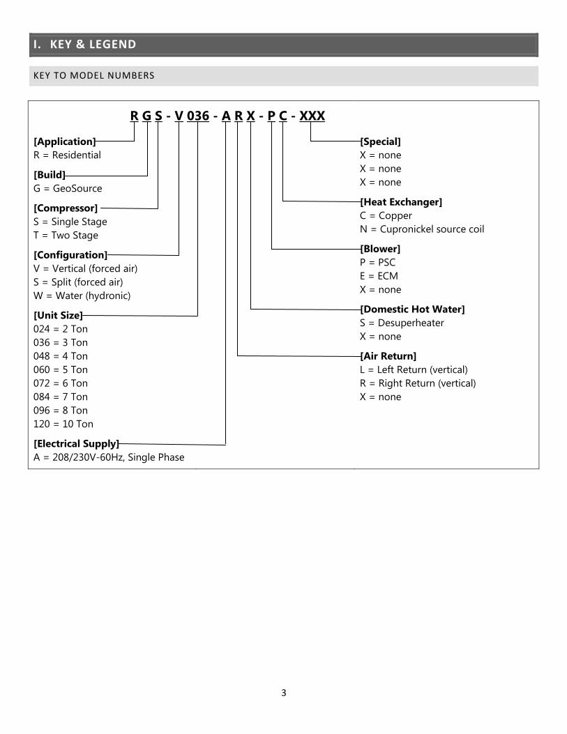
KEY TO MODEL NUMBERS
R G S - V 036 - A R X - P C - XXX
[Application]
R = Residential
[Build]
G = GeoSource
[Compressor]
S = Single Stage
T = Two Stage
[Configuration]
V = Vertical (forced air)
S = Split (forced air)
W = Water (hydronic)
[Unit Size]
024 = 2 Ton
036 = 3 Ton
048 = 4 Ton
060 = 5 Ton
072 = 6 Ton
084 = 7 Ton
096 = 8 Ton
120 = 10 Ton
[Electrical Supply]
A = 208/230V-60Hz, Single Phase
[Special]
X = none
X = none
X = none
[Heat Exchanger]
C = Copper
N = Cupronickel source coil
[Blower]
P = PSC
E = ECM
X = none
[Domestic Hot Water]
S = Desuperheater
X = none
[Air Return]
L = Left Return (vertical)
R = Right Return (vertical)
X = none

4
CONFIGURATION OPTIONS
Standard Special Order - Not Available
Model Suffix Description 036 048 060 072
RGS – **** - *** - ** - *** Single stage compressor
RGT – **** - *** - ** - *** Two stage compressor
RG* – **** - A** - ** - *** 208/230-1, 60 Hz
RG* – V*** - *L* - ** - *** Left return
RG* – V*** - *R* - ** - *** Right return
RG* – **** - **X - ** - *** No Desuperheater
RG* – **** - **S - ** - *** Desuperheater
RGS – V*** - *** - P* - *** PSC Blower
RGS – V*** - *** - E* - *** ECM Blower
RGT – V*** - *** - E* - *** ECM Blower
RG* – **** - *** - *C - *** Standard, Copper
RG* – **** - *** - *N - *** Cupronickel source coil
LEGEND FOR TABLES
BTU/hr Heating or cooling capacity GPM Gallons Per Minute
CAP Capacity HE Heat Extracted
COP Coefficient of performance (BTU/hr out : BTU/hr in) HR Heat Rejected
CFM Cubic feet per minute HYD Hydronic
DB Dry-bulb entering air temperature kW Kilowatt
DEWT Demand Entering Water Temperature LLTC Liquid Line Temperature Cooling
DHW Demand Hot Water LLTH Liquid Line Temperature Heating
DLWT Demand Leaving Water Temperature LRA Locked-rotor amperage
dP Pressure drop across heat pump LWT Leaving water temperature
DSH Desuperheater MBTU/hr Btu/hr x 1000
EER Energy efficient ratio (BTU/hr CAP : watts in) RLA Rated-load amperage
EWT Entering water temperature SLT Suction Line Temperature
FLA Full-load amperage VA Volt-amperes
GND Ground WB Wet-bulb entering air temperature
5
II. WARNINGS & CAUTIONS
Note – Always refer to the inside of the lower
front door for the correct wiring diagram, and
always refer to the nameplate on the exterior of the
cabinet for the correct electrical specifications.
WARNING – Service of refrigerant-based
equipment can be hazardous due to elevated
system pressures and hazardous voltages. Only
trained and qualified personnel should install,
repair or service. Installer is responsible to ensure
that all local electrical, plumbing, heating and air
conditioning codes are followed.
WARNING – ELECTRICAL SHOCK CAN
CAUSE PERSONAL INJURY OR DEATH.
Disconnect all power supplies before installing or
servicing electrical devices. Only trained and
qualified personnel should install, repair or service
this equipment.
WARNING – THE UNIT MUST BE PROPERLY
GROUNDED!
The main electrical service must be protected by a
fuse or circuit breaker and be capable of providing
the amperes required by the unit at nameplate
voltage. All wiring must comply with the national
electrical code and/or any local codes that may
apply. Access to the line voltage contactor is
through the knockouts provided on the side of the
heat pump as labeled. Route EMT or flexible
conduit with appropriate size and type of wire.
Ensure adequate supply wiring to minimize the
level of dimming lights during compressor startup
on single-phase installations. Some dimming is
normal upon compressor start-up.
CAUTION – Route field electrical wiring to
avoid contact with electrically live bare metal parts
inside the electrical box.
CAUTION – Three-phase units must be wired
properly to ensure proper compressor rotation.
Improper rotation may result in compressor
damage. An electronic phase sequence indicator
must be used to check supply-wiring phases.
Also, the “Wild” leg of the three-phase power must
be connected to the middle leg on the contactor.
WARNING –Verify refrigerant type before
servicing. The nameplate on the heat pump
identifies the type and the amount of refrigerant.
All refrigerant removed from these units must be
reclaimed by following accepted industry and
agency procedures.
CAUTION – Ground loop must be freeze
protected. Insufficient amounts of antifreeze may
cause severe damage and will void warranty. Loop
antifreeze must be non-flammable. Never operate
with ground loop flow rates less than specified.
Continuous operation at low flow or no flow may
cause severe damage and may void warranty.
III. GENERAL INFORMATION
INSPECTION
Equipment should be inspected upon receipt to
assure that damage has not occurred during
shipment of the unit. Carefully check the shipping
company bill of lading against the packing slip to
verify that all units and accessory packages have
been received. Inspect each package for physical
damage and ensure that the carrier makes notation
of any damage or missing packages on bill of
lading records. Pictures of any damage are
recommended. Concealed damage should be
reported to the shipping company immediately.
STORAGE
Unit should be stored in a clean, dry location in the
original shipping packaging. Units shall be stored
in an upright position and should not be stacked
unless noted on the shipping packaging.
6
PROTECTION
Units should be protected when on the building
site from damage and contamination. Keep units
covered or in original shipping packaging during
job site construction. All physical connections (air
supply and return, piping, electrical) should be
protected and covered/capped prior to installation.
PRE-INSTALLATION PREPARATION
Care should be taken to assure that the installation
of the geothermal unit is successful. Locate the unit
where there is adequate ventilation and room for
servicing. Units should be placed on a level surface
on a vibration–absorbing pad slightly larger than
the base of the unit. Care should be taken to use
the proper duct size, piping is not hard-plumbed to
the unit, and any sound or vibration is not
transmitted into the surroundings.
Units are designed for indoor installation only
where the ambient temperature remains above
45°F. Do not use the heat pump for initial heating
of the building during construction. Operating the
heat pump during construction or renovation will
subject the unit to contamination, potentially
resulting in failure of the unit. Starting the heat
pump in a cold environment may flush lubricant
from the compressor resulting in compressor damage
and ultimately, unit failure.
Review the electrical data on the nameplate to
assure that the correct unit has been shipped
Carefully remove any packing material from
the outside and inside of the unit and inspect
for any concealed damage
Inspect electrical connections for cleanliness
and attachment
Inspect liquid connections to assure that any
debris has been removed and caps are removed
as appropriate.
IV.BEST PRACTICES
SYSTEM SIZING
Selecting the unit capacity of a geothermal heat
pump requires three things:
Building Heat Loss / Heat Gain.
Ground Sources and Design Water Temperatures.
Temperature Limitations.
BUILDING HEAT LOSS/HEAT GAIN
The space load must be estimated accurately for
any successful HVAC installation. There are many
guides or computer programs available for
estimating heat loss and gain, including the
Manual J, and others. After the heat loss and gain
analysis is completed, Entering Water
Temperatures (EWT’s) are established, and heating
conditions are determined. The heat pump can now
be selected using the heat pump data found in the
Engineering Specifications section. Choose the
capacity of the heat pump based on both heating
and cooling loads.
GROUND SOURCES AND DESIGN WATER
TEMPERATURES
Ground sources include the Ground Water
(typically a well) and the Ground Loop varieties.
Water flow-rate requirements vary based on
configuration. The Engineering Specifications section
provides capacities at different loop entering water
temperatures and entering air temperatures.
GROUND LOOP SYSTEMS
Loop systems use high-density polyethylene pipe
buried underground to supply a tempered water
solution back to the heat pump. Ground loops
operate at higher flow rates than ground water

7
systems because the loop Entering Water
Temperature (EWT) is lower. EWT affects the
capacity of the unit in both heating and cooling
modes, and loops in cold climates are normally
sized to supply wintertime EWT to the heat pump
down to 25°F.
GROUND WATER SYSTEMS
See Figure 3
Note – If a heat pump is installed with ground
water, it should have a Cupro-Nickel (CuNi) water
coil. Cupro-Nickel water coils withstand well water
much better than standard copper water coils.
TEMPERATURE LIMITATIONS
Be aware of the operating range of the geothermal
system when sizing the particular heat pump to
avoid premature equipment failure. Operating
outside of these limitations may cause severe
damage to the equipment and may void warranty.
CAUTIONS: Reference tables in section XI for
acceptable operating conditions.
V. SYSTEM DESIGN
GROUND SOURCE DESIGN
GROUND LOOP INSTALLATION
A Ground Loop system circulates the same
antifreeze solution through a closed system of
high-density underground polyethylene pipe. As
the solution passes through the pipe, it collects
energy (in the heating mode) from the relatively
warm surrounding soil through the pipe and into
the relatively cold solution. The solution circulates
to the heat pump, which transfers energy with the
solution, and then the solution circulates back
through the ground to extract more energy.
CAUTION – Ground Loops must be properly
freeze protected. Insufficient amounts of antifreeze
may result in a freeze rupture of the unit or can
cause unit shutdown problems during cold
weather operation. Propylene glycol is a common
antifreeze solution. Propylene glycol antifreeze
solution should be mixed 25% with water to obtain
a 15°F freeze protection. Enertech proprietary
Geothermal Transfer Fluid (GTF) is methanol-
based antifreeze and should be mixed 50% with
water to achieve freeze protection of 12°F.
Important – Do not mix more than 25%
propylene glycol with water in an attempt to
achieve lower than 15°F freeze protection, since
more concentrated mixtures of propylene glycol
become too viscous at low temperatures and will
become more difficult to pump through the earth
loop. Horizontal loops typically use GTF, and
vertical loops typically use propylene glycol.
Note – Always check State and Local codes for any
special requirements on antifreeze solutions.
CAUTION – Never operate with flow rates less
than specified. Low flow or no flow, may cause the
unit to shut down on a pressure lockout or may
cause a freeze rupture of the heat exchanger.
Important– Installation of Pressure/Temperature
(P/T) ports in the entering and leaving water lines
of the heat pump is recommended (see figure 2). A
thermometer can be inserted into the P/T ports to
check entering and leaving water temperatures. A
pressure gauge can also be inserted into these P/T
ports to determine the pressure differential
between the entering and leaving water. This
pressure differential can then be compared to the
specification data on each particular heat pump to
confirm the proper flow rate of the system.
An individually-sized Enertech flow center can
supply pumping requirements for the Ground
Loop fluid.
8
Note – Refer to instructions included with the
flow center for properly purging the ground loop.
Filling and purging a loop system are very
important steps to ensure proper heat pump
operation. Each loop must be purged with enough
flow to ensure two feet per second flow rate in each
circuit in the loop. This normally requires a 1½ to 3
HP high-head pump to circulate fluid through the
loop to remove all the air out of the loop. Allow the
pump to run 10 to 15 minutes after the last air
bubbles have been removed. After purging is
completed, add the calculated proper amount of
antifreeze to give a 12°F to 15°F freeze
protection. Always pump away from coil or into
the earth loop. After antifreeze has been installed
and thoroughly circulated, it should be measured
with a hydrometer (methanol), refractometer
(propylene glycol), or GeoSystems methanol anti-
freeze tester to determine the actual freezing point
of the solution.
The purge pump can be used to pressurize the
system for a final static pressure of 30-40 psig after
the loop pipe has had enough time to stretch. In
order to achieve the 30 to 40 psig final pressure, the
loop may need to be initially pressurized to 60-65
psig. This static pressure may vary 10 psig from
heating to cooling season, but the pressure should
always remain above 20 psig, to ensure circulation
pumps do not cavitate or pull air into the system.
Contact your local installer, distributor or factory
representative for more information.
GROUND WATER INSTALLATION
Since water is the source of energy in the winter
and the energy sink in the summer, a good water
supply is possibly the most important requirement
of a geothermal heat pump system installation.
A Ground Water system gets its name from the
open discharge of water after it has been used by
the heat pump. A well must be available that can
supply all of the water requirements of the heat
pump for up to 24 hours/day on the coldest winter
day plus any other water requirements drawing
off of that same well. A bladder type pressure tank
with a “draw down” of at least 1 ½ times the well
pump capacity must be installed on the supply side
of the heat pump.
Important – A screen strainer must be placed on
the supply line with a mesh size of 40 or 60 and
enough surface area to allow for particle buildup
between cleanings.
Important – It is highly recommended that
Pressure/Temperature (P/T) ports be placed in the
supply and discharge lines so that thermometers or
pressure gauges can be inserted into the water
stream.
Important – It is highly recommended that a
visual flow meter be installed to allow visual
inspection of the flow. If flow meter appears cloudy
the water coil may need to be cleaned.
A solenoid control valve must be installed on the
water discharge side of the heat pump to regulate
the flow through the unit.
Schedule 40 PVC piping, copper tubing,
polyethylene or rubber hose can be used for supply
and discharge water lines. Make sure line sizes are
large enough to supply the required flow with a
reasonable pressure drop (generally 1” diameter
minimum). Consult local plumbing codes to ensure
compliance.
CAUTION – Never operate with flow rates less
than specified. Low flow rates, or no flow, may
cause the unit to shut down on a pressure lockout
or may cause a freeze rupture of the heat
exchanger. If unit is operated without flow
warranty with be voided.
9
GROUND WATER FREEZE PROTECTION
CAUTION – Only equipment ordered with a
CuNi coil shall be used on ground water
applications. These units are provided with freeze
protection.
APPLICATION DIAGRAMS
Figures 1 through 4, show the components of a heat
pump system discussed above used in some
common applications. These figures by no means
represent all the possible heat pump applications,
but they do show important principles that can be
applied to any system.
UNIT LOCATION/MOUNTING
CAUTION – Units must be kept in an upright
position during transportation or installation, or
severe internal damage may occur. Never
transport a heat pump on its side or back.
CAUTION – Do not use this unit during
construction. Dust and debris may contaminate
electrical and mechanical components; resulting in
damage.
Important – To ensure easy removal and
replacement of access panels, leave panels secured
in place until the unit is set in place and leveled.
Important – Locate the unit indoors where
ambient temperature remains above 45°F. Service is
primarily from the front. Rear and side access
should be provided when possible, 12” clearance
on all sides is desirable.
Important – A field installed drain pan is
required under the entire unit if accidental water
discharge could damage surrounding floors, walls
or ceilings. Check local codes for compliance.
CAUTION – Do not mount components or pipe
to the exterior of the heat pump cabinet.
Important – Units must be mounted on a
vibration absorbing pad slightly larger than the
base to provide isolation between unit and floor.
Water supply pumps shall not be hard plumbed
directly to the unit with copper pipe; this could
transfer vibration from the water pump to the
refrigeration circuit, causing a resonating sound.
Flexible water connection use is recommended to
eliminate transfer of vibration wherever possible.
CAUTION – Always use plastic male fittings
into plastic female or into metal female fittings.
Never use metal male fittings into plastic female
fittings. On metal-to-metal fittings; use pipe thread
compound, do not use pipe thread tape. Hand
tighten first, then only tighten an additional ½ turn
with a tool if necessary. On plastic fittings, always
use 2 to 3 wraps of pipe thread tape, do not use
pipe thread compound. Hand tighten first, then
only an additional ½ turn with a tool if necessary.
Do not over-tighten, as damage may occur.
Important – Install a P-trap in condensation line,
unit is not internally equipped with one. Trap
outlet bottom must be at least 1/2 inch below drain
pan bottom to ensure a proper drainage slope.
Prevent pressure lock within the drain line, by
installing with constant downward slope.
VI. ELECTRICAL
Note – Always refer to the inside of the front panel
for the correct wiring diagram.
Important – If external controls require more power
than shown in the engineering specification, external
transformer & isolation relays should be used.
Important – Miswiring of 24Vac control voltage
on system controls can result in transformer
burnout.
10
Important – Units with dual voltage rating
(example, 208/230) are factory-wired for the higher
voltage (example, 230). If connected to power
supply having the lower voltage, change wiring to
transformer primary to the correct lead; otherwise
premature failure, or inability to operate the control
components may occur.
CONTROLLER
The controller is designed to provide high
reliability in controlling numerous operating
functions of geothermal heat pumps with space
heating, space cooling, desuperheater and
dedicated domestic water heating. This controller
switches control devices by reviewing the various
control inputs and temperature information,
making decisions based on operation priority.
Power up Initialization
When system powers up, there is a random start up
time of 30-90 seconds. Once per second, the
controller will examine process inputs, execute the
control algorithm for the system, and update the
process outputs.
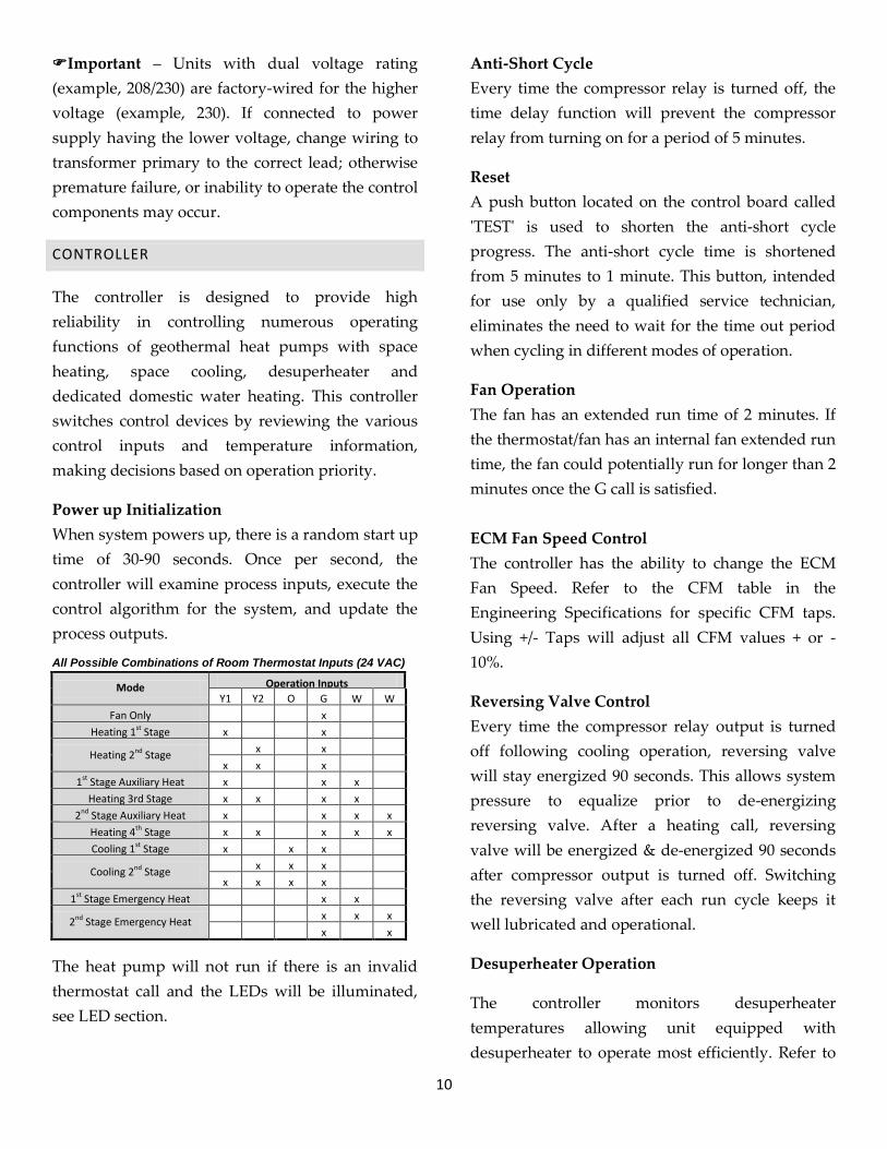
All Possible Combinations of Room Thermostat Inputs (24 VAC)
Mode Operation Inputs
Y1 Y2 O G W1
W2 Fan Only x
Heating 1st Stage x x
Heating 2nd Stage x x
x x x
1st Stage Auxiliary Heat x x x
Heating 3rd Stage x x x x
2nd Stage Auxiliary Heat x x x x
Heating 4th Stage x x x x x
Cooling 1st Stage x x x
Cooling 2nd Stage x x x
x x x x
1st Stage Emergency Heat x x
2nd Stage Emergency Heat x x x
x x
The heat pump will not run if there is an invalid
thermostat call and the LEDs will be illuminated,
see LED section.
Anti-Short Cycle
Every time the compressor relay is turned off, the
time delay function will prevent the compressor
relay from turning on for a period of 5 minutes.
Reset
A push button located on the control board called
'TEST' is used to shorten the anti-short cycle
progress. The anti-short cycle time is shortened
from 5 minutes to 1 minute. This button, intended
for use only by a qualified service technician,
eliminates the need to wait for the time out period
when cycling in different modes of operation.
Fan Operation
The fan has an extended run time of 2 minutes. If
the thermostat/fan has an internal fan extended run
time, the fan could potentially run for longer than 2
minutes once the G call is satisfied.
ECM Fan Speed Control
The controller has the ability to change the ECM
Fan Speed. Refer to the CFM table in the
Engineering Specifications for specific CFM taps.
Using +/- Taps will adjust all CFM values + or -
10%.
Reversing Valve Control
Every time the compressor relay output is turned
off following cooling operation, reversing valve
will stay energized 90 seconds. This allows system
pressure to equalize prior to de-energizing
reversing valve. After a heating call, reversing
valve will be energized & de-energized 90 seconds
after compressor output is turned off. Switching
the reversing valve after each run cycle keeps it
well lubricated and operational.
Desuperheater Operation
The controller monitors desuperheater
temperatures allowing unit equipped with
desuperheater to operate most efficiently. Refer to

11
the Desuperheater section for more information
about Desuperheater controls.
Dip Switches
The dip switches mounted on the controller board
allow the installer to select various features for
operating the unit. Once the dip switch position is
changed, power must be reset in order for the
change to register on the control board.
The dip switches are listed below.
Main Board
Designator Description Dipswitch On Dipswitch
Off
FRZ Freeze Protection 15°F 33°F
STG2
Single or Two Stage Compressor
Two Stage Single Stage
DSH Enable/Disable Desuperheater
Enabled Disabled
PMP Loop Pumps Together Separate1
HYD2
Water-to-Water or Water-to-Air
Water-to-Water
Water-to-Air
1 See Ground Loop Pump operation for more information. 2 Used for internal software to verify board configuration w/model number.
Demand Hot Water Board
Designator Description Dipswitch On Dipswitch Off
ENB Enable/Disable
Hot Water Enabled Disabled
PRT Priority (DHW or
Thermostat) DHW has Priority
1
Thermostat has Priority
SMP Hot Water
Sampling Rate Continuous Sample
Explanation of Dip Switch Settings
SMP - Sampling Mode
In the OFF position, this selection commands the
hot water circulating pump to turn on every five
minutes to circulate water from the hot water
storage tank to the heat pump. At the end of a 2
minute period (sampling of the water temperature),
if the temperature of the water entering the heat
pump is equal to or less than the programmed cut-
in temperature after 2 minutes of continuous
circulation, water heating mode is initiated.
In the ON position, the pump will run
continuously, similarly the water will be sampled
continuously. See priority settings & operation for
more information.
STG-Ground Loop Pump Operation
Water circulating pumps used to circulate an
antifreeze solution can be staged by the controller
to cycle on one or more pumps at different entering
water temperatures.
Loop pump relay #1 is the primary pump control. It
is energized whenever there is a call for space
heating, space cooling, and water heating.
Staging Control
In the space heating mode, as fluid temperature
declines in the winter, more flow (gpm) is required
to provide more heat transfer from the ground to
the heat pump. Likewise, in the space cooling
mode, as fluid temperature increases, more flow
(gpm) is required to remove heat from the heat
pump to the ground.
Energy savings are increased because the heat
pump can cycle off one or more pumps when they
are not needed.
Heating Operation (Thermostat or DHW)
Ground loop pump #2 will turn on once the
entering water temperature falls below 60°F. Pump
#2 will turn off once the temperature rises to 65° F.
Pump #2 will turn on/off “on the fly”. EWT is
continually checked during operation.
Cooling Operation
Ground loop pump #2 will turn on once the
entering water temperature rises above 60°F. Pump
#2 will turn off once the temperature falls to 55° F.
Pump #2 will turn on/off “on the fly”. EWT is
continually checked during operation.
12
LED LIGHTS
PWR LED
Solid illumination of this light indicates that the
control board is functioning properly. During the
random start period the LED will be flashing. No
light may indicate loss of power to board. Voltage
must be 18VA - 32VA.
Mode of Operation LED Lights
Mode of Operation LED lights (three) in addition to
the PWR LED, aid in troubleshooting and
indicating the mode of operation. While a mode is
running the LED will be illuminated solid. If a
mode is waiting to run for the anti-short cycle
period the LED will be flashing.
Heating - Space Heating or Electric Heat Operation
Cooling - Space Cooling Operation
Demand Hot Water - Demand Hot Water
Operation (will not illuminate if Desuperheater running)
Service LED Lights
Service LED lights (five) in addition to the PWR
and Mode LEDs, aid in troubleshooting. They are
as follows:
High DGT - Hot refrigerant gas
High Pressure - Excessive refrigerant pressure
Low Pressure - Refrigerant pressure too low
Freeze - LWT below setpoint
Overflow - Drain pan filled with water
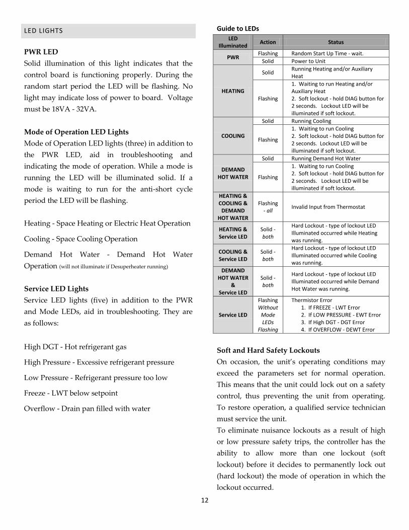
Guide to LEDs
LED Illuminated
Action Status
PWR Flashing Random Start Up Time - wait.
Solid Power to Unit
HEATING
Solid Running Heating and/or Auxiliary Heat
Flashing
1. Waiting to run Heating and/or Auxiliary Heat 2. Soft lockout - hold DIAG button for 2 seconds. Lockout LED will be illuminated if soft lockout.
COOLING
Solid Running Cooling
Flashing
1. Waiting to run Cooling 2. Soft lockout - hold DIAG button for 2 seconds. Lockout LED will be illuminated if soft lockout.
DEMAND HOT WATER
Solid Running Demand Hot Water
Flashing
1. Waiting to run Cooling 2. Soft lockout - hold DIAG button for 2 seconds. Lockout LED will be illuminated if soft lockout.
HEATING & COOLING &
DEMAND HOT WATER
Flashing - all
Invalid Input from Thermostat
HEATING & Service LED
Solid - both
Hard Lockout - type of lockout LED Illuminated occurred while Heating was running.
COOLING & Service LED
Solid - both
Hard Lockout - type of lockout LED Illuminated occurred while Cooling was running.
DEMAND HOT WATER
& Service LED
Solid - both
Hard Lockout - type of lockout LED Illuminated occurred while Demand Hot Water was running.
Service LED
Flashing Without
Mode LEDs
Flashing
Thermistor Error 1. If FREEZE - LWT Error 2. If LOW PRESSURE - EWT Error 3. If High DGT - DGT Error 4. If OVERFLOW - DEWT Error
Soft and Hard Safety Lockouts
On occasion, the unit’s operating conditions may
exceed the parameters set for normal operation.
This means that the unit could lock out on a safety
control, thus preventing the unit from operating.
To restore operation, a qualified service technician
must service the unit.
To eliminate nuisance lockouts as a result of high
or low pressure safety trips, the controller has the
ability to allow more than one lockout (soft
lockout) before it decides to permanently lock out
(hard lockout) the mode of operation in which the
lockout occurred.

13
For example, when the high pressure lockout
occurs in heating mode for the third time in a
period less than 90 minutes, the heating mode will
be disabled until a manual reset is performed.
High & Low Pressure Lockout
The High or Low Pressure LED is illuminated once
a Hard Lockout occurs. A hard lockout is defined
as; high or low pressure switch has been activated 3
times within 90 minutes. Once the high or low
pressure switch is activated, the unit is shut down
and soft lockout is triggered. The unit will be shut
down for 15 minutes. At which time it will attempt
to run again if there is a thermostat input. If a hard
lockout occurs power must be reset in order to
clear the lockout.
Discharge Gas Temperature (DGT) Lockout
The discharge gas refrigerant temperature is
continually monitored and when hot gas
temperature rises above 250°F a soft lockout is
initiated and the unit is shut down. Unit will be
shut down for 15 minutes, at which time it will
attempt to run again if there is a thermostat input
and the DGT temperature is below 200°F. If DGT
reaches 250°F 3 times in a 90 minute period a hard
lockout will be set requiring a manual power reset.
Overflow Lockout
Once the overflow sensor is triggered a hard
lockout will be set requiring a manual power reset.
Freeze Lockout
Freeze protection lockout occurs when the leaving
water temperature falls below the setpoint of LWT.
At which time a soft lockout is initiated and the
compressor is shut down. The ground loop pump
remains on for 15 minutes. The unit will attempt to
run again if there is a thermostat input and the
LWT rises 7°F above setpoint.
If a freeze lockout is initiated 3 times in a 90 minute
period a hard lockout will be set requiring a
manual power reset.
Active Control Panel
All LED lights are also located on the Membrane.
The TEST button is located on the membrane at the
top left corner or on the left below the service
LEDs. The DIAG button is located on the
membrane at the top right corner or on the right
below the “t” in GeoSystems. Refer to GeoSource
controller manual for further information.
VII. HEAT PUMP COMMISSIONING
Before applying power to the heat pump, check the
following items:
Water supply plumbing to the heat pump is
completed and operating. Manually open the
water valve on well systems to check flow.
Make sure all valves are open and air has been
purged from a loop system. Never operate the
system without correct water supply flow.
All high voltage and all low voltage wiring is
correct and checked out, including wire sizes,
fuses and breakers. Set system to the “OFF”
position.
Note – the heat pump is located in a warm area
(above 45°F). (Starting the system with low
ambient temperature conditions is more
difficult and may cause low-pressure lockout.)
Do not leave the area until the space is brought
up to operating temperatures.
Commissioning
The controller has the ability to perform a system
check on all modes using the Commissioning
process.
14
Run this process at the end of each installation -
data will be stored in the controller.
1. Reset Power.
2. Hold the TEST button for 10 seconds. PWR
& Cooling LED will begin flashing.
3. Cooling will be run for 15 minutes.
4. Unit idle for 3 minutes while Heating LED
flashing.
5. Heating will be run for 15 minutes.
6. Unit idle for 3 minutes.
7. If equipped with DHW and/or
Desuperheater - the DHW or Desuperheater
will run for 15 minutes. Unit will run
Heating while running Desuperheater.
8. Once complete the following LEDs will be
illuminated:
a. Power – Off
b. Heating – On
c. Cooling - On
d. Demand Hot Water – On
9. Hold TEST button for 2 seconds or power
reset to resume normal operation.
Note – 1st successful commissioning data is
stored permanently.
MAINTENANCE
Properly installed, the Enertech GeoSource heat
pump requires only minor maintenance such as
periodic cleaning of the ground water heat
exchanger for heat pumps installed in ground-
water applications. Setting up regular service
checkups with your Enertech dealer should be
considered. Any major problems with the heat
pump system operation will be indicated on the
lockout lights.
CAUTION – During evacuation of refrigerant of
a system not having antifreeze protection of the
ground-side, water in the unprotected heat
exchanger must be removed or continuously
flowing to avoid a potential heat exchanger failure
caused by freeze rupture.
Important – Always install a new filter/drier
after replacing a refrigeration component
(compressor, etc.).
The GeoSource controller (and a room thermostat,
if part of the system installation) will display a
system lockout. If lockout occurs, follow the
procedure below:
1. Determine and record which indicator lights on
the controller are illuminated. (Refer to
Troubleshooting Section for more information
on possible causes of Lockout Conditions.)
2. Check for correct water supply from the ground
loop or ground water system.
3. Reset the system by disconnecting power at the
circuit breaker for one minute and then
reapplying.
4. If shutdown reoccurs, Call your Enertech
dealer. Do not continuously reset the lockout
condition or serious damage may occur.
Note – Improper fluid flows or incorrect
antifreeze levels are the cause of almost all
lockouts.
VIII. ACCESSORIES
ROOM THERMOSTAT
Installations may include a wide variation of
available electronic room thermostats, and most of
them must be configured by the Installer and
checked out after installation. For the number of
wires required or other questions, please refer to
the installation manual that was sent with the
thermostat.
DESUPERHEATER
A heat pump equipped with a double-wall vented
15
desuperheater can provide supplemental heating of
domestic hot water by stripping some energy from
the superheated gas leaving the compressor and
transferring it to a hot water tank. A built in
desuperheater pump circulates water from the
domestic hot water tank, heats it and returns it to
the tank.
The desuperheater only provides supplemental hot
water when the compressor is running to condition
space. Because the desuperheater is using some
energy from the heat pump to heat water, the heat
pump’s capacity in the winter is about 10% less
than a unit without a desuperheater. The
desuperheater can be disabled with a dip switch on
the control board.
The GeoSource control board has the ability to
control desuperheater operation. The
desuperheater will operate once the entering
desuperheater temperature is below 120°F and the
compressor is energized. The desuperheater will
continue to run until the DEWT reaches 130°F, at
which point operation will end.
Desuperheater operation is ended once an auxiliary
heat call is made.
The desuperheater can be enabled or disabled with
a dipswitch on the control board. Refer to Control
Section.
WARNING–The desuperheater high temperature
cutout switch is located on the return line from the
water heater and is wired in series with the
desuperheater pump to disable it from circulating
at entering water temperatures above 140°F. If tank
temperatures become uncomfortably hot, move this
switch to the leaving water line, which will reduce
the tank maximum temperatures 10°F to 15°F.
CAUTION– Running desuperheater pump
without water flow will damage the pump. A fuse
is attached to the fuse holder and must be
inserted in the fuse holder after the desuperheater
is purged and operational.
Important – Do not insert the fuse until water
flow is available and the desuperheater is
completely purged of air, or the pump may be
damaged.
All air must be purged from the desuperheater
plumbing before the pump is engaged. To purge
small amounts of air from the lines, loosen the
desuperheater pump from its housing by turning
the brass collar. Let water drip out of the housing
until flow is established, and re-tighten the brass
collar. Using 1/2-inch copper tubing or larger from
the tank to the desuperheater inlet is recommended
to allow proper water flow. An air vent in the inlet
line can also help systems where air is a problem. If
one is used, mount it near the desuperheater inlet
roughly 2-1/2 inches above the horizontal pipe.
Shutoff valves allow access to the desuperheater
plumbing without draining the hot water tank.
Keep the valves open when the pump is running.
Hot water tank maintenance includes periodically
opening the drain on the hot water tank to remove
deposits. If hard water, scale, or buildup causes
regular problems in hot water tanks in your area, it
may result in a loss of desuperheater effectiveness.
Cleaning may be required.
CAUTION – Insulated copper tubing must be
used to run from the water tank to the
desuperheater connections on the side of the unit.
Desuperheater must be plumbed in copper tubing.
The built-in desuperheater pump can provide the
proper flow to the desuperheater if the total
equivalent length of straight pipe and connections
is kept to a maximum of 90 feet of 1/2-inch type L
copper tubing (or a combination of approximately
60 feet with typical elbows and fittings). This
16
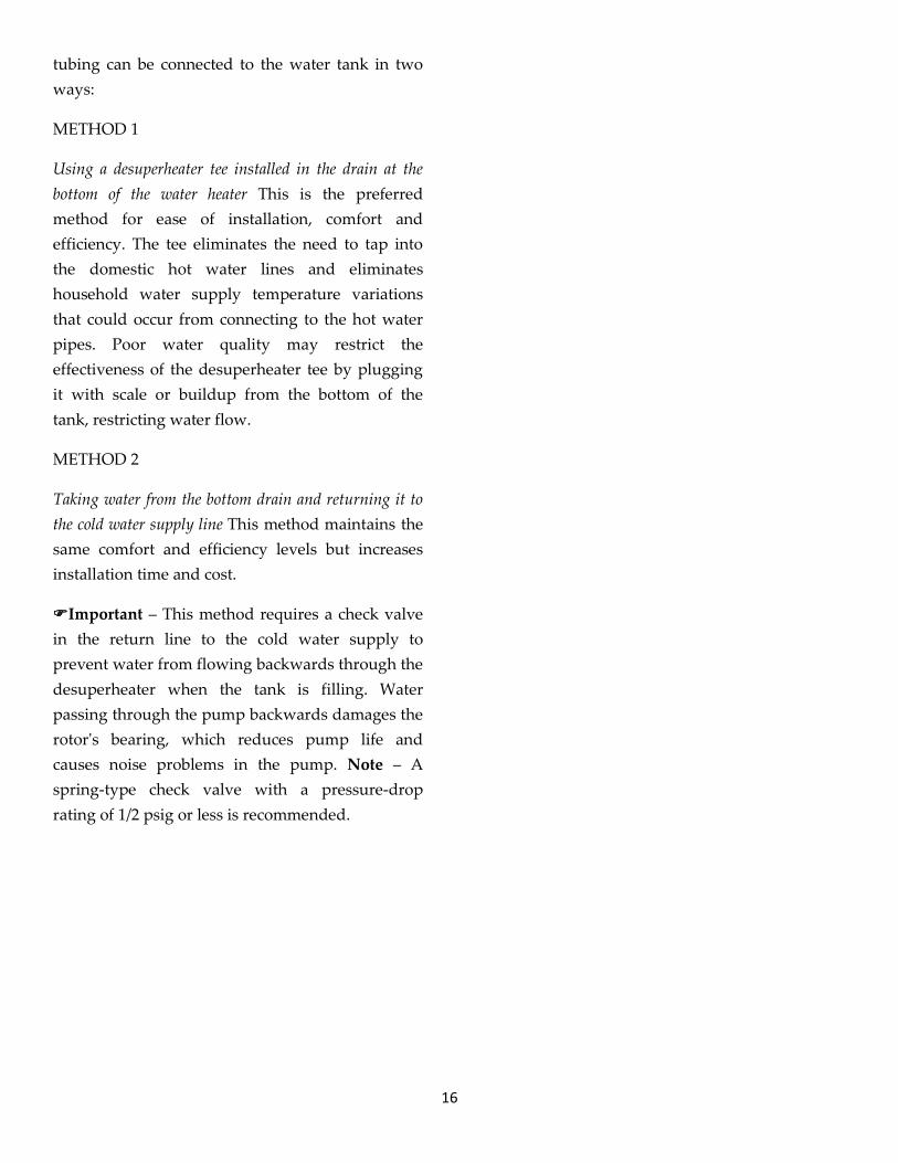
tubing can be connected to the water tank in two
ways:
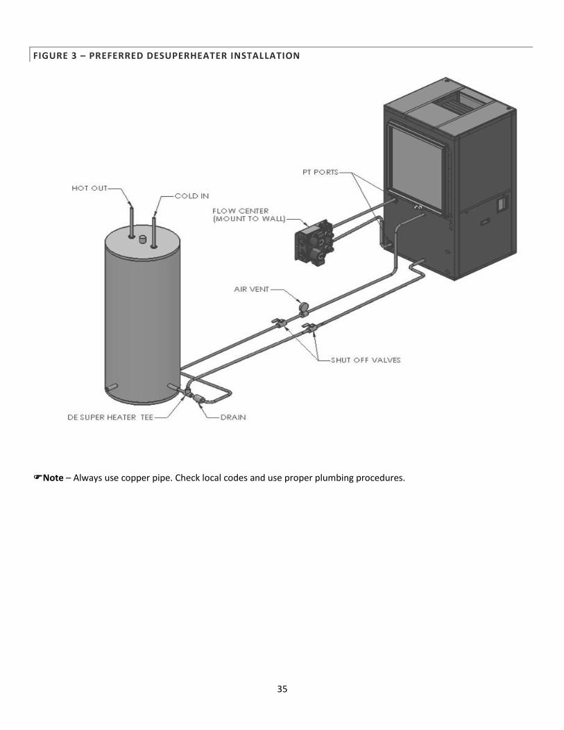
METHOD 1
Using a desuperheater tee installed in the drain at the
bottom of the water heater This is the preferred
method for ease of installation, comfort and
efficiency. The tee eliminates the need to tap into
the domestic hot water lines and eliminates
household water supply temperature variations
that could occur from connecting to the hot water
pipes. Poor water quality may restrict the
effectiveness of the desuperheater tee by plugging
it with scale or buildup from the bottom of the
tank, restricting water flow.
METHOD 2
Taking water from the bottom drain and returning it to
the cold water supply line This method maintains the
same comfort and efficiency levels but increases
installation time and cost.
Important – This method requires a check valve
in the return line to the cold water supply to
prevent water from flowing backwards through the
desuperheater when the tank is filling. Water
passing through the pump backwards damages the
rotor's bearing, which reduces pump life and
causes noise problems in the pump. Note – A
spring-type check valve with a pressure-drop
rating of 1/2 psig or less is recommended.

17
IX. ENGINEERING SPECIFICATIONS
PERFORMANCE RATINGS
RGS-V024 / RGT-V024 PERFORMANCE RATINGS
Heating Performance Data (Tested in accordance with ASHRAE/AHRI/ ISO Standard 13256-1)
Models Application Source
EWT (°F)
Entering GPM
(source)
Total Heat
Output (MBH) CFM COP
RGS-V024 Ground Water 50°F
6
25,000 1,000 4.5
Ground Loop 32°F * 19,000 1,000 3.7
RGT-V024
Full Load Ground Water 50°F 24,000 1,200 4.7
Ground Loop 32°F * 18,500 1,200 3.6
Part Load Ground Water 50°F 17,500 900 4.8
Ground Loop 41°F 15,500 900 4.2 * Antifreeze required
Cooling Performance Data (Tested in accordance with ASHRAE/AHRI/ ISO Standard 13256-1)
Models Application Source
EWT (°F)
Entering GPM
(source)
Total Cooling
Output (MBH) CFM EER
RGS-V024 Ground Water 59°F
6
30,400 1,000 22.0
Ground Loop 77°F 26,000 1,000 17.6
RGT-V024
Full Load Ground Water 59°F 26,500 1,200 19.9
Ground Loop 77°F 24,000 1,200 16.7
Part Load Ground Water 59°F 20,500 900 25.5
Ground Loop 68°F 19,500 900 22.1

18
RGS-V036 / RGT-V036 PERFORMANCE RATINGS
Heating Performance Data (Tested in accordance with ASHRAE/AHRI/ ISO Standard 13256-1)
Models Application Source
EWT (°F)
Entering GPM
(source)
Total Heat
Output (MBH) CFM COP
RGS-V036 Ground Water 50°F
9
34,500 1,000 4.3
Ground Loop 32°F * 27,500 1,000 3.6
RGT-V036
Full Load Ground Water 50°F 34,000 1,150 4.8
Ground Loop 32°F * 26,500 1,150 4.0
Part Load Ground Water 50°F 24,000 850 4.8
Ground Loop 41°F 21,000 850 4.3
* Antifreeze required
Cooling Performance Data (Tested in accordance with ASHRAE/AHRI/ ISO Standard 13256-1)
Models Application Source
EWT (°F)
Entering GPM
(source)
Total Cooling
Output (MBH) CFM EER
RGS-V036 Ground Water 59°F
9
41,000 1,000 22.0
Ground Loop 77°F 36,800 1,000 17.1
RGT-V036
Full Load Ground Water 59°F 41,500 1,150 24.4
Ground Loop 77°F 36,000 1,150 17.7
Part Load Ground Water 59°F 29,000 850 28.5
Ground Loop 68°F 27,500 850 24.2
19
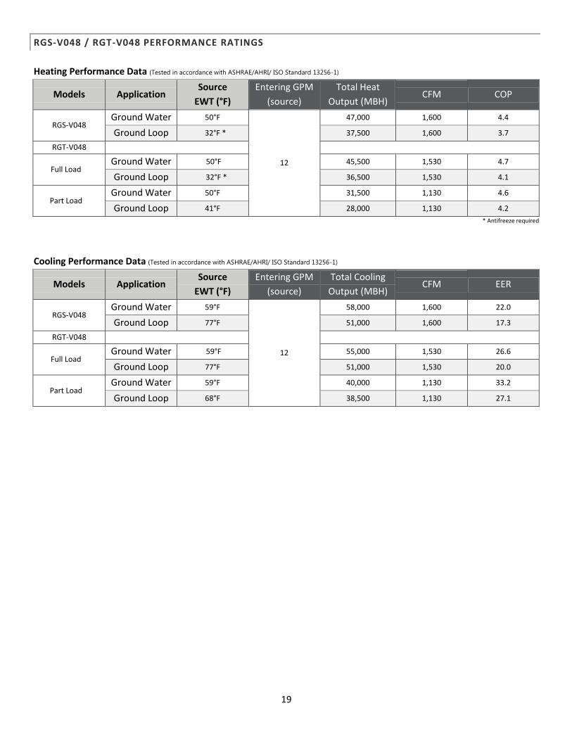
RGS-V048 / RGT-V048 PERFORMANCE RATINGS
Heating Performance Data (Tested in accordance with ASHRAE/AHRI/ ISO Standard 13256-1)
Models Application Source
EWT (°F)
Entering GPM
(source)
Total Heat
Output (MBH) CFM COP
RGS-V048 Ground Water 50°F
12
47,000 1,600 4.4
Ground Loop 32°F * 37,500 1,600 3.7
RGT-V048
Full Load Ground Water 50°F 45,500 1,530 4.7
Ground Loop 32°F * 36,500 1,530 4.1
Part Load Ground Water 50°F 31,500 1,130 4.6
Ground Loop 41°F 28,000 1,130 4.2
* Antifreeze required
Cooling Performance Data (Tested in accordance with ASHRAE/AHRI/ ISO Standard 13256-1)
Models Application Source
EWT (°F)
Entering GPM
(source)
Total Cooling
Output (MBH) CFM EER
RGS-V048 Ground Water 59°F
12
58,000 1,600 22.0
Ground Loop 77°F 51,000 1,600 17.3
RGT-V048
Full Load Ground Water 59°F 55,000 1,530 26.6
Ground Loop 77°F 51,000 1,530 20.0
Part Load Ground Water 59°F 40,000 1,130 33.2
Ground Loop 68°F 38,500 1,130 27.1

20
RGS-V060 / RGT-V060 PERFORMANCE RATINGS
Heating Performance Data (Tested in accordance with ASHRAE/AHRI/ ISO Standard 13256-1)
Models Application Source
EWT (°F)
Entering GPM
(source)
Total Heat
Output (MBH) CFM COP
RGS-V060 Ground Water 50°F
15
59,800 1,800 4.1
Ground Loop 32°F * 48,400 1,800 3.6
RGT-V060
Full Load Ground Water 50°F 54,500 1,820 4.3
Ground Loop 32°F * 41,600 1,820 3.6
Part Load Ground Water 50°F 37,000 1,400 4.1
Ground Loop 41°F 31,700 1,400 3.6
* Antifreeze required
Cooling Performance Data (Tested in accordance with ASHRAE/AHRI/ ISO Standard 13256-1)
Models Application Source
EWT (°F)
Entering GPM
(source)
Total Cooling
Output (MBH) CFM EER
RGS-V060 Ground Water 59°F
15
65,600 1,800 21.1
Ground Loop 77°F 60,600 1,800 17.1
RGT-V060
Full Load Ground Water 59°F 63,900 1,820 21.6
Ground Loop 77°F 58,000 1,820 17.8
Part Load Ground Water 59°F 49,200 1,400 25.2
Ground Loop 68°F 47,000 1,400 23.8

21
RGS-V072 / RGT-V072 PERFORMANCE RATINGS
Heating Performance Data (Tested in accordance with ASHRAE/AHRI/ ISO Standard 13256-1)
Models Application Source
EWT (°F)
Entering GPM
(source)
Total Heat
Output (MBH) CFM COP
RGS-V072 Ground Water 50°F
18
81,000 2,100 4.1
Ground Loop 32°F * 66,000 2,100 3.6
RGT-V072
Full Load Ground Water 50°F 67,500 2,110 4.2
Ground Loop 32°F * 53,500 2,110 3.6
Part Load Ground Water 50°F 49,000 1,400 4.3
Ground Loop 41°F 43,500 1,400 3.9
* Antifreeze required
Cooling Performance Data (Tested in accordance with ASHRAE/AHRI/ ISO Standard 13256-1)
Models Application Source
EWT (°F)
Entering GPM
(source)
Total Cooling
Output (MBH) CFM EER
RGS-V072 Ground Water 59°F
18
82,000 2,100 21.1
Ground Loop 77°F 79,000 2,100 17.1
RGT-V072
Full Load Ground Water 59°F 78,000 1,820 23.4
Ground Loop 77°F 71,000 1.820 18.0
Part Load Ground Water 59°F 59,000 1,400 30.0
Ground Loop 68°F 56,500 1,400 24.0

22
PERFORMANCE DATA
RGS-V024 HEATING & COOLING PERFORMANCE DATA (WITH ECM BLOWER)
* Operation at 40° EWT for long periods of time is not recommended, this is an extreme operating condition.
Data subject to change.
Pressure: Suction +/- 5 psig & Discharge P +/- 10 psig.
Pressure Drops with pure water.
23
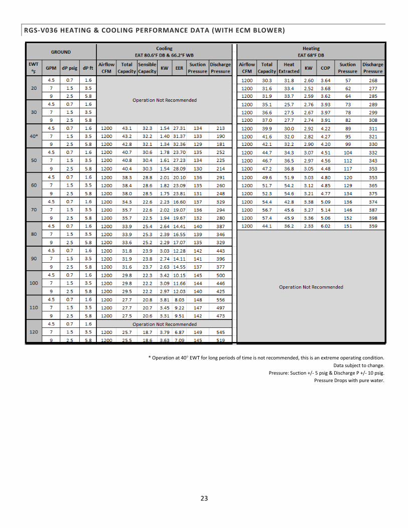
RGS-V036 HEATING & COOLING PERFORMANCE DATA (WITH ECM BLOWER)
* Operation at 40° EWT for long periods of time is not recommended, this is an extreme operating condition.
Data subject to change.
Pressure: Suction +/- 5 psig & Discharge P +/- 10 psig.
Pressure Drops with pure water.
24
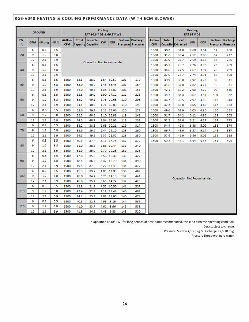
RGS-V048 HEATING & COOLING PERFORMANCE DATA (WITH ECM BLOWER)
* Operation at 40° EWT for long periods of time is not recommended, this is an extreme operating condition.
Data subject to change.
Pressure: Suction +/- 5 psig & Discharge P +/- 10 psig.
Pressure Drops with pure water.
25
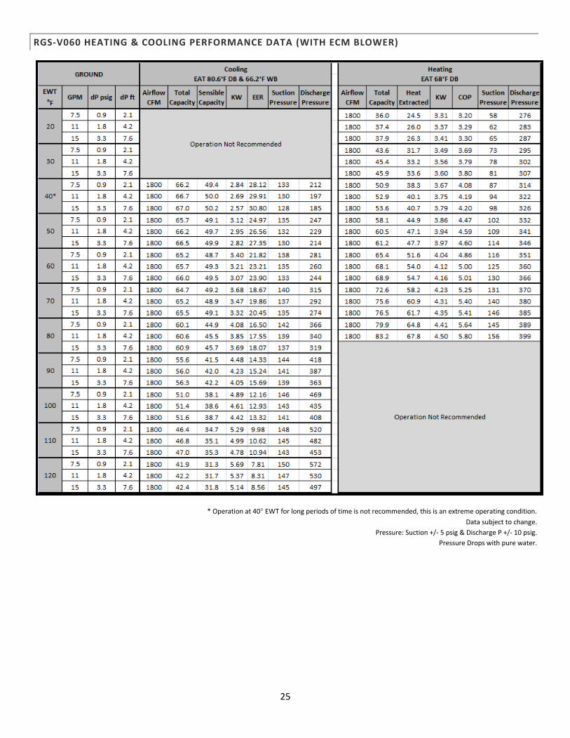
RGS-V060 HEATING & COOLING PERFORMANCE DATA (WITH ECM BLOWER)
* Operation at 40° EWT for long periods of time is not recommended, this is an extreme operating condition.
Data subject to change.
Pressure: Suction +/- 5 psig & Discharge P +/- 10 psig.
Pressure Drops with pure water.
26
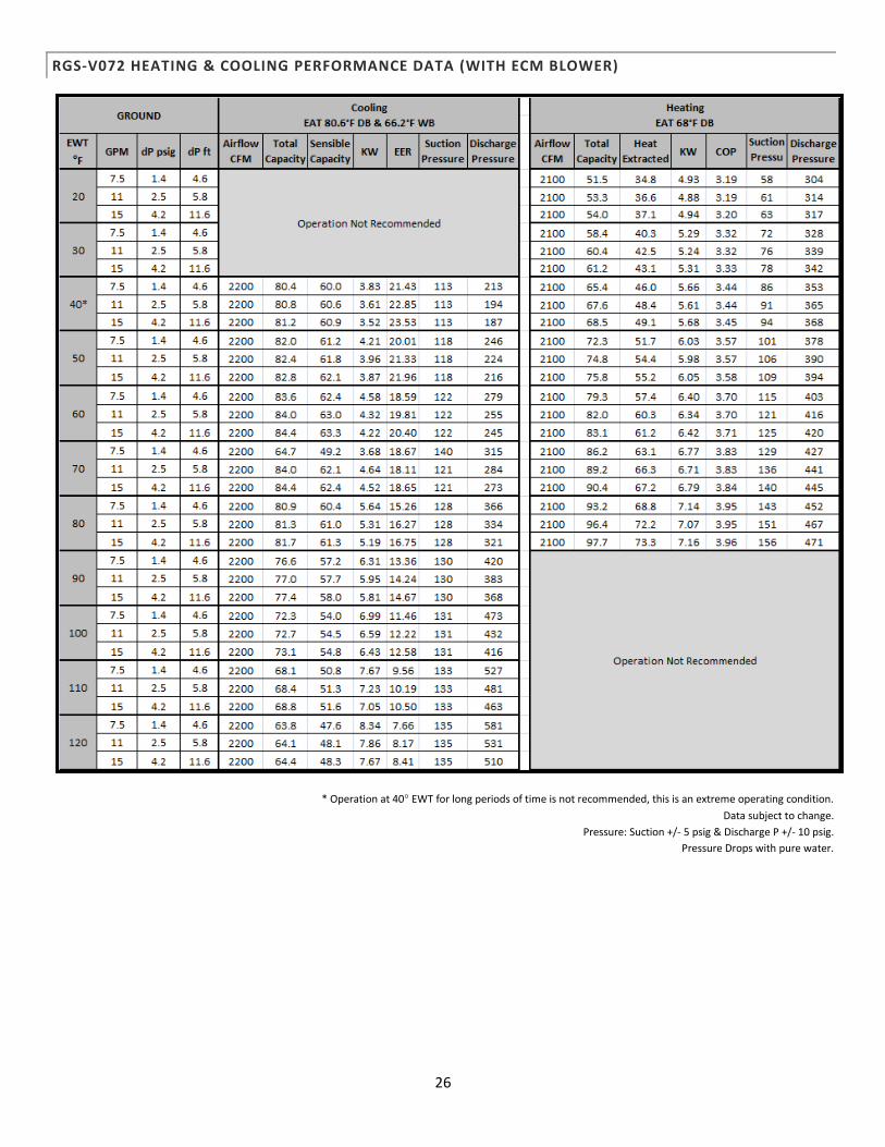
RGS-V072 HEATING & COOLING PERFORMANCE DATA (WITH ECM BLOWER)
* Operation at 40° EWT for long periods of time is not recommended, this is an extreme operating condition.
Data subject to change.
Pressure: Suction +/- 5 psig & Discharge P +/- 10 psig.
Pressure Drops with pure water.
27
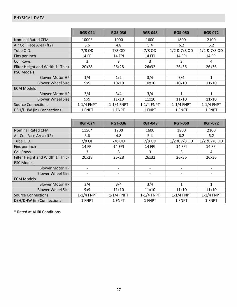
PHYSICAL DATA
RGS-024 RGS-036 RGS-048 RGS-060 RGS-072
Nominal Rated CFM 1000* 1000 1600 1800 2100
Air Coil Face Area (ft2) 3.6 4.8 5.4 6.2 6.2
Tube O.D. 7/8 OD 7/8 OD 7/8 OD 1/2 & 7/8 OD 1/2 & 7/8 OD
Fins per Inch 14 FPI 14 FPI 14 FPI 14 FPI 14 FPI
Coil Rows 3 3 3 3 4
Filter Height and Width 1" Thick 20x28 26x28 26x32 26x36 26x36
PSC Models
Blower Motor HP 1/4 1/2 3/4 3/4 1
Blower Wheel Size 9x9 10x10 10x10 10x10 11x10
ECM Models
Blower Motor HP 3/4 3/4 3/4 1 1
Blower Wheel Size 9x9 11x10 11x10 11x10 11x10
Source Connections 1-1/4 FNPT 1-1/4 FNPT 1-1/4 FNPT 1-1/4 FNPT 1-1/4 FNPT
DSH/DHW (in) Connections 1 FNPT 1 FNPT 1 FNPT 1 FNPT 1 FNPT
RGT-024 RGT-036 RGT-048 RGT-060 RGT-072
Nominal Rated CFM 1150* 1200 1600 1800 2100
Air Coil Face Area (ft2) 3.6 4.8 5.4 6.2 6.2
Tube O.D. 7/8 OD 7/8 OD 7/8 OD 1/2 & 7/8 OD 1/2 & 7/8 OD
Fins per Inch 14 FPI 14 FPI 14 FPI 14 FPI 14 FPI
Coil Rows 3 3 3 3 4
Filter Height and Width 1" Thick 20x28 26x28 26x32 26x36 26x36
PSC Models
Blower Motor HP - - - - -
Blower Wheel Size - - - - -
ECM Models
Blower Motor HP 3/4 3/4 3/4 1 1
Blower Wheel Size 9x9 11x10 11x10 11x10 11x10
Source Connections 1-1/4 FNPT 1-1/4 FNPT 1-1/4 FNPT 1-1/4 FNPT 1-1/4 FNPT
DSH/DHW (in) Connections 1 FNPT 1 FNPT 1 FNPT 1 FNPT 1 FNPT
* Rated at AHRI Conditions

28
UNIT DIMENSIONS
Dimension Measurement in Inches
2 Ton 3-4 Ton 5-6 Ton
A 31.75 31.75 31.75
B 59.13 63.13 63.13
C 27.88 27.88 27.88
D 3.63 5.00 2.87
E 5.43 2.88 2.88
F 17.88 17.88 17.88
G 28.75 28.75 28.75
H 3.13 3.13 3.13
J 2.38 2.38 2.38
K 2.83 2.83 2.83
L 10.75 10.75 10.75
M 21.63 21.63 21.63
N 22.38 18.43 22.375
P 26.50 26.50 26.5
Q 3.38 3.38 3.38
R 12.43 12.43 12.43
S 9.30 9.30 9.30
T 13.10 13.10 13.10
U 11.68 11.68 11.68
V 27.00 31.00 35.00
W 25.00 25.00 25.00
X 14.00 14.00 14.00
29
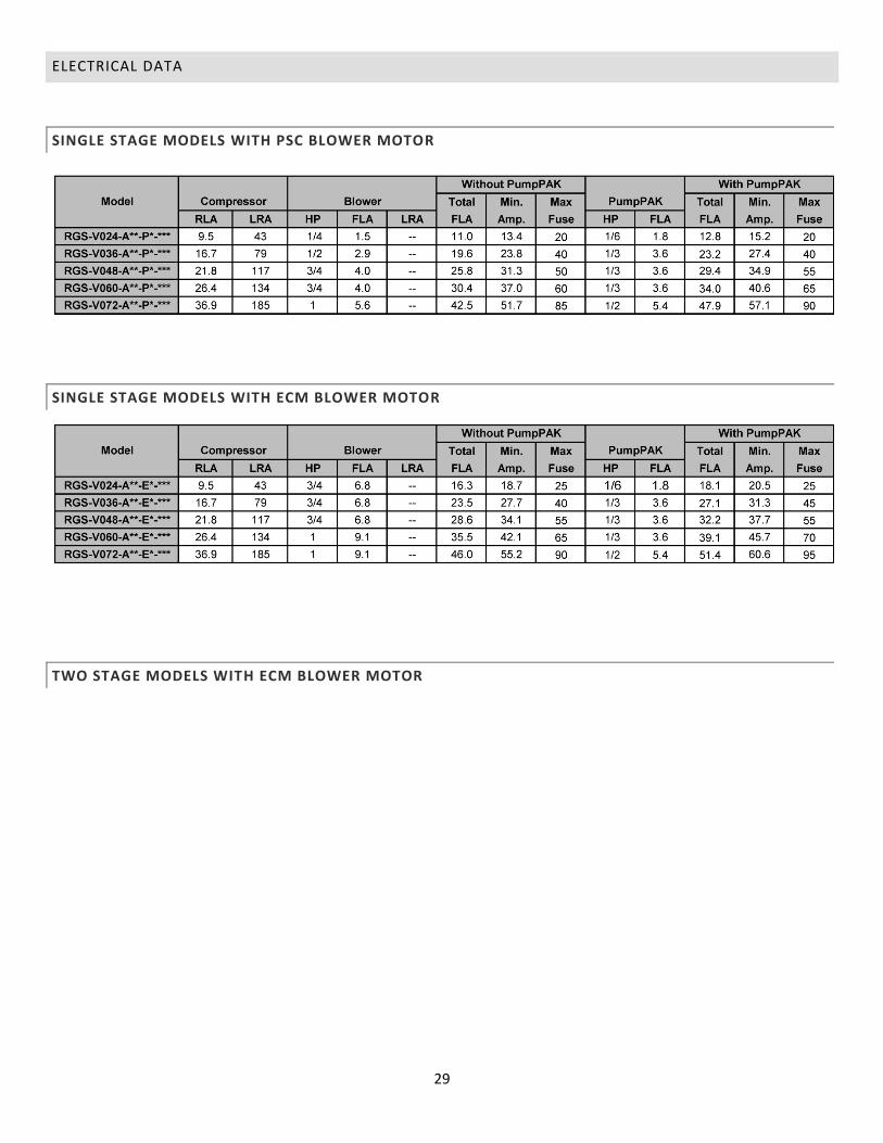
ELECTRICAL DATA
SINGLE STAGE MODELS WITH PSC BLOWER MOTOR
SINGLE STAGE MODELS WITH ECM BLOWER MOTOR
TWO STAGE MODELS WITH ECM BLOWER MOTOR
30
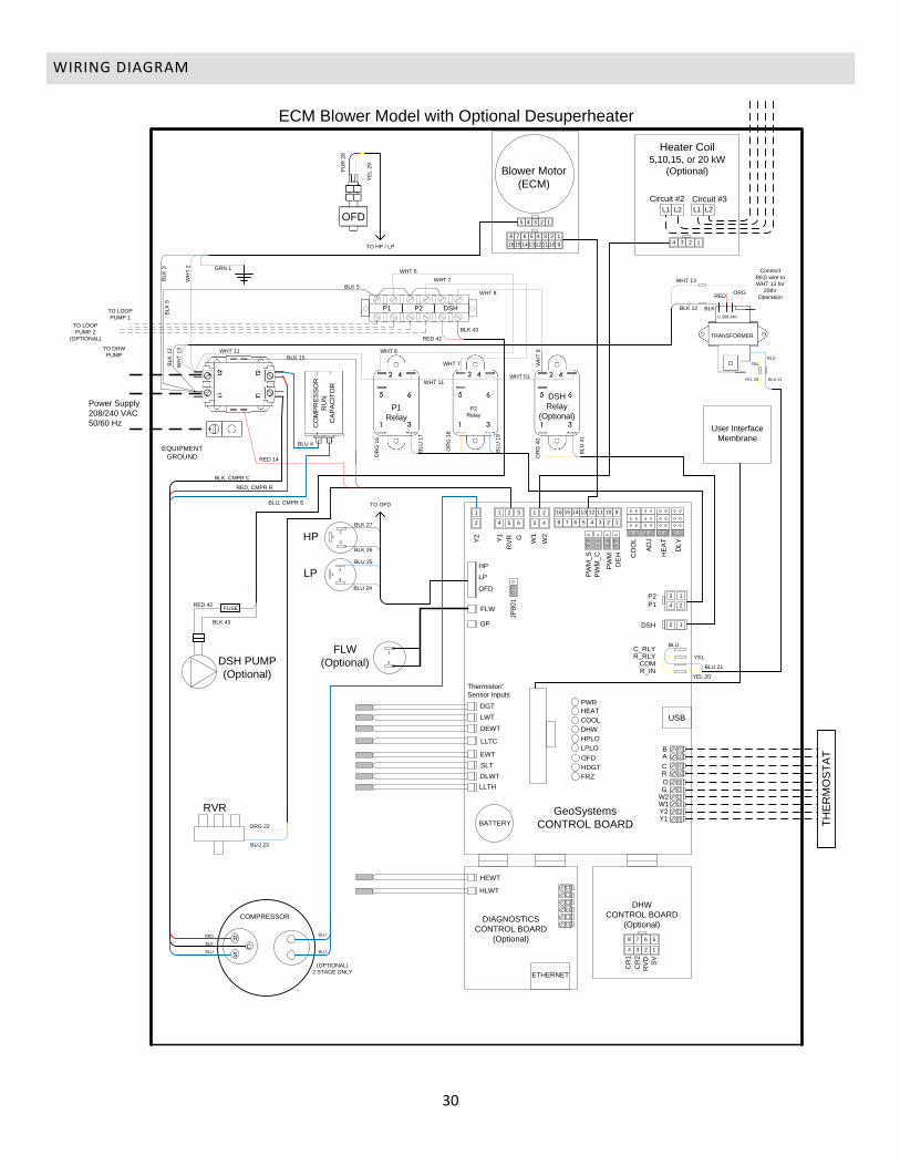
WIRING DIAGRAM
ECM Blower Model with Optional Desuperheater
DGT
LWT
EWT
DEWT
DLWT
LLTH
SLT
HLWT
HEWT
RVR
S
C
R
GeoSystems
CONTROL BOARD
9
1
10
2
11
3
12
4
13
5
14
6
15
7
16
8
TO LOOP
PUMP 1
TO LOOP
PUMP 2
(OPTIONAL)
TO DHW
PUMP
DSH PUMP
(Optional)
TH
ER
MO
ST
AT
COMPRESSOR
R_INCOM
R_RLYC_RLY
HP
LP
OFD
OFD
FLW
GPC
R1
CR
2
RV
D
SV
W1
W2
DHW
CONTROL BOARD
(Optional)DIAGNOSTICS
CONTROL BOARD
(Optional)
Power Supply
208/240 VAC
50/60 Hz
DSH
P1
P2
Y2
RC
AB
W1W2GO
Y1Y2
PW
M_S
PW
M_C
PW
M
DE
H CO
OL
AD
J
HE
AT
DL
Y
BATTERY
ETHERNET
USB
1234
5678
PWR
HEAT
COOL
DHW
HPLO
LPLO
2 1
3 1
4 2
3
1
4
2
5
2
6
3
4
1
Y1
RV
R G2
1
LLTC
OFD
HDGT
FRZ
Thermistor/
Sensor Inputs
JP
80
1
1234
L1 L2 L1 L2
Heater Coil5,10,15, or 20 kW
(Optional)
Circuit #2 Circuit #3
Blower Motor
(ECM)
1
9
2
10
3
11
4
12
5
13
6
14
7
15
8
16
12345
CO
MP
RE
SS
OR
RU
N
CA
PA
CIT
OR
P1
Relay
P2
Relay
DSH
Relay
(Optional)
User Interface
Membrane
EQUIPMENT
GROUND
HP2
1
3
LP2
1
3
FLW
(Optional)1
2
TRANSFORMER
C 208 240
BLU 21YEL 20
TO OFD
TO HP / LP
P1 P2 DSH
FUSE
(OPTIONAL)
2 STAGE ONLY
BLU
BLUBLU
BLK
RED
PU
R 2
8
GRN 1
BL
K 3
WH
T 2
BLK 5
BL
K 5
BL
K 1
2
WH
T 1
3 WHT 11
BLU 4
BLK 15
RED 14
BLK, CMPR C
RED, CMPR R
BLU, CMPR S
WHT 11
WHT 13
BLK 12
WHT 6
WHT 7
WHT 6
WHT 7 WH
T 8
WHT 8
WHT 51
YE
L 2
9
Connect
RED wire to
WHT 13 for
208V
OperationORG
RED
BLK
BLU
YEL
BLK 43
RED 42
BL
U 1
7
BL
U 1
9
BL
U 4
1
OR
G 1
6
OR
G 1
8
OR
G 4
0
BLU 21
YEL
YEL 20
BLU
BLK 43
RED 42
ORG 22
BLU 23
BLU 25
BLU 24
BLK 27
BLK 26
31
DSH
Relay
(Optional)
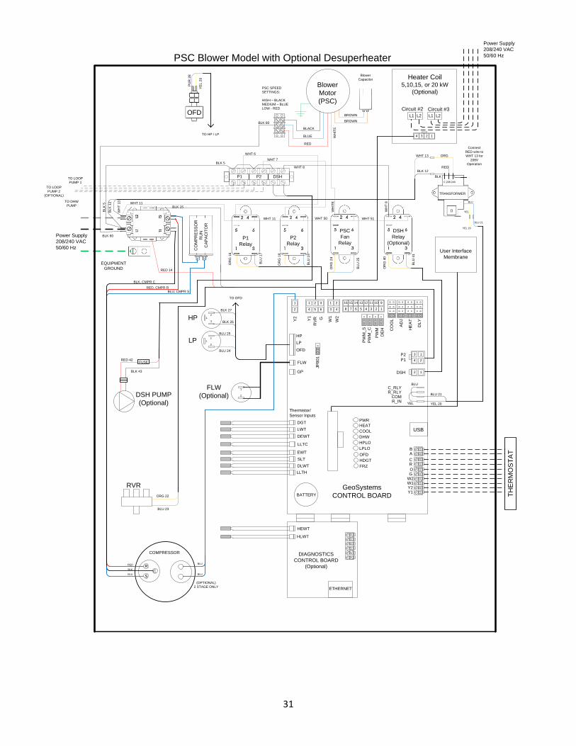
PSC Blower Model with Optional Desuperheater
DGT
LWT
EWT
DEWT
DLWT
LLTH
SLT
HLWT
HEWT
RVR
S
C
R
GeoSystems
CONTROL BOARD
9
1
10
2
11
3
12
4
13
5
14
6
15
7
16
8
TO LOOP
PUMP 1
TO LOOP
PUMP 2
(OPTIONAL)
TO DHW
PUMP
DSH PUMP
(Optional)
TH
ER
MO
ST
AT
COMPRESSOR
R_INCOM
R_RLYC_RLY
HP
LP
OFD
FLW
GP
W1
W2
DIAGNOSTICS
CONTROL BOARD
(Optional)
Power Supply
208/240 VAC
50/60 Hz
Power Supply
208/240 VAC
50/60 Hz
DSH
P1
P2
Y2
RC
AB
W1W2GO
Y1Y2
PW
M_
S
PW
M_
C
PW
M
DE
H CO
OL
AD
J
HE
AT
DL
Y
BATTERY
ETHERNET
USB
PWR
HEAT
COOL
DHW
HPLO
LPLO
2 1
3 1
4 2
3
1
4
2
5
2
6
3
4
1
Y1
RV
R G
2
1
LLTC
OFD
HDGT
FRZ
Thermistor/
Sensor Inputs
JP
80
1
1234
L1 L2 L1 L2
Heater Coil5,10,15, or 20 kW
(Optional)
Circuit #2 Circuit #3
CO
MP
RE
SS
OR
RU
N
CA
PA
CIT
OR
P1
Relay
P2
Relay
PSC
Fan
Relay
User Interface
Membrane
EQUIPMENT
GROUND
HP2
1
3
LP2
1
3
FLW
(Optional)1
2
TO OFD
P1 P2 DSH
FUSE
(OPTIONAL)
2 STAGE ONLY
BLU
BLUBLU
BLK
RED
Blower
Motor
(PSC)
Blower
Capacitor
TRANSFORMER
C 208 240
BLU
YEL
WHT 13
BLK 12
ORG
RED
BLK
Connect
RED wire to
WHT 13 for
208V
Operation
YEL 20
BLU 21
OFD
PU
R 2
8
YE
L 2
9
TO HP / LP
WHT 6
BROWN
BROWN
WHT 7
PSC SPEED
SETTINGS:
HIGH – BLACK
MEDIUM – BLUE
LOW - RED
BLK 60
BLACK
BLUE
RED
BLK 60
BL
K 5
BL
K 1
2
BLK 5
WH
T 1
3
WHT 11
WHT 11
BLK 15
RED 14
BLK 27
BLK 26
BLU 25
BLU 24
OR
G 1
6
BL
U 1
7
OR
G 1
8
BL
U 1
9
ORG 22
BLU 23
RED 42
BLK 43
OR
G 2
4
OR
G 4
0
BL
U 2
5
BL
U 4
1
WHT 8
WH
T 8
WH
ITE
WH
ITE
WHT 50 WHT 51
BLU
YEL 20YEL
BLU 21
BLU, CMPR SRED, CMPR R
BLK, CMPR C
32
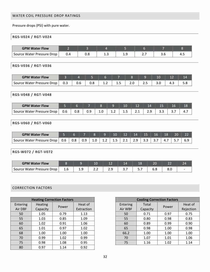
WATER COIL PRESSURE DROP RATINGS
Pressure drops (PSI) with pure water.
RGS-V024 / RGT-V024
GPM Water Flow 2 3 4 5 6 7 8
Source Water Pressure Drop 0.4 0.8 1.3 1.9 2.7 3.6 4.5
RGS-V036 / RGT-V036
GPM Water Flow 3 4 5 6 7 8 9 10 12 14
Source Water Pressure Drop 0.3 0.6 0.8 1.2 1.5 2.0 2.5 3.0 4.3 5.8
RGS-V048 / RGT-V048
GPM Water Flow 5 6 7 8 9 10 12 14 15 16 18
Source Water Pressure Drop 0.6 0.8 0.9 1.0 1.2 1.5 2.1 2.9 3.3 3.7 4.7
RGS-V060 / RGT-V060
GPM Water Flow 5 6 7 8 9 10 12 14 15 16 18 20 22
Source Water Pressure Drop 0.6 0.8 0.9 1.0 1.2 1.5 2.1 2.9 3.3 3.7 4.7 5.7 6.9
RGS-W072 / RGT-V072
GPM Water Flow 8 9 10 12 14 18 20 22 24
Source Water Pressure Drop 1.6 1.9 2.2 2.9 3.7 5.7 6.8 8.0 -
CORRECTION FACTORS
Heating Correction Factors Cooling Correction Factors
Entering Air DBF
Heating Capacity
Power Heat of
Extraction
Entering Air WBF
Total Capacity
Power Heat of
Rejection
50 1.05 0.79 1.13 50 0.71 0.97 0.75
55 1.03 0.85 1.09 55 0.80 0.98 0.83
60 1.02 0.91 1.06 60 0.89 0.99 0.90
65 1.01 0.97 1.02 65 0.98 1.00 0.98
68 1.00 1.00 1.00 66.2 1.00 1.00 1.00
70 0.99 1.02 0.99 70 1.07 1.01 1.06
75 0.98 1.08 0.95 75 1.16 1.02 1.14
80 0.97 1.14 0.92

33
BLOWER PERFORMANCE
ECM BLOWER DATA
Model Speed Tap G Only Full Load Heating &
Cooling Auxiliary Heat
RG*-V024 C 350 800 1000
RG*-V036 B 480 1100 1200
RG*-V048 A 680 1550 1600
RG*-V060 B 800 1800 2000
RG*-V072 A 1000 2200 2300
When part load is available CFM will be 76% of the full load rating.
Using the +/- Jumpers will result in + or - 10% of the ratings.
Test at .6 Static
PSC BLOWER DATA
*Factory Default Setting
34
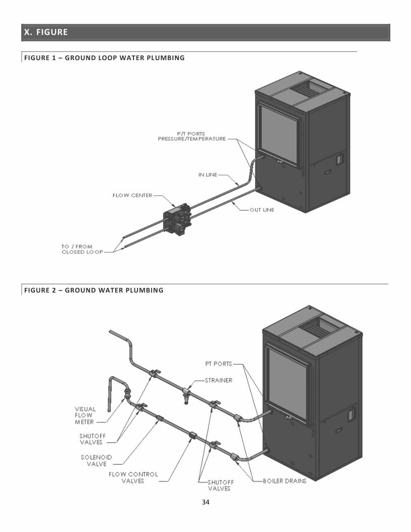
X. FIGURE
FIGURE 1 – GROUND LOOP WATER PLUMBING
FIGURE 2 – GROUND WATER PLUMBING
35
FIGURE 3 – PREFERRED DESUPERHEATER INSTALLATION
Note – Always use copper pipe. Check local codes and use proper plumbing procedures.

36
FIGURE 4 – ALTERNATIVE DESUPERHEATER INSTALLATION
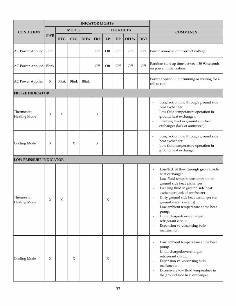
XI. TROUBLESHOOTING
If the heat pump goes into lockout on a high or low pressure switch or discharge refrigerant temperature, the
cause of the lockout can be narrowed down by knowing the operating mode and which switch the unit locked
out on. The following table will help track down the problem once this information is known.
Important – A lockout condition is a result of the heat pump shutting off to protect itself. Never bypass the
lockout circuit. Serious damage can be caused by the system operating without lockout protection.
37
CONDITION
INICATOR LIGHTS
COMMENTS PWR
MODES LOCKOUTS
HTG CLG DHW FRZ LP HP OFLW DGT
AC Power Applied Off
Off Off Off Off Off Power removed or incorrect voltage.
AC Power Applied Blink
Off Off Off Off Off Random start up time between 30-90 seconds
on power initialization.
AC Power Applied X Blink Blink Blink
Power applied - unit running or waiting for a
call to run.
FREEZE INDICATOR
Thermostat
Heating Mode X X X
- Loss/lack of flow through ground side
heat exchanger.
- Low fluid temperature operation in
ground heat exchanger.
- Freezing fluid in ground side heat
exchanger (lack of antifreeze)
Cooling Mode X X X
- Loss/lack of flow through ground side
heat exchanger.
- Low fluid temperature operation in
ground heat exchanger.
LOW PRESSURE INDICATOR
Thermostat
Heating Mode X X
X
- Loss/lack of flow through ground side
heat exchanger.
- Low fluid temperature operation in
ground side heat exchanger.
- Freezing fluid in ground side heat
exchanger (lack of antifreeze)
- Dirty ground side heat exchanger (on
ground water systems)
- Low ambient temperature at the heat
pump.
- Undercharged/ overcharged
refrigerant circuit.
- Expansion valve/sensing bulb
malfunction.
Cooling Mode X X
X
- Low ambient temperature at the heat
pump.
- Undercharged/overcharged
refrigerant circuit.
- Expansion valve/sensing bulb
malfunction.
- Excessively low fluid temperature in
the ground side heat exchanger.
38
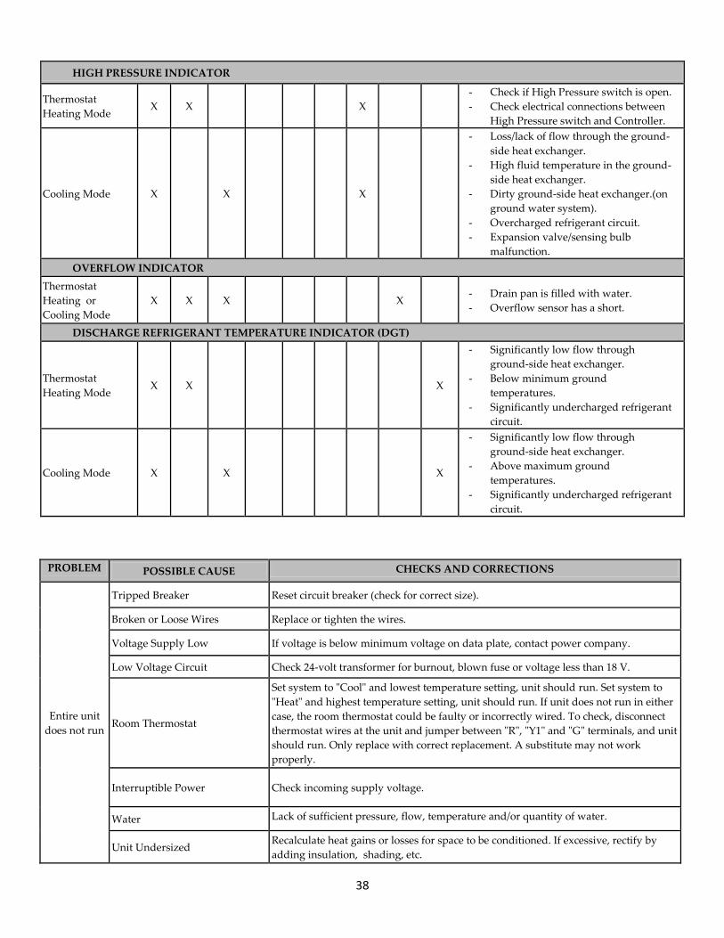
HIGH PRESSURE INDICATOR
Thermostat
Heating Mode X X
X
- Check if High Pressure switch is open.
- Check electrical connections between
High Pressure switch and Controller.
Cooling Mode X X
X
- Loss/lack of flow through the ground-
side heat exchanger.
- High fluid temperature in the ground-
side heat exchanger.
- Dirty ground-side heat exchanger.(on
ground water system).
- Overcharged refrigerant circuit.
- Expansion valve/sensing bulb
malfunction.
OVERFLOW INDICATOR
Thermostat
Heating or
Cooling Mode
X X X
X
- Drain pan is filled with water.
- Overflow sensor has a short.
DISCHARGE REFRIGERANT TEMPERATURE INDICATOR (DGT)
Thermostat
Heating Mode X X
X
- Significantly low flow through
ground-side heat exchanger.
- Below minimum ground
temperatures.
- Significantly undercharged refrigerant
circuit.
Cooling Mode X X
X
- Significantly low flow through
ground-side heat exchanger.
- Above maximum ground
temperatures.
- Significantly undercharged refrigerant
circuit.
PROBLEM POSSIBLE CAUSE CHECKS AND CORRECTIONS
Entire unit
does not run
Tripped Breaker Reset circuit breaker (check for correct size).
Broken or Loose Wires Replace or tighten the wires.
Voltage Supply Low If voltage is below minimum voltage on data plate, contact power company.
Low Voltage Circuit Check 24-volt transformer for burnout, blown fuse or voltage less than 18 V.
Room Thermostat
Set system to "Cool" and lowest temperature setting, unit should run. Set system to
"Heat" and highest temperature setting, unit should run. If unit does not run in either
case, the room thermostat could be faulty or incorrectly wired. To check, disconnect
thermostat wires at the unit and jumper between "R", "Y1" and "G" terminals, and unit
should run. Only replace with correct replacement. A substitute may not work
properly.
Interruptible Power Check incoming supply voltage.
Water Lack of sufficient pressure, flow, temperature and/or quantity of water.
Unit Undersized Recalculate heat gains or losses for space to be conditioned. If excessive, rectify by
adding insulation, shading, etc.
39
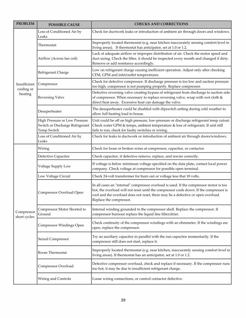
PROBLEM POSSIBLE CAUSE CHECKS AND CORRECTIONS
Insufficient
cooling or
heating
Loss of Conditioned Air by
Leaks
Check for ductwork leaks or introduction of ambient air through doors and windows.
Thermostat Improperly located thermostat (e.g. near kitchen inaccurately sensing comfort level in
living areas). If thermostat has anticipator, set at 1.0 or 1.2.
Airflow (Across fan coil)
Lack of adequate airflow or improper distribution of air. Check the motor speed and
duct sizing. Check the filter, it should be inspected every month and changed if dirty.
Remove or add resistance accordingly.
Refrigerant Charge Low on refrigerant charge causing inefficient operation. Adjust only after checking
CFM, GPM and inlet/outlet temperatures.
Compressor Check for defective compressor. If discharge pressure is too low and suction pressure
too high, compressor is not pumping properly. Replace compressor.
Reversing Valve
Defective reversing valve creating bypass of refrigerant from discharge to suction side
of compressor. When necessary to replace reversing valve, wrap with wet cloth &
direct heat away. Excessive heat can damage the valve.
Desuperheater The desuperheater could be disabled with dipswitch setting during cold weather to
allow full heating load to house.
High Pressure or Low Pressure
Switch or Discharge Refrigerant
Temp Switch
Unit could be off on high pressure, low-pressure or discharge refrigerant temp cutout.
Check water GPM & temps, ambient temperature & loss of refrigerant. If unit still
fails to run, check for faulty switches or wiring.
Loss of Conditioned Air by
Leaks
Check for leaks in ductwork or introduction of ambient air through doors/windows.
Compressor
short cycles.
Wiring Check for loose or broken wires at compressor, capacitor, or contactor.
Defective Capacitor Check capacitor, if defective remove, replace, and rewire correctly.
Voltage Supply Low If voltage is below minimum voltage specified on the data plate, contact local power
company. Check voltage at compressor for possible open terminal.
Low Voltage Circuit Check 24-volt transformer for burn out or voltage less that 18 volts.
Compressor Overload Open
In all cases an "internal" compressor overload is used. If the compressor motor is too
hot, the overload will not reset until the compressor cools down. If the compressor is
cool and the overload does not reset, there may be a defective or open overload.
Replace the compressor.
Compressor Motor Shorted to
Ground
Internal winding grounded to the compressor shell. Replace the compressor. If
compressor burnout replace the liquid line filter/drier.
Compressor Windings Open Check continuity of the compressor windings with an ohmmeter. If the windings are
open, replace the compressor.
Seized Compressor Try an auxiliary capacitor in parallel with the run capacitor momentarily. If the
compressor still does not start, replace it.
Room Thermostat Improperly located thermostat (e.g. near kitchen, inaccurately sensing comfort level in
living areas). If thermostat has an anticipator, set at 1.0 or 1.2.
Compressor Overload Defective compressor overload, check and replace if necessary. If the compressor runs
too hot, it may be due to insufficient refrigerant charge.
Wiring and Controls Loose wiring connections, or control contactor defective.
40
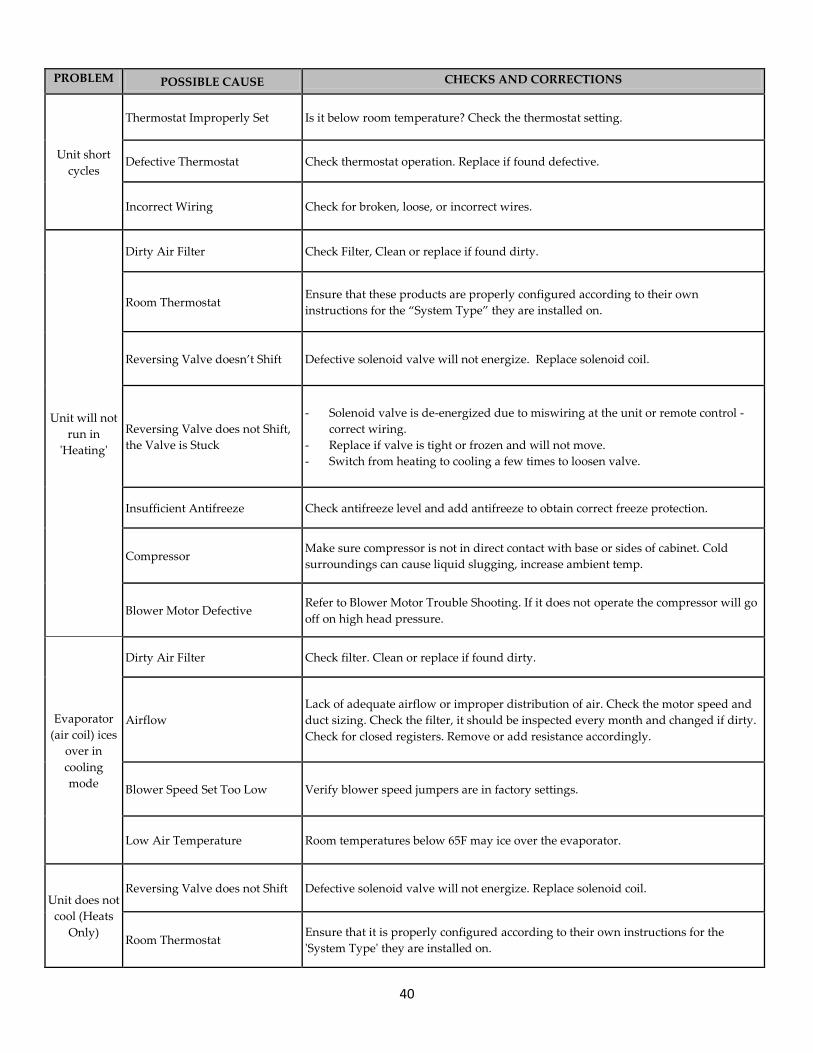
PROBLEM POSSIBLE CAUSE CHECKS AND CORRECTIONS
Unit short
cycles
Thermostat Improperly Set Is it below room temperature? Check the thermostat setting.
Defective Thermostat Check thermostat operation. Replace if found defective.
Incorrect Wiring Check for broken, loose, or incorrect wires.
Unit will not
run in
'Heating'
Dirty Air Filter Check Filter, Clean or replace if found dirty.
Room Thermostat Ensure that these products are properly configured according to their own
instructions for the “System Type” they are installed on.
Reversing Valve doesn’t Shift Defective solenoid valve will not energize. Replace solenoid coil.
Reversing Valve does not Shift,
the Valve is Stuck
- Solenoid valve is de-energized due to miswiring at the unit or remote control -
correct wiring.
- Replace if valve is tight or frozen and will not move.
- Switch from heating to cooling a few times to loosen valve.
Insufficient Antifreeze Check antifreeze level and add antifreeze to obtain correct freeze protection.
Compressor Make sure compressor is not in direct contact with base or sides of cabinet. Cold
surroundings can cause liquid slugging, increase ambient temp.
Blower Motor Defective Refer to Blower Motor Trouble Shooting. If it does not operate the compressor will go
off on high head pressure.
Evaporator
(air coil) ices
over in
cooling
mode
Dirty Air Filter Check filter. Clean or replace if found dirty.
Airflow
Lack of adequate airflow or improper distribution of air. Check the motor speed and
duct sizing. Check the filter, it should be inspected every month and changed if dirty.
Check for closed registers. Remove or add resistance accordingly.
Blower Speed Set Too Low Verify blower speed jumpers are in factory settings.
Low Air Temperature Room temperatures below 65F may ice over the evaporator.
Unit does not
cool (Heats
Only)
Reversing Valve does not Shift Defective solenoid valve will not energize. Replace solenoid coil.
Room Thermostat Ensure that it is properly configured according to their own instructions for the
'System Type' they are installed on.
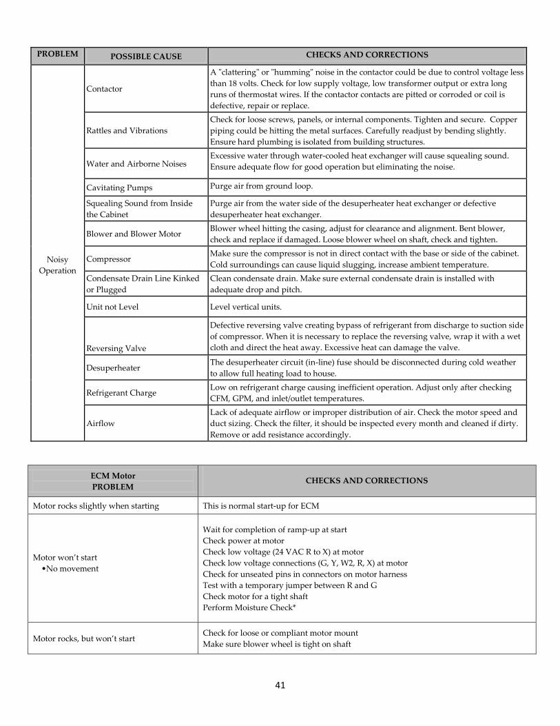
41
PROBLEM POSSIBLE CAUSE CHECKS AND CORRECTIONS
Contactor
A "clattering" or "humming" noise in the contactor could be due to control voltage less
than 18 volts. Check for low supply voltage, low transformer output or extra long
runs of thermostat wires. If the contactor contacts are pitted or corroded or coil is
defective, repair or replace.
Noisy
Operation
Rattles and Vibrations
Check for loose screws, panels, or internal components. Tighten and secure. Copper
piping could be hitting the metal surfaces. Carefully readjust by bending slightly.
Ensure hard plumbing is isolated from building structures.
Water and Airborne Noises Excessive water through water-cooled heat exchanger will cause squealing sound.
Ensure adequate flow for good operation but eliminating the noise.
Cavitating Pumps Purge air from ground loop.
Squealing Sound from Inside
the Cabinet
Purge air from the water side of the desuperheater heat exchanger or defective
desuperheater heat exchanger.
Blower and Blower Motor Blower wheel hitting the casing, adjust for clearance and alignment. Bent blower,
check and replace if damaged. Loose blower wheel on shaft, check and tighten.
Compressor Make sure the compressor is not in direct contact with the base or side of the cabinet.
Cold surroundings can cause liquid slugging, increase ambient temperature.
Condensate Drain Line Kinked
or Plugged
Clean condensate drain. Make sure external condensate drain is installed with
adequate drop and pitch.
Unit not Level Level vertical units.
Reversing Valve
Defective reversing valve creating bypass of refrigerant from discharge to suction side
of compressor. When it is necessary to replace the reversing valve, wrap it with a wet
cloth and direct the heat away. Excessive heat can damage the valve.
Desuperheater The desuperheater circuit (in-line) fuse should be disconnected during cold weather
to allow full heating load to house.
Refrigerant Charge Low on refrigerant charge causing inefficient operation. Adjust only after checking
CFM, GPM, and inlet/outlet temperatures.
Airflow
Lack of adequate airflow or improper distribution of air. Check the motor speed and
duct sizing. Check the filter, it should be inspected every month and cleaned if dirty.
Remove or add resistance accordingly.
ECM Motor
PROBLEM CHECKS AND CORRECTIONS
Motor rocks slightly when starting This is normal start-up for ECM
Motor won’t start
•No movement
Wait for completion of ramp-up at start
Check power at motor
Check low voltage (24 VAC R to X) at motor
Check low voltage connections (G, Y, W2, R, X) at motor
Check for unseated pins in connectors on motor harness
Test with a temporary jumper between R and G
Check motor for a tight shaft
Perform Moisture Check*
Motor rocks, but won’t start Check for loose or compliant motor mount
Make sure blower wheel is tight on shaft
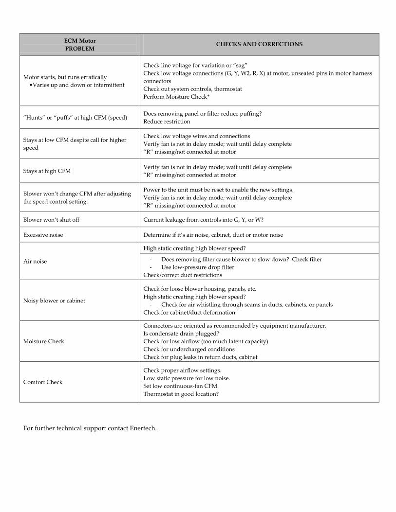
ECM Motor
PROBLEM CHECKS AND CORRECTIONS
Motor starts, but runs erratically
•Varies up and down or intermittent
Check line voltage for variation or “sag”
Check low voltage connections (G, Y, W2, R, X) at motor, unseated pins in motor harness
connectors
Check out system controls, thermostat
Perform Moisture Check*
”Hunts” or “puffs” at high CFM (speed) Does removing panel or filter reduce puffing?
Reduce restriction
Stays at low CFM despite call for higher
speed
Check low voltage wires and connections
Verify fan is not in delay mode; wait until delay complete
”R” missing/not connected at motor
Stays at high CFM Verify fan is not in delay mode; wait until delay complete
”R” missing/not connected at motor
Blower won’t change CFM after adjusting
the speed control setting.
Power to the unit must be reset to enable the new settings.
Verify fan is not in delay mode; wait until delay complete
”R” missing/not connected at motor
Blower won’t shut off Current leakage from controls into G, Y, or W?
Excessive noise Determine if it’s air noise, cabinet, duct or motor noise
Air noise
High static creating high blower speed?
- Does removing filter cause blower to slow down? Check filter
- Use low-pressure drop filter
Check/correct duct restrictions
Noisy blower or cabinet
Check for loose blower housing, panels, etc.
High static creating high blower speed?
- Check for air whistling through seams in ducts, cabinets, or panels
Check for cabinet/duct deformation
Moisture Check
Connectors are oriented as recommended by equipment manufacturer.
Is condensate drain plugged?
Check for low airflow (too much latent capacity)
Check for undercharged conditions
Check for plug leaks in return ducts, cabinet
Comfort Check
Check proper airflow settings.
Low static pressure for low noise.
Set low continuous-fan CFM.
Thermostat in good location?
For further technical support contact Enertech.

Greenville, IL & Mitchell, SD
www.gogogeo.com
040-00059 Rev. F | November 2012 | ©2012 Enertech Global, LLC. | All Rights Reserved