Embed Size (px)
Citation preview

2801 Carlisle AvenueRacine, WI 53404Phone: 800.358-5872 or
262.633-5070Fax: 262.633-5102
Website: www.ultradustcollectors.com
INSTALLATION, OPERATION &MAINTENANCE MANUAL
BB, BW, BD, CB, CW, CL, CD, NW, ND SERIES
Issue Date: March 2015

Ultra Industries, Inc. i
TABLE OF CONTENTS
Receiving Your Collector ............................................................................1
Operating Principles ....................................................................................2
Mounting The Differential Pressure Gauge ...............................................3
Installing The Compressed Air Cleaning System .....................................5
Recommended Pipe Sizes ..........................................................................5
Installing The Filter Bags ............................................................................ 6
Installing The Solid State Timer .................................................................8
Installation and Operation of the Photohelic™ Differential Pressure
Switch/Gauge ..........................................................................................10
Initial System Start Up................................................................................12
Using Your Collector .................................................................................14
Trouble Shooting Check List ....................................................................16
Replacement Parts .....................................................................................18
Common Assembly Diagrams ..................................................................19
Pulse-Jet Mechanism 3/4" .........................................................................19
Pulse-Jet Mechanism 1" ............................................................................20
Pulse-Jet Mechanism 1-1/2" ......................................................................21
Diagram - Air Header 3/4" ..........................................................................22
Diagram - Air Header 1"............................................................................. 23
Diagram - Air Header 1-1/2" ......................................................................24
Diagram - Diaphragm Valve 3/4" ...............................................................25
Diagram - Diaphragm Valve 1" ..................................................................26
Diagram - Diaphragm Valve 1-1/2" ...........................................................27
Diagram - Magnehelic™ Gauge Assembly ...............................................28
Diagram - Pilot Valve Assembly ...............................................................29

ii Ultra Industries, Inc.
The Ultra Industries Warranty and CommitmentWARRANTY:It is the goal of Ultra Industries, Inc. to provide the best industrial air filtration equipment in the industry
and to back it with the most comprehensive warranty available. Ultra Industries, Inc. hereby offers to the
original purchaser, starting from date of shipment, and provided that said air filtration equipment is
properly installed, operated as originally specified and maintained according to guidelines established
by Ultra and found in its Installation, Operation and Maintenance Manual, the following warranty
coverage. This warranty coverage applies to all equipment installed in the United States and Canada.
Parts & Labor One Year
Parts Two Years
Housing* Five Years
Major Structural Components* Ten Years
*Housing includes: clean air plenum, dirty air plenum, tube sheet & hopper
*Major structural components includes: platform , ladders, and support legs,
supplied by Ultra Industries
In the event defects develop within said period under normal and proper use, Ultra will furnish without
charge, parts required to replace components found to be defective. Should a defect develop within the
first year, Ultra Industries will cover the labor to correct the defect, based on a pre-established flat rate
schedule. Ultra will not warrant for damage or component failure due to extreme environmental
conditions, normal wear and tear, unauthorized modifications or equipment used outside of its intended
application or design parameters.
Any warranty terms beyond those stated above must be approved at the time of quotation, in writing, by
the General Manager or President of Ultra Industries.
Ultra Industries, Inc. reserves the right to amend this warranty without notice.
INDEMNITY:The sole and exclusive remedy for breach of warranty shall be limited to repair or replacement under
the standard warranty clause. In no case shall the Companies liability exceed the price to Purchaser of
the specific goods manufactured by Company giving rise to the cause of action. Purchaser agrees that
in no event shall the Companies liability extend to include incidental or consequential damages.
Consequential damages shall include but not be limited to loss of anticipated profits, loss of use, loss of
revenue, cost of capital and damage or loss of other property or equipment. In no event shall Company
be liable for property damage and/or third party claims covered by umbrella insurance and/or indemnity
coverage provided to Purchaser, its assigns, and each successor in interest to the goods provided
hereunder.
www.ultradustcollectors.com

Ultra Industries, Inc. 1
Receiving Your Collector
Congratulations on selecting an Ultra Industries collector for state of the
art, efficient, thorough air filtration and product recovery. We urge that you
read and follow the instructions and advice which follows. We want you to
be completely satisfied with your collector.
ShipmentUltra dust collectors have been designed to minimize customer assembly. Air headers, sole-noids, air piping and air pressure gauges are all shipped mounted on the collector, completelypiped for operation.
Housings for the Ultra bottom bag removal collectors such as the BB and CB models areshipped as completely welded assemblies. Ultra top bag removal collectors such as the BWand CW models are shipped in two subassemblies. The larger rectangular top bag removal col-lectors such as the NW and ND models are also shipped in two subassemblies often with thehopper inverted and nested inside the main housing.
Timers, bags, bag clamps, cages and differential pressure gauges are shipped separate fromthe collector. These shipments are carefully marked for identification.
InspectionUltra dust collectors are carefully inspected before shipment to ensure high quality workman-ship. Heavy skids and secure truck cribbing are used, but at times damages do occur duringshipment. We recommend that you inspect your collector when it is received and look for anypossible damage. If there is any damage or a shortage, it should be noted on your Bill Of Lad-ing. The purchaser should file claims against the carrier within a few days of receipt of the ship-ment. Damage incurred in transit is the responsibility of the common carrier. Since it is themanufacturers policy to ship F.O.B. the factory, any claims must be initiated against the carrierby the purchaser.
StorageThe standard finish for the outside of the collector is one coat of Direct To Metal enamel paint,unless additional coats or special coatings were specified.
If additional protection is required (due to lengthy outside storage in damp environments, corro-sive atmospheres, or other adverse conditions), the collector should be given an additional pro-tective coating while the original coating is still in good condition. All openings should becovered with suitable material to protect interior surfaces from corrosion.Bags & Cages, which may arrive in a separate shipment to avoid shipping damage, should bestored in a dry indoor location.

2 Ultra Industries, Inc.
Operating Principles
Ultra Industries dust collectors remove 99.9% of dust particles greater than 2 micron quicklyand efficiently. Dust laden air enters the hopper (1) where heavier particles drop out of the airstream. The lighter particles are trapped in the air stream and rise into the filter bags (2). Asthe air passes through the filter bags, the dust particles are collected on the outside surface ofthe filter bags (3) and the cleaned air is exhausted out through the collector (4). At precise inter-vals, jets of compressed high pressure air pass through venturis (5), inducing a strong flow ofsecondary air, briefly reversing the airflow through the bags. This produces an internal shockwave which travels down the length of the bag, causing the bag to pressurize and flex outwards(6). This allows reversed airflow to dislodge accumulated dust on the outside of the bag whereit falls down into a collection hopper (7). With this method of cleaning, airflow through a row ofbags is reversed for only a fraction of a second, resulting in steady state airflow conditionsthroughout the dust collector. The cleaning operation is controlled by an easily adjusted solidstate timer. A Magnehelic™ gauge permits optimum regulation of the timer. Pulse durationsand pulse intervals can be simply and accurately set at the timer to minimize compressed airconsumption.
1
2
3
45
6
7

Ultra Industries, Inc. 3
Mounting The Differential Pressure Gauge
Ultra Industries dust collectors include a standard Magnehelic™ gauge designed for a differen-tial pressure range between 0” and 10” W.C. (WaterColumn). Also, the gauge is designed for operation attemperatures between -20°F and 140°F.
InstallationStandard equipment comes complete with a gaugemounting bracket. A full set of hardware along withinstallation instructions is provided with each gauge.See Magnehelic™ Gauge Assembly.If your equipment comes complete with a Photohelic™gauge, see title Installation and Operation of thePhotohelic™ Differential Pressure Switch/Gauge
LocationLocation of the Magnehelic™ gauge should be nearthe dust collector. If conditions or accessibility to thedust collector prohibit local mounting of the gauge,pick a location that is free from excessivevibration and where ambient tempera-tures will not exceed 140°F. Also, avoiddirect sunlight which will accelerate dis-coloration of the clear plastic cover.
Connecting The GaugeWe provide ¼” black polyethylene tubingfor connections made locally with thesupplied bracket. This tubing is usuallysufficient for most applications. For out-door or severe duty applications, this tub-ing may become brittle and crack overtime and will require replacement. Forthese installations, we recommend thatyou use ¼” copper tubing with compres-sion fittings. We recommend that a loopbe placed in the high pressure line thatleads away from the dirty air housing.This loop acts as a trap for dust or possi-ble condensation and will help in keepingit from entering the high pressure port onthe gauge. Also, for excessively dirty airlines, we recommend the use of an in-linefilter to be used in combination with theloop. (See tubing installation detail.)
LOW PRESSURE PORT
HIGH PRESSURE PORT
IN-LINE FILTER
HIGH PRESSURE TUBING LOOP
1/4” TUBING
MAGNEHELIC™ GAUGE
SUPPLIED BRACKET
TUBING INSTALLATION DETAIL

4 Ultra Industries, Inc.
To zero the gauge after installationAfter installation of the Magnehelic™ gauge, it must be zeroed out. This is simply done by turn-ing the external zero adjust screw on the cover at the bottom. Note that the zero check oradjustment can only be made with the high and low pressure taps both open to atmosphere.
Two pairs of high and low pressure ports are supplied for each gauge. After connection
of the high and low pressure lines, be absolutely sure that the remaining ports are sealed
with a plug which comes with your Magnehelic™ gauge.

Ultra Industries, Inc. 5
Installing The Compressed Air Cleaning System
Air ConsumptionThe average amount of air that is consumed is listed on the drawing for each collector. This isbased on a six second pulse interval “OFF-TIME” and a pulse duration of 0.05 seconds “ON-TIME” which are average settings for most applications and can be varied up or down depend-ing on the type of dust and dust loading. For example, with a very light dust loading, the “OFF-TIME” could be set at 12 to 18 seconds thus reducing the air requirements to 1/2 or 1/3 of thestated volume. A corresponding reduction in the size of the air supply piping may be made.
Air Supply PipingA 1” to 2-1/2” compressed air supply pipe furnishing 85-100 PSI(g) air will need to be connectedto the air header. Refer to Recommended Pipe Sizes table below. Higher pressures shorten fil-ter bag life and lower pressures do not adequately clean the filter bags. It is a good practice toblow down the air supply piping before connecting it to the air header. This removes any debrisin the supply pipe before it is connected to your collector.
Air QualityDirt, scale, or foreign matter in the piping can cause problems in the air pulsing system. Oil inthe air supply can eventually cause plugging of the bags. Water in the system can cause valveproblems plus the chance of freeze-up in a cold atmosphere. It is, therefore, necessary that theair be clean, dry, and oil-free. The air receiver should have an automatic moisture drain. In-lineair filters with automatic drains may suffice if moisture content is not too great and if kept fromfreezing. However, if a large amount of moisture or oil is present, a desiccant type filter is rec-ommended.
RECOMMENDED PIPE SIZES
Total Free Air Consumption Up to 100 Feet Up to 500 Feet Up to 1,000 FeetUp to 50 SCFM 1” 1-1/4” 1-1/2”51 to 100 SCFM 1-1/4” 1-1/2” 2”101 to 200 SCFM 1-1/2” 2” 2-1/2”

6 Ultra Industries, Inc.
Installing The Filter Bags
Side Bag (Bottom) Removal Collectors
1. Slip filter bag over the cage, making sure that the bag seam is not overthe split in the top collar of the cage. (See Fig. 1)
2. The bottom of the bag must be tight against the cage bottom. The bagseam should be straight and all wrinkles smoothed out.
3. Fold the top of the bag (about 2 inches) over the top edge of the cage.Smooth out the inside folds and make sure that the bag does not overlapthe annular ring on the inside of the cage. If necessary, trim any excessbag length. (See Fig. 2)
4. Loosely slip on the bag clamp making sure that the tightening mechanism(worm gear screw) is not over the bag seam. Locate the bag clamp 1” to1-1/2” below the top of the bag & cage assembly. (See Fig. 3)
5. Starting at the far side of the collector, slide the bag and cage assemblyupward over the bag cup until the cage snaps into place on the groove inthe bag cup. The bag & cage assembly should fit snug against the tubesheet for proper alignment. (See Fig. 4)
6. Tighten the bag clamp until the bag and cage assembly does not rotate.(See Fig. 5)
7. Check to make sure that the filter bags are hanging straight and do nottouch other bags or the collector housing. (See Fig. 6)
8. Install the remaining bags in the same manner, moving your way towardsthe access door. The final few bags will be required to be installed fromoutside the access door.
9. Close and tighten all access doors.
Fig. 2
Fig. 4 Fig. 5 Fig. 6
Fig. 1
Fig. 3
NOTE: It is important to use a 3/8” socket. A screwdriver may slipoff the bag clamp and accidentally puncture the bag. (See Fig. 5)
TIP! It is best if one person holds the bag assembly up tight against the tube sheet,
while the other person tightens the clamp.
NOTE: Follow confined space procedures as out-lined in OSHA regulations (Standards-29CFR)Permit - Required Confined Spaces-1910.146

Ultra Industries, Inc. 7
Top Bag Removal Collectors
1. From the top side of the tube sheet,lower the bag into the housing up to thebag cuff. (See Fig. 1)
2. The bag cuff has two sewn-in springsteel bands. (See Fig. 2). Collapse thecuff inward onto itself (See Fig. 3) andinto a “U” shape and lower the bag(See Fig. 4) until one of the bands isbelow the tube sheet (See Fig. 5) andthe other above. Then, let the cuffspring back to its original shape. (SeeFig. 6) Smooth the cuff around thehole. The cuff should form a perfectseal at the tube sheet.
3. Lower the cage assembly into the bagand press firmly into place. (See Fig. 7& 8)
4. Install the remaining bags in the samemanner.
5. Close and tighten all access doors.
Fig. 8
Fig. 7
Fig. 6
Fig. 4
Fig. 2
Fig.5
Fig. 1
Fig. 3
NOTE: Be careful when you release the cuff so that your fingersdo not get in-between the tube sheet hole and the cuff.
NOTE: Follow confined space proce-dures as outlined in OSHA regulations(Standards-29CFR) Permit - RequiredConfined Spaces-1910.146

8 Ultra Industries, Inc.
Installing The Solid State Timer
1. The Ultra sequential timer is a completely solid state switching control board that is
manufactured to rigid specifications. Each output is rated for 10 Amps for maximum
protection against output shorts (200 VA load rating). The timer can be operated in
continuous mode or “On Demand” mode. In Continuous mode, the timer operates under the
pre-set conditions on the timer board. In “On Demand” mode, the pressure switch terminals
are connected to a separately supplied differential pressure switch which will open and close
the timer board circuit based on the differential pressure at the collector. Pre-set differential
pressure settings will “Demand” the timer to initiate the cleaning sequence. See Installation
and Operation of Photohelic™ Differential Pressure Switch/Gauge.
2. The timing range is fully adjustable for optimum collector performance. The “ON-TIME”
(pulse duration) is adjustable from 0.05 seconds to 0.5 seconds. The “OFF-TIME” (interval
between pulses) can be varied from 1.5 to 30 seconds. An indicator light for “Power On” is
prominently located on the timer board as well as lights which indicate which row of bags is
being cleaned. We recommend initial settings for the timer “ON-TIME” be set to 0.10
seconds and the timer “OFF-TIME” be set to 15 seconds.
3. The standard timer is shipped in a NEMA 4X, weather proof enclosure for mounting by the
customer. Other enclosures are available for hazardous applications.
4. Install an “ON/OFF” switch in the power supply to the timer. Connect 115 Volt, single phase,
60 Hz, 10 amperes input through this switch to the timer board terminals marked “LINE L1”
and “LINE L2”.
5. Connect wiring between the timer and the solenoid valves; one
side of each solenoid to the timer common terminal marked “SOL
COM”, and the other side of the first solenoid to the timer output
terminal marked “SOLENOIDS 1”, the second solenoid to
“SOLENOIDS 2”, etc.
6. The program wire in the timer should be connected to the
“COMPARTMENT USED” socket number which is the same
number as the highest numbered “SOLENOIDS” terminal which
was used. For example: if eight solenoids are connected to the
timer, the program wire should be connected to the number “8”
“COMPARTMENT USED” socket.
7. On collectors with more than one air header, one wire from each solenoid is connected to the
timer terminal marked “SOL COM.” The other wire from the first valve on each header
should be connected to the timer terminal marked “SOLENOIDS 1”, the second valve on
each header to “SOLENOID 2”, etc. On certain collectors the number of solenoid valves on
each header differ. For example: a collector may have a total of twenty-six valves with three
ELECTRICAL HAZARD! Use extreme caution when handling high volt-age wires and make sure all electrical enclosures and equipment areproperly grounded.
Ultra Industries, Inc. 9
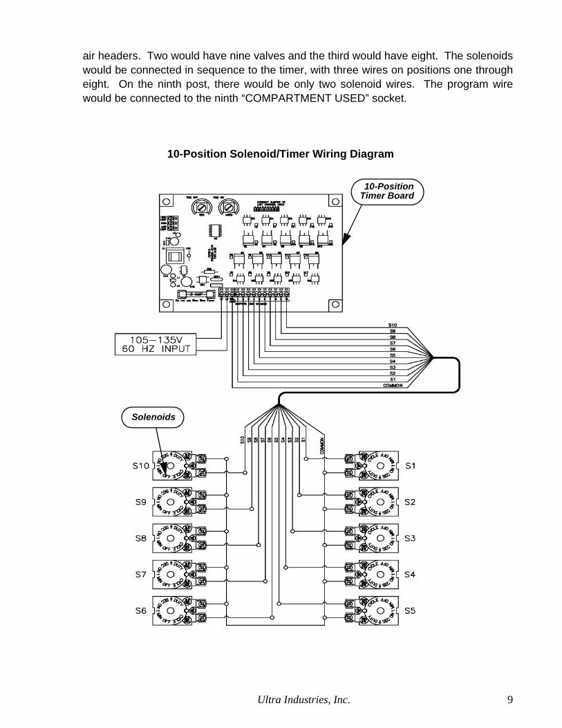
air headers. Two would have nine valves and the third would have eight. The solenoids
would be connected in sequence to the timer, with three wires on positions one through
eight. On the ninth post, there would be only two solenoid wires. The program wire
would be connected to the ninth “COMPARTMENT USED” socket.
10-PositionTimer Board
Solenoids
10-Position Solenoid/Timer Wiring Diagram

10 Ultra Industries, Inc.
Installation and Operation of the Photohelic™Differential Pressure Switch/Gauge
OperationThe Photohelic™ is used to control the reverse pulse jet cleaning of the dust collector based ona set range of the differential pressure across the Tube Sheet. When the differential pressurereaches the high set point on the Photohelic™ gauge, a switch is thrown which turns on thetimer to start the cleaning process. This will continue until the differential pressure reaches thelow set point and the timer is turned off. In this way, the dust collector pulses on demand onlywhen it is required and eliminates wasteful consumption of compressed air.
Location/MountingSee Mounting The Differential Pressure Gauge for connection of the tubing.
WiringThe Photohelic™ Gauge comes pre-wired and installed in a NEMA 4X fiberglass box. You willbe required to connect 115 Volt, single phase, 60 Hz power to the “L1” and “L2” terminals on thewiring diagram. You will also need to connect a dry circuit between the “NO” (Normally Open)and “C” (Common) Photohelic™ switch terminals and the timer “pressure switch” terminals.Make sure that the jumper which is across the “pressure switch” terminals is removed beforemaking this connection.
ELECTRICAL HAZARD! Use extreme caution when handling highvoltage wires and make sure all electrical enclosures and equipmentare properly grounded.

Ultra Industries, Inc. 11
AdjustmentThere are two hand knobs on the front cover of the gauge. The right hand knob is the high setpoint and the left hand knob is the low set point. There is a corresponding red needle indicatorthat is visible through the gauge cover to show where your current setting is located. We recom-mend that the differential pressure settings for the gauge be set to a high set point of 5-6” W.C.and a low set point of 3-4” W.C. Please note that the settings on the timer should be adjusted toan “OFF-TIME” of 5-10 seconds to allow the timer sequence to pulse all rows before the differ-ential pressure reaches the low set point.
FIBERGLASS BOXNEMA 4X
RED INDICATOR NEEDLEHIGH SET POINT
RED INDICATOR NEEDLE
LOW SET POINT
BLACK NEEDLEINDICATOR -
DIFFERENTIALPRESSURE
LOW SET POINT
LEFT HAND
RIGHT HAND
HIGH SET POINTKNOB
KNOB

12 Ultra Industries, Inc.
Initial System Start Up
Auxiliary EquipmentInspect all equipment before start-up to see that there are no foreign objects in rotating
equipment and that safety equipment is in place.
Start the fan, screw conveyor and/or airlock and inspect for proper rotation and that all
equipment runs smoothly. After making the necessary corrections, turn all this equipment off.
Duct WorkSee that all connections are tight and that all cleanout ports are closed. The duct work must be
free from debris.
Starting The System1. All doors and ports should be closed, with timer and auxiliary equipment off. Turn on com-
pressed air to collector and inspect the system for leaks. If air is leaking from any blow pipewith the timer off, there may be a leak between the solenoid and diaphragm valve. Inspectthe ¼” OD tubing between the solenoids and the diaphragm valves to be certain that allconnections are tight and there are no leaks. The tubing must not be crimped. Shut off thecompressed air supply.
2. Turn on the timer. The red “POWER-ON” indicator should light up. Turn the “OFF-TIME”and “ON-TIME” screws fully counterclockwise. The individual timing lights should blink at1.5 second intervals and the corresponding solenoid valves will be activated. A “click”sound can be heard every time a solenoid activates.
3. Turn on the air supply to the air header. All solenoid valves should be operating and the
exhaust air from each valve can be felt by placing your finger over the exhaust port. Let thecollector pulse for ten minutes to clear all lines. Then, set the “OFF-TIME” between six andten seconds with 85 PSI(g) air supplied. Later, this may be adjusted to suit your collectionrequirements based on the dust loading.
4. Turn on all dust discharge equipment such as rotary valves, screw conveyors, etc.5. If water vapor or other condensates are present, it will be necessary to preheat the system
so that the surface temperature of the piping/ductwork and collector are above the dewpoint temperature. Dryers, coolers and some grinding systems are common examples.
6. Start the fan with the fan damper set at about half-flow and run for 30 minutes because it isgood practice to introduce the dust stream to a new bag at a reduced rate. This is particu-larly true when very fine dust (less than 2 microns) or high concentrations are present.
7. Observe the differential pressure gauge. At start-up, the differential pressure (pressuredrop) will be low. After thirty minutes of operation, the bags will start to be coated, the filter-ing efficiency will increase and the differential pressure will start to rise. At this time, the fandamper should be opened to the design setting.
NOTE: On systems that use 1-1/2” diaphragm valves, the “ON-TIME” must not be set lower than 0.10 seconds.

Ultra Industries, Inc. 13
8. When the collector has stabilized (may require eight hours of operation) the differentialpressure should remain steady at some value between 1” and 6” Water Column/Gauge. Werecommend that the differential pressure be maintained at 4” W.C. If it is below 4”, gradu-ally increase the “OFF-TIME” until it reaches 4” W.C. If it is over 4”, the “OFF-TIME” shouldbe decreased until it reaches 4” W.C.
9. The temperature of the system must be controlled to remain below the maximum tempera-ture capability of the filter bags.
10. The collector is now ready for use.
NOTE: Never Allow the differential pressure across the bags toreach above 15” W.C. At this pressure, bag cages will start tocollapse.

14 Ultra Industries, Inc.
Using Your Collector
Standard Start-UpSubsequent start-ups should begin with all systems off. Exception: After new bags are
installed, follow Initial System Start Up procedure. Turn on in the following sequence:
1. Filter bags & cages installed, all ports, access doors and rotating equipment closed withsafety equipment (belt guards, etc.) in place.
2. Turn on compressed air.
3. After pressure reaches 85-100 PSI(g), turn on the timer.
4. Turn on all dust discharge equipment.
5. Turn on the fan. Preheat the system if necessary.
6. If the collector discharge is visible, refer to the Trouble Shooting Check List.
Shutting Down Your CollectorDust control and pneumatic conveying systems Reverse start-up procedure. First, turn off
the fan, wait five to ten minutes and turn off the timer and discharge (auxiliary) equipment.
Process Systems Dryers and the system to the collector discharge should be run until empty
and heat maintained at a reduced rate until the collector metal surfaces and filter bags are dry.
Then proceed as above.
Routine MaintenanceInspections
Frequency will vary as widely as there are operating conditions. Your experience will be the
best guide. In general, proceed as follows:
1. Daily adjust the timer “OFF-TIME” to achieve a differential pressure of 4” W.C.
2. Weekly check timer, solenoid valves and diaphragm valves for proper operation. Usuallylistening to determine that there is a uniform time interval between diaphragm valve airdischarge blasts will suffice.
3. Monthly lubricate fan, rotary valve and screw conveyor. Inspect theseals on the airlock and screw conveyor for dust leakage. Refer to therespective IOM manual for instructions.
4. Quarterly inspect filter bags for condition.
5. Inspect, clean and replace air supply and differential pressure gauge filters as operatingconditions require.

Ultra Industries, Inc. 15
Safety
Before entering the dust collector:
1. Run cleaning system for 20 minutes with the fan turned off to clean off the filter bags.
2. Run collected solids out of the hopper.
3. Lock out electrical power on all rotating equipment.
4. If toxic gasses and/or solids are present, purge collector housing with fresh air and block
off inlet duct. Refer to plant safety confined space entry procedures.
5. Install catwalks and safety cables.
6. Secure access doors in open position or remove doors by lifting from the hinge pins.
7. Use buddy system.
8. Wear a respirator as required.
9. Use common sense.

16 Ultra Industries, Inc.
Trouble Shooting Check ListProblems with Probable Causes
First be sure that you have followed the complete Standard Start-Up procedure.
Visible Exhaust Dust Loss
1 Missing bag. Dust loss will be constant and not in synchronization with diaphragm valveblasts. Locate and replace the missing bag.
2. Improperly installed bags. Side removal bags with loose clamps or top removal bags withloosely seated snap bands in the tube sheet hole. Reinstall the filter bags and cages prop-erly.
3. Holes in bags. Caused from mechanical damage during installation, abrasion, thermal orcorrosive attack or wear. Replace worn or damaged bags with bags made from filter mediasuitable for the application.
4. Dust in the clean air plenum after bags fail. Always clean the plenum before installing newfilter bags.
5. Filter bags are not efficient for the application and the dust passes through the filter media.Contact Ultra Industries, Inc. for alternate bag selection.
Insufficient Air Pressure
6. Compressed air piping leaks. Tighten all fittings.
7. Additional usage from plant compressed air system. Revise system to furnish adequate airsupply.
Entire Row Of Bags Inadequately Cleaned
8. Debris in diaphragm valve. Disassemble valve and gently clean the inside of the valve aswell as the plastic seat on the underside of the diaphragm.
9. Dirt in the solenoid valve plunger. Remove the solenoid cover and clean the plunger. Note:Be careful not to lose the spring which may pop out as you remove the plunger.
10. Solenoid valve inoperative. Electric, solenoid or timer fault. Establish power to the sole-noid and proper wiring to the timer. Check solenoid and if alright, change wiring at the timerto the next unused terminal and move the program wire to the highest numbered terminalused. If this is not desired or no other terminals are available, replace the timer. If the sole-noid is defective, replace.
Random Bag Inadequately Cleaned
11. Debris in air distribution pipe hole. Remove debris either by inserting a small rod into thehole or by removing the air pipe and flushing it out.

Ultra Industries, Inc. 17
High Differential Pressure
12. Excessive air flow. Adjust fan damper until differential pressure gauge indicates the properpressure.
13. Compressed air pressure is below 75 PSI(g). See paragraphs 5 & 6.
14. Solenoids skipping. See paragraph 9.
15. Leakage through rotary valve. Check rotary valve for wear or damageand correct.
16. Dust on inside of bags after previous bag failure. Clean the plenum andthe inside of the filter bags. See paragraph 4.
17. Blinding (Plugging) of the bags due to condensation. Change operations upstream so thatliquids remain vaporized through the dust collector. It may be necessary to insulate the col-lector. Usually operating the collector with no solids flowing through will permit recoveryand removal of condensation.
18. Re-entrainment of dust due to hopper overloading, bridging or plugging. Run out dust fromdischarge system with the fan off. Consider increasing the capacity of the discharge sys-tem or reducing the load. Install hopper vibrators and/or fluidizers.
19. Improper timer sequence. Inspect the timer for proper solenoid wiring and program wireposition.
20. Defective Timer. Return timer to be repaired or replaced.
21. Bags too tight. If bags were cleaned, they may have shrunk and are too tight to permitproper flexing. Replace with new filter bags.
Improper Pulsing
22. Solenoid valves not working. See paragraph 9.
23. Continuous air flow through diaphragm valve. See paragraphs 7 & 8. Leak in tubingbetween solenoid and diaphragm valve. Tighten connections and replace tubing if neces-sary.
24. Insufficient Dust Collection (System Volume Too Low)
25. Fan running backwards. Correct fan rotation.
26. High differential pressure. See paragraphs 5 through 9 and 16 through19.
27. Fan belt slippage. Tighten or replace belts.
28. Air leakage between collection pick-ups and fan. Seal any leaks andtighten all flanged connections in duct work.
29. Additions to dust collection system. Increase system capacity

18 Ultra Industries, Inc.
Short Bag Life
30. High Temperature. Bleed in ambient air and/or replace filter bags with higher temperatureresistant filter media.
31. Chemical attack. Contact Ultra for recommendations.
32. Localized wear from rubbing. Straighten cages so that bags do not rub against each otheror against the collector housing. Replace worn bags & cages. Wear near the material inletmay require an inlet baffle.
Timer Malfunction
33. “Power-On” indicator light not on. Ascertain that timer “ON/OFF” switch is on, that timerwiring is connected and that indicator bulb is good. Inspect for blown fuse. Replace with 3amp, 3 AG fuse. Do not use slow blow type.
34. Solenoids skipping. See paragraph 9.
Unusual Differential Pressure Gauge Readings
35. Unusual readings. Inspect gauge filter and replace if plugged. Blocked gauge tubing.
Disconnect and remove blockage. If blockage occurs frequently, install filter and replace it
routinely.
Replacement PartsYour Ultra collector uses the finest components available. To ensure continued trouble freeoperation of your collector, we recommend that only factory engineered components be used.The following components are suggested to be kept on hand to maintain trouble free service:
1. A spare set of filter bags and bag clamps
2. Extra solenoid valves and diaphragm valves
3. A spare timer board for multi-collector installations.
Our collector components can be used to maintain peak performance of collectors
manufactured by other leading manufacturers.

Ultra Industries, Inc. 19
Common Assembly Diagrams
PULSE-JET MECHANISM 3/4”

20 Ultra Industries, Inc.
PULSE-JET MECHANISM 1”

Ultra Industries, Inc. 21
PULSE-JET MECHANISM 1-1/2”

22 Ultra Industries, Inc.
AIR HEADER ASSEMBLY 3/4”

Ultra Industries, Inc. 23
AIR HEADER ASSEMBLY 1”

24 Ultra Industries, Inc.
AIR HEADER ASSEMBLY 1-1/2”

Ultra Industries, Inc. 25

26 Ultra Industries, Inc.

Ultra Industries, Inc. 27

28 Ultra Industries, Inc.
1/8” NPT HIGH PRESSURE PORT
1/8” NPT LOW PRESSURE PORT
1/8” NPT HIGH PRESSURE OPTIONAL PORT
1/8” NPT PLUGS
#6-32 UNC HOLES ON 4-1/8” B.C. 120 APART
1/8” NPT LOW PRESSURE OPTIONAL PORT
OPTIONAL PORTS
PLUGGED
HOLD DOWNS
LOW PRESSURETO C.A.P.
HIGH PRESSURETO D.A.P.
1/2-13 UNC NUTS
1/2 LOCK WASHER
1/2 FLAT WASHER
BRACKET WELDED TO
SIDE OF COLLECTOR
#6 X 2” LONGSHEET METAL SCREWS
#6 UNC X 5/16” LONG
HOLD DOWNS
MAGNEHELIC™ MOUNTING BRACKET
1/2-13 UNC X 1-1/4” LONG
1/8” NPT TO 1/4 HOSE
MAGNEHELIC™ GAUGE
MAGNEHELIC™ GAUGE ASSEMBLY
Ultra Industries, Inc. 29
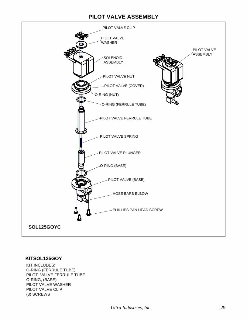
PILOT VALVE ASSEMBLY
KIT INCLUDES:O-RING (FERRULE TUBE)PILOT VALVE FERRULE TUBEO-RING, (BASE)PILOT VALVE WASHERPILOT VALVE CLIP(3) SCREWS
KITSOL125GOY
SOL125GOYC
SOLENOID
PILOT VALVE
PILOT VALVE CLIP
PILOT VALVE NUT
PILOT VALVE (COVER)
O-RING (NUT)
ASSEMBLY
WASHER
O-RING (FERRULE TUBE)
PILOT VALVE FERRULE TUBE
PILOT VALVE SPRING
PILOT VALVE PLUNGER
O-RING (BASE)
PILOT VALVE (BASE)
HOSE BARB ELBOW
PHILLIPS PAN HEAD SCREW
PILOT VALVEASSEMBLY

30 Ultra Industries, Inc.
NOTES
Ultra Industries, Inc. 31
NOTES

32 Ultra Industries, Inc.
Ultra Industries is a manufacturer of air
filtration and pneumatic conveying equip-
ment providing exceptional service and quality
for its customers.
Visit our website at www.ultradustcollectors.com
or email us at: [email protected]