Embed Size (px)
Citation preview

Installation
Operation
&
Maintenance
Manual
Rotary Piston Vacuum Pumps
Part No. 9983-0000-P02 Rev. C / April 2019

DEKKER Vacuum Technologies, Inc. / Part No. 9983-0000-P02 Rev. C 2
ROTARY PISTON VACUUM PUMPS
TABLE OF CONTENTS
CUSTOMER SERVICE 5
CONTACT INFORMATION 5 ORDER INFORMATION 5
INTRODUCTION 6
SAFETY 6
THEORY OF OPERATION 7
STORAGE 8
INITIAL FREIGHT RECEIPT AND INSPECTION 8
INSTALLATION 8
OVERVIEW 8 UNPACKING 8 LIFTING 8 LOCATION 9 MOUNTING 9 VENTILATION 9 ELECTRICAL PREPARATION 9 PIPE CONNECTION AND SIZING 10 INLET PIPING 10 DISCHARGE PIPING 10 COOLING WATER PIPING 11 COOLING CAPACITIES AND PORT SIZES 11
START-UP PROCEDURES 12
SHUT DOWN PROCEDURES 16
MAINTENANCE 17
PUMP BEARING LUBRICATION 17 MOTOR BEARING LUBRICATION (WHERE REQUIRED) 17 INLET FILTER (IF INSTALLED) 17 SEAL FLUID 17 OIL CHANGE PROCEDURE 18 STANDARD SYSTEM CAPACITIES 18 COMPLIMENTARY OIL ANALYSIS 19 GAS BALLAST VALVE(S) 19 OIL SOLENOID VALVE 19

DEKKER Vacuum Technologies, Inc. / Part No. 9983-0000-P02 Rev. C 3
SHAFT SEALS 19
MAINTENANCE SCHEDULE 20
DURING FIRST MONTH OF OPERATION 20 DAILY 20 EVERY 3 MONTHS 20 EVERY YEAR / ANNUALLY 20 EVERY 10,000 HOURS OF OPERATION 20 EVERY 5 YEARS 20
ACCESSORIES (IF INCLUDED) 21
TROUBLESHOOTING 22
START-STOP PROBLEMS 22 UNIT WILL NOT START 22 VACUUM PROBLEMS 22 UNIT OPERATES, BUT DOES NOT ACHIEVE DESIRED VACUUM LEVEL 22 OVERHEATING PROBLEMS 22 UNIT OVERHEATS OR OPERATES ABOVE 180°F 22 UNIT OVERHEATS ON START-UP IN LOW AMBIENT TEMPERATURES 22 NOISE AND VIBRATION PROBLEMS 23 THE UNIT IS MAKING AN ABNORMAL NOISE OR SOUND 23 UNIT IS VIBRATING EXCESSIVELY 23 OIL PROBLEMS 23 UNIT USES EXCESSIVE OIL OR PRODUCES AN OIL-MIST 23

DEKKER Vacuum Technologies, Inc. / Part No. 9983-0000-P02 Rev. C 4
THIS INSTALLATION, OPERATION, AND MAINTENANCE MANUAL MUST STAY WITH
EQUIPMENT.
PLEASE REGISTER YOUR EQUIPMENT WARRANTY AND START-UP RECORD ONLINE
AT WWW.DEKKERVACUUM.COM
DEKKER Vacuum Technologies, Inc. / Part No. 9983-0000-P02 Rev. C 5
CUSTOMER SERVICE
Contact information
935 SOUTH WOODLAND AVENUE, MICHIGAN CITY, IN 46360-5672
TEL.: 219-861-0661 – FAX: 219-861-0662 – TOLL-FREE: 888-925-5444
Bus. Hours: 7:30 a.m. – 4:30 p.m. CST
Website: www.DEKKERvacuum.com
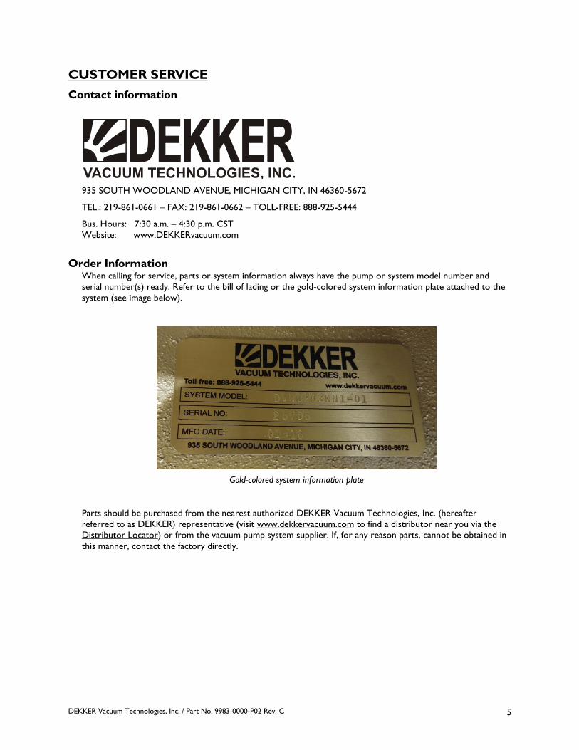
Order Information When calling for service, parts or system information always have the pump or system model number and
serial number(s) ready. Refer to the bill of lading or the gold-colored system information plate attached to the
system (see image below).
Gold-colored system information plate
Parts should be purchased from the nearest authorized DEKKER Vacuum Technologies, Inc. (hereafter
referred to as DEKKER) representative (visit www.dekkervacuum.com to find a distributor near you via the
Distributor Locator) or from the vacuum pump system supplier. If, for any reason parts, cannot be obtained in
this manner, contact the factory directly.

DEKKER Vacuum Technologies, Inc. / Part No. 9983-0000-P02 Rev. C 6
INTRODUCTION The DEKKER HullVacTM rotary piston vacuum pump has been designed for safe, reliable, trouble-free service,
provided the maintenance guidelines as set out in this manual are followed. Compared to other vacuum pump
systems, the HullVac rotary piston vacuum pump offers the advantages of low blank off pressures, high pumping
speeds at low pressures, and durability. These pumps are low maintenance and easy to use. However, a
vacuum pump is a rotating piece of equipment and operators must exercise good judgment and follow proper
safety procedures to avoid damage to the equipment or personal injury. Please review and follow all
instructions in this manual before attempting to install, start or operate the equipment.
SAFETY All vacuum pumps, systems and/or compressors (hereafter referred to as the Product) offered by DEKKER
have been designed and manufactured for safe operation. However, the responsibility for safe operation rests
with those who use and maintain these products. The safety department where the product is installed should
establish a safety program based on OSHA, federal, state, and local codes. It is important that due
consideration be given to hazards which arise from the presence of electrical power, hot liquids, harmful gases,
and rotating equipment. Proper installation and care of protective devices is essential to safe system operation.
These safety procedures are to be used in conjunction with the instructions contained in this manual.
WARNING: DO NOT PUMP OXYGEN or oxygen rich mixtures with these pumps -
EXPLOSION HAZARDS!

DEKKER Vacuum Technologies, Inc. / Part No. 9983-0000-P02 Rev. C 7
THEORY OF OPERATION The DEKKER HullVac rotary piston vacuum pump is designed and manufactured to achieve a high level of
performance. These pumps create a vacuum with a piston that moves in a circular path. As it rotates, pressure
is decreased on the inlet side and increased on the discharge side. The two sides are separated by a film of oil
between the piston and the cylinder. Once the piston makes a complete cycle, the clearance volume is
completely filled with oil, increasing the compression ratios within the pump. This design is what gives rotary
piston pumps their deep vacuum levels and durability. Depending on the application and desired vacuum level,
HullVac pumps are offered in single-stage or two-stage configurations. The two-stage pump can obtain a deeper
vacuum level because it utilizes two piston chambers in series.
Intake Stroke Discharge Stroke
Not suitable above 100 Torr Not suitable above 10 Torr

DEKKER Vacuum Technologies, Inc. / Part No. 9983-0000-P02 Rev. C 8
STORAGE Keep the system in a cool dry environment. Plug all open ports to keep out dirt and foreign objects. Every 2 - 3
months remove the belt guard and rotate the lower pulley 2 ¼ turns.
If the pump is to be stored in a location where freezing temperatures may be encountered, drain the water
jacket if applicable. The water jacket drain plugs are typically located on the exhaust side of the pump. Refill
with antifreeze for storage.
INITIAL FREIGHT RECEIPT AND INSPECTION Before a system ships from DEKKER, it is thoroughly tested, and will not be released unless it passes our
Quality Control standards. All pumps are thoroughly inspected and are not released unless they pass our
Quality Control standards. Once the product is received and signed for in Good Condition, DEKKER cannot
be held accountable for undiscovered, unclaimed damage that is a result of freight transit. It is the responsibility
of the receiver to thoroughly inspect and test the product for functionality upon delivery. The customer should
take photos of the product as it arrives and send to DEKKER and the freight carrier if there are any issues. The
party who selected the shipper is responsible for filing the freight claim. Failure to report these issues within
the freight carriers’ undiscovered damage window can result in non-acceptance of freight claims. DEKKER does
keep photos of all systems, as shipped, to assist in freight claims. Report any damage immediately to the factory.
Key items to inspect:
Is the product received as requested? Are all parts, accessories, and components delivered?
Was the skid or crating received in good condition? Check for cosmetic damage.
Check wiring inside of control panel. Are all wires should be terminated and connections tight? (If
applicable)
Check control panel components. Are they tight on DIN rail and/or other mounts/fasteners?
Are there any leaks or puddles around the pump? Specify hose, piping or housing leak.
System must be given an initial startup test as soon as possible after delivery. This is to ensure that the motor
has not shifted out of alignment during transit as well as to verify that electrical components are functioning
without fault – Variable Frequency Drive (VFD), Programmable Logic Controllers (PLC), panel cooling fans,
transducers.
INSTALLATION
Overview The design of the piping system, foundation layout, and plant location are the responsibility of the purchaser.
DEKKER Vacuum Technologies, Inc. and its representatives may offer advice, but cannot assume responsibility
for operation and installation design.
Please consult the factory or a specialist skilled in the design of plant layout, system piping design, and
foundation design. The installer should carefully read this manual before installing the equipment. DEKKER or
your authorized dealer can provide start up assistance in most instances for a fee. Contact DEKKER for
hourly/daily service rates.
Unpacking Upon receipt of pump or system, immediately inspect for signs of damage. Carefully remove packing or crating
from around pump or system. Be sure to keep equipment in upright position.
Lifting Lift the equipment carefully and with weight evenly distributed. DEKKER is not responsible for equipment that
has been damaged through mishandling or dropping.

DEKKER Vacuum Technologies, Inc. / Part No. 9983-0000-P02 Rev. C 9
Location Install the unit in a well ventilated and dust free area. The pump or system should be a minimum distance of 3
feet from surrounding walls to allow for checking fluid level, temperatures, pressures and general servicing.
Mounting The pump or system must be installed on a level surface in the horizontal position. The foundation must be
designed to support the total unit weight, without any settlement or crushing, be rigid and substantial enough
to absorb any equipment vibration, maintain true alignment with any drive mechanism, and must permanently
support the system baseplate at all points. The vacuum system must be leveled and secured with anchor bolts.
Anchor bolts must be of adequate size to withstand the mechanical stresses exerted on it.
Systems 50 HP and larger should also be grouted into position per local codes. The foundation should be
constructed to allow for ¾ to 1-½ inch of grout. The baseplate is set on shims and the grout is poured
between the foundation and the baseplate. To have the required body to support the baseplate, grout should
be at least ¾ inch thick.
The number and location of shims will be determined by the design of the baseplate. Firm support should be
provided at points where weight will be concentrated and at the anchor bolt locations. Use enough, and large
enough, shims to provide rigid support. Baseplates are usually designed with openings to allow pouring grout.
When the baseplate has been shimmed, leveled, and the anchor bolts have been snugly tightened, a dam is
constructed around the foundation to contain the grout. The dam level should be at least ½ inch above the top
surface of the shims. Grout should be poured inside and around the outside of the baseplate and leveled. Allow
the grout to dry for a minimum of 48 hours before tightening the anchor bolts.
Please note that the pump/motor coupling and V-belt units will need to be realigned prior to start-up, with
the exception of monoblock units.
Ventilation Locate the unit in an area with sufficient airflow and accessibility. To prevent excessive ambient temperature
rise, it is imperative to provide adequate ventilation. Cooling is an important aspect of reliable equipment
operation and it is therefore important to install the unit in a reasonably cool area where the temperature does
not exceed 104°F (40°C). For higher ambient temperatures contact the factory.
Typical system operating temperature is between 140°-185°F. Minimum oil temperature should not be below
45°F.
Electrical Preparation All system wiring is performed at the factory if a control panel is supplied and installed on the skid. Check area
classification to ensure all electrical enclosures comply with code. Required customer wiring is minimal, but
should be done by a qualified electrician in compliance with OSHA, National Electric Code and any other
applicable local electrical code concerning switches, fused disconnects, etc. DEKKER includes a wiring diagram
in the control panel for use by the installer. DEKKER recommends a main disconnect switch be fitted between
the vacuum system and the incoming power.
Check the line voltage to make sure it matches the vacuum system voltage. The voltage should be within the
tolerance as specified by motor manufacturer or to local code.
All HullVac pumps are equipped with an oil flow solenoid valve that prevents oil from entering the pumping
chamber when the pump is not in use. The oil flow solenoid coil voltage typically matches motor voltage. The
solenoid valve coil is energized whenever the motor is energized. During initial operation, confirm valve
operation by holding a screwdriver, or other metal object, close to but not touching the valve stem top. If the
coil is energized, a gentle tugging or vibration will be detected. An oil stream will also be present on the oil
level site port whenever the pump is in operation. If an oil stream or splash is not present, check the solenoid
valve for proper operation.
Check the system for proper motor rotation by jogging the motor. The direction of rotation is marked by an
arrow on the motor or pump housing. If the rotation is incorrect, switch any two of the three main power
leads (three phase power) on the contactor inside the control panel. Failure to do so could result in serious
equipment damage.

DEKKER Vacuum Technologies, Inc. / Part No. 9983-0000-P02 Rev. C 10
WARNING: Install, ground, and maintain equipment in accordance with the National Electrical
Code and all applicable federal, state and local codes.
Pipe Connection and Sizing Before installation, remove all protective inserts on the pump suction and discharge. Piping connected to the
system must be installed without imposing any strain on the system components. Improperly installed piping
can result in misalignment, general operating problems, and pump failure. Use flexible connectors and vibration
isolators where necessary. Piping must be cleaned of debris before installation.
Inlet Piping Note: Install a temporary screen at the pump inlet flange at first start-up to protect the unit against carryover
of pipe debris and welding slag. The screen must be removed after the initial start-up period.
Inlet piping must be welded steel that is vacuum rated and should be at least the size of the pump inlet. Install
the unit as close as possible to the process to minimize losses due to the length of the inlet piping. If the unit
has to be installed further away from the process, be sure the inlet piping is properly sized to minimize the
overall line pressure drop. For more information consult the factory.
If the inlet gases contain dust or foreign particles, a suitable 5 micron (or finer) inlet filter should be installed at
the inlet port. For more information consult the factory. A vacuum rated isolation valve should be installed for
routine blank-off performance testing and servicing.
Discharge Piping DEKKER recommends, as a minimum, CPVC discharge piping as discharge temps may exceed +170°F. CPVC is
rated for 200°F max, and PVC is only rated for 140°F max. Discharge piping must be at least the size of the
pump exhaust port. Discharge piping should be routed outside or to a properly sized coalescing filter. Install a
drip leg with a tee on the discharge line to prevent condensables from draining back into the pump. See the
“Discharge Piping Diagram” as shown below. The drip leg volume should be such that it is unlikely to fill with
condensate between routine draining.
No flow restriction should be present in the discharge piping. Discharge flow restrictions lead to excessive
power consumption at high inlet pressure as well as overheating which may cause damage to the pump.
Discharge Piping Diagram

DEKKER Vacuum Technologies, Inc. / Part No. 9983-0000-P02 Rev. C 11
Cooling Water Piping For water-cooled units, it is necessary to check cooling water supply. A proper, consistent water flow must be
maintained for adequate cooling. Refer to the Cooling Capacities and Port Sizes table below for recommended
cooling water capacities at 60°F based on standard operation. Water jacket pressure must not exceed 30 psig.
Normal operating temperature is between 140°-160°F as measured on the oil solenoid valve body located
below the exhaust port. Unit casing temperature should not exceed 180°F. If excessive temperature is
measured, increase the cooling water flow. Maximum cooling water supply temperature should not exceed
85°F.
Oil temperature should be maintained at 165°F. Minimum oil temperature should not be below 55°F. The
increased sealing oil viscosity caused by low temperature can lead to internal galling and motor overload.
Water-cooled units require an adequate supply of cooling water at 60°F and a maximum supply pressure of 30
psig. If the cooling water temperature or available pressure is higher, consult your authorized dealer or the
factory.
The cooling water outlet connection of the heat exchanger may be fitted with an optional water miser valve,
which regulates the cooling water flow rate depending on pump operating temperature. To raise the operating
temperature, turn the valve-adjusting screw counter-clockwise when viewed from the top. To lower operating
temperature, turn clockwise.
Cooling Capacities and Port Sizes
Pump Pump CFM HP Air Cooled
Cooling Water
Capacities
(gpm)
Cooling Water
Port Sizes
(Inch – NPT)
HV55A 52 3 X - -
HV140A 130 5 X - -
HV160 150 7.5 - 1.5 1/2
HV412XT 300/340 10/15 - 2.5 1/2
HV450 450 20 - 3.5 3/4
HV635 635 30 - 5 3/4
HV850 850 40 - 7 1
HVC35A 32 3 X - -
HVC65 65 5 - 1 1/2
HVC100A 95 5 X - -
HVC180 180 10 - 2 1/2
HVC340 340 20 - 2.5 1/2

DEKKER Vacuum Technologies, Inc. / Part No. 9983-0000-P02 Rev. C 12
START-UP PROCEDURES
1 Ensure all shipping plugs and/or paper covers are
removed from the unit and tagging information is
followed for successful startup.
2 Remove the belt guard and rotate the pump two
complete revolutions by hand in the counterclockwise*
direction. This will clear accumulated oil from the
pump housing that can collect during long inactive
periods. Reinstall the belt guard.
*Rotation is clockwise on the HV412XT
3 For units utilizing V-belt drives, make sure the sheaves are
properly installed and aligned before attempting to
tension the drive. The V-belts should be placed over the
sheaves and in the grooves without forcing them over the
sides of the grooves. The tensioning steps below can be
used for all types of V-belts, all cross sections and number
of belts and all types of construction.
Avoid excessive heat (140°F and higher); belt life will
be shortened. Never switch or mix belts from one
groove to another on the sheaves. Do not use belt
dressing. Sheaves should remain free of oil and grease.
When replacing belts install an identical set.
For more specific V-belt tensioning guidelines consult
factory.
Sheave alignment should be checked by placing a straight
edge or tight cord across the sheave faces so that it
touches all four points of contact. Ordinarily, a
misalignment of more than one-half of one degree (one
eighth inch in one foot) will adversely affect belt life.
Improper sheave alignment produces uneven wear on one
side of the belt, causes the belt to roll over in the sheaves
or throws the entire load on one side of the belt,
stretching or breaking the cords on that side.
Tensioning a Drive - General Rules of Tensioning
1. Ideal tension is the lowest tension at which the belt
will not slip under peak load conditions.
2. Check tension frequently during the first 24-48 hours
of run-in operation.
3. Over tensioning shortens belt and bearing life.
4. Keep belts free from foreign material which may
cause slip.
5. Make V-Drive inspection on a periodic basis. Tension
belt when slipping. Never apply belt dressing as this
will damage the belt and cause early failure.
If the unit is idle for an extended period of time, the
tension on the belts should be removed.
Simple Tensioning Procedure
1. Measure the span length.
2. At the center of the span apply a force
(perpendicular to the span) large enough
to deflect the belt 1/64”, for every inch of
span length. For example, one deflection of
a 100 inch span would be 100/64 or 1-9/16
inches.
3. Compare the force you have applied with
the values given in Table 3.1 on the next
page. If the force is between the values for
normal tension and 1-1/2 times normal
tension, the drive tension should be
satisfactory. A force below the value for
normal tension indicates an under
tensioned drive. If the force exceeds the
value for 1-1/2 times normal tension, the
drive is tighter than it needs to be.
4. After the proper operating tension has
been applied to the belts, double check the
following: A) Parallel position of the
sheave shafts. B) Correct alignment of
sheave grooves.
Tensioning rules and procedure
courtesy of Dodge PT Manual MN-
4002

DEKKER Vacuum Technologies, Inc. / Part No. 9983-0000-P02 Rev. C 13
3.1
Tensioning Table
V-Belt
Section
Small Sheave Deflection Force (lbs)
For Drive Speed Ratios of:
Speed Range (RPM) Diameter (in) 1.0 1.5 2.0 4.0+
A
1800-3600 3.0 2.0 2.3 2.4 2.6
1800-3600 4.0 2.6 2.8 3.0 3.3
1800-3600 5.0 3.0 3.3 3.4 3.7
1800-3600 7.0 3.5 3.7 3.8 4.3
B
1200-1800 4.6 3.7 4.3 4.5 5.0
1200-1800 5.0 4.1 4.6 4.8 5.6
1200-1800 6.0 4.8 5.3 5.5 6.3
1200-1800 8.0 5.7 6.2 6.4 7.2
AX
1800-3600 3.0 2.5 2.8 3.0 3.3
1800-3600 4.0 3.3 3.6 3.8 4.2
1800-3600 5.0 3.7 4.1 4.3 4.6
1800-3600 7.0 4.3 4.6 4.8 5.3
BX
1200-1800 4.6 5.2 5.8 6.0 6.9
1200-1800 5.0 5.4 6.0 6.3 7.1
1200-1800 6.0 6.0 6.4 6.7 7.7
1200-1800 8.0 6.6 7.1 7.5 8.2
Tensioning Table and installation image courtesy of Dodge PT Manual MN-4002
Notes:
1. Use approximately 130% of above values to tension a new set of belts.
2. Use closest sheave diameter for sizes not shown.

DEKKER Vacuum Technologies, Inc. / Part No. 9983-0000-P02 Rev. C 14
4 Install a blank off flange to the inlet port or attach to a
sealed vacuum chamber. Make certain the pump is
attached to a closed system.
The discharge must be open to atmosphere during
startup. Excessive motor load characterized by low
rotation speed can be experienced if the discharge is
closed.
Repeated efforts to start the pump when the discharge
is not open to atmosphere may result in motor and/or
control system damage.
5 Jog the motor briefly and check direction of rotation.
The correct direction of rotation is marked by an
arrow on the motor or pump housing. If direction is
incorrect switch any two of the three leads at the
power connection. The correct direction of rotation is
counterclockwise facing the pump from the drive end
and clockwise if viewed from the non-drive end.
*Rotation is Clockwise on the HV412XT
6 Turn the cooling water on, if applicable.

DEKKER Vacuum Technologies, Inc. / Part No. 9983-0000-P02 Rev. C 15
7 Energize the motor – a slight belt slipping noise may
be heard as oil is pushed from the pumping chamber
through the valve deck. If the belt slip noise does not
stop within the first few seconds:
1. Stop the pump.
2. Disconnect the power.
3. Remove the belt guard.
4. Rotate the pump once by hand.
5. Tighten the belts if needed.
6. Reinstall the belt guard.
7. Reconnect power.
8. Restart.
8 Confirm the oil solenoid valve is open. The valve’s
solenoid coil is energized whenever the motor is
energized. During initial operation, confirm valve
operation by holding a screw driver or other metal
object close to, but not touching the valve stem top.
If the coil is energized, a gentle tugging or vibration
will be detected. An oil stream will also be present
on the oil level sight port whenever the pump is in
operation. If an oil stream or splash is not present,
check the solenoid valve for proper operation.
9 The oil level should be checked after the pump has
been operating at an inlet pressure below 1 torr for
5 minutes. Proper oil fill is confirmed when the sight
port oil level is at least ½ level. During initial
evacuation, the oil level may rise but will fall as the
pump operates below 1 torr.
During operation, oil should always be visible in the
sight port. Normal oil fill level is mid to two-thirds of
the sight port, throughout all operating conditions.
An oil fill level above the sight port should be
avoided as it will be difficult to verify correct fill level
and could damage the pump.
10 Check the voltage and motor current. They should
be within the specifications for the motor. Amperage
should be checked at the Overload.
Note: This test should also be performed under
normal system operating conditions.
DANGER: HIGH VOLTAGE!
Lethal shock hazard present.
USE EXTREME CAUTION!

DEKKER Vacuum Technologies, Inc. / Part No. 9983-0000-P02 Rev. C 16
11 After 15-30 minutes of operation, check pump
operating temperature, which should be in the 140°-
160°F range at the solenoid body. The casing
temperature will rise faster and be warmer at higher
suction pressures. During any operation, the casing
should not rise above 180°F.
SHUT DOWN PROCEDURES To stop the vacuum pump follow the procedure as outlined below.
1 Close the system inlet isolation valve
2 Push the STOP button or turn switch to the
OFF position.
3 Open the gas ballast valves to vent the
pump to atmosphere. If system is equipped
with an automatic vent valve or an anti-
suckback valve, no action is needed. Failure
to vent the pump to atmosphere may cause
oil to fill into the pumping chamber and
travel back through the inlet manifold into
the vacuum process chamber.
4 If water cooled, turn off the cooling water
supply.

DEKKER Vacuum Technologies, Inc. / Part No. 9983-0000-P02 Rev. C 17
MAINTENANCE
WARNING: Before attempting any maintenance such as changing the fluid, disconnect all power from the
system by switching off the main breaker, isolate all energy sources and allow system to cool.
Pump Bearing Lubrication Internal pump components do not require preventative maintenance. Bearings are self-lubricating type.
Motor Bearing Lubrication (where required) For information regarding motor bearing lubrication, refer to the motor maintenance and operation manual.
Inlet Filter (If Installed) Check after first 8 hours of operation. Clean or replace inlet filter element every 1000 to 3000 hours
depending on application or if excessive pressure drop is noticed. In some applications it may be necessary to
clean inlet filter more often. Clean filters by gently knocking off into a dust bin. Brush filter free of debris and
clean with a wet/dry vacuum cleaner. DO NOT USE COMPRESSED AIR TO CLEAN ANY FILTERS.
CAUTION: Be careful not to allow foreign material to fall in the pump suction opening when removing the
filter cartridge. Horizontal filter installation is recommended to prevent this. Filters must be disposed of
properly as they might contain toxic substances carried over from the process.
Seal Fluid The units are shipped with DEKKER’s specially formulated HullVac seal fluid (hereafter referred to as oil).
DEKKER recommends that this oil be used to obtain the optimal performance from the HullVac product and
to maintain the warranty period.
Oil should be changed whenever it appears white or yellow, foams consistently, or when dirty. Oil change
frequency depends on the materials being pumped. For clean applications, oil should be changed every 3000
operating hours or every 9 months, whichever comes first. For other applications, oil change could range from
once or twice a week or less dependent upon the type of process.
The most common contamination is water in the oil and can be recognized by a milky appearance visible in the
site port. Closing the pump inlet valve and operating the gas ballast valves for 2 to 4 hours can remove this
water. If this does not clear the oil, proceed to change it. In applications with consistent water accumulation,
draining the water from the reservoir prior to operation is recommended.
HullVac Oil
Container Size Water-Cooled Air-Cooled
1 Gallon Container 5120-0010-002 -
5 Gallon Container 5120-0050-000 5120-0050-004
55 Gallon Drum 5120-0550-000 5120-0550-001
Safety Data Sheets (SDS) available upon request.

DEKKER Vacuum Technologies, Inc. / Part No. 9983-0000-P02 Rev. C 18
Oil Change Procedure Run the pump until normal operating temperature is achieved. (140°-160°F as measured on the oil solenoid
valve). Run the pump for at least 1 hour prior to draining the oil. This will warm the oil to facilitate faster and
more complete draining. CAUTION: OIL WILL BE HOT!
Follow these steps to drain the oil:
Disconnect main power to pump.
Vent the inlet to atmosphere for 10 to 15 seconds. This will force the oil from the lower pumping
chambers into the upper reservoir.
Open the oil drain valve and allow the oil to drain completely.
Rotate drive belts by hand with the inlet open to atmosphere for 5 – 10 rotations. This will force
residual oil from the pumping chamber into the oil reservoir where it can be drained.
Follow these steps to fill with new oil:
Close the oil drain valve and fill the reservoir to two-thirds of the sight port by pouring oil through
the oil fill port located on top of the pump.
Reconnect main power to pump.
Close the inlet isolation valve so that the pump is blanked-off. Run the pump for 2-3 minutes. Check
the oil level.
Add oil until the sight port level is between mid to two-thirds level in the sight port. If overfilled, open
drain to drain off excess and re-run unit to confirm oil level.
The approximate oil capacities are given in the Standard System Capacities table below.
Standard System Capacities
System Capacity (gal)
HV55A 0.9
HV140A 3.3
HV160 4
HV340 10
HV412XT 12
HV450 13
HV635 15
HV850 25
HVC35A 0.9
HVC65 2.5
HVC100A 3.3
HVC180 6.5
HVC340 20
HVC960 48

DEKKER Vacuum Technologies, Inc. / Part No. 9983-0000-P02 Rev. C 19
Complimentary Oil Analysis DEKKER offers oil analysis to customers, regardless of the age of their system, at no charge. Collect
approximately 4 fluid ounces from the machine, and secure it in any type of clean bottle. On the bottle or a
packing list, please include the following: system serial number, the type of oil, the run hours on the oil and
machine, and note any problems you are having with the system if applicable.
Also make sure to include your contact information with email address. After the analysis is complete,
DEKKER will provide a report of the condition of the oil, along with recommendations.
Send to:
DEKKER Vacuum Technologies, Inc.
935 S. Woodland Ave.
Michigan City, IN 46360
United States
ATTN: After Sales
Gas Ballast Valve(s) The purpose of the gas ballast is to enable condensable vapors to be discharged through the pump in order to
prevent oil contamination by allowing ballast gas to mix with condensable vapors. Properly applied, it works
well with water vapor and reasonably well with some other condensable vapors. The drawback of using the gas
ballast is that it will limit the ultimate vacuum the pump can attain.
To engage, open the valve(s) depending on the degree of ballasting required to clear the condensable
contamination from the oil supply. There will be a slight change in the sound of the pump and the base
pressure will rise slightly. Excessive heat can be generated when the valve(s) are open and care must be given
to ensure adequate ventilation/cooling water flow. Be sure the pump body temperature does not exceed 180°F
as measured on the casting surface below the sight port.
Oil Solenoid Valve The oil solenoid valve is typically located under the exhaust port and prevents oil from filling into the pumping
chamber when the pump is turned off or when there is a power failure. It is critical that this valve operates
properly. If the valve malfunctions in an open position, oil will flow back into the pumping chamber when the
pump is shut off. This will result in hard starting, excessive belt wear, and possible equipment damage.
If the valve is stuck in the closed position, poor vacuum performance will result. If the pump is operated for
longer than a minute without oil, internal damage may occur. The condition of the solenoid valve interior will
mirror the condition of the oil reservoir housing. If there is a buildup of sludge, varnish, or particulate in the oil
reservoir, the solenoid valve body may be likewise contaminated.
Shaft Seals The pumps are equipped with lip seals and do not require preventative maintenance.

DEKKER Vacuum Technologies, Inc. / Part No. 9983-0000-P02 Rev. C 20
MAINTENANCE SCHEDULE To help ensure trouble free operation, a basic maintenance schedule consisting of the following system checks
is recommended.
During First Month of Operation Check belt tension weekly.
Verify tightness of pump mounting bolts weekly.
Torque the side cover bolts at the end of first month of operation.
Side Cover Bolt Torque Value
BOLT SIZE FT-LBS
M5 3
M6 5
M7 8
M8 12
M10 24
M12 40
M14 65
M16 100
Daily Check oil level daily - oil level should be between mid to two-thirds level in the sight port while in
operation.
Check pump temperature daily - casing temperature should not exceed 180°F.
Every 3 Months Check belt tension.
Verify tightness of pump mounting bolts.
Every Year / Annually Remove the oil reservoir access plate. Clean and inspect the sump for signs of metal filings that may be an
indication of excessive internal wear. Strain the oil through a mesh bag to inspect for particulates.
Remove the oil / air separator and the valve deck cover. Verify the valves are intact and free to move up
and down. Examine for signs of excessive wear.
If needed, replace the valve deck springs and wear plates.
Examine the belts for signs of excessive wear and replace as needed.
Verify if motor lubrication is required for pump motor.
Every 10,000 Hours of Operation Check coupling element for wear, if applicable. Replace if worn.
Clean strainer in seal fluid line.
Check belt tension, if applicable.
Every 5 Years Replace the bearings, shaft seals, shaft seal wear sleeves, and o-rings.
Replace the oil flow solenoid valve wear components.
Replace the gas ballast valves.
DEKKER Vacuum Technologies, Inc. / Part No. 9983-0000-P02 Rev. C 21
ACCESSORIES (IF INCLUDED) The following accessories are available for HullVac rotary piston vacuum pump systems:
Automatic Inlet Vent Valve (optional): Includes a normally open solenoid valve and filter
assembly mounted to the pump inlet port. When power is shut off, the pump inlet and manifold will
be vented to atmosphere. This will prevent accidental oil backflow into the manifold and process
chamber and will also vent the chamber up to atmosphere.
Automatic Inlet Isolation Valve (optional): Consists of a pneumatically actuated ball valve
mounted on the pump inlet that automatically closes whenever power is shut off.
NOTE: This includes the automatic inlet vent valve.
Temperature Control Valve (optional): Reduces cooling water flow by up to 90% while it
controls pump operating temperature within the optimal range of 140°-160°F. This temperature
optimizes water and solvent evaporation from the oil supply while preventing damage due to excessive
heating.
Inlet Filter (optional): Traps particulate larger than the internal clearances of the pump (5 micron).
Must be installed horizontally.
Oil Mist Eliminators (optional): Strips atomized oil droplets from the exhaust stream, reducing
the appearance of smoke. The assembly comes complete with a ball valve on the canister drain and a 0
to 15 psig gauge to monitor filter element condition.

DEKKER Vacuum Technologies, Inc. / Part No. 9983-0000-P02 Rev. C 22
TROUBLESHOOTING The following is a basic troubleshooting guide and not all options may be included. Service should be done by a
DEKKER authorized distributor or a properly trained service technician. Each unit is tested and checked at the
factory. Always indicate model and serial number when calling. The model and serial number is viewable on the
gold-colored information plate attached to the unit.
WARNING: Before attempting any maintenance such as changing the fluid, disconnect all power from the
unit by switching off the main breaker, isolate all energy sources and allow unit to cool. All electrical work
should be done by a qualified electrician in compliance with OSHA, National Electric Code and any other
applicable local electrical code.
Start-Stop Problems
Unit will not start 1. Check that the main AC power disconnect is ON and supplying power to the unit.
2. Check if the disconnect or circuit breaker is switched on.
3. Check the overload setting on the starter.
4. Ensure that the proper voltage is supplied and that the wire size is correct.
5. Check if the pump has seized by removing the belt guard and rotating the belts by hand (disconnect
power first). If a rubbing noise or binding is observed, contact the factory.
Vacuum Problems
Unit operates, but does not achieve desired vacuum level 1. Stop unit and disconnect power.
2. Check if the inlet valve is open and inlet filter is clean.
3. Ensure that no lines are open to the atmosphere, causing loss of vacuum.
4. Check for leaks in piping systems using conventional leak detection methods.
5. Ensure that the oil level is correct.
6. Check if the oil solenoid valve is working.
7. Check if the motor rotation is correct. Rotation is marked by an arrow on the motor or pump
housing. If incorrect, switch any two of the three main power leads to the vacuum pump motor.
Overheating Problems
Unit overheats or operates above 180°F 1. Stop unit and disconnect power.
2. Check if the oil solenoid valve is working.
3. Ensure that the oil level is correct.
4. Verify cooling water flow, if applicable.
5. Verify ambient air temperature is 104°F or below.
Unit overheats on start-up in low ambient temperatures 1. Stop system and disconnect power.
2. Verify oil temperature. Oil tends to thicken in temperatures of 55°F and below.

DEKKER Vacuum Technologies, Inc. / Part No. 9983-0000-P02 Rev. C 23
Noise and Vibration Problems
The unit is making an abnormal noise or sound 1. Stop unit and disconnect power.
2. Check belt tension and alignment.
3. Ensure that the oil level is correct.
4. Check the inlet filter and clean if necessary.
5. Check if the inlet valve is closed.
Unit is vibrating excessively 1. Stop unit and disconnect power.
2. Check belt tension and alignment.
3. Check if unit is properly supported. An uneven foundation can cause vibration problems.
4. Check that the mounting bolts of pump are not loose. Tighten as required.
Oil Problems
Unit uses excessive oil or produces an oil-mist 1. Ensure that the unit is pulling a deep vacuum level (deeper than 100 torr for single-stage and 10 torr
for two-stage).
2. Stop unit and disconnect power.
3. Confirm oil level is not too high.
4. Confirm the unit is using factory recommended oil.
5. Ensure that discharge piping is arranged correctly.