Embed Size (px)
Citation preview

Installation Operation
Maintenance682 Seal Cooler
®
Experience In Motion
Shell and tube system meets or exceeds the seal cooler requirements stated in the 4th Edition of API Standard 682

Design Overview Figure 1
2
Description682 Seal Coolers are shell and tube systems used with single or dual mechani-cal seals to lower the temperature of process or barrier fluid passing through the tube while cooling water passes through the shell. Units are factory configured for series or parallel flow through the tube; use this guide to properly apply and operate either flow plan.
The images of parts shown in these instructions may differ visually from the actual parts due to manufacturing processes that do not affect the part function or quality.
cover
fitting
outer shellcover
bafflebafflebaffle
inner shell inner cooling coil tubing
outer cooling coil tubing
Note: External tubing that configures series or parallel flow is not shown.

3
Product SpecificationsStandard Materials:
• O-rings Fluoroelastomer
• Tubing 316 Stainless Steel
• Fittings 316 Stainless Steel
• Shell and Covers 316 Stainless Steel
Technical Data:
• Cooling Coil Tube OD 19 mm (0.750 inch)
• Cooling Coil Tube Wall Thickness 2.4 mm (0.095 inch)
• Effective Cooling Area 0.51 m2 (5.50 ft2)
• Shell (Coolant) Flow Rate 24.6 to 75.7 l / min (6.5 to 20 gpm)
• Tube (Product) Flow Rate 7.6 to 37.9 l / min (2 to 10 gpm)
• Unit Weight (Empty) 62.1 kg (137 lbs)
• Maximum Temperature (Tube Side) 371°C (700°F )
• Maximum Temperature (Shell Side) 93°C (200°F), Canada 65°C (200°F)
• Max. Working Pressure (Tube Side) 255 Bar @ 371°C (3,700 psig @ 700°F)
• Max. Working Pressure ( Shell Side ) 17.9 Bar @ 150°C (260 psig @ 302°F)
Standard Model Numbers:
Series Tube Flow A2R21431-11 (Standard and CRN) A2R21431-26 (U-Stamp) B0355704 (PED 2014/68/EU)
Parallel Tube Flow A2R23812-16 (Standard and CRN) A2R23812-36 (U-Stamp) B0355703 (PED 2014/68/EU)
4
1 Installation
1.1 Primary Piping Plans
Plan 21 - Seal Flush Plan 21 provides cooling to the seal with high flush flow rate capabilities by recirculating pump discharge fluid through a flow control orifice and a seal cooler before it enters the seal chamber. Because the circulated fluid returns to the pump suction and must be re-pumped to discharge on each pass, the seal cooler is typically piped for Series or Multiple Pass Tube Flow to maximize heat transfer capability for continually removing both process fluid and seal generated heat. This piping plan is targeted for clean high temperature fluids and hot water under 80°C (176°F) to improve vapor margins, meet secondary seal element temperature limits, reduce coking and polymerizing, and/or improve fluid lubricity.
Plan 23 - Seal Flush Plan 23 cools the seal chamber fluid by using a pumping device to circulate the seal chamber fluid out through minimize head loss or pressure drop through this recirculation system, the seal cooler is typically piped for Parallel or Single Pass Tube Flow. The circulated fluid is isolated from the pump impeller area by a throat bushing so that the seal cooler needs to cool only the seal chamber fluid heated by seal generated heat and heat soak from the process side. This piping arrangement is the plan of choice for clean hot water services, particularly above 80°C (176°F) where water has low lubricity, and many clean hot hydrocarbons to improve vapor margins.
A 682 Seal Cooler piped for series tube flow is shown in Figure 2 and a 682 Seal Cooler piped for parallel tube flow is shown in Figure 3. Both Figure 2 and Figure 3 show the 682 Seal Cooler mounted either vertically as preferred or horizontally as may be required by some applications.

5
Series Tube Flow Piping Figure 2
Parallel Tube Flow Piping Figure 3
Horizontal Mount product vent
cooling water out
product drain
cooling water in
product vent
cooling water out
Vertical Mount(preferred)
product drain
cooling water in
0.9 m (3.0 feet) Maximum
0.45 to 0.60 m (1.5 to 2.0 feet)
0.9 m (3.0 feet) Maximum
0.45 to 0.60 m (1.5 to 2.0 feet)
Vertical Mount(preferred)
Horizontal Mount product vent
cooling water inproduct
draincooling water out
product vent
cooling water out
product drain
cooling water in

6
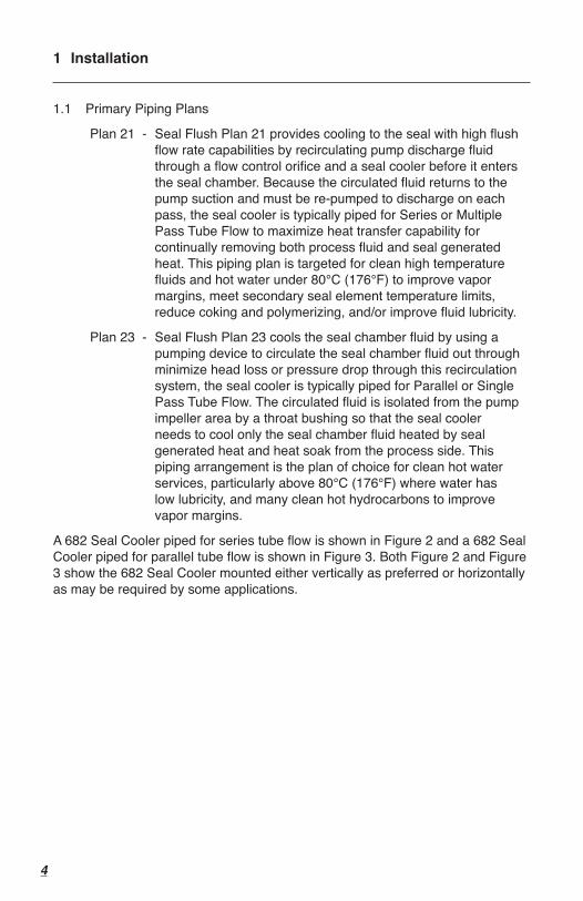
1.2 Vertical or Horizontal Mounting
Even though the 682 Seal Cooler can provide cooling capabilities when it is mounted horizontally, it is much more advantageous to mount this seal cooler vertically. In a vertical position, the cooling coil tubing winds gradu-ally downward and upward for optimum fluid drainage and gas/air venting.
In a horizontal position, it is much more difficult to totally drain both the sealing and cooling fluids. The sealing fluid becomes trapped within the lower turns of the cooling coil and the shell side cooling water becomes trapped below the lowest drainage point. The seal cooler would need to be removed and positioned vertically to achieve total drainage. It is also much more difficult to vent gas/air from a horizontal installation because the gas/air can become trapped within the upper turns of the cooling coil. A series of flush and bleed steps might be necessary in order to remove these trapped gases.
The presence of trapped gas/air is more critical when using a Plan 23 seal flush. Trapped gases that become entrained in the sealing fluid can reduce the seal cooler efficiency and flow in the seal flush circuit. This can ultimately cause the seal to overheat and fail due to a lack of lubrication. A vertically mounted seal cooler provides the advantage of a thermosy-phon effect which is lacking with horizontal installations to help alleviate these potentially detrimental conditions.
tube side gas vents
shell side gas vents (in cover)
cooling water drains
(in cover)
tube side fluid drains
Horizontal
Vertical
trapped gas in tubing
trapped gas in shell
tube side gas vent
tube side fluid
drains
7
It is strongly recommended that the 682 Seal Cooler be mounted in a vertical position whenever possible for a Plan 23 to ensure proper cooling efficiencies and simplify maintenance requirements. For applications that must conform to API Standard 682 requirements, the API Standard 682 specifies that the seal cooler must be mounted to allow complete draining and venting of both the cooling water and the process fluid. Vertical installations achieve this capability but horizontal mountings do not.
2 Operation2.1 When installing and again before start-up, ensure that the seal cooler,
piping, and vent locations provide complete venting of gas/air from both the tube and shell systems. This requires the vents to be located at the highest point in each system.
2.2 Before start-up, ensure that all the gas/air is vented from both the tube and shell systems to provide the system efficiencies expected and prevent a vapor lock condition.
2.3 When installing and again before start-up, ensure that the seal cooler, piping, and drain locations allow for drainage of fluid from both the tube and shell systems. This requires the drains to be located at the lowest point in each system. A drain valve (not just a plug) should be mounted in the shell system.
2.4 If the tube and shell systems can not be configured for both proper venting and proper draining, as with a horizontal installation, it is more important for proper venting to be achieved.
2.5 Before start-up, ensure that all piping is properly attached to the appropri-ate connections for both the tube and shell systems to prevent fluid leaks and achieve expected cooler efficiencies.
2.6 At start-up, ensure that the flush fluid flow and cooling fluid flow are set and stabilized at the prescribed flow rates determined for the application.
2.7 Do not allow the shell system cooling fluid flow rate to be operated below 24.6 L / min (6.5 gpm). Lower flow rates will encourage fouling which reduces the seal cooler heat transfer capabilities.
2.8 Cooler performance should be monitored periodically. Baseline tempera-tures should be gathered soon after equipment commissioning. Target shell side base line temperature differential should be 11°C (20°F) or lower. Exceeding this temperature could result in a loss of efficiency and possibly result in shell side fouling.
2.9 Periodically, shell and tube side temperature differential should be monitored. With no change in process temperature, tube side temperatures should be not exceed 5.5 - 11°C (10-20°F) rise from base line. Shell side differential exceeding 11°C (20°F) or significant variation from base line indicates loss of efficiency. Shell side fouling could be a cause and cooler cleaning should be considered.

TO REORDER REFER TOB/M #F.O.
To find your local Flowserve representativeand find out more about Flowserve Corporation, visit www.flowserve.com
FIS221eng REV 06/17 Printed in USA
flowserve.com
© 2017 Flowserve Corporation
Flowserve Corporation has established industry leadership in the design and manufacture of its products. When properly selected, this Flowserve product is designed to perform its intended function safely during its useful life. However, the purchaser or user of Flowserve products should be aware that Flowserve products might be used in numerous applications under a wide variety of industrial service conditions. Although Flowserve can provide general guidelines, it cannot provide specific data and warnings for all possible applications. The purchaser/user must therefore assume the ultimate responsibility for the proper sizing and selection, installation, operation, and maintenance of Flowserve products. The purchaser/user should read and understand the Installation Instructions included with the product, and train its employees and contractors in the safe use of Flowserve products in connection with the specific application.
While the information and specifications contained in this literature are believed to be accurate, they are supplied for informative purposes only and should not be considered certified or as a guarantee of satisfactory results by reliance thereon. Nothing contained herein is to be construed as a warranty or guarantee, express or implied, regarding any matter with respect to this product. Because Flowserve is continually improving and upgrading its product design, the specifications, dimensions and information contained herein are subject to change without notice. Should any question arise concerning these provisions, the purchaser/user should contact Flowserve Corporation at any one of its worldwide operations or offices.
3 Maintenance3.0 Remove the seal cooler from service.
3.1 Remove all end fittings connected to the lengths of tubing protruding from each end of the cooler. Fitting ferrules and nuts cannot be removed from the primary lengths of protruding tube and should be remain in place. Do not remove the fittings directly adjacent to the tube cover. Be sure to retain all fittings and mark them appropriately. This will minimize the likelihood of fitting leaks upon reassembly.
3.2 Remove the center bolt.
3.3 Remove each of the four snap rings located near each tube to end cover fitting.
3.4 Carefully pry each end cover from the main cooler body. A short piece of pipe (6 or 8 inch) screwed into the shell side inlet or outlet offers an adequate amount of leverage. Take care not to use too much force, which can result in coil stretch. The outer and inner shells can now be removed, which will expose the coiled tubing.
3.5 Remove the sheet metal baffles located at the tube body OD and ID. Orientation is important and should be recorded.
3.6 Clean the shell and coils taking care not to damage either.
3.7 Inspect all components for damage or corrosion and replace as needed. Secondary sealing components such as O-rings should always be replaced.
3.8 Reassemble the unit in reverse of disassembly. Center bolt torque required is 135 to 203 N-m (100 to 150 ft-lbf). All fittings should be reassembled to the manufacturer’s specifications.
3.9 Leak testing is recommended after assembly. Refer to end user specifications or procedures. Alternately, individual units can be returned to Flowserve for refurbishment and testing.
USA and CanadaKalamazoo, Michigan USATelephone: 1 269 381 2650Telefax: 1 269 382 8726
Europe, Middle East, AfricaRoosendaal, The NetherlandsTelephone: 31 165 581400Telefax: 31 165 554590
Asia PacificSingaporeTelephone: 65 6544 6800Telefax: 65 6214 0541
Latin AmericaMexico CityTelephone: 52 55 5567 7170Telefax: 52 55 5567 4224