Embed Size (px)
Citation preview

SSAAFFEETTYY WWAARRNNIINNGGOnly qualified personnel should install and service the equipment. The installation, starting up, and servicing of heating, ventilating, and air-conditioningequipment can be hazardous and requires specific knowledge and training. Improperly installed, adjusted or altered equipment by an unqualified personcould result in death or serious injury. When working on the equipment, observe all precautions in the literature and on the tags, stickers, and labels thatare attached to the equipment.
June 2021 RRTT--SSVVXX3344UU--EENN
Installation, Operation, and Maintenance
Voyager™™ CommercialPackaged Rooftop Air Conditioners withReliaTel™ Controls and eStage™27.5 to 50 Tons - 60 Hz22.9 to 41.7 Tons (81-148 kW) - 50 Hz
“B” and later designsequence6600HHzz//33 pphhaassee: TC*, TE*,YC*330B, 360B, 420B, 480B,600B (60 Hz/3 phase)5500 HHzz//33 pphhaassee: TC*, TE*,YC*275B, 305B, 350B, 400B,500B

©2021 Trane RT-SVX34U-EN
IntroductionRead this manual thoroughly before operating orservicing this unit.
Warnings, Cautions, and NoticesSafety advisories appear throughout this manual asrequired. Your personal safety and the properoperation of this machine depend upon the strictobservance of these precautions.
The three types of advisories are defined as follows:
WARNINGIndicates a potentially hazardous situationwhich, if not avoided, could result in death orserious injury.
CAUTIONIndicates a potentially hazardous situationwhich, if not avoided, could result in minor ormoderate injury. It could also be used to alertagainst unsafe practices.
NOTICEIndicates a situation that could result inequipment or property-damage onlyaccidents.
Important Environmental ConcernsScientific research has shown that certain man-madechemicals can affect the earth’s naturally occurringstratospheric ozone layer when released to theatmosphere. In particular, several of the identifiedchemicals that may affect the ozone layer arerefrigerants that contain Chlorine, Fluorine and Carbon(CFCs) and those containing Hydrogen, Chlorine,Fluorine and Carbon (HCFCs). Not all refrigerantscontaining these compounds have the same potentialimpact to the environment. Trane advocates theresponsible handling of all refrigerants-includingindustry replacements for CFCs and HCFCs such assaturated or unsaturated HFCs and HCFCs.
Important Responsible RefrigerantPracticesTrane believes that responsible refrigerant practicesare important to the environment, our customers, andthe air conditioning industry. All technicians whohandle refrigerants must be certified according to localrules. For the USA, the Federal Clean Air Act (Section608) sets forth the requirements for handling,reclaiming, recovering and recycling of certainrefrigerants and the equipment that is used in theseservice procedures. In addition, some states ormunicipalities may have additional requirements thatmust also be adhered to for responsible managementof refrigerants. Know the applicable laws and followthem.
WWAARRNNIINNGGPPrrooppeerr FFiieelldd WWiirriinngg aanndd GGrroouunnddiinnggRReeqquuiirreedd!!FFaaiilluurree ttoo ffoollllooww ccooddee ccoouulldd rreessuulltt iinn ddeeaatthh oorrsseerriioouuss iinnjjuurryy..AAllll ffiieelldd wwiirriinngg MMUUSSTT bbee ppeerrffoorrmmeedd bbyy qquuaalliiffiieeddppeerrssoonnnneell.. IImmpprrooppeerrllyy iinnssttaalllleedd aanndd ggrroouunnddeeddffiieelldd wwiirriinngg ppoosseess FFIIRREE aanndd EELLEECCTTRROOCCUUTTIIOONNhhaazzaarrddss.. TToo aavvooiidd tthheessee hhaazzaarrddss,, yyoouu MMUUSSTT ffoolllloowwrreeqquuiirreemmeennttss ffoorr ffiieelldd wwiirriinngg iinnssttaallllaattiioonn aannddggrroouunnddiinngg aass ddeessccrriibbeedd iinn NNEECC aanndd yyoouurr llooccaall//ssttaattee//nnaattiioonnaall eelleeccttrriiccaall ccooddeess..
WWAARRNNIINNGGPPeerrssoonnaall PPrrootteeccttiivvee EEqquuiippmmeenntt ((PPPPEE))RReeqquuiirreedd!!FFaaiilluurree ttoo wweeaarr pprrooppeerr PPPPEE ffoorr tthhee jjoobb bbeeiinngguunnddeerrttaakkeenn ccoouulldd rreessuulltt iinn ddeeaatthh oorr sseerriioouuss iinnjjuurryy..TTeecchhnniicciiaannss,, iinn oorrddeerr ttoo pprrootteecctt tthheemmsseellvveess ffrroommppootteennttiiaall eelleeccttrriiccaall,, mmeecchhaanniiccaall,, aanndd cchheemmiiccaallhhaazzaarrddss,, MMUUSSTT ffoollllooww pprreeccaauuttiioonnss iinn tthhiiss mmaannuuaallaanndd oonn tthhee ttaaggss,, ssttiicckkeerrss,, aanndd llaabbeellss,, aass wweellll aass tthheeiinnssttrruuccttiioonnss bbeellooww::
•• BBeeffoorree iinnssttaalllliinngg//sseerrvviicciinngg tthhiiss uunniitt,,tteecchhnniicciiaannss MMUUSSTT ppuutt oonn aallll PPPPEE rreeqquuiirreedd ffoorrtthhee wwoorrkk bbeeiinngg uunnddeerrttaakkeenn ((EExxaammpplleess;; ccuuttrreessiissttaanntt gglloovveess//sslleeeevveess,, bbuuttyyll gglloovveess,, ssaaffeettyyggllaasssseess,, hhaarrdd hhaatt//bbuummpp ccaapp,, ffaallll pprrootteeccttiioonn,,eelleeccttrriiccaall PPPPEE aanndd aarrcc ffllaasshh ccllootthhiinngg))..AALLWWAAYYSS rreeffeerr ttoo aapppprroopprriiaattee SSaaffeettyy DDaattaaSShheeeettss ((SSDDSS)) aanndd OOSSHHAA gguuiiddeelliinneess ffoorrpprrooppeerr PPPPEE..
•• WWhheenn wwoorrkkiinngg wwiitthh oorr aarroouunndd hhaazzaarrddoouusscchheemmiiccaallss,, AALLWWAAYYSS rreeffeerr ttoo tthhee aapppprroopprriiaatteeSSDDSS aanndd OOSSHHAA//GGHHSS ((GGlloobbaall HHaarrmmoonniizzeeddSSyysstteemm ooff CCllaassssiiffiiccaattiioonn aanndd LLaabbeelllliinngg ooffCChheemmiiccaallss)) gguuiiddeelliinneess ffoorr iinnffoorrmmaattiioonn oonnaalllloowwaabbllee ppeerrssoonnaall eexxppoossuurree lleevveellss,, pprrooppeerrrreessppiirraattoorryy pprrootteeccttiioonn aanndd hhaannddlliinnggiinnssttrruuccttiioonnss..
•• IIff tthheerree iiss aa rriisskk ooff eenneerrggiizzeedd eelleeccttrriiccaallccoonnttaacctt,, aarrcc,, oorr ffllaasshh,, tteecchhnniicciiaannss MMUUSSTT ppuuttoonn aallll PPPPEE iinn aaccccoorrddaannccee wwiitthh OOSSHHAA,, NNFFPPAA7700EE,, oorr ootthheerr ccoouunnttrryy--ssppeecciiffiicc rreeqquuiirreemmeennttssffoorr aarrcc ffllaasshh pprrootteeccttiioonn,, PPRRIIOORR ttoo sseerrvviicciinnggtthhee uunniitt.. NNEEVVEERR PPEERRFFOORRMM AANNYY SSWWIITTCCHHIINNGG,,DDIISSCCOONNNNEECCTTIINNGG,, OORR VVOOLLTTAAGGEE TTEESSTTIINNGGWWIITTHHOOUUTT PPRROOPPEERR EELLEECCTTRRIICCAALL PPPPEE AANNDDAARRCC FFLLAASSHH CCLLOOTTHHIINNGG.. EENNSSUURREEEELLEECCTTRRIICCAALL MMEETTEERRSS AANNDD EEQQUUIIPPMMEENNTT AARREEPPRROOPPEERRLLYY RRAATTEEDD FFOORR IINNTTEENNDDEEDDVVOOLLTTAAGGEE..

RT-SVX34U-EN 3
WWAARRNNIINNGGFFoollllooww EEHHSS PPoolliicciieess!!FFaaiilluurree ttoo ffoollllooww iinnssttrruuccttiioonnss bbeellooww ccoouulldd rreessuulltt iinnddeeaatthh oorr sseerriioouuss iinnjjuurryy..
•• AAllll TTrraannee ppeerrssoonnnneell mmuusstt ffoollllooww tthheeccoommppaannyy’’ss EEnnvviirroonnmmeennttaall,, HHeeaalltthh aanndd SSaaffeettyy((EEHHSS)) ppoolliicciieess wwhheenn ppeerrffoorrmmiinngg wwoorrkk ssuucchh aasshhoott wwoorrkk,, eelleeccttrriiccaall,, ffaallll pprrootteeccttiioonn,, lloocckkoouutt//ttaaggoouutt,, rreeffrriiggeerraanntt hhaannddlliinngg,, eettcc.. WWhheerree llooccaallrreegguullaattiioonnss aarree mmoorree ssttrriinnggeenntt tthhaann tthheesseeppoolliicciieess,, tthhoossee rreegguullaattiioonnss ssuuppeerrsseeddee tthheesseeppoolliicciieess..
•• NNoonn--TTrraannee ppeerrssoonnnneell sshhoouulldd aallwwaayyss ffoolllloowwllooccaall rreegguullaattiioonnss..
Overview of ManualOne copy of the appropriate service literature shipsinside the control panel of each unit. The proceduresdiscussed in this manual should only be performed byqualified, experienced HVAC technicians.
NNoottee:: Do not release refrigerant to the atmosphere! Ifadding or removing refrigerant is required, theservice technician must comply with all federal,state, and local laws.
This booklet describes the proper installation, startup,operation, and maintenance procedures for TC_, TE_,and YC_22.9 to 50 Ton CV (Constant Volume), VAV(Variable Air Volume), and SZ VAV (Single ZoneVariable Air Volume) applications.
By carefully reviewing the information within thismanual and following the instructions, the risk ofimproper operation and/or component damage will beminimized.
It is important that periodic maintenance be performedto help assure trouble free operation. A maintenanceschedule is provided at the end of this manual. Shouldequipment failure occur, contact a qualified serviceorganization with qualified, experienced HVACtechnicians to properly diagnose and repair thisequipment.
CopyrightThis document and the information in it are theproperty of Trane, and may not be used or reproducedin whole or in part without written permission. Tranereserves the right to revise this publication at any time,and to make changes to its content without obligationto notify any person of such revision or change.
TrademarksAll trademarks referenced in this document are thetrademarks of their respective owners.
Factory TrainingFactory training is available through Trane University™to help you learn more about the operation andmaintenance of your equipment. To learn aboutavailable training opportunities contact TraneUniversity™.
Online: www.trane.com/traneuniversity
Phone: 855-803-3563
Email: [email protected]
Revision HistoryRemoved reference to suction service valves on the 40/50T standard efficiency (CV) and high efficiency units.
IInnttrroodduuccttiioonn

4 RT-SVX34U-EN
Model Number Description. . . . . . . . . . . . . . . . . 860 Hz Description . . . . . . . . . . . . . . . . . . . . . . . . . 8
50 Hz Description . . . . . . . . . . . . . . . . . . . . . . . . 10
General Information . . . . . . . . . . . . . . . . . . . . . . . 12About the Unit. . . . . . . . . . . . . . . . . . . . . . . . . . . 12
Unit Inspection . . . . . . . . . . . . . . . . . . . . . . . . . . 12Exterior Inspection . . . . . . . . . . . . . . . . . . . 12Inspection for ConcealedDamage . . . . . . . . . . . . . . . . . . . . . . . . . . . . . 12Repair. . . . . . . . . . . . . . . . . . . . . . . . . . . . . . . 12
Storage . . . . . . . . . . . . . . . . . . . . . . . . . . . . . . . . . 12
Unit Dimensions and Weights . . . . . . . . . . . . . 13Recommended Clearances . . . . . . . . . . . . . . . 13
Roof Curb and Ductwork . . . . . . . . . . . . . . . . . 13Horizontal Ductwork. . . . . . . . . . . . . . . . . . 13
Unit Dimensions. . . . . . . . . . . . . . . . . . . . . . . . . 14
Unit Rigging and Placement . . . . . . . . . . . . . . 19
Pre-Installation . . . . . . . . . . . . . . . . . . . . . . . . . . . . 22General Unit Requirements. . . . . . . . . . . . . . . 22
Downflow/Upflow Models . . . . . . . . . . . . 22All Units. . . . . . . . . . . . . . . . . . . . . . . . . . . . . 22
Electrical Requirements . . . . . . . . . . . . . . . . . . 22Field Installed Control Wiring . . . . . . . . . 22
Gas Heat Requirements . . . . . . . . . . . . . . . . . . 22
Installation General Requirements. . . . . . . . . 23Condensate Drain Connection . . . . . . . . . . . . 23
Condensate Overflow Switch . . . . . . . . . . . . . 23
O/A Sensor & Tubing Installation . . . . . . . . . 23
Units with Statitrac™ . . . . . . . . . . . . . . . . . . . . 24
Installation Electrical . . . . . . . . . . . . . . . . . . . . . . 26Disconnect Switch External Handle(Factory Mounted Option) . . . . . . . . . . . . . . . . 26
Main Power Wiring . . . . . . . . . . . . . . . . . . . . . . 26
Through-the-Base Electrical (OptionalAccessory) . . . . . . . . . . . . . . . . . . . . . . . . . . . . . . 28
Electrical Service Sizing Data . . . . . . . . . . . . . 28
Electrical Wire Sizing and ProtectionDevice Equations . . . . . . . . . . . . . . . . . . . . . . . . 31
Calculation #1 - TC*, YC* - 27.5 to 50Ton Units. . . . . . . . . . . . . . . . . . . . . . . . . . . . 31Calculation #2 - TE* - 27.5 to 50 TonUnits. . . . . . . . . . . . . . . . . . . . . . . . . . . . . . . . 31Disconnect Switch Sizing (DSS) . . . . . . . 32
Low Voltage Wiring. . . . . . . . . . . . . . . . . . . . . . 32
Control Power Transformer. . . . . . . . . . . . . . . 32
Field Installed AC Control Wiring. . . . . . . . . . 32
Field Installed DC Control Wiring. . . . . . . . . . 33
Remote Panels and Sensors . . . . . . . . . . . . . . 36Constant Volume and Single ZoneVAV Control Options . . . . . . . . . . . . . . . . . 36Variable Air Volume (non-SZ VAV)Control Options . . . . . . . . . . . . . . . . . . . . . . 36VAV Controls Available from theFactory for Field Installation. . . . . . . . . . . 37Constant Volume or VAV (Traditionalor Single Zone) Controls Availablefrom the Factory for FieldInstallation . . . . . . . . . . . . . . . . . . . . . . . . . . 37Space Temperature Averaging . . . . . . . . 39
Installation Piping . . . . . . . . . . . . . . . . . . . . . . . . . 40General Requirements . . . . . . . . . . . . . . . . . . . 40
Connecting the Gas Supply Line to theFurnace Gas Train . . . . . . . . . . . . . . . . . . . . . . . 40
Startup . . . . . . . . . . . . . . . . . . . . . . . . . . . . . . . . . . . . 42Unit Control Modules . . . . . . . . . . . . . . . . . . . . 42
RTRM - ReliaTel™ RefrigerationModule . . . . . . . . . . . . . . . . . . . . . . . . . . . . . 42ECA/RTEM - Economizer Actuator/ReliaTel Economizer Module(Optional) . . . . . . . . . . . . . . . . . . . . . . . . . . . 42EBA - Exhaust Blade Actuator(Optional) . . . . . . . . . . . . . . . . . . . . . . . . . . . 42RTAM - ReliaTel Air Handler Module(Standard with Traditional VAV) . . . . . . . 42ReliaTel Ventilation Module(RTVM). . . . . . . . . . . . . . . . . . . . . . . . . . . . . . 43ReliaTel Dehumidification Module(RTDM) . . . . . . . . . . . . . . . . . . . . . . . . . . . . . 44
Table of Contents
RT-SVX34U-EN 5
Conventional ThermostatConnections (Available Only withCV) . . . . . . . . . . . . . . . . . . . . . . . . . . . . . . . . . 44TCI - Trane Communication Interface(Optional) . . . . . . . . . . . . . . . . . . . . . . . . . . . 44LCI - LonTalk® CommunicationInterface (Optional). . . . . . . . . . . . . . . . . . . 44BCI - BACnet® CommunicationInterface (Optional). . . . . . . . . . . . . . . . . . . 44WCI - Trane Air-Fi® Wireless CommInterface (Optional). . . . . . . . . . . . . . . . . . . 44TD5 Display - 5" TouchscreenDisplay. . . . . . . . . . . . . . . . . . . . . . . . . . . . . . 44
System Operation . . . . . . . . . . . . . . . . . . . . . . . 44Economizer Operation with aConventional Thermostat (CVOnly). . . . . . . . . . . . . . . . . . . . . . . . . . . . . . . . 44Microelectronic ControlFeatures. . . . . . . . . . . . . . . . . . . . . . . . . . . . . 45Economizer Operation with CVControls. . . . . . . . . . . . . . . . . . . . . . . . . . . . . 45Modulating Power Exhaust . . . . . . . . . . . 46Mechanical Cooling without anEconomizer (CV and SZ VAV) . . . . . . . . . 46Zone Temperature - OccupiedCooling (CV and SZVAV). . . . . . . . . . . . . . 47Zone Temperature - OccupiedHeating (CV and SZVAV). . . . . . . . . . . . . . 47Supply Fan (CV and SZ VAV) . . . . . . . . . . 47Supply Air Tempering (CV and SZVAV) . . . . . . . . . . . . . . . . . . . . . . . . . . . . . . . . 47
Variable Air Volume Applications (SZVAV). . . . . . . . . . . . . . . . . . . . . . . . . . . . . . . . . . . . 48
Supply Fan Output Control. . . . . . . . . . . . 48Minimum Supply Fan Output . . . . . . . . . 48Supply Fan Mode Operation . . . . . . . . . . 49Setpoint Arbitration . . . . . . . . . . . . . . . . . . 49Units Configured with the OutsideAir Measurement (Traq) Option . . . . . . . 50Sequence for SettingCalibration . . . . . . . . . . . . . . . . . . . . . . . . . . 51Ventilation Control . . . . . . . . . . . . . . . . . . . 53Space Pressure Control. . . . . . . . . . . . . . . 55Traq Overrides and SpecialConsiderations . . . . . . . . . . . . . . . . . . . . . . 56Supply Air Temperature Control -Heating and Cooling . . . . . . . . . . . . . . . . . 56
Variable Air Volume Applications (TraditionalVAV). . . . . . . . . . . . . . . . . . . . . . . . . . . . . . . . . . . . 57
Supply Air Temperature Control -Occupied Cooling and Heating . . . . . . . . 57Supply Air Temperature Control withan Economizer . . . . . . . . . . . . . . . . . . . . . . . 57VHR Relay Output . . . . . . . . . . . . . . . . . . . . 57Zone Temperature Control without aNight Setback Panel or ICS -Unoccupied Cooling. . . . . . . . . . . . . . . . . . 57Zone Temperature Control without aNight Setback Panel or ICS -Unoccupied Heating. . . . . . . . . . . . . . . . . . 57Morning Warm-up (MWU)Control. . . . . . . . . . . . . . . . . . . . . . . . . . . . . . 57Daytime Warm-up (DWU)Control. . . . . . . . . . . . . . . . . . . . . . . . . . . . . . 57Supply Duct Static PressureControl. . . . . . . . . . . . . . . . . . . . . . . . . . . . . . 58Supply Air Temperature Reset . . . . . . . . 58VAV Supply Air Tempering (OnlyAvailable with Modulating GasHeat). . . . . . . . . . . . . . . . . . . . . . . . . . . . . . . . 58
Constant Volume or Variable Air VolumeApplications (Single Zone orTraditional) . . . . . . . . . . . . . . . . . . . . . . . . . . . . . 58
Off Mode . . . . . . . . . . . . . . . . . . . . . . . . . . . . 58Zone Temperature - UnoccupiedCooling (CV or SZ VAV Only) . . . . . . . . . . 59Zone Temperature - UnoccupiedHeating . . . . . . . . . . . . . . . . . . . . . . . . . . . . . 59Mechanical Cooling with anEconomizer . . . . . . . . . . . . . . . . . . . . . . . . . 59Gas Heat Control. . . . . . . . . . . . . . . . . . . . . 59Electric Heat Control . . . . . . . . . . . . . . . . . 60Clogged Filter Option. . . . . . . . . . . . . . . . . 60Ventilation Override . . . . . . . . . . . . . . . . . . 60Emergency Stop . . . . . . . . . . . . . . . . . . . . . 60Phase Monitor . . . . . . . . . . . . . . . . . . . . . . . 60Low Pressure Control . . . . . . . . . . . . . . . . 60Hot Gas Reheat Low PressureControl. . . . . . . . . . . . . . . . . . . . . . . . . . . . . . 61High Pressure Cutout andTemperature Discharge Limit . . . . . . . . . 61Power Exhaust Control . . . . . . . . . . . . . . . 61Space Pressure Control -Statitrac . . . . . . . . . . . . . . . . . . . . . . . . . . . . . 61
TTaabbllee ooff CCoonntteennttss
6 RT-SVX34U-EN
Power Exhaust Control(Tracking) . . . . . . . . . . . . . . . . . . . . . . . . . . . 62Lead/Lag Control. . . . . . . . . . . . . . . . . . . . . 62Coil Frost Protection. . . . . . . . . . . . . . . . . . 62Modulating Hot Gas Reheat FrostProtection . . . . . . . . . . . . . . . . . . . . . . . . . . . 62Drain Pan Condensate OverflowSwitch (Optional) . . . . . . . . . . . . . . . . . . . . 63VFD Programming Parameters . . . . . . . . 63Condenser Fan SequencingControl. . . . . . . . . . . . . . . . . . . . . . . . . . . . . . 63
Preparing the Unit for Operation . . . . . . . . . . 66Electrical Phasing . . . . . . . . . . . . . . . . . . . . 66Voltage Supply and VoltageImbalance . . . . . . . . . . . . . . . . . . . . . . . . . . . 67
Starting the Unit . . . . . . . . . . . . . . . . . . . . . . . . . 67Test Modes . . . . . . . . . . . . . . . . . . . . . . . . . . 67Service Test Switch Location. . . . . . . . . . 68Verifying Proper Fan Rotation . . . . . . . . . 74Verifying Proper Air Flow (CFM) - CVor VFD's . . . . . . . . . . . . . . . . . . . . . . . . . . . . . 75Exhaust Fan Operation . . . . . . . . . . . . . . . 83
Economizer Damper Adjustment. . . . . . . . . . 84Economizer (O/A) Dampers . . . . . . . . . . . 84Models with Ultra-Low LeakEconomizers. . . . . . . . . . . . . . . . . . . . . . . . . 86Manual Outside Air Damper . . . . . . . . . . 88
Starting the Compressor . . . . . . . . . . . . . . . . . 89Starting 27.5 to 35 Ton StandardEfficiency Units . . . . . . . . . . . . . . . . . . . . . . 89Starting 40 to 50 Ton StandardEfficiency VAV Units . . . . . . . . . . . . . . . . . 90Starting 27.5-50 Tons High EfficiencyUnits and 40-50 Tons StandardEfficiency Constant VolumeUnits. . . . . . . . . . . . . . . . . . . . . . . . . . . . . . . . 90Line Weights . . . . . . . . . . . . . . . . . . . . . . . . 90Compressor Oil . . . . . . . . . . . . . . . . . . . . . . 91Scroll Compressor OperationalNoises . . . . . . . . . . . . . . . . . . . . . . . . . . . . . 104Compressor CrankcaseHeaters . . . . . . . . . . . . . . . . . . . . . . . . . . . . 105Charging by Subcooling . . . . . . . . . . . . . 105Measuring Subcooling . . . . . . . . . . . . . . 105
Gas Heat Units . . . . . . . . . . . . . . . . . . . . . . . . . 105
Electric Heat Units . . . . . . . . . . . . . . . . . . . . . . 106
Final Unit Checkout . . . . . . . . . . . . . . . . . . . . . 106For Constant Volume Units . . . . . . . . . . 106For Variable Air Volume Units. . . . . . . . 106For Single Zone Variable Air VolumeUnits. . . . . . . . . . . . . . . . . . . . . . . . . . . . . . . 107
Sequence of Operation . . . . . . . . . . . . . . . . . . . 108Mechanical Cooling Sequence OfOperation . . . . . . . . . . . . . . . . . . . . . . . . . . . . . . 108
Units Without an Economizer . . . . . . . . 108Economizer Operation Based on DryBulb . . . . . . . . . . . . . . . . . . . . . . . . . . . . . . . 108Economizer Operation Based onReference Enthalpy . . . . . . . . . . . . . . . . . 109Economizer Operation Based onComparative Enthalpy . . . . . . . . . . . . . . . 109Economizers with Traq . . . . . . . . . . . . . . 109
Modulating Hot Gas Reheat Sequence ofOperation . . . . . . . . . . . . . . . . . . . . . . . . . . . . . . 110
Sensible Cooling or Heating ControlOverrides Hot Gas ReheatControl. . . . . . . . . . . . . . . . . . . . . . . . . . . . . 110
Gas Heat Sequence Of Operation . . . . . . . . 110Constant Volume (CV) Unit FanOperation . . . . . . . . . . . . . . . . . . . . . . . . . . 111Variable Air Volume (VAV) Unit FanOperation (2 Stage and ModulatingGas Heat). . . . . . . . . . . . . . . . . . . . . . . . . . . 111Variable Air Volume (VAV) Unit FanOperation (Modulating Gas HeatOnly). . . . . . . . . . . . . . . . . . . . . . . . . . . . . . . 111Ignition Control Module . . . . . . . . . . . . . 111High Temperature Limit Operationand Location. . . . . . . . . . . . . . . . . . . . . . . . 111
Electric Heat Sequence OfOperation . . . . . . . . . . . . . . . . . . . . . . . . . . . . . . 111
Constant Volume (CV) . . . . . . . . . . . . . . . 111Variable Air Volume (VAV) . . . . . . . . . . . 112
Variable Air Volume Applications (SingleZone VAV) Sequence of Operation . . . . . . . 112
Occupied Cooling Operation . . . . . . . . . 112Economizer Cooling. . . . . . . . . . . . . . . . . 112Compressor Cooling . . . . . . . . . . . . . . . . 112Occupied Heating Operation . . . . . . . . . 113Staged Heating Operation . . . . . . . . . . . 113
TTaabbllee ooff CCoonntteennttss

RT-SVX34U-EN 7
Modulating Heat Operation withSZVAV Heating . . . . . . . . . . . . . . . . . . . . . 113Unoccupied Cooling and HeatingOperation . . . . . . . . . . . . . . . . . . . . . . . . . . 113Modulating Hot Gas ReheatOperation . . . . . . . . . . . . . . . . . . . . . . . . . . 114Failure and OverridingConditions . . . . . . . . . . . . . . . . . . . . . . . . . 114
Low Pressure Control (LPC) Sequence ofOperation (ReliaTel Control) . . . . . . . . . . . . . 115
High Pressure Control and TemperatureDischarge Limit (ReliaTel Control) . . . . . . . . 115
Maintenance . . . . . . . . . . . . . . . . . . . . . . . . . . . . . 116Fan Belt Adjustment . . . . . . . . . . . . . . . . . . . . 116
Monthly Maintenance. . . . . . . . . . . . . . . . . . . 118Filters . . . . . . . . . . . . . . . . . . . . . . . . . . . . . . 118Condensate Overflow Switch . . . . . . . . 118Cooling Season . . . . . . . . . . . . . . . . . . . . . 119Heating Season . . . . . . . . . . . . . . . . . . . . . 119
Coil Cleaning . . . . . . . . . . . . . . . . . . . . . . . . . . . 120Refrigerant Coils . . . . . . . . . . . . . . . . . . . . 121Microchannel Condenser Coil Repairand Replacement . . . . . . . . . . . . . . . . . . . 121Final Process . . . . . . . . . . . . . . . . . . . . . . . 121
Fall Restraint . . . . . . . . . . . . . . . . . . . . . . . . . . . 123
Refrigeration System . . . . . . . . . . . . . . . . . . . 123Refrigerant Evacuation andCharging . . . . . . . . . . . . . . . . . . . . . . . . . . . 123Charge Storage . . . . . . . . . . . . . . . . . . . . . 124Compressor Oil . . . . . . . . . . . . . . . . . . . . . 124
Compressor Replacements . . . . . . . . . . . . . . 124Electrical Phasing . . . . . . . . . . . . . . . . . . . 124Precision Suction Restrictor. . . . . . . . . . 124
VFD Programming Parameters(Supply) . . . . . . . . . . . . . . . . . . . . . . . . . . . . . . . 125
Diagnostics . . . . . . . . . . . . . . . . . . . . . . . . . . . . . . . 129System Status/Diagnostics . . . . . . . . . . . . . . 129
System Status / Diagnostics CheckoutProcedure (DC VoltmeterRequired) . . . . . . . . . . . . . . . . . . . . . . . . . . 129Diagnostics (VAV only) . . . . . . . . . . . . . . 131Resetting Cooling and IgnitionLockouts . . . . . . . . . . . . . . . . . . . . . . . . . . . 131Zone Temperature Sensor (ZSM)Service Indicator . . . . . . . . . . . . . . . . . . . . 131
Economizer Actuator (ECA/RTEM) TestProcedures. . . . . . . . . . . . . . . . . . . . . . . . . . . . . 134
Economizer Fault Detection andDiagnostics . . . . . . . . . . . . . . . . . . . . . . . . 134Verify Economizer Status byEconomizer Actuator (ECA/RTEM) . . . . . . . . . . . . . . . . . . . . . . . . . . . . . 134
ReliaTel Air Module (RTAM) Tests. . . . . . . . 135Test 1: Testing the VariableFrequency Drive (VFD) Output. . . . . . . . 135Test 2: Testing the Static PressureTransducer (SPT) Input . . . . . . . . . . . . . . 135Test 3: Testing the VAV SetpointPotentiometers . . . . . . . . . . . . . . . . . . . . . 135Test 4: Testing the VFD . . . . . . . . . . . . . . 135
ReliaTel Air Module (RTOM) Tests . . . . . . . 136Test 1: Testing the VariableFrequency Drive (VFD) Output. . . . . . . . 136Test 2: Testing the VFD . . . . . . . . . . . . . . 136
Compressor—Blink Codes. . . . . . . . . . . . . . . 136
Troubleshooting. . . . . . . . . . . . . . . . . . . . . . . . 137
TR-200 VFD ProgrammingParameters. . . . . . . . . . . . . . . . . . . . . . . . . . . . . 142
Unit Wiring Diagram Numbers . . . . . . . . . . . 144
Warranty and Liability Clause . . . . . . . . . . . . 152COMMERCIAL EQUIPMENT - 20 TONSAND LARGER AND RELATEDACCESSORIES . . . . . . . . . . . . . . . . . . . . . . . . . 152
TTaabbllee ooff CCoonntteennttss

8 RT-SVX34U-EN
Model Number Description60 Hz Description
Digit 1, 2 — Unit Function
TC = DX Cooling, No HeatTE = DX Cooling, Electric HeatYC = DX Cooling, Natural Gas Heat
Digit 3 — Unit Airflow Design
D = Downflow Supply and Upflow ReturnH = Horizontal Supply and Horizontal ReturnF = Horizontal Supply and Upflow ReturnR = Downflow Supply and Horizontal Return
Digit 4, 5, 6 — Nominal CoolingCapacity330 = 27.5 Tons360 = 30 Tons420 = 35 Tons480 = 40 Tons600 = 50 Tons
Digit 7 —Major DevelopmentSequenceB = R-410A Refrigerant
Digit 8 — Power Supply1
E = 208/60/3F = 230/60/34 = 460/60/35 = 575/60/3
Digit 9 —Heating Capacity2
0 = No Heat (TC Only)L = Low Heat (YC Only)H = High Heat (YC Only)J = Low Heat-Stainless Steel Gas HeatExchanger (YC Only)K = High Heat-Stainless Steel Gas HeatExchangers (YC Only)M = Low Heat-Stainless Steel Gas HeatExchanger w/ Modulating Control (27.5-35Tons YC only)P = High Heat-Stainless Steel Gas HeatExchangers w/ Modulating Control (27.5-35Tons YC Only)R = Low Heat-Stainless Steel Gas HeatExchanger w/ Modulating Control (40-50 TonsYC Only)T = High Heat-Stainless Steel Gas HeatExchangers w/ Modulating Control (40-50Tons YC Only)Note:When second digit is “E” for Electric
Heat, the following values apply in theninth digit.
A = 36 kW (27 kW for 208V)B = 54 kW (41 kW for 208V)C = 72 kWD = 90 kWE = 108 kW
Digit 10 —Design Sequence
A = First
Digit 11 — Exhaust4
0 = None1 = Barometric Relief (Available w/Economizer only)2 = 100% Power Exhaust Fan (Available w/Economizer Only)3 = 50% Power Exhaust Fan (Available w/Economizer Only)4 = 100% Fresh Air Tracking Power ExhaustFan (Available w/ Economizer Only)5 = 50% Fresh Air Tracking Power ExhaustFan (Available w/ Economizer Only)6 = 100% Power Exhaust w/ Statitrac™7 = 100% Power Exhaust Fan w/ Ultra LowLeak Exhaust Damper (Available w/Economizer Only)8 = 50% Power Exhaust Fan w/ Ultra LowLeak Exhaust Damper (Available w/Economizer Only)9 = 100% Power Exhaust w/ Ultra Low LeakExhaust Damper w/ Statitrac™
Digit 12 — Filter
A = 2” MERV 4, Std Eff, Throwaway FiltersB = 2” MERV 8, High Eff, Throwaway FiltersC= 4” MERV 8, High Eff, Throwaway FiltersD = 4” MERV 14, High Eff, Throwaway Filters
Digit 13 — Supply Fan Motor, HP
1 = 7.5 HP2 = 10 HP3 = 15 HP4 = 20 HP
Digit 14 — Supply Air Fan DriveSelectionsA = 550 RPMB = 600 RPMC= 650 RPMD = 700 RPME= 750 RPMF= 790 RPMG = 800 RPMH= 500 RPMJ = 525 RPMK= 575 RPML = 625 RPMM = 675 RPMN = 725 RPM
Digit 15— Outside Air Selection
A = No Outside AirB = 0-25%Manual DamperC = 0-100% Economizer, Dry Bulb ControlD = 0-100% Economizer, Reference EnthalpyControlE = 0-100% Economizer, DifferentialEnthalpy ControlF = “C” Option and Low Leak Fresh AirDamperG = “D” Option and Low Leak Fresh AirDamperH = “E” Option and Low Leak Fresh AirDamperJ = “C” Option and Ultra Low Leak Outside AirDamperK = “D” Option and Ultra Low Leak Outside AirDamperL = “E” Option and Ultra Low Leak Outside AirDamper1 = Option “C” with Traq2 = Option “D” with Traq3 = Option “E” with Traq4 = Option “F” with Traq5 = Option “G” with Traq6 = Option “H” with Traq7 = Option “C” with Traq w/ Ultra Low LeakOutside Air Damper8 = Option “D” with Traq w/ Ultra Low LeakOutside Air Damper9 = Option “E” with Traq w/ Ultra Low LeakOutside Air Damper
Digit 16— System Control
1 = Constant Volume w/ Zone TemperatureControl2 = Constant Volume w/ Discharge AirControl4 = VAV Supply Air Temperature Control w/Variable Frequency Drive w/o Bypass5 = VAV Supply Air Temperature Control w/Variable Frequency Drive and Bypass6 = Single Zone VAV w/ VFD w/o Bypass7 = Single Zone VAV w/ VFD w/ BypassA = VAV Supply Air Temperature Control w/VFD w/o Bypass w/ Motor Shaft GroundingRingB = VAV Supply Air Temperature Control w/VFD w/ Bypass w/ Motor Shaft GroundingRingC = Single Zone VAV w/ VFD w/o Bypass w/Motor Shaft Grounding RingD = Single Zone VAV w/ VFD w/ Bypass w/Motor Shaft Grounding Ring
Note: Zone sensors are not included withoption and must be ordered as aseparate accessory.

RT-SVX34U-EN 9
Miscellaneous Options
Digit 17
0 = No Service Valves
A = Service Valves
Std efficiency units excluding 40/50Tstd efficiency CV: If Digit 17 = 0, no valveswill be provided. If Digit 17= A, service valveswill be provided in the suction and dischargelines. High efficiency units including 40/50T std efficiency CV: Digit 17 is notselectable. Discharge service valves areincluded.
Digit 18
B = Through the Base Electrical Provision
Digit 19
C = Non-Fused Disconnect Switch w/ ExternalHandle
Digit 20
D = Factory-Powered 15A GFI ConvenienceOutlet and Non-Fused Disconnect Switch w/External Handle
Digit 21
E = Field-Powered 15A GFI ConvenienceOutlet
Digit 22
F = Trane Communication Interface (TCI)
Digit 23
G = Ventilation Override
Digit 24
H = Hinged Service Access
Digit 25
H = Condenser Hail GuardsJ = Condenser Coil Guards
Digit 26
K = LCI (LonTalk)B = BACnet Communications Interface (BCI)
Digit 27
0 = 5kA SCCRD = High Fault 65kA SCCR Disconnect5E= High Fault 65kA SCCR Disconnect w/Powered Convenience Outlet5
Digit 28
0 = Standard Drain PanM = Stainless Steel Drain Pan1 = Standard Drain Pan w/ CondensateOverflow Switch2 = Stainless Steel Drain Pan w/ CondensateOverflow Switch
Digit 29 — Efficiency/ Condenser CoilOptions0 = Standard Efficiency UnitJ = Standard Efficiency Unit w/ CorrosionProtected Condenser CoilK= High Efficiency Unit (eStage)L = High Efficiency Unit (eStage) w/Corrosion Protected Condenser Coil
Digit 30, 31 —Miscellaneous Options
P = Discharge Temperature SensorR = Clogged Filter Switch
Digit 32 —Modulating Hot Gas ReheatOptionT= Modulating Hot Gas Reheat
Digit 33 —Human Interface
5 = Touchscreen Human Interface, 5 inch
Model Number Notes
Notes:1. All voltages are across the line starting
only.2. Electric Heat KW ratings are based upon
voltage ratings of 208/240/480/ 600 V.For a 240 V heater derated to 208 V, theresulting kW rating decreases from 36kW to 27 kW, and from 54 kW to 41 kW.Voltage offerings are shown in followingtable (see Table 22, p. 56 for additionalinformation).
3. The service digit for each model numbercontains 33 digits; all 33 digits must bereferenced.
4. Ventilation override exhaust mode is notavailable for the exhaust fan with freshair tracking power exhaust. VOM isavailable for the exhaust fan withoutfresh air tracking power exhaust.
5. 575 VAC option is 25kA.
Tons Elec.Heat-erRatedVolt.
KW
27/36
41/54 72 90 108
27.5to 35
208 x x
240 x x
480 x x x x
600 x x x
40and50
208 x
240 x
480 x x x x
600 x x x x
MMooddeell NNuummbbeerr DDeessccrriippttiioonn

10 RT-SVX34U-EN
50 Hz Description
Digit 1, 2 — Unit Function
TC = DX Cooling, No HeatTE = DX Cooling, Electric HeatYC = DX Cooling, Natural Gas Heat
Digit 3 — Unit Airflow Design
D = Downflow Supply and Upflow ReturnH = Horizontal Supply and Horizontal ReturnF = Horizontal Supply and Upflow ReturnR = Downflow Supply and Horizontal Return
Digit 4, 5, 6 — Nominal CoolingCapacity275 = 22.9 Tons (82 kW)305 = 25.4 Tons (89 kW)350 = 29.2 Tons (105 kW)400 = 33.3 Tons (120 kW)500 = 41.7 Tons (148 kW)
Digit 7 —Major DevelopmentSequenceB = R-410A Refrigerant
Digit 8 — Power Supply1
C = 380/50/3D = 415/50/3
Digit 9 —Heating Capacity2
0 = No Heat (TC Only)L = Low Heat (YC Only)H = High Heat (YC Only)Note:When second digit is “E” for Electric
Heat, the following values apply in theninth digit.
380V / 415V
A = 23 kW / 27 kWB = 34 kW / 40 kWC = 45 kW / 54 kWD = 56 kW / 67 kWE = 68 kW / 81 kW
Digit 10— Design Sequence
A = First
Digit 11 — Exhaust4
0 = None1 = Barometric Relief (Available w/Economizer only)2 = 100% Power Exhaust Fan (Available w/Economizer Only)3 = 50% Power Exhaust Fan (Available w/Economizer Only)4 = 100% Fresh Air Tracking Power ExhaustFan (Available w/ Economizer Only)5 = 50% Fresh Air Tracking Power ExhaustFan (Available w/ Economizer Only)6 = 100% Power Exhaust w/ Statitrac™7 = 100% Power Exhaust Fan w/ Ultra LowLeak Exhaust Damper (Available w/Economizer Only)8 = 50% Power Exhaust Fan w/ Ultra LowLeak Exhaust Damper (Available w/Economizer Only)9 = 100% Power Exhaust w/ Ultra Low LeakExhaust Damper w/ Statitrac™
Digit 12 — Filter
A = 2” (51mm) MERV 4, Std Eff, ThrowawayFiltersB = 2” MERV (51mm) 8, High Eff, ThrowawayFiltersC= 4” (102mm) MERV 8, High Eff,Throwaway FiltersD = 4” (102mm) MERV 14, High Eff,Throwaway Filters
Digit 13 — Supply Fan Motor, HP
1 = 7.5 HP (5.6 kW)2 = 10 HP (7.5 kW)3 = 15 HP (10 kW)4 = 20 HP (15 kW)
Digit 14 — Supply Air Fan DriveSelectionsA = 458 RPMB = 500 RPMC= 541 RPMD = 583 RPME= 625 RPMF= 658 RPMG = 664 RPMH= 417 RPMJ = 437 RPMK= 479 RPML = 521 RPMM = 562 RPMN = 604 RPM
Digit 15— Outside Air Selection
A = No Outside AirB = 0-25%Manual DamperC = 0-100% Economizer, Dry Bulb ControlD = 0-100% Economizer, Reference EnthalpyControlE = 0-100% Economizer, DifferentialEnthalpy ControlF = “C” Option and Low Leak Fresh AirDamperG = “D” Option and Low Leak Fresh AirDamperH = “E” Option and Low Leak Fresh AirDamperJ = “C” Option and Ultra Low Leak Outside AirDamperK = “D” Option and Ultra Low Leak Outside AirDamperL = “E” Option and Ultra Low Leak Outside AirDamper1 = Option “C” with Traq2 = Option “D” with Traq3 = Option “E” with Traq4 = Option “F” with Traq5 = Option “G” with Traq6 = Option “H” with Traq7 = Option “C” with Traq w/ Ultra Low LeakOutside Air Damper8 = Option “D” with Traq w/ Ultra Low LeakOutside Air Damper9 = Option “E” with Traq w/ Ultra Low LeakOutside Air Damper
Digit 16— System Control
1 = Constant Volume w/ Zone TemperatureControl2 = Constant Volume w/ Discharge AirControl4 = VAV Supply Air Temperature Control w/Variable Frequency Drive w/o Bypass5 = VAV Supply Air Temperature Control w/Variable Frequency Drive and Bypass6 = Single Zone VAV w/ VFD w/o Bypass7 = Single Zone VAV w/ VFD w/ BypassA = VAV Supply Air Temperature Control w/VFD w/o Bypass w/ Motor Shaft GroundingRingB = VAV Supply Air Temperature Control w/VFD w/ Bypass w/ Motor Shaft GroundingRingC = Single Zone VAV w/ VFD w/o Bypass w/Motor Shaft Grounding RingD = Single Zone VAV w/ VFD w/ Bypass w/Motor Shaft Grounding Ring
Note: Zone sensors are not included withoption and must be ordered as aseparate accessory.
MMooddeell NNuummbbeerr DDeessccrriippttiioonn

RT-SVX34U-EN 11
Miscellaneous Options
Digit 17
0 = No Service Valves
A = Service Valves
Std efficiency units excluding 400/500std efficiency CV: If Digit 17 = 0, no valveswill be provided. If Digit 17= A, service valveswill be provided in the suction and dischargelines. High efficiency units including400/500 std efficiency CV: Digit 17 is notselectable. Discharge service valves areincluded.
Digit 18
B = Through the Base Electrical Provision
Digit 19
C = Non-Fused Disconnect Switch w/ ExternalHandle
Digit 20
* = Unused Digit
Digit 21
* = Unused Digit
Digit 22
F = Trane Communication Interface (TCI)
Digit 23
G = Ventilation Override
Digit 24
H = Hinged Service Access
Digit 25
H = Condenser Hail GuardsJ = Condenser Coil Guards
Digit 26
K = LCI (LonTalk)B = BACnet Communications Interface (BCI)
Digit 27
0 = 5kA SCCRD = High Fault 65kA SCCR Disconnect
Digit 28
0 = Standard Drain PanM = Stainless Steel Drain Pan1 = Standard Drain Pan w/ CondensateOverflow Switch2 = Stainless Steel Drain Pan w/ CondensateOverflow Switch
Digit 29 — Efficiency/ Condenser CoilOptions0 = Standard Efficiency UnitJ = Standard Efficiency Unit with CorrosionProtected Condenser CoilK= High Efficiency Unit (eStage)L = High Efficiency Unit (eStage) withCorrosion Protected Condenser Coil
Digit 30, 31 —Miscellaneous Options
P = Discharge Temperature SensorR = Clogged Filter Switch
Digit 32 —Modulating Hot Gas ReheatOptionT= Modulating Hot Gas Reheat
Digit 33 —Human Interface
5 = Touchscreen Human Interface, 5 inch
Model Number Notes
Notes:1. All voltages are across the line starting
only.2. Electric Heat KW ratings are based upon
voltage ratings of 380/415 V. Heaters A,B, C, D are used with 22.9-29.2 ton (82-105 kW) units only and heaters B, C, D, Eare used with 33.3-41.7 ton (120-148kW) units only.
3. The service digit for each model numbercontains 33 digits; all 33 digits must bereferenced.
4. Ventilation override exhaust mode is notavailable for the exhaust fan with freshair tracking power exhaust. VOM isavailable for the exhaust fan withoutfresh air tracking power exhaust.
MMooddeell NNuummbbeerr DDeessccrriippttiioonn
12 RT-SVX34U-EN
General InformationAbout the UnitOverall unit dimensional data is illustrated in “UnitDimensions and Weights,” p. 13. Each package rooftopunit ships fully assembled and charged with the properrefrigerant quantity from the factory. They arecontrolled by a microelectronic unit control processor.Several solid state modules are grouped to form the“Control System”. The number of modules within anygiven control system will be dependent upon theoptions and accessories ordered with the unit.Acronyms are used extensively throughout this manualwhen referring to the “Control System”.
Basic unit components include:
• Scroll compressors
• One (1) Intertwined Evaporator Coil
• One (1) Supply Fan
• Three (3) to Four (4) Condenser Fans
• Microchannel Condenser Coils
• Filters (type is dependent on option selection)
Unit InspectionTo protect against loss due to damage incurred intransit, perform inspection immediately upon receipt ofthe unit.
Exterior InspectionIf the job site inspection reveals damage or materialshortages, file a claim with the carrier immediately.Specify the type and extent of the damage on the bill oflading before signing. Notify the appropriate salesrepresentative.
IImmppoorrttaanntt:: Do not proceed with installation of adamaged unit without salesrepresentative’s approval.
• Visually inspect the complete exterior for signs ofshipping damages to unit or packing material.
• Verify that the nameplate data matches the salesorder and bill of lading.
• Verify that the unit is properly equipped and thereare no material shortages.
• Verify that the power supply complies with the unitnameplate specifications.
Inspection for Concealed DamageVisually inspect the components for concealed damageas soon as possible after delivery and before it isstored.
Do NOT walk on the sheet metal base pans. Bridgingbetween the unit’s main supports may consist ofmultiple 2 by 12 boards or sheet metal grating.
WWAARRNNIINNGGNNoo SStteepp SSuurrffaaccee!!FFaaiilluurree ttoo ffoollllooww iinnssttrruuccttiioonn bbeellooww ccoouulldd rreessuulltt iinnddeeaatthh oorr sseerriioouuss iinnjjuurryy..DDoo nnoott wwaallkk oonn tthhee sshheeeett mmeettaall ddrraaiinn ppaann.. WWaallkkiinnggoonn tthhee ddrraaiinn ppaann ccoouulldd ccaauussee tthhee ssuuppppoorrttiinngg mmeettaallttoo ccoollllaappssee aanndd rreessuulltt iinn tthhee ooppeerraattoorr//tteecchhnniicciiaannffaalllliinngg..
If concealed damage is discovered:
• Notify the carrier’s terminal of the damageimmediately by phone and by mail.
• Concealed damage must be reported within 15days.
• Request an immediate, joint inspection of thedamage with the carrier and consignee.
• Stop unpacking the unit.
• Do not remove damaged material from receivinglocation.
• Take photos of the damage, if possible.
• The owner must provide reasonable evidence thatthe damage did not occur after delivery.
RepairNotify the appropriate sales representative beforearranging unit installation or repair.
IImmppoorrttaanntt:: Do not repair unit until the damage hasbeen inspected by the carrier’srepresentative.
StorageStore unit in a level and dry location. Use adequateblocking under the base rail. If unit is not level andsupported adequately, damage may occur whenremoving screws and opening doors.
Take precautions to prevent condensate formationinside the unit electrical components and motors when:
• The unit is stored before it is installed; or,
• The unit is set on the roof curb and temporaryauxiliary heat is provided in the building.
Isolate all side panel service entrances and base panopenings (e.g., conduit holes, S/A and R/A openings,and flue openings) to minimize ambient air fromentering the unit until it is ready for startup.
NNoottee:: Do not use the unit heater as temporary heatwithout completing the startup proceduresdetailed under Startup information.
The manufacturer will not assume responsibility forequipment damage resulting from accumulation ofcondensate on the unit electrical components.

RT-SVX34U-EN 13
Unit Dimensions and WeightsRecommended ClearancesAdequate clearance around and above each VoyagerCommercial unit is required to ensure proper operationand to allow sufficient access for servicing.
If the unit installation is higher than the typical curbelevation, a field constructed catwalk around the unit isrecommended to provide safe, easy access formaintenance and servicing. Table 1, p. 19 lists therecommended clearances for single and multiple unitinstallation. These clearances are necessary to assureadequate serviceability, cataloged capacities, and peakoperating efficiency.
If the clearances available on the job site appear to beinadequate, review them with your Trane salesrepresentative.
Roof Curb and DuctworkThe curbs for the 27.5 to 50 Tons commercial rooftopunits enclose the entire unit base area. They arereferred to as “full perimeter” type curbs.
Step-by-step instructions for the curb assembly andinstallation with curb dimensions and curbconfiguration for “A”, “B”, and “C” cabinets ship witheach Trane accessory roof curb kit. (See the latestedition of the curb installation guide) Follow theinstructions carefully to assure proper fit when the unitis set into place.
The S/A and R/A ductwork adjoining the roof curb mustbe fabricated and installed by the installing contractorbefore the unit is set into place. Trane curbs includeflanges around the openings to accommodate ductattachment.
Ductwork installation recommendations are included inthe instruction booklet that ships with each Traneaccessory roof curb kit.
NNoottee:: For sound consideration, cut only the holes in theroof deck for the supply and return ductpenetration. Do not remove the roof deckingfrom the inside perimeter of the curb.
IIff aa TTrraannee ccuurrbb aacccceessssoorryy kkiitt iiss nnoott uusseedd::
• The ductwork can be attached directly to the S/Aand R/A openings. Be sure to use a flexible ductconnector at the unit.
• For “built-up” curbs supplied by others, gasketsmust be installed around the curb perimeter flange,Supply Air opening, and Return Air openings.
• Insulation must be installed on the bottom of thecondenser section of the unit.
Horizontal DuctworkWhen attaching the ductwork to a horizontal supply orhorizontal return unit, provide a water tight flexibleconnector at the unit to prevent noise transmissionfrom the unit into the ductwork. Refer to figuresbeginning on page for the S/A and R/A openingdimensions.
All outdoor ductwork between the unit and thestructure should be weather proofed after installation iscompleted.
If optional power exhaust is selected, an access doormust be field-installed on the horizontal returnductwork to provide access to exhaust fan motors.

14 RT-SVX34U-EN
Unit DimensionsFigure 1. 60 Hz 27.5-35, 50 Hz 23-29 Tons (TCD, TED, YCD low heat)
Figure 2. Rear view showing duct openings for horizontal supply and return, 60 Hz 27.5-35, 50 Hz 23-29 Tons (TCH,TEH, YCH low heat)
1 1/4(32)
3 1/4(81)
NNootteess::
• On horizontal units, the VFD is located between the supply and return ductwork, which makes access limited.
• For combination of horizontal and downflow openings (digit 3 = F or R) see Figure 1, p. 14 for appropriatedownflow/upflow dimensions and Figure 2, p. 14 for appropriate horizontal dimensions.
UUnniitt DDiimmeennssiioonnss aanndd WWeeiigghhttss

RT-SVX34U-EN 15
Figure 3. 60 Hz 27.5-35, 50 Hz 23-29 Tons (TC, TE, YC low heat)NOTES:1. SEE DETAIL HOOD DRAWING FOR HORIZONTAL / DOWNFLOW UNITS FOR ADDITIONAL DIMENSION AND LOCATION.
179 3/4"4565.65mm
42"1066.8mm
83 13/16"2128.8mm
90 1/16"2287.5mm
180 5/16"4579.9mm
90 3/8"2295.5mm
5 3/8"136.5mm
7 9/16"192.1mm
3.25 [82.55mm] TO TOP OF FAN GRILLE
70 7/16"1789.1mm
40 3/16"1020.7mm
6 7/8"174.6mm
1 1/4" [31.7mm] FEMALE PVC PIPE
3/4" [19.0mm] NPTGAS INLET
SEE NOTE 2
CUSTOMERCONNECTION POINT
NNoottee:: Dimensions in ( ) are mm, 1”= 25.4 mm.
Figure 4. 60 Hz 27.5-35, 50 Hz 23-29 Tons (YCD high heat)
1964991
UUnniitt DDiimmeennssiioonnss aanndd WWeeiigghhttss

16 RT-SVX34U-EN
Figure 5. Duct openings, 60 Hz 27.5-35, 50 Hz 23-29 Tons (YCH high heat)
1 1/4(32)
3 1/4(81)
NNootteess::
• On horizontal units, the VFD is located between the supply and return ductwork, which makes access limited.
• For combination of horizontal and downflow openings (digit 3 = F or R) see Figure 4, p. 15 for appropriatedownflow/upflow dimensions and Figure 5, p. 16 for appropriate horizontal dimensions.
Figure 6. 60 Hz 27.5-35, 50 Hz 23-29 Tons (YC high heat)
5270.5mm207 1/2"
42"
5 3/8"
83 13/16"2128.8mm
7 9/16"
208 1/16"5284.7mm
90 5/8"2301.8mm
90 1/16"
70 7/16"
40 3/16"
6 15/16"
PVC PIPE FEMALE
1" [25.4MM] NPTGAS INLET
NOTES:1. SEE ROOFCURB DRAWING FOR DETAILS ON FIELD DUCT FITUP AND CONNECTIONS2. SEE DETAIL HOOD DRAWING FOR HORIZONTAL / DOWNFLOW UNITS FOR ADDITIONAL DIMENSION AND LOCATION.
SEE NOTE 2
CUSTOMERCONNECTION POINT
1066.8mm
2287.5mm
136.5m
192.1m
3.25 [82.55mm] TOTOP OF FAN GRILLE
1789.1mm
1020.7mm
174.6mm
1 1/4" [31.7mm]
NNoottee:: Dimensions in ( ) are mm, 1”= 25.4 mm.
UUnniitt DDiimmeennssiioonnss aanndd WWeeiigghhttss

RT-SVX34U-EN 17
Figure 7. 60 Hz 40-50, 50 Hz 33-42 Tons (TCD, TCD, YCD low and high heat)
Figure 8. Duct openings, 60 Hz 40-50, 50 Hz 33-42 Tons (TH, TH, YH low and high heat)
1 1/4(32)
3 1/4(81)
NNootteess::
• On horizontal units, the VFD is located between the supply and return ductwork, which makes access limited.
• For combination of horizontal and downflow openings (digit 3 = F or R) see Figure 7, p. 17 for appropriatedownflow/upflow dimensions and Figure 8, p. 17 for appropriate horizontal dimensions.
UUnniitt DDiimmeennssiioonnss aanndd WWeeiigghhttss

18 RT-SVX34U-EN
Figure 9. 60 Hz 40-50, 50 Hz 33-42 Tons (TC, TE, YC low and high heat)
7 9/16"
232 3/8"5902.3mm
232 3/4"5911.8mm
90 5/8"
49 9/16"1258.8mm
93 3/8"2371.7mm
5 5/16"
90 1/16"
77"1955.8mm
46 15/16"1192.2mm
4 3/4"120.6mm
NOTES:1. SEE ROOFCURB DRAWING FOR DETAILS ON FIELD DUCT FITUP AND CONNECTIONS2. SEE DETAIL HOOD DRAWING FOR HORIZONTAL / DOWNFLOW UNITS FOR ADDITIONAL DIMENSION AND LOCATION.
SEE NOTE 2
CUSTOMERCONNECTION POINT
2301.8mm
PVC PIPE FEMALE
1" [25.4MM] NPTHIGH HEAT GAS INLET
2287.5mm
136.5m
192.1m
3.25 [82.55mm] TOTOP OF FAN GRILLE
1 1/4" [31.7mm]
3/4" [19MM] NPTLOW HEAT GAS INLET
NNoottee:: Dimensions in ( ) are mm, 1”= 25.4 mm.
Figure 10. Side view showing fresh air and powerexhaust hoods for downflow return (TC*, TE*, and YC*units)
32 1/8" (814)
2 7/16" (62)
37 3/4" (959)
Fresh AirHood
End of Unit
PowerExhaustHood
Figure 11. Side view showing power exhaust hoodsfor horizontal return (TC*, TE*, and YC* units)
PowerExhaustHoods End of
Unit
32 1/8”(814)
2 7/16” (62)
UUnniitt DDiimmeennssiioonnss aanndd WWeeiigghhttss

RT-SVX34U-EN 19
Figure 12. Location of “Ship With” items for TC*,TE*, and YC* units
Unit Rigging and PlacementUse spreader bars as shown in the diagram. Refer tothe Installation manual or nameplate for unit weight.Refer to the Installation instructions located inside thecontrol panel for further rigging information.
Verify that the roof curb has the proper gasketsinstalled and is level and square to assure an adequatecurb-to-unit seal.
The units must be as level as possible in order toassure proper condensate flow out of the unit. Themaximum side-to-side and end-to-end slope allowablein any application is listed in Table 2, p. 19.
Figure 13. Unit rigging
Table 1. Minimum operating clearances installation(horizontal, downflow, and mixed airflowconfigurations)
Economizer/Exhaust End
Condenser CoilOrientationEnd/Side
Service SideAccess
Single Unit(Clearance) 6 feet 8 feet 4 feet
Multiple Units(DistancebetweenUnits)
12 feet 16 feet 8 feet
Note: Condenser coil is located at the end and side of the unit.
Table 2. Maximum slope
CabinetEnd to End(inches)
Side toSide
(inches)
“A” (27.5 - 35 Ton Low Heat) 3 1/2 1 5/8
“B” (27.5 - 35 Ton High Heat) 4 1 5/8
“C” (All 40 and 50 Ton Units) 4 1/2 1 5/8
Note: Do not exceed these allowances. Correct the improper slopeby building up the curb base. The material used to raise thebase must be adequate to support both the curb and theunit weight.
Table 3. Center of gravity
UnitModel
Center-of-Gravity (inches)
YC LowHeatDimension
YC HighHeat
DimensionTC/TE
Dimension
X Y Z X Y Z X Y Z
***330/275* 41 76 33 41 84 33 42 76 33
***360/305* 43 77 33 43 85 33 44 77 33
***420/350* 42 78 33 42 86 33 43 78 33
***480/400* 42 1-
11 35 42 1-11 35 42 1-
11 35
***600/500* 43 1-
08 35 43 1-08 35 43 1-
08 35
Notes:1. Center-of-gravity dimensions are approximate, and are
based on the unit equipped with: standard efficiency coils,standard efficiency motors, economizer, and throwawayfilters.
2. Z dimension is upward from the base of the unit.3. Example: Locating the center-of-gravity for a YC-360 MBH
High Heat unit with 100% exhaust; X = 43 inches inwardfrom the control panel side/ Y = 85 inches inward from thecompressor end/ Z = 33 inches upward from the base
UUnniitt DDiimmeennssiioonnss aanndd WWeeiigghhttss

20 RT-SVX34U-EN
Figure 14. Center of gravity
X
Y
Z (see note 2)
Table 4. Approximate units operating weights — lbs./kg
UnitModel(60Hz/50Hz)
Basic Unit Weights
YC LowHeat
YC HighHeat TC TE
330/275 3720 / 1687 4150 / 1882 3590 / 1628 3610 / 1637.5
360/305 3795 / 1721 4225 / 1916 3665 / 1662 3685 / 1671.5
420/350 3876 / 1758 4306 / 1953 3746 / 1699 3766 / 1708
480/400 4825 / 2189 4950 / 2245 4565 / 2071 4600 / 2086.5
600/500 5077 / 2303 5202 / 2360 4827 /2189.5 4852 / 2201
Note: Weights shown represent approximate operating weights andhave a ±10% accuracy. To calculate weight for a specific unitconfiguration, utilize TOPSS™ or contact the local Trane® salesrepresentative. ACTUALWEIGHTS ARE STAMPED ON THE UNITNAMEPLATE.
Table 5. Point loading average weight— lbs./kg
UnitModel(60Hz/50Hz)
A B C D E F
330/275 852 /386
695 /315
754 /342
740 /335
602 /273
504 /228
360/305 878 /398
681 /309
750 /340
713 /323
577 /262
622 /282
420/350 841 /381
842 /382
669 /303
735 /333
582 /264
634 /287
480/400 835 /378
869 /394
950 /431
748 /339
769 /349
776 /352
600/500 882 /400
931 /422
954 /433
740 /336
844 /382
847 /384
Notes:1. Point loading is identified with corner A being the corner
with the compressors. As you move clockwise around theunit as viewed from the top, mid-point B, corner C, cornerD, mid-point E and corner F.
2. Point load calculations provided are based on the unitweight for YC high heat gas models.
UUnniitt DDiimmeennssiioonnss aanndd WWeeiigghhttss

RT-SVX34U-EN 21
Table 6. Approximate operating weights— optional components — lbs./kg
Unit Model(60Hz/50Hz)
Baro.Relief
PowerEx-haust
0-25%ManDamp-er
Econ.
Var. Freq.Drives (VFD’s)
Serv.Valves
Thru-thebaseElec.
Non-FusedDiscon.Switch
FactoryGFIwithDiscon.Switch
Roof Curb HGRHCoilW/O With
Bypass Lo Hi
**(D,F)330/275 110/50 165/74 50/23 260/117 85/39 115/52 18/8 6/3 30/14 85/38 310/141 330/150 107/49
**(H,R)330/275 145/65 200/90 50/23 285/128 85/39 115/52 18/8 6/3 30/14 85/38 310/141 330/150 107/49
**(D,F)360/305 110/50 165/74 50/23 260/117 85/39 115/52 18/8 6/3 30/14 85/38 310/141 330/150 107/49
**(H,R)360/305 145/65 200/90 50/23 285/128 85/39 115/52 18/8 6/3 30/14 85/38 310/141 330/150 107/49
**(D,F)420/350 110/50 165/74 50/23 260/117 85/39 115/52 18/8 6/3 30/14 85/38 310/141 330/150 107/49
**(H,R)420/350 145/65 200/90 50/23 285/128 85/39 115/52 18/8 6/3 30/14 85/38 310/141 330/150 107/49
**(D,F)480/400 110/50 165/74 50/23 290/131 115/52 150/68 18/8 6/3 30/14 85/38 365/169 365/169 112/51
**(H,R)480/400 145/65 200/90 50/23 300/135 115/52 150/68 18/8 6/3 30/14 85/38 365/169 365/169 112/51
**(D,F)600/500 110/50 165/74 50/23 290/131 115/52 150/68 18/8 6/3 30/14 85/38 365/169 365/169 112/51
**(H,R)600/500 145/65 200/90 50/23 300/135 115/52 150/68 18/8 6/3 30/14 85/38 365/169 365/169 112/51
Unit Model(60Hz/50Hz)
Con-denserHail
Guards
UltraLowLeakEcon
UltraLowLeak50%Ex-haust
UltraLowLeak100%Ex-haust
HighEffi-ciency
**(D,F)330/275 105/48 112/51 34 / 15 74 / 34 326/148
**(H,R)330/275 105/48 78/35 34 / 15 77 / 35 326/148
**(D,F)360/305 105/48 112/51 34 / 15 74 / 34 255/116
**(H,R)360/305 105/48 78 /35 34 / 15 77 / 35 255/116
**(D,F)420/350 105/48 112/51 34 / 15 74 / 34 173/78
**(H,R)420/350 105/48 78/35 34 / 15 77 / 35 173/78
**(D,F)480/400 130/59 114/52 34 / 15 74 / 34 241/109
**(H,R)480/400 130/59 100/45 34 / 15 84 / 38 241/109
**(D,F)600/500 130/59 114/52 34 / 15 74 / 34 -25/-11
**(H,R)600/500 130/59 100/45 34 / 15 84 / 38 -25/-11Note: Basic unit weight includes minimum horsepower supply fan
motor.
UUnniitt DDiimmeennssiioonnss aanndd WWeeiigghhttss

22 RT-SVX34U-EN
Pre-InstallationThe checklist listed below is a summary of the stepsrequired to successfully install a Voyager Commercialrooftop unit. This checklist is intended to acquaint theinstalling personnel with what is required in theinstallation process. It does not replace the detailedinstructions called out in the applicable sections of thismanual.
General Unit RequirementsDownflow/UpflowModels• An optional roof curb, specifically designed for the
Voyager commercial rooftop units is available fromTrane. The roof curb kit must be field assembledand installed according to the latest edition of thecurb installation guide.
• Assemble and install the roof curb, includingnecessary gaskets. Make sure the curb is level.
• Install and secure the ductwork to the curb.
All Units• Check unit for shipping damage and material
shortage. (Refer to “General Information,” p. 12).
• Rigging the unit. Refer to Figure 13, p. 19.
• Placing the unit on curb; check for levelness.
• Ensure that the unit-to-curb seal is tight and withoutbuckles or cracks.
• Install an appropriate drain line to the evaporatorcondensate drain connections, as required. Refer toFigure 15, p. 23.
• Service Valve Option; See “Starting theCompressor,” p. 89.
• Return/Fresh-air damper adjustment. Refer to“Economizer (O/A) Dampers,” p. 84.
• Exhaust Fan Damper Stop Adjustment. Refer toExhaust Damper Adjustment figures, beginningwith Figure 54, p. 84.
Electrical Requirements
WWAARRNNIINNGGPPrrooppeerr FFiieelldd WWiirriinngg aanndd GGrroouunnddiinnggRReeqquuiirreedd!!FFaaiilluurree ttoo ffoollllooww ccooddee ccoouulldd rreessuulltt iinn ddeeaatthh oorrsseerriioouuss iinnjjuurryy..AAllll ffiieelldd wwiirriinngg MMUUSSTT bbee ppeerrffoorrmmeedd bbyy qquuaalliiffiieeddppeerrssoonnnneell.. IImmpprrooppeerrllyy iinnssttaalllleedd aanndd ggrroouunnddeeddffiieelldd wwiirriinngg ppoosseess FFIIRREE aanndd EELLEECCTTRROOCCUUTTIIOONNhhaazzaarrddss.. TToo aavvooiidd tthheessee hhaazzaarrddss,, yyoouu MMUUSSTT ffoolllloowwrreeqquuiirreemmeennttss ffoorr ffiieelldd wwiirriinngg iinnssttaallllaattiioonn aannddggrroouunnddiinngg aass ddeessccrriibbeedd iinn NNEECC aanndd yyoouurr llooccaall//ssttaattee//nnaattiioonnaall eelleeccttrriiccaall ccooddeess..
• Verify that the electrical power supplycharacteristics comply with the unit nameplatespecifications.
• Inspect all control panel components; tighten anyloose connections.
• Connect properly sized and protected power supplywiring to a field supplied/installed disconnect andunit power terminal block HTB1, or to the optionalunit-mounted disconnect switch.
• Properly ground the unit.
Field Installed Control WiringRefer to Figure 21, p. 34 and Figure 22, p. 35.
Complete the field wiring connections for the constantvolume and variable air volume controls as applicable.Refer to “Low Voltage Wiring,” p. 32.
IImmppoorrttaanntt:: All field-installed wiring must comply withNEC and applicable local codes.
Gas Heat RequirementsRefer to “Installation Piping,” p. 40.
• Gas supply line properly sized and connected to theunit gas train.
• All gas piping joints properly sealed.
• Drip leg Installed in the gas piping near the unit.
• Gas piping leak checked with a soap solution. Ifpiping connections to the unit are complete, do notpressurize piping in excess of 0.50 psig or 14 inchesw.c. to prevent component failure.
• Main supply gas pressure adequate.
• Flue Tubes clear of any obstructions.

RT-SVX34U-EN 23
Installation General RequirementsCondensate Drain ConnectionEach commercial rooftop unit is equipped with one (1)1-1/4 inch Female NPT (threaded) drain connection.
Refer to “Unit Dimensions and Weights,” p. 13 for thelocation of the connector. A condensate trap must beinstalled due to the drain connection being on the“negative pressure” side of the fan. Install a P-Trap atthe unit using the guidelines in Figure 15, p. 23.
Pitch the drain line at least 1/2 inch for every 10 feet ofhorizontal run to assure proper condensate flow.
Ensure that all condensate drain line installationscomply with applicable building and waste disposalcodes.
NNootteess::
• For units with optional CondensateOverflow Switch (COF), the switch will notwork properly if unit is not level or slightlysloped toward switch.
• To ensure proper condensate flow duringoperation the unit and the curb must belevel.
Figure 15. Condensate trap installation
Condensate Overflow SwitchThis switch protects building from condensateoverflow damage. It is factory-installed and tested.
Figure 16. Condensate overflow switch location
O/A Sensor & TubingInstallationAn Outside Air Pressure Sensor is shipped with allunits designed to operate on traditional variable airvolume applications (non-SZ VAV) and units withStatitrac™.
A duct pressure transducer and the outside air sensoris used to control the discharge duct static pressure towithin a customer-specified controlband. Refer to theillustration in Figure 17, p. 24 and the following stepsto install the sensor and the pneumatic tubing.
1. Remove the O/A pressure sensor kit located insidethe fan section. The kit contains the following items;
• an O/A static pressure sensor
• a sensor mounting bracket
• 50’ of 3/16” O.D. pneumatic tubing
• mounting hardware
2. Using two #10-32 x 1-3/4” screws provided, installthe sensor's mounting bracket to the factoryprovided bracket (near the fan section).
3. Using the #10-32 x 1/2” screws provided, install theO/A static pressure sensor vertically to the sensorbracket.
4. Remove the dust cap from the tubing connectorlocated below the sensor in the vertical support.
5. Attach one end of the 50' x 3/16” O.D. factoryprovided pneumatic tubing to the sensor's top port,and the other end of the tubing to the connector inthe vertical support. Discard any excess tubing.

24 RT-SVX34U-EN
Units with Statitrac™™1. Open the filter access door, and locate the Statitrac
Transducer Assembly illustrated in Figure 18, p. 25.There are two tube connectors mounted on the leftof the solenoid and transducers. Connect one endof the field provided 1/4” (length 50-100 ft.) or 3/8”(length greater than 100 ft.) O.D. pneumatic tubing
for the space pressurization control to the fittingindicated in the illustration.
2. Route the opposite end of the tubing to a suitablelocation inside the building. This location should bethe largest open area that will not be affected bysudden static pressure changes.
Figure 17. Pressure tubing
Atmospheric Pressure Sensing Kit
Top Port Connection
2’ X 3/16” OD tubing factory provided pneumatic tubing field installed)
Tubing connector(in vertical support)
Outside airpressure sensor
Sensor mountingbracket
Factory providedbracket
Duct Pressure TransducerTubing Schematic
Duct statictransducer
Sensing tubeto outside airreference
Sensing tube todischarge static pressuresensing location
Duct Pressure ControlComponent Layout
Supply airduct statictransducer
Atmospheric referencetubing connectshere
IInnssttaallllaattiioonn GGeenneerraall RReeqquuiirreemmeennttss

RT-SVX34U-EN 25
Figure 18. Transducer assembly
LO HI
C NO
NC
Sensing Tubeto Traq LO SidePressure Port
AirflowTransducer
Sensing Tubeto Traq HI SidePressure Port
NNoottee:: Statitrac and Traq transducer assembly shown.
IInnssttaallllaattiioonn GGeenneerraall RReeqquuiirreemmeennttss

26 RT-SVX34U-EN
Installation ElectricalWWAARRNNIINNGG
HHaazzaarrddoouuss VVoollttaaggee!!FFaaiilluurree ttoo ddiissccoonnnneecctt ppoowweerr bbeeffoorree sseerrvviicciinngg ccoouullddrreessuulltt iinn ddeeaatthh oorr sseerriioouuss iinnjjuurryy..DDiissccoonnnneecctt aallll eelleeccttrriicc ppoowweerr,, iinncclluuddiinngg rreemmootteeddiissccoonnnneeccttss bbeeffoorree sseerrvviicciinngg.. FFoollllooww pprrooppeerrlloocckkoouutt//ttaaggoouutt pprroocceedduurreess ttoo eennssuurree tthhee ppoowweerrccaann nnoott bbee iinnaaddvveerrtteennttllyy eenneerrggiizzeedd.. VVeerriiffyy tthhaatt nnooppoowweerr iiss pprreesseenntt wwiitthh aa vvoollttmmeetteerr..
Disconnect Switch ExternalHandle (Factory MountedOption)Units ordered with the factory mounted disconnectswitch come equipped with an externally mountedhandle. This allows the operator to disconnect powerfrom the unit without having to open the control paneldoor. The handle location and its three positions areshown below;
• ON - Indicates that the disconnect switch is closed,allowing the main power supply to be applied at theunit.
• OFF - Indicates that the disconnect switch is open,interrupting the main power supply at the unit.
• OPEN COVER/RESET - Turning the handle to thisposition releases the handle from the disconnectswitch, allowing the control panel door to beopened.
Once the door has been opened, it can be closed withthe handle in any one of the three positions outlinedabove, provided it matches the disconnect switchposition. The handle can be locked in the “OFF”position. While holding the handle in the “OFF”position, push the spring loaded thumb key, attachedto the handle, into the base slot. Place the lock shacklebetween the handle and the thumb key. This willprevent it from springing out of position.
Figure 19. Disconnect switch
Disconnect switchexternal handle
Lockingslot (OFF)
Lockingthumb key Control Panel
Compressor Panel
An overall layout of the field required power wiring isillustrated in . To insure that the unit supply powerwiring is properly sized and installed, follow theguidelines outlined below.
NNoottee:: All field installed wiring must conform to NECguidelines as well as State and Local codes.
Verify that the power supply available is compatiblewith the unit's name plate ratings for all components.The available power supply must be within 10% of therated voltage stamped on the nameplate. Use onlycopper conductors to connect the 3-phase powersupply to the unit.
Main Power Wiring
WWAARRNNIINNGGPPrrooppeerr FFiieelldd WWiirriinngg aanndd GGrroouunnddiinnggRReeqquuiirreedd!!FFaaiilluurree ttoo ffoollllooww ccooddee ccoouulldd rreessuulltt iinn ddeeaatthh oorrsseerriioouuss iinnjjuurryy..AAllll ffiieelldd wwiirriinngg MMUUSSTT bbee ppeerrffoorrmmeedd bbyy qquuaalliiffiieeddppeerrssoonnnneell.. IImmpprrooppeerrllyy iinnssttaalllleedd aanndd ggrroouunnddeeddffiieelldd wwiirriinngg ppoosseess FFIIRREE aanndd EELLEECCTTRROOCCUUTTIIOONNhhaazzaarrddss.. TToo aavvooiidd tthheessee hhaazzaarrddss,, yyoouu MMUUSSTT ffoolllloowwrreeqquuiirreemmeennttss ffoorr ffiieelldd wwiirriinngg iinnssttaallllaattiioonn aannddggrroouunnddiinngg aass ddeessccrriibbeedd iinn NNEECC aanndd yyoouurr llooccaall//ssttaattee//nnaattiioonnaall eelleeccttrriiccaall ccooddeess..
NNOOTTIICCEEUUssee CCooppppeerr CCoonndduuccttoorrss OOnnllyy!!FFaaiilluurree ttoo uussee ccooppppeerr ccoonndduuccttoorrss ccoouulldd rreessuulltt iinneeqquuiippmmeenntt ddaammaaggee aass tthhee eeqquuiippmmeenntt wwaass nnoottddeessiiggnneedd oorr qquuaalliiffiieedd ttoo aacccceepptt ootthheerr ttyyppeess ooffccoonndduuccttoorrss..

RT-SVX34U-EN 27
• Table 7, p. 28 to Table 14, p. 31 list the electricalservice sizing data. The electrical service must beprotected from over current and short circuitconditions in accordance with NEC requirements.Protection devices must be sized according to theelectrical data on the nameplate. Refer to “ElectricalWire Sizing and Protection Device Equations,” p. 31for determining:
– The appropriate electrical service wire sizebased on “Minimum Circuit Ampacity” (MCA),
– The “Maximum Over current Protection” (MOP)device.
– The “Recommended Dual Element fuse size”(RDE).
• If the unit is not equipped with an optional factoryinstalled Nonfused disconnect switch, a fieldsupplied disconnect switch must be installed at ornear the unit in accordance with the National
Electrical Code (NEC latest edition). Refer to DSScalculations “Electrical Wire Sizing and ProtectionDevice Equations,” p. 31 for determining correctsize.
Location for the electrical service entrance isshown in the unit dimensional drawingsbeginning with Figure 1, p. 14. Complete theunit's power wiring connections onto either themain terminal block HTB1, or the factorymounted nonfused disconnect switch inside theunit control panel.
NNoottee:: When the factory installed through-the-baseoption is not used, the installing contractor isrequired to seal any holes made in the baseof the unit to prevent water from leaking intothe building.
• Provide proper grounding for the unit in accordancewith local and national codes.
Figure 20. Typical field power wiring
IInnssttaallllaattiioonn EElleeccttrriiccaall

28 RT-SVX34U-EN
Through-the-Base Electrical(Optional Accessory)Liquid-tight conduit couplings are secured to the baseof the unit for both power and control wiring. Liquid-tight conduit must be field installed between thecouplings and the unit control box to prevent waterleaks into the building.
NNoottee:: If the unit is set on the roof curb and temporaryauxiliary heat is provided in the building, it isrecommended that the electrical and controlwiring conduit opening in the control box betemporarily sealed to provide a vapor barrier.
Electrical Service Sizing Data
Table 7. 27.5-35 ton electrical service sizing data — 60Hz
ModelElec.Specs
Allowa-ble
VoltageRange
Comp. Std Eff Comp. High Eff,eStage
Fan MotorsSupply Condenser Exhaust
No/Ton RLA(Ea.)
LRA(Ea.)
No/Ton
RLA(Ea.)
LRA(Ea.) HP FLA No HP
FLA(Ea.)
50% 100%HP
FLA(Ea.)No.
TC/TE/YC*330
208/60/3 187-229 1/12, 1/
1344.0/50.5
304/315
1/6,2/9
28.0,37.1
203, 267 7.5,10
22.8,29.5 3 1.1 7 1 2 1.0 4.1
230/60/3 207-253 1/12, 1/
1344.0/50.5
304/315
1/6,2/9
28.0,37.1
203, 267 7.5,10
19.5,25.2 3 1.1 7 1 2 1.0 4.1
460/60/3 414-506 1/12, 1/
1321.0/23.0
147/158
1/6,2/9
14.1,16.8
98, 142 7.5,10
9.8,12.6 3 1.1 3.5 1 2 1.0 1.8
575/60/3 517-633 1/12, 1/
1317.5/19.0
122/136
1/6,2/9
12.2,14.7
84, 103 7.5,10
7.8,10.1 3 1.1 2.8 1 2 1.0 1.4
TC/TE/YC*360
208/60/3 187-229 0.1538 50.5 315/
3151/6,2/10
28.0,40.9
203, 267 7.5,10, 15
22.8,29.5,42.4
3 1.1 7 1 2 1.0 4.1
230/60/3 207-253 0.1538 50.5 315/
3151/6,2/10
28.0,40.9
203, 267 7.5,10, 15
19.5,25.2,36.0
3 1.1 7 1 2 1.0 4.1
460/60/3 414-506 0.1538 23 158/
1581/6,2/10
14.1,18.6
98, 142 7.5,10, 15
9.8,12.6,18.0
3 1.1 3.5 1 2 1.0 1.8
575/60/3 517-633 0.1538 19 136/
1361/6,2/10
12.2,15.4
84, 103 7.5,10, 15
7.8,10.1,15.0
3 1.1 2.8 1 2 1.0 1.4
TC/TE/YC*420
208/60/3 187-229 1/13, 1/
1550.5/56.0
315/351
1/6,2/11
28.0,44.9
203, 304 7.5,10, 15
22.8,29.5,42.4
3 1.1 7 1 2 1.0 4.1
230/60/3 207-253 1/13, 1/
1550.5/56.0
315/351
1/6,2/11
28.0,44.9
203, 304 7.5,10, 15
19.5,25.2,36.0
3 1.1 7 1 2 1.0 4.1
460/60/3 414-506 1/13, 1/
1523.0/27.5
158/197
1/6,2/11
14.1,19.2
98, 147 7.5,10, 15
9.8,12.6,18.0
3 1.1 3.5 1 2 1.0 1.8
575/60/3 517-633 1/13, 1/
1519.0/23.0
136/146
1/6,2/11
12.2,16.6
84, 122 7.5,10, 15
7.8,10.1,15.0
3 1.1 2.8 1 2 1.0 1.4
Notes:1. All customer wiring and devices must be installed in accordance with local and national electrical codes.2. 100% Power Exhaust is with or without Statitrac™.
IInnssttaallllaattiioonn EElleeccttrriiccaall

RT-SVX34U-EN 29
Table 8. 40-50 ton electrical service sizing data — 60Hz
ModelElec.Specs
Allowa-ble
VoltageRange
Comp. Std Eff VAVOnly
Comp. Std Eff CV& High EffeStage
Fan Motors
Supply Condenser Exhaust
No/Ton
RLA(Ea.)
LRA(Ea.)
No/Ton
RLA(Ea.)
LRA(Ea.) HP FLA No HP
FLA(Ea.)
50% 100%HP
FLA(Ea.)No.
TC/TE/YC*480
208/60/3 187-229 1/13,1/20
50.5/83.9
315/485
1/8,2/13
31.1,50.5
203,315
10,15
29.5,42.4 4 1.1 7 1 2 1.5 5.4
230/60/3 207-253 1/13,1/20
50.5/83.9
315/485
1/8,2/13
31.1,50.5
203,315
10,15
25.2,36.0 4 1.1 7 1 2 1.5 5.4
460/60/3 414-506 1/13,1/20
23.0/34.0
158/215
1/8,2/13
14.1,23.0
98,158
10,15
12.6,18.0 4 1.1 3.5 1 2 1.5 2.7
575/60/3 517-633 1/13,1/20
19.0/27.3
136/175
1/8,2/13
11.5,19.0
84,136
10,15
10.1,15.0 4 1.1 2.8 1 2 1.5 2.2
TC/TE/YC*600
208/60/3 187-229 2/13,1/15
50.5/56.0
315/351
1/10,2/15
40.9,58.5
267,351
10,15,20
29.5,42.4,56.1
4 1.1 7 1 2 1.5 5.4
230/60/3 207-253 2/13,1/15
50.5/56.0
315/351
1/10,2/15
40.9,58.5
267,351
10,15,20
25.2,36.0,49.4
4 1.1 7 1 2 1.5 5.4
460/60/3 414-506 2/13,1/15
23.0/27.5
158/197
1/10,2/15
18.6,27.5
142,197
10,15,20
12.6,18.0,24.7
4 1.1 3.5 1 2 1.5 2.7
575/60/3 517-633 2/13,1/15
19.0/23.0
136/146
1/10,2/15
15.4,23.0
103,135
10,15,20
10.1,15.0,19.5
4 1.1 2.8 1 2 1.5 2.2
Notes:1. All customer wiring and devices must be installed in accordance with local and national electrical codes.2. 100% Power Exhaust is with or without Statitrac™.
Table 9. Electrical service sizing data — electric heat module (electric heat only) — 60 Hz
Models: TE(D,H,F,R) 330—600 Electric Heat FLA
NominalUnit Size(Tons)
NominalUnit Voltage
KWHeater (FLA)
36 54 72 90 108
27.5-35
208 74.9 112.4 NA NA NA
230 86.6 129.9 NA NA NA
460 43.3 65 86.6 108.3 NA
575 NA 52 69.3 86.6 NA
40-50
208 NA 112.4 NA NA NA
230 NA 129.9 NA NA NA
460 NA 65 86.6 108.3 129.9
575 NA 52 69.3 86.6 103.9Note: All FLA in this table are based on heater operating at 208, 240, 480, and 600
volts.
Table 10. Electrical service sizing data — crankcaseheaters (heating mode only) — 60Hz
Nominal UnitSize (Tons)
FLA Add Unit Voltage
200 230 460 575
27.5 - 35 1 1 1 1
40, 50 2 2 1 1
IInnssttaallllaattiioonn EElleeccttrriiccaall

30 RT-SVX34U-EN
Table 11. Electrical service sizing data — 275–350 units – 50Hz
ModelElec.Specs
Comp. Std Eff Comp. High Eff,eStage
Fan Motors
Supply Condenser Exhaust
No/Ton
RLA(Ea.)
LRA(Ea.)
No/Ton
RLA(Ea.)
LRA(Ea.)
HP(kW) FLA No
HP(kW)
FLA(Ea.)
50% 100% HP(kW)
FLA(Ea.)No.
TC/TE/YC*275
380/415/50/3
1/10,1/11
21.0/23.0
147/158
1/6, 2/9
14.1,16.8
98, 142
7.5(5.6),10(6.8)
12.1/11.5,15.2/14.6
30.75(0.56) 4.4 1 2
0.75(0.56) 1.7
TC/TE/YC*305
380-415/50/3 0.1818 23 158 1/6, 2/
1014.1,18.6
98, 142
7.5(5.6),10(6.8)
12.1/11.5,15.2/14.6
30.75(0.56) 4.4 1 2
0.75(0.56) 1.7
TC/TE/YC*350
380-415/50/3
1/11,1/12
23.0/27.5
158/197
1/6, 2/11
14.1,19.2
98, 147
7.5(5.6),10
(6.8),15
(10.5)
12.1/11.5,15.2/14.6,22.0/23.0
30.75(0.56) 4.4 1 2
0.75(0.56) 1.7
Notes:1. All customer wiring and devices must be installed in accordance with local and national electrical codes.2. Allowable voltage range for the 380V unit is 342-418V, allowable voltage range for the 415V unit is 373-456.3. 100% Power Exhaust is with or without Statitrac™.4. All condenser fan motors are single phase.
Table 12. Electrical service sizing data — 400–500 – 50Hz
ModelElec.Specs
Comp. Std Eff VAVOnly
Comp. Std Eff CV &High Eff eStage
Fan Motors
Supply Condenser Exhaust
No/Ton
RLA(Ea.)
LRA(Ea.)
No/Ton
RLA(Ea.)
LRA(Ea.)
HP(kW) FLA No
HP(kW)
FLA(Ea.)
50% 100% HP(kW)
FLA(Ea.)No.
TC/TE/YC*400
380-415/50/3
1/11,1/17
23.0/34.0
158/215
1/8, 2/13
14.1,23.0
98, 158
10(6.8),15
(10.5)
15.2/14.6,22.0/23.0
40.75(0.56) 4.4 1 2
1.0(0.75) 2.5
TC/TE/YC*500
380-415/50/3
2/11,1/12
23.0/27.5
158/197
1/10,2/15
18.6,27.5
142,155
10(6.8),15
(10.5),20
(12.8)
15.2/14.6,22.0/23.0,28.0/28.0
40.75(0.56) 4.4 1 2
1.0(0.75) 2.5
Notes:1. All customer wiring and devices must be installed in accordance with local and national electrical codes.2. Allowable voltage range for the 380V unit is 342-418V, allowable voltage range for the 415V unit is 373-456.3. 100% Power Exhaust is with or without Statitrac™.4. All condenser fan motors are single phase.
IInnssttaallllaattiioonn EElleeccttrriiccaall

RT-SVX34U-EN 31
Table 13. Electrical service sizing data – electric heatmodule (electric heat units only)—50Hz
Models: TE(D,H,F,R) 275 through 500 Electric HeatFLA
NominalUnitSize(Tons)
NominalUnit
Voltage
KWHeater (380/415V)
23/27
34/40
45/54
56/67
68/81
23-29380 34.5 51.1 68.9 85.5 –
415 37.6 55.6 – – –
33, 42380 – 51.1 68.9 85.5 103.4
415 – 55.6 75.1 93.2 112.7
Note: All FLA in this table are based on heater operating at 380or 415 volts as shown above.
Table 14. Electrical service sizing data — crankcaseheaters (heating mode only) — 50Hz
Nominal UnitSize (Tons)
FLA Add
Unit Voltage
380 415
23 - 29 1 1
33 - 42 1 1
Electrical Wire Sizing andProtection Device EquationsTo correctly size the main power wiring based on MCA(Minimum Circuit Ampacity), use the appropriateequation listed below. Read the definitions that followand then use Calculation #1 for determining MCA(Minimum Circuit Ampacity), MOP (Maximum Overcurrent Protection), and RDE (Recommended DualElement fuse size) for TC (Cooling Only) units and YC(Cooling with Gas Heat) units. Use Calculation #2 for TE(Cooling with Electric Heat) units.
Load Definitions:
• LOAD 1 = CURRENT OF THE LARGEST MOTOR(Compressor or Fan Motor)
• LOAD 2 = SUM OF THE CURRENTS OF ALLREMAINING MOTORS
• LOAD 3 = FLA (Full Load Amps) OF THE ELECTRICHEATER
• LOAD 4 = ANY OTHER LOAD RATED AT 1 AMP ORMORE
• CRANKCASE HEATERS FOR HEATING MODEONLY:
– 208/230 VOLT
• 27.5 - 35 Ton Units, Add 1 Amp
• 40 - 50 Ton Units, Add 2 Amps
– 460/575 VOLT
• 27.5 - 35 Tons Units, Add 1 Amp
• 40 - 50 Ton Units, Add 1 Amp
Calculation #1 - TC*, YC* - 27.5 to 50 TonUnits• MCA = (1.25 x Load 1) + Load 2 + Load 4
• MOP = (2.25 x Load 1) + Load 2 + Load 4 (See Note1)
NNoottee:: Select an over current protection deviceequal to the MOP value. If the calculatedMOP value does not equal a standard sizeprotection device listed in NEC 240-6, selectthe next lower over current protection device.If the calculated MOP value is less than theMCA value, select the lowest over currentprotection device which is equal to or largerthan the MCA, providing the selected overcurrent device does not exceed 800 amps.
• RDE = (1.5 x Load 1) + Load 2 + Load 4 (See Note 2)
NNoottee:: Select a Dual Element Fuse equal to the RDEvalue. If the calculated RDE value does notequal a standard dual element fuse size listedin NEC 240-6, select the next higher fuse size.If the calculated RDE value is greater than theMOP value, select a Dual Element fuse equalto the calculated MOP (Maximum Overcurrent Protection) value.
Calculation #2 - TE* - 27.5 to 50 TonUnitsNNoottee:: The following applies to single source power
units (all voltages).
To calculate the correct MCA (Minimum CircuitAmpacity), MOP (Maximum Over current Protection),and RDE (Recommended Dual Element fuse size), two(2) sets of calculations must be performed:
• Calculate the MCA, MOP and/or RDE values usingthe above equation as if the unit is operating in thecooling mode.
• Calculate the MCA, MOP and/or RDE values as if theunit is operating in the heating mode, as follows:
NNoottee:: When determining loads, the compressors andcondenser fan motors do not operate during theheating cycle.
Units with Less than 50 KW HeatersMCA = 1.25 x (Load 1 + Load 2 + Load 4) + (1.25 x Load3)
Units with 50 KW or Larger Heaters• MCA = 1.25 x (Load 1 + Load 2 + Load 4) + Load 3
NNoottee:: The MCA value stamped on the nameplate isthe largest of the two calculated values.
• MOP = (2.25 x Load 1) + Load 2 + Load 3 + Load 4
IInnssttaallllaattiioonn EElleeccttrriiccaall

32 RT-SVX34U-EN
NNoottee:: The MOP value stamped on the nameplate isthe largest of the two calculated values.
• RDE = (1.5 x Load 1) + Load 2 + Load 3 + Load 4
NNoottee:: Select an over current protection device equal tothe MOP value. If the calculated MOP value doesnot equal a standard size protection device listedin NEC 240-6, select the next lower over currentprotection device. If the calculated MOP value isless than the MCA value, select the lowest overcurrent protection device which is equal to orlarger than the MCA, providing the selected overcurrent device does not exceed 800 amps.
NNoottee:: Select a Dual Element Fuse equal to the RDEvalue. If the calculated RDE value does not equala standard dual element fuse size listed in NEC240-6, select the next higher fuse size. If thecalculated RDE value is greater than the MOPvalue, select a Dual Element fuse equal to thecalculated MOP (Maximum Over currentProtection) value.
Disconnect Switch Sizing (DSS)• Calculation A — YC*, TC*, and TE* units:
– DSS = 1.15 X (LOAD1 + LOAD2 + LOAD4)
NNoottee:: For TE* units, use calculations A and B.
• Calculation B — TE* units:
– DSS = 1.15 X (LOAD3 + Supply Fan FLA +Exhaust Fan FLA).
NNoottee:: Use the larger value of calculations A or B to sizethe electrical disconnect switch.
Low Voltage WiringAn overall layout of the various control optionsavailable for a Constant Volume application isillustrated in Figure 21, p. 34. Figure 22, p. 35 illustratesthe various control options for a Variable Air Volumeapplication. The required number of conductors foreach control device are listed in the illustration.
A typical field connection diagram for the sensors andother options are shown in the following section“Remote Panels and Sensors”. These diagrams arerepresentative of standard applications and areprovided for general reference only. Always refer to thewiring diagram that shipped with the unit for specificelectrical schematic and connection information.
NNoottee:: All field wiring must conform to NEC guidelinesas well as state and local codes.
Control Power TransformerWWAARRNNIINNGG
HHaazzaarrddoouuss VVoollttaaggee!!FFaaiilluurree ttoo ddiissccoonnnneecctt ppoowweerr bbeeffoorree sseerrvviicciinngg ccoouullddrreessuulltt iinn ddeeaatthh oorr sseerriioouuss iinnjjuurryy..DDiissccoonnnneecctt aallll eelleeccttrriicc ppoowweerr,, iinncclluuddiinngg rreemmootteeddiissccoonnnneeccttss bbeeffoorree sseerrvviicciinngg.. FFoollllooww pprrooppeerrlloocckkoouutt//ttaaggoouutt pprroocceedduurreess ttoo eennssuurree tthhee ppoowweerrccaann nnoott bbee iinnaaddvveerrtteennttllyy eenneerrggiizzeedd.. VVeerriiffyy tthhaatt nnooppoowweerr iiss pprreesseenntt wwiitthh aa vvoollttmmeetteerr..
The 24 volt control power transformers are equippedwith internal circuit breakers. They are to be used onlywith the accessories called out in this manual. If acircuit breaker trips, be sure to turn off all power to theunit before attempting to reset it.
On units equipped with the VFD option, an additionalcontrol power transformer is used. The secondary isprotected with fuses. Should the fuse blow, be sure toturn off all power to the unit before attempting toreplace it.
Field Installed AC Control Wiring
WWAARRNNIINNGGHHaazzaarrddoouuss VVoollttaaggee!!FFaaiilluurree ttoo ddiissccoonnnneecctt ppoowweerr bbeeffoorree sseerrvviicciinngg ccoouullddrreessuulltt iinn ddeeaatthh oorr sseerriioouuss iinnjjuurryy..DDiissccoonnnneecctt aallll eelleeccttrriicc ppoowweerr,, iinncclluuddiinngg rreemmootteeddiissccoonnnneeccttss bbeeffoorree sseerrvviicciinngg.. FFoollllooww pprrooppeerrlloocckkoouutt//ttaaggoouutt pprroocceedduurreess ttoo eennssuurree tthhee ppoowweerrccaann nnoott bbee iinnaaddvveerrtteennttllyy eenneerrggiizzeedd.. VVeerriiffyy tthhaatt nnooppoowweerr iiss pprreesseenntt wwiitthh aa vvoollttmmeetteerr..
WWAARRNNIINNGGPPrrooppeerr FFiieelldd WWiirriinngg aanndd GGrroouunnddiinnggRReeqquuiirreedd!!FFaaiilluurree ttoo ffoollllooww ccooddee ccoouulldd rreessuulltt iinn ddeeaatthh oorrsseerriioouuss iinnjjuurryy..AAllll ffiieelldd wwiirriinngg MMUUSSTT bbee ppeerrffoorrmmeedd bbyy qquuaalliiffiieeddppeerrssoonnnneell.. IImmpprrooppeerrllyy iinnssttaalllleedd aanndd ggrroouunnddeeddffiieelldd wwiirriinngg ppoosseess FFIIRREE aanndd EELLEECCTTRROOCCUUTTIIOONNhhaazzaarrddss.. TToo aavvooiidd tthheessee hhaazzaarrddss,, yyoouu MMUUSSTT ffoolllloowwrreeqquuiirreemmeennttss ffoorr ffiieelldd wwiirriinngg iinnssttaallllaattiioonn aannddggrroouunnddiinngg aass ddeessccrriibbeedd iinn NNEECC aanndd yyoouurr llooccaall//ssttaattee//nnaattiioonnaall eelleeccttrriiccaall ccooddeess..
NNOOTTIICCEEUUssee CCooppppeerr CCoonndduuccttoorrss OOnnllyy!!FFaaiilluurree ttoo uussee ccooppppeerr ccoonndduuccttoorrss ccoouulldd rreessuulltt iinneeqquuiippmmeenntt ddaammaaggee aass tthhee eeqquuiippmmeenntt wwaass nnoottddeessiiggnneedd oorr qquuaalliiffiieedd ttoo aacccceepptt ootthheerr ttyyppeess ooffccoonndduuccttoorrss..
IInnssttaallllaattiioonn EElleeccttrriiccaall
RT-SVX34U-EN 33
NNOOTTIICCEECCoommppoonneenntt FFaaiilluurree!!RReessiissttaannccee iinn eexxcceessss ooff 33 oohhmmss ppeerr ccoonndduuccttoorrccoouulldd rreessuulltt iinn ccoommppoonneenntt ffaaiilluurree dduuee ttooiinnssuuffffiicciieenntt AACC vvoollttaaggee ssuuppppllyy..DDoo nnoott eexxcceeeedd tthhrreeee ((33)) oohhmmss ppeerr ccoonndduuccttoorr ffoorrtthhee lleennggtthh ooff tthhee rruunn..
Before installing any connecting wiring, refer to Table15, p. 33 for conductor sizing guidelines and;
• Use copper conductors unless otherwise specified.
• Ensure that the AC control voltage wiring betweenthe controls and the unit's termination point doesnot exceed three (3) ohms/conductor for the lengthof the run.
• Refer to dimensional information beginning withFigure 1, p. 14 for the electrical access locationsprovided on the unit.
• Do not run the AC low voltage wiring in the sameconduit with the high voltage power supply wiring.
Be sure to check all loads and conductors for grounds,shorts, and miswiring. After correcting anydiscrepancies, reset the circuit breakers by pressing theblack button located on the left side of the transformer.
Table 15. AC conductors size
Distance from unit tocontrol
Recommended wiresize
000-460 feet 18 gauge
461-732 feet 16 gauge
733-1000 feet 14 gauge
Field Installed DC Control Wiring
WWAARRNNIINNGGHHaazzaarrddoouuss VVoollttaaggee!!FFaaiilluurree ttoo ddiissccoonnnneecctt ppoowweerr bbeeffoorree sseerrvviicciinngg ccoouullddrreessuulltt iinn ddeeaatthh oorr sseerriioouuss iinnjjuurryy..DDiissccoonnnneecctt aallll eelleeccttrriicc ppoowweerr,, iinncclluuddiinngg rreemmootteeddiissccoonnnneeccttss bbeeffoorree sseerrvviicciinngg.. FFoollllooww pprrooppeerrlloocckkoouutt//ttaaggoouutt pprroocceedduurreess ttoo eennssuurree tthhee ppoowweerrccaann nnoott bbee iinnaaddvveerrtteennttllyy eenneerrggiizzeedd.. VVeerriiffyy tthhaatt nnooppoowweerr iiss pprreesseenntt wwiitthh aa vvoollttmmeetteerr..
WWAARRNNIINNGGPPrrooppeerr FFiieelldd WWiirriinngg aanndd GGrroouunnddiinnggRReeqquuiirreedd!!FFaaiilluurree ttoo ffoollllooww ccooddee ccoouulldd rreessuulltt iinn ddeeaatthh oorrsseerriioouuss iinnjjuurryy..AAllll ffiieelldd wwiirriinngg MMUUSSTT bbee ppeerrffoorrmmeedd bbyy qquuaalliiffiieeddppeerrssoonnnneell.. IImmpprrooppeerrllyy iinnssttaalllleedd aanndd ggrroouunnddeeddffiieelldd wwiirriinngg ppoosseess FFIIRREE aanndd EELLEECCTTRROOCCUUTTIIOONNhhaazzaarrddss.. TToo aavvooiidd tthheessee hhaazzaarrddss,, yyoouu MMUUSSTT ffoolllloowwrreeqquuiirreemmeennttss ffoorr ffiieelldd wwiirriinngg iinnssttaallllaattiioonn aannddggrroouunnddiinngg aass ddeessccrriibbeedd iinn NNEECC aanndd yyoouurr llooccaall//ssttaattee//nnaattiioonnaall eelleeccttrriiccaall ccooddeess..
NNOOTTIICCEEUUssee CCooppppeerr CCoonndduuccttoorrss OOnnllyy!!FFaaiilluurree ttoo uussee ccooppppeerr ccoonndduuccttoorrss ccoouulldd rreessuulltt iinneeqquuiippmmeenntt ddaammaaggee aass tthhee eeqquuiippmmeenntt wwaass nnoottddeessiiggnneedd oorr qquuaalliiffiieedd ttoo aacccceepptt ootthheerr ttyyppeess ooffccoonndduuccttoorrss..
Before installing the connecting wiring between thecomponents utilizing a DC analog output/input signaland the unit, refer to Table 16, p. 33 for conductorsizing guidelines and;
• Use standard copper conductor thermostat wireunless otherwise specified.
• Ensure that the wiring between the controls and theunit's termination point does not exceed two and ahalf (2-1/2) ohms/conductor for the length of therun.
NNoottee:: Resistance in excess of 21/2 ohms perconductor can cause deviations in theaccuracy of the controls.
• Refer to dimensional drawings beginning withFigure 1, p. 14 for the electrical access locationsprovided on the unit.
• Do not run the electrical wires transporting DCsignals in or around conduit housing high voltagewires.
Table 16. DC conductors
Distance from unit tocontrol
Recommended wiresize
000-150 feet 22 gauge
151-240 feet 20 gauge
241-385 feet 18 gauge
386-610 feet 16 gauge
611-970 feet 14 gauge
Units equipped with the Trane CommunicationInterface (TCI) option, which utilizes a serialcommunication link;
IInnssttaallllaattiioonn EElleeccttrriiccaall

34 RT-SVX34U-EN
• Must be 18 AWG shielded twisted pair cable Belden8760 or equivalent).
• Must not exceed 5,000 feet maximum for each link.
• Must not pass between buildings.
Figure 21. Typical field wiring requirements for CV and SZ VAV control options
Space Humidity
Sensor
Space Humidistat
RTRM J7 Thermostat Inputs N/A for SZ VAV
LTB 3
LTB5LTB4
LTB6
LTB1
IInnssttaallllaattiioonn EElleeccttrriiccaall

RT-SVX34U-EN 35
Figure 22. Typical field wiring requirements for traditional VAV control options
Customer Changeover for VAV Htg (MOD
GAS ONLY)
*VAV Mode input: RTRM J6-2 to RTRM J6-4If the unit does not have a Mode (Off, Auto) input from another source, the following default applies: Short from J6-2 to J6-4 = AUTO mode, Open from J6-2 to J6-4 = OFF mode.
Space Humidity
Sensor
Space Humidistat
LTB 3
LTB5LTB4
LTB6
LTB1
IInnssttaallllaattiioonn EElleeccttrriiccaall
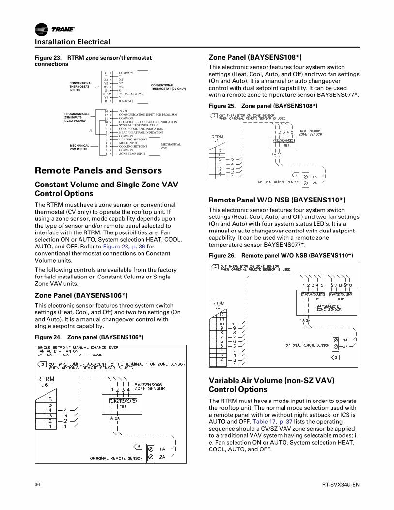
36 RT-SVX34U-EN
Figure 23. RTRM zone sensor/thermostatconnections
PROGRAMMABLE ZSM INPUTS CV/SZ VAV/VAV
CONVENTIONALTHERMOSTAT (CV ONLY)
MECHANICALZSM INPUTS
CONVENTIONALTHERMOSTATINPUTS
Remote Panels and SensorsConstant Volume and Single Zone VAVControl OptionsThe RTRM must have a zone sensor or conventionalthermostat (CV only) to operate the rooftop unit. Ifusing a zone sensor, mode capability depends uponthe type of sensor and/or remote panel selected tointerface with the RTRM. The possibilities are: Fanselection ON or AUTO, System selection HEAT, COOL,AUTO, and OFF. Refer to Figure 23, p. 36 forconventional thermostat connections on ConstantVolume units.
The following controls are available from the factoryfor field installation on Constant Volume or SingleZone VAV units.
Zone Panel (BAYSENS106*)This electronic sensor features three system switchsettings (Heat, Cool, and Off) and two fan settings (Onand Auto). It is a manual changeover control withsingle setpoint capability.
Figure 24. Zone panel (BAYSENS106*)
Zone Panel (BAYSENS108*)This electronic sensor features four system switchsettings (Heat, Cool, Auto, and Off) and two fan settings(On and Auto). It is a manual or auto changeovercontrol with dual setpoint capability. It can be usedwith a remote zone temperature sensor BAYSENS077*.
Figure 25. Zone panel (BAYSENS108*)
Remote Panel W/O NSB (BAYSENS110*)This electronic sensor features four system switchsettings (Heat, Cool, Auto, and Off) and two fan settings(On and Auto) with four system status LED's. It is amanual or auto changeover control with dual setpointcapability. It can be used with a remote zonetemperature sensor BAYSENS077*.
Figure 26. Remote panel W/O NSB (BAYSENS110*)
Variable Air Volume (non-SZ VAV)Control OptionsThe RTRM must have a mode input in order to operatethe rooftop unit. The normal mode selection used witha remote panel with or without night setback, or ICS isAUTO and OFF. Table 17, p. 37 lists the operatingsequence should a CV/SZ VAV zone sensor be appliedto a traditional VAV system having selectable modes; i.e. Fan selection ON or AUTO. System selection HEAT,COOL, AUTO, and OFF.
IInnssttaallllaattiioonn EElleeccttrriiccaall

RT-SVX34U-EN 37
Default Mode Input for Discharge Air ControlFor unit stand-alone operation without a remote panelor an ICS connected, jumper between terminals J6-2and J6-4 on RTRM.
VHR Relay OutputFor stand alone VAV unit operation, the VHR outputshould be wired to drive VAV boxes to maximumposition during all heating modes and unoccupiedperiods. The VHR contacts are shown in the de-energized position and will switch (energize) during theabove mentioned operating modes.
Figure 27. VHR relay output
Heat mode/unoccupied mode relay output to VAVNote:
Table 17. Variable air volume mode operation
SystemMode Fan “Auto” Fan “On”
Heat
DWU Active DWU(a) DWU(a)
DWU Off Off(b) VAV Heating(b)
Cool VAV Cooling(c) VAV Cooling
Auto
DWU ActiveDWU orCooling(c)(a)(b)(d)
DWU orCooling(c)(a)(b)(d)
DWU Off VAV Cooling(c)
VAV Coolingor Heating(c)
Off Off (b) Off (b)
(a) If Daytime Warmup is Activated, the supply fan will run continuously.(b) The fan will be Off any time the system selection switch is “Off”.(c) If Cooling is selected the supply fan will run continuously. If VAV
Heating is activated the supply fan will run continuously.(d) Auto changeover between Cooling and Daytime Warmup depends
upon the DWU initiate setpoint.
VAV Controls Available from the Factoryfor Field Installation
Remote Zone Sensor (BAYSENS016*)This bullet type temperature sensor can be used for;outside air (ambient) sensing, return air temperaturesensing, supply air temperature sensing, remotetemperature sensing (uncovered), and for VAV zonereset. Wiring procedures vary according to theparticular application and equipment involved. Refer to
the unit wiring diagrams, engineering bulletins, and/orany specific instructions for connections.
Remote Panel W/O NSB (BAYSENS021*)This electronic sensor features two system switchsettings (Auto and Off), four system status LED's withsingle setpoint capability. It can be used with a remotezone temperature sensor BAYSENS077*.
Figure 28. Remote panel W/O NSB (BAYSENS021*)CUT RESISTOR R69 LOCATED ON RTAM NEAR SUPPLY AIR COOLING SETPOINT POTENTIOMETER WHEN OPTIONAL REMOTE PANEL IS USED.
CUT WIRE JUMPER ADJACENT T O THE TERMINAL 1 ON ZONE SENSORWHEN OPTIONAL REMOTE SENSOR IS USED.
1
2
*
Constant Volume or VAV (Traditional orSingle Zone) Controls Available from theFactory for Field Installation
Remote Zone Sensor (BAYSENS073*)This electronic sensor features remote zone sensingand timed override with override cancellation. It is usedwith a Trane Integrated Comfort™ buildingmanagement system.
Figure 29. Remote zone sensor (BAYSENS073*)
Remote Zone Sensor (BAYSENS074*)This electronic sensor features single setpointcapability and timed override with overridecancellation. It is used with a Trane IntegratedComfort™ building management system.
IInnssttaallllaattiioonn EElleeccttrriiccaall
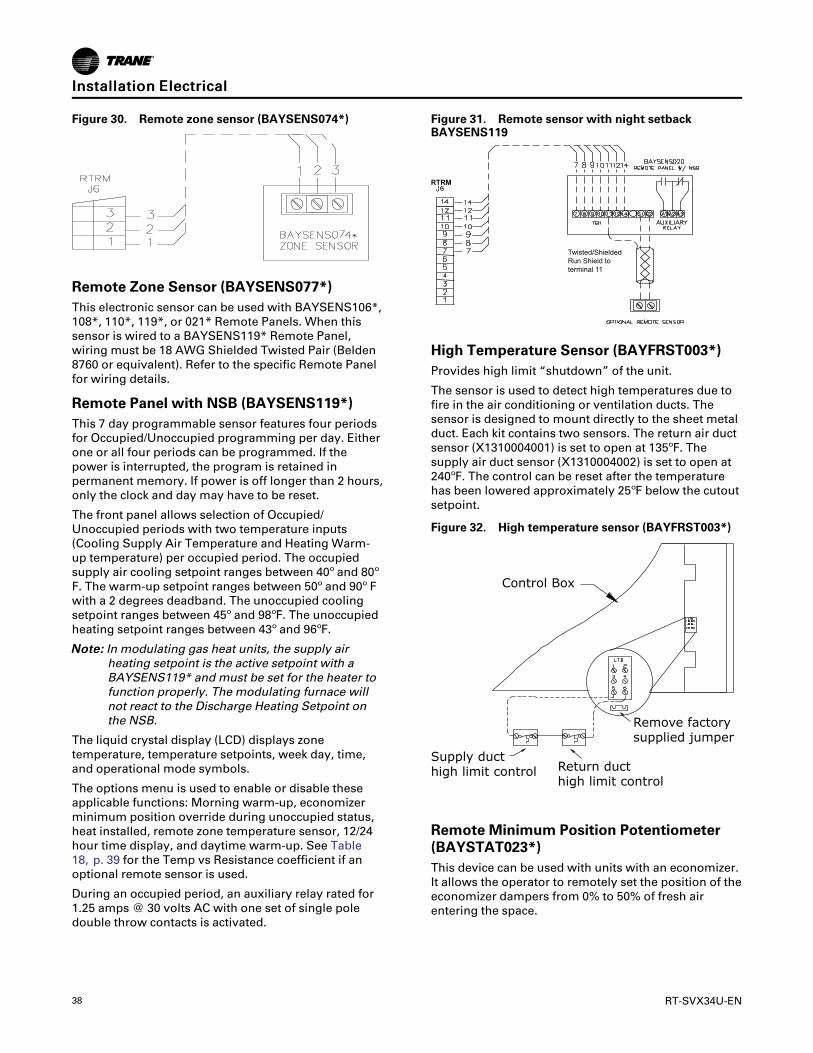
38 RT-SVX34U-EN
Figure 30. Remote zone sensor (BAYSENS074*)
Remote Zone Sensor (BAYSENS077*)This electronic sensor can be used with BAYSENS106*,108*, 110*, 119*, or 021* Remote Panels. When thissensor is wired to a BAYSENS119* Remote Panel,wiring must be 18 AWG Shielded Twisted Pair (Belden8760 or equivalent). Refer to the specific Remote Panelfor wiring details.
Remote Panel with NSB (BAYSENS119*)This 7 day programmable sensor features four periodsfor Occupied/Unoccupied programming per day. Eitherone or all four periods can be programmed. If thepower is interrupted, the program is retained inpermanent memory. If power is off longer than 2 hours,only the clock and day may have to be reset.
The front panel allows selection of Occupied/Unoccupied periods with two temperature inputs(Cooling Supply Air Temperature and Heating Warm-up temperature) per occupied period. The occupiedsupply air cooling setpoint ranges between 40º and 80ºF. The warm-up setpoint ranges between 50º and 90º Fwith a 2 degrees deadband. The unoccupied coolingsetpoint ranges between 45º and 98ºF. The unoccupiedheating setpoint ranges between 43º and 96ºF.
NNoottee:: In modulating gas heat units, the supply airheating setpoint is the active setpoint with aBAYSENS119* and must be set for the heater tofunction properly. The modulating furnace willnot react to the Discharge Heating Setpoint onthe NSB.
The liquid crystal display (LCD) displays zonetemperature, temperature setpoints, week day, time,and operational mode symbols.
The options menu is used to enable or disable theseapplicable functions: Morning warm-up, economizerminimum position override during unoccupied status,heat installed, remote zone temperature sensor, 12/24hour time display, and daytime warm-up. See Table18, p. 39 for the Temp vs Resistance coefficient if anoptional remote sensor is used.
During an occupied period, an auxiliary relay rated for1.25 amps @ 30 volts AC with one set of single poledouble throw contacts is activated.
Figure 31. Remote sensor with night setbackBAYSENS119
Twisted/ShieldedRun Shield to terminal 11
RTRM
High Temperature Sensor (BAYFRST003*)Provides high limit “shutdown” of the unit.
The sensor is used to detect high temperatures due tofire in the air conditioning or ventilation ducts. Thesensor is designed to mount directly to the sheet metalduct. Each kit contains two sensors. The return air ductsensor (X1310004001) is set to open at 135ºF. Thesupply air duct sensor (X1310004002) is set to open at240ºF. The control can be reset after the temperaturehas been lowered approximately 25ºF below the cutoutsetpoint.
Figure 32. High temperature sensor (BAYFRST003*)
Control Box
Remove factorysupplied jumper
Return ducthigh limit control
Supply ducthigh limit control
Remote Minimum Position Potentiometer(BAYSTAT023*)This device can be used with units with an economizer.It allows the operator to remotely set the position of theeconomizer dampers from 0% to 50% of fresh airentering the space.
IInnssttaallllaattiioonn EElleeccttrriiccaall

RT-SVX34U-EN 39
Figure 33. Remote minimum position potentiometer(BAYSTAT023)
Space Temperature AveragingSpace temperature averaging is accomplished bywiring a number of remote sensors in a series/parallelcircuit.
The fewest number of sensors required to accomplishspace temperature averaging is four. Example #1illustrates two series circuits with two sensors in eachcircuit wired in parallel. Any number squared, is thenumber of remote sensors required. Example #2illustrates three sensors squared in a series/parallelcircuit. NSB panel remote sensors must use twisted/shielded cable.
Figure 34. Space temperature averaging
To RTRM J6-1 and J6-2 or to ZSM terminals 1 and 2 or NSB panel terminals S1 and S2. Shield to terminal 11.
Example #1
Example #2
Remote Sensor #1 Remote Sensor #2
Remote Sensor #3 Remote Sensor #4
Remote Sensor #1 Remote Sensor #2 Remote Sensor #3
Remote Sensor #4 Remote Sensor #5 Remote Sensor #6
Remote Sensor #7 Remote Sensor #8 Remote Sensor #9
Table 18. Temperature vs. resistance (temperaturevs. resistance coefficient is negative)
Degrees F° NominalResistance
-20° 170.1 K - Ohms
-15° 143.5 K - Ohms
-10° 121.4 K - Ohms
-5° 103.0 K - Ohms
0° 87.56 K - Ohms
5° 74.65 K - Ohms
10° 63.80 K - Ohms
15° 54.66 K - Ohms
20° 46.94 K - Ohms
25° 40.40 K - Ohms
30° 34.85 K - Ohms
35° 30.18 K - Ohms
40° 26.22 K - Ohms
45° 22.85 K - Ohms
50° 19.96 K - Ohms
55° 17.47 K - Ohms
60° 15.33 K - Ohms
65° 13.49 K - Ohms
70° 11.89 K - Ohms
75° 10.50 K - Ohms
80° 9.297 K - Ohms
85° 8.247 K - Ohms
90° 7.330 K - Ohms
95° 6.528 K - Ohms
100° 5.824 K - Ohms
IInnssttaallllaattiioonn EElleeccttrriiccaall

40 RT-SVX34U-EN
Installation PipingGeneral Requirements
WWAARRNNIINNGGHHaazzaarrddoouuss GGaasseess aanndd FFllaammmmaabblleeVVaappoorrss!!FFaaiilluurree ttoo oobbsseerrvvee tthhee ffoolllloowwiinngg iinnssttrruuccttiioonnss ccoouullddrreessuulltt iinn eexxppoossuurree ttoo hhaazzaarrddoouuss ggaasseess,, ffuueellssuubbssttaanncceess,, oorr ssuubbssttaanncceess ffrroomm iinnccoommpplleetteeccoommbbuussttiioonn,, wwhhiicchh ccoouulldd rreessuulltt iinn ddeeaatthh oorr sseerriioouussiinnjjuurryy.. TThhee ssttaattee ooff CCaalliiffoorrnniiaa hhaass ddeetteerrmmiinneedd tthhaatttthheessee ssuubbssttaanncceess mmaayy ccaauussee ccaanncceerr,, bbiirrtthh ddeeffeeccttss,,oorr ootthheerr rreepprroodduuccttiivvee hhaarrmm..IImmpprrooppeerr iinnssttaallllaattiioonn,, aaddjjuussttmmeenntt,, aalltteerraattiioonn,,sseerrvviiccee oorr uussee ooff tthhiiss pprroodduucctt ccoouulldd ccaauusseeffllaammmmaabbllee mmiixxttuurreess oorr lleeaadd ttoo eexxcceessssiivvee ccaarrbboonnmmoonnooxxiiddee.. TToo aavvooiidd hhaazzaarrddoouuss ggaasseess aannddffllaammmmaabbllee vvaappoorrss ffoollllooww pprrooppeerr iinnssttaallllaattiioonn aannddsseettuupp ooff tthhiiss pprroodduucctt aanndd aallll wwaarrnniinnggss aass pprroovviiddeeddiinn tthhiiss mmaannuuaall..
All internal gas piping for YC* rooftop units are factoryinstalled and leak tested. Once the unit is set into place,a gas supply line must be field installed and connectedto the gas train located inside the gas heatcompartment.
Access holes are provided on the unit as shown inFigure 12, p. 19 to accommodate side panel entry.Following the guidelines listed below will enhance boththe installation and operation of the furnace.
NNoottee:: In the absence of local codes, the installationmust conform with the American NationalStandard Z223.1a of the National Fuel Gas Code,(latest edition).
1. To assure sufficient gas pressure at the unit, use todetermine the appropriate gas pipe size for theheating capacity listed on the unit's nameplate.
If a gas line already exists, verify that it is sizedlarge enough () to handle the additional furnacecapacity.
2. Take all branch piping from any main gas line fromthe top at 90 degrees or side at 45 degrees toprevent moisture from being drawn in with the gas.
3. Ensure that all piping connections are adequatelycoated with joint sealant and properly tightened.Use a piping compound that is resistant to liquidpetroleum gases.
4. Provide a drip leg near the unit.
NNOOTTIICCEEGGaass VVaallvvee DDaammaaggee!!FFaaiilluurree ttoo ffoollllooww iinnssttrruuccttiioonnss bbeellooww ccoouulldd rreessuulltt iinnggaass vvaallvvee ddaammaaggee ffrroomm iinnccoorrrreecctt ggaass pprreessssuurreess,,iirrrreegguullaarr ppuullssaattiinngg ffllaammee ppaatttteerrnnss,, bbuurrnneerr rruummbbllee,,aanndd ppootteennttiiaall ffllaammee oouuttaaggeess..UUssee aa pprreessssuurree rreegguullaattoorr ttoo pprrooppeerrllyy rreegguullaattee ggaasspprreessssuurree.. DDOO NNOOTT oovveerrssiizzee tthhee rreegguullaattoorr..
5. Install a pressure regulator at the unit that isadequate to maintain 6" w.c. for natural gas and 11"w.c. for LP gas while the unit is operating in the“High Heat” mode. A minimum inlet gas pressureof 2.5" w.c. for natural gas and 8" w.c. for LP gas isrequired while operating in the “High Heat” mode.
NNoottee:: Gas pressure in excess of 14" w.c. or 0.5 psigwill damage the gas train.
WWAARRNNIINNGGEExxpplloossiioonn HHaazzaarrdd!!FFaaiilluurree ttoo ffoollllooww ssaaffee lleeaakk tteesstt pprroocceedduurreess bbeelloowwccoouulldd rreessuulltt iinn ddeeaatthh oorr sseerriioouuss iinnjjuurryy oorreeqquuiippmmeenntt oorr pprrooppeerrttyy--oonnllyy--ddaammaaggee..NNeevveerr uussee aann ooppeenn ffllaammee ttoo ddeetteecctt ggaass lleeaakkss.. UUssee aalleeaakk tteesstt ssoolluuttiioonn ffoorr lleeaakk tteessttiinngg..
6. Leak test the gas supply line using a soap-and-water solution or equivalent before connecting it tothe gas train.
7. Pressure test the supply line before connecting it tothe unit to prevent possible gas valve damage andthe unsafe operating conditions that will result.
NNoottee:: Do not rely on gas train shutoff valves toisolate the unit while conducting gaspressure/leak test. These valves are notdesigned to withstand pressures in excess of14" w.c. or 0.5 psig.
Connecting the Gas Supply Lineto the Furnace Gas TrainFollow the steps below to complete the installationbetween the supply gas line and the furnace. Refer toFigure 35, p. 41 for the Gas Train configuration.
1. Connect the supply gas piping using a “ground-joint” type union to the furnace gas train and checkfor leaks.
2. Provide adequate support for the field installed gaspiping to avoid stressing the gas train and controls.
3. Adjust the inlet supply gas pressure to therecommended 6" for natural gas or 11" w.c. for LPgas.
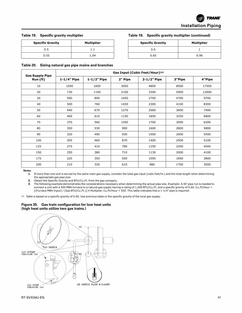
RT-SVX34U-EN 41
Table 19. Specific gravity multiplier
Specific Gravity Multiplier
0.5 1.1
0.55 1.04
Table 19. Specific gravity multiplier (continued)
Specific Gravity Multiplier
0.6 1
0.65 0.96
Table 20. Sizing natural gas pipe mains and branches
Gas Supply PipeRun (ft)
Gas Input (Cubic Feet/Hour)(a)
1-1/4” Pipe 1-1/2” Pipe 2" Pipe 2-1/2” Pipe 3"Pipe 4"Pipe
10 1050 1600 3050 4800 8500 17500
20 730 1100 2100 3300 5900 12000
30 590 890 1650 2700 4700 9700
40 500 760 1450 2300 4100 8300
50 440 670 1270 2000 3600 7400
60 400 610 1150 1850 3250 6800
70 370 560 1050 1700 3000 6200
80 350 530 990 1600 2800 5800
90 320 490 930 1500 2600 5400
100 305 460 870 1400 2500 5100
125 275 410 780 1250 2200 4500
150 250 380 710 1130 2000 4100
175 225 350 650 1050 1850 3800
200 210 320 610 980 1700 3500
Notes:1. If more than one unit is served by the same main gas supply, consider the total gas input (cubic feet/hr.) and the total length when determining
the appropriate gas pipe size.2. Obtain the Specific Gravity and BTU/Cu.Ft. from the gas company.3. The following example demonstrates the considerations necessary when determining the actual pipe size. Example: A 40' pipe run is needed to
connect a unit with a 500 MBH furnace to a natural gas supply having a rating of 1,000 BTU/Cu.Ft. and a specific gravity of 0.60. Cu.Ft/Hour =[(Furnace MBH Input) / (Gas BTU/Cu.Ft.)] X Multiplier. Cu.Ft/Hour = 500. This table indicates that a 1-1/4” pipe is required.
(a) Table is based on a specific gravity of 0.60. Use previous table or the specific gravity of the local gas supply.
Figure 35. Gas train configuration for low heat units(high heat units utilize two gas trains.)
IInnssttaallllaattiioonn PPiippiinngg

42 RT-SVX34U-EN
StartupUnit Control ModulesRTRM - ReliaTel™™ Refrigeration ModuleThe RTRM is the main information receiving module. Itinterprets the information received from all other unitmodules, sensors, remote panels, customer binarycontacts and responds by activating the various unitcomponents to satisfy the applicable request foreconomizing, cooling, heating, exhaust, ventilation.The RTRM configuration is set through the wireharness to function within one of six systemapplications:
• Constant Volume Supply Air with No Heat.
• Constant Volume Supply Air with Gas or ElectricHeat.
• Variable Supply Air Volume with No Heat.
• Variable Supply Air Volume with Gas or ElectricHeat.
• Single Zone Variable Supply Air Volume with NoHeat.
• Single Zone Variable Supply Air Volume with Gasor Electric Heat.
ECA/RTEM - Economizer Actuator/ReliaTel Economizer Module (Optional)The ECA/RTEM monitors the mixed air temperature,return air temperature, minimum position setpoint(local or remote), ambient dry bulb/enthalpy sensor orcomparative humidity (return air humidity againstambient humidity) sensors, if selected, to control thedampers to an accuracy of +/- 5% of the stroke. Theactuator is spring returned (FA closed, RA opened) anytime power is lost to the unit. Refer to “MechanicalCooling with an Economizer ,” p. 59 for the properpotentiometer settings for dry bulb/Enthalpy control.
NNoottee:: The ECA/RTEM control module is mounted onthe actuator. Units with the ultra-low-leakeconomizer option have their ECA controlmodule mounted to a panel adjacent to the RAdamper.
EBA - Exhaust Blade Actuator (Optional)If the unit is ordered with tracking power exhaust, theEBA will track the economizer damper position as longas the active exhaust fan setpoint has been exceeded -set via RTOM, through BAS, or calculated (SZ VAVonly). The actuator limits the maximum travel of theexhaust barometric damper. The exhaust bladeactuator is spring returned and is closed any timepower is lost to the unit.
RTAM - ReliaTel Air Handler Module(Standard with Traditional VAV)The RTAM receives information from the supply ductstatic pressure transducer. Attached to the module arethe supply air heating potentiometer, supply air coolingsetpoint potentiometer, supply pressure setpointpotentiometer, static pressure deadbandpotentiometer, morning warm-up setpointpotentiometer, reset setpoint potentiometer, and 5 DIPswitches. See following figure.
Figure 36. RTAMmodule
DIP Switches:
• Switch 1 is “ON” for VFD's.
• Switch 2 is “OFF” for VAV.
• Switch 3 and 4 operation are explained under“supply air temperature reset”.
• Switch 5 is “OFF” for DWU Disabled and “ON” forDWU Enabled.
The RTAM module provides a 0 to 10 Vdc output tocontrol the Variable Frequency Drive. DIP switcheslocated on the RTAM configures the unit to use theoutput for a VFD. Customer changeover input fromLow Voltage Terminal Board (LTB5) activates VAVheating. The Supply Air Heating setpoint must be set tothe desired discharge air temperature for heating. ThisVAV heating mode is available only with modulatinggas heat units. In this mode the gas heaters modulate
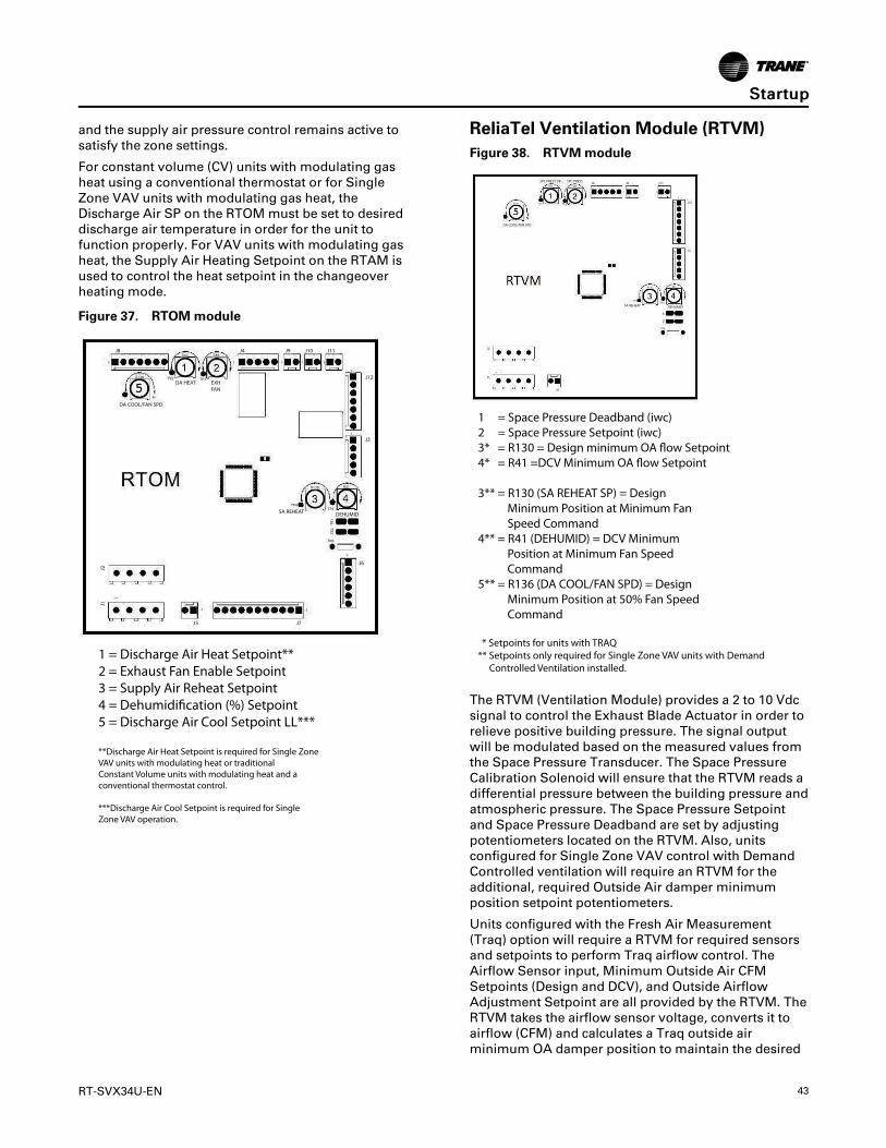
RT-SVX34U-EN 43
and the supply air pressure control remains active tosatisfy the zone settings.
For constant volume (CV) units with modulating gasheat using a conventional thermostat or for SingleZone VAV units with modulating gas heat, theDischarge Air SP on the RTOM must be set to desireddischarge air temperature in order for the unit tofunction properly. For VAV units with modulating gasheat, the Supply Air Heating Setpoint on the RTAM isused to control the heat setpoint in the changeoverheating mode.
Figure 37. RTOMmodule
J8 J4 J9 J10 J11
J12
J3
J6
J7J5
J1J2
DA COOL/FAN SPD
DA HEAT EXHFAN
SA REHEAT DEHUMID
1- 1 1 11-
1-
1-
1-
TP4TP5
R41R130
R46
-1-1
-1
TB2
TB1
R136 TP2 TP3
R42 R40
1 = Discharge Air Heat Setpoint**2 = Exhaust Fan Enable Setpoint3 = Supply Air Reheat Setpoint4 = Dehumidi!cation (%) Setpoint5 = Discharge Air Cool Setpoint LL***
**Discharge Air Heat Setpoint is required for Single Zone VAV units with modulating heat or traditional Constant Volume units with modulating heat and a conventional thermostat control.
***Discharge Air Cool Setpoint is required for Single Zone VAV operation.
ReliaTel Ventilation Module (RTVM)Figure 38. RTVMmodule
DA COOL/FAN SPD
SA REHEAT DEHUMID
SPC PRESS DB SPC PRESS
R136
J4 J9 J11
J12
J3
J1J2
TP2 TP3
R42 R40
1- 1 1
1-
TP4TP5
R130 R41
TB2
TB1
R46
-1
-1
J5
1-
1 = Space Pressure Deadband (iwc)2 = Space Pressure Setpoint (iwc)3* = R130 = Design minimum OA !ow Setpoint4* = R41 =DCV Minimum OA !ow Setpoint
3** = R130 (SA REHEAT SP) = Design Minimum Position at Minimum Fan Speed Command4** = R41 (DEHUMID) = DCV Minimum Position at Minimum Fan Speed Command5** = R136 (DA COOL/FAN SPD) = Design Minimum Position at 50% Fan Speed Command
* Setpoints for units with TRAQ** Setpoints only required for Single Zone VAV units with Demand Controlled Ventilation installed.
The RTVM (Ventilation Module) provides a 2 to 10 Vdcsignal to control the Exhaust Blade Actuator in order torelieve positive building pressure. The signal outputwill be modulated based on the measured values fromthe Space Pressure Transducer. The Space PressureCalibration Solenoid will ensure that the RTVM reads adifferential pressure between the building pressure andatmospheric pressure. The Space Pressure Setpointand Space Pressure Deadband are set by adjustingpotentiometers located on the RTVM. Also, unitsconfigured for Single Zone VAV control with DemandControlled ventilation will require an RTVM for theadditional, required Outside Air damper minimumposition setpoint potentiometers.
Units configured with the Fresh Air Measurement(Traq) option will require a RTVM for required sensorsand setpoints to perform Traq airflow control. TheAirflow Sensor input, Minimum Outside Air CFMSetpoints (Design and DCV), and Outside AirflowAdjustment Setpoint are all provided by the RTVM. TheRTVM takes the airflow sensor voltage, converts it toairflow (CFM) and calculates a Traq outside airminimum OA damper position to maintain the desired
SSttaarrttuupp

44 RT-SVX34U-EN
adjustable CFM setpoint value. The airflow can beadjusted for altitude differences with the OutsideAirflow Adjustment Setpoint.
ReliaTel Dehumidification Module(RTDM)Figure 39. RTDMmodule
The RTDM provides a pulsed signal output to controlthe Cooling and Reheat Modulating Valves. The RTDMwill also monitor the Entering Evaporator Temperatureas well as protect against a low refrigerant pressure inthe reheat circuit.
Conventional Thermostat Connections(Available Only with CV)This feature allows conventional thermostats to beused in conjunction with the RTRM on ConstantVolume Applications only. It utilizes the conventionalwiring scheme of R, Y1, Y2, W1, W2/X, and G. Refer toFigure 23, p. 36 for conventional thermostatconnections. Applicable thermostats to be used withthe conventional thermostat inputs are:
Table 21. Thermostats
Vendor Part # Trane Part #
Honeywell T7300
Honeywell T874D1082 BAYSTAT011
Enerstat MS-1N BAYSTAT003
TCI - Trane Communication Interface(Optional)This module is used when the application calls for anICS building management type control system. Itallows the control and monitoring of the systemthrough a Trane Tracer® panel. The module can beordered from the factory or ordered as a kit to be fieldinstalled. Follow the installation instructions that shipwith each kit when field installation is necessary.
LCI - LonTalk®® Communication Interface(Optional)This module is used when the application calls for aLonTalk building management type control system. It
allows the control and monitoring of the systemthrough a Trane Tracer Summit panel or 3rd partyLonTalk system. The module can be ordered from thefactory or ordered as a kit to be field installed. Followthe installation instructions that ship with each kitwhen field installation is necessary.
BCI - BACnet®® Communication Interface(Optional)This module is used when the application calls for aBACnet building management type control system. Itallows the control and monitoring of the systemthrough a Trane Tracer SC panel or 3rd party BACnetsystem. The module can be ordered from the factory orordered as a kit to be field installed. Follow theinstallations instructions that ship with each kit whenfield installation is necessary.
WCI - Trane Air-Fi®®Wireless CommInterface (Optional)The Trane® Air-Fi Wireless Comm Interface (WCI) is theperfect alternative to Trane’s BACnet® wiredcommunication links (for example, Comm linksbetween a Tracer® SC and a Tracer UC400). Minimizingcommunication wire used between terminal products,zone sensors, and system controllers has substantialbenefits. Installation time and associated risks arereduced. Projects are completed with fewerdisruptions. Future re-configurations, expansions, andupgrades are easier and more cost effective.
TD5 Display - 5" Touchscreen DisplayThe Tracer TD5 display is an optional display modulethat operates in conjunction with the ReliaTelController and allows you to view data and makeoperational changes. More information on the TracerTD5 Display can be found in Installation, Operation,and Maintenance Manual, RT-SVX49*-EN.
System OperationEconomizer Operation with aConventional Thermostat (CV Only)If the ambient conditions are suitable for economizeroperation, the economizer is activated as the 1st step ofcooling from Y1. The dampers are controlled to providea supply air temperature of 50° F +/- 5° F. If theeconomizer is disabled due to ambient conditions, the1st stage of mechanical cooling is activated.
While economizing, if an additional stage of cooling isactivated from Y2, the 1st stage of mechanical coolingis activated. If the economizer is disabled due toambient conditions, the 2nd stage of mechanicalcooling is activated.
The supply fan is activated from the G terminal and willcycle with a call for heat or cooling if in the “Auto”
SSttaarrttuupp
RT-SVX34U-EN 45
mode. It will run continuously in the “On” moderegardless of any other system demand.
On gas heat units, first and second stages are activatedby the W1 and W2 terminals on the CTI. On electricheat units, only two stages of heat are available. If theW2 terminal is activated without activating the W1terminal, the RTRM will bring on both stages of electricheat.
The conventional thermostat connections can also beutilized as a generic building automation systeminterface for constant volume ICS applications. Due tothe limited heating and cooling steps when using aconventional thermostat, compressor staging will varyon units with three compressors.
NNoottee:: If a conventional thermostat is used with a unitthat has modulating gas heat, the unit willcontrol to the Discharge Air SP potentiometer onthe RTOM when heating with a W1 call only. Theunit will go to high fire with W1 + W2.
Microelectronic Control Features
Anti Short Cycle Timer (ASCT)Compressor operation is programmed for 3 minutes ofminimum “ON” time, and 3 minutes of minimum“OFF” time. Enhances compressor reliability, andensures proper oil return.
NNoottee:: Compressor cycle rate minimization, extendscompressor life expectancy, minimizesdamaging compressor inrush current, andguards against short cycling.
Delay Between Stages TimerWhen combined with a standard Zone Sensor Module,the Reliatel Refrigeration Module (RTRM) provides a 10second minimum “ON” delay for compressor staging.
Built-in Fan Delay Relay (Constant Volumeand Single Zone VAV Units)When the fan mode switch on the Zone Sensor Moduleis set in the auto position, the RTRM providesindividual supply fan timing sequences for each systemin heating and cooling. The RTRM provides differenttiming sequences for Gas Heat units and Cooling onlyunits.
Low Ambient CoolingLow ambient cooling to 0°F with Frostat™.
Built-in Electric Heat StagingProvides a 10 second “ON” delay between resistanceheat stages.
Economizer Preferred CoolingAllows fully integrated economizer operation withmechanical cooling if actually needed.
On Constant Volume and Single Zone VAVapplications, a 3 minute delay allows the RTRM to
evaluate the rate of change in the zone. If the zonetemperature is dropping faster than acceptableparameters, the compressor(s) will not be required tooperate.
Free Night SetbackAllows the unit to enter an unoccupied mode by simplyshorting across terminals RTRM J6-11 and J6-12. Theshort can be achieved by a set of dry contacts or a timeclock. Once this short has been made the unit will closethe economizer dampers, go from continuous fan toauto fan operation.
ON CV or SZ VAV units with mechanical ZSM:
• If the unit has a valid cooling and heating setpoint,the setup/setback is a minimum of 7°F.
• If the unit does not have both setpoints, the setup/setback is 0°.
• If the unit has neither setpoint, the unoccupiedcooling/heating setpoints will be 74°F/71°F.
• If the unit is configured as a Constant Volume unitand a conventional thermostat is used, this input isignored and the unit will respond to thermostatrequests as during normal occupied mode.
• VAV unit w/o ICS or NSB energizes heating if thespace temperature drops to 10°F below the MWUsetpoint but not less than 50°F.
• This option can not be used with programmableZSM or with an ICSTM system.
Low Pressure CutoutsLow pressure cutouts on all compressors have beenadded to insure compressor reliability in lowrefrigerant flow situations. The compressor(s) willlockout after four consecutive low pressure controltrips during the compressor minimum 3 minute “on”time. The lockout will have to be manual reset asexplained in this document.
Economizer Operation with CV ControlsThe control point for the economizer is designed tocontrol at least 1.5°F below the cooling setpoint or 1.5°F above the heating setpoint, whichever produces thehighest economizer control setpoint.
Example:
Heating Setpoint = 68°F
Cooling Setpoint = 70°F
The control temperature for the economizer will be 1.5°F above the heating setpoint due to it producing theleast amount of offset.
Heating Setpoint = 55°F
Cooling Setpoint = 75°F
Because of the spread between the heating and coolingsetpoints, the control will choose to control theeconomizer at an offset temperature of 1.5°F below the
SSttaarrttuupp

46 RT-SVX34U-EN
cooling setpoint. This will be the highest resultingcontrol setpoint temperature while maintaining theleast amount of offset.
The percentage that the economizer dampers open isbased on two factors:
• The zone temperature minus the economizersetpoint, and,
• The zone temperature minus the outdoor airtemperature.
NNoottee:: The following table lists the percentages thedampers will open based on these conditions.
Table 22. Percent of damper travel
Zone -ODT
Zone Temp - Econ Setpoint °F
0.0-0.5
0.5-1.0
1.0-2.0
2.0-3.0
3.0-5.0 >5.0
0 - 7°F 0% 3% 9% 30% 90% 100%
7 - 14°F 0% 2% 6% 20% 60% 100%
> 14°F 0% 1% 3% 10% 30% 100%
While economizing, if the supply air temperature fallsbelow 50°F, the damper will not be allowed to open anyfurther until the supply air temperature rises above 50°F. If the supply air temperature falls below 45°F, thedampers will be driven to minimum position and heldthere until the supply air temperature rises above 50°F.
The mechanical cooling is disabled while in aneconomizing state until two conditions are met:
• The economizer dampers have been fully open forthree minutes, and;
• The calculated rate of change in the zonetemperature is less than 12°F per hour.
If the economizer is disabled due to unsuitableconditions, the economizer is at the selected minimumposition when the supply fan is ““OOnn””, and is closedwhen the supply fan is ““OOffff””. The mechanical coolingwill cycle as though the unit had no economizer.
Modulating Power ExhaustIf the unit is equipped with the modulating powerexhaust option, the power exhaust actuator will followthe position of the economizer actuator.
Mechanical Cooling without anEconomizer (CV and SZ VAV)Mechanical cooling is used to maintain the zonetemperature. The RTRM is designed to limit thecompressor cycle rates to within 10 cycles per hourbased on the minimum compressor “on” and “off”times.
It stages the mechanical cooling to control the zonetemperature to within +/- 2°F of the sensor setpoint atthe sensed location. Table 23, p. 46 lists thecompressor staging sequence for standard efficiencyunits.
For high efficiency units there are three separatestaging sequences which determine the staging of 3compressors within each sequence. Each call for coolwill operate within a given sequence and the next callfor cool will operate in the next sequence. Lead/Lagoperation is taken into consideration with these 3staging sequences and will be active when Lead/Lag isconfigured. Table 24, p. 47 lists the compressor stagingsequence for high efficiency units.
Table 23. Compressor staging with lead/lag disabled- std efficiency units (excluding 40–50T CVunits)
UnitModel
“ON” “OFF”
Step1
Step2
Step3
Step3
Step2
Step1
27.5 - 35 CPR 1(a)
CPR1, 2 N/A N/A CPR
1, 2 CPR 1
40 CPR 1(b)
CPR 2(c)
CPR1, 2
CPR1, 2
CPR 2(c)
CPR 1(b)
50 CPR 1(b)
CPR2,3(d)
CPR1, 2,3
CPR1, 2,3
CPR2, 3(d)
CPR 1(b)
(a) Single circuit, dual manifolded compressors(b) Number one refrigeration circuit, Standalone compressor, is “On”.(c) First stage is off. Number two refrigeration circuit, standalone
compressor, is “On”(d) First Stage is “Off”, Number two refrigeration circuit, manifolded
compressor pair operating simultaneously, is “On”.
SSttaarrttuupp

RT-SVX34U-EN 47
Table 24. Compressor staging sequence - highefficiency units and std eff. 40–50T CV units)
Sequence 1 Sequence 2
Sta-ge
CPR1
CPR2
CPR3
Sta-ge
CPR1
CPR2
CPR3
1 ON OFF OFF 1 Start at Stage 2
2 OFF ON OFF 2 OFF ON OFF
3 ON ON OFF 3 ON ON OFF
4 OFF ON ON 4 OFF ON ON
5 ON ON ON 5 ON ON ON
Sequence 3
Sta-ge
CPR1
CP-R2
CP-R3
1 Start at Stage 2
2 OFF OFF ON
3 ON OFF ON
4 OFF ON ON
5 ON ON ON
Figure 40. Compressors
40 Tons Std Eff. VAV Only27.5, 30, 35 Tons Std Eff.
50 Tons Std Eff. VAV Only 27.5-50 Tons High Eff. & 40-50 TonsStd Eff. CV
Zone Temperature - Occupied Cooling(CV and SZVAV)When the unit is in the cooling mode and the zonetemperature raises above the cooling setpoint controlband, the economizer and the compressor stages willbe cycled as required by the zone sensor, remote panel,or Tracer®. For SZ VAV control, the fan capacity willalso be controlled in order to meet the zone coolingdemand.
Zone Temperature - Occupied Heating(CV and SZVAV)When the unit is in the heating mode and the zonetemperature falls below the heating setpoint controlband, the necessary stages of heat will cycle to raisethe temperature to within the setpoint control band.
For SZ VAV, the fan capacity will also be controlled inorder to meet the zone heating demand.
Supply Fan (CV and SZ VAV)When the Fan Selection Switch is in the “AUTO”position and a call for cooling is initiated, the supplyfan will delay starting for approximately one second ontraditional CV units. For SZ VAV units, the supply fanwill be controlled ON based on the zone coolingdemand. Once ON, the unit will begin staging coolingcapacity (economizer and/or compressors) in order tomeet the discharge air requirements. Once the zonehas been satisfied, the supply fan will be controlledOFF. When the Fan Selection Switch is in the “ON”position, the supply fan will run continuously. If airflowthrough the unit is not proven by the differentialpressure switch (factory setpoint 0.15“w.c.) within 40seconds nominally, the RTRM will shut off allmechanical operations, lock the system out, send adiagnostic to ICS, and the SERVICE LED output willpulse. The system will remain locked out until a reset isinitiated either manually or through ICS or a modetransition from OFF to a non-OFF mode.
Supply Air Tempering (CV and SZ VAV)
CV Units with Staged HeatThis function allows the supply air temperature to bemaintained within a low limit parameter duringminimum ventilation periods. For CV units configuredwith a Staged Heat design (Electric or Gas) and SupplyAir Tempering operation enabled, if the following itemsare true, the unit will enter Supply Air Temperingmode:
• The supply fan is ON.
• The unit is in Occupied mode.
• Zone Temp. is less than the active Cooling setpoint.
• The unit is in Heat mode but is not actively heatingOR
• The unit is in AUTO-COOL mode but not activelycooling and cooling capacity has been OFF for 5minutes.
Once the above conditions are met, if the supply airtemperature drops to 10°F BELOW the OccupiedHeating Zone Temperature Setpoint, the SA Temperingfunction will bring ON one stage of gas or electric heat.
Once SA Tempering is active, heating will be turnedOFF if the Supply Air Temperature rises to 10°F ABOVEthe Active Occupied Zone Heating Setpoint, or theZone Temperature rises to the Active Zone CoolingSetpoint. Also, if the Zone Heat Control function iscalling for 1 or more stages of Heat, Tempering will bediscontinued and the unit will stage additional heatingto meet the current demand.
When an economizer is installed, air tempering isallowed with ICSTM when the fan system switch is inthe “ON” position with no call for heating. The same
SSttaarrttuupp

48 RT-SVX34U-EN
conditions must be met as described above forentering and leaving Tempering operation.
CV Units with Modulating HeatOn units with Modulating Gas Heat, Supply AirTempering is inherent to the Modulating Heat designand does not require any additional configuration/enabling. Modulating Heat Tempering is accomplishedby allowing the unit to return to heating if the Zone ismarginally satisfied and the Supply Air temperaturebegins to fall. The following conditions must be true toenable the unit to perform “Tempering”:
• The supply fan is ON.
• The unit is in Occupied mode.
• Zone Temp. is less than the active Cooling setpoint.
• The unit is in Heat mode but is not actively heatingOR
• The unit is in AUTO-COOL mode but not activelycooling and cooling capacity has been OFF for 5minutes.
Once the above conditions are met, and the supply airtemperature drops below the ZHSP - 10°F, the unit willtransition back into active heating operation and willbegin to control the modulating heat output tomaintain the supply air temperature.
Once the unit has entered into Tempering mode, theunit will leave active heating either by normal heattermination as determined by the heating controlalgorithm or when the Zone Temperature reaches theactive ZCSP.
SZ VAV Units with Staged HeatFor SZ VAV units configured with a Staged Heatingtype, the Supply Air Tempering function will operate ason a CV unit with Staged Heat.
SZ VAV Units with Modulating HeatFor units configured with a Modulating Heat type,“Tempering” is an extension of normal Heating controlwhich allows a transition from inactive “Auto-Cool”mode to Heating based on supply air temperature if theZone Temperature is in control. The followingconditions must be true to allow the unit to enterSupply Air Tempering:
• Supply Fan is ON.
• The unit is in Occupied mode.
• The unit is operating in Auto-Cool Mode.
• Cooling has been inactive for 5 minutes.
When the above conditions are true, Tempering will beallowed when the Supply Air Temperature falls belowthe user selectable Minimum Supply Air CoolingSetpoint (minus deadband) as long as the ZoneTemperature is < ZCSP - 1°F. Once the unit transitionsinto “Tempering” the unit will transition to normalheating control and will control the supply air
temperature between the minimum and maximumsupply air setpoints.
If the Zone Temperature rises above the ZCSP during“Tempering” the unit will de-energize Heating and“Tempering” will be disabled until conditions allow forit again. Normal Auto-Changeover requirements will bein control to allow the unit to transition into Active Coolmode.
Variable Air VolumeApplications (SZ VAV)Supply Fan Output ControlUnits configured for Single Zone VAV will include aVFD controlled supply fan motor which will becontrolled via the 0-10Vdc Indoor Fan Speed outputlocated on the RTOM and the RTRM Supply Fan output.With the RTRM Supply Fan output energized and theRTOM Indoor Fan Speed output at 0Vdc the fan speedoutput is 33% (20Hz) for cooling mode and 58% (35Hz)for heating modes from the VFD motor and at 10Vdcthe fan speed output is 100% (60Hz). The control willscale the 0-10Vdc output from the RTOM linearly tocontrol to 38%-100% controllable range based on thespace heating or cooling demand.
Minimum Supply Fan OutputRefer to the table below for details on minimum supplyfan output signals associated with each unit function.Note that each value represents the actual Fan Output%.
Table 25. Fan output - standard efficiency
Function Minimum Fan Output%
Ventilation Only 58%
Economizer Cooling 58%
Cool 1 (C1 Energized) 58%
Cool 2 (C1 or C2) 67%
Cool 3 (C1 + C2 Energized) 67%
SZVAV Modulating Heat 58%
CV Staged Heat 100%
SZVAV Modulating HeatTempering 58%
CV Staged Heat Tempering 100%
Modulating Reheat 80%
Table 26. Fan output - high efficiency
Function Minimum Fan Output%
Ventilation Only 45%
Economizer Cooling 45%
SSttaarrttuupp
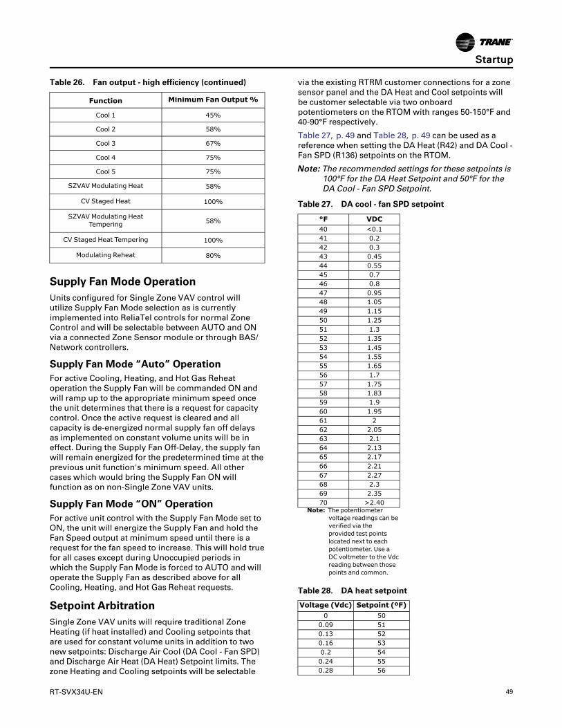
RT-SVX34U-EN 49
Table 26. Fan output - high efficiency (continued)
Function Minimum Fan Output%
Cool 1 45%
Cool 2 58%
Cool 3 67%
Cool 4 75%
Cool 5 75%
SZVAV Modulating Heat 58%
CV Staged Heat 100%
SZVAV Modulating HeatTempering 58%
CV Staged Heat Tempering 100%
Modulating Reheat 80%
Supply Fan Mode OperationUnits configured for Single Zone VAV control willutilize Supply Fan Mode selection as is currentlyimplemented into ReliaTel controls for normal ZoneControl and will be selectable between AUTO and ONvia a connected Zone Sensor module or through BAS/Network controllers.
Supply Fan Mode “Auto” OperationFor active Cooling, Heating, and Hot Gas Reheatoperation the Supply Fan will be commanded ON andwill ramp up to the appropriate minimum speed oncethe unit determines that there is a request for capacitycontrol. Once the active request is cleared and allcapacity is de-energized normal supply fan off delaysas implemented on constant volume units will be ineffect. During the Supply Fan Off-Delay, the supply fanwill remain energized for the predetermined time at theprevious unit function's minimum speed. All othercases which would bring the Supply Fan ON willfunction as on non-Single Zone VAV units.
Supply Fan Mode “ON” OperationFor active unit control with the Supply Fan Mode set toON, the unit will energize the Supply Fan and hold theFan Speed output at minimum speed until there is arequest for the fan speed to increase. This will hold truefor all cases except during Unoccupied periods inwhich the Supply Fan Mode is forced to AUTO and willoperate the Supply Fan as described above for allCooling, Heating, and Hot Gas Reheat requests.
Setpoint ArbitrationSingle Zone VAV units will require traditional ZoneHeating (if heat installed) and Cooling setpoints thatare used for constant volume units in addition to twonew setpoints: Discharge Air Cool (DA Cool - Fan SPD)and Discharge Air Heat (DA Heat) Setpoint limits. Thezone Heating and Cooling setpoints will be selectable
via the existing RTRM customer connections for a zonesensor panel and the DA Heat and Cool setpoints willbe customer selectable via two onboardpotentiometers on the RTOM with ranges 50-150°F and40-90°F respectively.
Table 27, p. 49 and Table 28, p. 49 can be used as areference when setting the DA Heat (R42) and DA Cool -Fan SPD (R136) setpoints on the RTOM.
NNoottee:: The recommended settings for these setpoints is100°F for the DA Heat Setpoint and 50°F for theDA Cool - Fan SPD Setpoint.
Table 27. DA cool - fan SPD setpoint
°F VDC40 <0.141 0.242 0.343 0.4544 0.5545 0.746 0.847 0.9548 1.0549 1.1550 1.2551 1.352 1.3553 1.4554 1.5555 1.6556 1.757 1.7558 1.8359 1.960 1.9561 262 2.0563 2.164 2.1365 2.1766 2.2167 2.2768 2.369 2.3570 >2.40
Note: The potentiometervoltage readings can beverified via theprovided test pointslocated next to eachpotentiometer. Use aDC voltmeter to the Vdcreading between thosepoints and common.
Table 28. DA heat setpoint
Voltage (Vdc) Setpoint (ºF)0 50
0.09 510.13 520.16 530.2 540.24 550.28 56
SSttaarrttuupp

50 RT-SVX34U-EN
Table 28. DA heat setpoint (continued)
Voltage (Vdc) Setpoint (ºF)0.31 570.35 580.42 600.46 610.5 620.53 630.57 640.61 650.65 660.68 670.72 680.76 690.79 700.83 710.87 720.9 730.94 740.98 751 761.03 771.06 781.08 791.11 801.13 811.16 821.18 831.21 841.23 851.26 861.28 871.31 881.33 891.36 901.38 911.41 921.43 931.46 941.48 951.51 961.53 971.56 981.58 991.61 1001.63 1011.66 1021.69 1031.71 1041.72 1051.74 1061.76 1071.78 1081.79 1091.81 1101.83 1111.84 1121.86 1131.88 1141.89 1151.91 1161.93 1171.95 1181.96 1191.98 120
Table 28. DA heat setpoint (continued)
Voltage (Vdc) Setpoint (ºF)2 121
2.01 1222.03 1232.05 1242.06 1252.08 1262.09 1272.11 1282.12 1292.13 1302.13 1312.14 1322.16 1332.17 1342.19 1352.2 1362.21 1372.23 1382.24 1392.25 1402.26 1412.28 1422.29 1432.3 1442.32 1452.33 1462.34 1472.36 1482.37 1492.4 150
NNoottee:: The above potentiometer voltage readings canbe verified via the provided test points locatednext to each potentiometer. Use a DC voltmeterto the Vdc reading between those points andcommon.
Units Configured with the Outside AirMeasurement (Traq) OptionTo make a minor correction to the Traq airflow (CFM)reading that is calculated internally by the ReliaTelsystem, an adjustment pot is available on the RTVM.This pot can be used to correct for static “local” factorssuch as altitude. Variable factors such as drift,temperature, humidity, and other changingatmospheric conditions are corrected as part of theconversion calculation.
The adjustment will typically be made in Service Testmode in a step where the OA damper is beingcommanded to the Traq OA Minimum Position Requestwith all required Traq control inputs valid (i.e. sensors,setpoints, RTVM board). The OA flow adjustmentsetpoint potentiometer (R136) on the RTVM will beused to adjust the value up to a factor of +/- 20% (0.80to 1.20) Full counter-clockwise will be – 20% and fullclockwise will be + 20%. The potentiometer will be setto the middle position (between full CCW and full CW)in a “Deadband” area representing no adjustment 0%(factor of 1.00) by default. The adjustment will be
SSttaarrttuupp

RT-SVX34U-EN 51
applied linearly across the sensing range of the airflowsensor which may produce inaccuracies at airflowlevels not close to the value at which the calibrationadjustment was made.
Sequence for Setting Calibration• If unit is configured with DCV, disconnect CO2
sensor prior to powering unit. After calibrationremove power from unit and reconnect CO2 sensor.
• Adjust the Design Minimum OA Flow Setpointpotentiometer (R130/R41) on the RTVM to yourdesired flow rate for minimum ventilation (SeeTable 29, p. 51).
• Initiate service test and step to the minimumventilation step. This will set the unit into a constantID fan speed and OA damper request to minimumposition. Minimum position will be from the Traqcalculation to maintain the OA flow at the setpoint.
• Allow the damper position to settle to the desiredflow rate set by the setpoint.
• Measure the OA flow rate via an air balancinginstrument.
• Adjust the OA flow adjustment setpointpotentiometer (R136) clockwise or counter-clockwise to “dial in” the flow to match theinstrument in (See Table 30, p. 52).
Table 29. Design minimum OA flow setpoint
Design Min OA FlowSetpoint (R130)
DCVMin OA FlowSetpoint (R41)
VoltageReading
Airflow CFM Airflow CFM Voltage Vdc
1000 1000 0.21100 1100 0.221200 1200 0.241300 1300 0.261400 1400 0.281500 1500 0.31600 1600 0.321700 1700 0.341800 1800 0.361900 1900 0.382000 2000 0.42100 2100 0.422200 2200 0.442300 2300 0.462400 2400 0.482500 2500 0.52600 2600 0.522700 2700 0.542800 2800 0.562900 2900 0.583000 3000 0.63100 3100 0.623200 3200 0.643300 3300 0.663400 3400 0.683500 3500 0.73600 3600 0.723700 3700 0.74
Table 29. Design minimum OA flow setpoint(continued)
Design Min OA FlowSetpoint (R130)
DCV Min OA FlowSetpoint (R41)
VoltageReading
Airflow CFM Airflow CFM Voltage Vdc
3800 3800 0.763900 3900 0.784000 4000 0.84100 4100 0.824200 4200 0.844300 4300 0.864400 4400 0.884500 4500 0.94600 4600 0.924700 4700 0.944800 4800 0.964900 4900 0.985000 5000 15100 5100 1.015200 5200 1.025300 5300 1.035400 5400 1.045500 5500 1.055600 5600 1.065700 5700 1.075800 5800 1.085900 5900 1.096000 6000 1.16100 6100 1.116200 6200 1.126300 6300 1.136400 6400 1.156500 6500 1.176600 6600 1.186700 6700 1.196800 6800 1.26900 6900 1.227000 7000 1.237100 7100 1.247200 7200 1.257300 7300 1.267400 7400 1.277500 7500 1.287600 7600 1.297700 7700 1.37800 7800 1.317900 7900 1.328000 8000 1.348100 8100 1.368200 8200 1.388300 8300 1.398400 8400 1.48500 8500 1.418600 8600 1.428700 8700 1.438800 8800 1.448900 8900 1.459000 9000 1.469100 9100 1.479200 9200 1.489300 9300 1.59400 9400 1.529500 9500 1.539600 9600 1.54
SSttaarrttuupp
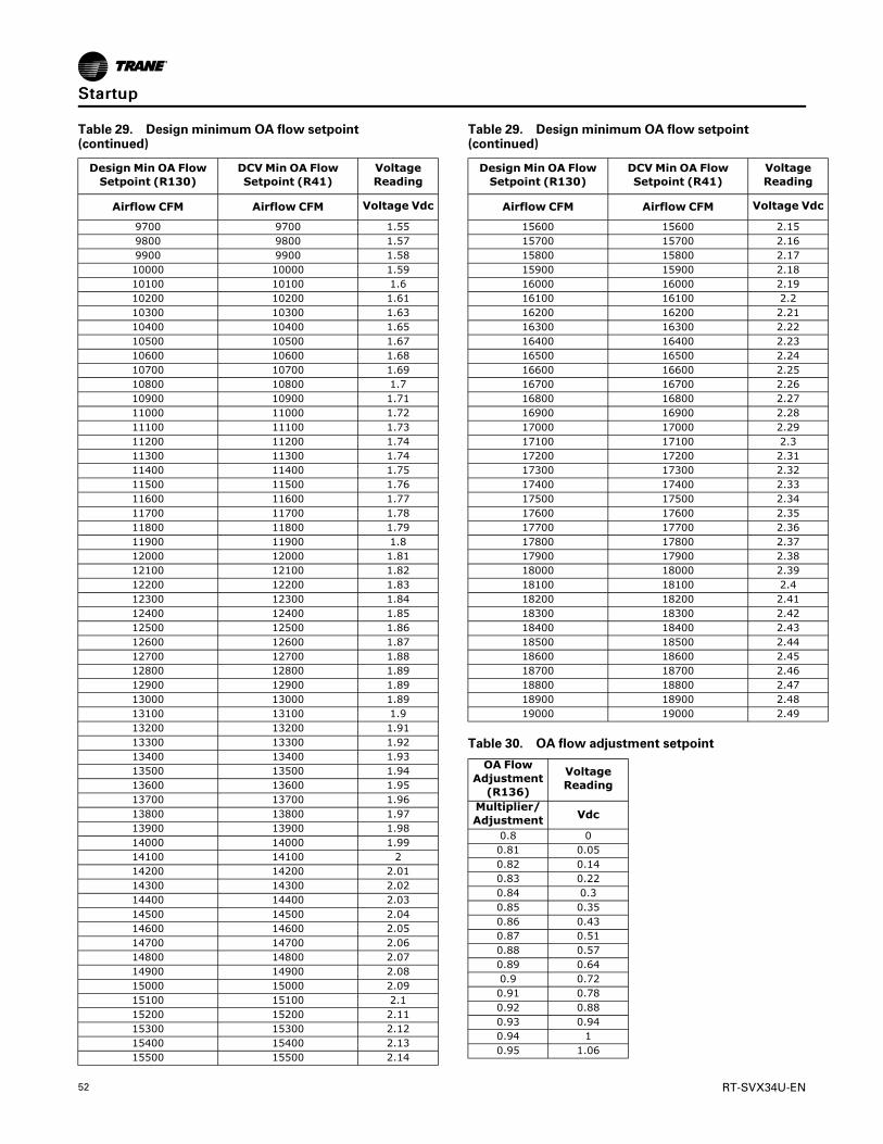
52 RT-SVX34U-EN
Table 29. Design minimum OA flow setpoint(continued)
Design Min OA FlowSetpoint (R130)
DCVMin OA FlowSetpoint (R41)
VoltageReading
Airflow CFM Airflow CFM Voltage Vdc
9700 9700 1.559800 9800 1.579900 9900 1.5810000 10000 1.5910100 10100 1.610200 10200 1.6110300 10300 1.6310400 10400 1.6510500 10500 1.6710600 10600 1.6810700 10700 1.6910800 10800 1.710900 10900 1.7111000 11000 1.7211100 11100 1.7311200 11200 1.7411300 11300 1.7411400 11400 1.7511500 11500 1.7611600 11600 1.7711700 11700 1.7811800 11800 1.7911900 11900 1.812000 12000 1.8112100 12100 1.8212200 12200 1.8312300 12300 1.8412400 12400 1.8512500 12500 1.8612600 12600 1.8712700 12700 1.8812800 12800 1.8912900 12900 1.8913000 13000 1.8913100 13100 1.913200 13200 1.9113300 13300 1.9213400 13400 1.9313500 13500 1.9413600 13600 1.9513700 13700 1.9613800 13800 1.9713900 13900 1.9814000 14000 1.9914100 14100 214200 14200 2.0114300 14300 2.0214400 14400 2.0314500 14500 2.0414600 14600 2.0514700 14700 2.0614800 14800 2.0714900 14900 2.0815000 15000 2.0915100 15100 2.115200 15200 2.1115300 15300 2.1215400 15400 2.1315500 15500 2.14
Table 29. Design minimum OA flow setpoint(continued)
Design Min OA FlowSetpoint (R130)
DCV Min OA FlowSetpoint (R41)
VoltageReading
Airflow CFM Airflow CFM Voltage Vdc
15600 15600 2.1515700 15700 2.1615800 15800 2.1715900 15900 2.1816000 16000 2.1916100 16100 2.216200 16200 2.2116300 16300 2.2216400 16400 2.2316500 16500 2.2416600 16600 2.2516700 16700 2.2616800 16800 2.2716900 16900 2.2817000 17000 2.2917100 17100 2.317200 17200 2.3117300 17300 2.3217400 17400 2.3317500 17500 2.3417600 17600 2.3517700 17700 2.3617800 17800 2.3717900 17900 2.3818000 18000 2.3918100 18100 2.418200 18200 2.4118300 18300 2.4218400 18400 2.4318500 18500 2.4418600 18600 2.4518700 18700 2.4618800 18800 2.4718900 18900 2.4819000 19000 2.49
Table 30. OA flow adjustment setpoint
OA FlowAdjustment(R136)
VoltageReading
Multiplier/Adjustment Vdc
0.8 00.81 0.050.82 0.140.83 0.220.84 0.30.85 0.350.86 0.430.87 0.510.88 0.570.89 0.640.9 0.720.91 0.780.92 0.880.93 0.940.94 10.95 1.06
SSttaarrttuupp

RT-SVX34U-EN 53
Table 30. OA flow adjustment setpoint (continued)
OA FlowAdjustment(R136)
VoltageReading
Multiplier/Adjustment Vdc
0.96 1.10.97 1.180.98 1.220.99 1.251 1.3 - 1.84
1.01 1.861.02 1.891.03 1.921.04 1.961.05 21.06 2.031.07 2.061.08 2.11.09 2.121.1 2.141.11 2.161.12 2.181.13 2.21.14 2.241.15 2.261.16 2.281.17 2.31.18 2.341.19 2.361.2 2.4
Ventilation ControlUnits configured for Single Zone VAV control requirespecial handling of the OA Damper Minimum Positioncontrol in order to compensate for the non-linearity ofairflow associated with the variable supply fan speedand damper combinations.
Demand Controlled VentilationUnits configured for SZVAV and Demand ControlledVentilation (CO2 sensor value available) require a newcontrol scheme comprised of 2 existing schemes thathave been traditionally mutually exclusive; DCV andOA CFM Compensation.
Units configured with DCV will invoke the new DemandControlled Ventilation scheme which allows variableBldg. Design and DCV Minimum Positions and OADamper Position Target setpoints based on the supplyfan speed and space CO2 requirements.
This new scheme will require the setting of 5 OADamper position setpoints; 3 more than on non-SZVAV. These new setpoints are located on the RTVMmodule:
• Design Min Position @ Minimum Fan SpeedCommand (RTVM R130)
• Design Min Position @ Middle Fan SpeedCommand (RTVM R136)
• Design Min Position @ Full Fan Speed Command(RTEM Design Min Position)
• DCV Min Position @ Minimum Fan SpeedCommand (RTVM R41)
• DCV Min position @ Full Fan Speed Command(RTEM DCV Min Position)
As the supply fan speed command varies betweenminimum and maximum, the Building Design and DCVMinimum Position Targets will be calculated linearlybetween the user selected setpoints based on theinstantaneous supply fan speed. The Bldg. Design andDCV Minimum Position Targets will be used tocalculate the Active OA Damper Minimum PositionTarget, as on traditional units, based on the Space CO2relative to the active Design and DCV CO2 setpoints.Refer to Figure 41, p. 54 for additional details on thedesign.
The Design Minimum and DCV Minimum OA DamperPosition setpoints at Minimum Fan Speed Commandand the Design Minimum OA Damper Position setpointat Middle Fan Speed Command will have a range of 0-100% while the Design Minimum and DCV MinimumOA Damper Position setpoints at Full fan speed willhave a range of 0-50%. Note that as on non-SingleZone VAV units, a 10% offset will be enforced betweenthe Design and DCV Minimum Positions throughoutthe fan speed range.
By default, the Design Minimum Position schedule (redline below) will be a linear line through all userselectable Design Minimum Position setpoints. Theuser will have the ability to set the Design MinimumPosition at Middle fan speed command to a point thatwould be lower than the calculated linear line betweenthe Design Minimum Position setpoints at 0% and100% fan speed command in order to compensate forthe non-linear outside airflow through the fan anddamper modulation range. However, if the DesignMinimum Position at Middle fan speed command is setto a point that would be higher than the calculatedlinear line between the Design Minimum Positionsetpoints at Minimum and Full fan speed command,the minimum position will be limited to the point thatwould make the Design Minimum Position schedulelinear.
Provisions have been made in Service Test Mode toallow for proper damper minimum position setup:
• To set the Design and DCV Minimum Positionsetpoints at Minimum Fan Speed, set the unit tooperate at Step 1 (Fan ON) or Step 2 (EconomizerOpen) and make the proper adjustments.
• To set the Design Minimum Position setpoint atMiddle Fan Speed, set the unit to operate at Step 3(Cool 1) and make the proper adjustment.
• To set the Design and DCV Minimum Positionsetpoints at Full Fan Speed, set the unit to operateat Step 4 (Cool 2) and make the proper adjustments.
SSttaarrttuupp
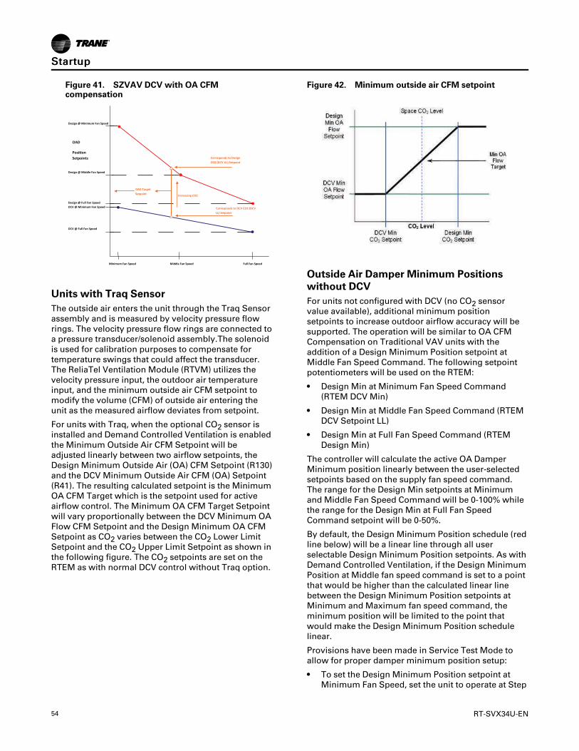
54 RT-SVX34U-EN
Figure 41. SZVAV DCV with OA CFMcompensation
Full Fan Speed Minimum Fan Speed
Design @ Middle Fan Speed
(RTVM R136)
Middle Fan Speed
OAD
Posi!on Setpoints Corresponds to Design
CO2 (DCV UL) Setpoint
Corresponds to DCV CO2 (DCV LL) Setpoint
OAD Target Setpoint Increasing CO2
Design @ Minimum Fan Speed
(RTVM R130)
Design @ Full Fan Speed
(RTEM Design Min.) DCV @ Minimum Fan Speed
(RTVM R41)
DCV @ Full Fan Speed
Units with Traq SensorThe outside air enters the unit through the Traq Sensorassembly and is measured by velocity pressure flowrings. The velocity pressure flow rings are connected toa pressure transducer/solenoid assembly.The solenoidis used for calibration purposes to compensate fortemperature swings that could affect the transducer.The ReliaTel Ventilation Module (RTVM) utilizes thevelocity pressure input, the outdoor air temperatureinput, and the minimum outside air CFM setpoint tomodify the volume (CFM) of outside air entering theunit as the measured airflow deviates from setpoint.
For units with Traq, when the optional CO2 sensor isinstalled and Demand Controlled Ventilation is enabledthe Minimum Outside Air CFM Setpoint will beadjusted linearly between two airflow setpoints, theDesign Minimum Outside Air (OA) CFM Setpoint (R130)and the DCV Minimum Outside Air CFM (OA) Setpoint(R41). The resulting calculated setpoint is the MinimumOA CFM Target which is the setpoint used for activeairflow control. The Minimum OA CFM Target Setpointwill vary proportionally between the DCV Minimum OAFlow CFM Setpoint and the Design Minimum OA CFMSetpoint as CO2 varies between the CO2 Lower LimitSetpoint and the CO2 Upper Limit Setpoint as shown inthe following figure. The CO2 setpoints are set on theRTEM as with normal DCV control without Traq option.
Figure 42. Minimum outside air CFM setpoint
Outside Air Damper Minimum Positionswithout DCVFor units not configured with DCV (no CO2 sensorvalue available), additional minimum positionsetpoints to increase outdoor airflow accuracy will besupported. The operation will be similar to OA CFMCompensation on Traditional VAV units with theaddition of a Design Minimum Position setpoint atMiddle Fan Speed Command. The following setpointpotentiometers will be used on the RTEM:
• Design Min at Minimum Fan Speed Command(RTEM DCV Min)
• Design Min at Middle Fan Speed Command (RTEMDCV Setpoint LL)
• Design Min at Full Fan Speed Command (RTEMDesign Min)
The controller will calculate the active OA DamperMinimum position linearly between the user-selectedsetpoints based on the supply fan speed command.The range for the Design Min setpoints at Minimumand Middle Fan Speed Command will be 0-100% whilethe range for the Design Min at Full Fan SpeedCommand setpoint will be 0-50%.
By default, the Design Minimum Position schedule (redline below) will be a linear line through all userselectable Design Minimum Position setpoints. As withDemand Controlled Ventilation, if the Design MinimumPosition at Middle fan speed command is set to a pointthat would be higher than the calculated linear linebetween the Design Minimum Position setpoints atMinimum and Maximum fan speed command, theminimum position will be limited to the point thatwould make the Design Minimum Position schedulelinear.
Provisions have been made in Service Test Mode toallow for proper damper minimum position setup:
• To set the Design Minimum Position setpoint atMinimum Fan Speed, set the unit to operate at Step
SSttaarrttuupp

RT-SVX34U-EN 55
1 (Fan ON) or Step 2 (Economizer Open) and makethe proper adjustment.
• To set the Design Minimum Position setpoint atMiddle Fan Speed, set the unit to operate at Step 3(Cool 1) and make the proper adjustment.
• To set the Design Minimum Position setpoint at FullFan Speed, set the unit to operate at Step 4 (Cool 2)and make the proper adjustment.
Figure 43. SZVAV OA damper min position w/ OACFM compensation
(RTEM DCV Min)
(RTEM Design Min)
(RTEM DCV Setpoint LL)
Minimum FanSpeed
Middle FanSpeed
Maximum FanSpeed
Design @ Minimum Fan Speed
OADPositionSetpoints
Design @ Middle Fan Speed
Design @ Maximum Fan Speed
Space Pressure ControlFor units configured with an exhaust fan, with orwithout Statitrac, the control described previously foreconomizer minimum position handling requiresadditional changes to the existing Space PressureControl scheme. The overall scheme will remain verysimilar to non-Single Zone VAV units with SpacePressure Control with the exception of a dynamicExhaust Enable Setpoint.
For Single Zone VAV the user will select an ExhaustEnable Setpoint during the Maximum Fan SpeedCommand. Once selected, the difference between theExhaust Enable Setpoint and Design OA DamperMinimum Position at Maximum Fan Speed Commandwill be calculated. The difference calculated will beused as an offset to be added to the Active BuildingDesign OA Minimum Position Target to calculate thedynamic Exhaust Enable Target to be used throughoutthe Supply Fan Speed/OA Damper Position range.
The Exhaust Enable Target could be above or belowthe Active Bldg Design OA Min Position TargetSetpoint based on the Active Exhaust Enable Setpointbeing set above or below the Bldg Design Min Positionat Full Fan Speed Command.
NNoottee:: An Exhaust Enable Setpoint of 0% will result inthe same effect on Exhaust Fan control as onnon-Single Zone VAV applications with andwithout Statitrac.
Figure 44. Space pressure control graph
OADPositionSetpoints
Exhaust Enable Target
Exhaust Enable @ Maximum Fan Speed
Exhaust Enable @Maximum Fan SpeedDesign @ Maximum Fan Speed
Minimum Fan Speed Maximum Fan SpeedMiddle Fan Speed
Fan Speed Algorithm Command
Exhaust EnableO!set
Table 31. RTVM space pressure setpoint
Voltage (Vdc) Setpoint (IWC)0.04 -0.20.118 -0.190.196 -0.180.274 -0.170.352 -0.160.43 -0.150.508 -0.140.586 -0.130.664 -0.120.742 -0.110.82 -0.10.898 -0.090.976 -0.081.02 -0.071.08 -0.061.129 -0.051.178 -0.041.227 -0.031.276 -0.021.325 -0.011.374 01.423 0.011.472 0.021.521 0.031.57 0.041.619 0.051.668 0.061.72 0.071.759 0.081.798 0.091.82 0.11.8565 0.111.893 0.121.9295 0.131.966 0.142.0025 0.152.039 0.162.0755 0.172.112 0.182.1485 0.192.15 0.22.17 0.212.19 0.222.22 0.23
SSttaarrttuupp

56 RT-SVX34U-EN
Table 31. RTVM space pressure setpoint (continued)
Voltage (Vdc) Setpoint (IWC)2.25 0.242.275 0.252.3 0.262.325 0.272.35 0.282.375 0.292.42 0.3
Table 32. RTVM space pressure setpoint deadband
Voltage (Vdc) Setpoint (IWC)0.2 0.020.35 0.030.53 0.040.71 0.050.91 0.061.1 0.071.235 0.081.37 0.091.505 0.11.65 0.111.75 0.121.85 0.131.95 0.142.05 0.152.13 0.162.21 0.172.28 0.182.35 0.192.42 0.2
Traq Overrides and SpecialConsiderationsTraq functionality is not used in unoccupied modesince fresh air control is an occupied ventilationfunction. Damper position will be set to 0% minimumin Unoccupied as with other types of unitconfiguration.
If the Remote Minimum Position pot on the RTEM isshorted (as with NOVAR controls) the Traq minimumdamper position will be overridden to 0% as with otherunit configurations.
Traq functions and sensor value are only valid duringactive Supply Fan operation therefore a value of "0CFM" will be substituted for any low level (bleedthrough) sensor value that may be sensed on the OAFlow Sensor during "Fan OFF" periods. OA DamperMinimum Position is only valid during active fanoperation in all configurations.
The Design Min OA Flow Setpoint will be limited to alower limit of 1,000 CFM and an upper limit of 20,000CFM. Setting of values outside of this range, except for"0 CFM", will result in the setting being clamped withinthe range. A value of "0" CFM will be allowed and willresult in initialization of the Traq OA Damper MinPosition calculation, and an active value of “0%” will besent as the Active Traq setpoint. This allows the user to
set the damper closed by setting the flow setpoint to 0CFM.
If Demand Controlled Ventilation is configured then thelower limit of the Design Min OA Flow Setpoint will be1,500 CFM to allow a gap to the DCV Min OA FlowSetpoint of 500 CFM making its lower limit 1,000 CFM.When the Design Min OA Flow Setpoint is greater than1,500 CFM a minimum of 500 CFM offset will beenforced between the DCV Min OA Flow Setpoint andthe Design Min OA Flow Setpoint.
If configured for Traq operation and OA CFMCompensation, the unit will perform Traq control sinceit will be the most accurate method of control. Thissituation might occur if a unit is upgraded to Traqcontrol, but the OA CFM Compensation config jumperon the RTEM is left on. It will be assumed by thepresence of a valid OA CFM Flow Sensor and the RTVMversion that supports Traq is accompanied by all thenecessary unit equipment upgrades.
Supply Air Temperature Control -Heating and CoolingFor Cooling, Heating (Modulating Heat Only), and HotGas Reheat operation the unit will control the activecapacity outputs to meet a varying, calculatedDischarge Air Setpoint that is calculated based on zoneconditions in order to maintain the Zone Temperatureto the active Zone Setpoint. Note that this setpoint willbe clamped between the user selected DA Heat and DACool - Fan Speed setpoints that are set on the RTOM forcompressor and economizer control. In general, as thezone temperature rises above the ZCSP, the ActiveDischarge Air Setpoint will be calculated down and asthe zone temperature falls below the ZHSP Tset will becalculated upward. This calculated setpoint is a directindication of space demand and is also used todetermine the proper supply fan speed to meet thespace requirements. During active capacity control, theunit will utilize a +/- 3.5°F deadband around the activeDischarge Air Setpoint to determine when to requestadditional heating or cooling capacity similarly totraditional VAV control, as described below. If the unitis maintaining the discharge air temperature within the+/- 3.5°F deadband around the calculated discharge airsetpoint requirements, no additional capacity will berequested.
The calculated setpoint will also be used for activeeconomizer control, but the economizer will utilize atighter control deadband (+/- 1.5°F) than that is used forcompressor output control. Also, as on Traditional VAVunits, mechanical cooling will be inhibited ifeconomizing is enabled until the economizer has beenfull open for 3 minutes.
SSttaarrttuupp

RT-SVX34U-EN 57
Variable Air VolumeApplications (Traditional VAV)Supply Air Temperature Control -Occupied Cooling and HeatingThe RTRM is designed to maintain a selectable supplyair temperature of 40°F to 90°F with a +/- 3.5°Fdeadband. In cooling, if supply air temperature is morethan 3.5 degrees warmer than the selectedtemperature, a stage of cooling will be turned “On” (ifavailable). Then if the supply air temperature is morethan 3.5 degrees cooler than the selected temperature,a stage of cooling will be turned “Off”.
At very low airflows the unit may cycle stages “On”and “Off” to maintain an average discharge airtemperature outside the 7 degree deadband.
If the unit has modulating heat, the unit can be made todo discharge heating with VAV control. This is done byplacing a contact closure across the “ChangeoverInput” on the RTAM. During this mode, the unit willheat to the Supply Air Heating Setpoint +/- 3.5°F.During low load or low airflow conditions the actualtemperature swing of the discharge air will likely begreater.
The RTRM utilizes a proportional and integral controlscheme with the integration occurring when the supplyair temperature is outside the deadband. As long as thesupply air temperature is within the setpoint deadband,the system is considered to be satisfied and no stagingup or down will occur.
Supply Air Temperature Control with anEconomizerThe economizer is utilized to control the supply aircooling at +1.5°F around the supply air temperaturesetpoint range of 40°F and 90°F providing the outsideair conditions are suitable.
While economizing, the mechanical cooling is disableduntil the economizer dampers have been fully open forthree minutes. If the economizer is disabled due tounsuitable conditions, the mechanical cooling willcycle as though the unit had no economizer.
VHR Relay OutputDuring unoccupied mode, daytime warm-up (DWU)and morning warm-up (MWU) the VFD will open to100%. All VAV boxes must be opened through an ICSprogram or by the VHR wired to the VAV boxes. TheRTRM will delay 100% fan operation approximately 6.5minutes when switching from occupied cooling modeto a heating mode.
Zone Temperature Control without aNight Setback Panel or ICS - UnoccupiedCoolingWhen a field supplied occupied/unoccupied switchingdevice is connected between RTRM J6-11 and RTRMJ6-12, both the economizer and the mechanical coolingwill be disabled.
Zone Temperature Control without aNight Setback Panel or ICS - UnoccupiedHeatingWhen a field supplied occupied/unoccupied switchingdevice is connected between RTRM J6-11 and J6-12and DWU is enabled, the zone temperature will becontrolled at 10°F below the Morning Warm-upsetpoint, but not less than 50°F, by cycling one or twostages of either gas or electric heat, whichever isapplicable.
Morning Warm-up (MWU) ControlMorning Warm-up is activated if the zone temperatureis at least 1.5°F below the MWU setpoint whenever thesystem switches from Unoccupied to Occupied status.The MWU setpoint may be set from the unit mountedpotentiometer or a remotely mounted potentiometer.The setpoint ranges are from 50°F to 90°F. When thezone temperature meets or exceeds the MWU setpoint,the unit will switch to the “Cooling” mode. Theeconomizer will be held closed during the morningwarm-up cycle.
Daytime Warm-up (DWU) ControlDaytime Warm-up is applicable during occupied statusand when the zone temperature is below the initiationtemperature. It can be activated or deactivated throughICS or a night setback zone sensor. If ICS or a nightsetback zone sensor is not utilized, DWU can beactivated by setting the DWU enable DIP switch(RTAM) to ON and supplying a valid morning warm-upsetpoint.
The unit is shipped with a Morning Warm-up setpointconfigured and the Daytime Warm-up function isactivated (switch on). Opening the DWU enable switchwill disable this function.
If the system control is local, the DWU initiationsetpoint is 3°F below the Morning Warm-up setpoint.The termination setpoint is equal to the MorningWarm-up setpoint.
If the system control is remote (Tracer®), the DWUsetpoint is equal to the Tracer Occupied heatingsetpoint. The initiation and termination setpoints areselectable setpoints designated by Tracer.
When the zone temperature meets or exceeds thetermination setpoint while the unit is in an Occupied,“Auto” Mode or switched to the “Cooling” Mode, theunit will revert to the cooling operation.
SSttaarrttuupp

58 RT-SVX34U-EN
If an Occupied “Heating” Mode is selected, the unit willonly function within the DWU perimeters until thesystem is switched from the “Heat” Mode or enters anUnoccupied status.
NNoottee:: When a LCI is installed on a VAV unit, the MWUsetpoint located on the RTAM board is ignored.The MWU and DWU setpoints come from thehigher priority LCI-R DAC.
Supply Duct Static Pressure ControlThe supply duct static pressure is measured by atransducer with a 0.25 to 2.125 Vdc proportional outputwhich corresponds to an adjustable supply duct staticpressure of 0.3" w.c. to 2.5" w.c. respectively with adeadband adjustment range from 0.2" w.c. to 1.0" w.c.The setpoint is adjustable on the RTAM Static PressureSetpoint potentiometer or through ICS.
Example:Supply Duct Static setpoint = 2.0" w.c. (RTAM)Deadband = 0.2" w.c. (RTAM)Duct Static Control Range = 1.9" w.c. to 2.1" w.c.
Figure 45. Output vs. input
Transducer Voltage Output vs Pressure Input
0.00.51.01.52.02.53.03.54.04.5
-0.5 0.0 0.5 1.0 1.5 2.0 2.5 3.0 3.5 4.0 4.5 5.0 5.5Pressure (inches w.c.)
Vol
ts
Supply Air Temperature ResetThe supply air temperature can be reset by using oneof four DIP switch configurations on the RTAM orthrough ICS when a valid supply air reset setpoint witha supply air reset amount is given. A selectable resetamount of 0° F to 20°F via RTAM potentiometer or ICSis permissible for each type of reset.
The amount of change applied to the supply airtemperature setpoint depends on how far the returnair, zone, or outdoor air temperature falls below thereset temperature setpoint. If the return air, zone, oroutdoor air temperature is equal to or greater than thereset temperature setpoint, the amount of change iszero.
If the return air, or zone temperature falls 3°F below thereset temperature setpoint, the amount of reset appliedto the supply air temperature will equal the maximumamount of reset selected.
If the outdoor air temperature falls 20°F below the resettemperature setpoint, the amount of reset applied tothe supply air temperature will equal the maximumamount of reset selected. The four DIP switchconfigurations are as follows:
• None - When RTAM DIP Switch #3 and #4 are in the“Off” position, no reset will be allowed.
• Reset based on Return Air Temperature - WhenRTAM DIP Switch #3 is “Off” and Switch #4 is “On”,a selectable supply air reset setpoint of 50°F to 90°Fvia a unit mounted potentiometer or Tracer® ispermissible.
• Reset based on Zone Temperature - When RTAMDIP Switch #3 is “On” and Switch #4 is “Off”, aselectable supply air reset setpoint of 50°F to 90°Fvia RTAM potentiometer or Tracer is permissible.
• Reset based on Outdoor Air Temperature - WhenDIP Switch #3 and #4 are “On”, a selectable supplyair reset setpoint of 0°F to 100°F via RTAMpotentiometer or Tracer is permissible.
VAV Supply Air Tempering (OnlyAvailable with Modulating Gas Heat)The gas heater will be modulated to prevent theDischarge Air Temperature from falling below theDischarge Temperature Deadband. Upon satisfying theSupply Air Tempering requirements, a 5 minute SATempering Delay timer will start whenever themodulating gas heat combustion blower iscommanded to 0 and must time out before the unit willbe allowed to re-enter “Cool” mode. This timer will bereset to 5 minutes whenever there is an active call for“Supply Air Tempering”. Tempering will bediscontinued whenever;
• The 5 minutes “Supply Air Tempering Delay” timerhas timed-out and;
• There is an active cooling request for VAV OccupiedCooling.
Constant Volume or Variable AirVolume Applications (SingleZone or Traditional)Off ModeThis mode is set at the zone sensor or by ICS. Duringthis status, no heating, ventilation, or mechanicalcooling is being performed. When switching the“System” selector to the ““OOffff”” mode from any othermode, any diagnostic data and diagnostic indicationsignal will be retained as long as the system remains inthe ““OOffff”” status. Switching the “System” selector fromthe ““OOffff”” mode back to any other mode of operationwill reset all diagnostics.
SSttaarrttuupp

RT-SVX34U-EN 59
Zone Temperature - Unoccupied Cooling(CV or SZ VAV Only)While a building is in an unoccupied period asdesignated by a remote panel with night setback, ICSor RTRM J6-11 and J6-12, the necessary coolingcapacity will be controlled to maintain the zonetemperature to within the unoccupied setpointdeadband. If an economizer is enabled, it will modulatein an attempt to maintain the zone temperature towithin the setpoint deadband.
NNoottee:: On SZ VAV units, the Supply Air Fan Speed willbe controlled as during normal occupiedconditions in order to meet the requirements ofthe zone. Unoccupied mode does not require fullairflow on a SZ VAV unit during Coolingoperation.
Zone Temperature - Unoccupied HeatingWhile a building is in an unoccupied period asdesignated by a remote panel with night setback orICS, the necessary heating capacity will be controlledto maintain the zone temperature to within theunoccupied setpoint deadband. For traditional VAVsystems, the VFD will operate at 100% during thismode. It will be necessary to drive VAV boxes to theirmaximum position through ICS programming or thefactory provided VHR relay. For SZ VAV systems, theSupply Air Fan VFD will remain in control as duringnormal occupied periods and will be controlled in orderto meet the space requirements. The minimum fanspeed will be based on the configured unit heatingtype. For Modulating Heat units, Full Airflow is notrequired for SZ VAV applications during Unoccupiedperiods. For all Staged Heating types, the Supply Fanwill be controlled at maximum fan speed during activeheating operation as during Occupied periods.
Mechanical Cooling with an EconomizerThe economizer is utilized to control the zonetemperature when the outside air conditions aresuitable. The method used to determine economizereffectiveness, depending on the available data, isdescribed below in descending order of complexity.The most sophisticated method available is alwaysused.
Table 33. Economizer effectiveness
Method used todetermine economizer
effectiveness Required
Comparative Enthalpy OAT, OAH, RAT, RAH
Reference Enthalpy OAT, OAH
Reference Dry Bulb OAT
Unable to determineeffectiveness
OAT data is invalid orunavailable
Two of the three methods for determining thesuitability of the outside air can be selected utilizing thepotentiometer on the Economizer Actuator, asdescribed below:
• Ambient Temperature - controlling the economizingcycle by sensing the outside air dry bulbtemperature. Table 34, p. 59 lists the selectable drybulb values by potentiometer setting.
• Reference Enthalpy - controlling the economizercycle by sensing the outdoor air humidity. Table34, p. 59 lists the selectable enthalpy values bypotentiometer setting. If the outside air enthalpyvalue is less than the selected value, theeconomizer is allowed to operate.
• Comparative Enthalpy - By utilizing a humiditysensor and a temperature sensor in both the returnair stream and the outdoor air stream, theeconomizer will be able to establish whichconditions are best suited for maintaining the zonetemperature, i.e., indoor conditions or outdoorconditions.
Table 34. Economizer configuration
PotentiometerSetting Point
Dry bulbchangeover
Point
ReferenceEnthalpy
A 73°F 27 BTU/lb.
B 70°F 25 BTU/lb.
C(a) 67°F 23 BTU/lb.
D 63°F 22 BTU/lb.
E 55ºF 19 BTU/lb.
(a) Factory setting
Gas Heat ControlThe ignition sequence and timing are provided by aseparate heat control module. The RTRM only providesthe heating outputs to initiate 1st and 2nd stages andcontrol the combustion blower relays. Both stages ofthe furnace, when initiated after each cycle, will startand operate for one minute then cycle back if only onestage is required. Units with modulating heatcapabilities will light on high fire for one minute andthen modulate to the appropriate heating rate for thebuilding load present.
When the fan selection switch is in the ““AAUUTTOO”” modeand the unit is configured as a Constant Volume withstaged or modulating gas heat, or SZVAV with stagedgas heat, the fan will be delayed from coming on forapproximately 30 seconds after a call for heat has beeninitiated. The fan will remain on for approximately 90seconds after the heating setpoint has been satisfied. Ifthe unit is configured for SZ VAV with modulating heat,the fan will be energized with the call for heating inorder to begin circulating airflow through the unit fordischarge air temperature control. Once the call for
SSttaarrttuupp

60 RT-SVX34U-EN
heating is removed, the fan will remain on forapproximately 90 seconds.
Electric Heat ControlThe RTRM provides two heating outputs for 1st and2nd stages that will be controlled with at least a 10seconds delay between each stage. When the fanselection switch is in the ““AAUUTTOO”” mode and the unit isconfigured for Constant Volume, the fan will startapproximately 1 second before the 1st heater stage isactivated. The fan and heater will cycle off after theheating setpoint has been satisfied. If the unit isconfigured for SZ VAV control, the Supply Fan willenergize approximately 5 seconds prior to energizingthe electric heat outputs. Once the Zone Heatingrequirements have been satisfied, the fan and heatoutputs will be controlled off.
Clogged Filter OptionThe unit mounted clogged filter switch monitors thepressure differential across the return air filters. It ismounted in the filter section and is connected to theRTOM. The switch is adjustable and can be set for aparticular application. The clogged filter switch isnormally open and will automatically close when thepressure differential across the filters falls below theclogged filter setpoint. The RTOM will generate aSERVICE diagnostic that will be sent to the zone sensoror remote panel when the clogged filter switch hasbeen closed for at least 2 minutes during supply fanoperation. The system will continue to operateregardless of the status of the clogged filter switch.
Ventilation OverrideNNoottee:: Applying 24 volts to one of the three Ventilation
Override Inputs manually activates ventilationoverride. One input is provided to request thePressurize Mode, the second input the PurgeMode, and the third input the Exhaust Mode.
When the Pressurize Mode is selected, activatingVentilation Override will cause the supply fan to run,the economizer to open to 100%, the exhaust fan toturn (remain) off, or the VFD to run at full speed (SZVAV and Traditional VAV), and the VAV boxes to fullyopen.
When Purge is selected, activating Ventilation Overridewill cause the supply fan to run, the economizer toopen to 100%, the exhaust fan to run, or the VFD to runat full speed (SZ VAV or Traditional VAV), and the VAVboxes to fully open.
When Exhaust is selected, activating VentilationOverride will cause the supply fan to turn off, theeconomizer to close to 0%, the exhaust fan to run(exhaust damper at 100% if configured for Statitrac), orthe VFD to stop, and the VAV boxes to operatenormally.
If more than one mode is requested at the same time,the Pressurize request will have priority followed byPurge. When any Ventilation Override Mode is active,all heating and cooling is turned off. For the case wherethe unit is required to turn off, the Emergency Stopinput is used. The ICS can also initiate any ventilationoverride mode. Table 35, p. 60 lists the sequence ofevents within the system for each ventilation mode.Refer to the unit wiring diagram for contact switchingand wiring.
NNoottee:: Fresh air tracking will not work with VOM.
Table 35. Ventilation override sequence
AffectedFunction
Mode and Priority
Pressurize Purge Exhaust(a)
1 2 3
Heat/Cool off off off
VFD full speed full speed full speed
Supply Fan on on off
Exhaust Fan off on(b) on
Economizer open open closed
VAV Boxes forced open forced open normaloperation
(a) Exhaust mode 3 is not available with the tracking power exhaustoption.
(b) For units configured with the Statitrac option, the Exhaust Damperwill open during Ventilation Override modes that request the ex-haust fan to operate.
Emergency StopWhen this binary input is opened, all outputs areimmediately turned off and the system will not beallowed to restart until the binary input is closed forapproximately 5 seconds minimum. The shut down iscommunicated to Tracer® if applicable and the Heatand Cool LED outputs (RTRM J6-7 and J6-8) will blinkat a nominal rate of 1 blink per second.
Phase MonitorThe Phase Monitor is a 3 phase line monitor modulethat protects against phase loss, phase reversal andphase unbalance. It is intended to protect compressorsfrom reverse rotation. It has an operating input voltagerange of 190-600 VAC, and LED indicators for ON andFAULT. There are no field adjustments and the modulewill automatically reset from a fault condition.
Low Pressure ControlThis input incorporates the low pressure cutout of eachrefrigeration circuit and can be activated by opening afield supplied contact.
If this circuit is open before a compressor(s) is started,neither compressor in that circuit will be allowed tooperate.
SSttaarrttuupp

RT-SVX34U-EN 61
Anytime this circuit is opened for 5 continuousseconds, the compressor(s) in that circuit are turned offimmediately. The compressor(s) will not be allowed torestart for a minimum of 3 minutes.
If four consecutive open conditions occur during thefirst three minutes of operation, the compressor(s) inthat circuit will be locked out, a diagnosticcommunicated to Tracer, and a manual reset will berequired to restart the compressor(s).
The hot gas reheat option has one reheat low pressurecutout (RLP). The RLP is located on the reheat circuit.
Hot Gas Reheat Low Pressure ControlThe RLP has been added to insure proper refrigerantmanagement during active modulating hot gas reheatoperation.
The RLP will be ignored for the first 10 minutes ofcompressor run time during active hot gas reheatoperation. Anytime this circuit is opened for 5continuous seconds, the compressor(s) in that circuitare turned off immediately. The compressor(s) will notbe allowed to restart for a minimum of 3 minutes. Iffour consecutive open conditions occur during activehot gas reheat, the compressor(s) in that circuit will belocked out.
High Pressure Cutout and TemperatureDischarge LimitThe high pressure controls and temperature dischargelimit are wired in series between the compressoroutputs on the RTRM and the compressor contactors.On 27.5, 30, and 35 Ton units, if the high pressuresafety switch or temperature discharge limit opens, theRTRM senses a lack of current while calling for coolingand locks both compressors out with an auto reset. On40 and 50 Ton units, if the high pressure safety ortemperature discharge limit opens, the compressor(s)on the affected circuit is locked out. If the compressoroutput circuit is opened four consecutive times duringcompressor operation, the RTRM will generate amanual reset lockout.
Power Exhaust ControlThe power exhaust fan is started whenever the positionof the economizer dampers meets or exceed the powerexhaust setpoint when the supply fan is on.
The setpoint potentiometer is on the RTOM and isfactory set at 25% for traditional constant volume andvariable air volume units.
For SZ VAV units the default power exhaust enablesetpoint will be 25% as on non-SZ VAV units. However,for SZ VAV the Exhaust Enable Setpoint will need to beadjusted for the proper setpoint during the maximumFan Speed Command for the unit. Once selected, thedifference between the Exhaust Enable Setpoint andDesign OA Damper Minimum Position at Full FanSpeed Command will be calculated. The difference
calculated will be used as an offset to be added to theActive Building Design OA Minimum Position target tocalculate the Dynamic Exhaust Enable Target to beused throughout the Supply Fan Speed/OA DamperPosition range:
Exhaust Enable Target = Active Bldg Design OA MinPosition Target + (Active Exhaust Enable Setpoint –Active Bldg Design OA Min Position @ Full Fan SpeedCommand)
The Exhaust Enable Target could be above or belowthe Active Bldg Design OA Min Position TargetSetpoint based on the Active Exhaust Enable Setpointbeing set above or below the Bldg Design Min Positionat Full Fan Speed Command. Note that an ExhaustEnable Setpoint of 0% will result in the same effect onExhaust Fan control as on non-Single Zone VAVapplications with and without Statitrac; Exhaust FanON. See Figure 46, p. 61 for how the exhaust enablesetpoint is modified throughout the OA damperoperating range.
Figure 46. SZ VAV exhaust
Maximum Fan Speed Minimum Fan Speed Middle Fan Speed
OAD Posi!on
Setpoints
Design @ Full Fan Speed
Exhaust Enable Offset
Exhaust Enable @ Full Fan Speed
Exhaust Enable Target
Space Pressure Control - StatitracA pressure transducer is used to measure and reportdirect space (building) static pressure. The user-definedcontrol parameters used in this control scheme areSpace Pressure Setpoint and Space PressureDeadband. As the Economizer opens, the buildingpressure rises and enables the Exhaust Fan. TheExhaust dampers will be modulated to maintain SpacePressure within the Space Pressure Deadband.
NNoottee:: The Exhaust Enable setpoint will need to beselected as on units with standard powerexhaust control.
SSttaarrttuupp

62 RT-SVX34U-EN
Figure 47. Transducer voltage output vs. pressureinput for building pressure
Power Exhaust Control (Tracking)The power exhaust dampers proportionally track orfollow the fresh air (economizer) damper position. Theoffset between the fresh air and the exhaust damper(s)is adjustable, see figures beginning with Figure 54, p.84. Refer to Power Exhaust Fan Performance” tablesbeginning with Table 53, p. 83.
Lead/Lag ControlLead/Lag is a selectable input located on the RTRM. On2 & 3 stage standard efficiency units, the RTRM isconfigured from the factory with the Lead/Lag controldisabled. To activate the Lead/Lag function, simplyremove the jumper connection J3-8 at the RTRM Lead/Lag input. When it is activated, each time thedesignated lead compressor(s) is shut off due to theload being satisfied, the lead compressor orrefrigeration circuit switches. On the 5 stage highefficiency units, the RTRM is configured from thefactory with the Lead/Lag control enabled. With itactive, each time the designated lead compressor isshut off due to the load being satisfied, the controls willswitch to the next staging sequence. When the RTRM ispowered up, i.e. after a power failure, the control willdefault to the number one compressor.
Table 36. Capacity steps with lead/lag enabled - stdEfficiency
Unit Size Step 1 Step 2 Step 3
TC*330LEAD 48% 100%
LAG 52% 100%
TC*360LEAD 50% 100%
LAG 50% 100%
TC*420LEAD 47% 100%
LAG 53% 100%
TC*480 VAVonly
LEAD 40% 60%100%
LAG 60% 100%
Table 36. Capacity steps with lead/lag enabled - stdEfficiency (continued)
Unit Size Step 1 Step 2 Step 3
TC*600 VAVonly
LEAD 32% 68%100%
LAG 68% 100%
Table 37. Capacity staging sequence - high Efficiencyand 40–50 tons std eff CV
Steps
Unit Size Sequence 1 2 3 4 5
TC*330
1 25 37 63 75 100
2 37 63 75 100
3 37 63 75 100
TC*360
1 24 38 62 76 100
2 38 62 76 100
3 38 62 76 100
TC*420
1 22 39 61 78 100
2 39 61 78 100
3 39 61 78 100
TC*480
1 23 39 61 77 100
2 39 61 77 100
3 39 61 77 100
TC*600
1 25 38 62 75 100
2 38 62 75 100
3 38 62 75 100
Coil Frost ProtectionThe Frostat™ control monitors the suction linetemperature to prevent the evaporator from freezingdue to low operating temperatures whenever there is ademand for cooling. When a closed circuit hasoccurred for 5 seconds minimum, the RTRM turns offall of the cooling outputs. The Supply Fan will be held““OOnn”” until the Frostat has been open for 5 continuousseconds or for 60 seconds after the last compressorwas shut ““OOffff””, whichever is the longest. Thecompressor shutdown is communicated to Tracer, ifapplicable. There is no local diagnostic for thiscondition.
Modulating Hot Gas Reheat FrostProtectionTwo control schemes will be active on units configuredfor Modulating Hot Gas Reheat. The first employs theuse of the Frostat function. The second scheme takesprecedence over Frostat. Operation will be as describedbelow.
The second scheme is in control during active hot gasreheat or cooling and includes the use of an Entering
SSttaarrttuupp

RT-SVX34U-EN 63
Evaporator Temperature sensor (EET). If the EET dropsbelow 35°F for 10 continuous minutes compressors willstage off. For dual circuit units one circuit will bestaged off initially, and then if the EET remains below35ºF for an additional 10 minutes, the second circuitwill be staged off. For single circuit units onecompressor will be staged off initially, and then if theEET remains below 35ºF for an additional 10 minutes,the second circuit will be staged off. When the unit isoperating in hot gas reheat mode, only the reheatcircuit will be re-enabled if the EET rises above 45ºF.The cooling circuit will not be re-enabled during hotgas reheat until the unit leaves the current hot gasreheat cycle or a dehumidification purge is initiated. Ifthe unit is operating in Cooling, the first circuit that de-energized will be re-enabled when the EET rises above45ºF. The second compressor will be allowed to re-energize at 10 minutes after the EET rises above 45ºF orif a purge cycle is initiated.
Drain Pan Condensate Overflow Switch(Optional)This input incorporates the Condensate OverflowSwitch (COF) mounted on the drain pan and theReliaTel Options Module (RTOM). When thecondensate level reaches the trip point for 6 continuousseconds, the RTOM will shut down all unit functionuntil the overflow condition has cleared. The unit willreturn to normal operation after 6 continuous secondswith the COF in a non-tripped condition. If thecondensate level causes the unit to shutdown morethan 2 times in a 3 day period, the unit will be locked-out of operation. A manual reset of the diagnosticsystem through the Zone Sensor or Building
Automation System (BAS) will be required. Cycling unitpower will also clear the fault.
VFD Programming ParametersSee System Troubleshooting section.
Condenser Fan Sequencing ControlThe condenser fans are cycled according to theoutdoor air temperature and the number of coolingsteps that are operating. Table 38, p. 63 and Table 39,p. 65 list the temperatures at which the A and BCondenser Fan Outputs on the RTRM switches the fans“Off”. The fans are switched back “ON” when theoutdoor temperature rises approximately 5° F abovethe “Off” temperature.
Figure 48, p. 63 shows the condenser fans as viewedfrom the top of the unit facing the control panel.Whenever a condenser fan is cycled back “On”, thecondenser fan Outputs A and B and the compressorsteps are de-energized for approximately sevenseconds to prevent problems with fan windmill.
Figure 48. Condenser fan location
Lead fancontinuous operation
Control box
Table 38. Condenser fan/compressor sequence - std efficiency
Unit Size(Ton)
Compressor Staging Sequence Condenser Fan Output O/A Temp. (°F)
Step 1 Step2 Step 3 Output A Output B Fans “Off”
27.5 - 30
CPR1(a)
NA
Fan #2 70
Fan #3 90
CPR1, 2Fan #2 -10
Fan #3 60
35
CPR1(a)
NA
Fan #2 65
Fan #3 85
CPR1, 2Fan #2 -20
Fan #3 55
40 VAV only
CPR1(b)Fan #2 50
Fan #3, 4 70
CPR2(c)Fan #2 20
Fan #3, 4 60
CPR1, 2Fan #2 -30
Fan #3, 4 50
SSttaarrttuupp

64 RT-SVX34U-EN
Table 38. Condenser fan/compressor sequence - std efficiency (continued)
Unit Size(Ton)
Compressor Staging Sequence Condenser Fan Output O/A Temp. (°F)
Step 1 Step2 Step 3 Output A Output B Fans “Off”
50 VAV only
CPR1(b)Fan #2 20
Fan #3, 4 60
CPR2, 3(d)Fan #2 -10
Fan #3, 4 55
CPR1, 2, 3Fan #2 -30
Fan #3, 4 50Notes:
1. The compressor(s) listed under each step are the operating compressors. On 27.5 to 35 Ton units with Lead/Lag,CPR1 will alternate but the fan sequence will remain the same. On 40 & 50 Ton units with Lead/Lag, the compressor(s) in step 2 & 3 will alternate and the fan sequence listed for that step will be in operation.
2. Conventional thermostat sequence: Y1=CPR1, Y2=CPR2 (40 CPR 2 & 50 CPR 2,3), Y1 + Y2 = CPR1,2 (40 CPR 1,2 &50 CPR 1,2,3)
3. During active hot gas reheat all compressors will be staged “On”. For units equipped with four condenser fans (40and 50 Ton), the condenser fan output states will be controlled based on the O/A temperature. If O/A is above 85°F,all condenser fan outputs will be energized. If O/A falls below 80°F, Output B will de-energize and will not re-energize again until the O/A rises above 85°F. For units configured with three condenser fans (27.5 to 35 Ton), amaximum of two condenser fans will energize. Output A will energize above 85°F and de-energize when the O/Afalls below 80°F; Output B will remain de-energized during active hot gas reheat. If O/A falls below 80°F, Output Awill de-energize and will not re-energize again until O/A rises above 85°F.
(a) Single circuit, manifolded compressors pair.(b) First Stage, Number one refrigeration circuit, Standalone compressor is “On”.(c) First Stage is “Off”, Number two refrigeration circuit, standalone compressor is “On”.(d) First stage is “Off”, Number two refrigeration circuit, manifolded compressor pair is “On” operating simultaneously.
SSttaarrttuupp

RT-SVX34U-EN 65
Table 39. Condenser fan/compressor sequence - high efficiency
27.5-35 Ton High Efficiency
Compressor Stage 1 Compressor Stage 2
Fan #1 Fan #2 Fan #3AmbientRange (F)
# CondFans On Fan #1 Fan #2 Fan #3
AmbientRange (F)
# CondFans On
ON
OFF OFF 0-70 1
ON
OFF OFF 0-58 1OFF OFF 70-75 1 or 2 OFF OFF 58-63 1 OR 2ON OFF 75-80 2 ON OFF 63-70 2ON OFF 80-85 2 or 3 ON OFF 70-75 2 OR 3ON ON 85-115 3 ON ON 75-115 3
27.5-35 Ton High Efficiency
Compressor Stages 3 or 4 Compressor Stage 5
Fan #1 Fan #2 Fan #3AmbientRange (F)
# CondFans On Fan #1 Fan #2 Fan #3
AmbientRange (F)
# CondFans On
ON
OFF OFF 0-60 1
ON
OFF OFF 0-50 1OFF OFF 60-65 1 OR 2 OFF OFF 50-55 1 OR 2ON OFF 65-70 2 ON OFF 55-60 2ON OFF 70-75 2 OR 3 ON OFF 60-65 2 OR 3ON ON 75-115 3 ON ON 65-115 3
40 Ton High Eff. and Std Eff. CV
Compressor Stages 1 & 2 Compressor Stages 3 & 4
Fan #1 Fan #2 Fan #3 & 4AmbientRange (F)
# CondFans On Fan #1 Fan #2 Fan #3 & 4
AmbientRange (F)
# CondFans On
ON
OFF OFF 0-60 1
ON
OFF OFF 0-40 1OFF OFF 60-70 1 or 2 OFF OFF 40-45 1 OR 2ON OFF 70-80 2 ON OFF 45-75 2ON OFF 80-85 2 or 4 ON OFF 75-80 2 OR 4ON ON 85-115 4 ON ON 80-115 4
40 Ton High Eff. and Std Eff. CV 50 Ton High Eff. and Std Eff. CV
Compressor Stage 5 Compressor Stages 1 & 2
Fan #1 Fan #2 Fan #3 & 4AmbientRange (F)
# CondFans On Fan #1 Fan #2 Fan #3 & 4
AmbientRange (F)
# CondFans On
ON
OFF OFF 0-40 1
ON
OFF OFF 0-60 1OFF OFF 40-45 1 OR 2 OFF OFF 60-65 1 or 2ON OFF 45-65 2 ON OFF 65-75 2ON OFF 65-70 2 OR 4 ON OFF 75-80 2 or 4ON ON 70-115 4 ON ON 80-115 4
50 Ton High Eff. and Std Eff. CV
Compressor Stages 3 & 4 Compressor Stage 5
Fan #1 Fan #2 Fan #3 & 4AmbientRange (F)
# CondFans On Fan #1 Fan #2 Fan #3 & 4
AmbientRange (F)
# CondFans On
ON
OFF OFF 0-35 1
ON
OFF OFF 0-35 1OFF OFF 35-40 1 OR 2 OFF OFF 35-40 1 OR 2ON OFF 40-70 2 ON OFF 40-60 2ON OFF 70-75 2 OR 4 ON OFF 60-65 2 OR 4ON ON 75-115 4 ON ON 65-115 4
Notes:1. Condenser fan will de-energize at 5ºF below the energizing temperature2. Compressor Stage 1 = CPR13. Compressor Stage 2 = CPR2 or CPR3 depending on staging sequence4. Compressor Stage 3 = CPR1 & CPR2 or CPR2 & CPR3 depending on staging sequence5. Compressor Stage 4 = CPR2 & CPR36. Compressor Stage 5 = CPR1 & CPR2 & CPR37. Conventional three stage thermostat sequence: Y1=CPR1 (Stage 1), Y2=CPR1&2 (Stage 3), Y1 + Y2 = CPR1,2,3 (Stage 5)8. During active hot gas reheat all compressors will be staged “On”. For units equipped with four condenser fans (40 and 50 Ton), the
condenser fan output states will be controlled based on the O/A temperature. If O/A is above 85°F, all condenser fan outputs will beenergized. If O/A falls below 80°F, Output B will de-energize and will not re-energize again until the O/A rises above 85°F. For unitsconfigured with three condenser fans (27.5 to 35 Ton), a maximum of two condenser fans will energize. Output A will energize above 85°F and de-energize when the O/A falls below 80°F; Output B will remain de-energized during active hot gas reheat. If O/A falls below 80°F,Output A will de-energize and will not re-energize again until O/A rises above 85°F.
SSttaarrttuupp

66 RT-SVX34U-EN
Preparing the Unit for OperationBe sure to complete all of the procedures described inthis section before starting the unit for the first time.
Use the checklist provided below in conjunction withthe “Installation Checklist” to ensure that the unit isproperly installed and ready for operation.
WWAARRNNIINNGGHHaazzaarrddoouuss VVoollttaaggee!!FFaaiilluurree ttoo ddiissccoonnnneecctt ppoowweerr bbeeffoorree sseerrvviicciinngg ccoouullddrreessuulltt iinn ddeeaatthh oorr sseerriioouuss iinnjjuurryy..DDiissccoonnnneecctt aallll eelleeccttrriicc ppoowweerr,, iinncclluuddiinngg rreemmootteeddiissccoonnnneeccttss bbeeffoorree sseerrvviicciinngg.. FFoollllooww pprrooppeerrlloocckkoouutt//ttaaggoouutt pprroocceedduurreess ttoo eennssuurree tthhee ppoowweerrccaann nnoott bbee iinnaaddvveerrtteennttllyy eenneerrggiizzeedd.. VVeerriiffyy tthhaatt nnooppoowweerr iiss pprreesseenntt wwiitthh aa vvoollttmmeetteerr..
• Check all electrical connections for tightness and“point of termination” accuracy.
• Verify that the condenser airflow will beunobstructed.
• Check the compressor crankcase oil level. Oilshould be visible in the compressor oil sight glass.The oil level may be above the sight glass prior tothe initial start. Use appropriate lighting (flashlight)to verify the presence of oil.
• Prior to unit startup allow the crankcase heater tooperate a minimum of 8 hours to remove liquidrefrigerant from the compressor sump.
• Optional Service Valves - Verify that the dischargeservice valve and suction service valve fully openon each circuit.
NNoottee:: High Efficiency units come standard withdischarge service valves.
• Check the supply fan belts for proper tension andthe fan bearings for sufficient lubrication. If thebelts require adjustment, or if the bearings needlubricating, refer to the Maintenance section of thismanual for instructions.
• Inspect the interior of the unit for tools and debrisand install all panels in preparation for starting theunit.
Electrical PhasingUnlike traditional reciprocating compressors, scrollcompressors are phase sensitive. Proper phasing of theelectrical supply to the unit is critical for properoperation and reliability.
The compressor motor is internally connected forclockwise rotation with the incoming power supplyphased as A, B, C. Proper electrical supply phasing canbe quickly determined and corrected before starting theunit by using an instrument such as an Ideal - Sperry61-520 Phase Sequence Indicator and following thesteps below:
WWAARRNNIINNGGHHaazzaarrddoouuss VVoollttaaggee!!FFaaiilluurree ttoo ddiissccoonnnneecctt ppoowweerr bbeeffoorree sseerrvviicciinngg ccoouullddrreessuulltt iinn ddeeaatthh oorr sseerriioouuss iinnjjuurryy..DDiissccoonnnneecctt aallll eelleeccttrriicc ppoowweerr,, iinncclluuddiinngg rreemmootteeddiissccoonnnneeccttss bbeeffoorree sseerrvviicciinngg.. FFoollllooww pprrooppeerrlloocckkoouutt//ttaaggoouutt pprroocceedduurreess ttoo eennssuurree tthhee ppoowweerrccaann nnoott bbee iinnaaddvveerrtteennttllyy eenneerrggiizzeedd.. VVeerriiffyy tthhaatt nnooppoowweerr iiss pprreesseenntt wwiitthh aa vvoollttmmeetteerr..
• Open the disconnect switch or circuit protectorswitch that provides the supply power to the unit'spower terminal block or to the unit mounteddisconnect switch.
• To be consistent with the compressor leads,connect the phase sequence indicator leads to theterminal block or unit mounted disconnect switchas follows;
Table 40. Phase sequence leads
Phase Sequence Leads Unit Power Terminal
Red (phase A) L1
Blue (phase B) L2
Black (Phase C) L3
• Turn the “System” selection switch to the “Off”position and the “Fan” selection switch (ifApplicable) to the “Auto” position.
• Close the disconnect switch or circuit protectorswitch that provides the supply power to the unit'spower terminal block or unit mounted disconnectswitch.
WWAARRNNIINNGGLLiivvee EElleeccttrriiccaall CCoommppoonneennttss!!FFaaiilluurree ttoo ffoollllooww aallll eelleeccttrriiccaall ssaaffeettyy pprreeccaauuttiioonnsswwhheenn eexxppoosseedd ttoo lliivvee eelleeccttrriiccaall ccoommppoonneennttss ccoouullddrreessuulltt iinn ddeeaatthh oorr sseerriioouuss iinnjjuurryy..WWhheenn iitt iiss nneecceessssaarryy ttoo wwoorrkk wwiitthh lliivvee eelleeccttrriiccaallccoommppoonneennttss,, hhaavvee aa qquuaalliiffiieedd lliicceennsseedd eelleeccttrriicciiaannoorr ootthheerr iinnddiivviidduuaall wwhhoo hhaass bbeeeenn pprrooppeerrllyy ttrraaiinneeddiinn hhaannddlliinngg lliivvee eelleeccttrriiccaall ccoommppoonneennttss ppeerrffoorrmmtthheessee ttaasskkss..
HIGH VOLTAGE IS PRESENT AT TERMINAL BLOCKHTB1 OR UNIT DISCONNECT SWITCH.
• Observe the ABC and CBA phase indicator lights onthe face of the sequencer. The ABC indicator lightwill glow if the phase is ABC. If the CBA indicatorlight glows, open the disconnect switch or circuitprotection switch and reverse any two power wires.
• Restore main electrical power and recheck phasing.If the phasing is correct, open the disconnect switchor circuit protection switch and remove the phasesequence indicator.
SSttaarrttuupp

RT-SVX34U-EN 67
Voltage Supply and Voltage Imbalance
Supply VoltageElectrical power to the unit must meet stringentrequirements for the unit to operate properly. Measureeach leg (phase-to-phase) of the power supply. Eachreading must fall within the utilization range stampedon the unit nameplate. If any of the readings do not fallwithin the proper tolerances, notify the powercompany to correct this situation before operating theunit.
Voltage ImbalanceExcessive voltage imbalance between phases in a threephase system will cause motors to overheat andeventually fail. The maximum allowable voltageimbalance is 2%. Measure and record the voltagebetween phases 1, 2, and 3 and calculate the amount ofimbalance as follows:
% Voltage Imbalance = [(AV – VD)/AV] x 100 where;
AV (Average Voltage) = (Volt 1 + Volt 2 + Volt 3) / 3
Volt 1, Volt 2, Volt 3 = Line Voltage Readings
VD = Line Voltage reading that deviates the farthestfrom the average voltage.
EExxaammppllee::
• If the voltage readings of the supply powermeasured 221, 230, and 227, the average voltswould be: (221 + 230 + 227) / 3 = 226 Avg
• VD (reading farthest from average) = 221
• The percentage of imbalance equals: [(226–221) /226] x 100 = 2.2%
The 2.2% imbalance in this example exceeds themaximum allowable imbalance of 2.0%. This muchimbalance between phases can equal as much as a20% current imbalance with a resulting increase inmotor winding temperatures that will decrease motorlife.
If the voltage imbalance at the job site is over 2%,notify the proper agencies to correct the voltageproblem to within 2.0% before operating thisequipment.
Starting the UnitBefore closing the main power disconnect switch,insure that the “System” selection switch is in the“Off” position and the “Fan” selection switch forConstant Volume or SZ VAV units is in the “Auto”position.
Close the main power disconnect switch and the unitmounted disconnect switch, if applicable.
WWAARRNNIINNGGLLiivvee EElleeccttrriiccaall CCoommppoonneennttss!!FFaaiilluurree ttoo ffoollllooww aallll eelleeccttrriiccaall ssaaffeettyy pprreeccaauuttiioonnsswwhheenn eexxppoosseedd ttoo lliivvee eelleeccttrriiccaall ccoommppoonneennttss ccoouullddrreessuulltt iinn ddeeaatthh oorr sseerriioouuss iinnjjuurryy..WWhheenn iitt iiss nneecceessssaarryy ttoo wwoorrkk wwiitthh lliivvee eelleeccttrriiccaallccoommppoonneennttss,, hhaavvee aa qquuaalliiffiieedd lliicceennsseedd eelleeccttrriicciiaannoorr ootthheerr iinnddiivviidduuaall wwhhoo hhaass bbeeeenn pprrooppeerrllyy ttrraaiinneeddiinn hhaannddlliinngg lliivvee eelleeccttrriiccaall ccoommppoonneennttss ppeerrffoorrmmtthheessee ttaasskkss..
HIGH VOLTAGE IS PRESENT AT TERMINAL BLOCKHTB1 OR UNIT DISCONNECT SWITCH.
Upon power initialization, the RTRM performs self-diagnostic checks to insure that all internal controls arefunctional. It also checks the configuration parametersagainst the components connected to the system. TheLED located on the RTRM module is turned “On”within one second of power-up if internal operation isokay. The economizer dampers are driven open for 5seconds then fully closed (if applicable).When an economizer is installed DO NOT ENTER theTEST mode until all calibration startup functions havebeen completed. Otherwise, the economizer actuatorand power exhaust output may not function properlyduring any of the test mode steps. Allow 2 minutesafter unit power up to complete economizer calibrationbefore entering the test mode function. Use thefollowing “Test” procedure to bypass some timedelays and to start the unit at the control panel. Eachstep of unit operation can be activated individually bytemporarily shorting across the “Test” terminals fortwo to three seconds. The LED located on the RTRMmodule will blink when the test mode has beeninitiated. The unit can be left in any “Test” step for upto one hour before it will automatically terminate, or itcan be terminated by opening the main powerdisconnect switch. Once the test mode has beenterminated, the LED will glow continuously and the unitwill revert to the “System” control, i.e. zonetemperature for constant volume units or discharge airtemperature for variable air volume units.
Test ModesThere are three methods in which the “Test” mode canbe cycled at LTB1-Test 1 and LTB1-Test 2.
NNoottee:: For Constant Volume or Variable Air Volume teststeps, test modes, and step resistance values tocycle the various components, refer to Table 41,p. 69 - Table 46, p. 74.
Step Test ModeThis method initiates the different components of theunit, one at a time, by temporarily shorting across thetwo test terminals for two to three seconds.
For the initial startup of either a Constant Volume orVariable Air Volume (Single Zone or Traditional) unit,
SSttaarrttuupp
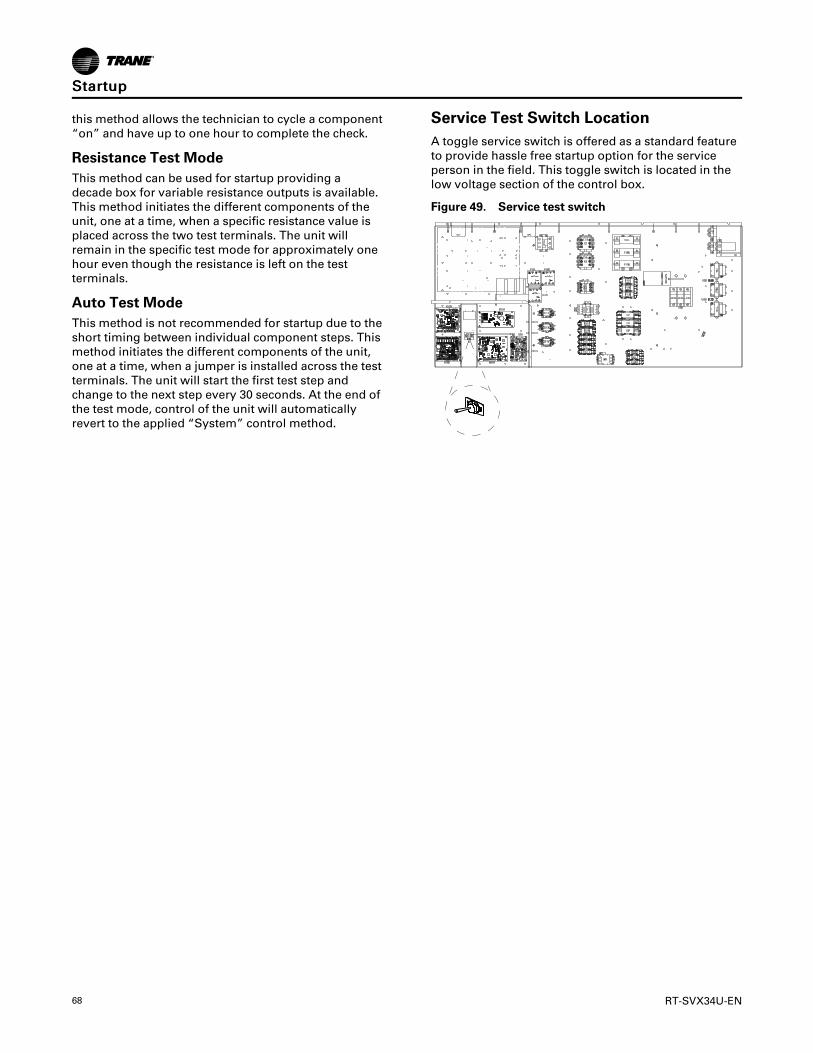
68 RT-SVX34U-EN
this method allows the technician to cycle a component“on” and have up to one hour to complete the check.
Resistance Test ModeThis method can be used for startup providing adecade box for variable resistance outputs is available.This method initiates the different components of theunit, one at a time, when a specific resistance value isplaced across the two test terminals. The unit willremain in the specific test mode for approximately onehour even though the resistance is left on the testterminals.
Auto Test ModeThis method is not recommended for startup due to theshort timing between individual component steps. Thismethod initiates the different components of the unit,one at a time, when a jumper is installed across the testterminals. The unit will start the first test step andchange to the next step every 30 seconds. At the end ofthe test mode, control of the unit will automaticallyrevert to the applied “System” control method.
Service Test Switch LocationA toggle service switch is offered as a standard featureto provide hassle free startup option for the serviceperson in the field. This toggle switch is located in thelow voltage section of the control box.
Figure 49. Service test switch
SSttaarrttuupp

RT-SVX34U-EN 69
Table 41. Test mode states for traditional VAV units with modulating hot gas reheat and staged heat
TESTSTEP MODE FAN
VFDCOM-MAND ECON
COMP1
COMP2
COMP3
HEAT1
HEAT2
PUMP-OUT
COOLVALVE
RE-HEATVALVE
VAVBOX
1VFD
SIGNAL100%
OFF100% (10VDC) CLOSED OFF OFF OFF OFF OFF OFF 100% 0% ON
2VFD
SIGNAL0%
OFF0% (0VDC) CLOSED OFF OFF OFF OFF OFF OFF 100% 0% ON
3 MINVENT ON IN-
CONTROL MIN OFF OFF OFF OFF OFF OFF 100% 0% ON
4ECONTESTOPEN
ON IN-CONTROL OPEN OFF OFF OFF OFF OFF OFF 100% 0% ON
5 COOL 1 ON IN-CONTROL MIN ON OFF OFF OFF OFF IN-
CONTROL 100% 0% ON
6 COOL 2 ON IN-CONTROL MIN ON ON OFF OFF OFF IN-
CONTROL 100% 0% ON
7 COOL 3 ON IN-CONTROL MIN ON ON ON OFF OFF IN-
CONTROL 100% 0% ON
8 REHEAT ON IN-CONTROL MIN ON ON ON OFF OFF IN-
CONTROL 50% 50% ON
9 HEAT 1 ON IN-CONTROL MIN OFF OFF OFF ON OFF OFF 100% 0% ON
10 HEAT 2 ON IN-CONTROL MIN OFF OFF OFF ON ON OFF 100% 0% ON
11 RESET
Notes: 2 and 3 stage standard efficiency units (excluding 40–50T std eff. CV):1. For Traditional VAV units, the VFD Command when “In-Control” will be controlled based on Supply Air Pressure Requirements. For SZ VAV units, the
VFD Command will be at discrete points during Test Mode.2. For 27.5-35Tunits, both compressors will be energized during the Cool 2 Step. For 40-50Tunits, only Compressor 2 will be energized during the Cool
2 Step.3. The Reheat Pumpout relay will be energized any time the Reheat circuit is energized in active Cooling Mode.4. For units with Statitrac installed, the Exhaust Damper will track the Economizer position during Service Test Mode and the Exhaust Fan will be
energized once the Economizer rises above the Exhaust Enable Setpoint.5. Heating will not be energized during Service Test until the 6 minute VAV Box ON timer has expired.
Notes: 5 stage high efficiency units (including 40–50T std eff. CV):1. Compressor 1 is the smaller compressor on the circuit.2. Condenser fans are controlled as defined for normal operation.3. Exhaust fan operates as defined for normal operation based on economizer position.4. When Compressor 1 is energized with either C1, C2, or with both for 30 minutes continuously, C3 will be required to de-energize for 30 seconds.
SSttaarrttuupp

70 RT-SVX34U-EN
Table 42. Test mode states for CV units with modulating hot gas reheat and staged heat
TESTSTEP MODE FAN ECON
COMP1
COMP2
COMP3
HEAT1
HEAT2
PUMP-OUT
COOLVALVE
REHEATVALVE
VAVBOX
1 FAN ON ON MIN OFF OFF OFF OFF OFF OFF 100% 0% ON
2 ECONOMIZER ON OPEN OFF OFF OFF OFF OFF OFF 100% 0% ON
3 COOL 1 ON MIN ON OFF OFF OFF OFF IN-CONTROL 100% 0% ON
4 COOL 2 ON MIN ON ON OFF OFF OFF IN-CONTROL 100% 0% ON
5 COOL 3 ON MIN ON ON ON OFF OFF IN-CONTROL 100% 0% ON
6 REHEAT ON MIN ON ON ON OFF OFF IN-CONTROL 50% 50% ON
7 HEAT 1 ON MIN OFF OFF OFF ON OFF OFF 100% 0% ON
8 HEAT 2 ON MIN OFF OFF OFF ON ON OFF 100% 0% ON
9 RESET
Notes: 2 and 3 stage standard efficiency units (excluding 40–50T std eff. CV):1. For 27.5-35Tunits, both compressors will be energized during the Cool 2 Step. For 40-50Tunits, only Compressor 2 will be energized during the
Cool 2 Step.2. The Reheat Pumpout relay will be energized any time the Reheat circuit is energized in active Cooling Mode.3. For units with Statitrac installed, the Exhaust Damper will track the Economizer position during Service Test Mode and the Exhaust Fan will be
energized once the Economizer rises above the Exhaust Enable Setpoint.4. Heating will not be energized during Service Test until the 6 minute VAV Box ON timer has expired.
Notes: 5 stage high efficiency units (including 40–50T std eff. CV):1. Compressor 1 is the smaller compressor on the circuit.2. Condenser fans are controlled as defined for normal operation.3. Exhaust fan operates as defined for normal operation based on economizer position.4. When Compressor 1 is energized with either C1, C2, or with both for 30 minutes continuously, C3 will be required to de-energize for 30 seconds.
SSttaarrttuupp
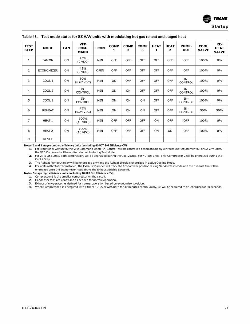
RT-SVX34U-EN 71
Table 43. Test mode states for SZ VAV units with modulating hot gas reheat and staged heat
TESTSTEP MODE FAN
VFDCOM-MAND
ECON COMP1
COMP2
COMP3
HEAT1
HEAT2
PUMP-OUT
COOLVALVE
RE-HEATVALVE
1 FAN ON ON45%(0 VDC) MIN OFF OFF OFF OFF OFF OFF 100% 0%
2 ECONOMIZER ON45%(0 VDC) OPEN OFF OFF OFF OFF OFF OFF 100% 0%
3 COOL 1 ON80%
(6.67 VDC) MIN ON OFF OFF OFF OFF IN-CONTROL 100% 0%
4 COOL 2 ON IN-CONTROL MIN ON ON OFF OFF OFF IN-
CONTROL 100% 0%
5 COOL 3 ON IN-CONTROL MIN ON ON ON OFF OFF IN-
CONTROL 100% 0%
6 REHEAT ON73%
(5.24 VDC) MIN ON ON ON OFF OFF IN-CONTROL 50% 50%
7 HEAT 1 ON100%(10 VDC) MIN OFF OFF OFF ON OFF OFF 100% 0%
8 HEAT 2 ON100%(10 VDC) MIN OFF OFF OFF ON ON OFF 100% 0%
9 RESET
Notes: 2 and 3 stage standard efficiency units (excluding 40-50T Std Efficiency CV):1. For Traditional VAV units, the VFD Command when “In-Control” will be controlled based on Supply Air Pressure Requirements. For SZ VAV units,
the VFD Command will be at discrete points during Test Mode.2. For 27.5-35Tunits, both compressors will be energized during the Cool 2 Step. For 40-50Tunits, only Compressor 2 will be energized during the
Cool 2 Step.3. The Reheat Pumpout relay will be energized any time the Reheat circuit is energized in active Cooling Mode.4. For units with Statitrac installed, the Exhaust Damper will track the Economizer position during Service Test Mode and the Exhaust Fan will be
energized once the Economizer rises above the Exhaust Enable Setpoint.Notes: 5 stage high efficiency units (including 40-50T Std Efficiency CV):
1. Compressor 1 is the smaller compressor on the circuit.2. Condenser fans are controlled as defined for normal operation.3. Exhaust fan operates as defined for normal operation based on economizer position.4. When Compressor 1 is energized with either C1, C2, or with both for 30 minutes continuously, C3 will be required to de-energize for 30 seconds.
SSttaarrttuupp

72 RT-SVX34U-EN
Table 44. Test mode states for traditional VAV units with modulating hot gas reheat and modulating heat
TESTSTEP MODE FAN
VFDCOM-MAND ECON
COMP1
COMP2
COMP3
HEATOUTPUT
PUMP-OUT
COOLVALVE
RE-HEATVALVE
VAVBOX
1VFD
SIGNAL100%
OFF100%(10VDC) CLOSED OFF OFF OFF OFF OFF 100% 0% ON
2VFD
SIGNAL0%
OFF0% (0VDC) CLOSED OFF OFF OFF OFF OFF 100% 0% ON
3 MIN VENT ON IN-CONTROL MIN OFF OFF OFF OFF OFF 100% 0% ON
4ECONTESTOPEN
ON IN-CONTROL OPEN OFF OFF OFF OFF OFF 100% 0% ON
5 COOL 1 ON IN-CONTROL MIN ON OFF OFF OFF IN-
CONTROL 100% 0% ON
6 COOL 2 ON IN-CONTROL MIN ON ON OFF OFF IN-
CONTROL 100% 0% ON
7 COOL 3 ON IN-CONTROL MIN ON ON ON OFF IN-
CONTROL 100% 0% ON
8 REHEAT ON IN-CONTROL MIN ON ON ON OFF IN-
CONTROL 50% 50% ON
9 HEAT 1 ON IN-CONTROL MIN OFF OFF OFF 50% OFF 100% 0% ON
10 HEAT 2 ON IN-CONTROL MIN OFF OFF OFF 100% OFF 100% 0% ON
11 RESET
Notes: 2 and 3 stage standard efficiency units (excluding 40-50T Std Efficiency CV):1. For Traditional VAV units, the VFD Command when “In-Control” will be controlled based on Supply Air Pressure Requirements. For SZ VAV units,
the VFD Command will be at discrete points during Test Mode.2. For 27.5-35Tunits, both compressors will be energized during the Cool 2 Step. For 40-50Tunits, only Compressor 2 will be energized during the
Cool 2 Step.3. The Reheat Pumpout relay will be energized any time the Reheat circuit is energized in active Cooling Mode.4. For units with Statitrac installed, the Exhaust Damper will track the Economizer position during Service Test Mode and the Exhaust Fan will be
energized once the Economizer rises above the Exhaust Enable Setpoint.5. Heating will not be energized during Service Test until the 6 minute VAV Box ON timer has expired.
Notes: 5 stage high efficiency units (including 40-50T Std Efficiency CV):1. Compressor 1 is the smaller compressor on the circuit.2. Condenser fans are controlled as defined for normal operation.3. Exhaust fan operates as defined for normal operation based on economizer position.4. When Compressor 1 is energized with either C1, C2, or with both for 30 minutes continuously, C3 will be required to de-energize for 30 seconds.
SSttaarrttuupp

RT-SVX34U-EN 73
Table 45. Test mode states for CV units with modulating hot gas reheat and modulating heat
TESTSTEP MODE FAN ECON
COMP1
COMP2
COMP3
HEATOUTPUT PUMPOUT
COOLVALVE
REHEATVALVE
VAVBOX
1 FAN ON ON MIN OFF OFF OFF OFF OFF 100% 0% ON
2 ECONOMIZER ON OPEN OFF OFF OFF OFF OFF 100% 0% ON
3 COOL 1 ON MIN ON OFF OFF OFF IN-CONTROL 100% 0% ON
4 COOL 2 ON MIN ON ON OFF OFF IN-CONTROL 100% 0% ON
5 COOL 3 ON MIN ON ON ON OFF IN-CONTROL 100% 0% ON
6 REHEAT ON MIN ON ON ON OFF IN-CONTROL 50% 50% ON
7 HEAT 1 ON MIN OFF OFF OFF 50% OFF 100% 0% ON
8 HEAT 2 ON MIN OFF OFF OFF 100% OFF 100% 0% ON
9 RESET
Notes: 2 and 3 stage standard efficiency units (excluding 40-50T Std Efficiency CV):1. For 27.5-35Tunits, both compressors will be energized during the Cool 2 Step. For 40-50Tunits, only Compressor 2 will be energized during the
Cool 2 Step.2. The Reheat Pumpout relay will be energized any time the Reheat circuit is energized in active Cooling Mode.3. For units with Statitrac installed, the Exhaust Damper will track the Economizer position during Service Test Mode and the Exhaust Fan will be
energized once the Economizer rises above the Exhaust Enable Setpoint.4. Heating will not be energized during Service Test until the 6 minute VAV Box ON timer has expired.
Notes: 5 stage high efficiency units (including 40-50T Std Efficiency CV):1. Compressor 1 is the smaller compressor on the circuit.2. Condenser fans are controlled as defined for normal operation.3. Exhaust fan operates as defined for normal operation based on economizer position.4. When Compressor 1 is energized with either C1, C2, or with both for 30 minutes continuously, C3 will be required to de-energize for 30 seconds.
SSttaarrttuupp
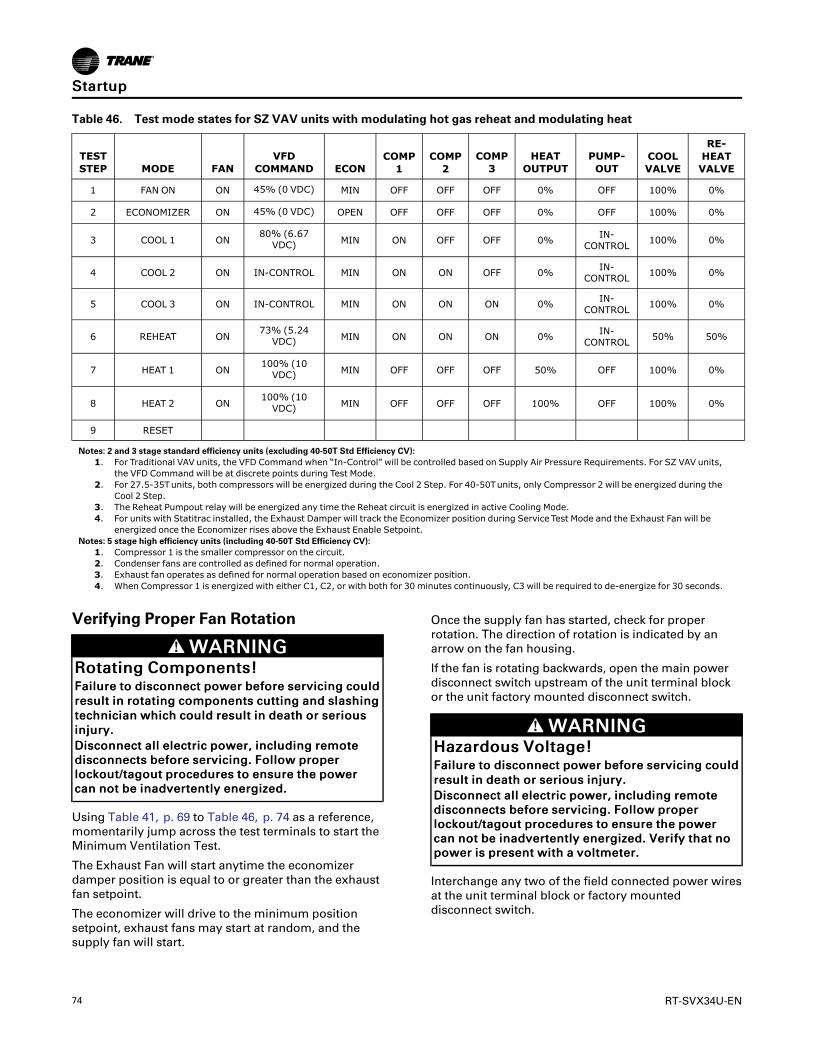
74 RT-SVX34U-EN
Table 46. Test mode states for SZ VAV units with modulating hot gas reheat and modulating heat
TESTSTEP MODE FAN
VFDCOMMAND ECON
COMP1
COMP2
COMP3
HEATOUTPUT
PUMP-OUT
COOLVALVE
RE-HEATVALVE
1 FAN ON ON 45% (0 VDC) MIN OFF OFF OFF 0% OFF 100% 0%
2 ECONOMIZER ON 45% (0 VDC) OPEN OFF OFF OFF 0% OFF 100% 0%
3 COOL 1 ON80% (6.67VDC) MIN ON OFF OFF 0% IN-
CONTROL 100% 0%
4 COOL 2 ON IN-CONTROL MIN ON ON OFF 0% IN-CONTROL 100% 0%
5 COOL 3 ON IN-CONTROL MIN ON ON ON 0% IN-CONTROL 100% 0%
6 REHEAT ON73% (5.24VDC) MIN ON ON ON 0% IN-
CONTROL 50% 50%
7 HEAT 1 ON100% (10VDC) MIN OFF OFF OFF 50% OFF 100% 0%
8 HEAT 2 ON100% (10VDC) MIN OFF OFF OFF 100% OFF 100% 0%
9 RESET
Notes: 2 and 3 stage standard efficiency units (excluding 40-50T Std Efficiency CV):1. For Traditional VAV units, the VFD Command when “In-Control” will be controlled based on Supply Air Pressure Requirements. For SZ VAV units,
the VFD Command will be at discrete points during Test Mode.2. For 27.5-35Tunits, both compressors will be energized during the Cool 2 Step. For 40-50Tunits, only Compressor 2 will be energized during the
Cool 2 Step.3. The Reheat Pumpout relay will be energized any time the Reheat circuit is energized in active Cooling Mode.4. For units with Statitrac installed, the Exhaust Damper will track the Economizer position during Service Test Mode and the Exhaust Fan will be
energized once the Economizer rises above the Exhaust Enable Setpoint.Notes: 5 stage high efficiency units (including 40-50T Std Efficiency CV):
1. Compressor 1 is the smaller compressor on the circuit.2. Condenser fans are controlled as defined for normal operation.3. Exhaust fan operates as defined for normal operation based on economizer position.4. When Compressor 1 is energized with either C1, C2, or with both for 30 minutes continuously, C3 will be required to de-energize for 30 seconds.
Verifying Proper Fan Rotation
WWAARRNNIINNGGRRoottaattiinngg CCoommppoonneennttss!!FFaaiilluurree ttoo ddiissccoonnnneecctt ppoowweerr bbeeffoorree sseerrvviicciinngg ccoouullddrreessuulltt iinn rroottaattiinngg ccoommppoonneennttss ccuuttttiinngg aanndd ssllaasshhiinnggtteecchhnniicciiaann wwhhiicchh ccoouulldd rreessuulltt iinn ddeeaatthh oorr sseerriioouussiinnjjuurryy..DDiissccoonnnneecctt aallll eelleeccttrriicc ppoowweerr,, iinncclluuddiinngg rreemmootteeddiissccoonnnneeccttss bbeeffoorree sseerrvviicciinngg.. FFoollllooww pprrooppeerrlloocckkoouutt//ttaaggoouutt pprroocceedduurreess ttoo eennssuurree tthhee ppoowweerrccaann nnoott bbee iinnaaddvveerrtteennttllyy eenneerrggiizzeedd..
Using Table 41, p. 69 to Table 46, p. 74 as a reference,momentarily jump across the test terminals to start theMinimum Ventilation Test.
The Exhaust Fan will start anytime the economizerdamper position is equal to or greater than the exhaustfan setpoint.
The economizer will drive to the minimum positionsetpoint, exhaust fans may start at random, and thesupply fan will start.
Once the supply fan has started, check for properrotation. The direction of rotation is indicated by anarrow on the fan housing.
If the fan is rotating backwards, open the main powerdisconnect switch upstream of the unit terminal blockor the unit factory mounted disconnect switch.
WWAARRNNIINNGGHHaazzaarrddoouuss VVoollttaaggee!!FFaaiilluurree ttoo ddiissccoonnnneecctt ppoowweerr bbeeffoorree sseerrvviicciinngg ccoouullddrreessuulltt iinn ddeeaatthh oorr sseerriioouuss iinnjjuurryy..DDiissccoonnnneecctt aallll eelleeccttrriicc ppoowweerr,, iinncclluuddiinngg rreemmootteeddiissccoonnnneeccttss bbeeffoorree sseerrvviicciinngg.. FFoollllooww pprrooppeerrlloocckkoouutt//ttaaggoouutt pprroocceedduurreess ttoo eennssuurree tthhee ppoowweerrccaann nnoott bbee iinnaaddvveerrtteennttllyy eenneerrggiizzeedd.. VVeerriiffyy tthhaatt nnooppoowweerr iiss pprreesseenntt wwiitthh aa vvoollttmmeetteerr..
Interchange any two of the field connected power wiresat the unit terminal block or factory mounteddisconnect switch.
SSttaarrttuupp
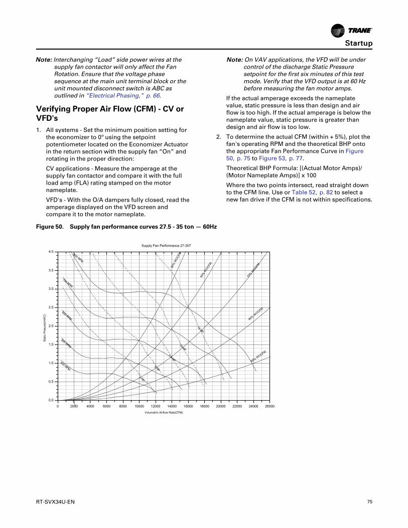
RT-SVX34U-EN 75
NNoottee:: Interchanging “Load” side power wires at thesupply fan contactor will only affect the FanRotation. Ensure that the voltage phasesequence at the main unit terminal block or theunit mounted disconnect switch is ABC asoutlined in “Electrical Phasing,” p. 66.
Verifying Proper Air Flow (CFM) - CV orVFD's1. All systems - Set the minimum position setting for
the economizer to 0º using the setpointpotentiometer located on the Economizer Actuatorin the return section with the supply fan “On” androtating in the proper direction:
CV applications - Measure the amperage at thesupply fan contactor and compare it with the fullload amp (FLA) rating stamped on the motornameplate.
VFD's - With the O/A dampers fully closed, read theamperage displayed on the VFD screen andcompare it to the motor nameplate.
NNoottee:: On VAV applications, the VFD will be undercontrol of the discharge Static Pressuresetpoint for the first six minutes of this testmode. Verify that the VFD output is at 60 Hzbefore measuring the fan motor amps.
If the actual amperage exceeds the nameplatevalue, static pressure is less than design and airflow is too high. If the actual amperage is below thenameplate value, static pressure is greater thandesign and air flow is too low.
2. To determine the actual CFM (within + 5%), plot thefan's operating RPM and the theoretical BHP ontothe appropriate Fan Performance Curve in Figure50, p. 75 to Figure 53, p. 77.
Theoretical BHP Formula: [(Actual Motor Amps)/(Motor Nameplate Amps)] x 100
Where the two points intersect, read straight downto the CFM line. Use or Table 52, p. 82 to select anew fan drive if the CFM is not within specifications.
Figure 50. Supply fan performance curves 27.5 - 35 ton — 60Hz
SSttaarrttuupp

76 RT-SVX34U-EN
Figure 51. Supply fan performance curves 40 and 50 ton — 60Hz
Figure 52. Supply fan performance — 22.9-29.2 tons — 50Hz
0 2000 4000 6000 8000 10000 12000 14000 16000 18000 20000 22000 24000 26000
0.0
0.5
1.0
1.5
2.0
2.5
3.0
3.5
4.0
(0.0)
(125)
(249)
(374)
(498)
(623)
(747)
(872)
(996)
L/S in 1000's(0) (.94) (1.89) (2.83) (3.78) (4.72) (5.66) (6.61) (7.55) (8.5) (9.44) (10.38) (11.33) (12.27)
Supply Fan Performance
90% W
OCFM
80% W
OCFM
70%
WOCF
M
60%
WOC
FM50%
WO
CFM
15 HP
10 HP
7.5 HP
5 HP
3 HP
800 RPM
700 RPM
600 RPM
500 RPM
400 RPM
Volumetric Airflow Rate(CFM)
Stat
ic P
resu
re(In
WC
)
SSttaarrttuupp
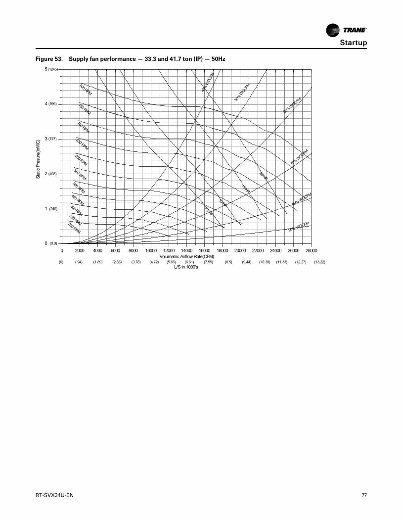
RT-SVX34U-EN 77
Figure 53. Supply fan performance — 33.3 and 41.7 ton (IP) — 50Hz
0 2000 4000 6000 8000 10000 12000 14000 16000 18000 20000 22000 24000 26000 28000
0
1
2
3
4
5(1245)
(0.0)
(249)
(498)
(747)
(996)
L/S in 1000's(0) (.94) (1.89) (2.83) (3.78) (4.72) (5.66) (6.61) (7.55) (8.5) (9.44) (10.38) (11.33) (12.27) (13.22)
90% WOCFM
80% WOCFM
70% W
OCFM
60% W
OCFM50%
WOCF
M
40%
WO
CFM
20 HP
15 HP
10 HP7.5 HP
800 RPM
750 RPM
700 RPM
650 RPM
600 RPM
550 RPM500 RPM
450 RPM400 RPM350 RPM300 RPM
Volumetric Airflow Rate(CFM)
Stat
ic P
resu
re(In
WC
)SSttaarrttuupp

78 RT-SVX34U-EN
Table 47. TC*/YC*300–600 MBH economizer (R/A)damper pressure drop – 60Hz
Unit Capacity Airflow (CFM) Pressure Drop (iwc)
8000 0.035
8500 0.038
9000 0.042
9500 0.046
10000 0.051
10500 0.056
11000 0.061
11500 0.067
12000 0.073
12500 0.080
30
9000 0.042
9500 0.046
10000 0.051
10500 0.056
11000 0.061
11500 0.067
12000 0.073
12500 0.080
13000 0.087
35
10000 0.051
10500 0.056
11000 0.061
11500 0.067
12000 0.073
12500 0.095
14000 0.103
14500 0.111
Table 47. TC*/YC*300–600 MBH economizer (R/A)damper pressure drop – 60Hz (continued)
Unit Capacity Airflow (CFM) Pressure Drop (iwc)
40
12000 0.072
12500 0.075
13000 0.079
13500 0.083
14000 0.087
14500 0.092
15000 0.098
15500 0.104
16000 0.110
16500 0.117
17000 0.124
17500 0.132
18000 0.140
50
15000 0.098
15500 0.104
16000 0.110
16500 0.117
17000 0.124
17500 0.132
18000 0.140
18500 0.149
19000 0.159
19500 0.168
20000 0.179Notes:
1. Static pressure drops for the return air damper must beadded to the system external static pressure as anaccessory when using the fan performance tables and thefan curves to determine actual fan performance.
2. Pressure drops are listed in inches of water column.
SSttaarrttuupp

RT-SVX34U-EN 79
Table 48. Supply air fan drive selections — 60 Hz
Nominal Tons7.5 HP 10 HP 15 HP 20 HP
RPM Drive No. RPM Drive No. RPM Drive No. RPM Drive No.
27.5
550 A
600 B
650 C
700 D
750(a) E
30
550
600
650
700 D
750 E 750 E
790(b) F
800(a) G
35
600 B
650 C
700 D
750 E 750 E
790(b) F
800(a) G
40
500 H
525 J
575 K
625 L
675 M
725 N
50
525 J
575 K
625 L
675 M 675 M
725 N
(a) For YC gas heat units only.(b) For TC/TE Cooling only and Electric Heat units only.
SSttaarrttuupp

80 RT-SVX34U-EN
Table 49. Component static pressure drops (in. W.G.) — 60Hz
Nom.Tons
CFMStd Air
Heating SystemStandardEfficiencyID Coil
HighEfficiencyID Coil
Filters
Econo-mizer
Hot GasReheatCoil
Gas Heat Electric HeatThrow-away MERV 8 High Eff
MERV14 HighEff
Low High1Ele-ment
2Ele-ments
Dry Wet Dry Wet 2" 2" 4" 4"
27.5
8000 0.08 0.06 0.05 0.06 0.12 0.19 0.16 0.25 0.08 0.12 0.11 0.33 0.04 0.089000 0.10 0.08 0.07 0.07 0.14 0.22 0.19 0.29 0.09 0.14 0.13 0.39 0.04 0.1010000 0.13 0.10 0.08 0.09 0.17 0.26 0.23 0.34 0.10 0.16 0.15 0.45 0.05 0.1211000 0.15 0.12 0.10 0.11 0.20 0.30 0.27 0.39 0.12 0.20 0.17 0.52 0.06 0.1412000 0.18 0.14 0.12 0.13 0.23 0.34 0.31 0.45 0.13 0.21 0.20 0.59 0.07 0.17
30
9000 0.10 0.08 0.07 0.07 0.14 0.22 0.19 0.29 0.09 0.14 0.13 0.39 0.04 0.1010000 0.13 0.10 0.08 0.09 0.17 0.26 0.23 0.34 0.10 0.16 0.15 0.45 0.05 0.1211000 0.15 0.12 0.10 0.11 0.20 0.30 0.27 0.39 0.12 0.20 0.17 0.52 0.06 0.1412000 0.18 0.14 0.12 0.13 0.23 0.34 0.31 0.45 0.14 0.23 0.21 0.59 0.07 0.1713000 0.21 0.16 0.14 0.15 0.27 0.38 0.35 0.50 0.15 0.26 0.23 0.66 0.09 0.20
35
10500 0.14 0.11 0.09 0.1 0.25 0.37 0.25 0.37 0.11 0.18 0.16 0.48 0.06 0.1311500 0.17 0.13 0.11 0.12 0.29 0.42 0.29 0.42 0.13 0.21 0.19 0.55 0.07 0.1612500 0.20 0.15 0.13 0.14 0.33 0.48 0.33 0.48 0.14 0.24 0.21 0.62 0.08 0.1813500 0.23 0.18 0.15 0.16 0.38 0.53 0.38 0.53 0.15 0.26 0.23 0.70 0.10 0.2214500 0.26 0.20 0.18 0.19 0.42 0.59 0.42 0.59 0.17 0.30 0.27 0.77 0.11 0.25
40
12000 0.01 0.03 0.08 0.13 0.24 0.36 0.30 0.45 0.10 0.19 0.17 0.48 0.07 0.0613000 0.01 0.04 0.10 0.15 0.28 0.41 0.35 0.51 0.12 0.23 0.20 0.53 0.08 0.0714000 0.02 0.05 0.11 0.18 0.31 0.46 0.39 0.57 0.13 0.25 0.22 0.59 0.09 0.0815000 0.02 0.05 0.13 0.20 0.35 0.50 0.44 0.63 0.14 0.28 0.24 0.66 0.10 0.0916000 0.02 0.06 0.15 0.23 0.39 0.55 0.49 0.69 0.15 0.31 0.27 0.72 0.11 0.1017000 0.02 0.07 0.17 0.26 0.43 0.60 0.54 0.75 0.17 0.35 0.30 0.79 0.12 0.11
50
15000 0.02 0.05 0.13 0.2 0.44 0.63 0.44 0.63 0.14 0.28 0.24 0.66 0.1 0.0916000 0.02 0.06 0.15 0.23 0.49 0.69 0.49 0.69 0.15 0.31 0.27 0.72 0.11 0.1017000 0.02 0.07 0.17 0.26 0.54 0.75 0.54 0.75 0.17 0.35 0.30 0.79 0.12 0.1118000 0.03 0.08 0.19 0.29 0.59 0.82 0.59 0.82 0.18 0.38 0.33 0.85 0.14 0.1319000 0.03 0.08 0.21 0.32 0.65 0.89 0.65 0.89 0.19 0.42 0.35 0.92 0.16 0.1420000 0.03 0.09 0.23 0.36 0.71 0.96 0.71 0.96 0.20 0.45 0.38 0.99 0.18 0.16
Note: Static pressure drops of accessory components must be added to external static pressure to enter fan selection tables.
Table 50. Component static pressure drops in. W.G (I-P) — 50Hz
Nom.Tons
CFMStd Air
Heating SystemStandardEfficiencyID Coil
HighEfficiencyID Coil
Filters
Econo-mizer
Hot GasReheatCoil
Gas Heat Electric HeatThrow-away MERV 8 High Eff
MERV14 HighEff
Low High1Ele-ment
2Ele-ments
Dry Wet Dry Wet 2" 2" 4" 4"
23 (80)
6670 0.07 0.05 0.04 0.05 0.09 0.14 0.12 0.19 0.05 0.08 0.07 0.20 0.331 0.057500 0.08 0.07 0.06 0.06 0.11 0.17 0.14 0.23 0.07 0.11 0.10 0.24 0.040 0.078330 0.10 0.08 0.07 0.08 0.13 0.20 0.17 0.26 0.08 0.13 0.12 0.28 0.049 0.089170 0.13 0.10 0.08 0.09 0.15 0.23 0.20 0.30 0.09 0.15 0.14 0.32 0.059 0.1010000 0.15 0.12 0.10 0.11 0.17 0.26 0.23 0.34 0.11 0.18 0.16 0.37 0.070 0.12
25 (88)
7500 0.08 0.07 0.06 0.06 0.11 0.17 0.14 0.23 0.07 0.11 0.10 0.24 0.04 0.078330 0.10 0.08 0.07 0.08 0.13 0.20 0.17 0.26 0.08 0.13 0.12 0.28 0.049 0.089170 0.13 0.10 0.08 0.09 0.15 0.23 0.20 0.30 0.09 0.15 0.14 0.32 0.059 0.1010000 0.15 0.12 0.10 0.11 0.17 0.26 0.23 0.34 0.11 0.18 0.17 0.37 0.070 0.12
29(103)
8750 0.11 0.09 0.08 0.08 0.18 0.28 0.18 0.28 0.09 0.15 0.13 0.30 0.054 0.099580 0.14 0.11 0.09 0.10 0.21 0.32 0.21 0.32 0.10 0.17 0.16 0.34 0.065 0.1111200 0.19 0.15 0.13 0.14 0.28 0.41 0.28 0.41 0.12 0.21 0.19 0.43 0.077 0.1512100 0.22 0.17 0.15 0.16 0.31 0.46 0.31 0.46 0.13 0.22 0.21 0.48 0.091 0.17
SSttaarrttuupp

RT-SVX34U-EN 81
Table 50. Component static pressure drops in. W.G (I-P) — 50Hz (continued)
Nom.Tons
CFMStd Air
Heating SystemStandardEfficiencyID Coil
HighEfficiencyID Coil
Filters
Econo-mizer
Hot GasReheatCoil
Gas Heat Electric HeatThrow-away MERV 8 High Eff
MERV14 HighEff
Low High1Ele-ment
2Ele-ments
Dry Wet Dry Wet 2" 2" 4" 4"
33(118)
10000 0.01 0.03 0.07 0.11 0.18 0.28 0.22 0.35 0.11 0.18 0.16 0.37 0.070 0.0410800 0.01 0.03 0.08 0.13 0.20 0.31 0.25 0.39 0.12 0.21 0.18 0.41 0.076 0.0511700 0.01 0.04 0.10 0.15 0.23 0.35 0.29 0.44 0.13 0.23 0.20 0.46 0.085 0.0512500 0.01 0.04 0.11 0.17 0.26 0.39 0.32 0.48 0.14 0.26 0.23 0.50 0.096 0.0613300 0.02 0.05 0.12 0.19 0.29 0.42 0.36 0.53 0.15 0.28 0.25 0.55 0.107 0.0714200 0.02 0.06 0.14 0.22 0.32 0.46 0.40 0.58 0.17 0.32 0.28 0.61 0.120 0.08
42(146)
12500 0.01 0.04 0.11 0.17 0.33 0.48 0.33 0.48 0.14 0.26 0.23 0.50 0.095 0.0613300 0.02 0.05 0.12 0.19 0.36 0.53 0.36 0.53 0.15 0.28 0.25 0.55 0.108 0.0714200 0.02 0.06 0.16 0.24 0.40 0.58 0.40 0.58 0.17 0.34 0.29 0.61 0.120 0.0815800 0.02 0.07 0.18 0.27 0.48 0.68 0.48 0.68 0.19 0.38 0.34 0.71 0.136 0.1016700 0.03 0.08 0.20 0.30 0.53 0.74 0.53 0.74 0.20 0.41 0.36 0.77 0.155 0.11
Note: Static pressure drops of accessory components must be added to external static pressure to enter fan performance tables.
Table 51. Component static pressure drops Pa (SI) — 50 Hz
Nom.Std Tons(kW)
L/s StdAir
Heating System StandardEfficiency ID
Coil
Filters
EconomizerGas Heat Electric Heat
Throw-away MERV 8 High Eff MERV 14
High Eff
Low High 1Element
2Elements
Dry Wet Adder 50mm 100mm 100mm
80 (23)
3150 17 13 11 12 21 34 12 19 17 38 8
3540 21 16 14 15 26 41 17 26 24 45 10
3930 26 20 17 19 30 48 19 31 29 50 12
4320 31 24 21 23 36 55 22 36 34 57 15
4720 37 29 25 27 41 62 26 43 38 65 17
88 (25)
3540 21 16 14 15 26 41 17 26 24 45 10
3930 26 20 17 19 30 48 19 31 29 50 12
4320 31 24 21 23 36 55 22 36 34 57 15
5120 44 34 29 32 41 62 26 43 41 67 17
103 (29)
4130 29 22 19 21 44 68 22 36 31 55 13
4520 34 27 23 25 51 78 24 41 38 62 16
4920 41 32 27 29 66 97 29 50 46 77 19
5310 47 37 32 34 75 109 31 53 50 86 23
118 (33)
4720 2 7 18 27 43 67 26 43 38 65 17
5120 3 8 21 32 49 75 29 50 43 69 19
5510 3 10 24 37 56 84 31 55 48 77 21
5900 4 11 27 42 62 92 34 62 55 84 24
6290 4 12 31 48 69 101 36 67 60 88 27
6680 5 14 35 54 77 111 41 77 67 98 30
SSttaarrttuupp

82 RT-SVX34U-EN
Table 51. Component static pressure drops Pa (SI) — 50 Hz (continued)
Nom.Std Tons(kW)
L/s StdAir
Heating System StandardEfficiency ID
Coil
Filters
EconomizerGas Heat Electric Heat
Throw-away MERV 8 High Eff MERV 14
High Eff
Low High 1Element
2Elements
Dry Wet Adder 50mm 100mm 100mm
146 (42)
5900 4 11 27 42 78 115 34 62 55 84 24
6290 4 12 31 48 86 126 36 67 60 88 27
6680 5 14 35 54 96 139 41 82 72 100 30
7070 5 16 39 60 115 162 46 91 82 112 34
7470 6 18 44 67 126 176 48 98 86 124 39
Note: Static pressure drops of accessory components must be added to external static pressure to enter fan selection tables.
Table 52. Supply air fan drive selections — 50 Hz
Nominal Tons(kW)
7.5 hp (5.6 kW) 10 hp (7.5 kW) 15 hp (10 kW) 20 hp (15 kW)
rpm Drive No rpm Drive No rpm Drive No rpm Drive No
23 (80)
458 A — — — — — —
500 B — — — — — —
541 C — — — — — —
583 — 583 D — — — —
625 — 625(a) E — — — —
25 (88)
458 A — — — — — —
500 B — — — — — —
541 C — — — — — —
583 — 583 D — — — —
625 — 625 E — — — —
29 (103)
500 B — — — — — —
541 — 541 C — — — —
583 — 583 D — — — —
658 — — — 658(b) F — —
664 — — — 664(a) G — —
33 (118)
417 — 417 H — — — —
437 — 437 J — — — —
479 — 479 K — — — —
521 — — — 521 L — —
562 — — — 562 M — —
604 — — — 604 N — —
42 (146)
437 — 437 J — — — —
479 — 479 K — — — —
521 — — — 521 L — —
562 — — — 562 M — —
604 — — — — — 604 N
(a) For YC gas/electric only.(b) For TC and TE Cooling only and with electric Heat units only.
SSttaarrttuupp

RT-SVX34U-EN 83
Exhaust Fan OperationTo start the optional power exhaust fans, use theeconomizer test procedures in Table 41, p. 69 - Table46, p. 74 to drive the economizer dampers to the openposition. The exhaust fans will start when the damperposition is equal to or greater than the exhaust fansetpoint. If optional power exhaust is selected, anaccess door must be field-installed on the horizontalreturn ductwork to provide access to exhaust fanmotors.
The exhaust fan will start anytime the economizerdamper position is equal to or greater than the exhaustfan setpoint.
WWAARRNNIINNGGRRoottaattiinngg CCoommppoonneennttss!!FFaaiilluurree ttoo ddiissccoonnnneecctt ppoowweerr bbeeffoorree sseerrvviicciinngg ccoouullddrreessuulltt iinn rroottaattiinngg ccoommppoonneennttss ccuuttttiinngg aanndd ssllaasshhiinnggtteecchhnniicciiaann wwhhiicchh ccoouulldd rreessuulltt iinn ddeeaatthh oorr sseerriioouussiinnjjuurryy..DDiissccoonnnneecctt aallll eelleeccttrriicc ppoowweerr,, iinncclluuddiinngg rreemmootteeddiissccoonnnneeccttss bbeeffoorree sseerrvviicciinngg.. FFoollllooww pprrooppeerrlloocckkoouutt//ttaaggoouutt pprroocceedduurreess ttoo eennssuurree tthhee ppoowweerrccaann nnoott bbee iinnaaddvveerrtteennttllyy eenneerrggiizzeedd..
Verify that the fans are operating properly and the CFMis within the job specifications. Refer to power exhaustfan performance tables beginning with Table 53, p. 83for the exhaust fan performance characteristics.
Available power adjustments:
• The power exhaust fan(s) comes on based on theposition of the of the exhaust fan setpointpotentiometer on the RTOM (Reliatel OptionsModule). The setpoint is factory set at 25%. Theexhaust fan(s) will come on anytime theeconomizer damper position is equal to or greaterthan the active exhaust fan setpoint.
• Physical damper blade stops limit the amount ofexhaust airflow by limiting the maximum openingof the damper blades. These stops (sliding bracketssecured with wing-nuts) are present under the rainhood on the non-modulating power exhaust option.There is one stop on each side of each damper. Thepractical range of blade position control is between1.5" and 4.0" blade opening. The damper is wide-open at 4.0". The stops on each side of a dampermust be in the same position, such that the damperblade connecting member contacts the stops at thesame time.
• The modulating power exhaust actuator tracks theposition of the economizer damper actuator suchthat the power exhaust dampers proportionallyfollow or track the fresh air damper position.
• When the Statitrac option is selected, the exhaustactuator will operate independently of theeconomizer in order to relieve positive buildingpressure. If a Space Pressure Transducer failure
occurs, the unit will revert back to fresh air trackingcontrol.
• The proportional offset between the dampers isadjustable. With direct-drive ultra-low-leak exhaustoptions, actuator stroke can be adjusted asdescribed in “Economizer (O/A) Dampers,” p. 84.The stroke limit can be set between 33% and 100%of full stroke.
NNoottee:: The barometric damper continues to function asa pressure relief damper up to the maximumstop position.
To adjust the damper blade stops, refer to figureFigure 54, p. 84 to Figure 57, p. 84.
If the fan speed needs to be changed from the currentoperating speed, refer to the unit wiring diagram andthe XTB1 and XTB2 terminal strip located in theeconomizer section.
Table 53. Power exhaust fan performance— 27.5-35Ton — 60 Hz
ReturnDuct Static(in. wc)
Power Exhaust Selection
50% (min) 100% (max)
Damper Blade Open Distance (in.)
(min) (max) (min) (max)
CFM
0.0 3812 6866 7624 13742
0.1 3497 5296 6995 10591
0.2 3190 4458 6325 9000
0.3 2884 3812 5768 7635
0.4 2621 3359 5241 6719
0.5 2342 2885 4683 5771
Table 54. Power exhaust fan performance — 40-50Ton — 60 Hz
Return DuctStatic (in.wc)
Power Exhaust Selection
50% (min) 100% (max)
Damper Blade Open Distance (in.)
(min) (max) (min) (max)
CFM
0.0 4854 8035 9708 16069
0.1 4575 7410 9151 14820
0.2 4262 6450 8552 13496
0.3 4011 6027 8021 12054
0.4 3718 5526 7436 11051
0.5 3467 5186 6933 10373
SSttaarrttuupp

84 RT-SVX34U-EN
Table 55. Power exhaust fan performance — 22.9 -29.2 Ton — 50 Hz
ReturnDuct Static
(Pa)
Power Exhaust Selection
50% (min) 100% (max)
Damper Blade Open Distance (mm)
(min) (max) (min) (max)
L/s
0.0 1499 2701 2999 5405
24.9 1375 2083 2751 4166
49.8 1255 1753 2488 3540
74.7 1134 1499 2269 3003
99.6 1031 1321 2061 2643
124.5 921 1135 1842 2270
Table 56. Power exhaust fan performance — 33.3 -41.7 Ton — 50 Hz
Return DuctStatic (Pa)
Power Exhaust Selection
50% (min) 100% (max)
Damper Blade Open Distance(mm)
(min) (max) (min) (max)
L/s
0.0 1909 3160 3818 6321
24.9 1800 2915 3599 5829
49.8 1676 2537 3364 5308
74.7 1577 2371 3155 4741
99.6 1462 2173 2925 4347
124.5 1364 2040 2727 4080
Figure 54. (Upflow) Exhaust damper actuatoradjustment
Damper Actuator Adjustment
Figure 55. (Horizontal) Exhaust damper actuatoradjustment
Damper ActuatorAdjustment
Figure 56. (Upflow) Exhaust maximum damperposition
Less Exhaust
More Exhaust
Figure 57. (Horizontal) Exhaust maximum damperposition
Less Exhaust
More Exhaust
Economizer Damper AdjustmentEconomizer (O/A) DampersArbitrarily adjusting the outside air dampers to openfully when the return air dampers are fully closed canoverload the supply fan motor or deliver higher CFM tothe space than designed. This causes higher operating
SSttaarrttuupp
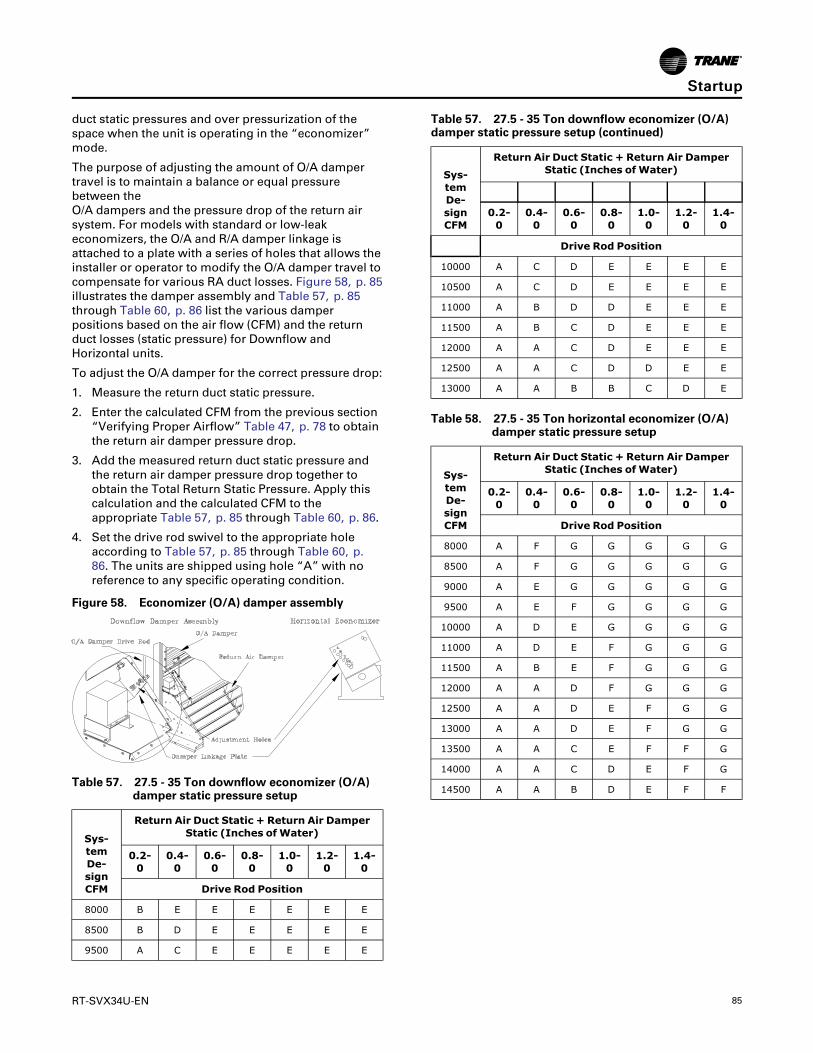
RT-SVX34U-EN 85
duct static pressures and over pressurization of thespace when the unit is operating in the “economizer”mode.
The purpose of adjusting the amount of O/A dampertravel is to maintain a balance or equal pressurebetween theO/A dampers and the pressure drop of the return airsystem. For models with standard or low-leakeconomizers, the O/A and R/A damper linkage isattached to a plate with a series of holes that allows theinstaller or operator to modify the O/A damper travel tocompensate for various RA duct losses. Figure 58, p. 85illustrates the damper assembly and Table 57, p. 85through Table 60, p. 86 list the various damperpositions based on the air flow (CFM) and the returnduct losses (static pressure) for Downflow andHorizontal units.
To adjust the O/A damper for the correct pressure drop:
1. Measure the return duct static pressure.
2. Enter the calculated CFM from the previous section“Verifying Proper Airflow” Table 47, p. 78 to obtainthe return air damper pressure drop.
3. Add the measured return duct static pressure andthe return air damper pressure drop together toobtain the Total Return Static Pressure. Apply thiscalculation and the calculated CFM to theappropriate Table 57, p. 85 through Table 60, p. 86.
4. Set the drive rod swivel to the appropriate holeaccording to Table 57, p. 85 through Table 60, p.86. The units are shipped using hole “A” with noreference to any specific operating condition.
Figure 58. Economizer (O/A) damper assembly
Table 57. 27.5 - 35 Ton downflow economizer (O/A)damper static pressure setup
Sys-temDe-signCFM
Return Air Duct Static + Return Air DamperStatic (Inches ofWater)
0.2-0
0.4-0
0.6-0
0.8-0
1.0-0
1.2-0
1.4-0
Drive Rod Position
8000 B E E E E E E
8500 B D E E E E E
9500 A C E E E E E
Table 57. 27.5 - 35 Ton downflow economizer (O/A)damper static pressure setup (continued)
Sys-temDe-signCFM
Return Air Duct Static + Return Air DamperStatic (Inches ofWater)
0.2-0
0.4-0
0.6-0
0.8-0
1.0-0
1.2-0
1.4-0
Drive Rod Position
10000 A C D E E E E
10500 A C D E E E E
11000 A B D D E E E
11500 A B C D E E E
12000 A A C D E E E
12500 A A C D D E E
13000 A A B B C D E
Table 58. 27.5 - 35 Ton horizontal economizer (O/A)damper static pressure setup
Sys-temDe-signCFM
Return Air Duct Static + Return Air DamperStatic (Inches ofWater)
0.2-0
0.4-0
0.6-0
0.8-0
1.0-0
1.2-0
1.4-0
Drive Rod Position
8000 A F G G G G G
8500 A F G G G G G
9000 A E G G G G G
9500 A E F G G G G
10000 A D E G G G G
11000 A D E F G G G
11500 A B E F G G G
12000 A A D F G G G
12500 A A D E F G G
13000 A A D E F G G
13500 A A C E F F G
14000 A A C D E F G
14500 A A B D E F F
SSttaarrttuupp

86 RT-SVX34U-EN
Table 59. 40 - 50 Ton downflow economizer (O/A)damper static pressure setup
Sys-temDe-signCFM
Return Air Duct Static + Return Air DamperStatic (Inches ofWater)
0.2-0
0.4-0
0.6-0
0.8-0
1.0-0
1.2-0
1.4-0
Drive Rod Position
12000 A A C D E E E
12500 A A C D D E E
13000 A A B C D E E
13500 A A B C D D E
14000 A A B C C D E
14500 A A B B C D D
15000 A A A B C D D
15500 A A A B C D D
16000 A A A B C C D
16500 A A A B B C D
17000 A A A B B C C
17500 A A A A B C C
18000 A A A A B C C
18500 A A A A B B C
19000 A A A A B B C
19500 A A A A B B B
20000 A A A A A B B
Table 60. 40 - 50 Ton horizontal economizer (O/A)damper static pressure setup
Sys-temDe-signCFM
Return Air Duct Static + Return Air DamperStatic (Inches ofWater)
0.2-0
0.4-0
0.6-0
0.8-0
1.0-0
1.2-0
1.4-0
Drive Rod Position
12000 A B E F G G G
12500 A B D E F G G
13000 A A D E F G G
13500 A A D E F G G
14000 A A C E F F G
14500 A A C D E F F
15000 A A B D E F F
15500 A A B D E E F
16000 A A A C D E F
16500 A A A C D E F
17000 A A A B D E E
17500 A A A B D E E
Table 60. 40 - 50 Ton horizontal economizer (O/A)damper static pressure setup (continued)
Sys-temDe-signCFM
Return Air Duct Static + Return Air DamperStatic (Inches ofWater)
0.2-0
0.4-0
0.6-0
0.8-0
1.0-0
1.2-0
1.4-0
Drive Rod Position
18000 A A A B C D E
18500 A A A A C D E
19000 A A A A B D E
19500 A A A A B C E
20000 A A A A B C D
Models with Ultra-Low LeakEconomizersThe installer can adjust the stroke of the direct driveactuator on the O/A damper to compensate for variousR/A duct losses. Figure 60, p. 87 and Figure 61, p. 87illustrate the damper & actuator assembly and Table61, p. 87 through Table 64, p. 88 list the various O/Aactuator limit positions based on the air flow (CFM) andthe return duct losses (static pressure) for Downflowand Horizontal units. The actuator stroke limit can beadjusted between 33% and 100% of full stroke. Toadjust the O/A damper for the correct pressure drop:
1. Measure the return duct static pressure.
2. Enter the calculated CFM from the previous section“Verifying Proper Air Flow (CFM) - CV or VFD's,” p.75 to obtain the return air damper pressure drop.
3. Add the measured return duct static pressure andthe return air damper pressure drop together toobtain the Total Return Static Pressure. Apply thiscalculation and the calculated CFM to theappropriate table. See Table 61, p. 87 through Table64, p. 88.
4. To set the actuator stroke limit:
a. Loosen the screw that secures the angle ofrotation limiter on the actuator adjacent to thedamper drive shaft clamp.
b. Move the limiter to the desired % open positionand, making sure the limiter teeth are engaged,retighten the screw. (See Figure 59, p. 87).
5. After setting the end stop, the actuator needs to becycled through its auto-adapt feature to re-scale thecontrol range. With 24 VAC power applied to theactuator, turn the control signal reversing switchforward and back again two times. Within a fewseconds, the actuator will cycle itself to the newlimiter position and then back to zero. This processmay take up to 5 minutes. The actuator will then beset to respond to the 2-10 VDC control signal tocycle within the new range of rotation set by thelimiter. Verify that the control signal reversing
SSttaarrttuupp

RT-SVX34U-EN 87
switch is set back to its original default position - Y= 0 - same direction as spring return. (See Figure62, p. 87).
Figure 59. Actuator stroke limit adjustment
9
Philips screwdriver
Angle of Rotation Limiter
Scale Shows % of Full Stroke
Figure 60. Actuator for OA damper - Downflow
Actuator for Down�ow OA Damper
Figure 61. Actuator for OA damper - horizontal
Actuator for Horizontal OA Damper
Figure 62. Actuator auto-scaling feature details
Control Reversing Switch
Must Be Set to Match Spring Return Direction
Table 61. 27.5 - 35 Ton downflow economizer (O/A) -ultra-low leak economizer
Sys-temDe-signCFM
Return Air Duct Static + Return Air DamperStatic (inWC)
0.2-0
0.4-0
0.6-0
0.8-0
1.0-0
1.2-0
1.4-0
stroke limit setting%on OA damperactuator
8000 75 55 55 55 55 55 55
8500 75 60 55 55 55 55 55
9500 100 65 55 55 55 55 55
10000 100 65 60 55 55 55 55
10500 100 65 60 60 55 55 55
11000 100 75 65 60 55 55 55
11500 100 75 65 60 55 55 55
12000 100 100 65 60 55 55 55
12500 100 100 65 60 60 55 55
13000 100 100 75 75 65 60 55
Table 62. 27.5 - 35 Ton horizontal economizer (O/A) -ultra-low-leak economizer
Sys-temDe-signCFM
Return Air Duct Static + Return Air DamperStatic (inWC)
0.2-0
0.4-0
0.6-0
0.8-0
1.0-0
1.2-0
1.4-0
stroke limit setting%on OA damperactuator
8000 100 45 40 40 40 40 40
8500 100 45 40 40 40 40 40
9000 100 50 40 40 40 40 40
9500 100 50 45 40 40 40 40
10000 100 60 50 40 40 40 40
11000 100 60 50 45 40 40 40
SSttaarrttuupp

88 RT-SVX34U-EN
Table 62. 27.5 - 35 Ton horizontal economizer (O/A) -ultra-low-leak economizer (continued)
Sys-temDe-signCFM
Return Air Duct Static + Return Air DamperStatic (inWC)
0.2-0
0.4-0
0.6-0
0.8-0
1.0-0
1.2-0
1.4-0
stroke limit setting% on OA damperactuator
11500 100 80 50 45 40 40 40
12000 100 100 60 45 40 40 40
12500 100 100 60 50 45 40 40
13000 100 100 60 50 45 40 40
13500 100 100 70 50 45 45 40
14000 100 100 70 60 50 45 40
14500 100 100 80 60 50 45 45
Table 63. 40 - 50 Ton downflow economizer (O/A) -ultra-low-leak economizer
Sys-temDe-signCFM
Return Air Duct Static + Return Air DamperStatic (inWC)
0.2-0
0.4-0
0.6-0
0.8-0
1.0-0
1.2-0
1.4-0
stroke limit setting% on OA damperactuator
12000 100 100 65 60 55 55 55
12500 100 100 65 60 60 55 55
13000 100 100 75 65 60 55 55
13500 100 100 75 65 60 60 55
14000 100 100 75 65 65 60 55
14500 100 100 75 75 65 60 60
15000 100 100 100 75 65 60 60
15500 100 100 100 75 65 60 60
16000 100 100 100 75 65 65 60
16500 100 100 100 75 75 65 60
17000 100 100 100 75 75 65 65
17500 100 100 100 100 75 65 65
18000 100 100 100 100 75 65 65
18500 100 100 100 100 75 75 65
19000 100 100 100 100 75 75 65
19500 100 100 100 100 75 75 75
20000 100 100 100 100 100 75 75
Table 64. 40 - 50 Ton horizontal economizer (O/A) -ultra-low-leak economizer
Sys-temDe-signCFM
Return Air Duct Static + Return Air DamperStatic (inWC)
0.2-0
0.4-0
0.6-0
0.8-0
1.0-0
1.2-0
1.4-0
stroke limit setting%on OA damperactuator
12000 100 80 50 45 40 40 40
12500 100 80 60 50 45 40 40
13000 100 100 60 50 45 40 40
13500 100 100 60 50 45 40 40
14000 100 100 70 50 45 45 40
14500 100 100 70 60 50 45 45
15000 100 100 80 60 50 45 45
15500 100 100 80 60 50 50 45
16000 100 100 100 70 60 50 45
16500 100 100 100 70 60 50 45
17000 100 100 100 80 60 50 50
17500 100 100 100 80 60 50 50
18000 100 100 100 80 70 60 50
18500 100 100 100 100 70 60 50
19000 100 100 100 100 80 60 50
19500 100 100 100 100 80 70 50
20000 100 100 100 100 80 70 60
Manual Outside Air DamperUnits ordered with the 25% manual outside air optionhave two slidable dampers. By adjusting one or both,the desired amount of fresh air entering the system canbe obtained.
To adjust the outside air damper;
1. Turn the “System” selection switch to the “Off”position and the “Fan” selection switch (ifapplicable) to the “Auto” position.
2. Close the disconnect switch or circuit protectorswitch that provides the supply power to the unit'spower terminal block or the unit factory mounteddisconnect switch.
SSttaarrttuupp

RT-SVX34U-EN 89
WWAARRNNIINNGGLLiivvee EElleeccttrriiccaall CCoommppoonneennttss!!FFaaiilluurree ttoo ffoollllooww aallll eelleeccttrriiccaall ssaaffeettyy pprreeccaauuttiioonnsswwhheenn eexxppoosseedd ttoo lliivvee eelleeccttrriiccaall ccoommppoonneennttss ccoouullddrreessuulltt iinn ddeeaatthh oorr sseerriioouuss iinnjjuurryy..WWhheenn iitt iiss nneecceessssaarryy ttoo wwoorrkk wwiitthh lliivvee eelleeccttrriiccaallccoommppoonneennttss,, hhaavvee aa qquuaalliiffiieedd lliicceennsseedd eelleeccttrriicciiaannoorr ootthheerr iinnddiivviidduuaall wwhhoo hhaass bbeeeenn pprrooppeerrllyy ttrraaiinneeddiinn hhaannddlliinngg lliivvee eelleeccttrriiccaall ccoommppoonneennttss ppeerrffoorrmmtthheessee ttaasskkss..
HHIIGGHH VVOOLLTTAAGGEE IISS PPRREESSEENNTT AATT TTEERRMMIINNAALLBBLLOOCCKK HHTTBB11 OORR UUNNIITT DDIISSCCOONNNNEECCTT SSWWIITTCCHH..
3. Remove the mist eliminator retainer bracket and themist eliminators from the fresh air hood.
4. Remove the five (5) screws in the top and bottom ofeach fresh air damper located inside the hood area.
5. Using the Service Test guide in Table 41, p. 69 —Table 46, p. 74, momentarily jump across the testterminals one time for constant volumeapplications, or three consecutive times for a
variable air volume application, to start theMinimum Ventilation Test.
6. With the supply fan “On” and rotating in the properdirection, measure the return duct static pressure.
7. Using Table 65, p. 89, enter the desired amount offresh air and the return air static pressure reading toobtain the proper damper opening dimension.
8. Loosen the adjustment screws on each side of thedamper and slide it downward to the requiredopening.
9. Tighten the adjustment screws and re-install themist eliminators and the mist eliminator retainerbracket.
10. Open the main power disconnect or the unitmounted disconnect switch to shut the unit off andto reset the RTRM.
11. Before closing the disconnect switch, ensure thatthe compressor discharge service valve(s) andsuction service valve(s) are backseated.
Table 65. Damper adjustment
Damper Opening (in.) Return Air Static Pressure - Inches w.c.
Damper #1 Damper #2 -0.20 -0.40 -0.60 -0.80 -1.00 -1.20 -1.40 -1.60
2 0 430 590 725 840 950 1040 1120 740
4 0 780 1080 1330 1545 1730 1890 2035 2170
6 0 1185 1620 1990 2300 2575 2815 3030 3240
8 0 1530 2110 2600 3025 3390 3705 3985 4240
10 0 1930 2655 3270 3800 4250 4650 5005 5345
10 2 2295 3165 3910 4545 5095 5575 6010 6415
10 4 2660 3650 4510 5255 5905 6480 6995 7470
10 6 3010 4150 5130 5965 6690 7330 7900 8440
10 8 3345 4600 5680 6610 7410 8120 8765 9365
10 10 3690 5125 6350 7395 8295 9075 9775 10420
Starting the CompressorOptional service valves must be fully opened beforestartup (suction and discharge line).
NNOOTTIICCEECCoommpprreessssoorr FFaaiilluurree!!FFaaiilluurree ttoo ffoollllooww iinnssttrruuccttiioonn bbeellooww ccoouulldd rreessuulltt iinnccoommpprreessssoorr ffaaiilluurree..UUnniitt mmuusstt bbee ppoowweerreedd aanndd ccrraannkkccaassee hheeaatteerrsseenneerrggiizzeedd aatt lleeaasstt 88 hhoouurrss BBEEFFOORREE ccoommpprreessssoorrssaarree ssttaarrtteedd..
Starting 27.5 to 35 Ton StandardEfficiency UnitsInstall a set of service gauges onto the suction anddischarge service ports. To start the compressor test,close the main power disconnect switch or the unitmounted disconnect switch.
Jump across the “Test terminals” on LTB1 or togglethe test switch three consecutive times if it is a constantvolume application, or five times if it is a variable airvolume application for two to three seconds per jump.Refer to Table 41, p. 69 - Table 46, p. 74 for the CoolingTest sequence.
SSttaarrttuupp

90 RT-SVX34U-EN
IImmppoorrttaanntt:: The compressors are protected fromreverse rotation caused by impropersequencing of the customer supplied unitpower wires by the unit phase monitor. It isimperative to verify correct sequencing ofcompressor power wires to preventcompressor failure from reverse rotation.Refer to the unit wiring schematic and/orwire color markers vs. the compressorterminal block color markers.
Figure 63. Compressor terminal block color markers
If a scroll compressor is rotating backwards, it will notpump and a loud rattling sound can be observed. Ifallowed to run backward for even a very short period oftime, internal compressor damage may occur andcompressor life may be reduced. If allowed to runbackwards for an extended period of time, thecompressor will likely fail or the motor windings willoverheat and cause the motor winding thermostats toopen. The opening of the motor winding thermostatwill cause a “compressor trip” diagnostic and stop thecompressor.
Starting 40 to 50 Ton Standard EfficiencyVAV UnitsInstall a set of service gauges onto the suction anddischarge service ports of each circuit. Follow the sameprocedures as above to start the first stage ofcompressor operation.
After the compressor and the condenser fans havebeen operating for approximately 30 minutes, useFigure 72, p. 92 through Figure 97, p. 104 to determinethe proper operating pressures for that circuit.
Jump across the “Test Terminals” once again. This willallow the second stage compressors to start. The firststage compressor will shut off providing the 3 minute“On” time has elapsed.
NNoottee:: When the second refrigerant circuit is requestedto operate, both compressors of the 50 ton unitwill run simultaneously. Verify that thecompressors are rotating in the correct direction.
Observe the operation of the compressor(s) and thesystem operating pressures. After compressors andcondenser fans for the circuit have been operating forapproximately 30 minutes, use Figure 72, p. 92 through
Figure 97, p. 104 to determine the proper operatingpressures. For subcooling guidelines, refer to“Measuring Subcooling,” p. 105.
Units with Lead/Lag function disabled, jump across the“Test Terminals” once again. This will allow the thirdstage of cooling (number one circuit) to start providingthe 3 minute “Off” time has been satisfied.
Starting 27.5-50 Tons High EfficiencyUnits and 40-50 Tons Standard EfficiencyConstant Volume UnitsInstall a set of service gauges onto the suction anddischarge service ports of the circuit. Jump across the"Test Terminals" on LTB1 or toggle the test switchthree consecutive times if it is a constant volumeapplication, or five times if it is a variable air volumeapplication for two to three seconds per jump in orderto get to cooling stage 1.
Jump across the "Test Terminals" two more times forfull load cooling. After the compressor and thecondenser fans have been operating for approximately30 minutes, use Figure 72, p. 92 through Figure 97, p.104 to determine the proper operating pressures forthat circuit.
For subcooling guidelines, refer to “MeasuringSubcooling,” p. 105.
Line WeightsThe standard and high efficiency units use line weightsto dampen vibration. Do not remove, relocate, or over-torque these weights. The torque specification for theattaching bolts is 6 ft-lbs ± 1.0 ft-lb.
The locations of the line weights are shown in thefollowing figures.
Figure 64. Line weight locations TE, YC, TC*330, 360,and 420 standard efficiency w/o service valves
0.75±0.250.75±0.25
SSttaarrttuupp

RT-SVX34U-EN 91
Figure 65. Line weight location TE, YC, TC*330, 360,and 420 standard efficiency with service valves
0.75±0.25
Figure 66. Line weight location TE, YC, TC*400standard efficiency VAV w/o service valves
0.75±0.25
Figure 67. Line weight location TE, YC, TC*400 and480 standard efficiency VAV with service valves andTE, YC, TC*480 with reheat valve with service valves
0.25±0.25
Figure 68. Line weight locations TE, YC, TC*500 and600 standard efficiency VAV w/o service valves
0.75±0.250.75±0.25
Figure 69. Line weight locations TE, YC, TC*500 and600 standard efficiency VAV with service valves
0.25±0.25
0.75±0.25
Figure 70. Line weight location TE, YC, TC*600standard efficiency VAV reheat with service valves
0.25±0.25
Figure 71. Line weight location TE, YC, TC*275–500high efficiency and 400, 500 standard efficiency CV
0.25±0.25
Top View
Compressor OilOnce all of the compressors have been started, verifythat the oil level is visible through the sight glass orabove the sight glass. Use appropriate lighting (flashlight) to verify the presence of oil. A tandem manifoldset may have different oil heights, but still must bevisible in the sight glass or above the sight glass.
After shutting the compressors off, check the oil’sappearance. Discoloration of the oil indicates that anabnormal condition has occurred. If the oil is dark,overheating may have occurred. Potential causes ofoverheating: compressor is operating at extremelyhigh condensing temperatures; high superheat; acompressor mechanical failure; or, occurrence of a
SSttaarrttuupp

92 RT-SVX34U-EN
motor burnout. If the oil is black and contains metalflakes, a mechanical failure has occurred. Thissymptom is often accompanied by a high compressoramperage draw.
Refer to the refrigeration system in the maintenancesection for details on testing and replacing oil.
Figure 72. 27.5 Ton operating pressure — standard efficiency (60Hz)
Figure 73. 30 Ton operating pressure — standard efficiency (60 Hz)
SSttaarrttuupp

RT-SVX34U-EN 93
Figure 74. 35 Ton operating pressure — standard efficiency (60 Hz)
Figure 75. 40 Ton dual circuit operating pressure, Cir #1 — standard efficiency VAV (60 Hz)
SSttaarrttuupp

94 RT-SVX34U-EN
Figure 76. 40 Ton dual circuit operating pressure Cir #2 — standard efficiency VAV (60 Hz)
Figure 77. 40 Ton operating pressure — standard efficiency CV (60 Hz)
200
250
300
350
400
450
500
550
600
650
700
750
800
90 100 110 120 130 140 150 160 170 180 190 200
Dis
charg
e P
ress
ure
(P
sig
)
Suction Pressure (Psig)
55F OD Ambient
65F OD Ambient
75F OD Ambient
85F OD Ambient
95F OD Ambient
105F OD Ambient
115F OD Ambient
120F OD Ambient68/5
7F ID D
B/W
B74
/62F
ID D
B/W
B80
/67F
ID D
B/W
B
86/7
2F ID D
B/W
B
SSttaarrttuupp

RT-SVX34U-EN 95
Figure 78. 50 Ton dual circuit operating pressure Cir #1 — standard efficiency VAV (60 Hz)
Figure 79. 50 Ton dual circuit operating pressure Cir #2 — standard efficiency VAV (60 Hz)
SSttaarrttuupp

96 RT-SVX34U-EN
Figure 80. 27.5 Ton operating pressure — high efficiency (60 Hz)
Figure 81. 30 Ton operating pressure — high efficiency (60 Hz)
SSttaarrttuupp

RT-SVX34U-EN 97
Figure 82. 35 Ton operating pressure — high efficiency (60 Hz)
Figure 83. 40 Ton operating pressure — high efficiency (60 Hz)
SSttaarrttuupp

98 RT-SVX34U-EN
Figure 84. 50 Ton operating pressure — high efficiency and standard efficiency CV (60 Hz)
Figure 85. 22.9 Ton operating pressure — standard efficiency (50 Hz)
SSttaarrttuupp

RT-SVX34U-EN 99
Figure 86. 25.4 Ton operating pressure — standard efficiency (50 Hz)
Figure 87. 29.2 Ton operating pressures — standard efficiency (50 Hz)
SSttaarrttuupp

100 RT-SVX34U-EN
Figure 88. 33.3 Ton operating pressure — standard efficiency CV (50 Hz)
200
250
300
350
400
450
500
550
600
650
700
750
800
90 100 110 120 130 140 150 160 170 180 190 200
Dis
charg
e P
ress
ure
(P
sig
)
Suction Pressure (Psig)
55F OD Ambient
65F OD Ambient
75F OD Ambient
85F OD Ambient
95F OD Ambient
105F OD Ambient
115F OD Ambient120F OD Ambient68
/57F
ID D
B/W
B74
/62F
ID D
B/W
B
80/6
7F ID D
B/W
B
86/7
2F ID D
B/W
B
Figure 89. 33.3 Ton dual circuit operating pressure, circuit #1 — standard efficiency VAV (50 Hz)
SSttaarrttuupp
RT-SVX34U-EN 101
Figure 90. 33.3 Ton dual circuit operating pressure, circuit #2 — standard efficiency VAV (50 Hz)
Figure 91. 41.7 Ton dual circuit operating pressure, circuit #1 — standard efficiency VAV (50 Hz)
SSttaarrttuupp

102 RT-SVX34U-EN
Figure 92. 41.7 Ton dual circuit operating pressure, circuit #2 — standard efficiency VAV (50 Hz)
Figure 93. 22.9 Ton operating pressure — high efficiency (50 Hz)
SSttaarrttuupp

RT-SVX34U-EN 103
Figure 94. 25.4 Ton operating pressure — high efficiency (50 Hz)
Figure 95. 29.2 Ton operating pressure — high efficiency (50 Hz)
SSttaarrttuupp
104 RT-SVX34U-EN
Figure 96. 33.3 Ton operating pressure — high efficiency (50 Hz)
Figure 97. 41.7 Ton operating pressure — high efficiency and standard efficiency CV (50 Hz)
Scroll Compressor Operational NoisesBecause the scroll compressor is designed toaccommodate liquids (both oil and refrigerant) andsolid particles without causing compressor damage,there are some characteristic sounds that differentiateit from those typically associated with a reciprocatingcompressor. These sounds (which are described
below) are characteristic, and do not affect theoperation or reliability of the compressor.
At ShutdownWhen a Scroll compressor shuts down, the gas withinthe scroll compressor expands and causes momentaryreverse rotation until the discharge check valve closes.This results in a “flutter” type sound.
SSttaarrttuupp

RT-SVX34U-EN 105
At Low Ambient StartupWhen the compressor starts up under low ambientconditions, the initial flow rate of the compressor is lowdue to the low condensing pressure. This causes a lowdifferential across the thermal expansion valve thatlimits its capacity. Under these conditions, it is notunusual to hear the compressor rattle until the suctionpressure climbs and the flow rate increases.
During Normal OperationThe scroll compressor emits a higher frequency tone(sound) than a reciprocating compressor.
Compressor Crankcase HeatersEach compressor is equipped with a crankcase heater.When the compressor is “Off”, the crankcase heater isenergized. When the compressor is “On”, thecrankcase heater is de-energized. The proper operationof the crankcase heater is important to maintain anelevated compressor oil temperature during the “Off”cycle which reduces the potential for refrigerant tomigrate into the compressor oil.
If present during a compressor start, liquid refrigerantcould damage compressor bearings due to reducedlubrication and eventually could cause compressormechanical failures.
Prior to the initial start or when power to the unit hasbeen “Off” for an extended period, allow the crankcaseheater to operate a minimum of 8 hours before startingthe unit.
Charging by SubcoolingThe unit is shipped with a complete refrigerant charge.However, if it becomes necessary to add refrigerant, itshould be done so by adding charge to obtain anacceptable subcooling as described below. Refer to themaintenance section for proper refrigerant chargingpractices.
The outdoor ambient temperature must be between65° and 105° F and the relative humidity of the airentering the evaporator must be above 40 percent.When the temperatures are outside of these ranges,measuring the operating pressures can bemeaningless.
With the unit operating at “Full Circuit Capacity”,acceptable subcooling ranges between 14° F to 22° F.
Measuring Subcooling
WWAARRNNIINNGGRR--441100AA RReeffrriiggeerraanntt uunnddeerr HHiigghheerrPPrreessssuurree tthhaann RR--2222!!FFaaiilluurree ttoo uussee pprrooppeerr eeqquuiippmmeenntt oorr ccoommppoonneennttss aassddeessccrriibbeedd bbeellooww,, ccoouulldd rreessuulltt iinn eeqquuiippmmeenntt ffaaiilliinnggaanndd ppoossssiibbllyy eexxppllooddiinngg,, wwhhiicchh ccoouulldd rreessuulltt iinnddeeaatthh,, sseerriioouuss iinnjjuurryy,, oorr eeqquuiippmmeenntt ddaammaaggee..TThhee uunniittss ddeessccrriibbeedd iinn tthhiiss mmaannuuaall uussee RR--441100AArreeffrriiggeerraanntt wwhhiicchh ooppeerraatteess aatt hhiigghheerr pprreessssuurreesstthhaann RR--2222.. UUssee OONNLLYY RR--441100AA rraatteedd sseerrvviicceeeeqquuiippmmeenntt oorr ccoommppoonneennttss wwiitthh tthheessee uunniittss.. FFoorrssppeecciiffiicc hhaannddlliinngg ccoonncceerrnnss wwiitthh RR--441100AA,, pplleeaasseeccoonnttaacctt yyoouurr llooccaall TTrraannee rreepprreesseennttaattiivvee..
1. Measure the liquid line pressure. Using aRefrigerant R-410A pressure/temperature chart,convert the pressure reading into thecorresponding saturated temperature.
2. Measure the actual liquid line temperature. Toensure an accurate reading, clean the linethoroughly where the temperature sensor will beattached. After securing the sensor to the line,insulate the sensor and line to isolate it from theambient air.
NNoottee:: Glass thermometers do not have sufficientcontact area to give an accurate reading.
3. Determine the system subcooling by subtractingthe actual liquid line temperature (measured in step2) from the saturated liquid temperature (convertedin step 1).
Gas Heat UnitsOpen the main disconnect switch to shut the unit offand to reset the RTRM.
Follow the Test Guide in Table 41, p. 69 to Table 46, p.74 to start the unit in the heating mode. Jumping the“Test” terminals several times for two to three secondswill be required.
When starting the unit for the first time or servicing theheaters, it is a good practice to start the heater with themain gas supply turned “Off”.
All heating units have either two stage or modulatingheat capabilities. The “High” heat models contain twoheat exchangers. In staged units, the heat exchangersoperate simultaneously at either the low or high firestate. In modulating units, the modulating furnace firesfirst and adjusts to the needed capacity. If more heat isrequired than the modulating can provide, the secondbank is fired at full fire and the modulating bank againadjusts to the heating load present.
Check both ignition systems (if applicable) when goingthrough the test procedures.
SSttaarrttuupp
106 RT-SVX34U-EN
Once the ignition system and ignitors have beenchecked, open the main power disconnect switch toreset the RTRM.
WWAARRNNIINNGGHHaazzaarrddoouuss GGaasseess aanndd FFllaammmmaabblleeVVaappoorrss!!FFaaiilluurree ttoo oobbsseerrvvee tthhee ffoolllloowwiinngg iinnssttrruuccttiioonnss ccoouullddrreessuulltt iinn eexxppoossuurree ttoo hhaazzaarrddoouuss ggaasseess,, ffuueellssuubbssttaanncceess,, oorr ssuubbssttaanncceess ffrroomm iinnccoommpplleetteeccoommbbuussttiioonn,, wwhhiicchh ccoouulldd rreessuulltt iinn ddeeaatthh oorr sseerriioouussiinnjjuurryy.. TThhee ssttaattee ooff CCaalliiffoorrnniiaa hhaass ddeetteerrmmiinneedd tthhaatttthheessee ssuubbssttaanncceess mmaayy ccaauussee ccaanncceerr,, bbiirrtthh ddeeffeeccttss,,oorr ootthheerr rreepprroodduuccttiivvee hhaarrmm..IImmpprrooppeerr iinnssttaallllaattiioonn,, aaddjjuussttmmeenntt,, aalltteerraattiioonn,,sseerrvviiccee oorr uussee ooff tthhiiss pprroodduucctt ccoouulldd ccaauusseeffllaammmmaabbllee mmiixxttuurreess oorr lleeaadd ttoo eexxcceessssiivvee ccaarrbboonnmmoonnooxxiiddee.. TToo aavvooiidd hhaazzaarrddoouuss ggaasseess aannddffllaammmmaabbllee vvaappoorrss ffoollllooww pprrooppeerr iinnssttaallllaattiioonn aannddsseettuupp ooff tthhiiss pprroodduucctt aanndd aallll wwaarrnniinnggss aass pprroovviiddeeddiinn tthhiiss mmaannuuaall..
Turn the main gas supply to the unit “On” and checkthe gas pressure at the unit's gas train. Refer to“Installation Piping,” p. 40 for the proper gas supplypressure and Figure 35, p. 41 for the location of the gaspressure taps.
Close the main power disconnect switch and start thefirst stage heating Test again. Wait approximately 60seconds for the heater to switch to low fire and checkthe manifold gas pressure. The manifold pressure for atwo stage burner must be set at negative 0.2" w.c., +/-0.05" w.c. The manifold pressure on a modulatingburner should be set at a positive 0.5" w.c., +/-0.05” w.c. For modulating burners, expect to see the manifoldpressure reading fluctuate while the burner isoperating, but it should never read negative.
WWAARRNNIINNGGHHoott SSuurrffaaccee!!FFaaiilluurree ttoo ffoollllooww iinnssttrruuccttiioonnss bbeellooww ccoouulldd rreessuulltt iinnsseevveerree bbuurrnnss..SSuurrffaaccee tteemmppeerraattuurreess mmaayy eexxcceeeedd 330000°°FF ((115500°°CC))..TToo aavvooiidd ppoossssiibbllee sskkiinn bbuurrnnss,, ssttaayy cclleeaarr ooff tthheesseessuurrffaacceess.. IIff ppoossssiibbllee,, aallllooww ssuurrffaacceess ttoo ccooooll bbeeffoorreesseerrvviicciinngg.. IIff sseerrvviicciinngg iiss nneecceessssaarryy wwhhiillee ssuurrffaacceetteemmppeerraattuurreess aarree ssttiillll eelleevvaatteedd,, yyoouu MMUUSSTT ppuutt oonnaallll PPeerrssoonnaall PPrrootteeccttiivvee EEqquuiippmmeenntt ((PPPPEE))..
Jump the test terminals momentarily to initiate secondstage heat operation. The combustion blower motorshould go to high speed. The second stage of heat inunits with modulating gas will initiate the secondheater bank to fire and both banks will operate at highfire. The manifold pressures of the two heater banks ina high heat modulating unit will be different. Thepressure setting of the two stage burner will be a
negative 0.2" w.c., while the modulating burner will bea positive 0.05" w.c.
NNoottee:: When firing a modulating unit for the first time, a“humming”, or resonance sound may be heard.This is an operational sound made by the burnerscreen as it burns in. This sound is not a concernunless it persists longer than the first few timesthe unit is fired.
Electric Heat UnitsStart the service test and check the amperage draw foreach heating stage. Refer to the heater electrical data inTable 9, p. 29 (60 Hz) and Table 13, p. 31 (50 Hz) for thefull load amps of a specific heater size.
Once the operation of the heaters have been checked,open the main power disconnect switch or the unitmounted disconnect switch to shut the unit “Off” andto reset the RTRM.
This concludes the setup and testing for the majorcomponents and controls within the unit. Follow theTest guide in Table 41, p. 69 - Table 46, p. 74 to verifythat the optional VFD, economizer actuator, andminimum ventilation controls are functioning.
Final Unit CheckoutAfter completing all of the checkout and startupprocedures outlined in the previous sections (i.e.,operating the unit in each of its modes through allavailable stages of cooling and heating), perform thesefinal checks before leaving the unit:
Verify that the RTRM is in the normal operation mode.The LED located on the UCP module is “on” andglowing continuously.
For Variable Air Volume Units
For Constant Volume UnitsVerify that the “Mode” selection switch and the “ZoneTemperature” setpoints are set and/or programmed atthe sensor modules.
For Variable Air Volume UnitsThe RTAM has input setpoint potentiometers inside thecontrol panel that are set at the factory which will allowthe unit to operate and maintain system control. Forspecific job specifications;
• Verify that the control input potentiometers are setaccording to the job specifications, i.e.;
– Outside air reset temperature - _______ Setpoint
– Reset amount °F. - _______ Setpoint
– Static pressure - _______ Setpoint
– Static pressure deadband - ________ Setpoint
– Discharge air temperature - _______Setpoint
SSttaarrttuupp

RT-SVX34U-EN 107
– Morning warm up temperature - _______Setpoint
– Exhaust Fan - _______ Setpoint
• Inspect the unit for misplaced tools, hardware anddebris.
• Verify that all unit exterior panels—including thecontrol panel doors—are secured in place.
For Single Zone Variable Air VolumeUnitsVerify that the “Mode” selection switch and the “ZoneTemperature” setpoints are set and/or programmed atthe sensor modules.
The RTOM has input setpoint potentiometers inside thecontrol panel that are set at the factory which will allowthe unit to operate and maintain system control. Forspecific job specifications:
• Verify that the control input potentiometers are setaccording to the job specifications:
– DA Heat -_____Setpoint
– DA Cool - Fan SPD - _____Setpoint
– EXH Fan - _____Setpoint
• Inspect the unit for misplaced tools, hardware anddebris.
• Verify that all unit exterior panels—including thecontrol panel doors—are secured in place.
SSttaarrttuupp

108 RT-SVX34U-EN
Sequence of OperationMechanical Cooling Sequence OfOperationTime delays are built into the controls to increasereliability and performance by protecting thecompressors and maximizing unit efficiency.
Units Without an EconomizerFor 27.5 to 35 Ton units, when mechanical cooling isrequired, the RTRM energizes the CompressorContactor (CC1) coil. When the CC1 contacts close, theCompressor CPR1 and Outdoor Fan Motor (ODM1) willstart providing the 3 minute “off” time has elapsed.ODM2 and ODM3 cycles off/on based on the outdoorambient temperature as measured by the Outdoor AirSensor (OAS). CPR1 cycles off as required providingthe 3 minute “on” time has elapsed.
With CPR1 operating for a minimum of 3 minutes. Ifadditional cooling is required, the RTRM energizes the2nd compressor contactor (CC2) to bring on CPR2.While CPR1 continues to run, CPR2 cycles on/off asneeded to meet the cooling requirements.
For 40 Ton constant volume and variable air volumeapplications, once CPR1 has operated for a minimumof 3 minutes, and additional cooling is required, theRTRM cycles CPR1 off and energizes compressorcontactor CC2. If additional cooling is required, theRTRM energizes compressor contactor (CC1) providingCPR1 has been off for a minimum of 3 minutes. Thisconfiguration will allow the dual circuit unit to operatewith three steps of cooling if CPR1 is the leadcompressor.
For 50 Ton constant volume and variable air volumeapplications, once CPR1 has operated for a minimumof 3 minutes, and additional cooling is required, theRTRM cycles CPR1 off and energizes compressorcontactors CC2 and CC3 simultaneously. If additionalcooling is required, the RTRM energizes compressorcontactor (CC1) providing CPR1 has been off for aminimum of 3 minutes. This configuration allow thedual circuit unit to operate with three steps of cooling ifCPR1 is the lead compressor.
If the indoor Fan selection switch is set to the “AUTO”position on constant volume applications, the RTRMenergizes the Indoor Fan Contactor (F) coilapproximately one second after energizing first stagecompressor contactor (CC1). When the cooling cycle iscomplete and CC1 is de-energized, the RTRM keeps theFan on for approximately 60 seconds to enhance unitefficiency. On variable air volume applications, the Fanoperates continuously.
Economizer Operation Based on DryBulbStandard economizer dry bulb change over has fivefield selectable temperatures 55, 63, 67, 70, 73°F. Referto Table 34, p. 59 for the proper potentiometer settingfor each temperature selection.
The economizer option allows cooling utilizing outdoorair when the temperature is below the specified drybulb setpoint (73° ±2°F factory setting). The air is drawninto the unit through modulating dampers. The ECAmodulates the economizer dampers from minimumposition to full open based on a 1.5°F control pointbelow either the space temperature setpoint forconstant volume applications or 1.5°F around thesupply air temperature setpoint for variable air volumeapplications.
If the Mixed Supply Air Sensor (MAS) senses thatsupply air temperature is too cold, the dampers areheld in their current position until the supply airtemperature rises, or begin to modulate toward theminimum position if the supply air temperaturecontinues to drop.
The economizer control allows fully integrated coolingoperation between the compressor(s) and theeconomizer when needed to satisfy the coolingsetpoint. The RTRM will not allow a compressor tooperate until the economizer dampers have been fullyopen for at least three minutes. The RTRM evaluatesthe rate of temperature change during this delay andwill energize compressor(s) as needed to maintaintemperatures within setpoint deadbands.
If a power exhaust option is installed:
• The power exhaust fan(s) comes on based on theposition of the of the exhaust fan setpointpotentiometer on the RTOM (ReliaTel OptionsModule). The setpoint is factory set at 25%. Theexhaust fan(s) will come on anytime theeconomizer damper position is equal to or greaterthan the exhaust fan setpoint.
• The exhaust dampers have provisions to limit theamount of exhaust airflow by limiting themaximum opening of the damper blades.Barometric dampers have physical damper bladestops. These stops (sliding brackets secured withwing-nuts) are present under the rain hood on thenon-modulating power exhaust option. There isone stop on each side of each damper. The practicalrange of blade position control is between 1.5" and4.0" blade opening. The damper is wide-open at4.0". The stops on each side of a damper must be inthe same position, such that the damper bladeconnecting member contacts the stops at the sametime.
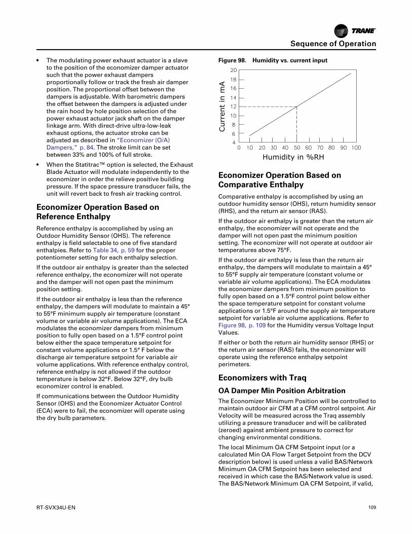
RT-SVX34U-EN 109
• The modulating power exhaust actuator is a slaveto the position of the economizer damper actuatorsuch that the power exhaust dampersproportionally follow or track the fresh air damperposition. The proportional offset between thedampers is adjustable. With barometric dampersthe offset between the dampers is adjusted underthe rain hood by hole position selection of thepower exhaust actuator jack shaft on the damperlinkage arm. With direct-drive ultra-low-leakexhaust options, the actuator stroke can beadjusted as described in “Economizer (O/A)Dampers,” p. 84. The stroke limit can be setbetween 33% and 100% of full stroke.
• When the Statitrac™ option is selected, the ExhaustBlade Actuator will modulate independently to theeconomizer in order the relieve positive buildingpressure. If the space pressure transducer fails, theunit will revert back to fresh air tracking control.
Economizer Operation Based onReference EnthalpyReference enthalpy is accomplished by using anOutdoor Humidity Sensor (OHS). The referenceenthalpy is field selectable to one of five standardenthalpies. Refer to Table 34, p. 59 for the properpotentiometer setting for each enthalpy selection.
If the outdoor air enthalpy is greater than the selectedreference enthalpy, the economizer will not operateand the damper will not open past the minimumposition setting.
If the outdoor air enthalpy is less than the referenceenthalpy, the dampers will modulate to maintain a 45°to 55°F minimum supply air temperature (constantvolume or variable air volume applications). The ECAmodulates the economizer dampers from minimumposition to fully open based on a 1.5°F control pointbelow either the space temperature setpoint forconstant volume applications or 1.5° F below thedischarge air temperature setpoint for variable airvolume applications. With reference enthalpy control,reference enthalpy is not allowed if the outdoortemperature is below 32°F. Below 32°F, dry bulbeconomizer control is enabled.
If communications between the Outdoor HumiditySensor (OHS) and the Economizer Actuator Control(ECA) were to fail, the economizer will operate usingthe dry bulb parameters.
Figure 98. Humidity vs. current input
Humidity in %RH
Curr
ent
in m
A
Economizer Operation Based onComparative EnthalpyComparative enthalpy is accomplished by using anoutdoor humidity sensor (OHS), return humidity sensor(RHS), and the return air sensor (RAS).
If the outdoor air enthalpy is greater than the return airenthalpy, the economizer will not operate and thedamper will not open past the minimum positionsetting. The economizer will not operate at outdoor airtemperatures above 75°F.
If the outdoor air enthalpy is less than the return airenthalpy, the dampers will modulate to maintain a 45°to 55°F supply air temperature (constant volume orvariable air volume applications). The ECA modulatesthe economizer dampers from minimum position tofully open based on a 1.5°F control point below eitherthe space temperature setpoint for constant volumeapplications or 1.5°F around the supply air temperaturesetpoint for variable air volume applications. Refer toFigure 98, p. 109 for the Humidity versus Voltage InputValues.
If either or both the return air humidity sensor (RHS) orthe return air sensor (RAS) fails, the economizer willoperate using the reference enthalpy setpointperimeters.
Economizers with Traq
OA Damper Min Position ArbitrationThe Economizer Minimum Position will be controlled tomaintain outdoor air CFM at a CFM control setpoint. AirVelocity will be measured across the Traq assemblyutilizing a pressure transducer and will be calibrated(zeroed) against ambient pressure to correct forchanging environmental conditions.
The local Minimum OA CFM Setpoint input (or acalculated Min OA Flow Target Setpoint from the DCVdescription below) is used unless a valid BAS/NetworkMinimum OA CFM Setpoint has been selected andreceived in which case the BAS/Network value is used.The BAS/Network Minimum OA CFM Setpoint, if valid,
SSeeqquueennccee ooff OOppeerraattiioonn

110 RT-SVX34U-EN
overrides the DCV CO2 reset calculation of Min OAFlow Target as well.
The measured OA CFM value from the local sensorinput will normally be used for this function. At thistime OA CFM value from other sources is notsupported.
The algorithm used for this function will be P+I, withintegration occurring only when outside the deadband.As long as the measured airflow is within thedeadband, the control will be satisfied. When the OACFM value is above the upper deadband limit thealgorithm will decrease the Traq OA Min DamperPosition Request allowing less fresh air into the space.When the OA CFM value is below the lower deadbandlimit the algorithm will increase the Traq OA DamperMin Position Request allowing more fresh air into thespace. The OA CFM Deadband will be hard coded to +/-250 CFM.
Traq with Demand Controlled Ventilation(DCV)If Demand Controlled Ventilation is enabled, theMinimum OA CFM control point will be modified byhigh CO2 concentrations resetting the setpointbetween Design and DCV Minimum OA CFM setpointlimits. The Traq airflow control functionality describedabove will then use the calculated Min OA Flow Targetfor determining the Traq OA Minimum PositionRequest.
Modulating Hot Gas ReheatSequence of OperationWhen the relative humidity in the controlled space (asmeasured by the sensor assigned to space humiditysensing) rises above the space humidity setpoint,compressors and the supply fan will energize to reducethe humidity in the space. All compressors on bothrefrigerant circuits will be staged up during active hotgas reheat.
A Voyager Commercial Rooftop unit can contain one ortwo refrigerant circuits. Units with hot gas reheat willhave one circuit with an outdoor condenser coil locatedin the outdoor section for normal head pressure controland a reheat coil located in the indoor air streamsection for supply air reheat; both coils are for thesame circuit. For 40-50 ton Voyager Commercial unitsthe reheat circuit is circuit# 2. For 27.5-35 ton VoyagerCommercial units there is only one circuit.
During hot gas reheat mode, the CLV and RHP willmodulate which will allow refrigerant to flow throughboth the condenser coil and the reheat coil. The RHPwill be de-energized when in hot gas reheat mode.
During hot gas reheat mode, the Supply AirTemperature is controlled to the Supply Air ReheatSetpoint by controlling the reheat and coolingmodulating valve position. The range for the Supply
Air Reheat Setpoint is 65°F to 80°F and the default is70°F. The Supply Air Reheat Setpoint is adjusted byusing a potentiometer on the RTOM.
During cooling operation, the cooling valve (CLV) willbe open 100% and the reheat valve (RHV) will be closedwhich will allow refrigerant to flow through thecondenser coil and not the reheat coil. During coolingmode the reheat pump-out solenoid (RHP) will also beenergized to allow refrigerant to be removed from thereheat coil.
During cooling or hot gas reheat mode, to ensureproper oil distribution throughout the reheat andcooling condenser circuits, a purge is initiated by ahard coded purge interval timer. After the purgeinterval timer reaches 60 minutes, the unit performs apurge for a fixed 3-minute time period. During thisstate the reheat and cooling valve will be driven 50%and the reheat pump-out solenoid is energized.
See Hot Gas Reheat Low Pressure Control section forthe reheat low pressure control (RLP) function duringactive dehumidification.
See Hot Gas Reheat Frost Protection section for thecontrol scheme during active dehumidification.
See the Condenser Fan / Compressor sequence sectionfor Condenser fan staging during activedehumidification.
Sensible Cooling or Heating ControlOverrides Hot Gas Reheat ControlFor both multi-circuit and single circuit units, anysensible heating request will terminate hot gas reheatcontrol. If heating is active at the time a call for hot gasreheat control is received the heating operation mustcomplete and an additional 5 minutes from the timeheat is terminated must elapse before hot gas reheatwill be allowed.
NNoottee:: Occupied VAV operation in cooling mode willconsider a critical zone temperature and whenthe sensible cooling requirements of this zoneare not being met, the unit will terminate hot gasreheat control.
NNoottee:: Occupied CV and all unoccupied operation willterminate hot gas reheat if the sensible zonecooling requirements exceeds one-half theavailable cooling capacity of the unit.
Gas Heat Sequence Of OperationWhen heating is required, the RTRM initiates theheating cycle through the ignition control module(IGN). The IGN normally open contacts close to startthe combustion blower motor (CBM) on high speed.Next, the IGN control energizes the hot surface igniter(IP) for 45 seconds. After a preheat period, the gasvalve (GV) is energized for approximately 7 seconds. Ifthe burner lights, the gas valve remains energized. Ifthe burner fails to ignite, the ignition module will
SSeeqquueennccee ooff OOppeerraattiioonn

RT-SVX34U-EN 111
attempt two retries and then lock out if flame is notproven. The unit will attempt to ignite at 60 minuteintervals until the heating call is removed.
An IGN lockout due to flame loss can be reset by:
• Open and close the main power disconnect switch.
• Switch the MODE switch on the zone sensor to“Off” and then to the desired position (VAV units –remove and reapply the mode input).
• Allow the IGN to reset automatically after one hour.
When ignition takes place, the hot surface igniter (IP) isde-energized and functions as the flame sensor.
Two Stage—If, after 60 seconds, the unit requires 1ststage heating only, the IGN will change the combustionblower from high speed to low speed. If additionalheating is required and first stage heat has beenoperating for a minimum of 10 seconds, the IGNinducer relay will change the combustion blower motor(CBM) to high speed, delivering second stage heatcapacity.
Modulating—Units with modulating heat will fire themodulating bank first at high fire for 60 seconds. Theunit will then modulate the heater to the necessaryrate. If the modulating heat bank cannot satisfy thezone needs alone, the second bank will come on andthe modulating will find the appropriate operatingpoint.
Constant Volume (CV) Unit FanOperationIf the fan selection switch is in the “AUTO” position forconstant volume units, the RTRM will delay starting thesupply fan for 60 seconds to allow the heat exchangerto warm up. When the zone temperature rises abovethe heating setpoint, the IGN control module willterminate the heat cycle. The supply fan remainsenergized for an additional 90 seconds.
Variable Air Volume (VAV) Unit FanOperation (2 Stage and Modulating GasHeat)During Unoccupied heating, Morning Warm up, andDaytime Warm up mode, the VFD must be at 100%.Therefore, before the unit can heat, the VHR relay musthave been energized for at least 6 minutes to ensurethat the VAV boxes have driven to maximum. Forexample, 6 minutes after a Daytime Warm up mode isinitiated, the VFD output will go to 100% and then theheat cycle will begin. The VHR relay is energized duringUnoccupied mode, Morning Warm up mode, andDaytime Warm up mode.
Variable Air Volume (VAV) Unit FanOperation (Modulating Gas Heat Only)During Changeover Heat (LTB5-1 shorted to LTB5-2),the unit will heat to the Supply Air Heating Setpoint +/-
7ºF. The VFD will modulate to maintain the StaticPressure Setpoint.
Ignition Control ModuleThere is a green LED located on the ignition module.Any time the Ignition module is powered, the LED willbe on to provide status of the ignition system.
• Steady OFF - no power/ internal failure
• Steady ON - no diagnostic, no call for heat
• Slow flash rate ¾ second on, ¼ second off - normalcall for heat
Error Code Flashes• One flash - Communication loss between RTRM
and IGN
• Two flashes - System lockout; failed to detect orsustain flame (3 tries, lockout after 3rd try)
• Three flashes - Not used
• Four flashes - High limit switch TCO1, TCO2, orTCO3 open (auto reset)
• Five flashes - Flame sensed and gas valve notenergized; or flame sensed and no call for heat(auto reset)
The pause between groups of flashes is approximatelytwo seconds.
High Temperature Limit Operation andLocationAll of the heater limit controls are automatic reset. Thehigh limit cutouts (TCO1) and/or (TCO3) protect againstabnormally high supply air temperature. The fan failurelimit (TCO2) protects against abnormally high heatbuild up due to excessive high limit (TCO1) (TCO3)cycling if the indoor fan motor (IDM) fails. If TCO1,TCO2, or TCO3 open during a heating call, the heat willshut down and the supply fan will be forced to run. Theheat will automatically restart should the TCO circuitre-close during an active heating call. While the TCOcircuit is open, a heat fail diagnostic will be sent fromthe IGN to the RTRM.
The TCO1 and TCO3 is located in the bottom rightcorner of the burner assemblies on both downflow andhorizontal units. TCO2 is located on the IDM partitionpanel; below and to the right of the blower housing ondownflow units. On horizontal units, TCO2 is locatedon the IDM partition panel above the blower housing.
Electric Heat Sequence OfOperationConstant Volume (CV)When heat is required and the Fan selection switch is inthe “AUTO” position for constant volume applications,the RTRM energizes the Supply Fan approximately one
SSeeqquueennccee ooff OOppeerraattiioonn

112 RT-SVX34U-EN
second before energizing the first stage electric heatcontactor (AH). A 10 seconds minimum “off” timedelay must elapse before the first stage heater isactivated. When the heating cycle is completed, theRTRM de-energizes the Fan and the heater contactor(AH) at the same time.
The RTRM cycles the first stage of heat as required tomaintain zone temperature. If the first stage cannotsatisfy the heating requirement, the RTRM energizesthe second stage electric heat contactors (BH) and (CH)providing first stage has been on for at least 10seconds or the second stage has been off for at least 10seconds. (CH contactor is used on 54KW and largerheaters.)
The RTRM cycles the second stage electric heat asrequired to maintain the zone temperature.
Variable Air Volume (VAV)During Unoccupied heating, Morning Warm up, orDaytime Warm up, the VHR relay will be energized forat least 6 minutes and the VFD output will go to 100%.The heaters will stage on and off to satisfy the zonetemperature setpoint.
Variable Air VolumeApplications (Single Zone VAV)Sequence of OperationOccupied Cooling OperationFor normal Cooling operation, available Coolingcapacity will be staged or modulated in order to meetthe calculated discharge air setpoint between the userselected upper and lower limits. If the current activecooling capacity is controlling the discharge air withinthe deadband no additional Cooling capacity changewill be requested. As the Discharge Air Temperaturerises above the deadband the control will requestadditional capacity as required (additional compressoroperation or economizer). As the Discharge AirTemperature falls below the deadband the algorithmwill request a reduction in active capacity.
Economizer CoolingDuring normal Economizer Cooling, the fan speed willoperate at its minimum. However, if the economizer isable to meet the demand alone, due to desirableambient conditions, the supply fan speed will beallowed to increase above the minimum prior toutilizing mechanical cooling. Note that EconomizerEnable/Disable decisions will be made based on theprevious sections, however, the economizer controlpoint will now be variable based on the zone coolingdemand.
Economizer Enabled at Cooling StartOnce the unit has a request for economizer cooling andthe unit has met all Cool mode transition requirements,the Economizer will open beyond minimum positionwith the Supply Fan Speed at 45% in order to meet thecalculated discharge air setpoint value. If theeconomizer at 100% alone cannot meet the activedischarge air setpoint, the Supply Fan Speed willincrease to 100% for 3 minutes. Once the 3 minutecompressor inhibit delay has expired, compressors willbe allowed to energize to meet the space demand. Thesupply fan speed output will continue to modulate inorder to meet the zone cooling requirements.
Once compressors are being utilized for additionalcooling capacity, the economizer will be forced to 100%if enabled. As the cooling capacity begins to stage back(less cooling load) the economizer will remain at 100%,if enabled, until all compressors have de-energized.
Economizer Enabled to DisabledIf the economizer is enabled and the unit is activelycooling with the economizer, if the economizerbecomes disabled the economizer will be closed to theactive minimum position and compressors will beallowed to stage without delay if the minimum offtimers have expired and there is a Cooling demandrequesting compressor operation. During thistransition, the fan will continue to modulate in order tomeet the space demand.
Economizer Disabled to EnabledIf compressors are energized for Cooling and theeconomizer was disabled, but becomes enabled due todesirable ambient conditions, the economizer will beforced to 100% as on traditional VAV units.
Compressor CoolingCompressor output control and protection schemeswill function much like on non-SZ VAV units. Normalcompressor HPC and LPC control will remain in effectas well as normal 3-minute minimum on, off, and inter-stage timers. Also, the condenser fans will becontrolled as on non-SZ VAV units and compressorstaging sequences will be as described in Table 23, p.46 and Table 24, p. 47 based on unit tonnageconfiguration and lead/lag status.
Cooling SequenceIf the control determines that there is a need forcompressor stages in order to meet the discharge airrequirements, once supply fan proving has been made,the unit will begin to stage compressors accordingly.Note that a 5 second delay will be enforced betweenthe command for supply fan output operation and thecommand for compressor output operation. This delayis enforced to ensure that the supply fan is energizedand ramping up to operating speed prior to energizingcompressors.
SSeeqquueennccee ooff OOppeerraattiioonn

RT-SVX34U-EN 113
As the zone cooling demand continues to increase, ifadditional capacity is required, the supply fan outputwill be modulated above minimum speed in order tomeet the zone requirements.
NNoottee:: The supply fan speed will remain at thecompressor stage's associated minimum valueuntil the control requires additional capacity tomeet the zone demand.
As the cooling load in the zone decreases the controlwill reduce the speed of the fan down to minimum percompressor stage and control the compressor outputsaccordingly. As the compressors begin to de-energize,the Supply Fan speed will fall back to the CoolingStage's associated minimum fan speed but not below.As the load in the zone continues to drop, coolingcapacity will be reduced in order to maintain thecalculated discharge air setpoint.
Cooling Stages Minimum Fan SpeedAs the unit begins to stage compressors to meet thecooling demand, the following minimum Supply FanSpeeds will be utilized for each corresponding CoolingStage. Note that the Supply Fan Speed will be allowedto ramp up beyond the minimum speed in order tomeet the zone cooling demand.
2-Stage Cooling Units (27.5-35T Units)The minimum fan speed for units with 2 stages of DXCooling will be 45% of the unit's full airflow capacity. AtStage 1 of DX Cooling the Fan Speed will be at aminimum of 45% and at Stage 2 of DX Cooling the FanSpeed will be at a minimum of 67%.
3-Stage Cooling Units (40-50T StandardEfficiency VAV Units)The minimum fan speed for units with 3 stages of DXCooling will be 45% of the unit's full airflow capacity. AtStage 1 of DX Cooling the Fan Speed will be at aminimum of 45% and at Stages 2 and 3 of DX Coolingthe Fan Speed will be at a minimum of 67%.
5-Stage High Efficiency Cooling Units and 40-50TStandard Efficiency CV UnitsThe minimum fan speed for units with 5 stages of DXCooling will be 33% of the unit's full airflow capacity. AtStage 1 of DX Cooling the Fan Speed will be at aminimum of 33%.
Add % for other stages 2-5.
Occupied Heating OperationOccupied Heating operation on units configured withSingle Zone VAV control will utilize two separatecontrol methodologies based on heatingconfigurations. For all “Staged” Heating types (Electricand Gas), the unit will utilize 100% full airflow during allactive heating periods like traditional Constant Volumeunits. For Modulating Gas heat units, the unit will havethe ability to control the discharge air temperature to
the calculated discharge air heating setpoint in order tomaintain the Zone Temperature to the Zone Heatingsetpoint.
Staged Heating OperationFor units configured with Staged Heat once the controldetermines that there is an active heating capacityrequest, the unit will energize the Supply Fan and rampup to full speed. The control methodology duringActive Heating on units configured with Staged Heattypes will be identical to traditional Constant Volumeunits; heating stages will be energized/de-energized tomeet the Zone Heating demand. Note that all Electricand Gas Heat staging sequences will be identical to ason Constant Volume units.
Modulating Heat Operation with SZVAVHeatingUnits configured with Modulating Gas Heat will utilizetrue Single Zone VAV control in the same manner asduring Active Cooling.
Heating SequenceOnce the unit has met all Auto-Changeoverrequirements and the control determines that there is aspace heating demand, the unit will transition into zoneheating. Once the Discharge Air Temperature fallsbelow the calculated discharge air temperaturesetpoint, the unit will initiate the Modulating Heatoutput request and control the supply fan at minimumspeed. At this point, the Modulating Heat output will becontrolled to maintain the discharge air temperaturerequirements and the supply fan speed will becontrolled between 58%-100% to meet the zone heatingrequirements.
As the heating load in the zone decreases the fan speedwill decrease down to minimum (58%) and control themodulating heat output as necessary to meet thedischarge air heating requirements. As the load in thezone continues to drop the fan speed will bemaintained at this minimum airflow and themodulating heat output will be controlled accordingly.
NNoottee:: The gas heat staging sequences will be the sameon SZ VAV units as on traditional CV units.
Unoccupied Cooling and HeatingOperationFor SZ VAV units, the unit will control Heating, Cool,and Hot Gas Reheat as during Occupied periods usingthe normal heating and cooling Single Zone VAValgorithms. In Unoccupied periods the unit will utilizesetback setpoints, a 0% Minimum OA Damper position,and Auto fan mode operation as on normal ConstantVolume units.
SSeeqquueennccee ooff OOppeerraattiioonn
114 RT-SVX34U-EN
Modulating Hot Gas Reheat OperationSinge Zone VAV units support modulating hot gasreheat operation. Most functions will be identical to hotgas reheat control on CV and Traditional VAV units.
Entering Hot Gas ReheatAt startup a zone heating or cooling demand willprevent hot gas reheat operation as on a non-SingleZone VAV unit. At this point the unit will performnormal sensible cooling or heating control until therespective setpoint is satisfied.
After startup, the unit will monitor the unit conditionsto determine when to enter and leave hot gas reheatmode. As long as the unit is not actively heating oractively cooling with more than half the unit designmechanical cooling capacity for Standard Efficientunits and have a call for stage 3 or below for HighEfficient units (5 stage units), hot gas reheat mode willbe allowed (also the unit has not been disabled due tothe override limits described below).
When hot gas reheat mode is entered the unit will:
• Energize the Supply Fan, if not already ON, andramp the Fan Speed output up to 80% airflow.
• Stage up all compressors with ~2 seconds betweenstages.
• Command the OA damper to minimum position.
• The Supply Air Reheat setpoint (R130 located onthe RTOM) will become the maximum discharge aircontrol setpoint.
• The reheat and cooling valves will be modulated tomeet the calculated discharge air setpoint.
Leaving Hot Gas ReheatOn a call to leave hot gas reheat mode the unit willperform the following:
• Mechanical cooling will stage back to 50% (Cool 1)of the available capacity then will be released tonormal Single Zone VAV control to meet the spacedemand.
• The economizer will be released to normal control.
• The Supply Fan output will be released to meet thespace load.
• The cooling valve will be driven to 100% and thereheat valve will be driven to 0%.
• The Reheat Pumpout relay will be energized if thereheat circuit is requested or de-energized if thereheat circuit de-energizes.
Typical causes to leave hot gas reheat are:
• Space humidity levels have fallen below the ActiveOcc/Unocc Dehumidification Setpoint -5%Dehumidification Hysteresis Offset,
• The zone temperature has dropped too close to theZone Heating Setpoint in any unit mode (ZoneTemp. ? ZHSP + 0.5°F).
• The zone temperature rises above the Zone CoolingSetpoint +2°F in any unit mode.
• Entering Evaporator Temperature falls too low orFroststat input becomes active.
• Dehumidification/Reheat becomes disabled.
Hot Gas Reheat OverridesSensible cooling or heating control overrides hot gasreheat control. Any heating request will terminate hotgas reheat control. If heating is active at the time a callfor hot gas reheat control is received the heatingoperation must complete and an additional 5 minutesfrom the time heat is terminated must elapse beforehot gas reheat will be allowed. Hot gas reheat will alsobe disabled if any of the functional disables that applyto CV or traditional VAV have gone active.
Purge Mode (Comfort and Dehumidification)Purge cycle operation will operate identically to Purgeon non-Single Zone VAV Hot Gas Reheat units; if theReheat Circuit operates in one mode (dehumidificationor cooling) for a cumulative 60 minutes the unit willinitiate a 3-minute Purge cycle with all compressorsenergized, the Cooling and Reheat Valves at 50%, andthe Reheat Pumpout relay de-energized.
During an active Purge Cycle the Supply Fan Speed willoperate at the appropriate speed based on the activecompressor step. If a dehumidification purge isinitiated, the unit will run at 80%, if performing acooling purge the supply fan will track based on theappropriate minimum speed for the associated numberof compressors energized. After the Purge Cycle iscomplete, the Supply Fan will be released to normalcontrol based on the Cooling/Dehumidificationdemand.
Hot Gas Reheat - Humidistat OperationA humidistat input located on the Options module willbe supported as on non-SZ VAV.
Other Hot Gas Reheat Related TopicsThe following aspects of Single Zone VAV unitsconfigured with Modulating hot gas reheat will operateidentically to non-Single Zone VAV units:
• Outdoor Fan Control.
• Low Pressure/High Pressure Cutout input handling.
• Function Enable/Disable Details.
Failure and Overriding ConditionsCertain failure and overriding conditions requirespecial handling of the Supply Fan Speed on unitsconfigured with Single Zone VAV. See below for a listof these conditions:
• Supply Fan Proving Failure - If a Supply Fan Provingfailure is detected the Supply Fan will be de-energized after 40s of run time and the Fan Speedoutput will go to 0 Vdc (0%).
SSeeqquueennccee ooff OOppeerraattiioonn

RT-SVX34U-EN 115
• Ventilation Override Mode - If a VOM goes active inwhich the Supply Fan is commanded ON (Purge,Pressurize, etc.) the Supply Fan will be energizedand the Fan Speed output will ramp to 100%.
• Zone Temperature Sensor Failure - If the ActiveZone Temperature input goes out of range, the unitwill discontinue all Heating, Cooling, and Hot GasReheat operation.
• Supply Air Temperature Sensor Failure - If theSupply Air Temperature input goes out of range,the unit will revert back to Full Airflow, TraditionalCV control. The unit will call out a Supply AirTemperature Sensor Failure Alarm, the RTRMSystem LED will flash the 2-blink error code, andthe Zone Sensor Heat (Modulating Heat Only) andCool LEDs will flash.
• Frostat Failure - If the unit has a Froststat Failureoccur, all active Heating, Cooling, and Hot GasReheat will be de-energized immediately and theSupply Fan will ramp up to 100%.
• Heat Failure (High Temp. Limit Trip) - If a unitconfigured with Gas Heat has a High Temp. Limittrip the Supply Fan will be requested to remain ONand the Fan Speed output will ramp to full speed.
Low Pressure Control (LPC)Sequence of Operation (ReliaTelControl)When the LPC is opened for one (1) continuous second,the compressor for that circuit is turned offimmediately. The compressor will not be allowed torestart for a minimum of three (3) minutes.
If four consecutive open conditions occur during thefirst three minutes of operation, the compressor will belocked out, a diagnostic communicated to ICSTM ifapplicable, and a manual reset will be required torestart the compressor.
High Pressure Control andTemperature Discharge Limit(ReliaTel Control)The Temperature Discharge Limit (TDL) is located inthe Compressor Output circuit and is connected inseries with the High Pressure Control (HPC). The RTRMwill register an auto reset lockout if either the highpressure control switch or the temperature dischargelimit opens during compressor operation. If thecompressor output circuit is opened four consecutivetimes during compressor operation, the RTRM willgenerate a manual reset lockout.
SSeeqquueennccee ooff OOppeerraattiioonn

116 RT-SVX34U-EN
MaintenanceFan Belt AdjustmentThe supply fan belts must be inspected periodically toassure proper unit operation.
Replacement is necessary if the belts appear frayed orworn. Units with dual belts require a matched set ofbelts to ensure equal belt length. When installing newbelts, do not stretch them over the sheaves; instead,loosen the adjustable motor-mounting base.
Once the new belts are installed, adjust the belt tensionusing a Browning or Gates tension gauge (orequivalent) illustrated in Figure 99, p. 116.
Figure 99. Typical belt tension gauge
Deflection = Belt Span (in.)64
Deflection = Belt Span (mm)152
Force Scale
Span ScaleLargeO-Ring
SmallO-RingBelt Span
WWAARRNNIINNGGHHaazzaarrddoouuss VVoollttaaggee ww//CCaappaacciittoorrss!!FFaaiilluurree ttoo ddiissccoonnnneecctt ppoowweerr aanndd ddiisscchhaarrggeeccaappaacciittoorrss bbeeffoorree sseerrvviicciinngg ccoouulldd rreessuulltt iinn ddeeaatthh oorrsseerriioouuss iinnjjuurryy..DDiissccoonnnneecctt aallll eelleeccttrriicc ppoowweerr,, iinncclluuddiinngg rreemmootteeddiissccoonnnneeccttss aanndd ddiisscchhaarrggee aallll mmoottoorr ssttaarrtt//rruunnccaappaacciittoorrss bbeeffoorree sseerrvviicciinngg.. FFoollllooww pprrooppeerrlloocckkoouutt//ttaaggoouutt pprroocceedduurreess ttoo eennssuurree tthhee ppoowweerrccaannnnoott bbee iinnaaddvveerrtteennttllyy eenneerrggiizzeedd.. FFoorr vvaarriiaabblleeffrreeqquueennccyy ddrriivveess oorr ootthheerr eenneerrggyy ssttoorriinnggccoommppoonneennttss pprroovviiddeedd bbyy TTrraannee oorr ootthheerrss,, rreeffeerr ttootthhee aapppprroopprriiaattee mmaannuuffaaccttuurreerr’’ss lliitteerraattuurree ffoorraalllloowwaabbllee wwaaiittiinngg ppeerriiooddss ffoorr ddiisscchhaarrggee ooffccaappaacciittoorrss.. VVeerriiffyy wwiitthh aa CCAATT IIIIII oorr IIVV vvoollttmmeetteerrrraatteedd ppeerr NNFFPPAA 7700EE tthhaatt aallll ccaappaacciittoorrss hhaavveeddiisscchhaarrggeedd..
1. To determine the appropriate belt deflection:
a. Measure the center-to-center distance, ininches, between the fan sheave and the motorsheave.
b. Divide the distance measured in Step 1a by 64;the resulting value represents the amount ofbelt deflection for the proper belt tension.
2. Set the large O-ring on the belt tension gauge at thedeflection value determined in Step 1b.
3. Set the small O-ring at zero on the force scale of thegauge.
4. Place the large end of the gauge on the belt at thecenter of the belt span. Depress the gauge plungeruntil the large O-ring is even with the of the secondbelt or even with a straightedge placed across thesheaves.
5. Remove the tension gauge from the belt. Noticethat the small O-ring now indicates a value otherthan zero on the force scale. This value representsthe force (in pounds) required to deflect the belt(s)the proper distance when properly adjusted.
6. Compare the force scale reading in step 5 with theappropriate “force” value in Table 66, p. 117. If theforce reading is outside of the listed range for thetype of belts used, either readjust the belt tension orcontact a qualified service representative.
NNoottee:: The actual belt deflection force must notexceed the maximum value shown in Table66, p. 117 .
7. Recheck the new belt's tension at least twice duringthe first 2 to 3 days of operation. Readjust the belttension as necessary to correct for any stretchingthat may have occurred. Until the new belts are“run in”, the belt tension will decrease rapidly asthey stretch.
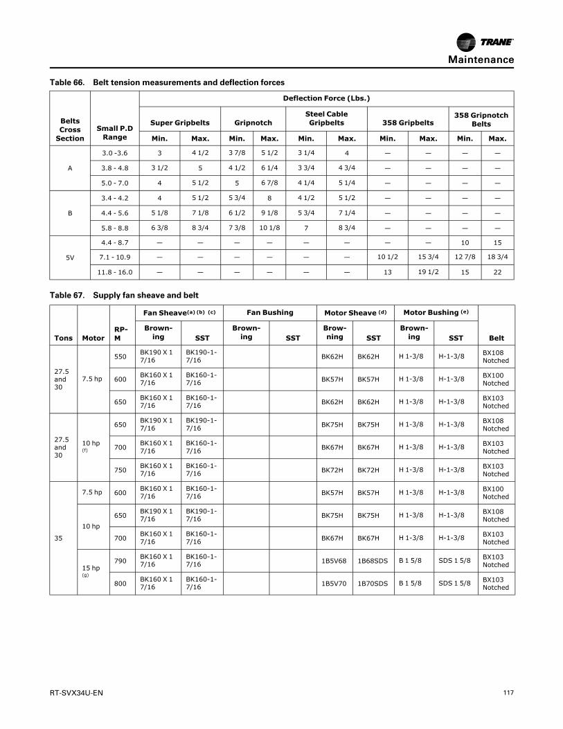
RT-SVX34U-EN 117
Table 66. Belt tension measurements and deflection forces
BeltsCrossSection
Small P.DRange
Deflection Force (Lbs.)
Super Gripbelts GripnotchSteel CableGripbelts 358 Gripbelts
358 GripnotchBelts
Min. Max. Min. Max. Min. Max. Min. Max. Min. Max.
A
3.0 -3.6 3 4 1/2 3 7/8 5 1/2 3 1/4 4 — — — —
3.8 - 4.8 3 1/2 5 4 1/2 6 1/4 3 3/4 4 3/4 — — — —
5.0 - 7.0 4 5 1/2 5 6 7/8 4 1/4 5 1/4 — — — —
B
3.4 - 4.2 4 5 1/2 5 3/4 8 4 1/2 5 1/2 — — — —
4.4 - 5.6 5 1/8 7 1/8 6 1/2 9 1/8 5 3/4 7 1/4 — — — —
5.8 - 8.8 6 3/8 8 3/4 7 3/8 10 1/8 7 8 3/4 — — — —
5V
4.4 - 8.7 — — — — — — — — 10 15
7.1 - 10.9 — — — — — — 10 1/2 15 3/4 12 7/8 18 3/4
11.8 - 16.0 — — — — — — 13 19 1/2 15 22
Table 67. Supply fan sheave and belt
Tons MotorRP-M
Fan Sheave(a) (b) (c) Fan Bushing Motor Sheave (d) Motor Bushing (e)
BeltBrown-ing SST
Brown-ing SST
Brow-ning SST
Brown-ing SST
27.5and30
7.5 hp
550 BK190 X 17/16
BK190-1-7/16 BK62H BK62H H 1-3/8 H-1-3/8 BX108
Notched
600 BK160 X 17/16
BK160-1-7/16 BK57H BK57H H 1-3/8 H-1-3/8 BX100
Notched
650 BK160 X 17/16
BK160-1-7/16 BK62H BK62H H 1-3/8 H-1-3/8 BX103
Notched
27.5and30
10 hp(f)
650 BK190 X 17/16
BK190-1-7/16 BK75H BK75H H 1-3/8 H-1-3/8 BX108
Notched
700 BK160 X 17/16
BK160-1-7/16 BK67H BK67H H 1-3/8 H-1-3/8 BX103
Notched
750 BK160 X 17/16
BK160-1-7/16 BK72H BK72H H 1-3/8 H-1-3/8 BX103
Notched
35
7.5 hp 600 BK160 X 17/16
BK160-1-7/16 BK57H BK57H H 1-3/8 H-1-3/8 BX100
Notched
10 hp650 BK190 X 1
7/16BK190-1-7/16 BK75H BK75H H 1-3/8 H-1-3/8 BX108
Notched
700 BK160 X 17/16
BK160-1-7/16 BK67H BK67H H 1-3/8 H-1-3/8 BX103
Notched
15 hp(g)
790 BK160 X 17/16
BK160-1-7/16 1B5V68 1B68SDS B 1 5/8 SDS 1 5/8 BX103
Notched
800 BK160 X 17/16
BK160-1-7/16 1B5V70 1B70SDS B 1 5/8 SDS 1 5/8 BX103
Notched
MMaaiinntteennaannccee
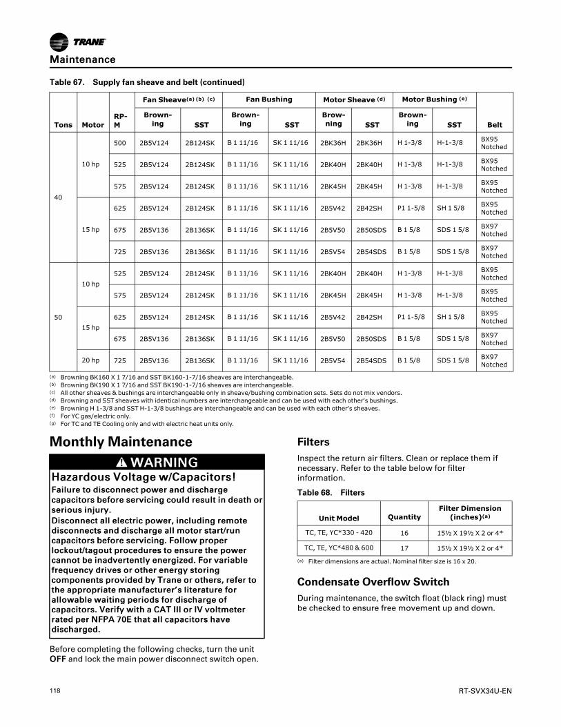
118 RT-SVX34U-EN
Table 67. Supply fan sheave and belt (continued)
Tons MotorRP-M
Fan Sheave(a) (b) (c) Fan Bushing Motor Sheave (d) Motor Bushing (e)
BeltBrown-ing SST
Brown-ing SST
Brow-ning SST
Brown-ing SST
40
10 hp
500 2B5V124 2B124SK B 1 11/16 SK 1 11/16 2BK36H 2BK36H H 1-3/8 H-1-3/8 BX95Notched
525 2B5V124 2B124SK B 1 11/16 SK 1 11/16 2BK40H 2BK40H H 1-3/8 H-1-3/8 BX95Notched
575 2B5V124 2B124SK B 1 11/16 SK 1 11/16 2BK45H 2BK45H H 1-3/8 H-1-3/8 BX95Notched
15 hp
625 2B5V124 2B124SK B 1 11/16 SK 1 11/16 2B5V42 2B42SH P1 1-5/8 SH 1 5/8 BX95Notched
675 2B5V136 2B136SK B 1 11/16 SK 1 11/16 2B5V50 2B50SDS B 1 5/8 SDS 1 5/8 BX97Notched
725 2B5V136 2B136SK B 1 11/16 SK 1 11/16 2B5V54 2B54SDS B 1 5/8 SDS 1 5/8 BX97Notched
50
10 hp525 2B5V124 2B124SK B 1 11/16 SK 1 11/16 2BK40H 2BK40H H 1-3/8 H-1-3/8 BX95
Notched
575 2B5V124 2B124SK B 1 11/16 SK 1 11/16 2BK45H 2BK45H H 1-3/8 H-1-3/8 BX95Notched
15 hp625 2B5V124 2B124SK B 1 11/16 SK 1 11/16 2B5V42 2B42SH P1 1-5/8 SH 1 5/8 BX95
Notched
675 2B5V136 2B136SK B 1 11/16 SK 1 11/16 2B5V50 2B50SDS B 1 5/8 SDS 1 5/8 BX97Notched
20 hp 725 2B5V136 2B136SK B 1 11/16 SK 1 11/16 2B5V54 2B54SDS B 1 5/8 SDS 1 5/8 BX97Notched
(a) Browning BK160 X 1 7/16 and SST BK160-1-7/16 sheaves are interchangeable.(b) Browning BK190 X 1 7/16 and SST BK190-1-7/16 sheaves are interchangeable.(c) All other sheaves & bushings are interchangeable only in sheave/bushing combination sets. Sets do not mix vendors.(d) Browning and SSTsheaves with identical numbers are interchangeable and can be used with each other's bushings.(e) Browning H 1-3/8 and SST H-1-3/8 bushings are interchangeable and can be used with each other's sheaves.(f) For YC gas/electric only.(g) For TC and TE Cooling only and with electric heat units only.
Monthly Maintenance
WWAARRNNIINNGGHHaazzaarrddoouuss VVoollttaaggee ww//CCaappaacciittoorrss!!FFaaiilluurree ttoo ddiissccoonnnneecctt ppoowweerr aanndd ddiisscchhaarrggeeccaappaacciittoorrss bbeeffoorree sseerrvviicciinngg ccoouulldd rreessuulltt iinn ddeeaatthh oorrsseerriioouuss iinnjjuurryy..DDiissccoonnnneecctt aallll eelleeccttrriicc ppoowweerr,, iinncclluuddiinngg rreemmootteeddiissccoonnnneeccttss aanndd ddiisscchhaarrggee aallll mmoottoorr ssttaarrtt//rruunnccaappaacciittoorrss bbeeffoorree sseerrvviicciinngg.. FFoollllooww pprrooppeerrlloocckkoouutt//ttaaggoouutt pprroocceedduurreess ttoo eennssuurree tthhee ppoowweerrccaannnnoott bbee iinnaaddvveerrtteennttllyy eenneerrggiizzeedd.. FFoorr vvaarriiaabblleeffrreeqquueennccyy ddrriivveess oorr ootthheerr eenneerrggyy ssttoorriinnggccoommppoonneennttss pprroovviiddeedd bbyy TTrraannee oorr ootthheerrss,, rreeffeerr ttootthhee aapppprroopprriiaattee mmaannuuffaaccttuurreerr’’ss lliitteerraattuurree ffoorraalllloowwaabbllee wwaaiittiinngg ppeerriiooddss ffoorr ddiisscchhaarrggee ooffccaappaacciittoorrss.. VVeerriiffyy wwiitthh aa CCAATT IIIIII oorr IIVV vvoollttmmeetteerrrraatteedd ppeerr NNFFPPAA 7700EE tthhaatt aallll ccaappaacciittoorrss hhaavveeddiisscchhaarrggeedd..
Before completing the following checks, turn the unitOOFFFF and lock the main power disconnect switch open.
FiltersInspect the return air filters. Clean or replace them ifnecessary. Refer to the table below for filterinformation.
Table 68. Filters
Unit Model QuantityFilter Dimension(inches)(a)
TC, TE, YC*330 - 420 16 15½ X 19½ X 2 or 4*
TC, TE, YC*480 & 600 17 15½ X 19½ X 2 or 4*
(a) Filter dimensions are actual. Nominal filter size is 16 x 20.
Condensate Overflow SwitchDuring maintenance, the switch float (black ring) mustbe checked to ensure free movement up and down.
MMaaiinntteennaannccee

RT-SVX34U-EN 119
Cooling Season
WWAARRNNIINNGGHHaazzaarrddoouuss VVoollttaaggee!!FFaaiilluurree ttoo ddiissccoonnnneecctt ppoowweerr bbeeffoorree sseerrvviicciinngg ccoouullddrreessuulltt iinn ddeeaatthh oorr sseerriioouuss iinnjjuurryy..DDiissccoonnnneecctt aallll eelleeccttrriicc ppoowweerr,, iinncclluuddiinngg rreemmootteeddiissccoonnnneeccttss bbeeffoorree sseerrvviicciinngg.. FFoollllooww pprrooppeerrlloocckkoouutt//ttaaggoouutt pprroocceedduurreess ttoo eennssuurree tthhee ppoowweerrccaann nnoott bbee iinnaaddvveerrtteennttllyy eenneerrggiizzeedd.. VVeerriiffyy tthhaatt nnooppoowweerr iiss pprreesseenntt wwiitthh aa vvoollttmmeetteerr..
☐ Check the unit’s drain pans and condensate pipingto ensure that there are no blockages.
☐ Inspect the evaporator and condenser coils for dirt,bent fins, etc. If the coils appear dirty, clean themaccording to the instructions described in “CoilCleaning” later in this section.
☐ Inspect the F/A-R/A damper hinges and pins toensure that all moving parts are securely mounted.Keep the blades clean as necessary.
WWAARRNNIINNGGRRoottaattiinngg CCoommppoonneennttss!!FFaaiilluurree ttoo ddiissccoonnnneecctt ppoowweerr bbeeffoorree sseerrvviicciinnggccoouulldd rreessuulltt iinn rroottaattiinngg ccoommppoonneennttss ccuuttttiinnggaanndd ssllaasshhiinngg tteecchhnniicciiaann wwhhiicchh ccoouulldd rreessuulltt iinnddeeaatthh oorr sseerriioouuss iinnjjuurryy..DDuurriinngg iinnssttaallllaattiioonn,, tteessttiinngg,, sseerrvviicciinngg aannddttrroouubblleesshhoooottiinngg ooff tthhiiss pprroodduucctt iitt mmaayy bbeenneecceessssaarryy ttoo wwoorrkk wwiitthh lliivvee aanndd eexxppoosseeddrroottaattiinngg ccoommppoonneennttss.. HHaavvee aa qquuaalliiffiieedd oorrlliicceennsseedd sseerrvviiccee iinnddiivviidduuaall wwhhoo hhaass bbeeeennpprrooppeerrllyy ttrraaiinneedd iinn hhaannddlliinngg eexxppoosseedd rroottaattiinnggccoommppoonneennttss,, ppeerrffoorrmm tthheessee ttaasskkss..
☐ Manually rotate the condenser fans to ensure freemovement and check motor bearings for wear.Verify that all of the fan mounting hardware is tight.
☐ Verify that all damper linkages move freely;lubricate with white grease, if necessary.
☐ Check supply fan motor bearings; repair or replacethe motor as necessary.
☐ Check the fan shaft bearings for wear. Replace thebearings as necessary.
NNoottee:: These bearings are considered permanentlylubricated for normal operation. For severedirty applications, if relubrication becomesnecessary, use a lithium based grease. SeeTable 69, p. 120 for recommended greases.
IImmppoorrttaanntt:: The bearings are manufactured using aspecial synthetic lithium-based greasedesigned for long life and minimumrelube intervals. Over lubrication can bejust as harmful as not enough.
☐ Use a hand grease gun to lubricate these bearings;add grease until a light bead appears all around theseal. Do not over lubricate! After greasing thebearings, check the setscrews to ensure that theshaft is held securely. Make sure that all bearingbraces are tight.
☐ Check the supply fan belt(s). If the belts are frayedor worn, replace them. Refer to the “Fan BeltAdjustment,” p. 116 for belt replacement andadjustments.
☐ Check the condition of the gasket around thecontrol panel doors. These gaskets must fitcorrectly and be in good condition to prevent waterleakage.
☐ Verify that all wire terminal connections are tight.
☐ Remove any corrosion present on the exteriorsurfaces of the unit and repaint these areas.
☐ Generally inspect the unit for unusual conditions (e.g., loose access panels, leaking piping connections,etc.)
☐ Make sure that all retaining screws are reinstalled inthe unit access panels once these checks arecomplete.
☐ With the unit running, check and record thefollowing:
– ambient temperature
– compressor oil level (each circuit)
– compressor suction and discharge pressures(each circuit)
– superheat and subcooling (each circuit)
Record this data on an “operator’s maintenance log”like the one shown in Table 70, p. 122. If the operatingpressures indicate a refrigerant shortage, measure thesystem superheat and system subcooling. Forguidelines, refer to “Charging by Subcooling,” p. 105.
IImmppoorrttaanntt:: Do not release refrigerant to theatmosphere! If adding or removingrefrigerant is required, the servicetechnician must comply with all federal,state and local laws. Refer to generalservice bulletin MSCU-SB-1 (latest edition).
Heating Season
WWAARRNNIINNGGHHaazzaarrddoouuss VVoollttaaggee!!FFaaiilluurree ttoo ddiissccoonnnneecctt ppoowweerr bbeeffoorree sseerrvviicciinngg ccoouullddrreessuulltt iinn ddeeaatthh oorr sseerriioouuss iinnjjuurryy..DDiissccoonnnneecctt aallll eelleeccttrriicc ppoowweerr,, iinncclluuddiinngg rreemmootteeddiissccoonnnneeccttss bbeeffoorree sseerrvviicciinngg.. FFoollllooww pprrooppeerrlloocckkoouutt//ttaaggoouutt pprroocceedduurreess ttoo eennssuurree tthhee ppoowweerrccaann nnoott bbee iinnaaddvveerrtteennttllyy eenneerrggiizzeedd.. VVeerriiffyy tthhaatt nnooppoowweerr iiss pprreesseenntt wwiitthh aa vvoollttmmeetteerr..
MMaaiinntteennaannccee

120 RT-SVX34U-EN
Before completing the following checks, turn the unitOOFFFF and lock the main power disconnect switch open.
☐ Inspect the unit air filters. If necessary, clean orreplace them.
☐ Check supply fan motor bearings; repair or replacethe motor as necessary.
☐ Check the fan shaft bearings for wear. Replace thebearings as necessary.
NNoottee:: These bearing are considered permanentlylubricated for normal operation. For severedirty applications, if relubrication becomesnecessary, use a lithium based grease. SeeTable 69, p. 120 for recommended greases.
IImmppoorrttaanntt:: The bearings are manufactured using aspecial synthetic lithium-based greasedesigned for long life and minimumrelube intervals. Over lubrication can bejust as harmful as not enough.
☐ Use a hand grease gun to lubricate these bearings;add grease until a light bead appears all around theseal. Do not over lubricate!
☐ After greasing the bearings, check the setscrews toensure that the shaft is held securely. Make surethat all bearing braces are tight.
☐ Inspect both the main unit control panel and heatsection control box for loose electrical componentsand terminal connections, as well as damaged wireinsulation. Make any necessary repairs.
☐ Gas units only - Check the heat exchanger(s) for anycorrosion, cracks, or holes.
☐ Check the combustion air blower for dirt orblockage from animals or insects. Clean asnecessary.
NNoottee:: Typically, it is not necessary to clean the gasfurnace. However, if cleaning does becomenecessary, remove the burner plate from thefront of the heat exchanger to access thedrum. Be sure to replace the existing gasketswith new ones before reinstalling the burner.
☐ Open the main gas valve and apply power to theunit heating section; then initiate a “Heat” testusing the startup procedure described in “Gas HeatUnits,” p. 105.
WWAARRNNIINNGGHHaazzaarrddoouuss GGaasseess aanndd FFllaammmmaabblleeVVaappoorrss!!FFaaiilluurree ttoo oobbsseerrvvee tthhee ffoolllloowwiinngg iinnssttrruuccttiioonnssccoouulldd rreessuulltt iinn eexxppoossuurree ttoo hhaazzaarrddoouuss ggaasseess,,ffuueell ssuubbssttaanncceess,, oorr ssuubbssttaanncceess ffrroommiinnccoommpplleettee ccoommbbuussttiioonn,, wwhhiicchh ccoouulldd rreessuulltt iinnddeeaatthh oorr sseerriioouuss iinnjjuurryy.. TThhee ssttaattee ooff CCaalliiffoorrnniiaahhaass ddeetteerrmmiinneedd tthhaatt tthheessee ssuubbssttaanncceess mmaayyccaauussee ccaanncceerr,, bbiirrtthh ddeeffeeccttss,, oorr ootthheerrrreepprroodduuccttiivvee hhaarrmm..IImmpprrooppeerr iinnssttaallllaattiioonn,, aaddjjuussttmmeenntt,, aalltteerraattiioonn,,sseerrvviiccee oorr uussee ooff tthhiiss pprroodduucctt ccoouulldd ccaauusseeffllaammmmaabbllee mmiixxttuurreess oorr lleeaadd ttoo eexxcceessssiivveeccaarrbboonn mmoonnooxxiiddee.. TToo aavvooiidd hhaazzaarrddoouuss ggaasseessaanndd ffllaammmmaabbllee vvaappoorrss ffoollllooww pprrooppeerriinnssttaallllaattiioonn aanndd sseettuupp ooff tthhiiss pprroodduucctt aanndd aallllwwaarrnniinnggss aass pprroovviiddeedd iinn tthhiiss mmaannuuaall..
☐ Verify that the ignition system operates properly.
Table 69. Grease recommendations
Recommended GreaseRecommended Operating
Range
Exxon Unirex #2
Mobil 532 -20 F to 250 F
Mobil SHC #220
Texaco Premium RB
Coil CleaningRegular coil maintenance, including annual cleaningenhances the unit’s operating efficiency by minimizingthe following:
• Compressor head pressure and amperage draw
• Water carryover
• Fan brake horsepower
• Static pressure losses
At least once each year—or more often if the unit islocated in a “dirty” environment—clean theevaporator, microchannel condenser, and reheat coilsusing the instructions outlined below. Be sure to followthese instructions as closely as possible to avoiddamaging the coils.
MMaaiinntteennaannccee

RT-SVX34U-EN 121
WWAARRNNIINNGGHHaazzaarrddoouuss CChheemmiiccaallss!!FFaaiilluurree ttoo ffoollllooww tthhiiss ssaaffeettyy pprreeccaauuttiioonn ccoouullddrreessuulltt iinn ddeeaatthh oorr sseerriioouuss iinnjjuurryy.. CCooiill cclleeaanniinnggaaggeennttss ccaann bbee eeiitthheerr aacciiddiicc oorr hhiigghhllyy aallkkaalliinnee aannddccaann bbuurrnn sseevveerreellyy iiff ccoonnttaacctt wwiitthh sskkiinn oorr eeyyeessooccccuurrss..HHaannddllee cchheemmiiccaall ccaarreeffuullllyy aanndd aavvooiidd ccoonnttaacctt wwiitthhsskkiinn.. AALLWWAAYYSS wweeaarr PPeerrssoonnaall PPrrootteeccttiivveeEEqquuiippmmeenntt ((PPPPEE)) iinncclluuddiinngg ggoogggglleess oorr ffaaccee sshhiieelldd,,cchheemmiiccaall rreessiissttaanntt gglloovveess,, bboooottss,, aapprroonn oorr ssuuiitt aassrreeqquuiirreedd.. FFoorr ppeerrssoonnaall ssaaffeettyy rreeffeerr ttoo tthhee cclleeaanniinnggaaggeenntt mmaannuuffaaccttuurreerr’’ss MMaatteerriiaallss SSaaffeettyy DDaattaa SShheeeettaanndd ffoollllooww aallll rreeccoommmmeennddeedd ssaaffee hhaannddlliinnggpprraaccttiicceess..
Refrigerant CoilsTo clean refrigerant coils, use a soft brush and asprayer.
IImmppoorrttaanntt:: DO NOT use any detergents withmicrochannel condenser coils. Pressurizedwater or air ONLY.
For evaporator and reheat coil cleaners, contact thelocal Trane Parts Center for appropriate detergents.
1. Remove enough panels from the unit to gain safeaccess to coils.
a. For the 50 ton unit with the 3rd coil closest tothe bulk-head, safe access can be gained byremoval of the unit side panels.
b. For the 40 ton and 50 ton units, access to the 2-row microchannel condenser coils removal ofthe corner posts will be necessary.
WWAARRNNIINNGGNNoo SStteepp SSuurrffaaccee!!FFaaiilluurree ttoo ffoollllooww iinnssttrruuccttiioonn bbeellooww ccoouulldd rreessuullttiinn ddeeaatthh oorr sseerriioouuss iinnjjuurryy..DDoo nnoott wwaallkk oonn tthhee sshheeeett mmeettaall ddrraaiinn ppaann..WWaallkkiinngg oonn tthhee ddrraaiinn ppaann ccoouulldd ccaauussee tthheessuuppppoorrttiinngg mmeettaall ttoo ccoollllaappssee aanndd rreessuulltt iinn tthheeooppeerraattoorr//tteecchhnniicciiaann ffaalllliinngg..
NNoottee:: Before attempting to enter the unit,bridge between the main supports.Bridging may consist of multiple 2 by 12boards or sheet metal grating.
2. Straighten any bent coil fins with a fin comb.
3. For accessible areas, remove loose dirt and debrisfrom both sides of the coil. For dual rowmicrochannel condenser coil applications, seekpressure coil wand extension through the localTrane Parts Center.
4. When cleaning evaporator and reheat coils, mix thedetergent with water according to themanufacturer’s instructions. If desired, heat thesolution to 150° F maximum to improve itscleansing capability.
IImmppoorrttaanntt:: DO NOT use any detergents withmicrochannel coils. Pressurized wateror air ONLY.
5. Pour the cleaning solution into the sprayer. If ahigh-pressure sprayer is used:
a. The minimum nozzle spray angle is 15 degrees.
b. Do not allow sprayer pressure to exceed 600 psi.
c. Spray the solution perpendicular (at 90 degrees)to the coil face.
d. For evaporator and reheat coils, maintain aminimum clearance of 6" between the sprayernozzle and the coil. For microchannel condensercoils, optimum clearance between the sprayernozzle and the microchannel coil is 1"-3”.
6. Spray the leaving-airflow side of the coil first; thenspray the opposite side of the coil. For evaporatorand reheat coils, allow the cleaning solution tostand on the coil for five minutes.
7. Rinse both sides of the coil with cool, clean water.
8. Inspect both sides of the coil; if it still appears to bedirty, repeat Steps 6 and 7.
9. Reinstall all of the components and panels removedin Step 1; then restore power to the unit.
10. For evaporator and reheat coils, use a fin comb tostraighten any coil fins which were inadvertentlybent during the cleaning process.
Microchannel Condenser Coil Repair andReplacementIf microchannel condenser coil repair or replacement isrequired, refer to General Service Bulletin RT-SVB83*-EN for further details.
Final ProcessRecord the unit data in the blanks provided.
MMaaiinntteennaannccee

122 RT-SVX34U-EN
Table70.
Sam
plemaintenance
log
Date
Current
Ambient
TempF/
C
RefrigerantCircuit#1
RefrigerantCircuit#2
Com
pr.
OilLevel
Suct.
Press.
Psig/
kPa
Disch.
Press
Psig/
kPa
Liquid
Press
Psig/
kPa
Super-
heatF/C
Sub-
coolF/C
Com
pr.
OilLevel
Suct.
Press.
Psig/
kPa
Disch.
Press
Psig/
kPa
Liquid
Press
Psig/
kPa
Super-
heatF/C
Sub-
coolF/C
-ok-low
-ok-low
-ok-low
-ok-low
-ok-low
-ok-low
-ok-low
-ok-low
-ok-low
-ok-low
-ok-low
-ok-low
-ok-low
-ok-low
-ok-low
-ok-low
-ok-low
-ok-low
-ok-low
-ok-low
-ok-low
-ok-low
-ok-low
-ok-low
-ok-low
-ok-low
-ok-low
-ok-low
MMaaiinntteennaannccee

RT-SVX34U-EN 123
Fall RestraintWWAARRNNIINNGG
FFaalllliinngg OOffff EEqquuiippmmeenntt!!FFaaiilluurree ttoo ffoollllooww iinnssttrruuccttiioonnss bbeellooww ccoouulldd rreessuulltt iinnddeeaatthh oorr sseerriioouuss iinnjjuurryy..TThhiiss uunniitt iiss bbuuiilltt wwiitthh ffaallll rreessttrraaiinntt sslloottss llooccaatteedd oonnuunniitt ttoopp tthhaatt MMUUSSTT bbee uusseedd dduurriinngg sseerrvviicciinngg..TThheessee sslloottss aarree ttoo bbee uusseedd wwiitthh ffaallll rreessttrraaiinntteeqquuiippmmeenntt tthhaatt wwiillll nnoott aallllooww aann iinnddiivviidduuaall ttoorreeaacchh tthhee uunniitt eeddggee.. HHoowweevveerr ssuucchh eeqquuiippmmeenntt wwiillllNNOOTT pprreevveenntt ffaalllliinngg ttoo tthhee ggrroouunndd,, aass tthheeyy aarree NNOOTTddeessiiggnneedd ttoo wwiitthhssttaanndd tthhee ffoorrccee ooff aa ffaalllliinnggiinnddiivviidduuaall..
The fall restraint is located approximately 3 feet fromthe unit edge.
Figure 100. Fall restraint
Fall Restraint
Refrigeration System
WWAARRNNIINNGGRR--441100AA RReeffrriiggeerraanntt uunnddeerr HHiigghheerrPPrreessssuurree tthhaann RR--2222!!FFaaiilluurree ttoo uussee pprrooppeerr eeqquuiippmmeenntt oorr ccoommppoonneennttss aassddeessccrriibbeedd bbeellooww,, ccoouulldd rreessuulltt iinn eeqquuiippmmeenntt ffaaiilliinnggaanndd ppoossssiibbllyy eexxppllooddiinngg,, wwhhiicchh ccoouulldd rreessuulltt iinnddeeaatthh,, sseerriioouuss iinnjjuurryy,, oorr eeqquuiippmmeenntt ddaammaaggee..TThhee uunniittss ddeessccrriibbeedd iinn tthhiiss mmaannuuaall uussee RR--441100AArreeffrriiggeerraanntt wwhhiicchh ooppeerraatteess aatt hhiigghheerr pprreessssuurreesstthhaann RR--2222.. UUssee OONNLLYY RR--441100AA rraatteedd sseerrvviicceeeeqquuiippmmeenntt oorr ccoommppoonneennttss wwiitthh tthheessee uunniittss.. FFoorrssppeecciiffiicc hhaannddlliinngg ccoonncceerrnnss wwiitthh RR--441100AA,, pplleeaasseeccoonnttaacctt yyoouurr llooccaall TTrraannee rreepprreesseennttaattiivvee..
WWAARRNNIINNGGRReeffrriiggeerraanntt uunnddeerr HHiigghh PPrreessssuurree!!FFaaiilluurree ttoo ffoollllooww iinnssttrruuccttiioonnss bbeellooww ccoouulldd rreessuulltt iinnaann eexxpplloossiioonn wwhhiicchh ccoouulldd rreessuulltt iinn ddeeaatthh oorrsseerriioouuss iinnjjuurryy oorr eeqquuiippmmeenntt ddaammaaggee..SSyysstteemm ccoonnttaaiinnss rreeffrriiggeerraanntt uunnddeerr hhiigghh pprreessssuurree..RReeccoovveerr rreeffrriiggeerraanntt ttoo rreelliieevvee pprreessssuurree bbeeffoorreeooppeenniinngg tthhee ssyysstteemm.. SSeeee uunniitt nnaammeeppllaattee ffoorrrreeffrriiggeerraanntt ttyyppee.. DDoo nnoott uussee nnoonn--aapppprroovveeddrreeffrriiggeerraannttss,, rreeffrriiggeerraanntt ssuubbssttiittuutteess,, oorr rreeffrriiggeerraannttaaddddiittiivveess..
Refrigerant Evacuation and Charging
NNOOTTIICCEECCoommpprreessssoorr DDaammaaggee!!FFaaiilluurree ttoo ffoollllooww iinnssttrruuccttiioonnss bbeellooww rreessuulltt iinnppeerrmmaanneenntt ddaammaaggee ttoo tthhee ccoommpprreessssoorr..TThhee uunniitt iiss ffuullllyy cchhaarrggeedd wwiitthh RR--441100AA rreeffrriiggeerraannttffrroomm tthhee ffaaccttoorryy.. HHoowweevveerr,, iiff iitt bbeeccoommeess nneecceessssaarryyttoo rreemmoovvee oorr rreecchhaarrggee tthhee ssyysstteemm wwiitthh rreeffrriiggeerraanntt,,iitt iiss iimmppoorrttaanntt tthhaatt tthhee ffoolllloowwiinngg aaccttiioonnss aarree ttaakkeenn..
MMaaiinntteennaannccee
124 RT-SVX34U-EN
IImmppoorrttaanntt:: Do Not release refrigerant to theatmosphere! If adding or removingrefrigerant is required, the servicetechnician must comply with all federal,state, and local laws.
• To prevent cross contamination ofrefrigerants and oils, use only dedicatedR-410A service equipment.
• Disconnect unit power beforeevacuation and do not apply voltage tocompressor while under vacuum.Failure to follow these instructions willresult in compressor failure.
• Due to the presence of POE oil,minimize system open time. Do notexceed 1 hour.
• When recharging R-410A refrigerant, itshould be charged in the liquid state.
• The compressor should be off when theinitial refrigerant recharge is performed.
• Charging to the liquid line is requiredprior to starting the compressor tominimize the potential damage to thecompressor due to refrigerant in thecompressor oil sump at startup.
• If suction line charging is needed tocomplete the charging process, only doso with the compressor operating. Donot charge liquid refrigerant into thesuction line with the compressor off!This increases both the probability thatthe compressor will start withrefrigerant in the compressor oil sumpand the potential for compressordamage.
• Allow the crankcase heater to operate aminimum of 8 hours before starting theunit.
Charge StorageDue to the reduced capacity of the microchannelcondenser coil compared to the round tube plate finevaporator coil, pumping refrigerant into thecondenser coil to service the refrigerant system is nolonger an option.
Compressor OilIf a motor burn out is suspected, use an acid test kit tocheck the condition of the oil. Test results will indicatean acid level has exceeded the limit if a burn outoccurred. Oil test kits must be used for POE oil(OIL00079 for a quart container or OIL00080 for a galloncontainer) to determine whether the oil is acid.
If a motor burn out has occurred, change the oil in bothcompressors in a tandem set. This will require that theoil equalizer tube be removed to suck the oil out of the
oil sump. A catch pan must be used to catch the oilwhen the compressor oil equalizer line is loosened.
NNoottee:: Refrigerant oil is detrimental to some roofingmaterials. Care must be taken to protect the rooffrom oil leaks or spills.
Charge the new oil into the Schrader valve on the shellof the compressor. Due to the moisture absorptionproperties of POE oil, do not use POE oil from apreviously opened container. Also discard any excessoil from the container that is not used.
Compressor model Oil amount
CSHD075-161 7.0 pts
CSHD183 7.6 pts
CSHN250 14.2 pts
Compressor ReplacementsElectrical PhasingIf it becomes necessary to replace a compressor, it isvery important to review and follow the ElectricalPhasing procedure described in the startup procedureof this manual.
If the compressors are allowed to run backward foreven a very short period of time, internal compressordamage may occur and compressor life may bereduced. If allowed to run backwards for an extendedperiod of time the motor windings can overheat andcause the motor winding thermostats to open. This willcause a “compressor trip” diagnostic and stop thecompressor.
If a scroll compressor is rotating backwards, it will notpump and a loud rattling sound can be observed.Check the electrical phasing at the compressor terminalbox. If the phasing is correct, before condemning thecompressor, interchange any two leads to check theinternal motor phasing.
Precision Suction RestrictorTandem manifold compressors that have unequalcapacity sizes use a precision suction restrictor tobalance the oil levels in the compressors (see figurebelow). This restrictor is placed in the smaller capacitycompressor. When replacing this compressor, it isimperative that the proper restrictor is selected fromthose provided with the replacement compressor.
When the compressors are restarted, verify that correctoil levels are obtained with both compressorsoperating.
MMaaiinntteennaannccee
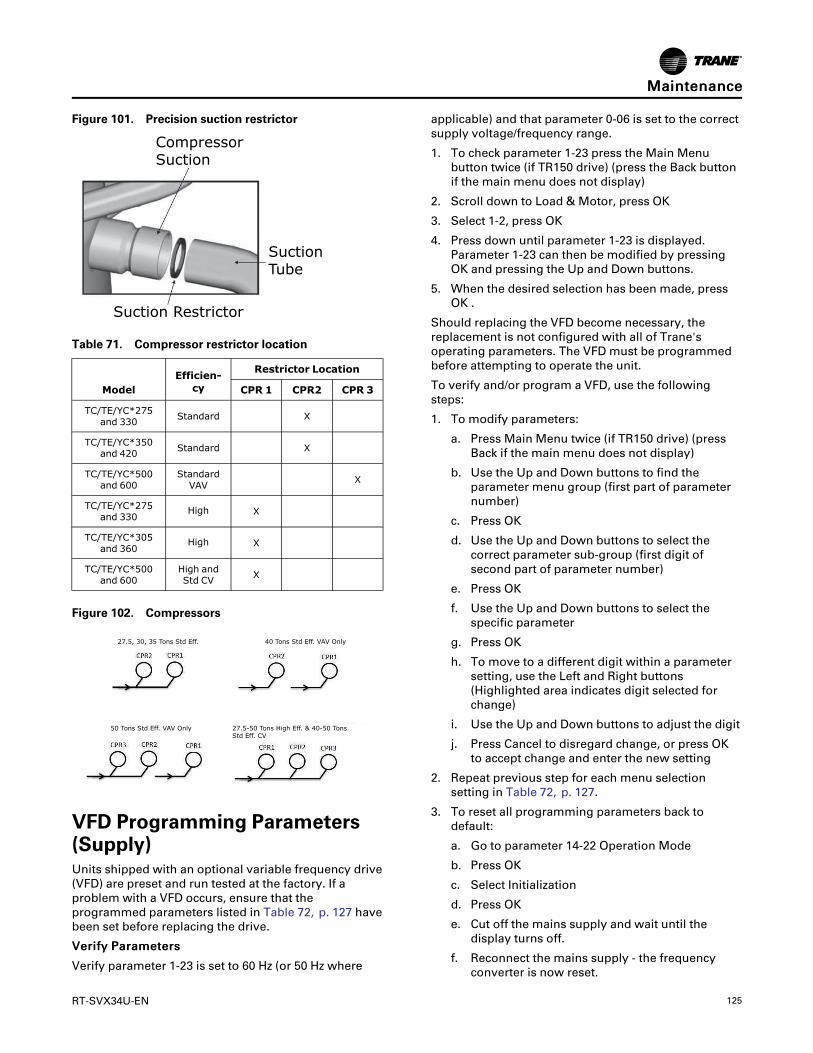
RT-SVX34U-EN 125
Figure 101. Precision suction restrictor
CompressorSuction
SuctionTube
Suction Restrictor
Table 71. Compressor restrictor location
ModelEfficien-cy
Restrictor Location
CPR 1 CPR2 CPR 3
TC/TE/YC*275and 330 Standard X
TC/TE/YC*350and 420 Standard X
TC/TE/YC*500and 600
StandardVAV X
TC/TE/YC*275and 330
High X
TC/TE/YC*305and 360
High X
TC/TE/YC*500and 600
High andStd CV X
Figure 102. Compressors
40 Tons Std Eff. VAV Only27.5, 30, 35 Tons Std Eff.
50 Tons Std Eff. VAV Only 27.5-50 Tons High Eff. & 40-50 TonsStd Eff. CV
VFD Programming Parameters(Supply)Units shipped with an optional variable frequency drive(VFD) are preset and run tested at the factory. If aproblem with a VFD occurs, ensure that theprogrammed parameters listed in Table 72, p. 127 havebeen set before replacing the drive.
VVeerriiffyy PPaarraammeetteerrss
Verify parameter 1-23 is set to 60 Hz (or 50 Hz where
applicable) and that parameter 0-06 is set to the correctsupply voltage/frequency range.
1. To check parameter 1-23 press the Main Menubutton twice (if TR150 drive) (press the Back buttonif the main menu does not display)
2. Scroll down to Load & Motor, press OK
3. Select 1-2, press OK
4. Press down until parameter 1-23 is displayed.Parameter 1-23 can then be modified by pressingOK and pressing the Up and Down buttons.
5. When the desired selection has been made, pressOK .
Should replacing the VFD become necessary, thereplacement is not configured with all of Trane'soperating parameters. The VFD must be programmedbefore attempting to operate the unit.
To verify and/or program a VFD, use the followingsteps:
1. To modify parameters:
a. Press Main Menu twice (if TR150 drive) (pressBack if the main menu does not display)
b. Use the Up and Down buttons to find theparameter menu group (first part of parameternumber)
c. Press OK
d. Use the Up and Down buttons to select thecorrect parameter sub-group (first digit ofsecond part of parameter number)
e. Press OK
f. Use the Up and Down buttons to select thespecific parameter
g. Press OK
h. To move to a different digit within a parametersetting, use the Left and Right buttons(Highlighted area indicates digit selected forchange)
i. Use the Up and Down buttons to adjust the digit
j. Press Cancel to disregard change, or press OKto accept change and enter the new setting
2. Repeat previous step for each menu selectionsetting in Table 72, p. 127.
3. To reset all programming parameters back todefault:
a. Go to parameter 14-22 Operation Mode
b. Press OK
c. Select Initialization
d. Press OK
e. Cut off the mains supply and wait until thedisplay turns off.
f. Reconnect the mains supply - the frequencyconverter is now reset.
MMaaiinntteennaannccee

126 RT-SVX34U-EN
g. Ensure parameter 14-22 Operation Mode hasreverted back to “Normal Operation”.
NNootteess::
• Item 3 resets the drive to the defaultfactory settings. The programparameters listed in Table 72, p. 127will need to be verified or changed asdescribed in Items 1 and 2.
• Some of the parameters listed in thetable are motor specific. Due tovarious motors and efficienciesavailable, use only the values stampedon the specific motor nameplate. Donot use the Unit nameplate values.
• A backup copy of the current setupmay be saved to the LCP beforechanging parameters or resetting thedrive using parameter 0-50 LCP Copy(All to LCP to save all parameters tokeypad and All from LCP to downloadall parameters into drive/replacementdrive).. See LCP Copy in the VFDOperating Instructions for details.
4. Follow the start-up procedures for supply fan in the“Variable Air Volume System” section.
5. After verifying that the VFD(s) are operatingproperly, press the STOP key at the HumanInterface Module to stop the unit operation.
6. Follow the applicable steps in the “Final UnitCheckout” section to return the unit to its normaloperating mode.
If a problem with a VFD occurs, ensure that theprogrammed parameters listed for supply VFD havebeen set before replacing the drive.
MMaaiinntteennaannccee

RT-SVX34U-EN 127
Table 72. Supply fan VFD programming parameters
Menu ID Name FC Unit
Operation/Display
0-01 Language English US
0-03 Regional Settings North America
0-06 (TR150 only) Grid Type
Set to applicable unit powersupply 200-240V/60Hz for 200 &230V/60Hz units; 440-480V/60Hz for 460V/60Hz units; 525-600V/60Hz for 575V/60Hz units;380-440V/50Hz for 380 & 415V/50Hz supply.For IT Grid (noground connections) or corner-grounded Delta power supplysystems, select the applicablevoltage/Hz and IT-Grid or Delta.
0-20 (TR200 only) Display Line 1.1 Small Analog Input 53
0-22 (TR200 only) Display Line 1.3 Small Input Power [hp]
0-40 [Hand on] Key on LCP Disabled
Load and Motor
1-03 Torque Characteristics Variable Torque
1-20 (TR150)1-21(TR200) Motor Power [HP] Per Motor Nameplate HP hp
1-22 Motor Voltage Per Motor Nameplate Voltage V
1-23 Motor Frequency Per Motor Nameplate Hz
1-24 Motor Current Per Motor Nameplate FLA A
1-25 Motor Nominal Speed Per Motor Nameplate RatedSpeed RPM
1-39 Motor Poles 4
1-73 Flying Start Enabled
1-90 Motor Thermal Protection ETR Trip1
Brakes
2-00 DC Hold/Preheat Current 0 %
2-01 DC Brake Current 0 %
2-04 DC Brake Cut In Speed [Hz] 10 Hz
Reference / Ramps
3-03 Maximum Reference 60 Hz
3-16 Reference 2 Source No function
3-17 Reference 3 Source No function
3-41 Ramp 1 Ramp up Time 30 s
3-42 Ramp 1 Ramp Down Time 30 s
Limits / Warnings
4-12 Motor Speed Low Limit [Hz] 35 Hz
4-14 Motor Speed High Limit [Hz] 60 Hz
4-18 Current Limit 100 %
4-19 Max Output Frequency 60 Hz
Digital In/Out
5-12 Terminal 27 Digital Input Coast inverse
5-13 Terminal 29 Digital Input No operation
5-40 Function RelayRelay 1 active No alarm, Relay 2active Motor Running (Relay 1
[160], Relay 2 [5])
MMaaiinntteennaannccee

128 RT-SVX34U-EN
Table 72. Supply fan VFD programming parameters (continued)
Menu ID Name FC Unit
Analog In/Out6-14 Terminal 53 Low Ref./Feedb.
Value 35
6-15 Terminal 53 High Ref./Feedb.Value 60
Special Function
14-01 Switching Frequency 8.0 kHz (drive dependant, set to5kHz if 8kHz not available)
14-11 (TR200 only) Mains Voltage at Mains Fault 391V for 460V 60Hz unit, leaveat default otherwise
14-12 Function at Mains Imbalance Derate
14-20 Reset Mode Automatic reset x 5
14–27 Action at Inverter Fault Warning
14-50 RFI Filter Off
14-60 (TR200 only) Function at OverTemperature Derate
14-61 (TR200 only) Function at Inverter Overload Derate
Note: For 50Hz units parameters 0-06 Grid Type (TR150s only) and 1-23 Motor Freq will need to be set accordingly.
MMaaiinntteennaannccee

RT-SVX34U-EN 129
DiagnosticsThe RTRM has the ability to provide the servicepersonnel with some unit diagnostics and systemstatus information.
Before turning the main power disconnect switch“Off”, follow the steps below to check the Unit Control.All diagnostics and system status information stored inthe RTRM will be lost when the main power is turned“Off”.
WWAARRNNIINNGGLLiivvee EElleeccttrriiccaall CCoommppoonneennttss!!FFaaiilluurree ttoo ffoollllooww aallll eelleeccttrriiccaall ssaaffeettyy pprreeccaauuttiioonnsswwhheenn eexxppoosseedd ttoo lliivvee eelleeccttrriiccaall ccoommppoonneennttss ccoouullddrreessuulltt iinn ddeeaatthh oorr sseerriioouuss iinnjjuurryy..WWhheenn iitt iiss nneecceessssaarryy ttoo wwoorrkk wwiitthh lliivvee eelleeccttrriiccaallccoommppoonneennttss,, hhaavvee aa qquuaalliiffiieedd lliicceennsseedd eelleeccttrriicciiaannoorr ootthheerr iinnddiivviidduuaall wwhhoo hhaass bbeeeenn pprrooppeerrllyy ttrraaiinneeddiinn hhaannddlliinngg lliivvee eelleeccttrriiccaall ccoommppoonneennttss ppeerrffoorrmmtthheessee ttaasskkss..
HIGH VOLTAGE IS PRESENT AT TERMINAL BLOCKHTB1 OR UNIT DISCONNECT SWITCH.
1. Verify that the LED on the RTRM is on. If the LED ison or blinking (2 blinks every 2 seconds). If so, go tostep 3.
2. If the LED is not on, verify that 24 Vac is presentbetween RTRM J1-1 and J1-2. If 24 Vac is present,proceed to Step 3. If 24 Vac is not present, check theunit main power supply, check transformer (TNS1)and fuse. If the LED is not on or blinking yet 24Vacis present, the RTRM has failed and must bereplaced.
3. If the LED is blinking, a diagnostic is present. If theLED is on, certain diagnostics may still be present.Utilizing “System Status/Diagnostics,” p. 129,check the following system status:
• Service status
• Heating status
• Cooling status
4. If any diagnostic is seen, refer to the appropriateDiagnostics section for CV, SZ VAV, or TraditionalVAV units. Once the condition causing thediagnostic is cleared, proceed to the next step.
5. If no diagnostics are present, use one of the TESTmode procedures described in “Test Modes,” p. 67to start the unit. This procedure will allow you tocheck all of the RTRM outputs, and all of theexternal controls (relays, contactors, etc.) that theRTRM outputs energize, for each respective mode.Proceed to the next step.
6. Step the system through all of the available modesand verify operation of all outputs, controls, andmodes. If a problem in operation is noted in any
mode, you may leave the system in that mode forup to one hour while troubleshooting. Refer to thesequence of operations for each mode to assist inverifying proper operation. Make the necessaryrepairs and proceed to the next step.
7. If no abnormal operating conditions appear in thetest mode, exit the test mode by turning the power“Off” at the main power disconnect switch.
8. Refer to the individual component test procedures ifother microelectronic components are suspect.
System Status/DiagnosticsSystem status and/or diagnostics can be observed atthe ZSM, through ICS, or at the unit by using a DCvoltmeter. The LED on the RTRM module does notindicate whether diagnostics are present or not. ThisRTRM LED is an indicator that the RTRM has power,and it pulses during the TEST mode.
Figure 103. Terminal locations
System Status / Diagnostics CheckoutProcedure (DC Voltmeter Required)The method described below to determine unit statusor to see if diagnostics are present assumes the ZoneSensor or NSB panel is not within sight or close by or isnot being used. If a zone sensor is within sighthowever, DC readings need not be taken - just look atthe LED or display and go to STEP 3.
1. Measure and record DC voltage from J6-6(common) to each output: J6-7, J6-8, J6-9, and J6-10.
2. Using the data below, determine if each output isON, OFF, or PULSING.
All voltages are approximate - this is a sensitivecircuit, so the type of voltmeter used, sensorconnections etc. may all slightly affect the reading.
ON = 30Vdc if no NSB or ZSM with LED's isconnected, 25 Vdc if NSB panel (BAYSENS119*) isconnected, 2Vdc if ZSM w/ LED's (BAYSENS110*,BAYSENS021*) is connected.
OFF = 0.75 Vdc regardless of ZSM / NSB connection
PULSING (DIAGNOSTIC PRESENT) = A distinctpulsing from 0.75 Vdc to 30 Vdc will be seen

130 RT-SVX34U-EN
depending on the type of meter used. Some metersmay only pulse between 20 and 30 volts DC.
3. Refer to the data in “What Outputs Mean” sectionto determine course of action.
What Outputs Mean:
HEAT J6-7
• On = system is actively heating
• Off = system is not actively heating
• Pulsing = a diagnostic is present (seeDIAGNOSTICS section).
COOL J6-8
• On = system is actively cooling
• Off = system is not actively cooling
• Pulsing = a diagnostic is present (seeDIAGNOSTICS section).
SYSTEM J6-9
• On = RTRM has power
• Off = RTRM does not have power or has failed
• Pulsing = unit is in the TEST mode
SERVICE J6-10
• On = dirty air filter indication
• Off = normal operation
• Pulsing = a diagnostic is present (seeDIAGNOSTICS section).
NNoottee:: Diagnostics for CV/SZ VAV or VAV units arelisted separately. The same diagnostic mayhave a different meaning depending onwhether the unit has VAV controls or CV/SZVAV controls.
Diagnostics (CV and SZ VAV Units Only)If only one diagnostic is present, refer to that diagnosticlisting below. If more than one diagnostic is present,refer to combination diagnostics such as COOL + HEATas appropriate. On a BAYSENS119*, the display willshow HEAT FAIL or COOL FAIL or SERVICE (or anappropriate combination) if a diagnostic is present. Ifthe unit is using a conventional thermostat, diagnosticsare still available by using a DC voltmeter as describedabove.
HEAT (YC only)• TCO1, TCO2 or TCO3 has opened.
• IGN Module lockout (see gas heat section fortroubleshooting).
• Supply Air Temperature has Failed (SZ VAV Onlywith Modulating Heat).
COOL• Zone temp input (RTRM J6-1) is open, shorted, or
has failed after the RTRM sensed a valid input.
NNoottee:: Since CV units may use a conventionalthermostat, the RTRM will not send adiagnostic if a zone sensor is not attachedwhen power is applied to the unit. Also, theRTRM ignores a zone sensor if it is attachedto a powered-up unit. (after a brief time-out).Therefore, always reset power after installinga mechanical ZSM to terminals RTRM J6-1through J6-5.
All units configured for SZ VAV will blink theCool indicator if there is a Zone Temp. inputfailure because a valid Zone Temperaturereading is required for all SZ VAV operation.
• Cooling and heating setpoint inputs are both open,shorted, or failed, but the unit has a valid zone tempinput.
• Programmable ZSM (BAYSENS119*) has failed tocommunicate after successful communication hasoccurred.
• CC1 or CC2 24 VAC control circuit has opened 3times during a cooling mode. Check CC1, CC2 coilsor any controls in series with the coils (windingthermostat, HPC, circuit breaker auxiliary contacts).
• LPC 1 or LPC 2 has opened during the 3 minuteminimum “on” time during 4 consecutivecompressor starts. Check LPC 1 circuit bymeasuring voltage from RTRM J1-8 to chassisground. Check LPC 2 circuit by measuring voltagefrom RTRM J3-2 to chassis ground. If 24 VAC is notpresent, the circuit is open. 24 VAC should bepresent at these terminals at all times.
• Discharge air sensor (DTS) input is open, shorted,or has failed.
SERVICEThe supply fan proving switch (FFS) has failed to closewithin 40 seconds after the fan starts or has closedduring fan operation.
HEAT + COOL• The Emergency Stop input (LTB1-5 and LTB1-6) is
open. Check this input at the RTRM by measuringvoltage from RTRM J1-12 to chassis ground. 24VAC should be present whenever the EmergencyStop input is closed.
• Outdoor air sensor (OAS) input is open, shorted, orhas failed.
HEAT + COOL + SERVICE• Smoke Detector input active.
• Supply Air Temperature Failure on units withmodulating hot gas reheat
• Entering Evaporator Temperature Failure on unitswith modulating hot gas reheat.
• RTDM Communication Failure on units withmodulating hot gas reheat.
DDiiaaggnnoossttiiccss

RT-SVX34U-EN 131
Diagnostics (VAV only)If only one diagnostic is present, refer to thatdiagnostic. If more than one diagnostic is present, referto combination diagnostics such as COOL + HEAT asappropriate. On a BAYSENS119*, the display will showHEAT FAIL or COOL FAIL or SERVICE (or an appropriatecombination) if a diagnostic is present.
HEAT (YC only)• TCO1, TCO2, or TCO3 has opened.
• IGN Module lockout (see gas heat section fortroubleshooting).
COOL• Discharge air sensor (DTS) is open, shorted, or has
failed.
• Zone temp input (RTRM J6-1) is open, shorted, orfailed during an unoccupied mode. If the unit has adefault mode input (jumper from RTRM J6-2 toRTRM J6-4, a valid zone temp input is needed forunoccupied heating, MWU and DWU.
• CC1 or CC2 24 VAC control circuit has opened 3times during a cooling mode. Check CC1, CC2 coilsor any controls in series with the coils (windingthermostat, HPC, circuit breaker auxiliary contacts).
• LPC 1 or LPC 2 has opened during the 3 minuteminimum “on” time during 4 consecutivecompressor starts. Check LPC 1 circuit bymeasuring voltage from RTRM J1-8 to chassisground. Check LPC 2 circuit by measuring voltagefrom RTRM J3-2 to chassis ground. If 24 VAC is notpresent, the circuit is open. 24 Vac should present atthese terminals at all times.
SERVICEThe supply fan proving switch (FFS) has failed to openwithin 40 seconds after the fan starts or has closedduring fan operation.
COOL + SERVICEStatic Pressure Transducer output voltage at RTAM J1-3 is less than 0.25Vdc. The transducer output is open,shorted, or the transducer is reading a negative supplyair pressure.
HEAT + COOL• The Emergency Stop input (TB1-5 and TB1-6) is
open. Check this input at the RTRM by measuringvoltage from RTRM J1-12 to chassis ground. 24 Vacshould be present whenever the Emergency Stopinput is closed.
• Outdoor air sensor (OAS) input is open, shorted, orhas failed.
HEAT + COOL + SERVICE• Static Pressure High Duct Static Trip. The static
pressure has exceeded 3.5" W.C. three consecutivetimes.
• Smoke Detector input active.
• Supply Air Temperature Failure on units withmodulating hot gas reheat.
• Entering Evaporator Temperature Failure on unitswith modulating hot gas reheat.
• RTDM Communication Failure on units withmodulating hot gas reheat.
Resetting Cooling and Ignition LockoutsCooling Failures and Ignition Lockouts are reset in anidentical manner. Method 1 explains resetting thesystem from the space; Method 2 explains resetting thesystem at the unit.
NNoottee:: Before resetting Cooling Failures and IgnitionLockouts check the Failure Status Diagnostics bythe methods previously explained. Diagnosticswill be lost when the power to the unit isdisconnected.
Method 1To reset the system from the space, turn the “Mode”selection switch at the zone sensor to the “Off”position. After approximately 30 seconds, turn the“Mode” selection switch to the desired mode, i.e. Heat,Cool or Auto.
Method 2To reset the system at the unit, cycle the unit power byturning the disconnect switch “Off” and then “On”.
Lockouts can be cleared through the buildingmanagement system. Refer to the buildingmanagement system instructions for moreinformation.
Zone Temperature Sensor (ZSM) ServiceIndicatorThe ZSM SERVICE LED is used to indicate a cloggedfilter, an active Smoke Detector, or a Fan Failure trip.
Clogged Filter SwitchThis LED will remain on 2 minutes after the NormallyOpen switch is closed. The LED will be turned offimmediately after resetting the switch (to the NormallyOpen position), or any time that the IDM is turned off.
If the switch remains closed, and the IDM is turned on,the SERVICE LED will be turned on again after the 2(±1) minutes.
This LED being turned on will have no other affect onunit operation. It is an indicator only.
DDiiaaggnnoossttiiccss

132 RT-SVX34U-EN
Smoke Detector SwitchThe LED will flash anytime that the N.O. SmokeDetector input is closed and will be reset anytime thatthe input is returned to its N.O. state. During an ActiveSmoke Detector trip the unit will be shut down.
Fan Failure SwitchThe LED will flash 40 seconds after the fan is turned“On” if the Fan Proving Switch is not made. This LEDwill remain flashing until the unit is reset by meansexplained above. If the “Fan Failure” switch opens forat least 40 seconds during fan operation (indicating afan failure) the unit will stop.
Condensate Overflow SwitchWhen the condensate overflow switch is closed, a drainpan overflow condition is indicated and it will shut unitoperations down.
RTRM Zone Sensor Module (ZSM) TestsNNoottee:: These procedures are not for programmable or
digital models and are conducted with the ZoneSensor Module electrically removed from thesystem.
Table 73. Zone Sensor Module (ZSM) terminalidentification (constant volume only)
Terminal #Terminal I.
D. Terminal #Terminal I.
D.
J6-1 ZTEMP J6-6 LED COMMON
J6-2 SIGNALCOMMON J6-7 HEAT LED
J6-3 CSP* J6-8 COOL LED
J6-4 MODE J6-9 SYS ON LED
J6-5 HSP J6-10 SERVICE LED
Test 1: Zone Temperature Thermistor (ZTEMP)This component is tested by measuring the resistancebetween terminals 1 and 2 on the Zone TemperatureSensor. The following are some typical indoortemperatures, and corresponding resistive values.
Table 74. Resistance values
Zone or SetPoint
TemperatureNominal ZTEMPResistance
Nominal CSP orHSP Resistance
50° F 19.9 K-Ohms 889 Ohms
55° F 17.47 K-Ohms 812 Ohms
60° F 15.3 K-Ohms 695 Ohms
65° F 13.49 K-Ohms 597 Ohms
70° F 11.9 K-Ohms 500 Ohms
75° F 10.50 K-Ohms 403 Ohms
80° F 9.3 K-Ohms 305 Ohms
Table 74. Resistance values (continued)
Zone or SetPoint
TemperatureNominal ZTEMPResistance
Nominal CSP orHSP Resistance
85° F 8.25 K-Ohms 208 Ohms
90° F 7.3 K-Ohms 110 Ohms
Test 2: Cooling Set Point (CSP) and Heating SetPoint (HSP)The resistance of these potentiometers are measuredbetween the following ZSM terminals. Refer to thechart above for approximate resistances at the givenset points.
CSP = Terminals 2 and 3
Range = 100 to 900 Ohms approximate
HSP = Terminals 2 and 5
Range = 100 to 900 Ohms approximate
Test 3: SystemMode and Fan SelectionThe combined resistance of the Mode selection switchand the Fan selection switch can be measured betweenterminals 2 and 4 on the ZSM. The possible switchcombinations are listed below with their correspondingresistance values.
Table 75. Nominal resistance
VAVSystemSwitch
CV SystemSwitch
CV FanSwitch
NominalResistance
OFFOFF AUTO 2.3 K-Ohms
COOL AUTO 4.9 K-Ohms
AUTO
AUTO AUTO 7.7 K-Ohms
OFF ON 11.0 K-Ohms
COOL ON 13.0 K-Ohms
AUTO ON 16.0 K-Ohms
HEAT AUTO 19.0 K-Ohms
HEAT ON 28.0 K-Ohms
Test 4: LED Indicator Tests (SYS ON, HEAT, COOL& SERVICE)• MMeetthhoodd 11:: Testing the LED using a meter with
diode test function. Test both forward and reversebias. Forward bias should measure a voltage dropof 1.5 to 2.5 volts, depending on your meter.Reverse bias will show an over load, or open circuitindication if LED is functional.
• MMeetthhoodd 22:: Testing the LED with an analogOhmmeter. Connect Ohmmeter across LED in onedirection, then reverse the leads for the oppositedirection. The LED should have at least 100 timesmore resistance in reverse direction, as comparedwith the forward direction. If high resistance in both
DDiiaaggnnoossttiiccss

RT-SVX34U-EN 133
directions, LED is open. If low in both directions,LED is shorted.
• MMeetthhoodd 33:: Testing the LED with an analogOhmmeter. Connect Ohmmeter across LED in onedirection, then reverse the leads for the oppositedirection. The LED should have at least 100 timesmore resistance in reverse direction, as comparedwith the forward direction. If high resistance in bothdirections, LED is open. If low in both directions,LED is shorted.
NNoottee:: Measurements should be made from LEDcommon (ZSM terminal 6 to respective LEDterminal). Refer to the Zone Sensor Module(ZSM) Terminal Identification table at thebeginning of this section.
Programmable & Digital Zone Sensor Test
Testing serial communication voltage1. Verify 24 VAC is present between terminals RTRM
J6-14 and RTRM J6-11.
2. Disconnect wires from RTRM J6-11 and RTRM J6-12. Measure the voltage between RTRM J6-11 andRTRM J6-12; it should be approximately 32 Vdc.
3. Reconnect wires to terminals RTRM J6-11 andRTRM J6-12. Measure voltage again between RTRMJ6-11 and RTRM J6-12, voltage should flash highand low every 0.5 seconds. The voltage on the lowend will measure about 19 Vdc, while the voltageon the high end will measure from approximately24 to 38 Vdc.
4. Verify all modes of operation, by running the unitthrough all of the steps in “Test Modes,” p. 67.
5. After verifying proper unit operation, exit the testmode. Turn the fan on continuously at the ZSM, bypressing the button with the fan symbol. If the fancomes on and runs continuously, the ZSM is good.If you are not able to turn the fan on, the ZSM isdefective.
ReliaTel Refrigeration Module (RTRM)
Default Chart - CV and SZ VAV UnitsIf the RTRM loses input from the building managementsystem, the RTRM will control in the default mode afterapproximately 15 minutes. If the RTRM loses theHeating and Cooling Setpoint input from thepotentiometers, the RTRM will control in the defaultmode instantaneously. The temperature sensingthermistor in the Zone Sensor Module for CVapplications is the only component required for the“Default Mode” to operate.
Table 76. Constant volume and single zone VAVdefault operations
Component orFunction Default Operation
Cooling Setpoint(CSP) 74°F
Heating Setpoint(HSP) Economizer 71°F Normal Operation
EconomizerMinimum Position
Normal Operation
Mode Normal operation, or auto if ZSMmodeswitch has failed
Fan Normal operation, or continuous if fanmode switch on ZSM has failed
Night Setback ModeDisabled - Used with Integrated
Comfort™ System and ProgrammableZSM’s only
Supply AirTempering
Disabled - Used with IntegratedComfort™ Systems only
DA Cool Setpoint 50ºF (SZ VAV Only)
DA Heat Setpoint 100ºF (SZ VAV Only)
Default Chart - VAV UnitsIf the RTRM loses input from the building managementsystem, the RTRM will control in the default mode afterapproximately 15 minutes. For VAV units, a “shorted”mode input is the only input required for the “DefaultMode” to operate. If the RTRM loses setpoint inputsfrom the RTAM due to remote setpoint input failure,the RTRM will use default setpoint inputs as defined inthe default chart for VAV units.
Table 77. Variable air volume default operation
Component or Function Default Operation
Supply Air Cooling Setpoint Failure 55° F
Supply Air Reset Setpoint Failure Disable Reset
Supply Air Reset Amount Disable Reset
Supply Air Static
Setpoint Failure 0.5 IWC
Supply Air Static
Deadband Failure 0.5 IWC
Morning Warm-Up
Setpoint Failure Disable MWU and DWU
Mode Failure “Open “Unit Mode “Off”
Mode Failure “Shorted “Unit Mode “Auto”
DDiiaaggnnoossttiiccss

134 RT-SVX34U-EN
Economizer Actuator (ECA/RTEM) Test ProceduresEconomizer Fault Detection andDiagnosticsFault Detection of the Outdoor Air Damper will beevaluated based on the commanded position of thedamper actuator compared to the feedback positionfrom the damper actuator. The damper is commandedto a position based on a 2-10 VDC signal. If the damperposition is outside of ±10% of the commandedposition, a diagnostic is generated.
NNoottee:: Only one diagnostic will be active at any giventime.
Unit Not Economizing When it Should BeThe unit is operating in cooling mode, economizing isenabled and/or mechanical cooling is enabled. If thecommanded economizer position is greater than thecurrent economizer feedback position +10% for 5continuous minutes, a ‘Unit Not Economizing When itShould Be’ diagnostic is generated.
Unit Economizing When it Should Not BeThe unit is operating in cooling mode, economizing isenabled and/or mechanical cooling is enabled. If thecommanded economizer position is less than thecurrent economizer feedback position -10% for 5continuous minutes, a ‘Unit Economizing When itShould Not Be’ diagnostic is generated.
Outdoor Air Damper Not ModulatingIf the unit is operating in ventilation only mode - notattempting to economize - and the commandeddamper position is greater than the current damperfeedback position +10% for 5 continuous minutes, a‘Outside Air Damper Not Modulating’ diagnostic isgenerated.
Excessive Outdoor AirIf the unit is operating in ventilation only mode - notattempting to economize - and the commandeddamper position is less than the current damperfeedback position -10% for 5 continuous minutes, a‘Excessive Outdoor Air’ diagnostic is generated.
Mixed Air Temperature Low Limit DiagnosticIn all conditions on all ReliaTel controlled units, if theMixed Air Temperature falls below 45°F, the ‘Mixed AirTemperature Low Limit’ diagnostic is active and theeconomizer actuator will close to the active minimumposition. On Title 24 compliant units, ReliaTel will setan Auto-Reset Diagnostic to be used by BAS and TD5when the Mixed Air Temperature Low Limit is active.
The RTEM will revert to normal operation when theMixed Air Temperature rises above 48°F. The
Diagnostic will be reset when the Mixed AirTemperature Low Limit is inactive.
Verify Economizer Status by EconomizerActuator (ECA/RTEM)LED indicator:
• OFF: No Power or Failure
• ON: Normal, OK to Economize
• Slow Flash: Normal, Not OK to Economize
• Fast Flash: ¼ Second ON/2 Seconds OFFCommunications Failure
• 1 Flash: Actuator Fault
• 2 Flashes: CO2 Sensor out of range
• 3 Flashes: RA Humidity Sensor out of range
• 4 Flashes: RA Temp Sensor out of range
• 6 Flashes: OA Humidity Sensor out of range
• 7 Flashes: OA Temp Sensor out of range
• 8 Flashes: MA Temp Sensor out of range
• 9-11 Flashes: Internal ECA failure
NNoottee:: The Outdoor Air Sensor (OAS) is also usedfor the economizer operation. It is connectedto the RTRM.
Test 1: VoltageDisconnect the OAS from the wires in the return airsection. Check the voltage at the wires going to theRTRM. The voltage should be 5 (± 0.25) Vdc.
Check the resistance at the wires going to the OAS andmeasure the temperature at the OAS location. Usingthe Temperature versus Resistance chart, verify theaccuracy of the OAS.
If voltage specified is not present, the ECA has failed.
Test 2: Testing the ECA sensors1. Testing the Mixed Air Sensor (MAS). Disconnect the
cable connected to MAT on the ECA. Using theThermistor Resistance / Temperature Chart (Table18, p. 39):
a. Measure the resistance of the sensor betweenthe connector terminals P23-1 and P23-2.
b. Measure the temperature at the MAS location.Using the Temperature versus Resistance chart,verify the accuracy of the MAF.
Replace the sensor if it is out of range.
2. Testing the Return Air Sensor (RAS). Disconnect thecable connected to RAT on the ECA. Using theThermistor Resistance / Temperature Chart (Table18, p. 39):
a. Measure the resistance of the sensor betweenthe connector terminals P10-1 and P10-2.
b. Measure the temperature at the RAS location.
DDiiaaggnnoossttiiccss

RT-SVX34U-EN 135
Using the Temperature versus Resistance chart,verify the accuracy of the RAS.
Replace the sensor if it is out of range.
3. Testing the Humidity Sensors.
a. Return Humidity Sensor (RHS). Leave thesensor connected to the ECA, and measure theoperating current. The normal current range is 4to 20 mA (milliampere). Replace the sensor if itis out of range.
b. Outdoor Humidity Sensor (OHS). Leave thesensor connected to the ECA, and measure theoperating current. The normal current range is 4to 20 mA (milliampere). Replace the sensor if itis out of range.
NNoottee:: Both the RHS and the OHS are polaritysensitive. Verify that the polarity is correctbefore condemning the sensor. Incorrectwiring will not damage any of the controls,but they will not function if wiredincorrectly.
ReliaTel Air Module (RTAM)Tests
WWAARRNNIINNGGLLiivvee EElleeccttrriiccaall CCoommppoonneennttss!!FFaaiilluurree ttoo ffoollllooww aallll eelleeccttrriiccaall ssaaffeettyy pprreeccaauuttiioonnsswwhheenn eexxppoosseedd ttoo lliivvee eelleeccttrriiccaall ccoommppoonneennttss ccoouullddrreessuulltt iinn ddeeaatthh oorr sseerriioouuss iinnjjuurryy..WWhheenn iitt iiss nneecceessssaarryy ttoo wwoorrkk wwiitthh lliivvee eelleeccttrriiccaallccoommppoonneennttss,, hhaavvee aa qquuaalliiffiieedd lliicceennsseedd eelleeccttrriicciiaannoorr ootthheerr iinnddiivviidduuaall wwhhoo hhaass bbeeeenn pprrooppeerrllyy ttrraaiinneeddiinn hhaannddlliinngg lliivvee eelleeccttrriiccaall ccoommppoonneennttss ppeerrffoorrmmtthheessee ttaasskkss..
Test 1: Testing the Variable FrequencyDrive (VFD) Output1. Using the procedure for VAV applications outlined
in “Test Modes,” p. 67, step the unit to the first test(Step 1). Verify that 10 Vdc is present betweenterminals J4-2 and J4-1.
NNoottee:: If voltage is incorrect, verify RTAM DIP switchsettings.
2. If voltage to the VFD is not present, verify that thewires are properly connected between the RTRM orCOMM (Communications Module) and the RTAM.
If Step 2 checks out and the voltage is still notpresent at the VFD output, replace the RTAM.
Test 2: Testing the Static PressureTransducer (SPT) Input1. With main power to the unit turned “Off”,
disconnect all of the tubing to the Static PressureTransducer.
2. With the system MODE “Off”, apply power to theunit and measure the voltage between J1-4 and J1-1 on the RTAM. The voltage should beapproximately 5 Vdc. If not, check the wiringbetween the RTRM and the RTAM. If the wiringchecks good, replace RTAM.
3. Measure the voltage between J1-3 and J1-1 on theRTAM. The voltage should be approximately 0.25Vdc. If not, check the wiring between the RTAM andthe SPT. If the wiring checks good, replace the SPT.
4. Apply 2.0" w.c. pressure to the HI port on the staticpressure transducer (SPT). Measure the voltagebetween J1-1 and J1-3. The voltage should be 1.75(± 0.14) Vdc. If not, replace the SPT.
NNoottee:: The SPT is susceptible to interference fromVFD’s. Make sure the SPT is mounted onplastic standoffs and is not touching anysheet metal.
Test 3: Testing the VAV SetpointPotentiometersTurn the main power disconnect switch “OFF”. Checkeach potentiometer listed in the table below bymeasuring resistance. These potentiometers are builtinto the RTAM and are not replaceable.
Static PressureSetpoint
0-560 ohms(Approximate) RTAM J7-1,2
Static Pressure Deadband
0-560 ohms(Approximate) RTAM J7-7,8
Reset Setpoint 0-560 ohms(Approximate) RTAM J7-11,12
Reset Amount0-560 ohms(Approximate) RTAM J7-5,6
Morning Warm-upSetpoint
0-560 ohms(Approximate) RTAM J7-9,10
Supply Air CoolingSetpoint
0-560 ohms(Approximate) RTAM J7-3,4
Supply Air HeatingSetpoint
0-560 ohms(Approximate) RTAM J7-13,14
Test 4: Testing the VFD1. Verify that the keypad in control box is powered. If
not, check the power wires to the VFD and theKeypad cable.
2. Using the procedure described in “Test Modes,” p.67, verify that the fan starts and the speed increasesuntil the SA Pressure reaches the “Setpoint” onVAV Setpoint panel. If the fan does not start, checkfor “Fault Conditions” on the VFD Keypad.
3. If no “Fault Conditions” exist and the fan startedbut did not ramp up to speed, verify the “speedreference voltage” output from the RTAM betweenterminals J4-1 and J4-2.
DDiiaaggnnoossttiiccss

136 RT-SVX34U-EN
4. If no “Fault Conditions” exist and the fan did notstart, verify that the Fan relay is energized and theVFD “Start Command” is properly wired from theFan relay, (24 volts on the Logic Input 2 (LI2)terminal). Verify that the jumper between +24V andthe LI1 terminal is properly connected.
5. Verify that 115 Vac is present from the transformeron the VFD assembly panel.
NNootteess::
• Begin troubleshooting by checking forany diagnostics. See System Status/Diagnostics.
• Always verify the unit is operating in theproper “MODE” when troubleshooting.
ReliaTel Air Module (RTOM)TestsTest 1: Testing the Variable FrequencyDrive (VFD) Output1. Using the “Test Modes,” p. 67 procedure for SZ
VAV applications in the “Startup,” p. 42 section,step the unit to the fourth test (Step 4). Verify that10 Vdc is present between terminals J11-2 and J11-1.
2. If the voltage to the VFD is not present, verify thatthe wires are properly connected between theRTRM or COMM (Communications Module) and theRTOM.
3. If Step 2 checks out and the voltage is still notpresent at the VFD output, replace the RTOM.
Test 2: Testing the VFD1. Verify that the keypad in control box is powered. If
not, check the power wires to the VFD and theKeypad cable.
2. Using the “Step Test Mode” procedure described inthe “Startup,” p. 42 section, step the unit to thefourth test (Step 4). Verify that the fan starts and thespeed increases. If the fan does not start, check for“Fault Conditions” on the VFD Keypad.
3. If no “Fault Conditions” exist and the fan startedbut did not ramp up to speed, verify the “speedreference voltage” output from the RTOM between
terminals J11-1 and J11-2.
4. If no “Fault Conditions” exist and the fan did notstart, verify that the Fan relay is energized and theVFD “Start Command” is properly wired from theFan relay, (24 volts on the Logic Input 2 (LI2)terminal). Verify that the jumper between +24V andthe LI1 terminal is properly connected.
5. Verify that 115 Vac is present from the transformeron the VFD assembly panel.
NNootteess::
• Begin troubleshooting by checking forany diagnostics. See System Status/Diagnostics.
• Always verify the unit is operating in theproper “MODE” when troubleshooting.
Compressor—Blink CodesThe CSHN*** large commercial compressors comeequipped with a compressor protection device capableof detecting phase reversal, phase loss, and phaseunbalance. The compressor protection device uses agreen and red LED to indicate the compressor status. Asolid green LED denotes a fault-free condition; ablinking red LED indicates an identifiable faultcondition.
NNoottee:: If the compressor has tripped, the resistance willbe 4500 ohms or greater; when reset, it will beless than 2750 ohms.
The blink code consists of different on / off times of thered LED which is repeated continuously until either thefault is cleared or until power is cycled.
Table 78. Blink codes
Fault LED on LED off LED on LED off
PTC overheat orPTC reset delayactive
shortblink
longblink
shortblink
longblink
Phase loss longblink
longblink
longblink
longblink
Incorrect phasesequence
shortblink
shortblink
shortblink
longblink
DDiiaaggnnoossttiiccss

RT-SVX34U-EN 137
TroubleshootingTable 79. Troubleshooting
SYMPTOM PROBABLE CAUSE RECOMMENDED ACTION
A. Unit will not operate. No Heat, NoCool or No Fan operation.
1. No power to the Unit. 1. Check line voltage at service disconnect.
2. No power to the RTRM. 2. Check for 24 VAC at RTRM J1-1 to system ground.
3. Zone Sensor Module (ZSM) is defective or MODEcircuit is open. (VAV only)
3. See Zone Sensor Module (ZSM) Test Procedures orshort MODE input on VAV units.
4. RTRM is defective.4. If 24 VAC is present at the RTRM J1-1 to ground,the LED on the RTRM should be on. If the LED is notlit, replace the RTRM.
5. Supply Fan Proving (FFS) switch has opened. 5. Check the IDM and belts, replace as necessary.
6. Emergency Stop input is open. 6. Check the Emergency Stop input.
CV or SZ VAV Units only
B. Unit will not Heat or Cool, but theFan switch operates.
1. Zone Sensor Module (ZSM) is defective. 1. Refer to the Zone Sensor Module (ZSM) TestProcedures.
2. Problem in (ZSM) wiring.2. Disconnect the ZSM wiring at RTRM and test thewires using the Zone Sensor Test Procedures tolocate any wiring problems.
3. RTRM is defective.3. Disconnect the ZSM wiring at the RTRM andperform the Zone Sensor Module (ZSM) TestProcedures. If within range, replace RTRM.
CV, SZ VAV or VAV (Unoccupied)
C. Unit heats and cools, but will notcontrol to set point.
1. Zone Sensor Module (ZSM) is defective. 1. Refer to the Zone Sensor Module (ZSM) TestProcedures.Refer to the Default Chart.
2. Thermometer on the ZSM out of calibration. 2. Check and calibrate the thermometer.
D. CPR1 will not operate, ODM's willoperate.
1. Compressor failure. 1. Test compressor, mechanically and electrically.Replace if necessary.
2. Wiring, terminal, or mechanical CC1 contactorfailure.
2. Check wires, terminals and CC1. Repair or replaceif necessary.
3. LPC1 has tripped 3. Leak check, repair, evacuate and recharge asnecessary. Check LPC1 operation.
E. CPR1 operates, ODM's will notoperate.
1. ODM has failed. 1. Check ODM's, replace if necessary.
2. ODM capacitor(s) has failed. 2. Check ODM capacitors, replace if necessary.
3. Wiring, terminal, or mechanical CC1 or CC2contactor failure.
3. Check wires, terminals,CC1 and CC2. Repair orreplace if necessary.
4. ODF 20 or 34 relay has failed4.Check for proper voltage and contact closure.ODF20 and 34 have a 24 VAC holding Coil. If voltageis present, replace relay.
5. RTRM is defective5. Locate the P3 connector on the RTRM. Check for24 VAC at terminal P3-6. If 24 VAC is not present,replace RTRM.
F. CPR1 and ODM1 will not operate.
1. No power to CC1 coil. Possible Cool Failure 1. Check wiring, terminals and applicable controls(CCB1, HPC1, TDL1, WTL1, LPC1)
2. CC1 coil defective. Cool Failure Indicated. 2. Check CC1 coil. If open or shorted, replace CC1.
3. CC1 contacts defective. 3. If 24 VAC is present at CC1coil, verify contactclosure.
4. RTRM is defective.
4. If 24 VAC is not present at CC1 coil, reset the CoolFailure by cycling the main power disconnect switch.Verify system MODE is set for cooling operation. If nocontrols have opened, and CC1 will not close, replaceRTRM.
5. LPC1 has tripped 5. Leak check, repair, evacuate, and recharge asnecessary. Check LPC1 operation.
DDiiaaggnnoossttiiccss

138 RT-SVX34U-EN
Table 79. Troubleshooting (continued)
SYMPTOM PROBABLE CAUSE RECOMMENDED ACTION
G. ODM 3 and/or 4 will not cycle.
1. OAS has failed.1. Perform OAS Resistance/Temperature check.Replace if necessary.
2. ODM3 and/or 4 capacitor has failed. 2. Check ODM capacitor, replace if necessary.
3. Wiring, terminal, or CC2 contactor failure. 3. Check wires, terminals, and CC2. Repair or replaceif necessary.
4. ODM3 and/or 4 has failed. 4. Check ODM, replace if necessary.
5. RTRM is defective. 5. Replace RTRMmodule
6. ODF20 has failed.6. Check for proper voltage and contact closure.ODF20 relay has a 24 VAC holding coil. If voltage ispresent, replace relay.
H. CPR2 and 3 (if applicable) will notoperate.
1. No power to CC2 and/or 3 coil. Cool FailurePossible.
1. Check wiring, terminals and applicable controls(CCB2, CCB3, HPC2, LPC2, WTL2, WTL3, TDL2 &TDL3)
2. CC2 and/or 3 coil defective. Cool Failure Indicated. 2. Verify integrity of CC2 and/or 3 coil windings. Ifopen or shorted replace CC2 and/or CC3.
3. CC2 and/or 3 contacts defective. 3. If 24 VAC is present at CC2 and/or 3 coil, replacerelay.
4. RTRM is defective.
4. 24 VAC is not present at CC2 and/or 3 coil. Resetthe Cool Failure by cycling the service disconnect.Place the unit into Cool Stage 2 Mode, step 4 forconstant Volume or step 6 for variable air volume, toinsure CPR2 and 3 Compressor operation. Checkinput devices in #1 & #2 above, if no controls haveopened, and CC2 and/or 3 will not close, replaceRTRM.
5. DLT2 and DLT3 has tripped.4. Check for leaks, Open wire connections, Losequick connect terminals, TDL2 and TDL3 resistancecheck.
I. Indoor motor (IDM) will not operate
1. IDM has failed. 1. Check IDM, replace if necessary.
2. Wiring, terminal, or contactor failure. 2. Check wiring, terminals and F contactor. Repair orreplace wiring, terminals, or fan contactor F.
3. ZSM is defective.3. Place unit in test mode. If the fan operates in thetest mode, test the ZSM using the appropriate testprocedures.
4. RTRM is defective.4. Check the RTRM fan output. Locate P2-1 on theRTRM. Measure voltage to ground. If 24 VAC is notpresent on a call for fan, replace the RTRM.
5. Supply Fan Proving (FFS) switch has opened. 5. Check FFS and belts, repair or replace ifnecessary.
J. No Heat (YC’s only) CFM will notrun, IP warms up, GV is energized
1. CFM has failed. 1. Check CFM, replace if necessary.
2. CFM capacitor has failed. 2. Disconnect BROWN wires from capacitor, test, andreplace if necessary.
3. Wiring, or terminal failure. 3. Check wiring, and terminals. Repair, or replace ifnecessary.
4. TNS3 and/or 4 has failed. (460/575 V units only)4. Check for 230 VAC at TNS3 and/or 4 secondary,between Y1 and Y2. If 230 VAC is not present,replace TNS3 and/or 4.
5. Modulating gas is not configured properly. 5. Check RTOM wiring and control board softwareversions.
K. No Heat (YC’s only) CFM runs, GVenergizes, IP does not warm up.
1. TNS3 and/or 4 has failed.1. Check for 115 VAC at TNS3 and/or 4 secondary,between X1 and X2. If 115 VAC is not present,replace TNS3 and/or 4.
2. Wiring or terminal failure. 2. Check wiring and terminals. Repair or replace ifnecessary.
3. IP has failed.
3. With 115 VAC applied to IP, warm up should takeplace. Cold resistance of IP should be a minimum of50 Ohms. Nominal current should be 2.5 to 3.0Amps.
L. No Heat (YC’s only) GV does notenergize, CFM runs, IP warms up
1. Wiring or terminal failure.1. Verify presence of 24 VAC between IGN J1-7terminal to ground, if not present, check wiring andterminals. Repair or replace if necessary.
2. GV has failed, in two stage units2. Measure voltage between TH and TR on the gasvalve (GV). If 24 VAC is present and the GV will notopen, replace the GV.
3. Pressure switch failure, in mod heat units3. In mod heat units, verify the pressure switch iswired correctly. If wired correctly, verify operation ofpressure switch.
DDiiaaggnnoossttiiccss

RT-SVX34U-EN 139
Table 79. Troubleshooting (continued)
SYMPTOM PROBABLE CAUSE RECOMMENDED ACTIONM. Low Heat Capacity IntermittentHeat. (YC’s only) CFM runs in LO or HIspeed only, or; may not operate at allin one speed or the other.
CFM has failed. Check CFM, test LO and HI speed windings.
N. No Heat (YC’s only) “Fan” selectionswitch on the ZSM is in the “AUTO”position and the fan runscontinuously.
TCO2 has opened. Heat Failure Indicated.
System Status Failure Diagnostic. Place the unit inthe Heating Test Mode, steps 6 & 7 for constantvolume or step 8 & 9 for variable air volume andcheck the complete heating system for failure. Makenecessary repairs or adjustments to the unit.
O. No Heat (TE's only) Electric heatwill not operate.
1. Heater contactor(s) have failed.1. Check for 24 VAC at AH, BH,CH, and DH contactorcoils. If 24 VAC is present on a call for heat, and thecontacts do not close, the contactor has failed.
2. Heater element temperature limit(s) is open.
2. Check line voltage between the elementtemperature limit terminals located in heat section.If line voltage is present, the limit is open. Repairheating unit, or replace limit(s) as needed.
3. Wiring or terminal failure. 3. Check for wiring, or terminal failure in control andpower circuit. Repair or replace if necessary.
4. Heater Element(s) has failed. 4. Check element and circuit integrity. Repair orreplace as necessary. Replace open elements.
5. RTRM is defective.
5. Check RTRM heat outputs. “First stage”, locate P2connector, connected to J2 on the RTRM. Locate wire65E at terminal P2-9, measure between 65E andground. If 24 VAC is present, repeat #3 above. If 24Vac is not present, the RTRM has failed. “Secondstage”, Locate 67B wire at terminal P2-8, measurebetween 67B and ground. 24 Vac should be present.If 24 Vac is not present, the RTRM has failed.
P. Evaporator coil freezes up duringlow ambient operation.
1. System low on refrigerant charge. 1. Leak check, repair, evacuate, and rechargesystem as necessary.
2. System low on air flow. 2. Check return air for obstruction or dirty filters.Check fan wheels, motors, and belts.
3. Outdoor Air Sensor (OAS) has Failed.
3. Check OAS at connector P8 by disconnecting P8from J8 on the RTRM. Check resistance between P8-1and P8-2, refer to the Resistance versusTemperature chart. Replace sensor if necessary.
4. Frostat™ has Failed 4. Check Frostat Switch
Q. Economizer will not operate.
1. Economizer connector not plugged into unit wiringharness.
1. Check connector, and connect if necessary.
2. Economizer Actuator (ECA) has failed.
2. Verify that 24 VAC is present between ECAterminals 24 VAC and Common. Place the unit inecon test mode; economizer actuator should driveopen. In any other unit test mode, economizeractuator should drive to minimum position. If ECAdoes not drive as specified, replace ECA.
3. Wiring or terminal failure. 3. Check wiring and terminals. Repair or replace ifnecessary.
4. ECA is defective.4. Perform the ECA Test Procedures discussedpreviously.
R. Minimum position is at zero, cannotbe adjusted. Economizer stillmodulates.
1. Remote Minimum position potentiometer hasfailed.
1. With the main power off, check the resistancebetween terminals P and P1 at the ECA by rotatingthe remote minimum position potentiometer knob.Resistance should be 50 to 200 Ohms.
2. Minimum position potentiometer has failed.2. Rotate the onboard minimum positionpotentiometer knob. If ECA does not drive todifferent minimum position, replace ECA.
S. Economizer goes to minimumposition, and will not modulate.
1. OAS has failed.
1. Check the OAS at connector P8 by disconnectingP8 from J8 on the RTRM. Check resistance betweenP8-1 and P8-2, refer to the Resistance versusTemperature Chart. Replace sensor if necessary.
2. MAS has failed.
2. Check the MAS at connector P23 by disconnectingP23 from MATon the ECA. “MAT” is marked on theactuator. Check for resistance between P23-1 andP23-2, refer to the Resistance versus TemperatureChart. Replace sensor if necessary.
DDiiaaggnnoossttiiccss

140 RT-SVX34U-EN
Table 79. Troubleshooting (continued)
SYMPTOM PROBABLE CAUSE RECOMMENDED ACTION
T. Economizer modulates, but systemdoes not seem to operate asefficiently as in the past.
1. Comparative enthalpy setup, RAS or RHS failed.System is operating using Reference enthalpy.
1. Check the return air sensor (RAS) at connectorP10 by disconnecting P10 from RATon the ECA.Check for resistance between P10-1 and P10-2, referto the Resistance versus Temperature Chart. Replacethe sensor if necessary. Check the return airhumidity sensor (RHS) by measuring the operatingcurrent at terminals RAH-1 and RAH-2 on the ECA.Normal operating current is 4 to 20 milliamps mA.Note: The humidity sensors are polarity sensitive,and will not operate if connected backwards.
2. Reference enthalpy setup, OHS has failed. Systemis operating using dry bulb control.
2. Check the outside humidity sensor (OHS) bymeasuring the operating current at terminals OAH-1,and OAH-2 on the ECA. Normal operating current is 4to 20 milliamps mA.
3. Comparative enthalpy setup, OHS has failed.System is operating using dry bulb control. 3. Perform #2 above.
U. Power Exhaust will not operate.
1. Exhaust motor has failed.1. Check the exhaust fan motor, and replace ifnecessary.
2. XFR has failed.2. Check the exhaust fan contactor (XFR). Replace ifnecessary
3. ECA has failed.3. Perform the ECA Test Procedures discussedpreviously.
4. XFSP has Failed4. Perform the Exhaust Fan Setpoint Test Proceduresdiscussed previously.
V. VFD will not operate properly
1. RTAM has Failed1. Perform the RTAM Test Procedures discussedpreviously.
2. VFD has Failure 2. Check the VFD
3. Setpoint Failure 3. Perform the VFD Setpoint Test Proceduresdiscussed previously.
4. RTOM has Failed4. Perform the RTOM Test Procedures discussedpreviously.
W. Power Exhaust Fan cycles ON/OFF
1. Space Pressure Deadband is too narrow 1. Increase the Space Pressure Deadband.
2. Space Pressure Setpoint is too high/low2. Verify Building Pressure with maximum buildingexhaust enabled. Adjust Space Pressure Setpointaccordingly.
Table 80. Component failure mode
COMPONENT FAILURE RESPONSE NORMAL RANGE DIAGNOSTIC
(OAS) Outdoor Air Sensor
1. Economizer in minimumposition. Will not modulate. -55 to 175F / 680K to 1.2K
Heat and cool failure output at RTRM J6-7to J6-6 and RTRM J6-8 to J6-6. Heat andcool LED's blink at ZSM. Check at RTRMconnector P8, between P8-1 & P8-2.
2. ODM3 will not cycle off(runs continuously). -55 to 175F / 680K to 1.2K Check at RTRM connector P8.
(RAS) Return Air Sensor Economizer operates usingReference Enthalpy 0 to 209 F / 90K to 7.1K ECA LED 4 Flashes. Check at ECA
connector P1 between P10-1 & P10-2.
(MAS) Supply Air Sensor Economizer in minimumposition, will not modulate. 0 to 209 F / 90K to 7.1K ECA 8 flashes.
(OHS) Outdoor HumiditySensor
Uses Dry Bulb operation andeconomizes if below 60 F DB.
4 to 20 mA / 10 to 90% RHHoneywell C7600A.
ECA 6 flashes. Check at ECA OAH-1 andOAH-2 by measuring current draw.
(RHS) Return HumiditySensor
Economizer operates usingReference Enthalpy.
4 to 20 mA / 10 to 90% RHHoneywell C7600A.
Check at ECA ECA 3 flashes. RAH-1 andRAH-2 by measuring current draw.
Remote Minimum positionPotentiometer
1Economizer modulates butminimum position stays atzero.
Potentiometer range 50 to200 Ohms.
*NONE* Check resistance at ECA P and P150 to 200 Ohms.
Cooling Setpoint (CSP) for CVor SZ VAV ZSM slidepotentiometer
Uses HSP and CSP CSP= HSP+ 4 F or use RTRM DefaultMode.
100 to 900 Ohms Use ZSMTest Procedures.
*NONE* Check at terminals 2 and 3 onZSM
Heating Setpoint (HSP) for CVor SZ VAV ZSM slidepotentiometer
Uses CSP and HSP HSP= CSP -4 F.
100 to 900 Ohms Use ZSMTest Procedures.
*NONE* Check at terminals 2 and 5 onZSM.
TDL1, TDL2 or TDL3(Temperature DischargeLimit)
Comp1, Comp2 or Comp3 willnot operate.
Open 230 F +/- 6.5 F, Close180 F +/- 12.5 F, Normallyclosed
Cool Failure Output at RTRM J6-8 to J6-6LED blinks at ZSM.
DDiiaaggnnoossttiiccss

RT-SVX34U-EN 141
Table 80. Component failure mode (continued)
COMPONENT FAILURE RESPONSE NORMAL RANGE DIAGNOSTIC
HSP and CSP for CV or SZ VAVare both lost.
Cannot control at ZSM, unitusing RTRM Default Mode.
100 to 900 Ohms approx. UseZSM Test Procedures.
If a sensor is used at RTRM J6-1 and J6-2,Cool Failure Output at RTRM J6-8 to J6-6“COOL” LED Blinks at ZSM. If RTRM sensesa zone temp input and then it is lost,
(ZTEMP) Zone TemperatureSensor CV, SZ VAV, or VAVduring Unoccupied mode.
No Heating or Cooling ZSM“Fan” selection switchoperates IDM duringUnoccupied Mode.
-40 TO 150 F, 346K to 2.1K CV Cool Failure Output at RTRM J6-8 to J6-6 “COOL” LED Blinks at ZSM
TC01, TCO2, TC03 High TempLimit
Heat goes off, IDM runscontinuously.
Normally Closed, Open 135 F,Reset 105 F.
Heat Failure Output at RTRM J6-7 to J6-6“HEAT” LED Blinks at ZSM.
(LPC1) Low Pressure Control Compressor CPR1 will notoperate. Open 25 PSIG, Close 41 PSIG. Possible Cool Failure at RTRM J1-8 toGround, 0 VAC. “COOL” LED Blinks at ZSM.
(LPC2) Low Pressure ControlDual Circuits Only
Compressor CPR2 will notoperate. Open 25 PSIG, Close 41 PSIG. Possible Cool Failure at RTRM J3-2 toGround, 0 VAC. “COOL” LED blinks at ZSM.
(CCB1) Compressor CPR1 will notoperate.
Normally Closed. range variesby unit.
Cool Failure Output at RTRM J6-8 to J6-6“COOL” LED blinks at ZSM.
(CCB2 or CCB3) CompressorOverload
Compressor CPR2 or CPR3 willnot operate.
Normally Closed. range variesby unit.
Cool Failure Output at RTRM J6-8 to J6-6“COOL” LED blinks at ZSM.
(HPC1) High Pressure Control Compressor CPR1 will notoperate. Open 650 psig, Close 550 psig Cool Failure Output at RTRM J6-8 to J6-6“COOL” LED blinks at ZSM.
(HPC2) High Pressure Control Compressor CPR2 or CPR3 willnot operate. Open 650 psig, Close 550 psig Cool Failure Output at RTRM J6-8 to J6-6“COOL” LED blinks at ZSM.
(WTL1) Winding TemperatureLimit
Compressor CPR1 will notoperate. Normally Closed Cool Failure Output at RTRM J6-8 to J6-6
“COOL” LED blinks at ZSM.(WTL2 or WTL3) WindingTemperature Limit
Compressor CPR2 or CPR3 willnot operate. Normally Closed Cool Failure Output at RTRM J6-8 to J6-6
“COOL” LED blinks at ZSM.(CC1) Compressor Contactor24 VAC coil
Compressor CPR1 will notoperate. Varies by unit Cool Failure Output at RTRM J6-8 to J6-6
“COOL” LED blinks at ZSM.(CC2 or CC3) CompressorContactor 24 VAC coil
Compressor CPR2 or CPR3 willnot operate. Varies by unit Cool Failure Output at RTRM J6-8 to J6-6
“COOL” LED blinks at ZSM.
(CFS) Clogged Filter SwitchThis input is for “indication”only and does not effect thenormal operation of the unit.
“Normal operation = 0 VACmeasured between terminalsJ5-1 and Ground.
SERVICE LED ON 2-30 Vdc present atRTRM J6-6 and J6-10.
(FFS) Supply Fan ProvingSwitch
Unit will not operate in anymode.
0.5" W.C. Normally Open Service Failure Output at RTRM J6-6 to J6-10 “SERVICE” LED blinks at ZSM.
(SPT) Static PressureTransducer VAV
Fan speed command remainsat 0%.
0.25 - 4 Vdc between J8 andJ9 on VAV
Heat and Cool Failure Output at RTRM J6-7to J6-6 & RTRM J6-8 to J6-6 “HEAT” and“COOL” LED's blink at ZSM.
Condensate Overflow Switch Closed - Unit will not operate N/A
Check to make sure the float position is notin a tripped condition and verify an "open"between wires connecting to RTOM J6-1,J6-2.
Traq - CFM Setpoint andairflow sensor
1. In the event a required Traqcontrol input is out of rangethe Traq Minimum PositionRequest will be disabled and astatic value of 10%will beutilized for minimum positionat all times.
0 to 20000CFM
A diagnostic will be set via BAScommunication and the 2-blink code will beinitiated on the RTRM to indicate aproblem.
2. If BAS is in “remote control”and sending a valid OAMinimum Position Setpointthat setpoint will be used forOA Minimum Position,however a diagnosticindication will continue to beset via the BAS and the 2-blink code will be initiated onthe RTRM to indicate aproblem.
Traq - w/DCV loss of CO2sensor or CO2 setpoint(s)
In the event of the loss of arequired control parameter forDCV when paired with Traqcontrol the system will revertto using on the DesignMinimum OA CFM Setpointand continue Traq controlfunctionality without DCV.
0 to 2500The proper failure code will be set on theRTEM and an indication of the failure will beset via the BAS Communication packet.
DDiiaaggnnoossttiiccss
142 RT-SVX34U-EN
Table 80. Component failure mode (continued)
COMPONENT FAILURE RESPONSE NORMAL RANGE DIAGNOSTIC
Traq - RTVM CommunicationsFailure
In the event of the losscommunications with theRTVM in a system previouslyconfigured for Traq control astatic OA Minimum Positionvalue of 10% will be utilized atall times.
N/A
A diagnostic will be set via BAScommunication and the 2-blink code will beinitiated on the RTRM to indicate aproblem.
Traq - RTEM CommunicationsFailure
In the event of the losscommunications with theRTEM in a system previouslyconfigured for Traq control theRTEM will revert to the LocalDesign OA Minimum Positionpotentiometer on the RTEM asa fail safe built into the RTEM.The damper will remain at thatposition until communicationsis re-established to the RTEMor the power is disconnected.Traq control will be disabledsince it requires transmissionof the Traq OA MinimumPosition Request to the RTEMvia Modbus link.
N/A
The proper diagnostic will be set via BAScommunication and the 2-blink code will beinitiated on the RTRM to indicate aproblem.
Note: *NONE* = No LED indication
TR-200 VFD ProgrammingParametersTable 81. Supply and exhaust fan VFD programming
parameters for model TR-200
Menu
Pa-ra-me-ter
De-scrip-tion Setting Description
Load &Motor
1-21 MotorPower
SetBased onMotorName-plate
Set only for applicationsusing 3hp Hi-Efficiencymotors. Set to 2.2 kW/3hp.
1-22MotorVolt-age
SetBased onMotorName-plate
Set only for 200/230v60hz & 380/415 50hzapplications
1-24MotorCur-rent
SetBased onMotorName-plate
Sets the motor FLA
1-25 MotorRPM
SetBased onMotorName-plate
Sets the motor RPM
LimitsandWarn-ings
4-18Cur-rentLimit
100%RatedCurrent
Limits the maximumcurrent to motor
Units shipped with an optional variable frequency drive(VFD) are preset and run tested at the factory. If aproblem with a VFD occurs, ensure that the
programmed parameters listed in the previous tablehave been set before replacing the drive.
NNoottee:: Model TR-200—Check to make sure thatparameter 1-23 is set to 60 Hz. To checkparameter 1-23 press the [Main Menu] button(press [Back] button if the main menu does notdisplay), use the [▼] button to scroll down toLoad & Motor, press OK, use the [▼] button toselect 1-2, press OK, and finally use the [▼]button until parameter 1-23 is displayed.Parameter 1-23 can then be modified by pressingOK button and using [▼] and [▲] buttons. Whenthe desired selection has been made, press theOK button.
Should replacing the a VFD become necessary, thereplacement is not configured with all of Trane'soperating parameters. The VFD must be programmedbefore attempting to operate the unit.
To verify and/or program a VFD, use the followingsteps:
1. Remove the mode input (RTRM J6-2 and J6-4) orturn the NSB panel to OFF so that the fan will notattempt to start during programming.
DDiiaaggnnoossttiiccss

RT-SVX34U-EN 143
WWAARRNNIINNGGHHaazzaarrddoouuss VVoollttaaggee ww//CCaappaacciittoorrss!!FFaaiilluurree ttoo ddiissccoonnnneecctt ppoowweerr aanndd ddiisscchhaarrggeeccaappaacciittoorrss bbeeffoorree sseerrvviicciinngg ccoouulldd rreessuulltt iinn ddeeaatthh oorrsseerriioouuss iinnjjuurryy..DDiissccoonnnneecctt aallll eelleeccttrriicc ppoowweerr,, iinncclluuddiinngg rreemmootteeddiissccoonnnneeccttss aanndd ddiisscchhaarrggee aallll mmoottoorr ssttaarrtt//rruunnccaappaacciittoorrss bbeeffoorree sseerrvviicciinngg.. FFoollllooww pprrooppeerrlloocckkoouutt//ttaaggoouutt pprroocceedduurreess ttoo eennssuurree tthhee ppoowweerrccaannnnoott bbee iinnaaddvveerrtteennttllyy eenneerrggiizzeedd.. FFoorr vvaarriiaabblleeffrreeqquueennccyy ddrriivveess oorr ootthheerr eenneerrggyy ssttoorriinnggccoommppoonneennttss pprroovviiddeedd bbyy TTrraannee oorr ootthheerrss,, rreeffeerr ttootthhee aapppprroopprriiaattee mmaannuuffaaccttuurreerr’’ss lliitteerraattuurree ffoorraalllloowwaabbllee wwaaiittiinngg ppeerriiooddss ffoorr ddiisscchhaarrggee ooffccaappaacciittoorrss.. VVeerriiffyy wwiitthh aa CCAATT IIIIII oorr IIVV vvoollttmmeetteerrrraatteedd ppeerr NNFFPPAA 7700EE tthhaatt aallll ccaappaacciittoorrss hhaavveeddiisscchhaarrggeedd..
HIGH VOLTAGE IS PRESENT AT TERMINAL BLOCK1TB1 OR UNIT DISCONNECT SWITCH 1S14.
2. To modify TR-200 parameters:
a. Press Main Menu button (press [Back] button ifthe main menu does not display)
b. Use the [▲] and [▼] buttons to find theparameter menu group (first part of parameternumber)
c. Press [OK]
d. Use [▲] and [▼] buttons to select the correctparameter sub-group (first digit of second partof parameter number)
e. Press [OK]
f. Use [▲] and [▼] buttons to select the specificparameter
g. Press [OK]
h. To move to a different digit within a parametersetting, use the [►◄] buttons (Highlighted areaindicates digit selected for change)
i. Use [▲] and [▼] buttons to adjust the digit
j. Press [Cancel] button to disregard change, orpress [OK] to accept change and enter the newsetting
3. Repeat step two for each menu selection setting inTable 81, p. 142.
4. To reset TR-200 programming parameters back tothe factory defaults:
a. Go to parameter 14-22 Operation Mode
b. Press [OK]
c. Select “Initialization”
d. Press [OK]
e. Cut off the mains supply and wait until thedisplay turns off.
f. Reconnect the mains supply - the frequencyconverter is now reset.
g. Ensure parameter 14-22 Operation Mode hasreverted back to “Normal Operation”.
NNootteess::
• Steps 4 resets the drive to the defaultfactory settings. The programparameters listed in Table 81, p. 142will need to be verified or changed asdescribed in item 2.
• Some of the parameters listed in thetables are motor specific. Due tovarious motors and efficienciesavailable, use only the values stampedon the specific motor nameplate. Donot use the Unit nameplate values.
• A backup copy of the current setupmay be saved to the LCP beforechanging parameters or resetting thedrive. See LCP Copy in the VFDOperating Instructions for details.
5. After verifying that the VFD(s) are operatingproperly, put the unit into normal operation.
DDiiaaggnnoossttiiccss

144 RT-SVX34U-EN
Unit Wiring Diagram Numbers
Table 82. Wiring diagrams - TC/TE units - standard efficiency (excluding 40–50T CV units)
Type of Airflow Schematic Type Voltage DiagramNumber
Description
Constant Volume, VariableAir Volume, Single ZoneVariable Air Volume
Power 208-575 1213-3781 All Units - Standard Efficiency
Heat Power andControls
208-575 2313-1279 All Units - Cooling Only - Standard Efficiency
208-230 1213-3027 36kW and 54kW Electric Heat
380-5751213-3028 36kW and 54kW Electric Heat
1213-3029 72kW/90kW/108kW Electric Heat
RefrigerationControls (RTRM,Sensors)
208-575
2313-1263 27.5-35 ton Units
2313-1264 40 ton Units
2313-1265 50 ton Units
Constant Volume
Control Modules 208-5751213-3658 All Units without Statitrac
1213-3660 All Units with Statitrac
Control BoxConnection Print
208-230
1213-3064 27.5-35 ton, 36kW-54kW Electric Heat
2313-0781 40 ton, 54kW Electric Heat
2313-0783 50 ton, 54kW Electric Heat
2313-0797 27.5-35 ton, Cooling Only
2313-0798 40 ton, Cooling Only
2313-0799 50 ton, Cooling Only
380-575
1213-3065 27.5-35 ton, 36kW-54kW Electric Heat
2313-0782 40 ton, 54kW Electric Heat
2313-0784 50 ton, 54kW Electric Heat
1213-3066 27.5-35 ton, 72kW-90kW Electric Heat
2313-0786 40 ton, 72kW-108kW Electric Heat
2313-0787 50 ton, 72kW-108kW Electric Heat
2313-0800 27.5-35 ton, Cooling Only
2313-1201 40 ton, Cooling Only
2313-1202 50 ton, Cooling Only
Raceway DevicesConnection Print 208-575
1213-3736 27.5-35 ton, 36kW-54kW
1213-3737 27.5-35 ton, 72kW-90kW
2313-1283 40 ton, 54kW-72kW
2313-1284 40 ton, 90kW-108kW
2313-1285 50 ton, 54kW-72kW
2313-1286 50 ton, 90kW-108kW

RT-SVX34U-EN 145
Table 82. Wiring diagrams - TC/TE units - standard efficiency (excluding 40–50T CV units) (continued)
Type of Airflow Schematic Type Voltage DiagramNumber
Description
Variable Air Volume
Control Modules 208-5751213-3659 All Units without Statitrac
1213-3661 All Units with Statitrac
Control BoxConnection Print
208-230
1213-3067 27.5-35 ton, 36kW-54kW Electric Heat
1213-3792 40 ton, 54kW Electric Heat
1213-3069 50 ton, 54kW Electric Heat
2313-1203 27.5-35 ton, Cooling Only
1213-3799 40 ton, Cooling Only
2313-1205 50 ton, Cooling Only
380-575
1213-3070 27.5-35 ton, 36kW-54kW Electric Heat
1213-3793 40 ton, 54kW Electric Heat
1213-3072 50 ton, 54kW Electric Heat
1213-3073 27.5-35 ton, 72kW-90kW Electric Heat
1213-3794 40 ton, 72kW-108kW Electric Heat
1213-3075 50 ton, 72kW-108kW Electric Heat
2313-1206 27.5-35 ton, Cooling Only
1213-3800 40 ton, Cooling Only
2313-1208 50 ton, Cooling Only
Raceway DevicesConnection Print 208-575
1213-3738 27.5-35 ton, 36kW-54kW
1213-3741 27.5-35 ton, 72kW-90kW
1213-3789 40 ton, 54kW-72kW
1213-3790 40 ton, 90kW-108kW
1213-3740 50 ton, 54kW-72kW
1213-3743 50 ton, 90kW-108kW
UUnniitt WWiirriinngg DDiiaaggrraamm NNuummbbeerrss

146 RT-SVX34U-EN
Table 82. Wiring diagrams - TC/TE units - standard efficiency (excluding 40–50T CV units) (continued)
Type of Airflow Schematic Type Voltage DiagramNumber
Description
Single Zone Variable AirVolume
Control Modules 208-5751213-3659 All Units without Statitrac
1213-3661 All Units with Statitrac
Control BoxConnection Print
208-230
1213-3076 27.5-35 ton, 36kW/54kW Electric Heat
1213-3795 40 ton, 54kW Electric Heat
1213-3078 50 ton, 54kW Electric Heat
2313-1242 27.5-35 ton, Cooling Only
1213-3801 40 ton, Cooling Only
2313-1244 50 ton, Cooling Only
380-575
1213-3079 27.5-35 ton, 36kW/54kW Electric Heat
1213-3796 40 ton, 54kW Electric Heat
1213-3081 50 ton, 54kW Electric Heat
1213-3082 27.5-35 ton, 72kW/90kW Electric Heat
1213-3797 40 ton, 72kW-108kW Electric Heat
1213-3084 50 ton, 72kW-108kW Electric Heat
2313-1245 27.5-35 ton, Cooling Only
1213-3802 40 ton, Cooling Only
2313-1247 50 ton, Cooling Only
Raceway DevicesConnection Print 208-575
1213-3724 27.5-35 ton, 36kW/54kW Electric Heat
1213-3727 27.5-35 ton, 72kW/90kW Electric Heat/Cooling Only
1213-3785 40 ton, 54kW/72kW Electric Heat
1213-3786 40 ton, 90kW/108kW Electric Heat/Cooling Only
1213-3726 50 ton, 54kW/72kW Electric Heat
1213-3729 50 ton, 90kW/108kW Electric Heat/Cooling Only
UUnniitt WWiirriinngg DDiiaaggrraamm NNuummbbeerrss

RT-SVX34U-EN 147
Table 83. Wiring diagrams - YC units - standard efficiency (excluding 40–50T CV units)
Type of Airflow Schematic Type Voltage DiagramNumber
Description
Constant Volume, VariableAir Volume, Single ZoneVariable Air Volume
Power 208-575 1213-3781 All Units - Standard Efficiency
Heat Power andControls 208-575
2313-1272 Low Heat Gas Units
2313-1273 High Heat Gas Units
2313-1274 Low Heat Modulating Gas Units
2313-1275 High Heat Modulating Gas Units
RefrigerationControls (RTRM,Sensors)
208-575
2313-1263 27.5-35 ton Units
2313-1264 40 ton Units
2313-1265 50 ton Units
Constant Volume
Control Modules 208-5751213-3658 All Units without Statitrac
1213-3660 All Units with Statitrac
Control BoxConnection Print
208-230
2313-1209 27.5-35 ton, 2 Stage Gas Heat
2313-1210 40 ton, 2 Stage Gas Heat
2313-1211 50 ton, 2 Stage Gas Heat
2313-1215 27.5-35 ton, Modulating Gas Heat
2313-1216 40 ton, Modulating Gas Heat
2313-1217 50 ton, Modulating Gas Heat
380-575
2313-1212 27.5-35 ton, 2 Stage Gas Heat
2313-1213 40 ton, 2 Stage Gas Heat
2313-1214 50 ton, 2 Stage Gas Heat
2313-1218 27.5-35 ton, Modulating Gas Heat
2313-1219 40 ton, Modulating Gas Heat
2313-1220 50 ton, Modulating Gas Heat
Raceway DevicesConnection Print 208-575
1213-3716 27.5-35 ton, 2 Stage Gas Heat
2313-1294 40 ton, 2 Stage Gas Heat
2313-1295 50 ton, 2 Stage Gas Heat
1213-3720 27.5-35 ton, Modulating Gas Heat
2313-1300 40 ton, Modulating Gas Heat
2313-1301 50 ton, Modulating Gas Heat
UUnniitt WWiirriinngg DDiiaaggrraamm NNuummbbeerrss
148 RT-SVX34U-EN
Table 83. Wiring diagrams - YC units - standard efficiency (excluding 40–50T CV units) (continued)
Type of Airflow Schematic Type Voltage DiagramNumber
Description
Variable Air Volume
Control Modules 208-5751213-3659 All Units without Statitrac
1213-3661 All Units with Statitrac
Control BoxConnection Print
208-230
2313-1221 27.5-35 ton, 2 Stage Gas Heat
1213-3804 40 ton, 2 Stage Gas Heat
2313-1223 50 ton, 2 Stage Gas Heat
2313-1227 27.5-35 ton, Modulating Gas Heat
1213-3806 40 ton, Modulating Gas Heat
2313-1229 50 ton, Modulating Gas Heat
380-575
2313-1224 27.5-35 ton, 2 Stage Gas Heat
1213-3805 40 ton, 2 Stage Gas Heat
2313-1226 50 ton, 2 Stage Gas Heat
2313-1230 27.5-35 ton, Modulating Gas Heat
1213-4058 40 ton, Modulating Gas Heat
2313-1232 50 ton, Modulating Gas Heat
Raceway DevicesConnection Print 208-575
1213-3717 27.5-35 ton, 2 Stage Gas Heat
1213-3783 40 ton, 2 Stage Gas Heat
1213-3719 50 ton, 2 Stage Gas Heat
1213-3721 27.5-35 ton, Modulating Gas Heat
1213-3784 40 ton, Modulating Gas Heat
1213-3723 50 ton, Modulating Gas Heat
Single Zone Variable AirVolume
Control Modules 208-5751213-3659 All Units without Statitrac
1213-3661 All Units with Statitrac
Control BoxConnection Print
208-230
2313-1248 27.5-35 ton, 2 Stage Gas Heat
1213-3807 40 ton, 2 Stage Gas Heat
2313-1250 50 ton, 2 Stage Gas Heat
2313-1254 27.5-35 ton, Modulating Gas Heat
1213-4056 40 ton, Modulating Gas Heat
2313-1256 50 ton, Modulating Gas Heat
380-575
2313-1251 27.5-35 ton, 2 Stage Gas Heat
1213-4055 40 ton, 2 Stage Gas Heat
2313-1253 50 ton, 2 Stage Gas Heat
2313-1257 27.5-35 ton, Modulating Gas Heat
1213-4057 40 ton, Modulating Gas Heat
2313-1259 50 ton, Modulating Gas Heat
Raceway DevicesConnection Print 208-575
1213-3730 27.5-35 ton, 2 Stage Gas Heat
1213-3787 40 ton, 2 Stage Gas Heat
1213-3732 50 ton, 2 Stage Gas Heat
1213-3733 27.5-35 ton, Modulating Gas Heat
1213-3788 40 ton, Modulating Gas Heat
1213-3735 50 ton, Modulating Gas Heat
UUnniitt WWiirriinngg DDiiaaggrraamm NNuummbbeerrss

RT-SVX34U-EN 149
Table 84. Wiring diagrams - TC/TE units - high efficiency and 40-50T standard efficiency CV
Type of Airflow Schematic Type Voltage DiagramNumber
Description
Constant Volume, VariableAir Volume, Single ZoneVariable Air Volume
Power 208-575 1213-0200 All Units - High Efficiency
Heat Power andControls
208-575 1213-0336 All Units - Cooling Only
208-230 1213-3030 36kW and 54kW Electric Heat
380-5751213-3031 36kW and 54kW Electric Heat
1213-3032 72kW/90kW/108kW Electric HeatRefrigerationControls 208-575 1213-0201 27.5-50 Ton Units
Constant Volume
Control Modules 208-5751213-0203 All Units without Statitrac
1213-0205 All Units with Statitrac
Control BoxConnection Print
208-230
1213-0208 27.5-35T, 40Tand 50T - Cooling Only
1213-3045 27.5-35T, 36kW-54kW Electric Heat
1213-4060 40Tand 50T, 54kW Electric Heat
380-575
1213-0209 27.5-35T, 40Tand 50T - Cooling Only
1213-3046 27.5-35T, 36kW-54kW Electric Heat
1213-3047 27.5-35T, 72kW-90kW Electric Heat
1213-4061 40Tand 50T, 54kW Electric Heat
1213-4062 40Tand 50T, 72kW-108kW Electric Heat
Raceway DevicesConnection Print 208-575
1213-3745 27.5-35T, 36kW/54kW Electric Heat/Cooling Only
1213-3746 27.5-35T, 72kW/90kW Electric Heat
1213-3747 40Tand 50T, 54kW/72kW Electric Heat/Cooling Only
1213-3748 40Tand 50T, 90kW-108kW Electric Heat
Variable Air Volume
Control Modules 208-5751213-0204 All Units without Statitrac
1213-0206 All Units with Statitrac
Control BoxConnection Print
208-230
1213-0212 27.5-35T, 40Tand 50T - Cooling Only
1213-3051 27.5-35T, 36kW-54kW Electric Heat
1213-4063 40Tand 50T, 54kW Electric Heat
380-575
1213-0213 27.5-35T, 40Tand 50T - Cooling Only
1213-3052 27.5-35T, 36kW-54kW Electric Heat
1213-3053 27.5-35T, 72kW-90kW Electric Heat
1213-4064 40Tand 50T, 54kW Electric Heat
1213-4065 40Tand 50T, 72kW-108kW Electric Heat
Raceway DevicesConnection Print 208-575
1213-3749 27.5-35T, 36kW/54kW Electric Heat/Cooling Only
1213-3750 72kW/90kW Electric Heat
1213-3751 40Tand 50T, 54kW/72kW Electric Heat/Cooling Only
1213-3752 40Tand 50T, 90kW-108kW Electric Heat
UUnniitt WWiirriinngg DDiiaaggrraamm NNuummbbeerrss

150 RT-SVX34U-EN
Table 84. Wiring diagrams - TC/TE units - high efficiency and 40-50T standard efficiency CV (continued)
Type of Airflow Schematic Type Voltage DiagramNumber
Description
Single Zone Variable AirVolume
Control Modules 208-5751213-0204 All Units without Statitrac
1213-0206 All Units with Statitrac
Control BoxConnection Print
208-230
1213-0210 27.5-35T, 40Tand 50T - Cooling Only
1213-3048 27.5-35T, 36kW-54kW Electric Heat
1213-3057 40Tand 50T, 54kW Electric Heat
380-575
1213-0211 27.5-35T, 40Tand 50T - Cooling Only
1213-3049 27.5-35T, 36kW-54kW Electric Heat
1213-3050 27.5-35T, 72kW-90kW Electric Heat
1213-3058 40Tand 50T, 54kW Electric Heat
1213-3059 40Tand 50T, 72kW-108kW Electric Heat
Raceway DevicesConnection Print 208-575
1213-3757 27.5-35T, 36kW/54kW Electric Heat/Cooling Only
1213-3758 72kW/90kW Electric Heat
1213-3759 40Tand 50T, 54kW/72kW Electric Heat/Cooling Only
1213-3760 40Tand 50T, 90kW-108kW Electric Heat
Table 85. Wiring diagrams - YC units - high efficiency and 40-50T standard efficiency CV
Type of Airflow Schematic Type Voltage DiagramNumber
Description
Constant Volume, VariableAir Volume, Single ZoneVariable Air Volume
Power 208-575 1213-0200 All Units - High Efficiency
Heat Power andControls 208-575
1213-0329 Low Heat Gas Units
1213-0330 High Heat Gas Units
1213-0331 Low Heat Modulating Gas Units
1213-0332 High Heat Modulating Gas Units
RefrigerationControls 208-575 1213-0201 27.5-50 Ton Units
Constant Volume
Control Modules 208-5751213-0203 All Units without Statitrac
1213-0205 All Units with Statitrac
Control BoxConnection Print
208-2301213-4067 27.5-35T, 40Tand 50T, 2 Stage Gas Heat
1213-4069 27.5-35T, 40Tand 50T, Modulating Gas Heat
380-5751213-4068 27.5-35T, 40Tand 50T, 2 Stage Gas Heat
1213-4070 27.5-35T, 40Tand 50T, Modulating Gas Heat
Raceway DevicesConnection Print 208-575
1213-3753 27.5-35 TON, 40Tand 50T, 2 Stage Gas Heat
1213-3755 27.5-35T, 40Tand 50T, Modulating Gas Heat
Variable Air Volume
Control Modules 208-5751213-0204 All Units without Statitrac
1213-0206 All Units with Statitrac
Control BoxConnection Print
208-2301213-4099 27.5-35T, 40Tand 50T, 2 Stage Gas Heat
1213-4101 27.5-35T, 40Tand 50T, Modulating Gas Heat
380-5751213-4100 27.5-35T, 40Tand 50T, 2 Stage Gas Heat
1213-4102 27.5-35T, 40Tand 50T, Modulating Gas Heat
Raceway DevicesConnection Print 208-575
1213-3754 27.5-35 TON, 40Tand 50T, 2 Stage Gas Heat
1213-3756 27.5-35T, 40Tand 50T, Modulating Gas Heat
UUnniitt WWiirriinngg DDiiaaggrraamm NNuummbbeerrss
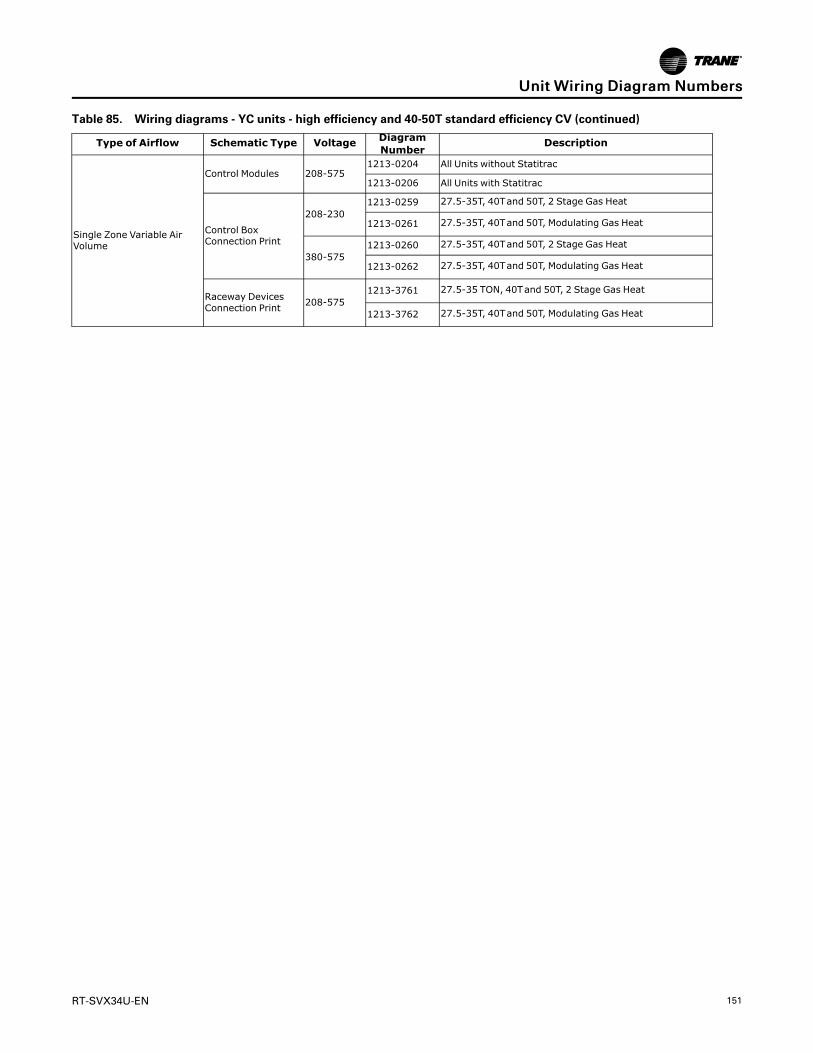
RT-SVX34U-EN 151
Table 85. Wiring diagrams - YC units - high efficiency and 40-50T standard efficiency CV (continued)
Type of Airflow Schematic Type Voltage DiagramNumber
Description
Single Zone Variable AirVolume
Control Modules 208-5751213-0204 All Units without Statitrac
1213-0206 All Units with Statitrac
Control BoxConnection Print
208-2301213-0259 27.5-35T, 40Tand 50T, 2 Stage Gas Heat
1213-0261 27.5-35T, 40Tand 50T, Modulating Gas Heat
380-5751213-0260 27.5-35T, 40Tand 50T, 2 Stage Gas Heat
1213-0262 27.5-35T, 40Tand 50T, Modulating Gas Heat
Raceway DevicesConnection Print 208-575
1213-3761 27.5-35 TON, 40Tand 50T, 2 Stage Gas Heat
1213-3762 27.5-35T, 40Tand 50T, Modulating Gas Heat
UUnniitt WWiirriinngg DDiiaaggrraamm NNuummbbeerrss

152 RT-SVX34U-EN
Warranty and Liability ClauseCOMMERCIAL EQUIPMENT - 20TONS AND LARGER ANDRELATED ACCESSORIESPRODUCTS COVERED - This warranty* is extended byTrane Inc. and applies only to commercial equipmentrated 20 Tons and larger and related accessories.
The Company warrants for a period of 12 months frominitial startup or 18 months from date of shipment,whichever is less, that the Company products coveredby this order (1) are free from defects in material andworkmanship and (2) have the capacities and ratingsset forth in the Company’s catalogs and bulletins,provided that no warranty is made against corrosion,erosion or deterioration. The Company’s obligationsand liabilities under this warranty are limited tofurnishing f.o.b. factory or warehouse at Companydesignated shipping point, freight allowed to Buyer’scity (or port of export for shipment outside theconterminous United States) replacement equipment(or at the option of the Company parts therefore) for allCompany products not conforming to this warrantyand which have been returned to the manufacturer.The Company shall not be obligated to pay for the costof lost refrigerant. No liability whatever shall attach tothe Company until said products have been paid forand then said liability shall be limited to the purchaseprice of the equipment shown to be defective.
The Company makes certain further warrantyprotection available on an optional extra-cost basis.Any further warranty must be in writing, signed by anofficer of the Company.
The warranty and liability set forth herein are in lieu ofall other warranties and liabilities, whether in contractor in negligence, express or implied, in law or in fact,including implied warranties of merchantability andfitness for particular use. In no event shall theCompany be liable for any incidental or consequentialdamages.
THE WARRANTY AND LIABILITY SET FORTH HEREINARE IN LIEU OF ALL OTHER WARRANTIES ANDLIABILITIES, WHETHER IN CONTRACT OR INNEGLIGENCE, EXPRESS OR IMPLIED, IN LAW OR INFACT, INCLUDING IMPLIED WARRANTIES OFMERCHANTABILITY AND FITNESS FOR PARTICULARUSE, IN NO EVENT SHALL WARRANTOR BE LIABLEFOR ANY INCIDENTAL OR CONSEQUENTIALDAMAGES.
Manager - Product Service
Trane
Clarksville, Tn 37040-1008
PW-215-2688
*A 10 year limited warranty is provided on optional FullModulation Gas Heat Exchanger.
*Optional Extended Warranties are available forcompressors and heat exchangers of CombinationGas-Electric Air Conditioning Units.
*A 5 year limited warranty is provided for optional“AMCA 1A Ultra Low Leak” airfoil blade economizerassemblies and the “AMCA 1A Ultra Low Leak”economizer actuator.

RT-SVX34U-EN 153
NNootteess

154 RT-SVX34U-EN
NNootteess

RT-SVX34U-EN 155
NNootteess

Trane - by Trane Technologies (NYSE: TT), a global innovator - creates comfortable, energy efficientindoor environments for commercial and residential applications. For more information, please visittrane.com or tranetechnologies.com.
Trane has a policy of continuous product and product data improvements and reserves the right to change design and specifications withoutnotice. We are committed to using environmentally conscious print practices.
RT-SVX34U-EN 21 Jun 2021
Supersedes RT-SVX34T-EN (February 2021) ©2021 Trane