Embed Size (px)
Citation preview

Installation, Operation and Maintenance ManualPlease read and save these instructions for future reference. Read carefully before attempting to assemble, install, operate or maintain the product described. Protect yourself and others by observing all safety information. Failure to comply with instructions could result in personal injury and/or property damage!
Auto Scrubber Control Panel 1
Document 481510
Auto Scrubber Control Panel
WARNINGElectrical shock hazard. Can cause equipment damage, personal injury or death. Service must only be performed by personal that are knowledgeable in the operation of the equipment being controlled.
DANGER
Always disconnect power before working on or near the product. Lock and tag the disconnect switch or breaker to prevent accidental power up.
CAUTION
When servicing the product, variable frequency drives (if provided) may be hot enough to cause pain or injury. Allow motor to cool before servicing.
CAUTIONIt is the responsibility of the installer to make sure both electrical and gas appliances shut down in the event of a fire or in the event of a power loss to the building when this sequence is required by the authority having jurisdiction.
General Safety InformationOnly qualified personnel should install this product. Personnel should have a clear understanding of these instructions and should be aware of general safety precautions. Improper installation can result in electric shock, possible injury due to coming in contact with moving parts, as well as other potential hazards. If more information is needed, contact a licensed professional engineer before moving forward.
1. Follow all local electrical, plumbing and safety codes, as well as the National Electrical Code (NEC) and the latest edition of the National Fire Protection Agency Standard for Ventilation Control and Fire Protection of Commercial Cooking Operations (NFPA 96). Follow the Canadian Electrical Code (CEC) and ULC-S650 if installing this product in Canada.
2. Do not allow the electrical components of this unit to come in contact with oil, grease, hot surfaces, water, or chemicals.
3. Verify the site can supply the necessary power for each fan and for the control panel.
KVS v2.00

Auto Scrubber Control Panel2
Table of ContentsReceiving and Handling . . . . . . . . . . . . . . . . . . . . . . . . 2Model Identification . . . . . . . . . . . . . . . . . . . . . . . . . . . . 3System Components . . . . . . . . . . . . . . . . . . . . . . . . . . . 3Installation Control Box Mounting . . . . . . . . . . . . . . . . . . . . . . . . 4 Temperature Sensor Mounting . . . . . . . . . . . . . . . . . 4Pneumatic Static Pressure Kit . . . . . . . . . . . . . . . . . . . 5Keypad Mounting, Diagram and Dimensions . . . . . . . . 5Touch Screen Mounting, Diagram and Dimensions . . . 6Plumbing Connections Typical Plumbing Connection Layout . . . . . . . . . . . . 7 Detergent Tank Installation . . . . . . . . . . . . . . . . . . . . 7 Detergent Requirements . . . . . . . . . . . . . . . . . . . . . . 7 Preventative Maintenance (Detergent Pump) . . . . . . 7Electrical Connections Power for Auto Scrubber Control Panel (ASCP) . . . . 8 Power for Lights . . . . . . . . . . . . . . . . . . . . . . . . . . . . 8 Variable Frequency Drives (VFD) . . . . . . . . . . . . . . . . 8 Vari-Green® Fan Wiring . . . . . . . . . . . . . . . . . . . . . . 9 VFD Provided by Others, Control Wiring . . . . . . . . . 9 Make-Up Air VFD in ASCP Wiring . . . . . . . . . . . . . . 9 Make-Up Air VFD in Make-Up Air Wiring . . . . . . . . . 9 Auto Tempering . . . . . . . . . . . . . . . . . . . . . . . . . . . . 10 Fire System Microswitch . . . . . . . . . . . . . . . . . . . . . 10 Hood Solenoids and Temperature Sensors . . . 10-11 Keypad . . . . . . . . . . . . . . . . . . . . . . . . . . . . . . . . . . 11 Touch Screen . . . . . . . . . . . . . . . . . . . . . . . . . . . . . . 11 Remote Enable . . . . . . . . . . . . . . . . . . . . . . . . . . . . 11 Shunt Trip . . . . . . . . . . . . . . . . . . . . . . . . . . . . . . . . 11 Electric Gas Valve with Gas Reset . . . . . . . . . . . . . 11 Spare Fire Relay Contacts . . . . . . . . . . . . . . . . . . . 11 Grease Trapper Pollution Control Unit (PCU) Filter Status . . . . . . . . . . . . . . . . . . . . . . . . . . . . . 12 High Temperature Alarm Contacts . . . . . . . . . . . . . 12 Airflow Proving Switch(es) . . . . . . . . . . . . . . . . . . . . 12 System Wash Contacts . . . . . . . . . . . . . . . . . . . . . . 13 System Fan Contacts . . . . . . . . . . . . . . . . . . . . . . . 13 Exhaust/Supply Fan Contacts . . . . . . . . . . . . . . . . . 13 Fan Input . . . . . . . . . . . . . . . . . . . . . . . . . . . . . . . . . 13
Wash Input . . . . . . . . . . . . . . . . . . . . . . . . . . . . . . . 14 Duct Sump Solenoids . . . . . . . . . . . . . . . . . . . . . . . 14 Power for Starters and Fans . . . . . . . . . . . . . . . . . . 14ASCP Connection Checklist . . . . . . . . . . . . . . . . . 15-16 Typical Electrical Connection Layout . . . . . . . . . . . 17Sequence of Operation - ASCP-W . . . . . . . . . . . . . . . 18Sequence of Operation - ASCP-B and ASCP-K . . . . 19Sequence of Operation - ASCP-V . . . . . . . . . . . . . . . 20Sequence of Operation - Fire and Alarm Operation . . 21System Optimization - ASCP-V Panel Only . . . . . . . . 21Controller Setup and Tutorial . . . . . . . . . . . . . . . . . . . 22Hood/System Status . . . . . . . . . . . . . . . . . . . . . . . . . . 23Example of Alarms . . . . . . . . . . . . . . . . . . . . . . . . . . . 24 Menus A. Fan Status . . . . . . . . . . . . . . . . . . . . . . . . 25 B. Clock . . . . . . . . . . . . . . . . . . . . . . . . . . . . 26 C. Input/Output . . . . . . . . . . . . . . . . . . . . . . . 26 D. Service . . . . . . . . . . . . . . . . . . . . . . . . 27-36 E. Manufacturer . . . . . . . . . . . . . . . . . . . 36-39Initial System Start-Up . . . . . . . . . . . . . . . . . . . . . . . . 40Wash Operation & Wash Sequence of Operation . 41-43Keypad Navigation . . . . . . . . . . . . . . . . . . . . . . . . . . . 44Touch Screen Navigation . . . . . . . . . . . . . . . . . . . 45-46General Information . . . . . . . . . . . . . . . . . . . . . . . . . . . 46 Settings . . . . . . . . . . . . . . . . . . . . . . . . . . . . . . . 46-50 Configuration . . . . . . . . . . . . . . . . . . . . . . . . . . . 50-51 Information . . . . . . . . . . . . . . . . . . . . . . . . . . . . . . . 52Troubleshooting . . . . . . . . . . . . . . . . . . . . . . . . . . 53-54Variable Frequency Drive (VFD) Information . . . . . . . . 55 Model V1000 Changing Parameters and Monitor Motor Frequency and Motor Current . . . . . . . . . . . 56 Model A1000 Changing Parameters and Monitor Motor Frequency and Motor Current . . . . . . . . . . . 56Building Management System (BMS) Points List ASCP v2.00 Modbus/BACnet® . . . . . . . . . . . . 57-59 ASCP v2.00 LonWorks® . . . . . . . . . . . . . . . . . . 60-61Maintenance Log . . . . . . . . . . . . . . . . . . . . . . . . . . 62-63Our Commitment . . . . . . . . . . . . . . . . . . . . . . Backcover
Receiving and HandlingReceivingUpon receiving the product, check to make sure all items are accounted for by referencing the bill of lading to ensure all items were received. Notify the carrier if any damage is noticed. The carrier will make notification on the delivery receipt acknowledging any damage to the product. All damage should be noted on all of the copies of the bill of lading which is countersigned by the delivering carrier. If damaged upon arrival, file a claim with the carrier. Any physical damage to the unit after acceptance is not the responsibility of the manufacturer.
UnpackingVerify that all required parts and the correct quantity of each item have been received. If any items are missing, report shortages to your local representative to arrange for obtaining missing parts.
StorageIf a ASCP must be stored prior to installation, it must be protected from dirt and moisture. Indoor storage is highly recommended.
HandlingMake sure the equipment does not suffer any heavy vibration or knocks.
NOTEImproper storage which results in damage to the unit will void the warranty.

Auto Scrubber Control Panel 3
Model IdentificationASCP-W Auto Scrubber Wash Only – No Fan Controls
This configuration does not include any fan controls, and will only be responsible for washing the hoods and/or duct sumps. All fan controls and starters/VFDs are to be provided in the field.
ASCP-BAuto Scrubber Basic On/Off Fan Controls,
Fan Starters/VFDs by Others
This configuration includes wash control of hoods and/or duct sumps, and also is provided with fan control in the form of simple dry contacts that can be used to tie into fan starters/VFDs. All fan starters/VFDs are to be provided in the field. Relay contacts to engage starters/VFDs are rated up to 8 amps and 250 VAC.
ASCP-KAuto Scrubber Kitchen Fan Control Center (XFCC)
This configuration includes wash control of hoods and/or duct sumps, and also provides fan controls with fan starters (this panel is integrated with a constant volume, fan control center).
ASCP-VAuto Scrubber Vari-Flow (Variable Volume)
This configuration includes wash control of hoods and/or duct sumps, and also provides fan controls with VFDs (this panel is integrated with the “Vari-Flow” variable volume functionality).
System ComponentsAuto Scrubber Control Panel (ASCP)
The control cabinet contains the water and electrical components, including the Programmable Logic Controller (PLC), that controls wash sequencing and operations. The control cabinet also includes the detergent reservoir, detergent pump, and other water piping.
Backflow Preventer
A backflow preventer will be shipped loose with the ASCP and will need to be installed in-line with the hot water supply to the ASCP to prevent detergent from back-feeding into the building water supply. Plumbing instructions begin on page 6.
User Interface
The user interface will be either a keypad with LCD screen or touch screen. It can be mounted on the Auto Scrubber control cabinet, hood or shipped loose for remote mounting. It will provide a WASH button (WASH ON/OFF with touch screen), and a means of turning on/off hood fans and lights, if applicable. It also includes system alarm notifications to alert of any faults on the system, such as low detergent alarm.
NOTEControl panel will be shipped with (and will be controlling) either an Auto Scrubber hood, duct sump, or a combination of both. For more detailed information on the Auto Scrubber hood or duct sump, please refer to the Accurex website at www.accurex.com
MENUNAV
SYSTEM FAULT
Keypad Touch Screen

Auto Scrubber Control Panel4
NOTETemperature sensor(s) may be factory installed. If so, continue to the next section.
Temperature Sensor(s) Mounting - if equipped
1. Locate flat space at the top interior of the hood in front of the filters, towards the front of the hood.
3. Center the octagon extension over the hole on the hood surface.
2. Find a spot for the sensor in the flat space that will not interfere with the fire suppression nozzles and that is not within 12 inches (304.8 mm) of any light fixtures. Cut a 3/4 to 7/8-inch (19.0 to 22.2 mm) diameter hole in the flat spot of the capture tank.
Control Box Mounting1. Locate an area with enough space to mount the
control box and fasten to the wall.
.75 to .875 inchdiameter hole
HoodSurface
4. Insert the compression seal into the hole from the inside of the hood making sure the gasket is placed on the fitting before inserting it into the hole. Place the octagon box and J-box plate provided over the fitting on the top of the hood, keeping the fitting centered in the box. Install the lock washer and 1-1/2 inch (38.1 mm) nut on the threaded portion of the compression seal and tighten securely.
1/4 inch Compression Seal
Gasket
J-Box Plate
TemperatureSensor
Lock WasherNut
Octagon Cover
5. Insert the temperature sensor into compression seal and tighten to 35 ft-lbs (47.5 Nm).
6. Place octagon cover onto J-box plate and fasten it.
NOTEControl box may be factory mounted. If so, continue to the next section.
NOTEIf the ASCP is configured for variable volume (ASCP-V) and the panel is equipped with static pressure control, it will be located in the ASCP. Therefore, this control box should be mounted in the space to be controlled. Refer to the Pneumatic Static Pressure Kit section for installation instructions of the pressure sensor kit on page 5.
OctagonExtension
Exhaust Area
Supply Area (optional)
Sensor Install Cut Out Area
Top View of Exhaust Hood
Installation

Auto Scrubber Control Panel 5
Pneumatic Static Pressure Kit - if equipped
1. Locate the Kele® static pressure sensor outside of the building in a secure location free from as many obstructions as possible.
2. Refer to the instruction manual with the static pressure sensor for installation and operation details.
3. Once the static pressure probe is mounted, run vinyl tubing from the probe back to the control panel and coil the excess tubing. Do not kink or trim the tubing.
4. If the control panel is located in the space to be controlled, go to the next section. If the control panel is mounted remotely from the space to be controlled, continue to step 5.
5. Run 1/4 inch (6.4 mm) virgin poly tubing (by others) from the sensor in the control panel to a secure location in the space to be controlled.
NOTEThe keypad may be factory mounted. If so, continue to the Electrical Connections section.
1. For systems with remote controls or keypad, a 35, 75, or 150 foot RJ25 cable is supplied to connect the keypad to the controls. The cable is plenum rated and does not need to be run through conduit unless required by local codes. If the keypad is to be mounted further away than the cable that is received, additional cable will be needed. Additional cable is available at the lengths mentioned above.
Keypad Mounting - if equipped
Keypad Mounting Diagram
Keypad Dimensions
5.25 inches(133.4 mm)
7.625 inches(193.7 mm)
7.0 inches(177.8 mm)
2.25 inches(57.2 mm)
4.625 inches(117.5 mm)
Ø0.875 inches(22.2 mm)
Top View
Front View
Side View

Auto Scrubber Control Panel6
NOTEThe touch screen may be factory mounted. If so, continue to the Electrical Connections section.
Touch Screen Mounting - if equipped
Touch Screen Mounting Diagram
Touch Screen Dimensions
1. For systems with remote controls or touch screen, two 35, 75, or 150 foot sets of cables are supplied to connect the touch screen to the controls. The cables are plenum rated and do not need to be run through conduit unless required by local codes. If the keypad is to be mounted further away than the cable that is received, additional cable will be needed. Additional cables are available at the lengths mentioned above.
Ø0.875 inches(22.2 mm)
9.15 inches(232.4 mm)
8.5 inches(215.9 mm)
2.5 inches(63.5 mm)
7.0 inches(177.8 mm)
7.60 inches(193.0 mm)
Top View
Front View
Side View
Plumbing Connections
1. Install the factory provided backflow preventer (shipped loose) and drain connection per local codes.
2. Bring 1-inch (25.4 mm) hot water supply line to the backflow preventer.
3. Plumb 1-inch (25.4 mm) line from outlet of backflow preventer to the hot water inlet in the control cabinet.
4. If the cabinet is remote mounted, connect the hot water outlet on the controls cabinet to the hot water inlet on the top of the hood.
If the control panel is washing duct sumps, connect the hot water outlet on the controls cabinet to all duct sump solenoids.
5. If system is configured for cold water mist, bring 0.75-inch (19.05 mm) water piping to the cold water mist inlet in the control cabinet.
6. If the cabinet is remote mounted and the system is configured for cold water mist, connect the cold water mist outlet on the controls cabinet to each hood with a cold water mist solenoid valve
7. Plumb 2-inch (50.8 mm) drain on each hood to grease trap (floor).
NOTE• Hot water temperature should be 140°F (60°C).• While the hood is washing, water pressure in the
control panel should be between 40 and 70 PSI (275.8 and 482.6 kPA).
• Cold mist water pressure should be between 20 and 40 PSI (137.9 and 275.8 kPA).
FROM 1 INCHHOT WATER SUPPLY
TO ASCP 1 INCHHOT WATER INLET
TOP VIEW OF AUTO SCRUBBER CONTROL PANEL (ASCP)
FRONT VIEW OF AUTO SCRUBBER CONTROL PANEL (ASCP)
1
1
1. Electrical Control Cabinet 5. Hot Water Inlet Connection2. Detergent Pump 6. Cold Water Outlet Connection to Hood3. Detergent Tank 7. Cold Water Inlet Connection4. Hot Water Outlet Connection to Hood 8. Inlet Valve
3
4
5
6
7
8
22
Backflow Preventer

Auto Scrubber Control Panel 7
Plumbing Connections - continued
Detergent RequirementsDetergent model X-701 manufactured by ZEP, Inc., is recommended by Accurex for use in the wash system. This product is biodegradable, non-caustic, and safe for kitchen staff to use. If X-701 detergent is not used, the cleanliness of the exhaust plenum and filters cannot be guaranteed.
Preventative MaintenanceThe following practices will prolong the life of the detergent pump:• Keep detergent tank filled.• Avoid spilling detergent on the exterior of the pump.• Clean the detergent tank at least every six months.• Clean the detergent line strainer at least every six
months.• Check tightness of all fittings periodically.The detergent pump motor has sealed bearings which do not require lubrication.
NOTE• X-701 is manufactured by ZEP, Inc., Atlanta, GA,
USA. For details and ordering information, call 1-877-428-9937.
• If washed once a day, the 2.5 gallon detergent tank will last approximately 24 to 30 days depending on filter type.
Detergent Tank InstallationThe detergent tank is located in the plumbing section of the ASCP. The tank provided can hold up to 2.5 gallons (9.5 liters) of detergent. It will need to be checked periodically depending on detergent use and filled with the recommended chemical detergent. The tank is also equipped with a float that will trigger an alarm to warn the user when detergent is low.
Steps for removal and installation of the detergent tank are as follows:
Removal:
1. Disconnect the two float switch wires at the quick connect electrical fittings.
2. Remove the 1/4-inch (6.35 mm) detergent line that enters the tank thru the screw on cap.
3. Lift out the detergent tank from the utility cabinet.4. Unscrew the 63 mm cap from the tank; this will
remove the float assembly.5. Fill the tank with the approved detergent.Install:
1. Install the 63 mm cap and float assembly into the detergent tank.
2. Lift the detergent tank back into the utility cabinet.3. Install the 1/4-inch (6.35 mm) detergent line thru the
hole in the 63 mm cap.4. Connect the two float switch wires at the quick
connect electrical fittings.
Typical Plumbing Connection Layout
First Auto Scrubber Hood
HOT WATER CONNECTIONS:
A 1-inch hot water supply from building to Backflow Preventer
B 1-inch hot water piping from Backflow Preventer to control cabinet
C 1-inch hot water piping from control cabinet to hood(s) and/or sump(s)
COLD WATER CONNECTIONS, optional with continuous cold water mist
D 3/4-inch cold water supply from building to control cabinet
E 3/4 inch cold water piping from control cabinet to hood(s)
DRAIN CONNECTIONS FROM AUTO SCRUBBER HOOD(S):
F 2-inch male NPT connection to building drain with grease trap (one per hood section)
G 1.5-inch female NPT connection to building drain with grease trap (one per sump)
Plumbing Key
Auto Scrubber Control Panel
(ASCP)
BackflowPreventer
Provided by Accurex; field installed. Drain requiredfor backflow preventer.
Plumbing connections made here
Hot Water PipingCold Water Piping
BuildingWaterSupply
Each additionalAuto Scrubber Hood
(if applicable)
Duct Sump (if applicable)
FF
FF
GG
CCBBAA
DD
EE

Auto Scrubber Control Panel8
Variable Frequency Drives (VFD) - if equipped
NOTEIf electrically commutated motors are being used, VFDs will not be needed.
1. Bring power to the input of each VFD from a dedicated power source using conduit to the NEMA-1 enclosure on the bottom of the drive. Each power source shall be of the same voltage as the respective fan and of a high enough amp rating to handle the full load amp draw of the respective fan.
NOTEThe VFD motor overload parameter (E2-01) needs to be set to match the motor nameplate FLA. Refer to the Quick Start Guide from Yaskawa (pages 83-89), or the Variable Frequency Drive information found on pages 32-33 for setting these parameters on the drive.
NOTEBe sure to use appropriately sized wire for the full load amp draw.
2. To avoid interference between the conductors, separate conduit from the VFD output to the input power of the fan must be used for each fan.
Each variable frequency drive must have the LINE and LOAD wiring in separate conduit.
L3
VFD
L2L1 T3
LOADT2T1
E1MARK NAME
VOLT/PHASE HPADDRESS: X
IGR+ R- S+ S-
SEE MODBUS COMMUNICATION DETAIL
G
LINEBUILDING
BREAKER PANEL
E1
EXHAUST FAN
CONTROL INPUT: 115 VAC, 15 AMPS FROM BREAKER
H N
G
NOTEAll wiring of electrical equipment must be done to meet NEC and local codes.
NOTEIt is recommended that shielded wire be used for all low voltage connections (24V or less) to prevent signal interference with other high voltage circuits.
NOTEAll 115 VAC field wiring (or higher) must be high temperature rated and must be routed through hard or flex conduit. All low voltage field wiring should be plenum rated if not routed through conduit. Field wiring should not come in contact with the surface of the hood. To reduce the likelihood of electromagnetic disturbance, avoid routing high and low voltage cables in the same conduit.
Electrical Connections
Power for Lights - if equipped
• 115 VAC, power for hood lights, one per light circuit (Terminals H1, N1 | H2, N2 | H3, N3 | H4, N4)
• 115 VAC, power to lights, one per light circuit (Terminals B1, W1 | B2, W2 | B3, W3 | B4, W4)
Power for ASCP
• 115 VAC, power for controls (Terminals H and N)
R__
HOOD LIGHT RELAY 1
1411
HOOD LIGHT(S)
LIGHT CIRCUIT 1: 115 VAC, 15 AMPS FROM BREAKER
H1 W1B1
EACH CANOPY LIGHTING CIRCUIT MUST NOT EXCEED 15A TOTAL CURRENT
N1WH 14GABK 14GA BK 14GA
G
R__
HOOD LIGHTRELAY 2
1411BK 14GA
HOOD LIGHT(S)
H2 B2 N2W2
LIGHT CIRCUIT 2: 115 VAC, 15 AMPS FROM BREAKER
WH 14GABK 14GA
R__
HOOD LIGHTRELAY 3
1411
HOOD LIGHT(S)
H3 B3 N3W3
LIGHT CIRCUIT 3: 115 VAC, 15 AMPS FROM BREAKER
WH 14GABK 14GA BK 14GA
R__
HOOD LIGHTRELAY 4
1411
HOOD LIGHT(S)
H4 B4 N4W4
LIGHT CIRCUIT 4: 115 VAC, 15 AMPS FROM BREAKER
WH 14GABK 14GA BK 14GA

Auto Scrubber Control Panel 9
NOTEIf the VFD by others is a supply fan, control terminals will begin with a ‘S’ instead of an ‘E’.
NOTESome Vari-Green motors do not require the 24 VAC wire.
Vari-Green® Fan Wiring - if equipped
• 24 VAC from ASCP to Vari-Green motor control wire, black (Terminal E__-24)
• 0-10 VDC Speed Reference from ASCP to Vari-Green motor control wire, red (Terminal E__S+)
• Common from ASCP to Vari-Green motor control wire, white (Terminal E__S-)
This is an example of Exhaust Fan 1 provided with Vari-Green motor.
G
EXHAUST FANVARI-GREEN MOTOR
N
H
E1MARK NAME
VOLT/PHASE HPVARI-GREEN
24 VAC RUN (BLACK)
SPEED REF. + (RED)
SPEED REF. - (WHITE)
NOTE: POWER FOR THE VARI-GREEN FAN GOES DIRECTLY TO FAN
E1-24
E1-S+
E1-S-
24H
24C
BL
ORYW
BUILDINGBREAKER PANEL LINE
WIRE HARNESS
FROM U1 CONTROLLER Y_
N
G
NOTEThis wiring is only applicable with ASCP-V packages.
VFD Provided by Others, Control Wiring - if equipped
• Fault command from ASCP to VFD provided by others (Terminal E__-FA, E__-FB)
• Run command from ASCP to VFD provided by others (Terminal E__-RA, E__-RB)
• Speed reference from ASCP to VFD provided by others (Terminal E__S+, E__S-)
• Line power to VFD • Load power from VFD to fan
This is an example of Exhaust Fan 1 provided with a VFD by others.
E1MARK NAME
VOLT/PHASE HP
E1
EXHAUST FAN
BUILDINGBREAKER PANEL
L1
L2
L3
LINEVFD - BY OTHERS
E1-FA
E1-FB
E1-RA
E1-RB
E1-S+
E1-S-
R_1411
EF-FA
EF-FB
24C
PR
PR
YWOR
RD
RD
COMMON
NORMALLY OPEN
RUN COMMAND
RUN COMMAND
SPEED REFERENCE +
SPEED REFERENCE -
FAULT CONTACT
T3
LOADT2T1
G
FROM U1 CONTROLLER Y_
Make-Up Air VFD in Make-Up Air Wiring - if equipped
• 24 VAC run command from ASCP to make-up air unit (Terminals S__-42, S__-43)
• Tempering status from ASCP to make-up air unit (Terminals S__-44, S__-45)
• 0-10 VDC speed reference from ASCP to make-up air unit (Terminals S__-46, S__-47)
Power for make-up air goes directly to make-up air unit.
This is an example of Supply Fan 1 being a make-up air with VFD in the make-up air unit.
S1MARK NAME
VOLT/PHASE HP
BL
YW
(43) COM
(42) RUN
(45) TEMPERING STATUS
(44) TEMPERING STATUS24C
SE
PAR
ATE
CO
NTR
OL
PO
WE
R
TO U
NIT
RE
QU
IRE
D
24 VAC
YW
S1-42
S1-43
S1-44
S1-45
S1-46
S1-47
(46) SPEED REFERENCE +
(47) SPEED REFERENCE -(0-10 VDC)
24C OR
MUA - VFD IN UNIT
NOTE: POWER FOR MUA GOES DIRECTLY FROM BREAKER PANEL TO MUA.
BUILDINGBREAKER PANEL
42
43
44
45
46
47
FROM U1 CONTROLLER NO_
FROM U1 CONTROLLER Y_
Make-Up Air VFD in ASCP Wiring - if equipped
• 24 VAC run command from ASCP to make-up air unit (Terminals S__-42, S__-43)
• Tempering status from ASCP to make-up air unit (Terminals S__-44, S__-45)
• Line power to VFD input, bottom left of VFD (Terminals L1, L2, L3)
• Load power from VFD output, bottom right of VFD to make-up air disconnect (Terminals T1, T2, T3)
Make-up air unit requires separate 115 VAC or 3-phase control power circuit. See the MUA wiring diagram for details.
This is an example of Supply Fan 1 being a make-up air with VFD in the ASCP.
S1MARK NAME
VOLT/PHASE HP ADDRESS: X
(43) COM
(42) RUN
(45) TEMPERING STATUS
(44) TEMPERING STATUS24C
SE
PAR
ATE
CO
NTR
OL
PO
WE
R
TO U
NIT
RE
QU
IRE
D
24 VAC
BL
YW
L3L2L1 T3
LOADT2T1
LINE
S2-42
S2-43
S2-44
S2-45
42
43
44
45
MUA UNITBUILDING
BREAKER PANEL
VFDIGR+ R- S+ S-
SEE MODBUS COMMUNICATION DETAIL
FROM U1 CONTROLLER NO_

Auto Scrubber Control Panel10
Fire System Microswitch
• Fire system microswitch common to ASCP (Terminal C1)
• Fire system microswitch normally closed contact to ASCP (Terminal NC1)
C1C
NC1NC
MS1
Auto Tempering - if equipped
• Auto Heat/Cool enable (Terminals S1-R, S1-W1, S1-Y1)
This is an example of Supply Fan 1 with auto tempering (VFD in make-up air unit).
S1MARK NAME
VOLT/PHASE HP
BL
YW
(43) COM
(42) RUN
(45) TEMPERING STATUS
(44) TEMPERING STATUS24C
SE
PAR
ATE
CO
NTR
OL
PO
WE
R
TO U
NIT
RE
QU
IRE
D
24 VAC
YW
S1-42
S1-43
S1-44
S1-45
S1-46
S1-47
(46) SPEED REFERENCE +
(47) SPEED REFERENCE -(0-10 VDC)
24C OR
MUA - VFD IN UNIT
NOTE: POWER FOR MUA GOES DIRECTLY FROM BREAKER PANEL TO MUA.
BUILDINGBREAKER PANEL
42
43
44
45
46
47
FROM U1 CONTROLLER NO_
FROM U1 CONTROLLER Y_
(Y1) COOL
(R) CONTROL COMMON
(W1) HEAT
S1-Y1
S1-R
S1-W1R_
1114
PR
PR
PR Y1
W1
R
Hood Solenoids and Temperature Sensor(s) - if equipped
Wash Hood Solenoids
• Wire between control panel terminal WO-_A and hood j-box terminal WO-_A
• Wire between control panel terminal WO-_B and hood j-box terminal WO-_B
• Wire between control panel terminal 24C and hood j-box terminal 24C
• Wire between control panel terminal GND and hood j-box terminal GND
Wash Hood Temp Sensor 1 – if equipped
• Wire between control panel terminal T_-A and hood j-box terminal T_-A
• Wire between control panel terminal T_-B and hood j-box terminal T_-B
Wash Hood Temp Sensor 2 – if equipped
• Wire between control panel terminal T_-A and hood j-box terminal T_-A
• Wire between control panel terminal T_-B and hood j-box terminal T_-B
J-BOX HOOD #_
MAINCONTROL
WASH SOL _SV_
WASH SOL _SV_
24C
WO-_B
GND
T_-A
T_-A
T_-B
T_-B
T_-A
T_-A
T_-B
T_-B
WO-_A
24C
GND
WO-_B
WO-_A
T_
T_
Each Auto Scrubber hood will include an 8x8x4 enclosure factory wired to the hood solenoids and sensors. If the Auto Scrubber Control Panel (ASCP) is not mounted on the hood, the field will need to wire from the 8x8x4 enclosure back to the ASCP. The hood sensors and solenoids are low voltage, therefore, 18 gauge stranded wire is recommended. The two wires of each hood sensor are not polarity sensitive.
The wiring diagram provided with the ASCP will display a table showing which sensors/solenoids connect to each hood. If more than one hood is being controlled, be sure that the appropriate sensor/solenoid is wired to the appropriate terminals as depicted on this diagram.

Auto Scrubber Control Panel 11
Hood Solenoids and Temperature Sensor(s) - if equipped (continued)
Keypad - if equipped
• Connect provided cable from back of keypad to CAREL® PCO5+ controller (Terminal J10)
PCO5+ J10 KEYPAD
CONNECT FACTORY PROVIDED RJ25 CABLE TO J10 ON PCO5+ AND BACK OF KEYPAD
35 Foot Cable Provided75 or 150 Foot Cable is Optional
Touch Screen - if equipped
Power Wiring • Connect provided 2-wire cable from ASCP
(Terminals TS24, TSC) to touch screen (Terminals G, GO)
Control Wiring • Connect provided 3-wire cable from ASCP
(Terminals -, +, GND) to touch screen (Terminals -, +, GND)
TS24
TSC
Power Wiring
-
+
GND
Control Wiring
-
+
GND
GO
G
J25 (BMS2)
TOUCH SCREEN
TOUCH SCREEN
CAUTIONEach sensor is a low voltage, resistive temperature detector. They are not a high voltage switch/thermostat. Do not connect temperature sensors in series/parallel with high voltage. This can result in damage to the temperature sensor and will require replacement.
NOTEEach temperature sensor is rated up to 250°F (121.1°C), and therefore should not be exposed to direct flame. Exposing sensors to direct flame may render the sensor inoperable and replacements will not be covered under warranty.
Remote Enable - if equipped
• Connect remote enable common and normally open from BMS to ASCP (Terminals RE-1A, RE-1B)
A closed contact will turn on all fans. An open contact will turn off all fans.
RE-1A RE-1B
NOTETemperature interlock will override the remote enable input.
Spare Fire Relay Contacts - if equipped• Power to common (Terminal C3)• Power out, normally open, closed in fire
(Terminal NO3)• Power out, normally closed, open in fire
(Terminal NC3)
• Power to common (Terminal C4)• Power out, normally open, closed in fire
(Terminal NO4)• Power out, normally closed, open in fire
(Terminal NC4)
OPEN WITH POWER AT H & N & FIRE SYSTEM ARMEDCLOSED ON FIRE OR NO POWER
CLOSED WITH POWER AT H & N & FIRE SYSTEM ARMEDOPEN ON FIRE OR NO POWER
A
B
C3
NO3
NC3
C4
NO4
NC4
RF2
12
14
11 22
24
21A
B
RF2A
B
Shunt Trip - if equipped• 115 VAC from ASCP to shunt trip breaker coil
(provided by others) (Terminals STH, STN)Voltage across STH, STN when in fire will be 115 VACVoltage across STH, STN when not in fire will be 0 VAC
STH STNSTB
NOTEShunt trip contacts will lose voltage during momentary losses in power to the ASCP, tripping the connected shunt trip breaker. If installed in areas with frequent losses in power, it is recommended that all shunt trip breakers be wired through a normally open (N.O.) contact of an additional fire system microswitch instead.
Electric Gas Valve with Gas Reset - if equipped • 115 VAC from ASCP to gas solenoid
(Terminals SVH, SVN)Voltage across SVH, SVN when in fire will be 0 VACVoltage across SVH, SVN when not in fire and turn on will be 115 VAC
SVH SVNSV2
SV1

Auto Scrubber Control Panel12
High Temperature Alarm Contacts - if equipped• Power to common (Terminal HT-C)• Power out, normally closed, open in high
temperature alarm (Terminal HT-NC)• Power out, normally open, closed in high
temperature alarm (Terminal HT-NO)
CLOSED WITH POWER AT H & N & HIGH TEMPALARM INACTIVE, CLOSED WITH NO POWER
CLOSED WITH POWER AT H & N & FIRE SYSTEM ARMED, OPEN ON FIRE OR NO POWER
A
B
HT-C
HT-NC
HT-NO
R_
24
22
21A
B
AP-1A AP-1BAIR PROVING SUPPLY FAN 1
AP-2A AP-2BAIR PROVING SUPPLY FAN 2
AP-3A AP-3BAIR PROVING SUPPLY FAN 3
AP-4A AP-4BAIR PROVING SUPPLY FAN 4
Airflow Proving Switch(es) (provided by others) - if equipped • Common and normally open from supply fan 1 air
proving switch to ASCP (Terminals AP-1A, AP-1B) • Common and normally open from supply fan 2 air
proving switch to ASCP (Terminals AP-2A, AP-2B) • Common and normally open from supply fan 3 air
proving switch to ASCP (Terminals AP-3A, AP-3B) • Common and normally open from supply fan 4 air
proving switch to ASCP (Terminals AP-4A, AP-4B)
NOTEAir proving switch(es) are not provided with the ASCP
Grease Trapper Pollution Control Unit (PCU) Filter Status - if equipped• PCU filter 24 VAC hot from terminal FH in enclosure
on the access side of the unit to ASCP (Terminal FH)
• PCU filter 1 module status from terminal F1 in enclosure on access side of the unit to ASCP (Terminal F1)
• PCU filter 2 module status from terminal F2 in enclosure on access side of the unit to ASCP (Terminal F2)
• PCU filter 3 module status from terminal F3 in enclosure on access side of the unit to ASCP (Terminal F3)
FH F1PCU FILTER STATUS MODULE 1
F2PCU FILTER STATUS MODULE 2
F3PCU FILTER STATUS MODULE 3

Auto Scrubber Control Panel 13
OPEN WITH POWER AT H & N & WASH HOODINACTIVE, CLOSED WITH NO POWER
CLOSED WITH POWER AT H & N & WASH HOODACTIVE, OPEN WITH NO POWERA
B
R_
24
22
21A
B
R_
14
12
11A
B
C5
NO5
NC5
C6
NO6
NC6
System Wash Contacts
• Power to common (Terminal C5) • Power out, normally open, closed when wash active
(Terminal NO5) • Power out, normally closed, open when wash active
(Terminal NC5)
• Power to common (Terminal C6) • Power out, normally open, closed when wash active
(Terminal NO6) • Power out, normally closed, open when wash active
(Terminal NC6)
R_
24
22
21A
B
R_
14
12
11
C7
NO7
NC7
C8
NO8
NC8
A
B
OPEN WITH POWER AT H & N & FAN INACTIVE, CLOSED WITH NO POWER
CLOSED WITH POWER AT H & N & FAN ACTIVE, OPEN WITH NO POWERA
B
System Fan Contacts – if equipped
These terminals will only be available with the ASCP-W configuration (Auto Scrubber Control Panel with Wash Only Control). These terminals can be utilized by external panels that are controlling fans to know when fans need to run during the dry sequence of a wash cycle.
• Power to common (Terminal C7) • Power out, normally open, closed when fans should
run (Terminal NO7) • Power out, normally closed, open when fans should
run (Terminal NC7)
• Power to common (Terminal C8) • Power out, normally open, closed when fans should
run (Terminal NO8) • Power out, normally closed, open when fans should
run (Terminal NC8)
R_
24
22
21A
B
R_A
B14
12
11
R_
24
22
21A
B
R_A
B14
12
11
SYSTEM EXHAUST FAN CONTACTS - MELINK, BMS, OTHER
SYSTEM SUPPLY FAN CONTACTS - MELINK, BMS, OTHER
C7
NO7
NC7
C8
NO8
NC8
C11
NO11
NC11
C12
NO12
NC12
OPEN WITH POWER AT H & N & FAN INACTIVE, CLOSED WITH NO POWER
CLOSED WITH POWER AT H & N & FAN ACTIVE, OPEN WITH NO POWERA
B
OPEN WITH POWER AT H & N & FAN INACTIVE, CLOSED WITH NO POWER
CLOSED WITH POWER AT H & N & FAN ACTIVE, OPEN WITH NO POWERA
B
Exhaust/Supply Fan Contacts – if equipped
These terminals will only be available with the ASCP-B configuration (Auto Scrubber Basic On/Off Fan Controls – Fan Starters/VFDs by Others). These terminals can be utilized to engage/disengage externally-provided fan starter(s) or VFD(s).
• Power to common (Terminal C7) • Power out, normally open, closed when exhaust
fan(s) should run (Terminal NO7) • Power out, normally closed, open when exhaust
fan(s) should run (Terminal NC7)
• Power to common (Terminal C8) • Power out, normally open, closed when exhaust
fan(s) should run (Terminal NO8) • Power out, normally closed, open when exhaust
fan(s) should run (Terminal NC8)
• Power to common (Terminal C11) • Power out, normally open, closed when supply fan(s)
should run (Terminal NO11) • Power out, normally closed, open when supply fan(s)
should run (Terminal NC11)
• Power to common (Terminal C12) • Power out, normally open, closed when supply fan(s)
should run (Terminal NO12) • Power out, normally closed, open when supply fan(s)
should run (Terminal NC12)
RE-1A RE-1BFAN INPUT
Fan Input – if equipped
• On the ASCP-W configuration, this input will stop a wash if closed (Terminals RE-1A and RE-1B)
Auto Scrubber Control Panel14
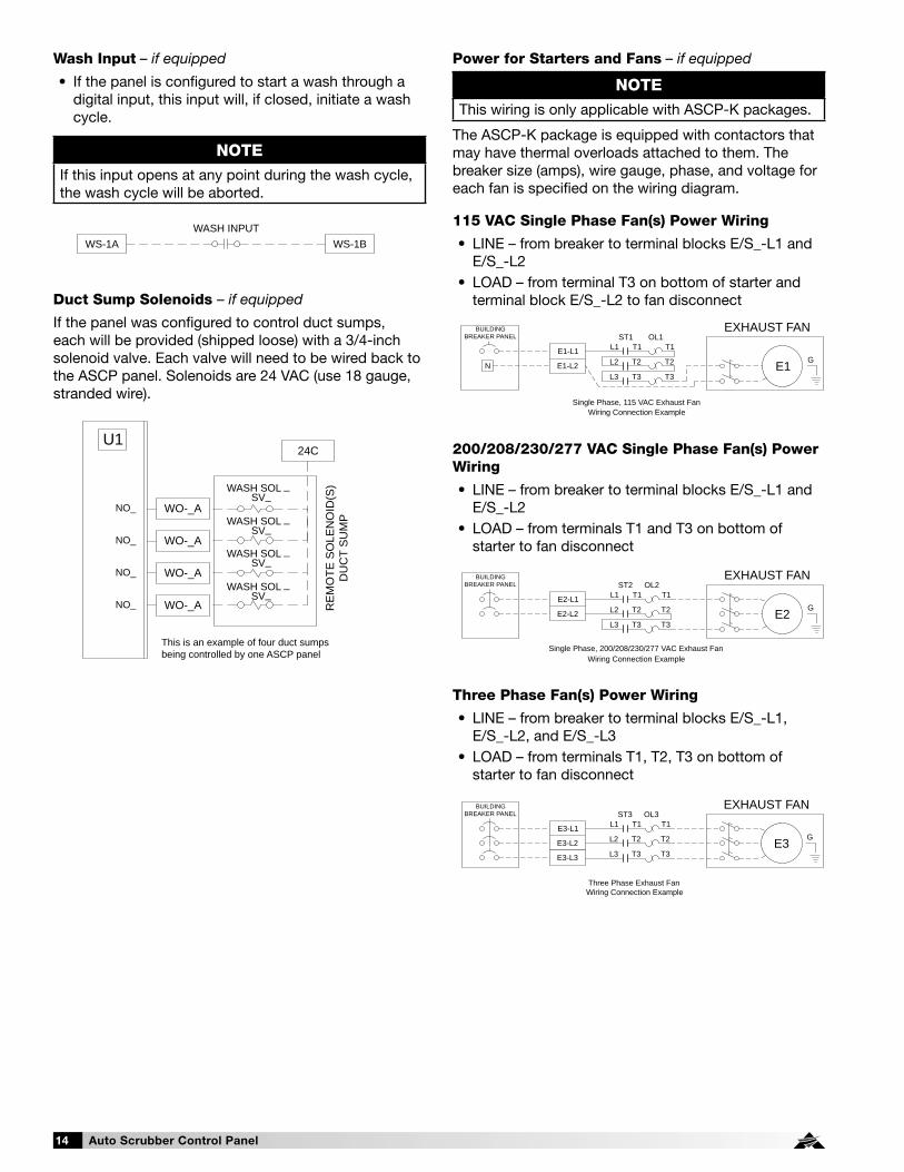
115 VAC Single Phase Fan(s) Power Wiring
• LINE – from breaker to terminal blocks E/S_-L1 and E/S_-L2
• LOAD – from terminal T3 on bottom of starter and terminal block E/S_-L2 to fan disconnect
200/208/230/277 VAC Single Phase Fan(s) Power Wiring
• LINE – from breaker to terminal blocks E/S_-L1 and E/S_-L2
• LOAD – from terminals T1 and T3 on bottom of starter to fan disconnect
Three Phase Fan(s) Power Wiring
• LINE – from breaker to terminal blocks E/S_-L1, E/S_-L2, and E/S_-L3
• LOAD – from terminals T1, T2, T3 on bottom of starter to fan disconnect
Power for Starters and Fans – if equipped
The ASCP-K package is equipped with contactors that may have thermal overloads attached to them. The breaker size (amps), wire gauge, phase, and voltage for each fan is specified on the wiring diagram.
Wash Input – if equipped
• If the panel is configured to start a wash through a digital input, this input will, if closed, initiate a wash cycle.
Duct Sump Solenoids – if equipped
If the panel was configured to control duct sumps, each will be provided (shipped loose) with a 3/4-inch solenoid valve. Each valve will need to be wired back to the ASCP panel. Solenoids are 24 VAC (use 18 gauge, stranded wire).
WASH INPUTWS-1A WS-1B
RE
MO
TE S
OLE
NO
ID(S
)D
UC
T S
UM
P
24C
WO-_ANO_
WASH SOL _ SV_
WASH SOL _ SV_
WASH SOL _ SV_
WASH SOL _ SV_
WO-_ANO_
NO_ WO-_A
NO_ WO-_A
This is an example of four duct sumpsbeing controlled by one ASCP panel
U1
L1 T1ST3
L2 T2
L3 T3E3-L3
E3-L1
E3-L2GE3
EXHAUST FANBUILDINGBREAKER PANEL
Three Phase Exhaust FanWiring Connection Example
T1OL3
T2
T3
L1 T1ST2
L2 T2
L3 T3
E2-L1
E2-L2G
BUILDINGBREAKER PANEL
E2
EXHAUST FAN
Single Phase, 200/208/230/277 VAC Exhaust FanWiring Connection Example
T1OL2
T2
T3
E1-L1
E1-L2
BUILDINGBREAKER PANEL
GL1 T1
ST1
L2 T2
L3 T3N E1
EXHAUST FAN
Single Phase, 115 VAC Exhaust FanWiring Connection Example
T1OL1
T2
T3
NOTEIf this input opens at any point during the wash cycle, the wash cycle will be aborted.
NOTEThis wiring is only applicable with ASCP-K packages.

Auto Scrubber Control Panel 15
ASCP Connection ChecklistPower for ASCP
Connect 115 VAC power for controls (Terminals H, N) Connect 115 VAC power for hood lights, one per light circuit (Terminals H1, N1 | H2, N2 | H3, N3 | H4, N4)
Connect 115 VAC power to lights, one per light circuit (Terminals B1, W1 | B2, W2 | B3, W3 | B4, W4)
Power to Variable Frequency Drives (VFD)* Line power to VFD input, bottom left of VFD (Terminals L1, L2, L3)
Load power from VFD output, bottom right of VFD (Terminals T1, T2, T3)
Vari-Green® Fan Wiring* - if equipped 24 VAC from ASCP to Vari-Green motor control wire, black (Terminal E__-24) Not required on 2 HP Vari-Green motors
0-10 VDC Speed Reference from ASCP to Vari-Green motor control wire, red (Terminal E__S+)
Common from ASCP to Vari-Green motor control wire, white (Terminal E__S-)
VFD Provided by Others, Control Wiring* - if equipped Fault command from ASCP to VFD provided by others (Terminal E__-FA, E__-FB)
Run command from ASCP to VFD provided by others (Terminal E__-RA, E__RB)
Speed reference from ASCP to VFD provided by others (Terminal E__S+, E__S-)
Line power to VFD Load power from VFD to fan
Make-Up Air VFD in ASCP Wiring* - if equipped 24 VAC run command from ASCP to make-up air unit (Terminals S__-42, S__-43)
Tempering status from ASCP to make-up air unit (Terminals S__-44, S__-45)
Line power to VFD input, bottom left of VFD (Terminals L1, L2, L3)
Load power from VFD output, bottom right of VFD to make-up air disconnect (Terminals T1, T2, T3)
Make-Up Air VFD in Make-Up Air Wiring* - if equipped 24 VAC run command from ASCP to make-up air unit (Terminals S__-42, S__-43)
Tempering status from ASCP to make-up air unit (Terminals S__-44, S__-45)
0-10 VDC speed reference from ASCP to make-up air unit (Terminals S__-46, S__-47)
Auto Tempering - if equipped Auto Heat/Cool enable (Terminals S1-R, S1-W1, S1-Y1)
Fire System Microswitch Fire system microswitch common to ASCP (Terminal C1) Fire system microswitch normally closed contact to ASCP (Terminal NC1)
Hood Solenoids and Temperature Sensors - if equippedWash Hood Solenoids (Terminals WO-_A, WO-_B, 24C, GND in control panel to corresponding terminals in hood j-box)
Wash hood temp sensor 1 (T_-A and T_-B in control panel to corresponding terminals in hood j-box)
Wash hood temp sensor 2 (T_-A and T_-B in control panel to corresponding terminals in hood j-box)
Keypad - if equipped Connect provided RJ25 cable from back of keypad to CAREL® PCO5+ (Terminal J10)
Touch Screen - if equipped Connect provided 2-wire cable from ASCP (Terminals TS24, TSC) to touch screen (Terminals G, GO) Connect provided 3-wire cable from ASCP (Terminals -, +, GND) to touch screen (Terminals -, +, GND)
Remote Enable- if usedConnect remote enable common and normally open from BMS to ASCP (Terminals RE-1A, RE-1B)
Shunt Trip - if used 115 VAC from ASCP to shunt trip breaker coil (provided by others) (Terminals STH, STN)
Electric Gas Valve with Gas Reset - if equipped 115 VAC from ASCP to gas solenoid (Terminals SVH, SVN)
Spare Fire Relay Contacts - if equipped Power to common (Terminal C3) Power out, normally open, closed in fire (Terminal NO3) Power out, normally closed, open in fire (Terminal NC3)
Power to common (Terminal C4) Power out, normally open, closed in fire (Terminal NO4) Power out, normally closed, open in fire (Terminal NC4)
Grease Trapper Pollution Control Unit (PCU) Filter Status - if equipped
PCU filter status 24 VAC hot (FH) PCU filter 1 module status (F1) PCU filter 2 module status (F2) PCU filter 3 module status (F3)
High Temperature Alarm Contacts - if equipped Power to common (Terminals HT-C) Power out, normally closed, open in high temperature alarm (Terminal HT-NC)
Power out, normally open, closed in high temperature alarm (Terminal HT-NO)
Air Proving Switch(es) (provided by others) - if equipped Common and normally open from supply fan 1 air proving switch to ASCP (Terminals AP-1A, AP-1B)
Common and normally open from supply fan 2 air proving switch to ASCP (Terminals AP-2A, AP-2B)
Common and normally open from supply fan 3 air proving switch to ASCP (Terminals AP-3A, AP-3B)
Common and normally open from supply fan 4 air proving switch to ASCP (Terminals AP-4A, AP-4B)
* Wiring repeated based on the number of fans and hoods
of that type. This is based on the job specific ASCP wiring
diagram.

Auto Scrubber Control Panel16
System Wash Contacts Power to common (Terminal C5) Power out, normally open, closed when wash active (Terminal NO5)
Power out, normally closed, open when wash active (Terminal NC5)
Power to common (Terminal C6) Power out, normally open, closed when wash active (Terminal NO6)
Power out, normally closed, open when wash active (Terminal NC6)
System Fan Contacts – if equipped Power to common (Terminal C7) Power out, normally open, closed when fans should run (Terminal NO7)
Power out, normally closed, open when fans should run (Terminal NC7)
Power to common (Terminal C8) Power out, normally open, closed when fans should run (Terminal NO8)
Power out, normally closed, open when fans should run (Terminal NC8)
Exhaust/Supply Fan Contacts – if equipped Power to common (Terminal C7) Power out, normally open, closed when exhaust fan(s) should run (Terminal NO7)
Power out, normally closed, open when exhaust fan(s) should run (Terminal NC7)
Power to common (Terminal C8) Power out, normally open, closed when exhaust fan(s) should run (Terminal NO8)
Power out, normally closed, open when exhaust fan(s) should run (Terminal NC8)
Power to common (Terminal C11) Power out, normally open, closed when supply fan(s) should run (Terminal NO11)
Power out, normally closed, open when supply fan(s) should run (Terminal NC11)
Power to common (Terminal C12) Power out, normally open, closed when supply fan(s) should run (Terminal NO12)
Power out, normally closed, open when supply fan(s) should run (Terminal NC12)
ASCP Connection Checklist- continued
Fan Input – if equipped Fan input, stops wash if closed (Terminals RE-1A and RE-1B)
Wash Input – if equipped Wash input, enables wash if closed (Terminals WS-1A and WS-1B)
Duct Sump Solenoids – if equipped 24 VAC power to each solenoid (Terminals WO-_A and 24C)
Power for Starters and Fans – if equipped LINE for 115/1 from breaker (Terminals E/S_-L1 and E/S_-L2)
LOAD for 115/1 to fan (Terminal T3 on starter and terminal block E/S_-L2)
LINE for 200-208-230-277/1 from breaker (Terminals E/S_-L1 and E/S_-L2)
LOAD for 200-208-230-277/1 to fan (Terminals T1 and T3 on starter)
LINE for 3-phase fans from breaker (Terminals E/S_-L1, E/S_-L2, E/S_-L3)
LOAD for 3-phase fans to fan (Terminals T1, T2, T3 on starter)

Auto Scrubber Control Panel 17
Typical Electrical Connection Layout
First Auto Scrubber Hood
Wiring Key
Auto Scrubber Control Panel(ASCP)
Electrical connections made in here
High Voltage ( 115V)Low Voltage ( 24V)
BuildingBreakerPanel
(by others)
or
User Interface(Keypad or Touch Screen)
Each additionalAuto Scrubber Hood
(if applicable)
Duct Sump(if applicable)
Exhaust Fan(s)NOTE: Exhaust fan wiring will depend on type of exhaust fan
Supply FanNOTE: Supply fan wiring will depend on type of supply fan
A
B
C
D
E
A
B
C
D
E
GHI
GHI
FF
KLKL
A 115/1, 15A Circuit (Control Power)
B 115/1, 15A Circuit (Light Power)
C Input Power for Exhaust Fan(s) (if applicable)
D Input Power for Supply Fan(s) (if applicable)
E Input Power for Supply Fan(s) Controls (if applicable)
F Control Wiring to User Interface (Keypad or Touch Screen) Cable(s) provided by Greenheck
G Power to Hood Lights
H Control Wiring to Wash Solenoids
I Control Wiring to Temperature Sensors
J Output Power to Exhaust Fan(s) (if applicable)
K Output Power to Supply Fan(s) (if applicable)
L Control Wiring to Supply Fan(s) (if applicable)
GHI
GHI
HH
JJ
MENUNAV
SYSTEM FAULT

Auto Scrubber Control Panel18
Sequence of Operation - ASCP-W
Normal Operation1. Press the WASH button on the keypad or WASH ON/
OFF button on the touch screen to start a wash.a. Wash will start with either the first hood or first
sump, and when completed, proceed to wash the next hood/sump in the sequence.
b. See "Wash Operation" section for additional details on what can prematurely stop a hood wash (or prevent a hood from washing).
2. Press the WASH button on the keypad or the WASH ON/OFF button on the touch screen again to stop a wash from being completed.
3. If equipped, pressing the ALL LIGHTS button on the keypad or the ALL LIGHTS ON/OFF button on the touch screen will turn on all the hood lights.
4. If equipped, pressing the ALL LIGHTS button on the keypad or the ALL LIGHTS ON/OFF button on the touch screen again will turn off all the hood lights.
5. If equipped, pressing the GAS RESET button on the keypad (or GAS RESET ON/OFF button on the touch screen) will open the electric gas valve to allow gas to flow to the appliances. Once gas has been reset, it cannot be manually shut off by this button. It will remain enabled until an alarm condition such as a high temperature or fire is detected, or the control panel power is reset.
WARNINGMake sure after opening the electric gas valve that all pilot lights (if appliances have standing pilots) are lit. Failing to relight pilots will cause gas to flow into the kitchen.

Auto Scrubber Control Panel 19
Normal Operation1. Press the ALL HOODS button on the keypad or the
ALL HOODS ON/OFF button on the touch screen to turn the fans on (manual mode).a. ASCP will engage all exhaust/supply fans.b. If the keypad was configured for individual fan/
light control, pressing the HOODS button (or INDIVIDUAL HOOD SYSTEM ON/OFF button on the touch screen) will navigate to screens where individual hood system control will be available.
2. Press the ALL HOODS button on the keypad or the ALL HOODS ON/OFF button on the touch screen to turn off the fans. a. Only if all the fans are on will pressing the ALL
HOODS or ALL HOODS ON/OFF button shut off all of the fans.
b. The ASCP may go into auto mode if conditions 3.a -3.c are met.
3. Temperature interlock mode (auto mode) – if applicablea. If the temperature in the hood goes above the
temperature interlock on setpoint (115°F default) and the fans are currently off, the ASCP will automatically turn on the associated exhaust and/or supply fans.
b. If the temperature in the hood goes below the temperature interlock off setpoint (90°F default) and the fans are not currently turned on manually, the fan(s) will turn off after the temperature interlock off delay time setpoint (10 minutes default).
c. If the fans were turned on manually and the user attempts to turn off the fans with the hood temperature not meeting condition b, the fan(s) will remain on until such conditions are met.
4. Press the WASH button on the keypad or WASH ON/OFF button on the touch screen to start a wash.a. Wash will start with either the first hood or first
sump, and when completed proceed to wash the next hood/sump in the sequence.
b. See “Wash Operation” section for additional details on what can prematurely stop a hood wash (or prevent a hood from washing)
5. Press the WASH button on the keypad or the WASH ON/OFF button on the touch screen again to stop a wash from being completed.
6. If equipped, pressing the ALL LIGHTS button on the keypad or the ALL LIGHTS ON/OFF button on the touch screen will turn on all the hood lights.a. If the keypad was configured for individual fan/
light control, pressing the LIGHTS button (or INDIVIDUAL LIGHT ON/OFF button on the touch screen) will navigate to screens where individual light circuit control will be available.
Sequence of Operation - ASCP-B and ASCP-K7. If equipped, pressing the ALL LIGHTS button on the
keypad or the ALL LIGHTS ON/OFF button on the touch screen again will turn off all the hood lights.a. Only if all of the hood lights are currently on will
pressing the LIGHTS or ALL LIGHTS ON/OFF button shut off all of the hood light circuits.
8. If equipped, on the keypad, pressing the MORE button will navigate to additional screens. Pressing the BACK button will navigate back to the previous screen.
9. If equipped, pressing the GAS RESET button on the keypad (or GAS RESET ON/OFF button on the touch screen) will open the electric gas valve to allow gas to flow to the appliances. Once gas has been reset, it cannot be manually shut off by this button. It will remain enabled until an alarm condition such as a high temperature or fire is detected, or the control panel power is reset.
10. If equipped, pressing the AUTO TEMP button on the keypad (or AUTO TEMPERING ON/OFF button on the touch screen) will enable automatic tempering of the MUA unit. When this is on, the make-up air will heat/cool the air as determined by the inlet air sensors. When this is off, the make-up air heating/cooling will be disabled.
WARNINGMake sure after opening the electric gas valve that all pilot lights (if appliances have standing pilots) are lit. Failing to relight pilots will cause gas to flow into the kitchen.

Auto Scrubber Control Panel20
Sequence of Operation - ASCP-V
Normal Operation1. Press the ALL HOODS button on the keypad or the
ALL HOODS ON/OFF button on the touch screen to turn the fans on (manual mode).
a. ASCP will turn on all exhaust and supply fans.b. The ASCP system starts the fans at idle speeds
between the low speed set point (50% default) and high speed set point (100% default) based on actual cooking loads as sensed by the temperature sensors mounted in the hood capture area. This is determined by the low temperature set point (90°F default) and high temperature set point (115°F default).
c. The ASCP system adjusts the supply speed based on a weighted average of the exhaust fan speed. If static pressure sensor is used for supply airflow control it will adjust the supply speed based on static pressure.
d. If the keypad was configured for individual fan/light control, pressing the HOODS button (or INDIVIDUAL HOOD SYSTEM ON/OFF button on the touch screen) will navigate to screens where individual hood system control will be available.
2. Press the ALL HOODS button on the keypad or the ALL HOODS ON/OFF button on the touch screen again to turn off the fans.a. Only if all of the fans are on will pressing the ALL
HOODS or ALL HOODS ON/OFF button shut off all of the fans.
b. The ASCP system may go into auto mode if conditions 3.a-3.c are met.
3. Temperature interlock mode (auto mode).a. If the temperature in the hood goes above the
temperature interlock on set point (115°F default) and the fans are currently off, the ASCP will automatically turn on the associated exhaust and/or supply fans.
b. If the temperature in the hood goes below the temperature interlock off set point (90°F default) and the fans are not currently turned on manually the fans will turn off after the temperature interlock off delay time set point (10 minute default).
c. If the fans were turned on manually and the user attempts to turn off the fans with the hood temperature not meeting condition b the fan(s) will remain on until such conditions are met.
4. With the fan(s) on via manual or auto mode, pressing the FAN 100% button on the keypad (100% OVERRIDE ON/OFF button on the touch screen) will force the exhaust fan(s) that are currently on to full speed for the 100% override off delay set point. The supply fan will adjust speed the same as 1.c.
5. Pressing the FAN 100% button on the keypad (100% OVERRIDE ON/OFF button on the touch screen) will turn the 100% override off and return the fans to the speed as discussed in 1.b.
6. Pressing the ALL LIGHTS button on the keypad or the ALL LIGHTS ON/OFF on the touch screen will turn on all the hood lights.a. If the keypad was configured for individual fan/
light control, pressing the LIGHTS button (or INDIVIDUAL LIGHT ON/OFF button on the touch screen) will navigate to screens where individual light circuit control will be available.
7. Pressing the LIGHTS button on the keypad or ALL LIGHTS ON/OFF button on the touch screen again will turn off all of the hood lights.a. Only if all the hood lights are currently on will
pressing the LIGHTS or ALL LIGHTS ON/OFF button shut off all of the hood light circuits.
8. If equipped, on the keypad, pressing the MORE button will navigate to additional screens. Pressing the BACK button will navigate back to the previous screen.
9. If equipped, pressing the GAS RESET button on the keypad (or GAS RESET ON/OFF button on the touch screen) will open the electric gas valve to allow gas to flow to the appliances. Once gas has been reset, it cannot be manually shut off by this button. It will remain enabled until an alarm condition such as high temperature or fire is detected, or the control panel power is reset.
10. If equipped, pressing the AUTO TEMP button on the keypad (or AUTO TEMPERING ON/OFF button on the touch screen) will enable automatic tempering of the MUA unit. When this is on, the make-up air will heat/cool the air as determined by the inlet air sensors. When this is off, the make-up air heating/cooling will be disabled.
WARNINGMake sure after opening the electric gas valve that all pilot lights (if appliances have standing pilots) are lit. Failing to relight pilots will cause gas to flow into the kitchen.

Auto Scrubber Control Panel 21
System Optimization - ASCP-V Panel Only
Setting the Low Temperature Set Point (90°F default)NOTE: If the system is provided with a keypad, press the Prg button ( ) for 5 seconds to enter the main menu.
1. Go to the Service menu. Press Enter button.2. Go to the Setpoints menu. Press Enter button.3. Insert service password (default 1000).4. Press down until you find the Exhaust Fan Setpoints.5. Current temp that is controlling that fan will be
displayed at the bottom of the screen. Adjust the Low Temp to be 5 - 10 degrees above this temperature.
Setting the High Temperature Set Point (115°F default)1. Turn the fans on via the keypad or touchscreen.
2. Turn on all cooking appliances (on highest setting) and allow them to reach normal cooking temperatures.
3. Go to the Service menu. Press Enter button.
4. Go to the Setpoints menu. Press Enter button.
5. Insert service password (default 1000).
6. Press down until you find the Exhaust Fan Setpoints.
7. Current temp that is controlling that fan will be displayed at the bottom of the screen. Adjust the High Temp to be 5 - 10 degrees below this temperature.
Fire Operation:1. With the fire system microswitch wired to terminal
C1 and NC1 (normally-closed contact) and the fire system in a fire state, the following will occur:a. System alarm will appear on keypad or touch
screen.b. ASCP will stop any wash cycle currently in
progress.c. If ASCP-V panel, ASCP will force the exhaust
fan(s) to full speed. If ASCP-W, ASCP-B, or ASCP-K panel, ASCP will turn on exhaust fans (factory default, but can be adjusted in the service menu).
d. If ASCP-V or ASCP-K panel, ASCP will force the supply fans off. (Factory default, but can be adjusted in the service menu).
e. ASCP will send 115 VAC signal to shunt trip breaker coil (breaker provided by others).
f. If equipped with lights, ASCP will force the lights off (if selected with the lights out in fire option).
g. If equipped with gas reset, ASCP will force the electric gas valve off.
Alarm Operation:Upon any system alarm, the red system fault LED will flash on the keypad (red alarm indicator will flash on the touch screen). Once the alarm is corrected, the LED/indicator will stop flashing. A list of possible alarms is shown below:
1. Kitchen fire alarm2. Temperature sensor fault - if equipped.
a. Associated fan(s) will be turned on and forced to full speed until fault is rectified.
3. Exhaust or supply VFD alarm - if equipped.4. Supply airflow proving fault - if equipped.
a. Exhaust fans will not turn on until supply airflow has been proven. It will remain this way until the fault is rectified.
5. Pressure sensor fault - if equipped.a. Supply fan speed will automatically be controlled
via weighted average until the fault is rectified.6. High temperature alarm - if equipped.
a. ASCP will send 115 VAC signal to shunt trip breaker coil (breaker provided by others).
b. ASCP will force the electric gas valve off (if selected with gas valve reset option).
7. PCU filter status alarm - if equipped.8. Low detergent detected
NOTEWhen initially triggered, all alarms will be logged into the alarm logger on the controller.
Sequence of Operation - Fire and Alarm Operation

Auto Scrubber Control Panel22
Keypad Navigation
Escape Allows the user to exit the current menu.
Up | DownThe arrow buttons allow the user to scroll through different screens and adjust parameters.
! AlarmButton will blink red, indicating an alarm condition. Press to review current alarms. To review previous alarms, access the DATA LOGGER in the alarm menu.
Enter
A. In screens with adjustable parameters, pressing the Enter button moves the cursor from the upper left corner of the screen to the parameter. The arrow buttons can then be used to adjust the parameter.
B. To move to the next parameter on the same screen, press the Enter button.C. To save the change, press the Enter button until the cursor moves back to the upper
left corner of the screen.
Program Pressing the Program button allows the user to enter the Main Program Menu.
Example of Parameter Adjustment
Once the cursor has reached the desired parameter, press the buttons to adjust the value.
Exhaust 1 Setpoints
Temp SpeedLow: 90.0°F 50.0%High: 115.0°F 100.0%Current Temp: 70.0°F
Once you enter into a menu that has adjustable parameters, the cursor always begins in the upper left corner of the display and will be blinking. Press the button to move the cursor down for parameter adjustment.
Exhaust 1 Setpoints
Temp SpeedLow: 90.0°F 50.0%High: 115.0°F 100.0%Current Temp: 70.0°F
When satisfied with the adjustment, press the button to save the parameter. When finished, make certain the cursor is in the upper left corner. If the cursor is not in the upper left corner, the changes will not be saved. The cursor must be in the upper left corner to enable screen advancement.
Exhaust 1 Setpoints
Temp SpeedLow: 90.0°F 50.0%High: 115.0°F 100.0%Current Temp: 70.0°F
The user can access the main menu by pressing the button.
Within the programmable logic controller, factory set points can be modified to configure the system for specific functions if necessary. All parameters are shown in this section.
Some of the menus require the user to enter a password in order to enter the menu. The service password is 1000 and is entered by pressing the and buttons.
The DDC controller is located in the unit control panel. The face of the controller has six buttons, allowing the
user to view unit conditions and alter parameters. The DDC controller is pre-programmed with easy to use menus.
To change the display contrast, hold the Alarm ! and Program buttons simultaneously while pressing the
and arrows.
If equipped, the keypad user interface connects via a factory-provided RJ-25 cable to the J10 port on the controller.
Information regarding most of the settings within the Controller U1 are provided in this Installation, Operation and Maintenance Manual.
Controller Setup and Tutorial
NOTEDepending on the configuration (ASCP-W, B, K, V) and options selected, certain menus may not be available.

Auto Scrubber Control Panel 23
Hood/System Status
KITCHEN HOOD #1 STATUS:
The temperature on this screen displays real-time conditions from the sensors located in the hood. The speed on this screen displays the real-time conditions of the fans exhausting this hood.
“Hood System 1” describes the hood system that this particular hood is part of; hoods that are exhausted from the same exhaust fan will be linked to a hood “system”.
The “Status” indicator will display the following hood statuses: a. ON: Hood has been turned on; fans controlling the hood are operational. b. ON by Temp: Hood has been turned on by temperature interlock/high
temperatures in the hood. c. ON by Alarm: Hood has been turned on due to an alarm. d. OFF: Hood is off; fans controlling the hood are not running. e. FIRE: Kitchen fire has been detected under one of the hoods.
If the airflow proving option is included, the hoods have been turned on, and supply airflow is not detected, “No Supply Airflow” will be displayed on the screen (see example).
SYSTEM STATUS:
When configured as ASCP-W, this screen shows what hoods/sumps are washing and the status of the wash cycle if currently in a wash (see example).
If the ASCP panel is configured with a touch screen, the controller will revert back to either a kitchen hood status loop (if controlling fans) or a system status screen (if not controlling fans). This loop includes several screens to view the operating conditions of the unit. If configured, scroll through the menu screens by using the and buttons. Screens with a dashed line border are dependent upon the configuration and may not appear for every
system.
TIME DATE UNIT##Kitchen Hood 1 Speed XXX°F XXX%Hood System 1Status: OFF*No Supply Airflow
TIME DATE UNIT##FANS OFFAS Hood 1 WashingNo Sumps WashingH1 SEQ1 TIME LEFT: 110sDET TIME LEFT: 42s

Auto Scrubber Control Panel24
Example of Alarms
If an alarm occurs, the ! button will flash red on the controller and the keypad (if connected).
To navigate to the alarm menu, press the ! button once. Press the button to scroll through any current alarms. Once the problem causing the alarm has been corrected, the alarm will automatically clear. If the alarm cannot be cleared, the cause of the alarm has not been fixed.
This is an example of a hood temperature sensor failure.
This screen appears if there are no active alarms.
To view all saved alarms, press the button to enter the DATA LOGGER. For more information, see the Data Logger menu.
Alarms
Press DOWN to review current alarm(s).Press ESC to exit.Press ALARM to reset.
*** ALARM ***
Temp Sensor Input 1 Failure
Confirm sensor is connected to terminals T1-A & T1B.
Alarms
No active alarm
Press ENTER key to access ALARM HISTORY log.
Alarm Alarm Description
Exhaust Fan Alarm Fault detected on exhaust starter or VFD
Supply Fan Alarm Fault detected on exhaust starter or VFD
Temp Sensor Input Failure Failure of a hood temperature sensor
High Temperature Alarm Indicates a high hood temperature
Pressure Sensor Input Failure Failure of supply pressure sensor; pressure out of range
Supply Airflow Alarm Indicates a loss of airflow in the supply fan
Kitchen Fire Detected/Alarm Indicates a kitchen fire
YASKAWA V1000 ALM Indicates a specific fault of factory provided VFD
Exhaust/Supply Fan Offline Alarm Indicates a loss of communication to the VFD(s)
Grease Trapper PCU Filter Status Alarm Indicates filter change required on Grease Trapper PCU
Low Detergent Alarm Indicates low detergent level has been detected

Auto Scrubber Control Panel 25
Menus
A. Fan Status
The controller is equipped with several menus to help guide users with altering program parameters. The following menus can be accessed by pressing the button. To enter the desired menu, press the button.
The Fan Status menu allows the user to view real-time fan statuses on the system.
THIS SCREEN IS AN EXAMPLE OF THE STATUS OF EXHAUST FAN #1
The temperature on this screen displays real-time temperatures from the sensors linked to the exhaust fan. The speed on this screen displays the real-time speed of the exhaust fan.
If equipped with the airflow proving option, the fan has been turned on and supply airflow has not been detected, “No Supply Airflow” will be displayed.
If the exhaust fan is being controlled from a factory-provided VFD, but the VFD is not communicating back to the controller, “VFD: Off-Line” will be displayed.
If the exhaust fan has been turned on in the balancing menu, “Fan in Balancing Mode” will be displayed.
Depending on the number of exhaust fans, navigate to other exhaust fan status pages by using the buttons.
THIS SCREEN IS AN EXAMPLE OF THE STATUS OF SUPPLY FAN #1 - IF EQUIPPED
The speed on this screen displays the real-time speed of the supply fan.
If the supply fan is being controlled from a factory provided VFD, but the VFD is not communicating back to the controller, “VFD: Off-Line” will be displayed.
If the supply fan has been turned on in the balancing menu, “Fan in Balancing Mode” will be displayed.
If the make-up air unit is currently heating/cooling the air, “Sup Fan is Tempering” will be displayed.
Depending on the number of supply fans, navigate to other supply fan status pages by using the buttons.
TIME DATE UNIT##
Exh Fan 1: OFF Speed XXX°F XXX%*No Supply AirflowVFD Off-LineFan in Balancing Mode
TIME DATE UNIT##
Sup Fan 1: OFF Speed XXX%VFD Off-LineFan in Balancing ModeSup Fan is Tempering

Auto Scrubber Control Panel26
THIS SCREEN ALLOWS THE USER TO ADJUST DAYLIGHT SAVINGS TIME SETTING.
The Daylight Savings time feature can be adjusted to meet the current daylight savings time requirements.
B. ClockThe Clock menu allows the user to view and alter the time and date. The user can also adjust the daylight savings time setting.
THE CLOCK SCREEN ALLOWS THE USER TO ADJUST THE TIME AND DATE.
The time/date will not be adjustable on the controller if the user interface is the touch screen.
Clock
Date: MM/DD/YYHour: 15.30Day: Monday
ClockDST: EnableTransition time: 60minStart: LAST SUNDAYin MARCH at 2.00End: LAST SUNDAYin OCTOBER at 3.00
To manually control I/O values, go to the Service menu > Service settings >
I/O Manual Control.
Similar screens appear for all controller inputs and outputs.
Your controller may not utilize the input shown. See unit wiring diagram for your specific configuration.
Analog Input
Temperature Sensor 1Input Ch: U1 Value: 95.0°F
Similar screens appear for all controller inputs and outputs.
Your controller may not utilize the input shown. See unit wiring diagram for your specific configuration.
Digital Input
Remote On/OffInput Ch: ID1 Status: Open
Similar screens appear for all controller inputs and outputs.
Your controller may not utilize the output shown. See unit wiring diagram for your specific configuration.
Relay Output
Lights 1Output Ch: NO1 Status: OFF
Similar screens appear for all controller inputs and outputs.
Your controller may not utilize the output shown. See unit wiring diagram for your specific configuration.
Analog Output
Exhaust Fan 1Output Ch: Y1Value: 5.00vdc
C. Input/OutputThe Input/Output menu allows the user to quickly view the status of the controller inputs and outputs.

Auto Scrubber Control Panel 27
D. Service
The Service menu allows the user to access several sub-menus regarding controller information, controller overrides, operating hours, BMS configuration, I/O manual management and Probe Adjustment. By accessing the BMS Config sub-menu, the user can adjust BMS protocol settings. (BACnet®, LonWorks®, Modbus)
D. Service
b. VFD Status
The VFD Status sub-menu is for commissioning and troubleshooting. This sub-menu allows the user to view the Yaskawa VFD current status.
D. Service
c. Setpoints
The Setpoints sub-menu allows the user to view and adjust temperature related parameters.
YASKAWA VFD STATUS
Exhaust VFD1 Speed: 0.0Hz Ref Frequency: 0.0Hz Volts out: 0.0V Rated Current: 0.0A Amps out: 0.0A Power out: 0.0kW
THIS SCREEN ALLOWS THE USER TO VIEW THE CURRENT STATUS OF THE YASKAWA VFD. THERE WILL BE ADDITIONAL VFD SCREENS BASED ON THE NUMBER OF EXHAUST AND SUPPLY VFDS PROVIDED WITH THE SYSTEM.
Speed: This is the actual speed of the Yaskawa VFD in Hertz.Ref Frequency: This is the reference speed signal sent to it from the ASCP controls.Volts out: The voltage on the output side of the Yaskawa VFD.Rated Current: This is the maximum rated current of the Yaskawa VFD.Amps out: This is the current amperage that the Yaskawa VFD is providing to the motor.Power out: This is the current power (kW) that the Yaskawa VFD is providing to the motor.
Information
Accurex Code: Ver: 2.00 04/12/16 Manual/IOM PN XXXXXX Bios: 6.40 11/17/15 Boot: 5.02 09/30/13
THIS SCREEN SHOWS VERSION, BIOS, AND BOOT INFORMATION. BIOS AND BOOT PERTAIN TO THE CONTROLLER'S FIRMWARE AND OPERATING SYSTEM.
D. Service
a. System Information
The System Information sub-menu displays information about the controller and the program loaded on the controller.
THIS SCREEN DISPLAYS THE CURRENT SET POINTS FOR THE TEMPERATURE INTERLOCK FEATURE.
The user can use the default exhaust fan temperature set points or configure them using the system optimization process. This option satisfies IMC. Fan(s) must automatically activate when cooking operations occur.
• Temp On Set Point: The temperature at which the fan(s) automatically turn on based on the temperature of the associated hood. The default is 115°F and is adjustable.
• Temp Off Set Point: The temperature at which the fan(s) automatically turn off based on the temperature of the associated hood. It must also satisfy the requirement of the Minimum Off Delay set point. The default is 90°F and is adjustable.
• Off Delay Set Point: The amount of time the temperature must remain below the Minimum Off set point before the fan(s) will turn off. The default is 10 minutes and is adjustable.
Temperature Interlock
Enable: ON
Temp On: 115.0°FTemp Off: 90.0°FDelay Off: 600s

Auto Scrubber Control Panel28
The Wash Settings sub-menu allows the user to adjust all wash settings for the hoods and/or sumps.D. Service
e. Wash Settings
THIS SCREEN DISPLAYS THE HIGH TEMPERATURE ALARM SETTINGS.
When enabled and the temperature reaches the Temp On set point, the shunt trip output will become active, forcing the electric equipment off. If there is an electric gas valve and it is wired into the VAV system, it will also turn that off. Once the temperature is below the Temp Off set point, the shunt trip output and gas valve will return to normal state.
Remember that the shunt trip breaker will have to be manually reset as well as the electric gas valve.
High Temperature Alarm
Enable: OffTemp On: 210.0°FTemp Off: 205.0°FHighest Temp: 70.0°F
THIS SCREEN DISPLAYS THE USER TO ADJUST HOW THE WASH CYCLE BEGINS.
Wash by Button: If ON, this option allows the user to begin a wash cycle by a button on the user interface.
Wash by DI: If ON, this option allows a wash cycle to begin through a digital input on the controller.
Wash by BMS: If ON, this option allows a wash cycle to begin through the BMS interface.
Wash by Scheduler: If ON, this option allows a wash cycle to begin at a specific time during the day.
Wash by AutoStart: If ON, this option allows a wash cycle to begin automatically after a fan exhausting the hood has been running for a pre-determined time. AutoStart will only enable Auto Scrubber hoods and cannot be used to engage duct sump washes.
Wash Enable OptionsWash by Button: ONWash by DI: OFFWash by BMS: OFFWash by Scheduler: OFFWash by AutoStart: ONNOTE: Sumps can't be washed by AutoStart
THIS SCREEN DISPLAYS EXHAUST FAN SETUP.
Low Temp: Temperature that the fan will start to increase in speed from the low speed set point.High Temp: Temperature that the fan will be at the high speed set point.Low Speed: Minimum speed of the fan. (Not adjustable via this menu, see Fan Balancing).High Speed: Maximum speed of the fan. (Not adjustable via this menu, see Fan Balancing).
Depending on the number of exhaust fans, other exhaust fan setup pages will appear.
Exhaust 1 Setpoints
Temp SpeedLow: 90.0°F 50.0%High: 115.0°F 100.0%Current Temp: 70.0°F
D. Service
d. Fan Balancing
The Fan Balancing sub-menu allows the user to balance exhaust and supply fans easily.
THIS SCREEN ALLOWS THE USER TO BALANCE THE EXHAUST AND SUPPLY FANS.
There will be additional fans listed based on the number of exhaust and supply fans on this system.
Balance: When it is in the OFF position, fans will work in normal operation. When set to MAX the fan will be forced to full speed. When set to MIN the fan will be forced to minimum speed.Minimum: Based on the setting of Balance, the user can adjust the minimum speed to meet the requirements for the design of the system.Maximum: Based on the setting of Balance, the user can adjust the maximum speed to meet the requirements for the design of the system.
Make sure to return the mode of operation to OFF when balancing is complete. If the mode of operation is left in either MIN or MAX, the fan will not turn off.
Fan Balancing
Exhaust Fan 1Balance: OFF
Minimum: 50.0Maximum: 100.0

Auto Scrubber Control Panel 29
THIS SCREEN ALLOWS THE USER TO SELECT OPTIONS FOR THE HOOD WASH CYCLE.
Pre-Wash Delay: Count down time until wash begins after initiated.
Pre-Soak Spray: Time allotted to soaking the filters.
Pre-Soak Det: Time allotted to injecting detergent into the line while soaking the filters. This detergent injection begins 30 seconds after the pre-soak spray has begun.
Soak Time: Time allotted to allowing the detergent and water to set on/in filters and soak.
Between Seq: Time between the first and second sequence (top and bottom manifold).
Fan Dry Enable: If enabled, this will turn fans on after wash cycle is completed to draw out leftover moisture and dry plenum in hood.
Hood Wash SetupPre-Wash Delay: 10sPre-Soak Spray: 60sPre-Soak Det: 10sSoak Time: 60sBetween Seq: -5sFan Dry Enable YES
THIS SCREEN PROVIDES THE NUMBER OF WASHES PER HOOD AND A DATE/TIME STAMP OF THE LAST COMPLETED HOOD WASH.
Hood Wash HistoryH1 Wash Count: 0H2 Wash Count: 0H3 Wash Count: 0H4 Wash Count: 0Last Complete WashHood: 00/00/00 12:00:00am
THIS SCREEN PROVIDES THE NUMBER OF WASHES PER SUMP AND A DATE/TIME STAMP OF THE LAST COMPLETED SUMP WASH.
Sump Wash HistoryS1 Wash Count: 0S2 Wash Count: 0S3 Wash Count: 0S4 Wash Count: 0Last Complete WashSump: 00/00/00 12:00:00am
THIS SCREEN PROVIDES THE NUMBER OF WASHES PER HOOD DURING A LOW DETERGENT ALARM.
Hood Wash HistoryHood washes during lowdetergent alarmH1 Wash Count: 0H2 Wash Count: 0H3 Wash Count: 0H4 Wash Count: 0
THIS SCREEN ALLOWS THE USER TO SELECT ADDITIONAL OPTIONS FOR THE HOOD WASH CYCLE.
Disable wash during temp interlock?: By selecting YES, a hood that is currently washing will abort the wash cycle of that hood and the hood will be prevented from being washed until temp interlock is no longer present for that hood section.
Cold water mist during kitchen fire?: By selecting ON, a hood will enable the cold water mist during a kitchen fire. This option will only be visible if cold water mist is provided with the hood.
Hood Wash SetupDisable wash during temp interlock? YES
Cold water mist during kitchen fire? OFF
THIS SCREEN ALLOWS THE USER TO SELECT OPTIONS FOR THE SUMP WASH CYCLE.
Pre-Wash Delay: Count down time until sump wash begins after initiated.
Between Seq: Time between the sumps (if multiple sumps are present). This allows the site’s water heater to regenerate hot water for the next sump in the wash sequence.
Sump Wash Setup
Pre-Wash Delay: 10sBetween Seq: 60s

Auto Scrubber Control Panel30
THIS SCREEN PROVIDES THE NUMBER OF WASHES PER SUMP DURING A LOW DETERGENT ALARM.
Sump Wash HistorySump washes during lowdetergent alarmS1 Wash Count: 0S2 Wash Count: 0S3 Wash Count: 0S4 Wash Count: 0
THIS SCREEN ALLOWS THE USER TO RESET ALL OF THE WASH HISTORY (FOR BOTH HOODS AND SUMPS). CHANGE THE NO ON THE SCREEN TO A YES TO RESET.
Reset Wash History
Reset all of the wash history? NO
THIS SCREEN ALLOWS THE USER TO ADJUST THE DAILY WASH SCHEDULE TIME. THIS SCREEN WILL ONLY APPEAR IF THE WASH BY SCHEDULER IS ENABLED.
Wash Schedule Settings
Current Date/Time: 12:00:00am 4/12/2016
Daily Wash Start Time: 10:00pm
THIS SCREEN ALLOWS THE USER TO ADJUST AUTOSTART SETTINGS. THIS SCREEN WILL NOT BE VISIBLE UNLESS WASH BY AUTOSTART IS ENABLED.
Min fan run: Cumulative time a hood fan has to be on before allowing hood to be washed. (Once time exceeds the minimum fan run time and the fans shut off, the hood will start to wash).
Max daily washes: Maximum number of hood washes initiated through an AutoStart allowed per day for each hood section.
AutoStart Wash Setup
Min fan run: 480minMax daily washes: 2
THIS SCREEN ALLOWS THE USER TO ADJUST SETTINGS FOR A HOOD TEST WASH AND ALSO START A TEST WASH. TEST WASHES ALLOW FOR EXPEDITED SEQUENCE TIMES TO QUICKLY MONITOR A FULL WASH SEQUENCE. CHANGING THE NO TO A YES WILL START A TEST WASH. DURING A TEST WASH, PRESS THE BUTTON TO ABORT THE TEST WASH SEQUENCE.
Seq Time: Time for each manifold (top and bottom) to spray.
Seq Det Time: Time for the detergent to inject into the line for each manifold (top and bottom). Detergent injection starts 5 seconds after the sequence time begins.
Drip Dry Time: Time after both manifolds are done spraying (time before fan dry, if enabled).
Fan Dry Time: Time allotted to running the fan after a hood wash is done drip drying.
Hood Test Wash Setup
Seq Time 30sSeq Det Tim 10sDrip Dry Time 10sFan Dry Time 15sStart Test Wash? NO
THIS SCREEN ALLOWS THE USER TO PRIME THE DETERGENT PUMP. CHANGING NO TO YES WILL ENABLE THE DETERGENT PUMP. WHILE PRIMING, PRESS THE BUTTON TO STOP THE DETERGENT PUMP FROM PRIMING.
Prime Detergent Pump
Prime the detergent pump? NO
Change OFF to ON to start detergent pump.
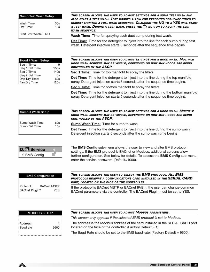
Auto Scrubber Control Panel 31
THIS SCREEN ALLOWS THE USER TO ADJUST MODBUS PARAMETERS.
This screen only appears if the selected BMS protocol is set to Modbus.
The address is the Modbus address of the card installed in the SERIAL CARD port located on the face of the controller. (Factory Default = 1).
The Baud Rate should be set to the BMS baud rate. (Factory Default = 9600).
MODBUS SETUP
Address: 1Baudrate 9600
THIS SCREEN ALLOWS THE USER TO SELECT THE BMS PROTOCOL. ALL BMS PROTOCOLS REQUIRE A COMMUNICATIONS CARD INSTALLED IN THE SERIAL CARD PORT, LOCATED ON THE FACE OF THE CONTROLLER.
If the protocol is BACnet MSTP or BACnet IP/Eth, the user can change common BACnet parameters via the controller. The BACnet Plugin must be set to YES.
BMS Configuration
Protocol: BACnet MSTPBACnet Plugin? YES
The BMS Config sub-menu allows the user to view and alter BMS protocol settings. If the BMS protocol is BACnet or Modbus, additional screens allow further configuration. See below for details. To access the BMS Config sub-menu, enter the service password (Default=1000).
D. Service
f. BMS Config
THIS SCREEN ALLOWS THE USER TO ADJUST SETTINGS FOR A SUMP TEST WASH AND ALSO START A TEST WASH. TEST WASHES ALLOW FOR EXPEDITED SEQUENCE TIMES TO QUICKLY MONITOR A FULL WASH SEQUENCE. CHANGING THE NO TO A YES WILL START A TEST WASH. DURING A TEST WASH, PRESS THE BUTTON TO ABORT THE TEST WASH SEQUENCE.
Wash Time: Time for spraying each duct sump during test wash.
Det Time: Time for the detergent to inject into the line for each sump during test wash. Detergent injection starts 5 seconds after the sequence time begins.
Sump Test Wash Setup
Wash Time: 30sDet Time: 10s
Start Test Wash? NO
THIS SCREEN ALLOWS THE USER TO ADJUST SETTINGS FOR A HOOD WASH. MULTIPLE HOOD WASH SCREENS MAY BE VISIBLE, DEPENDING ON HOW MAY HOODS ARE BEING CONTROLLED BY THE ASCP.
Sump Wash Time: Time for sump to wash.
Det Time: Time for the detergent to inject into the line during the sump wash. Detergent injection starts 5 seconds after the sump wash time begins.
Sump # Wash Setup
Sump Wash Time: 60sSump Det Time: 15s
THIS SCREEN ALLOWS THE USER TO ADJUST SETTINGS FOR A HOOD WASH. MULTIPLE HOOD WASH SCREENS MAY BE VISIBLE, DEPENDING ON HOW MAY HOODS ARE BEING CONTROLLED BY THE ASCP
Seq 1 Time: Time for top manifold to spray the filters.
Det Time: Time for the detergent to inject into the line during the top manifold spray. Detergent injection starts 5 seconds after the sequence time begins.
Seq 2 Time: Time for bottom manifold to spray the filters.
Det Time: Time for the detergent to inject into the line during the bottom manifold spray. Detergent injection starts 5 seconds after the sequence time begins.
Hood # Wash SetupSeq 1 Time: 0Seq 1 Det Time: 150sSeq 2 Time: 140sSeq 2 Det Time: 0sDrip Dry Time: 60sFan Dry Time: 120s

Auto Scrubber Control Panel32
THIS SCREEN ALLOWS THE USER TO ADJUST BACNET MSTP PARAMETERS.
This screen only appears if the selected BMS protocol is set to BACnet MSTP and BACnet Plugin = YES.
If a BACnet MSTP card has been installed, the default parameters can be changed via the controller display. Factory settings are shown in the screen to the left.
To view current parameters: 1. Power on controller and allow several minutes to initialize. 2. Go to BMS Config menu and view BACnet Read/Write screen. 3. Change Function to Read and Update? to YES.
Current BACnet MSTP parameters should now be displayed in the BACnet MSTP SETUP screen. If all values appear to be zeros, consult the factory. (Make sure you have allowed several minutes for the controller to initialize). Values may appear to be zero prior to setting the Function to READ.
To change BACnet MSTP parameters: 1. Power on controller and allow several minutes to initialize. 2. Go to BMS Config menu and view MSTP SETUP screen. 3. Move cursor to desired parameter by pressing the buttons. Press
to select the parameter to change. Press the buttons to adjust the parameter. Press to save adjusted value.
4. Once desired parameters have been entered, go to BACnet Read/Write screen. Change Function to Write and Update? to YES.
5. Reboot the controller by cycling power to the unit. Allow several minutes for the controller to initialize.
6. View MSTP parameters. If changed values did not save, contact the factory.
MSTP SETUP
Instance: 77000Baudrate 38400 MAC Addr: 0 MaxMasters: 127 MaxInfoFrames: 20
BACnet Read/Write
Function: ReadUpdate? Yes
*Cycle unit power to confirm write command.
THIS SCREEN ALLOWS THE USER TO ADJUST BACNET IP PARAMETERS.
This screen only appears if the selected BMS protocol is set to BACnet IP/Eth and BACnet Plugin = YES.
If a BACnet IP card has been installed, the default parameters can be changed via the controller display. The card is in DHCP mode from the factory. Once communication is established, the user can enter static IP parameters.
To view current parameters: 1. Power on controller and allow several minutes to initialize. 2. Go to BMS Config menu and view BACnet Read/Write screen. 3. Change Function to Read and Update? to YES.
Current BACnet IP parameters should now be displayed in the BACnet TCP/IP SETUP screen. If all values appear to be zeros, consult the factory. (Make sure you have allowed several minutes for the controller to initialize). *Values may appear to be zero prior to setting the Function to READ.
To change BACnet TCP/IP parameters: 1. Power on the controller and allow several minutes to initialize. 2. Go to BMS Config menu and view TCP/IP SETUP screen. 3. Move cursor to desired parameter by pressing the buttons. Press
to select the parameter to change. Press the buttons to adjust the parameter. Press to save adjusted value.
4. Once desired parameters have been entered, go to BACnet Read/Write screen. Change Function to Write and Update? to YES.
5. Reboot the controller by cycling power to the unit. Allow several minutes for the controller to initialize.
6. View TCP/IP parameters. If changed values did not save, contact the factory.
TCP/IP SETUP
Instance: 77000IP set by: DHCP IP: 128.2.104.134 Subnet: 255.255.000.000 Gatewy: 128.2.0.12
TCP/IP SETUP
DNS 1: 192.168.001.001DNS 2: 192.168.001.001Type: IP
BACnet Read/Write
Function: ReadUpdate? Yes*Cycle unit power to confirm write command.

Auto Scrubber Control Panel 33
THIS SCREEN ALLOWS THE USER TO ADJUST THE FAN OVERRIDE/FAN 100% SETTINGS.
Full Speed Override Duration: When the fans are running and the full speed override button is pressed, the fans will ramp up to full speed for this time limit. Once this time limit is reached, the fans will return to a speed based on hood temperature.
Full Speed Status: This will display whether the fans are in full speed mode. (ON = full speed button has been pressed, OFF = normal fan operation).
Full Speed Settings
Full Speed Override
Duration: 10min
Full Speed Status: OFF
THIS SCREEN ALLOWS THE USER TO ADJUST THE KITCHEN FIRE SETTINGS.
Exhaust fan operation during fire: During a kitchen fire, this will determine exhaust fan operation. (Default will be Fans On - Full Speed)
Supply fan operation during fire: During a kitchen fire, this will determine supply fan operation. (Default will be Fans Off). This will only be visible/adjustable IF there is at least one supply fan controlled by the ASCP system.
NOTE: Do not adjust these settings after a fire test has been completed.
Kitchen Fire Settings
Exhaust fan operation during fire:
Fans On - Full Speed
Supply fan operation during fire:
Fans Off
The Service Settings sub-menu allows the user to adjust fan operation, manually enable/disable inputs and outputs, hoods, and lights, calibrate sensors, create or restore user settings, and reset the alarm history log.
D. Service
g. Service Settingsa. Fan Operationb. I/O Manual Controlc. Hood Manual Controld. Light Manual Controle. Wash Manual Controlf. Sensor Calibrationg. User Save/Restoreh. Alarm History Reset
In Fan Operation, the user will be able to adjust full speed override settings, kitchen fire settings and exhaust/supply fan operation settings.D. Service
g. Service Settingsa. Fan Operation
THIS SCREEN ALLOWS THE USER TO ADJUST MINIMUM ON/MINIMUM OFF TIME FOR EXHAUST FANS.
Minimum On: This prevents all exhaust fans from shutting off for the maximum time selected. (Factory Default = 1 second)
Minimum Off: This prevents all exhaust fans from turning on for the minimum time selected. (Factory Default = 1 second)
Exhaust Fan Operation
Minimum On 1s
Minimum Off 1s
THIS SCREEN ALLOWS THE USER TO ADJUST THE SUPPLY FAN AIRFLOW PROVING DELAY
This screen will only be visible if the ASCP is controlling at least one supply fan and is configured for Airflow Proving.
Supply Fan Airflow Proving Delay: This will delay the time for the ASCP to allow for the supply fan to prove before logging a supply fan proving alarm. (Factory Default = 15 seconds)
Supply Fan Operation
Supply Fan Airflow
Proving Delay: 15s
WHEN A SUPPLY FAN IS ON AND TEMPERING, SETTINGS ON THIS SCREEN WILL PREVENT THE FANS FROM FALLING BELOW A SPECIFIC SPEED
This screen will only be visible if the ASCP is controlling at least one supply fan. Factory default minimum tempering speeds are 66.0%.
Supply Fan Operation
Minimum Tempering Setpoints
Supply Fan 1: 66.0% Supply Fan 2: 66.0% Supply Fan 3: 66.0% Supply Fan 4: 66.0%

Auto Scrubber Control Panel34
WHEN ONE SUPPLY FAN SPEED IS CONTROLLED VIA STATIC PRESSURE, THESE SETTINGS WILL BE VISIBLE AND ADJUSTABLE.
Supply fan speed can be controlled via a pressure differential between two spaces. Pressure setpoints and different PID loop settings can be adjusted with this option. It is recommended to contact the factory for assistance before adjusting these settings.
Supply Fan Operation
Pressure Setpoints
Setpoint: 0.000iwc
Pressure: 0.000iwc
Supply Fan Operation
Modulating Setup
Band: 50.0 Integration Time: 180s Derivative Time: 12s Dead Band OFF Above Set Point 1.0 Below Set Point 1.0
Manual Control: Allows the user to override the digital input for troubleshooting.Manual Position: The value to force the output to when in an override state.Status: The current state of the relay output.
Similar screens appear for all additional controller relay outputs.
Relay Output
Lights 1
Output Ch: NO1 Manual Control: OFF Manual Position: OFF Status: ON
Manual Control: Allows the user to override the analog output for troubleshooting.
Manual Value: The value to force the input to when in an override state.
Value: The current value of the analog output.
Similar screens appear for all additional controller analog inputs.
Analog Output
Exhaust Fan 1
Output Ch: Y1 Manual Control: OFF Manual Value: 0.00vdc Value: 5.00vdc
Manual Control: Allows the user to override the analog input for troubleshooting.Manual Value: The value to force the input to when in an override state.Value: The current value of the analog input.
Similar screens appear for all additional controller analog inputs.
Analog Input
Temperature Sensor 1
Input Ch: U1 Manual Control: OFF Manual Value: 0 Value: 70.0°F
Manual Control: Allows the user to override the digital input for troubleshooting.Manual Position: The value to force the input to when in an override state.Status: The current state of the digital input.
Similar screens appear for all additional controller digital inputs.
Digital Input
Remote On/Off
Input Ch: ID1 Manual Control: OFF Manual Position: CLOSED Status: Open
In I/O Manual Control, the user will be able to manually adjust inputs/outputs.
NOTE: The manual adjustment of these input and/or outputs should only be adjusted in the event of troubleshooting. We suggest these parameters only be changed with the advice of factory personnel.
D. Service
g. Service Settingsb. I/O Manual Control

Auto Scrubber Control Panel 35
In Hood Manual Control, the user will be able to manually turn on/off individual hood systems (turn on/off individual fans).D. Service
g. Service Settingsc. Hood Manual Control
In Light Manual Control, the user will be able to manually turn on/off individual light circuits.D. Service
g. Service Settingsd. Light Manual Control
The Wash Manual Control sub-menu allows the user to initiate individual hood and sump washes.D. Service
g. Service Settingse. Wash Manual Control
In Sensor Calibration, the user will be able to create temperature offsets for hood sensors and/or static pressure supply sensors, if equipped.D. Service
g. Service Settingsf. Sensor Calibration
Depending on how many hood systems there are, the user may see less/more hoods that can be controlled.
Hood Sys Manual On/Off
1. ON
2. OFF
3. ON
THIS SCREEN ALLOWS THE USER TO INITIATE INDIVIDUAL HOOD WASHES BY CHANGING THE NO TO A YES NEXT TO EACH AUTO SCRUBBER HOOD NUMBER. DEPENDING ON THE NUMBER OF LINKED AUTO SCRUBBER HOODS, THIS SCREEN MAY SHOW FEWER HOODS.
Wash Manual On/Off
Hoods
1: OFF2: OFF3: OFF4: OFF
THIS SCREEN ALLOWS THE USER TO INITIATE INDIVIDUAL SUMP WASHES BY CHANGING THE NO TO A YES NEXT TO EACH DUCT SUMP. DEPENDING ON THE NUMBER OF LINKED DUCT SUMPS, THIS SCREEN MAY SHOW FEWER SUMPS.
Sump Manual On/Off
Sumps
1: OFF2: OFF3: OFF4: OFF
Offset: This adjustable value can be used to calibrate the sensor with an offset value. (Factory Default = 0.0°F)
Value: This is the current value of the probe. (offset adjustment is added).
Similar screens are available for the remaining probes and static pressure sensor, if equipped.
Sensor Calibration
Temperature Sensor 1
Input Ch: U1 Offset: 0.0°F Value: 70.0°F
Depending on how many light circuits were configured on the system, the user may see less/more lights that can be controlled.
Light Manual On/Off
1. ON
2. OFF

Auto Scrubber Control Panel36
In User Save/Restore, the user will be able to save and restore the default parameters stored in memory.D. Service
g. Service Settingsg. User Save/Restore
If the user would like to save their settings, move the cursor to the SAVE position and change to ON. This will save all of the current parameters into memory as Service Settings. If the user would like to restore to these values at some point in the future, moving the cursor to the RESTORE position and selecting ON, will restore the controller to the user saved defaults.
User Save/Restore
Save? OFFRestore? OFFEnable Auto Restore? ON
In Alarm History Reset, the user will be able reset the alarm history log.D. Service
g. Service Settingsh. Alarm History Reset
The Configuration sub-menu allows the user to adjust an assortment of items including units (temperature), clock mode (12hr or 24hr), buzzer enable/disable, and allows for modifying passwords. However, these changes are to be completed under factory advisement only!
E. Manufacturer
a. Configuration
THIS SCREEN ALLOWS THE USER TO CLEAR THE ALARM FROM MEMORY.
If the user would like to clear the alarm log, move the cursor to the OFF position and change to ON.
Alarm History Reset
This will clear the Alarm history.
Continue? OFF
E. Manufacturer
The Manufacturer menu allows the user to access several sub-menus regarding controller configuration, I/O configuration, factory settings, controller initialization pages, and factory save/restore pages. These changes are to be completed under factory advisement only!
THIS SCREEN DISPLAYS AND ALLOWS ADJUSTMENT OF THE UNIT SETTINGS.
Unit Address: This is a reference to the unit address of the controller. It cannot be adjusted here.Temperature Units: The temperature units can be adjusted between Celsius and Fahrenheit.Force Clock Enable: This provides the ability to enable a clock for the controller without clock device on board. This should remain set at OFF.Clock Mode: 12 hour or 24 hour.Disable Buzzer: When turned to ON, the on-board buzzer is disabled. (Buzzer will still sound when gas is reset if the system was configured with the gas reset option).Startup Delay: This is the time delay added at start-up. This should remain set at 5 seconds.
ConfigurationUnit Address: 1 Temperature Units: °F Force Clock Enable: OFF Clock Mode: 12h Disable Buzzer: ON Startup Delay: 5s
THIS SCREEN DISPLAYS AND ALLOWS ADJUSTMENT OF THE BACKLIGHT TIMER (FACTORY DEFAULT = 300 SECONDS)
Configuration
Backlight Timer: 300s

Auto Scrubber Control Panel 37
THIS SCREEN DISPLAYS AND ALLOWS ADJUSTMENT OF ANALOG INPUT FILTERING
Similar screens appear for all additional controller analog inputs.Configuration
Analog Input FilteringEnable: OFF Input 1: 19s Input 2: 19s Input 3: 19s Input 4: 19s Input 5: 19s
THIS SCREEN PROVIDES A MEANS TO RESET MANUAL I/O.
Changing the Enable parameter to ON will reset all of the manual I/O settings after the time (Factory Default = 0 minutes expires).
Configuration
Manual Control Reset Enable: OFF Time: 0min
Passwords
Insert new passwordsService (PW1): 0000Manufacturer (PW2): 0000
THIS SCREEN ALLOWS THE USER TO CHANGE THE SERVICE (PW1) AND MANUFACTURER PASSWORD (PW2).
This default service (PW1) password is 1000.
THIS SCREEN DISPLAYS THE STATIC PRESSURE CONTROL SETTINGS.
This screen will only be visible if one supply fan is configured on the system and the supply fan speed is controlled via static pressure.
Modulating SetupSupply FanCntrl: REV PID Band: 50 Integration Time: 180s Derivative Time: 12s Min: -1000 Max: 0 Output Period: 500ms
THIS SCREEN DISPLAYS THE VFD MODBUS SETTINGS
This screen will only be visible if at least one Modbus VFD is controlled by the controller.
Configuration
Modbus Settings (VFDs)Port: FieldBus 2BaudRate: 19200Data: 8, None, 2

Auto Scrubber Control Panel38
These are examples of analog input screens. Similar screens appear for all additional controller analog inputs used.
Analog Input
Temp Sensor 1 En: ON Ch: U1 Normal PT1000
Offset: 0.0°F Value: 70.0°F
Analog Input
Temp Sensor 2
Out of Range Alarm Power Delay: 15s Run Delay: 15s
This is an example of a digital output screen. Similar screens appear for all additional controller digital inputs used.
Digital InputRemote On/Off Enable: ON Channel: ID1
Action: OPEN Delay: 0s Status: Open
This is an example of a relay output screen. Similar screens appear for all additional controller relay outputs used.
Relay Output
Lights 1 Enable: ON Channel: NO1
Status: OFF
The I/O Configuration sub-menu allows adjustment of all controller inputs and outputs. These screens are available to provide further information and allow for more adjustments on all inputs and outputs on the controller. However, these changes are to be done under factory advisement only!
E. Manufacturer
b. I/O Configuration
This is an example of an analog output screen. Similar screens appear for all additional controller analog outputs used.
Analog OutputExhaust Fan 1 Enable: ON Channel: Y1 Action: DIRECT Minimum: 0.00vdc Maximum: 10.00vdc Value: 0.00vdc

Auto Scrubber Control Panel 39
The Factory Settings sub-menu allows adjustments to the overall system setup. Adjusting any of these settings will affect basic functions of the controller. Upon adjusting any of these settings, the controller power should be cycled. Changes are to be done under factory advisement only!
E. Manufacturer
c. Factory Settings
This is an example of the first factory settings screen. Additional screens will be accessible.
Factory Settings 1
Brand: ACCUREX System Selection: S Interface: KEYPAD Hoods: 1 Sumps: 0 Exhaust Fans: 1
Shown here is the default installation screen. To initialize, move the cursor to NO using the enter button, press the up bottom to change to YES, and press the enter button.
Initialization
DEFAULT INSTALLATION Erase user settings and install global default values: NO
The Initialization sub-menu allows the user to reinitialize the controller. Reinitializing the controller will result in a non-customized controller and is to be done under factory advisement only!
E. Manufacturer
d. Initialization
The Factory Save/Restore sub-menu allows the user to save or restore the factory parameters. This is to be done under factory advisement only!E. Manufacturer
e. Factory Save/Restore
THIS SCREEN ALLOWS THE USER TO SAVE AND RESTORE THE FACTORY DEFAULT PARAMETERS STORED IN MEMORY.
The Factory Settings include the Factory default parameters and the unit setup code. If the user would like to restore to these parameters, move the cursor to the Restore position and change to ON.
Factory Save/Restore
Save? OFFRestore? OFFAuto Restore? No
THIS SCREEN ALLOWS THE USER TO CLEAR ALL SAVED DATA.Factory Delete
CLEAR ALL SAVED DATAFACTORY+USER: OFF

Auto Scrubber Control Panel40
Initial System Start-Up 1. Clean the control cabinet of any debris that may
have entered the cabinet during installation. 2. Add detergent to the detergent tank in the cabinet. 3. Turn power on to the control cabinet and fans (if
applicable). 4. Check electrical power is correct for hood controls,
lights (if applicable), and fans (if applicable). 5. Confirm the CAREL controller is operational; display
should be illuminated. 6. Check for any current system alarms, and correct if
present. 7. If system is controlling fans, turn the fans on via
the user interface. Check fan rotation and confirm exhaust and supply air volumes are correct (per design). After this has been completed, turn the fans off.
8. Turn on water supply, checking for any leaks before going further.
9. Prime the detergent pump. On the CAREL controller, navigate to the Service > Wash Settings > “Prime Detergent Pump” menu screen. Changing “OFF” to “ON” will start the detergent pump. This can also be done from the touchscreen (if provided).
Monitor the detergent line and press the ESC key once the detergent reaches the hot water line. Pressing ESC will stop the detergent pump.
10. If washing Auto Scrubber hoods, and the filter doors are not installed, install them now.
11. Run a test wash. On the CAREL controller, navigate to Service > Wash Settings > Hood Test Wash Setup menu screen. Adjust the times as necessary on the screen; change NO to YES. A test wash will start.
Ensure no leaks are present and water pressure is between 40 to 70 PSI while washing. At any time, the test wash can be aborted by pressing the ESC key.
Prime Detergent Pump
Prime the detergent pump? OFF Change NO to YES to start detergent pump.
Hood Test Wash SetupSeq Time: 30s Seq Det Time: 10s Drip Dry Time: 10s Fan Dry Time: 15sStart Test Wash? NO

Auto Scrubber Control Panel 41
A wash cycle can be initiated through a number of different options.
Wash by Button (Factory default = ON): A wash can be initiated through pressing either the “WASH” button (if equipped with a keypad) or by pressing “WASH ON/OFF” icon (if equipped with a touch screen).
Wash by Digital Input (Factory default = OFF): A wash can be initiated through engaging a configured digital input on controller. For the correct terminals to wire this digital input, please reference the Auto Scrubber Control Panel wiring diagram.
Wash by BMS Interface (Factory default = OFF): A wash can be initiated through engaging a BMS read/write point. Point lists can be found in the Auto Scrubber Control Panel IOM.
Wash by Scheduler (Factory default = OFF): A wash can be initiated daily at a specific time. If this option is enabled, this time can be field adjusted within the controller and touch screen, if equipped.
Wash by Auto Start (Factory default = ON): Each individual hood can be washed after that hood’s fan(s) has been running for a pre-determined time (factory default is 8 hours). This time setting and the maximum allowable auto start washes can be field adjusted within the controller and touch screen, if equipped.
NOTEAuto Start will only enable to Auto Scrubber hoods. It cannot be used to engage duct sump washes.
With exception to the Auto Start option, when a wash cycle has been initialized the Auto Scrubber hoods will be washed in order starting with Auto Scrubber hood 1. If duct sumps are also connected to this system, they will be washed in order after the Auto Scrubber hoods have been washed.
A wash cycle can be stopped at any time by pressing the “WASH” button (if equipped with a keypad) or by the “WASH ON/OFF” icon (if equipped with a touch screen).
An Auto Scrubber hood will be prevented, or abort operating in the wash cycle, should one of the following events occur:
• A kitchen fire alarm is detected.• A sensor linked to the Auto Scrubber hood fails.• The option to disable a wash during temperature
interlock is on (factory defaulted on) and a sensor linked to the Auto Scrubber hood exceeds the temperature interlock on setpoint.
• If the Auto Scrubber control panel is equipped with no fan controls (ASCP-W) and the fan input is triggered.
A fan exhausting an Auto Scrubber hood cannot be controlled by the user (turned on and off) while that Auto Scrubber hood is washing. If multiple Auto Scrubber hoods are employed, a fan linked to an Auto Scrubber hood which is not currently washing can be controlled by the user (turned on and off) as normal.
When duct sumps are washing, fans cannot run, unless:• A kitchen fire is detected• A sensor linked to any Auto Scrubber hood fails, or
any temperature sensor exceeds the temperature interlock on setpoint
• If the Auto Scrubber control panel is equipped with no fan controls (ASCP-W) and the fan input is triggered
NOTEDuct sumps may be controlled by this Auto Scrubber system. A duct sump is a grease reservoir installed in low points of grease duct which also requires routine wash downs.
Wash Operation (if equipped)
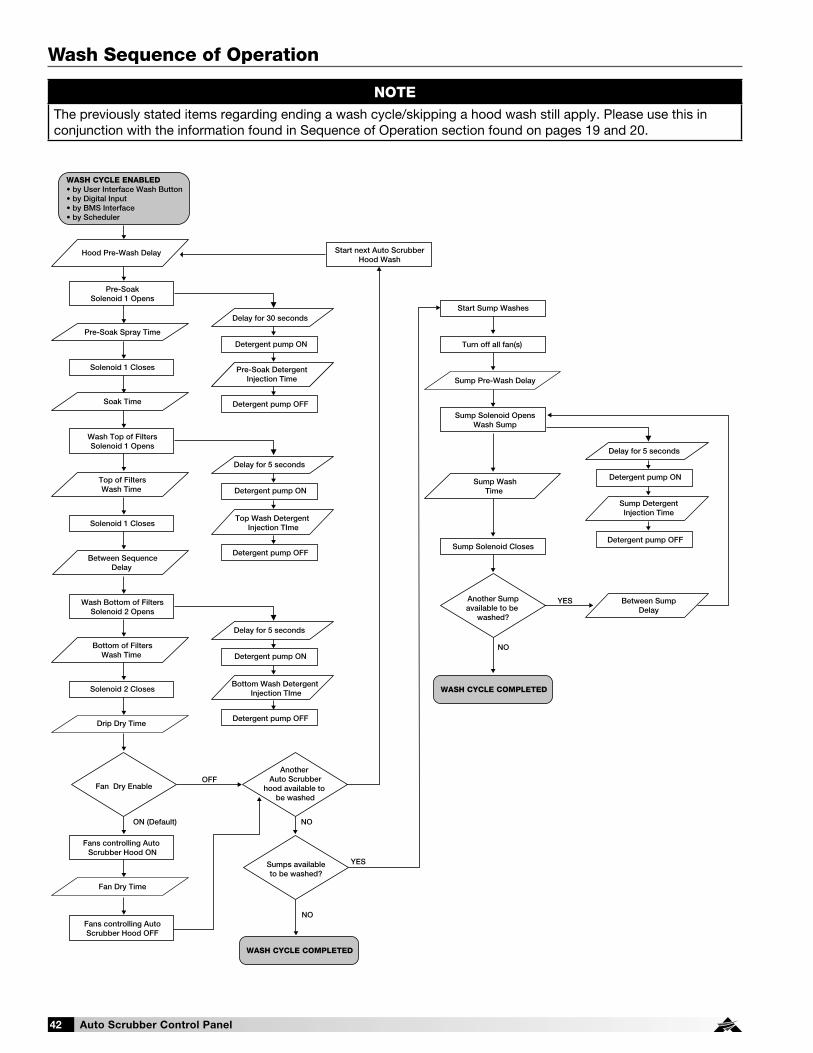
Auto Scrubber Control Panel42
NOTEThe previously stated items regarding ending a wash cycle/skipping a hood wash still apply. Please use this in conjunction with the information found in Sequence of Operation section found on pages 19 and 20.
Wash Sequence of Operation
Detergent pump ON
Solenoid 1 Closes
Detergent pump OFF
Pre-SoakSolenoid 1 Opens
Start next Auto ScrubberHood Wash
Wash Top of FiltersSolenoid 1 Opens
Fan Dry Enable
Sumps availableto be washed?
Another Auto Scrubber
hood available to be washed
WASH CYCLE ENABLED• by User Interface Wash Button• by Digital Input• by BMS Interface• by Scheduler
Hood Pre-Wash Delay
Delay for 30 seconds
Pre-Soak Spray Time
Soak Time
Sump Solenoid OpensWash Sump
Sump Pre-Wash DelayPre-Soak Detergent
Injection Time
Solenoid 1 Closes
Drip Dry Time
Top of FiltersWash Time
Between SequenceDelay
Fans controlling Auto Scrubber Hood ON
Start Sump Washes
Turn off all fan(s)
Fan Dry Time
Sump WashTime
Fans controlling AutoScrubber Hood OFF
OFF
NO
NO
YES
NO
YES
ON (Default)
Detergent pump ON
Detergent pump OFF
Delay for 5 seconds
Top Wash Detergent Injection TIme
Wash Bottom of FiltersSolenoid 2 Opens
Solenoid 2 Closes
Bottom of FiltersWash Time Detergent pump ON
Detergent pump OFF
Delay for 5 seconds
Bottom Wash Detergent Injection TIme
WASH CYCLE COMPLETED
WASH CYCLE COMPLETED
Detergent pump ON
Detergent pump OFF
Delay for 5 seconds
Between SumpDelay
Sump DetergentInjection Time
Another Sumpavailable to be
washed?
Sump Solenoid Closes

Auto Scrubber Control Panel 43
Detergent pump ON
Solenoid 1 Closes
Detergent pump OFF
Pre-SoakSolenoid 1 Opens
Wash Top of FiltersSolenoid 1 Opens
Fan Dry
HOOD WASH ENABLED BYAUTO START FEATURE• Auto Scrubber hood fans have been running for minimum time (Default = 480 minutes) and have been shut off
Hood Pre-Wash Delay
Soak Time
Delay for 30 seconds
Pre-Soak Spray Time
Pre-Soak DetergentInjection Time
Solenoid 1 Closes
Between Sequence Delay
Top of Filters Wash Time
Fans controlling Auto Scrubber Hood ON
Fan Dry Time
Fans controlling AutoScrubber Hood OFF
OFF
ON (Default)
Detergent pump ON
Detergent pump OFF
Delay for 5 seconds
Top Wash DetergentInjection Time
Wash Bottom of FiltersSolenoid 2 Opens
Solenoid 2 Closes
Drip Dry Time
Bottom of Filters Wash Time Detergent pump ON
Detergent pump OFF
Delay for 5 seconds
Bottom Wash DetergentInjection Time
AUTO START HOOD WASHCOMPLETED
Wash Sequence of Operation, continued
Wash Cycle Factory Default Times
Wash Cycle Stage
Time (seconds) Based on Filter Type
Baffle Grease-X-Tractor™
Energy RecoveryGrease Grabber™
Pre-Wash Delay 10 10
Pre-Soak Spray 60 60
Pre-Soak Detergent 30 30
Soak 60 60
Top Wash 120 350
Top Wash Detergent 60 150
Between Sequence Delay -5 -5
Bottom Wash 120 240
Bottom Wash Detergent 60 60
Drip Dry 60 60
Fan Dry 120 120
NOTEThe wash times are based on filter cleaning tests using filters coated heavily with oil and then baked-on using high temperatures. Actual required cleaning times will vary based on cooking equipment, fuel type, cooking frequency, and the food prepared. The table shown above should be used as a starting point. After a few weeks, the field can make adjustments as necessary based on the cleanliness of the filters upon removal/inspection.

Auto Scrubber Control Panel44
Keypad Navigation
When ‘BUTTON(S)’ are mentioned in the description below, we are referring to the ‘squares’ on the keypad. The following information details the Daily Operations of the ASCP keypad buttons and their functions.
HOODS/ALL HOODS - Momentarily pressing the ‘ALL HOODS’ button will turn on all hoods (fans) associated with the system. If all of the hoods (fans) are on, the background behind ‘ALL HOODS’ text will be dark. Pressing the same button again will turn off all hoods. If ‘HOODS’ is displayed instead of ‘ALL HOODS’, individual hood system control is available. Pressing the ‘HOODS’ button accesses another screen where individual hoods (fans) can be turned on and off. Press the button next to each hood system identified to enable/disable that hood/fan. Press the ‘MORE’ button (if applicable) to access additional hood systems. Press the ‘BACK’ button to return to the previous screen.
ALL LIGHTS/LIGHTS, if equipped - Momentarily pressing the ‘ALL LIGHTS’ button will activate all the lights for hoods associated with the system. If all hood lights are on, the background behind the ‘ALL LIGHTS’ text will be dark. Pressing the button again turns off the lights for all hoods. If ‘LIGHTS’ is displayed instead of ‘ALL LIGHTS’, individual light control is available. Pressing ‘LIGHTS’ button will access another screen where individual light circuits can be turned on and off. Press the light button next to each light circuit identified to enable/disable the lights for the hood(s). Press the ‘MORE’ button (if applicable) to access additional hood light circuits. Press the ‘BACK’ button to return to the previous screen.
MORE, if equipped - Momentarily pressing the ‘MORE’ button will navigate to an additional screen where the user will be able to enable/disable heating or cooling on the make-up air unit (if equipped with the auto tempering option) and/or reset the gas valve (if equipped with gas reset option).
BACK, if equipped - Momentarily pressing ‘BACK’ button will navigate to the previous screen.
AUTO TEMP, if equipped - Momentarily pressing the ‘AUTO TEMP’ button will enable the make-up air unit to heat and cool the air based on heating/cooling inlet air sensors. If auto tempering is on, the background behind ‘AUTO TEMP’ will be dark. Pressing the same button again will turn off auto tempering and therefore prevent your make-up air unit from heating/cooling the air.
GAS RESET, if equipped - Momentarily pressing the ‘GAS RESET’ button will open the electric gas valve and allow gas to flow to the appliance(s). If the gas valve is on, the background behind the ‘GAS RESET’ text will be dark. Once this is turned on, the gas reset will be permanently enabled. The gas valve will close only when a high temperature alarm (if equipped) or kitchen fire is detected.
MENUNAV
SYSTEM FAULT
MENUNAV
SYSTEM FAULT
ALL HOODS
ALL LIGHTS
MORE
AUTO TEMP WASH
BACK GAS RESET
NOTEImmediately after resetting gas valve, make sure to relight all standing pilot lights to prevent gas from flowing into the kitchen. As a reminder, the controller will beep three times upon resetting the value.
Display functionality and control:
To change the display contrast, hold the buttons next to the Alarm ! and Program icons simultaneously while pressing the buttons next to the and arrows. The down arrow will make the screen lighter and the up arrow will make the screen darker.
Upon any alarm, the ‘SYSTEM FAULT’ red LED light on the face of the keypad starts flashing. Once all alarms are corrected, this LED will stop flashing and no longer be illuminated.
Through the middle of the screen, system status messages will be displayed as a reference. These system statuses will include:
• Current alarms• Time remaining on fan 100% override timer (if on)• Hoods that are on by temperature interlock• Hoods that are on by the user interface• Lights that are on by the user interface• Fans that are in balancing mode
The keypad also includes indicators next to buttons that correspond to help the buttons on the controller. These can be used to navigate through the controller using the keypad. To access the main menu, simply press and hold the button next to the Program icon for five seconds or until the screen changes to the main menu.
WASH, if equipped - Momentarily pressing the 'WASH' button will engage a wash cycle. If a wash cycle is currently occurring, pressing this button momentarily will stop the wash cycle.

Auto Scrubber Control Panel 45
Touch Screen Navigation
Momentarily press or tap to access the menu or enable or disable the action of the associated icon. All icons surrounded by blue are momentarily push buttons.
ALL LIGHTS ON/OFF (if equipped) - turns on all hood lights associated with the system. When all hood lights are activated, the light bulbs within the icon illuminate.
Tapping the icon again will turn off the lights.
INDIVIDUAL LIGHT ON/OFF (if equipped) - access a secondary screen menu whereby control over individual light circuits is available. Tap the icon next to each light
circuit identified to enable/disable. Press the back arrow to return to the home screen.
ALL HOODS ON/OFF (if equipped) - turns on all hoods (fans) associated with the system. If all hoods are operating, the fan propellers in the icon starts spinning. Press
again to turn off all hoods.
INDIVIDUAL HOOD SYSTEMS ON/OFF (if equipped) - allows control over multiple fans that are not tied to the same hood. Access to a secondary menu screen allowing the
ability to enable/disable individual hood systems. Press the back arrow to return to the home screen.
100% OVERRIDE ON/OFF (if equipped) – forces the fans that are currently operating to full speed. (This icon will only be visible if at least one exhaust fan is running).
When turned on, the third bar on the icon blinks green. Fans will return to the speed determined by the hood temperature after the timer has expired (default time is 10 minutes). Pressing this icon when 100% OVERRIDE is on, will also return the fans to the speed determined by the hood temperature.
AUTO TEMPERING ON/OFF (if equipped) - enables the make-up air unit to automatically heat and/or cool the air based on the inlet air temperature. When auto tempering is
enabled, the thermometer illuminates. Pressing the icon again disables auto tempering, the make-up air unit’s heat and/or cooling capabilities.
GAS RESET ON/OFF (if equipped) – turns on the gas to the appliance(s); opens the electric gas valve. The gas valve will close (gas will be shut off) if a fire occurs or high temperature is
detected in any hood. When the gas is on, the icon will show ‘ON’.
WASH ON/OFF - used to start and stop a wash cycle for all Auto Scrubber hoods and duct sumps.
PCU FILTER STATUS (if equipped) – indicates loaded/clogged filter(s) in the Pollution Control Unit (PCU). If filters are satisfactory, filter image will remain gray.
The image of the affected filter(s) will flash red. Once clogged, the filter(s) must be replaced.
TEMP INTERLOCK INDICATOR (if equipped) – indicates if at least one hood is operating in temperature mode. If the fan(s) were not turned on via the ALL
HOODS ON/OFF or INDIVIDUAL HOOD SYSTEMS ON/OFF and the temperature in the hood is above the temperature interlock set point, this icon will animate. The fan(s) will continue to operate until the temperature is below the set point for the amount of time in the temperature interlock settings.
ENERGY SAVINGS INDICATOR (if equipped)– this appears if at least one fan is operating. Displays real-time electrical energy savings due to reducing fan speeds.
HELP – this will display a help menu and navigation tips.
NAVIGATION BAR (arrow at bottom of the screen) – pulls up the hidden NAVIGATION
menu allowing access to alarms, home, and settings/configuration/information screens. This is available on every screen.
NOTEThis percentage does not take into consideration additional savings from lowering the airflow requirements for heated and/or cooled make-up air and building HVAC air.

Auto Scrubber Control Panel46
The alarm icon directs you to the alarms screen. This
icon will illuminate red and blink when an alarm has
been triggered.
The middle icon directs you to the home screen.
The icon on the far right allows navigation to the settings/configuration/information menu screen.
Pressing either of the black arrows to the right and left of these three buttons will hide the navigation menu bar.
Settings• Fire
Service Password Screen
Active Alarms Example
Lights Out in Fire: Changing this setting to ON will turn all hood lights off during a fire.
Exhaust On in Fire: Changing this setting to ON will turn all exhaust fans controlled by the system to full speed during a fire.
Supply On in Fire: Changing this setting to ON will turn all supply fans controlled by the system to full speed during a fire.
Electric Gas Valve Present: Changing this setting to ON will enable the gas reset option; provides a means of manually resetting an electric gas valve.
NOTEThe Service Password must be entered to access the SETTINGS, CONFIGURATION and INFORMATION screen. The default service password is 1000.
General InformationAny field surrounded by a box with a white fill indicates that it is editable.
If an editable field displays a numerical value and the user taps the field, a number keypad will display. After entering the desired value, press the Enter button.
If the editable field is an alphanumeric value, a standard keyboard will display. After entering the desired value, press the Enter button.
The field may also display a multiple choice ON/OFF, or a checkmark box. For the ON/OFF fields, press the box opposite of the checked box to change the option from either OFF to ON or visa versa. For checkmark boxes, to unlink an item momentarily press on the box to remove the checkmark or conversely, to link an item, press the box to add a checkmark.

Auto Scrubber Control Panel 47
Fan Name: User can adjust the “nickname” of the fan to something such as “FRYER FAN”.
Design CFM: Set from factory (full speed, exhaust airflow rate).
Current CFM: Current CFM exhausted from the fan.
Low Temp Setpoint: Temperature at or below this setpoint will cause the fan to run at the low speed.
High Temp Setpoint: Temperature at or above this setpoint will cause the fan to run at the high speed.
Low Speed: Lowest fan operational speed.
Highest Speed: Highest fan operational speed.
Fan Name: User can adjust the “nickname” of the fan to something such as “HOOD1 SUPPLY”.
Design CFM: Set from factory (full speed, supply airflow rate).
Current CFM: Current CFM supplied from the fan.
Low Speed: Lowest fan operational speed.
Highest Speed: Highest fan operational speed.
Light Circuit Name: User can adjust the nickname of each light circuit.
Temperature Interlock Enabled: User can enable or disable temperature interlock.
Temperature On Setpoint: The temperature at which the fan(s), if off, will automatically turn on.
Temperature Off Setpoint: Temperature at which the fan(s) will turn off once the time delay setpoint is reached - assuming the fan(s) have not been turned on manually by the touch screen.
Time Delay Off Setpoint: Amount of time the fan(s) need to be below the temperature off setpoint before the fan(s) will shut off.
100% Override Button Timer: Amount of time the fans are at full speed when the 100% override button is pressed.
Settings - continued• Exhaust Fans
• Supply Fans
• Lights
• Temperature Interlock & Override
NOTEThe fans will modulate speed when the temperature is between the low and high temp setpoints.
WARNINGTemperature interlock is a code requirement in most jurisdictions. DO NOT DISABLE THIS OPTION UNLESS INSTRUCTED BY THE FACTORY OR AUTHORITY HAVING JURISDICTION. DO NOT CHANGE THIS SETTING ONCE THE SYSTEM HAS PASSED INSPECTION.

Auto Scrubber Control Panel48
To update wash settings, press on the corresponding buttons under “SETTINGS”. To start or alter test wash settings, press on the corresponding button under “TEST WASH”. To prime the detergent pump, press the corresponding button under “PRIME DETERGENT PUMP”.
Wash by Button: Enable or disable wash by button option.
Wash by Digital Input: Enable or disable wash by digital input option.
Wash by BMS: Enable or disable wash through BMS option.
Wash by Scheduler: Enable or disable wash through daily scheduled time option.
Wash by Auto Start: Allow wash to automatically start after fan serving hood shuts off.
Current Date/Time: Current date and time.
Daily Wash Start Time: Enable wash to start at specific time every day.
Minimum Fan Run Time: Minimum amount of time fan exhausting Auto Scrubber hood has to be running before hood will be set up to automatically wash after fan shuts off.
Maximum Number of Daily Washes: Maximum number of wash cycles that can be initiated through the Auto Start feature.
Settings - continued• General Wash Settings
• Wash Enable Setup
• Wash Scheduler Settings
• Auto Start Wash Settings

Auto Scrubber Control Panel 49
Pre Wash Delay: Count down time until wash begins after initiated.
Pre Soak Spray: Time allotted to soaking the filters.
Pre Soak Detergent Time: Time allotted to injecting detergent into the line while soaking the filters. This detergent injection begins 30 seconds after the pre-soak spray has begun.
Soak Time: Time allotted to allowing the detergent and water to set on/in filters and soak.
Between Sequence Delay: Time between the first and second sequence (top and bottom manifold).
Disable Wash during Temperature Interlock: By selecting ON, a hood that is currently washing will abort the wash cycle of that hood and the hood will be prevented from being washed until temp interlock is no longer present for that hood section.
Fan Dry Enable: If enabled, this will turn fans on after wash cycle is completed to draw out leftover moisture and dry plenum of hood.
Enable Cold Water Mist During Fire: By selecting ON, a hood will enable the cold water mist during a kitchen fire.
Last Completed Hood Wash: A date and time stamp of the last completed Auto Scrubber hood washed.
Settings - continued• Hood Wash Setup
Pre Wash Delay: Count down time until sump wash begins after initiated.
Between Sequence Delay Time: Time between the sumps (if multiple sumps are present).
Sump Wash Time: Time for sump to wash.
Detergent Injection Time: Time for detergent to inject into line during the sump wash. Detergent injection starts 5 seconds after the sump wash time begins.
Enter into Hood Test Wash setup screens by pressing “HOOD TEST WASH SETUP” button. Enter into Sump Test Wash setup screens by pressing “SUMP TEST WASH SETUP” button. Start a test wash by pressing the “START TEST WASH” button. Once a test wash is started, press the “STOP WASH” button to stop a test wash prematurely.
• Sump Wash Setup
• Sump # Settings
• Test Wash Setup

Auto Scrubber Control Panel50
Sequence Time: Time for each manifold (top and bottom) to spray.
Detergent Injection Time: Time for the detergent to inject into the line for each manifold (top and bottom). Detergent injection starts 5 seconds after the sequence time begins.
Drip Dry Time: Time after both manifolds are done spraying (time before fan dry, if enabled).
Fan Dry Time: Time allotted to running the fan after a hood wash is done drip drying.
Settings - continued• Hood Test Wash Setup
Sump Wash Time: Time for spraying each duct sump during test wash
Detergent Injection Time: Time for the detergent to inject into the line for each sump during test wash. Detergent injection starts 5 seconds after the sequence time begins.
• Sump Test Wash Setup
Press the “STOP PUMP” button to stop the detergent pump from priming.
• Prime Detergent Pump
Configuration• Date / Time
• Hoods
Adjust Date: Adjust the date. DD/MM/YY format.
Adjust Time: Adjust the time.
To store the adjusted date and time in both the touch screen and the main controller, press ‘UPDATE DATE/TIME’.
Associated Temperature Sensors: Link sensors to the hood by checking or unchecking the boxes.
Associated Exhaust Fans: Link exhaust fans to the hood by checking or unchecking boxes.
Associated Supply Fans: Link supply fans to the hood by checking or unchecking the boxes.
Hood System: Based on the selections on the screen, this provides the hood system number that the hood currently is linked to.
Auto Scrubber Hood #: Based on the factory settings, this number is provided if the current hood is an Auto Scrubber hood, and if it is, what number Auto Scrubber hood.
Press the “AUTO SCRUBBER HOOD # WASH SETTINGS” button to navigate to a screen where the individual hood wash settings can be adjusted.

Auto Scrubber Control Panel 51
Configuration - continued• Auto Scrubber Hood # Wash Settings
• Hood System Scheduling
• Fan Balancing
Sequence 1 Time: Time for top manifold to spray the filters.
Sequence 1 Detergent Time: Time for the detergent to inject into the line during the top manifold spray. Detergent injection starts 5 seconds after the sequence time begins.
Sequence 2 Time: Time for bottom manifold to spray the filters.
Sequence 2 Detergent Time: Time for the detergent to inject into the line during the bottom manifold spray. Detergent injection starts 5 seconds after the sequence time begins.
Drip Dry Time: Time after both manifolds are done spraying (time before fan dry, if enabled).
Fan Dry Time: Time allotted to running the fan after a hood wash is done drip drying.
Wash Count: Number of completed washes for hood.
Wash Count During Low Detergent Alarm: Number of washes per hood during a low detergent alarm.
Allows the user to set up a scheduled time each hood system should turn on/off during the day. Can adjust the occurrence, time on and time off. In order for the scheduling to be used, the Enable check box must be selected.
Balancing allows the user to easily balance the exhaust and supply fans.
Mode of Operation: Normal Operation
Fans operate based off the fans on/off buttons and temperatures.
Mode of Operation: Balance Minimum
Forces the fans on and at the speed shown in the minimum speed box.
Mode of Operation: Balance Maximum
Forces the fans on and at the speed shown in the maximum speed box.
Minimum Speed: Adjust the minimum speed as necessary for the design of the system.
Maximum Speed: Adjust the maximum fan speed as necessary for the design of the system.
NOTEMake sure to return the mode of operation to ‘NORMAL OPERATION’ when balancing is complete. If the mode of operation is left in Balance Minimum or Balancing Maximum, the fan(s) will not turn off.
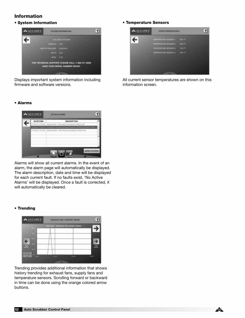
Auto Scrubber Control Panel52
Information• System Information
Displays important system information including firmware and software versions.
• Alarms
• Temperature Sensors
• Trending
Alarms will show all current alarms. In the event of an alarm, the alarm page will automatically be displayed. The alarm description, date and time will be displayed for each current fault. If no faults exist, ‘No Active Alarms’ will be displayed. Once a fault is corrected, it will automatically be cleared.
All current sensor temperatures are shown on this information screen.
Trending provides additional information that shows history trending for exhaust fans, supply fans and temperature sensors. Scrolling forward or backward in time can be done using the orange colored arrow buttons.

Auto Scrubber Control Panel 53
Troubleshooting
Problem: Smoke spilling out of hoods at 100% operation (ASCP-V only)
Maximum fan speed has been scaled down from 100%
Increase exhaust fan maximum speed to 100%. Refer to information provided on page 28 to adjust setpoints.
Improper hood design Check hood overhang, cross drafts or proper make-up air
Problem: Smoke spilling out of hood(s)
Fan minimum speed is set too low Increase exhaust fan minimum speeds (ASCP-V only). Refer to information provided on page 28 to adjust setpoints.
Improper hood design Check hood overhang, cross drafts or proper make-up air
Problem: Fans do not turn up to maximum speed (ASCP-V only)
Dirty temperature sensor Clean grease from temperature sensor
High temperature set point is set too high Decrease the high temperature set point (115ºF default). Refer to information provided on page 28 to adjust set points.
Fans are in balancing mode Check balancing menus to determine if fans are in balancing mode. Refer to information provided on page 28 to adjust set points.
Fan 100% button is activated Check 100% timer setting
Problem: Fans do not turn down to minimum speed (ASCP-V only)
Dirty temperature sensor Clean grease from temperature sensor
Low temperature set point is set too low Increase the low temperature set point (90ºF). Refer to information provided on page 28 to adjust set points.
Fans are in balancing mode Check balancing menus to determine if fans are in balancing mode
Problem: Exhaust fan on and supply fan off
Broken supply fan belt Replace fan belt
Fire fault Check fire suppression microswitch connection
Exhaust fan VFD in local control Put exhaust fan VFD back into remote control
Supply fan breaker tripped Reset breaker
Problem: Supply fan on and exhaust fan off
Broken exhaust fan belt Replace fan belt
Supply fan VFD in local control Put supply fan VFD back into remote control
Exhaust fan breaker tripped Reset breaker
Problem: Fan wheel rotates in wrong direction
Fan wiring incorrect Switch any two power wires on the fan motor OR change PAR b1-14 from 00 to 01 on the VFD (if ASCP-V with factory provided VFDs)
Problem: 100% override does not increase exhaust speed (ASCP-V only)
Exhaust already at 100% due to hood temperature
Proper operation
Problem: Fan button is on, but fans do not turn on
Broken fan belt Replace fan belt
VFD fault Check VFD for faults
Problem: Fan button is off, but the fans will not turn off
ASCP is operating in temperature interlock mode. Temperature interlock indicator on keypad or touch screen will be on.
The temperature in the hood is still above the temperature interlock off set point. It will automatically turn off once below the setpoint and off delay time has expired.
Problem: Hood light(s) button on, but actual lights are not on
Light bulbs are burned out Replace hood light bulbs
Bad wiring connection Verify lights are wired to the correct terminals. Refer to the lights wiring instructions on page 8
Problem: Fans do not turn on automatically
Temperature interlock is disabled Enable the temperature interlock option (default is enabled) in the set point menu
Interlock set point set too high Decrease the temperature interlock on set point (refer to page 28)

Auto Scrubber Control Panel54
Troubleshooting
Problem: Pressure sensor alarm
Kinked hose Remove kink or replace hose
Controlled space not holding pressure Adjust the static pressure set point or change supply mode
Problem: Kitchen fire alarm
Kitchen fire is in progress; fire suppression has dumped
Evacuate the facility immediately and contact your local fire department.
Fire system microswitch is in the fire position Check the fire suppression microswitch connections
Problem: Temperature sensor input failure
Faulty wiring to temperature sensor Check wiring at ASCP control panel (refer to page 10) and at hood connection
Incorrect programming Check the temperature sensor settings (consult factory).
Dirty/Faulty sensor Clean or replace sensor
Problem: Exhaust / supply fan alarm - general
Look at VFD display for fault identification, or attempt reset overload on fan motor starter
With ASCP-V panels with factory provided VFDs, refer to the Yaskawa Quick Start Guide for fault and tips to correct. Once corrected, recycle power to the VFD via the breaker. Wait until all power is drained from the VFD before turning power back on.
Problem: Exhaust / supply VFD fault. Fault code “CE” or “CALL” (ASCP-V only)
Faulty communication wiring between VFD and controller
Check all communication wiring between VFD and the ASCP controller. Confirm all wiring corresponds with factory wiring diagram.
Incorrect programming in VFD Check VFD communication parameters
Incorrect programming in ASCP controller Check ASCP controller factory settings pages (consult factory)
Problem: Fan is making grinding/winding noise and/or appears to struggle to operate (ASCP-V only)
Carrier frequency on VFD needs adjustment Change parameter C6-02 on the VFD anywhere between values 01 and 06, testing the fan at maximum speed with each adjustment. Set this parameter at whichever value corrects this issue.
Issue with fan bearings/drive components Check fan bearings and fan drive components. Replace if necessary.
Problem: Keypad connected via factory-supplied RJ25 cable to J10 port on main controller, but keypad displays a blank screen
ASCP controller/panel is off Turn panel on
Contrast on keypad has been adjusted Press and hold top left button and top middle hidden button on the keypad overlay. While holding these buttons down, repeatedly press the bottom left button (makes the screen darker) or bottom right button (makes the screen lighter) until suitable to read.
Faulty keypad Replace keypad
Problem: Touch screen displaying “Communication Error” screen
Communication to touch screen is faulty Check communication wiring from bottom of touch screen (-, +, O) and confirm this is connected back to main CAREL® controller on the J25 port (-, +, O)
Problem: Fault light flashing red on the keypad; alarm button red on touch screen
Fault has been detected in ASCP system Clear the faults. If the faults will not clear, there is a current fault on system. Correct the fault and then proceed to clear the fault.
Problem: Pollution control unit (PCU) filter status alarm
PCU filter is clogged/full Replace filter
Problem: An Auto Scrubber hood is not washing routinely (wash cycle not activating).
Is the system in fault? Fire, high temperature and sensor faults will prevent a wash from starting. Correct these faults.
Are you relying on the hood to wash manually?
In the control panel Wash Enable option, verify the setting for “Wash by Button” is set to ON. Ensure (recommended after start up) the kitchen employees are pressing the WASH button daily.

Auto Scrubber Control Panel 55
Variable Frequency Drive (VFD) Information - if equipped
Yaskawa V1000 (200-230 VAC and 460 VAC) or Yaskawa A1000 (575 VAC) variable frequency drives (VFDs) will be provided if the ASCP-V is configured to use VFDs to control the fans. These drives will come programmed from the factory, and little to no adjustment will be necessary in most cases. For more in-depth information on wiring and programming these drives, please utilize the Quick Start Guide provided with the package. This quick start guide and other technical manuals can also be found on the Yaskawa website at www.yaskawa.com.
Parameter Description Default Value Factory Adjustment
b1-01 Reference Source Speed Control Method 01 02
b1-02 Run Source – Start/Stop Control Method 01 02
b1-07 LOCAL/REMOTE Run Selection 00 01
b1-17 Run Command at Power Up 00 01
C1-01 Acceleration Time 1 10.00 seconds 30.00 seconds
C1-02 Deceleration Time 1 10.00 seconds 30.00 seconds
E1-01 Input Voltage Dependent on drive type Dependent on motor voltage*
E2-01 Motor Rated Current Dependent on drive type Dependent on motor FLA (full load amperage)*
H5-01 Drive Node Address 1F Dependent on VFD address*
H5-02 Communication Speed Selection 03 04
H5-09 CE Detection Time 2.0 seconds 10.0 seconds
L2-01 Momentary Power Loss Operation Selection 00 02
L5-01 Number of Auto Restart Attempts 00 10
*See ASCP wiring diagram for more information.
Resetting the VFD Faults
Upon a VFD fault, first determine the cause of the fault and correct. Typically, if the drive detects a fault, it will remain inoperable until that fault has been corrected and the drive has been reset.
Once a fault has been corrected, the easiest way to clear the displayed fault on the VFD is to shut off power to the drive from the power source (breaker). Wait for the VFD to fully discharge and then restore the power.
Upon correcting a minor fault, recycling power may not be necessary. Simply press RESET , then press LORE twice.
Once the fault has been corrected and the drive has been reset, the main controller alarm should automatically be cleared. See page 24 for details.

Auto Scrubber Control Panel56
Model V1000
Model A1000
Changing ParametersStep 1: V1000 Digital Operator power-up state. ESC
ALMDRV FOUT
REV
STOP
ENTER
LORE
RUN
RESET
F 0.00
Step 2: Select Parameter Menu
Press two times until the digital operator show the parameter menu (PAr) then press ENTER .
ESC
ALMDRV FOUT
REV
STOP
ENTER
LORE
RUN
RESET
PAr
Step 3: Select Parameter
Press RESET to select the digit you would
like to change. Next use and to select the parameter group, sub-group or number.
Once the parameter you wish to change is displayed on the screen and the digit furthest to the right is flashing, press ENTER .
ESC
ALMDRV FOUT
REV
STOP
ENTER
LORE
RUN
RESET
C 1-01
Step 4: Change Parameter Value
Press RESET to select the digit of the parameter value you would like to change.
Modify the parameter value using and and press ENTER to save the new value.
ESC
ALMDRV FOUT
REV
STOP
ENTER
LORE
RUN
RESET
0010.0
Step 2: Select Parameter Menu
Press two times until the digital operator shows the programming menu, then press ENTER .
ESC
F1 F2
STOP
ENTER
LORE
RUN
RESET
DIGITAL OPERATOR JVOP-180 ALM
- MODE - PRG Programming
HELP FWD DATA
Step 3: Select Parameter
Press RESET to select the digit you would
like to change. Next use and to select the parameter group, sub-group or number.
One the parameter you wish to change is displayed on the screen and the digit furthest to the right is flashing, press ENTER .
ESC
F1 F2
STOP
ENTER
LORE
RUN
RESET
DIGITAL OPERATOR JVOP-180 ALM
- PRMSET - PRG
C1-01= 10.0 sec Accel Time 1
FWD
Step 4: Change Parameter Value
Press RESET to select the digit of the parameter value you would like to change.
Modify the parameter value using and and press ENTER to save the new value.
ESC
F1 F2
STOP
ENTER
LORE
RUN
RESET
DIGITAL OPERATOR JVOP-180 ALM
- PRMSET - PRG Accel Time 1
C1-01= 0010.0 sec ( 0 . 0 - 6 0 0 0 . 0 ) “10.0 sec”
FWD
Monitor Motor Frequency and Motor CurrentStep 1: V1000 Digital Operator power-up state: ESC
ALMDRV FOUT
REV
STOP
ENTER
LORE
RUN
RESET
F 0.00
Step 2: Output Frequency
Press until the FOUT LED turns on. The display now shows the actual drive output frequency in hertz (Hz).
ESC
ALMDRV FOUT
REV
STOP
ENTER
LORE
RUN
RESET
16.56
Step 3: Motor Current
Press again will show the motor output current. The ‘A’ behind the value means ‘Amps’.
ESC
ALMDRV FOUT
REV
STOP
ENTER
LORE
RUN
RESET
0.8A
Monitor Motor Frequency and Motor CurrentWith the drive running, press until reaching the Monitor Menu. This will display output frequency and amperage of the motor.
ESC
F1 F2
STOP
ENTER
LORE
RUN
RESET
DIGITAL OPERATOR JVOP-180 ALM
- MODE - DRV Rdy Fref Ref (AI )
U1-01= 60.00 HzU1-02 60.00 Hz
U1-03 2.07A
JOG FWD
RSEQRREF
Changing ParametersStep 1: A1000 Digital Operator power-up state.
ESC
F1 F2
STOP
ENTER
LORE
RUN
RESET
DIGITAL OPERATOR JVOP-180 ALM
- MODE - DRV Rdy Fref Ref (AI )
U1-01= 0.00 HzU1-02 0.00 Hz
U1-03 0.00A
JOG FWD
RSEQRREF
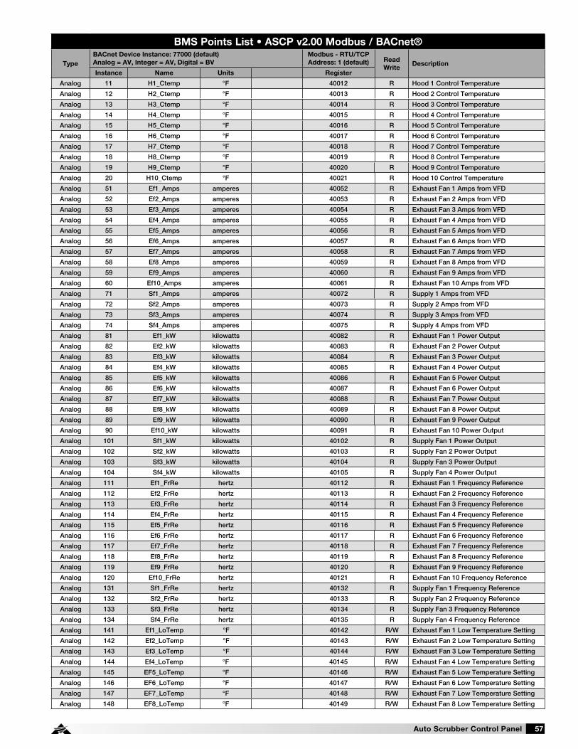
Auto Scrubber Control Panel 57
BMS Points List • ASCP v2.00 Modbus / BACnet®
Type
BACnet Device Instance: 77000 (default)
Analog = AV, Integer = AV, Digital = BV
Modbus - RTU/TCP
Address: 1 (default) Read
WriteDescription
Instance Name Units Register
Analog 11 H1_Ctemp °F 40012 R Hood 1 Control Temperature
Analog 12 H2_Ctemp °F 40013 R Hood 2 Control Temperature
Analog 13 H3_Ctemp °F 40014 R Hood 3 Control Temperature
Analog 14 H4_Ctemp °F 40015 R Hood 4 Control Temperature
Analog 15 H5_Ctemp °F 40016 R Hood 5 Control Temperature
Analog 16 H6_Ctemp °F 40017 R Hood 6 Control Temperature
Analog 17 H7_Ctemp °F 40018 R Hood 7 Control Temperature
Analog 18 H8_Ctemp °F 40019 R Hood 8 Control Temperature
Analog 19 H9_Ctemp °F 40020 R Hood 9 Control Temperature
Analog 20 H10_Ctemp °F 40021 R Hood 10 Control Temperature
Analog 51 Ef1_Amps amperes 40052 R Exhaust Fan 1 Amps from VFD
Analog 52 Ef2_Amps amperes 40053 R Exhaust Fan 2 Amps from VFD
Analog 53 Ef3_Amps amperes 40054 R Exhaust Fan 3 Amps from VFD
Analog 54 Ef4_Amps amperes 40055 R Exhaust Fan 4 Amps from VFD
Analog 55 Ef5_Amps amperes 40056 R Exhaust Fan 5 Amps from VFD
Analog 56 Ef6_Amps amperes 40057 R Exhaust Fan 6 Amps from VFD
Analog 57 Ef7_Amps amperes 40058 R Exhaust Fan 7 Amps from VFD
Analog 58 Ef8_Amps amperes 40059 R Exhaust Fan 8 Amps from VFD
Analog 59 Ef9_Amps amperes 40060 R Exhaust Fan 9 Amps from VFD
Analog 60 Ef10_Amps amperes 40061 R Exhaust Fan 10 Amps from VFD
Analog 71 Sf1_Amps amperes 40072 R Supply 1 Amps from VFD
Analog 72 Sf2_Amps amperes 40073 R Supply 2 Amps from VFD
Analog 73 Sf3_Amps amperes 40074 R Supply 3 Amps from VFD
Analog 74 Sf4_Amps amperes 40075 R Supply 4 Amps from VFD
Analog 81 Ef1_kW kilowatts 40082 R Exhaust Fan 1 Power Output
Analog 82 Ef2_kW kilowatts 40083 R Exhaust Fan 2 Power Output
Analog 83 Ef3_kW kilowatts 40084 R Exhaust Fan 3 Power Output
Analog 84 Ef4_kW kilowatts 40085 R Exhaust Fan 4 Power Output
Analog 85 Ef5_kW kilowatts 40086 R Exhaust Fan 5 Power Output
Analog 86 Ef6_kW kilowatts 40087 R Exhaust Fan 6 Power Output
Analog 87 Ef7_kW kilowatts 40088 R Exhaust Fan 7 Power Output
Analog 88 Ef8_kW kilowatts 40089 R Exhaust Fan 8 Power Output
Analog 89 Ef9_kW kilowatts 40090 R Exhaust Fan 9 Power Output
Analog 90 Ef10_kW kilowatts 40091 R Exhaust Fan 10 Power Output
Analog 101 Sf1_kW kilowatts 40102 R Supply Fan 1 Power Output
Analog 102 Sf2_kW kilowatts 40103 R Supply Fan 2 Power Output
Analog 103 Sf3_kW kilowatts 40104 R Supply Fan 3 Power Output
Analog 104 Sf4_kW kilowatts 40105 R Supply Fan 4 Power Output
Analog 111 Ef1_FrRe hertz 40112 R Exhaust Fan 1 Frequency Reference
Analog 112 Ef2_FrRe hertz 40113 R Exhaust Fan 2 Frequency Reference
Analog 113 Ef3_FrRe hertz 40114 R Exhaust Fan 3 Frequency Reference
Analog 114 Ef4_FrRe hertz 40115 R Exhaust Fan 4 Frequency Reference
Analog 115 Ef5_FrRe hertz 40116 R Exhaust Fan 5 Frequency Reference
Analog 116 Ef6_FrRe hertz 40117 R Exhaust Fan 6 Frequency Reference
Analog 117 Ef7_FrRe hertz 40118 R Exhaust Fan 7 Frequency Reference
Analog 118 Ef8_FrRe hertz 40119 R Exhaust Fan 8 Frequency Reference
Analog 119 Ef9_FrRe hertz 40120 R Exhaust Fan 9 Frequency Reference
Analog 120 Ef10_FrRe hertz 40121 R Exhaust Fan 10 Frequency Reference
Analog 131 Sf1_FrRe hertz 40132 R Supply Fan 1 Frequency Reference
Analog 132 Sf2_FrRe hertz 40133 R Supply Fan 2 Frequency Reference
Analog 133 Sf3_FrRe hertz 40134 R Supply Fan 3 Frequency Reference
Analog 134 Sf4_FrRe hertz 40135 R Supply Fan 4 Frequency Reference
Analog 141 Ef1_LoTemp °F 40142 R/W Exhaust Fan 1 Low Temperature Setting
Analog 142 Ef2_LoTemp °F 40143 R/W Exhaust Fan 2 Low Temperature Setting
Analog 143 Ef3_LoTemp °F 40144 R/W Exhaust Fan 3 Low Temperature Setting
Analog 144 Ef4_LoTemp °F 40145 R/W Exhaust Fan 4 Low Temperature Setting
Analog 145 EF5_LoTemp °F 40146 R/W Exhaust Fan 5 Low Temperature Setting
Analog 146 EF6_LoTemp °F 40147 R/W Exhaust Fan 6 Low Temperature Setting
Analog 147 EF7_LoTemp °F 40148 R/W Exhaust Fan 7 Low Temperature Setting
Analog 148 EF8_LoTemp °F 40149 R/W Exhaust Fan 8 Low Temperature Setting

Auto Scrubber Control Panel58
BMS Points List • ASCP v2.00 Modbus / BACnet®
Type
BACnet Device Instance: 77000 (default)
Analog = AV, Integer = AV, Digital = BV
Modbus - RTU/TCP
Address: 1 (default) Read
WriteDescription
Instance Name Units Register
Analog 149 EF9_LoTemp °F 40150 R/W Exhaust Fan 9 Low Temperature Setting
Analog 150 EF10_LoTemp °F 40151 R/W Exhaust Fan 10 Low Temperature Setting
Analog 151 Ef1_HiTemp °F 40152 R/W Exhaust Fan 1 High Temperature Setting
Analog 152 Ef2_HiTemp °F 40153 R/W Exhaust Fan 2 High Temperature Setting
Analog 153 Ef3_HiTemp °F 40154 R/W Exhaust Fan 3 High Temperature Setting
Analog 154 Ef4_HiTemp °F 40155 R/W Exhaust Fan 4 High Temperature Setting
Analog 155 Ef5_HiTemp °F 40156 R/W Exhaust Fan 5 High Temperature Setting
Analog 156 Ef6_HiTemp °F 40157 R/W Exhaust Fan 6 High Temperature Setting
Analog 157 Ef7_HiTemp °F 40158 R/W Exhaust Fan 7 High Temperature Setting
Analog 158 Ef8_HiTemp °F 40159 R/W Exhaust Fan 8 High Temperature Setting
Analog 159 Ef9_HiTemp °F 40160 R/W Exhaust Fan 9 High Temperature Setting
Analog 160 Ef10_HiTemp °F 40161 R/W Exhaust Fan 10 High Temperature Setting
Analog 161 Ef1_LoSpeed percent 40162 R/W Exhaust Fan 1 Low Speed Setting
Analog 162 Ef2_LoSpeed percent 40163 R/W Exhaust Fan 2 Low Speed Setting
Analog 163 Ef3_LoSpeed percent 40164 R/W Exhaust Fan 3 Low Speed Setting
Analog 164 Ef4_LoSpeed percent 40165 R/W Exhaust Fan 4 Low Speed Setting
Analog 165 Ef5_LoSpeed percent 40166 R/W Exhaust Fan 5 Low Speed Setting
Analog 166 Ef6_LoSpeed percent 40167 R/W Exhaust Fan 6 Low Speed Setting
Analog 167 Ef7_LoSpeed percent 40168 R/W Exhaust Fan 7 Low Speed Setting
Analog 168 Ef8_LoSpeed percent 40169 R/W Exhaust Fan 8 Low Speed Setting
Analog 169 Ef9_LoSpeed percent 40170 R/W Exhaust Fan 9 Low Speed Setting
Analog 170 Ef10_LoSpeed percent 40171 R/W Exhaust Fan 10 Low Speed Setting
Analog 171 Ef1_HiSpeed percent 40172 R/W Exhaust Fan 1 High Speed Setting
Analog 172 Ef2_HiSpeed percent 40173 R/W Exhaust Fan 2 High Speed Setting
Analog 173 Ef3_HiSpeed percent 40174 R/W Exhaust Fan 3 High Speed Setting
Analog 174 Ef4_HiSpeed percent 40175 R/W Exhaust Fan 4 High Speed Setting
Analog 175 Ef5_HiSpeed percent 40176 R/W Exhaust Fan 5 High Speed Setting
Analog 176 Ef6_HiSpeed percent 40177 R/W Exhaust Fan 6 High Speed Setting
Analog 177 Ef7_HiSpeed percent 40178 R/W Exhaust Fan 7 High Speed Setting
Analog 178 Ef8_HiSpeed percent 40179 R/W Exhaust Fan 8 High Speed Setting
Analog 179 Ef9_HiSpeed percent 40180 R/W Exhaust Fan 9 High Speed Setting
Analog 180 Ef10_HiSpeed percent 40181 R/W Exhaust Fan 10 High Speed Setting
Analog 181 Sf1_LoSpeed percent 40182 R/W Supply Fan 1 Low Speed Setting
Analog 182 Sf2_LoSpeed percent 40183 R/W Supply Fan 2 Low Speed Setting
Analog 183 Sf3_LoSpeed percent 40184 R/W Supply Fan 3 Low Speed Setting
Analog 184 Sf4_LoSpeed percent 40185 R/W Supply Fan 4 Low Speed Setting
Analog 191 Sf1_HiSpeed percent 40192 R/W Supply Fan 1 High Speed Setting
Analog 192 Sf2_HiSpeed percent 40193 R/W Supply Fan 2 High Speed Setting
Analog 193 Sf3_HiSpeed percent 40194 R/W Supply Fan 3 High Speed Setting
Analog 194 Sf4_HiSpeed percent 40195 R/W Supply Fan 4 High Speed Setting
Integer 1011 Ef1_Speed percent 40220 R Exhaust Fan 1 Speed Percentage
Integer 1012 Ef2_Speed percent 40221 R Exhaust Fan 2 Speed Percentage
Integer 1013 Ef3_Speed percent 40222 R Exhaust Fan 3 Speed Percentage
Integer 1014 Ef4_Speed percent 40223 R Exhaust Fan 4 Speed Percentage
Integer 1015 Ef5_Speed percent 40224 R Exhaust Fan 5 Speed Percentage
Integer 1016 Ef6_Speed percent 40225 R Exhaust Fan 6 Speed Percentage
Integer 1017 Ef7_Speed percent 40226 R Exhaust Fan 7 Speed Percentage
Integer 1018 Ef8_Speed percent 40227 R Exhaust Fan 8 Speed Percentage
Integer 1019 Ef9_Speed percent 40228 R Exhaust Fan 9 Speed Percentage
Integer 1020 Ef10_Speed percent 40229 R Exhaust Fan 10 Speed Percentage
Integer 1031 Sf1_Speed percent 40240 R Supply Fan 1 Speed Percentage
Integer 1032 Sf2_Speed percent 40241 R Supply Fan 2 Speed Percentage
Integer 1033 Sf3_Speed percent 40242 R Supply Fan 3 Speed Percentage
Integer 1034 Sf4_Speed percent 40243 R Supply Fan 4 Speed Percentage
Inactive_Text Active_Text
Digital 10 GLOBAL_ALARM Off Alarm 10011 R Global Alarm
Digital 11 Sys1_On_Off Off On 10012 R/W Hood System 1 On/Off (0: Off; 1: On)
Digital 12 Sys2_On_Off Off On 10013 R/W Hood System 2 On/Off (0: Off; 1: On)
Digital 13 Sys3_On_Off Off On 10014 R/W Hood System 3 On/Off (0: Off; 1: On)
Digital 14 Sys4_On_Off Off On 10015 R/W Hood System 4 On/Off (0: Off; 1: On)

Auto Scrubber Control Panel 59
BMS Points List • ASCP v2.00 Modbus / BACnet®
Type
BACnet Device Instance: 77000 (default)
Analog = AV, Integer = AV, Digital = BV
Modbus - RTU/TCP
Address: 1 (default) Read
WriteDescription
Instance Name Units Register
Digital 15 Sys5_On_Off Off On 10016 R/W Hood System 5 On/Off (0: Off; 1: On)
Digital 16 Sys6_On_Off Off On 10017 R/W Hood System 6 On/Off (0: Off; 1: On)
Digital 17 Sys7_On_Off Off On 10018 R/W Hood System 7 On/Off (0: Off; 1: On)
Digital 18 Sys8_On_Off Off On 10019 R/W Hood System 8 On/Off (0: Off; 1: On)
Digital 19 Sys9_On_Off Off On 10020 R/W Hood System 9 On/Off (0: Off; 1: On)
Digital 20 Sys10_On_Off Off On 10021 R/W Hood System 10 On/Off (0: Off; 1: On)
Digital 91 T1_Alm Off Alarm 10092 R Temp Sensor 1 Failure
Digital 92 T2_Alm Off Alarm 10093 R Temp Sensor 2 Failure
Digital 93 T3_Alm Off Alarm 10094 R Temp Sensor 3 Failure
Digital 94 T4_Alm Off Alarm 10095 R Temp Sensor 4 Failure
Digital 95 T5_Alm Off Alarm 10096 R Temp Sensor 5 Failure
Digital 96 T6_Alm Off Alarm 10097 R Temp Sensor 6 Failure
Digital 97 T7_Alm Off Alarm 10098 R Temp Sensor 7 Failure
Digital 98 T8_Alm Off Alarm 10099 R Temp Sensor 8 Failure
Digital 99 T9_Alm Off Alarm 10100 R Temp Sensor 9 Failure
Digital 100 T10_Alm Off Alarm 10101 R Temp Sensor 10 Failure
Digital 101 Fire_Alm Off Alarm 10102 R Fire System Status (0: Ok; 1: Fire)
Digital 102 Rem_En Off On 10103 R/W Remote Enable (0: Off; 1: On)
Digital 103 Wash_En Off On 10104 R/W Wash Enable (0: Off; 1: On)
Digital 104 Fill_det Off Alarm 10105 R Detergent Status (0: Ok; 1: Empty)
Digital 105 CWM_status Off On 10106 R Cold Water Mist Status (0: Off; 1: On)
Digital 106 PCU_filter_1 Off Alarm 10107 R PCU Filter 1 Status (0: Ok; 1: Clogged)
Digital 107 PCU_filter_2 Off Alarm 10108 R PCU Filter 2 Status (0: Ok; 1: Clogged)
Digital 108 PCU_filter_3 Off Alarm 10109 R PCU Filter 3 Status (0: Ok; 1: Clogged)
Digital 131 Sf1_Af_Alm Off Alarm 10132 R Airflow Alarm Supply Fan 1
Digital 132 Sf2_Af_Alm Off Alarm 10133 R Airflow Alarm Supply Fan 2
Digital 133 Sf3_Af_Alm Off Alarm 10134 R Airflow Alarm Supply Fan 3
Digital 134 Sf4_Af_Alm Off Alarm 10135 R Airflow Alarm Supply Fan 4
Digital 141 Sf1_Pres_Alm Off Alarm 10142 R Supply Fan 1 Pressure Alarm
Digital 160 HiTemp_Alm Off Alarm 10161 R High Temperature Alarm
Digital 161 Exh_BO_Alm Off Alarm 10162 R Exhaust Starter/VFD Fault
Digital 162 Sup_BO_Alm Off Alarm 10163 R Supply Starter/VFD Fault
Digital 163 Exh_VBF_Alm Off Alarm 10164 R Exhaust VFD By Factory Fault
Digital 164 Sup_VBF_Alm Off Alarm 10165 R Supply VFD By Factory Fault
Digital 171 Ef1_Status Off On 10172 R Exhaust Fan 1 Status
Digital 172 Ef2_Status Off On 10173 R Exhaust Fan 2 Status
Digital 173 Ef3_Status Off On 10174 R Exhaust Fan 3 Status
Digital 174 Ef4_Status Off On 10175 R Exhaust Fan 4 Status
Digital 175 Ef5_Status Off On 10176 R Exhaust Fan 5 Status
Digital 176 Ef6_Status Off On 10177 R Exhaust Fan 6 Status
Digital 177 Ef7_Status Off On 10178 R Exhaust Fan 7 Status
Digital 178 Ef8_Status Off On 10179 R Exhaust Fan 8 Status
Digital 179 Ef9_Status Off On 10180 R Exhaust Fan 9 Status
Digital 180 Ef10_Status Off On 10181 R Exhaust Fan 10 Status
Digital 181 Sf1_Status Off On 10182 R Supply Fan 1 Status
Digital 182 Sf2_Status Off On 10183 R Supply Fan 2 Status
Digital 183 Sf3_Status Off On 10184 R Supply Fan 3 Status
Digital 184 Sf4_Status Off On 10185 R Supply Fan 3 Status

Auto Scrubber Control Panel60
BMS Points List • ASCP v2.00 LonWorks®
Type NV_Index/Bit Name NV Type NV Read (Unit to BMS)
Write (BMS to Unit)Description
Analog 15 nvoH1_Ctemp 105 Read Hood 1 Control Temperature
Analog 16 nvoH2_Ctemp 105 Read Hood 2 Control Temperature
Analog 17 nvoH3_Ctemp 105 Read Hood 3 Control Temperature
Analog 18 nvoH4_Ctemp 105 Read Hood 4 Control Temperature
Analog 19 nvoH5_Ctemp 105 Read Hood 5 Control Temperature
Analog 20 nvoH6_Ctemp 105 Read Hood 6 Control Temperature
Analog 21 nvoH7_Ctemp 105 Read Hood 7 Control Temperature
Analog 22 nvoH8_Ctemp 105 Read Hood 8 Control Temperature
Analog 23 nvoH9_Ctemp 105 Read Hood 9 Control Temperature
Analog 24 nvoH10_Ctemp 105 Read Hood 10 Control Temperature
Integer 25 nvoEf1_Speed 81 Read Exhaust Fan 1 Speed Percentage
Integer 26 nvoEf2_Speed 81 Read Exhaust Fan 2 Speed Percentage
Integer 27 nvoEf3_Speed 81 Read Exhaust Fan 3 Speed Percentage
Integer 28 nvoEf4_Speed 81 Read Exhaust Fan 4 Speed Percentage
Integer 29 nvoEf5_Speed 81 Read Exhaust Fan 5 Speed Percentage
Integer 30 nvoEf6_Speed 81 Read Exhaust Fan 6 Speed Percentage
Integer 31 nvoEf7_Speed 81 Read Exhaust Fan 7 Speed Percentage
Integer 32 nvoEf8_Speed 81 Read Exhaust Fan 8 Speed Percentage
Integer 33 nvoEf9_Speed 81 Read Exhaust Fan 9 Speed Percentage
Integer 34 nvoEf10_Speed 81 Read Exhaust Fan 10 Speed Percentage
Integer 35 nvoSf1_Speed 81 Read Supply Fan 1 Speed Percentage
Integer 36 nvoSf2_Speed 81 Read Supply Fan 2 Speed Percentage
Integer 37 nvoSf3_Speed 81 Read Supply Fan 3 Speed Percentage
Integer 38 nvoSf4_Speed 81 Read Supply Fan 4 Speed Percentage
Digital 39 nvoGLOBAL_ALARM 81 Read Global Alarm
Digital 3 nviSys1_On_Off 95 Write Hood System 1 On/Off (0: Off; 1: On)
Digital 4 nviSys2_On_Off 95 Write Hood System 2 On/Off (0: Off; 1: On)
Digital 5 nviSys3_On_Off 95 Write Hood System 3 On/Off (0: Off; 1: On)
Digital 6 nviSys4_On_Off 95 Write Hood System 4 On/Off (0: Off; 1: On)
Digital 7 nviSys5_On_Off 95 Write Hood System 5 On/Off (0: Off; 1: On)
Digital 8 nviSys6_On_Off 95 Write Hood System 6 On/Off (0: Off; 1: On)
Digital 9 nviSys7_On_Off 95 Write Hood System 7 On/Off (0: Off; 1: On)
Digital 10 nviSys8_On_Off 95 Write Hood System 8 On/Off (0: Off; 1: On)
Digital 11 nviSys9_On_Off 95 Write Hood System 9 On/Off (0: Off; 1: On)
Digital 12 nviSys10_On_Off 95 Write Hood System 10 On/Off (0: Off; 1: On)
Digital 13 Rem_En 95 Write Remote Enable (0: Off; 1: On)
Digital 14 nviwash_En 95 Write Wash Enable (0: Off; 1: On)
40 nvoTmp_Snsr_Alms 83 Temperature Sensor Alarms
Digital (LSB) bit0 T1_Alm Read Temp Sensor 1 Failure
Digital bit1 T2_Alm Read Temp Sensor 2 Failure
Digital bit2 T3_Alm Read Temp Sensor 3 Failure
Digital bit3 T4_Alm Read Temp Sensor 4 Failure
Digital bit4 T5_Alm Read Temp Sensor 5 Failure
Digital bit5 T6_Alm Read Temp Sensor 6 Failure
Digital bit6 T7_Alm Read Temp Sensor 7 Failure
Digital bit7 T8_Alm Read Temp Sensor 8 Failure
Digital bit8 T9_Alm Read Temp Sensor 9 Failure
Digital bit9 T10_Alm Read Temp Sensor 10 Failure
Digital 41 Fire_Alm 95 Read Fire System Status (0: Ok; 1: Fire)
Digital 42 nvoFill_det 95 Read Detergent Status (0: Ok; 1: Empty)
Digital 43 nvoCWM_status 95 Read Cold Water Mist Status (0: Off; 1: On)

Auto Scrubber Control Panel 61
BMS Points List • ASCP v2.00 LonWorks®
Type NV_Index/Bit Name NV Type NV Read (Unit to BMS)
Write (BMS to Unit)Description
44 nvoPCU_FilterAlm 83 PCU Filter Alarms
Digital (LSB) bit0 PCU_filter_1 Read PCU Filter 1 Status (0: Ok; 1: Clogged)
Digital bit1 PCU_filter_2 Read PCU Filter 2 Status (0: Ok; 1: Clogged)
Digital bit2 PCU_filter_3 Read PCU Filter 3 Status (0: Ok; 1: Clogged)
Digital 45 Sf1_Pres_Alm Read Supply Fan 1 Pressure Alarm
Digital 46 nvoHiTemp_Alm 95 Read High Temperature Alarm
47 nvoAirProvAlms 83 Supply Airflow Proving Alarms
Digital (LSB) bit0 Sf1_Af_Alm Read Airflow Alarm Supply Fan 1
Digital bit1 Sf2_Af_Alm Read Airflow Alarm Supply Fan 2
Digital bit2 Sf3_Af_Alm Read Airflow Alarm Supply Fan 3
Digital bit3 Sf4_Af_Alm Read Airflow Alarm Supply Fan 4
48 nvoVFDAlms 83 Supply Airflow Proving Alarms
Digital (LSB) bit0 Exh_BO_Alm Read Exhaust Starter/VFD Fault
Digital bit1 Sup_BO_Alm Read Supply Starter/VFD Fault
Digital bit2 Exh_VBF_Alm Read Exhaust VFD By Factory Fault
Digital bit3 Sup_VBF_Alm Read Supply VFD By Factory Fault
49 nvoEF_Status 83 Exhaust Fans Status
Digital (LSB) bit0 Ef1_Status Read Exhaust Fan 1 Status
Digital bit1 Ef2_Status Read Exhaust Fan 2 Status
Digital bit2 Ef3_Status Read Exhaust Fan 3 Status
Digital bit3 Ef4_Status Read Exhaust Fan 4 Status
Digital bit4 Ef5_Status Read Exhaust Fan 5 Status
Digital bit5 Ef6_Status Read Exhaust Fan 6 Status
Digital bit6 Ef7_Status Read Exhaust Fan 7 Status
Digital bit7 Ef8_Status Read Exhaust Fan 8 Status
Digital bit8 Ef9_Status Read Exhaust Fan 9 Status
Digital bit9 Ef10_Status Read Exhaust Fan 10 Status
50 nvoSF_Status 83 Supply Fans Status
Digital (LSB) bit0 Sf1_Status Read Supply Fan 1 Status
Digital bit1 Sf2_Status Read Supply Fan 2 Status
Digital bit2 Sf3_Status Read Supply Fan 3 Status
Digital bit3 Sf4_Status Read Supply Fan 4 Status

Auto Scrubber Control Panel62
Date ___________________Time _____________ AM/PM
Notes: ___________________________________________
_________________________________________________
_________________________________________________
_________________________________________________
_________________________________________________
Date ___________________Time _____________ AM/PM
Notes: ___________________________________________
_________________________________________________
_________________________________________________
_________________________________________________
_________________________________________________
Date ___________________Time _____________ AM/PM
Notes: ___________________________________________
_________________________________________________
_________________________________________________
_________________________________________________
_________________________________________________
Date ___________________Time _____________ AM/PM
Notes: ___________________________________________
_________________________________________________
_________________________________________________
_________________________________________________
_________________________________________________
Date ___________________Time _____________ AM/PM
Notes: ___________________________________________
_________________________________________________
_________________________________________________
_________________________________________________
_________________________________________________
Date ___________________Time _____________ AM/PM
Notes: ___________________________________________
_________________________________________________
_________________________________________________
_________________________________________________
_________________________________________________
Date ___________________Time _____________ AM/PM
Notes: ___________________________________________
_________________________________________________
_________________________________________________
_________________________________________________
_________________________________________________
Date ___________________Time _____________ AM/PM
Notes: ___________________________________________
_________________________________________________
_________________________________________________
_________________________________________________
_________________________________________________
Date ___________________Time _____________ AM/PM
Notes: ___________________________________________
_________________________________________________
_________________________________________________
_________________________________________________
_________________________________________________
Date ___________________Time _____________ AM/PM
Notes: ___________________________________________
_________________________________________________
_________________________________________________
_________________________________________________
_________________________________________________
Date ___________________Time _____________ AM/PM
Notes: ___________________________________________
_________________________________________________
_________________________________________________
_________________________________________________
_________________________________________________
Date ___________________Time _____________ AM/PM
Notes: ___________________________________________
_________________________________________________
_________________________________________________
_________________________________________________
_________________________________________________
Date ___________________Time _____________ AM/PM
Notes: ___________________________________________
_________________________________________________
_________________________________________________
_________________________________________________
_________________________________________________
Date ___________________Time _____________ AM/PM
Notes: ___________________________________________
_________________________________________________
_________________________________________________
_________________________________________________
_________________________________________________
Maintenance Log

Auto Scrubber Control Panel 63
Date ___________________Time _____________ AM/PM
Notes: ___________________________________________
_________________________________________________
_________________________________________________
_________________________________________________
_________________________________________________
Date ___________________Time _____________ AM/PM
Notes: ___________________________________________
_________________________________________________
_________________________________________________
_________________________________________________
_________________________________________________
Date ___________________Time _____________ AM/PM
Notes: ___________________________________________
_________________________________________________
_________________________________________________
_________________________________________________
_________________________________________________
Date ___________________Time _____________ AM/PM
Notes: ___________________________________________
_________________________________________________
_________________________________________________
_________________________________________________
_________________________________________________
Date ___________________Time _____________ AM/PM
Notes: ___________________________________________
_________________________________________________
_________________________________________________
_________________________________________________
_________________________________________________
Date ___________________Time _____________ AM/PM
Notes: ___________________________________________
_________________________________________________
_________________________________________________
_________________________________________________
_________________________________________________
Date ___________________Time _____________ AM/PM
Notes: ___________________________________________
_________________________________________________
_________________________________________________
_________________________________________________
_________________________________________________
Date ___________________Time _____________ AM/PM
Notes: ___________________________________________
_________________________________________________
_________________________________________________
_________________________________________________
_________________________________________________
Date ___________________Time _____________ AM/PM
Notes: ___________________________________________
_________________________________________________
_________________________________________________
_________________________________________________
_________________________________________________
Date ___________________Time _____________ AM/PM
Notes: ___________________________________________
_________________________________________________
_________________________________________________
_________________________________________________
_________________________________________________
Date ___________________Time _____________ AM/PM
Notes: ___________________________________________
_________________________________________________
_________________________________________________
_________________________________________________
_________________________________________________
Date ___________________Time _____________ AM/PM
Notes: ___________________________________________
_________________________________________________
_________________________________________________
_________________________________________________
_________________________________________________
Date ___________________Time _____________ AM/PM
Notes: ___________________________________________
_________________________________________________
_________________________________________________
_________________________________________________
_________________________________________________
Date ___________________Time _____________ AM/PM
Notes: ___________________________________________
_________________________________________________
_________________________________________________
_________________________________________________
_________________________________________________
Maintenance Log

476370 • Grease Trap, Rev. 2, February 2013 Copyright 2014 © Greenheck Fan Corporation64
As a result of our commitment to continuous improvement, Accurex reserves the right to change specifications without notice.
Specific Greenheck product warranties are located on greenheck.com within the product area tabs and in the Library under Warranties.
Our Commitment
481510 • Auto Scrubber Control Panel, Rev. 1, December 2016 Copyright 2016 © Accurex, LLC64
As a result of our commitment to continuous improvement, Accurex reserves the right to change specifications without notice.
Specific Accurex product warranties are located on accurex.com within the product area tabs and in the Library under Warranties.
Our Commitment
P.O. Box 410 Schofield, WI 54476Phone: 800.333.1400 • Fax: 715.241.6191Parts: 800.355.5354 • www.accurex.com