Embed Size (px)
Citation preview

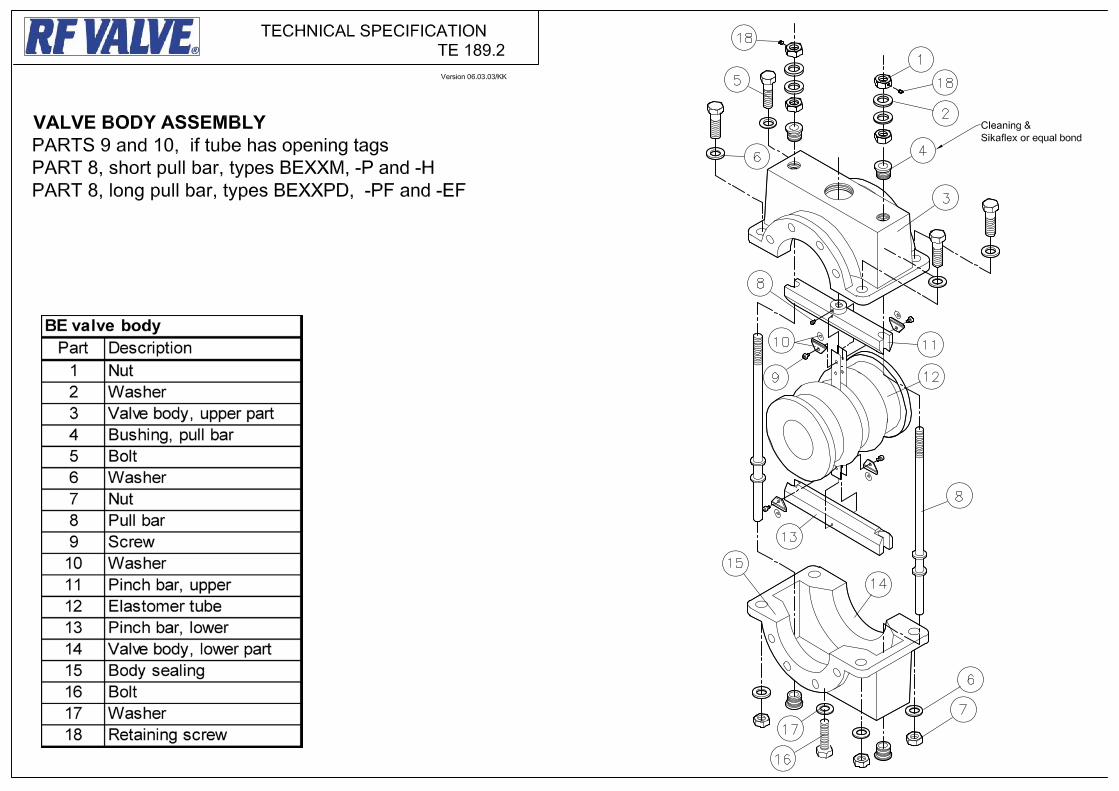
INSTALLATION, OPERATION AND MAINTENANCE MANUAL
TYPE (BE) ENCLOSED VALVE BODY Series 2001 SMART VALVE TM Wear Monitoring System
CUSTOMER SERVICE HOTLINE
Phone +1-410-850-4404 BE- 8/02 Rev. 6-01-2011 © 1993-2011 by RF Valves, Inc.
DOI: 9/15/09 Calibration Instructions for 1-5inch (25-125mm) RF Valve® with Manual Actuator Page 1
RF Valves, Inc. • 1342 Charwood Rd, Ste A • Hanover, MD 21076 • USA RF Valves, Oy • Tullitie 9 • 53500 Lappeenranta • FINLAND
Tel: +1 (410) 850-4404 • Fax: +1 (410) 850-4464 • Email: [email protected] Tel: +358-(0)20-785-1790 • Fax: +358-(0)20-785-1799 • Email: [email protected] WWW.RFVALVE.COM
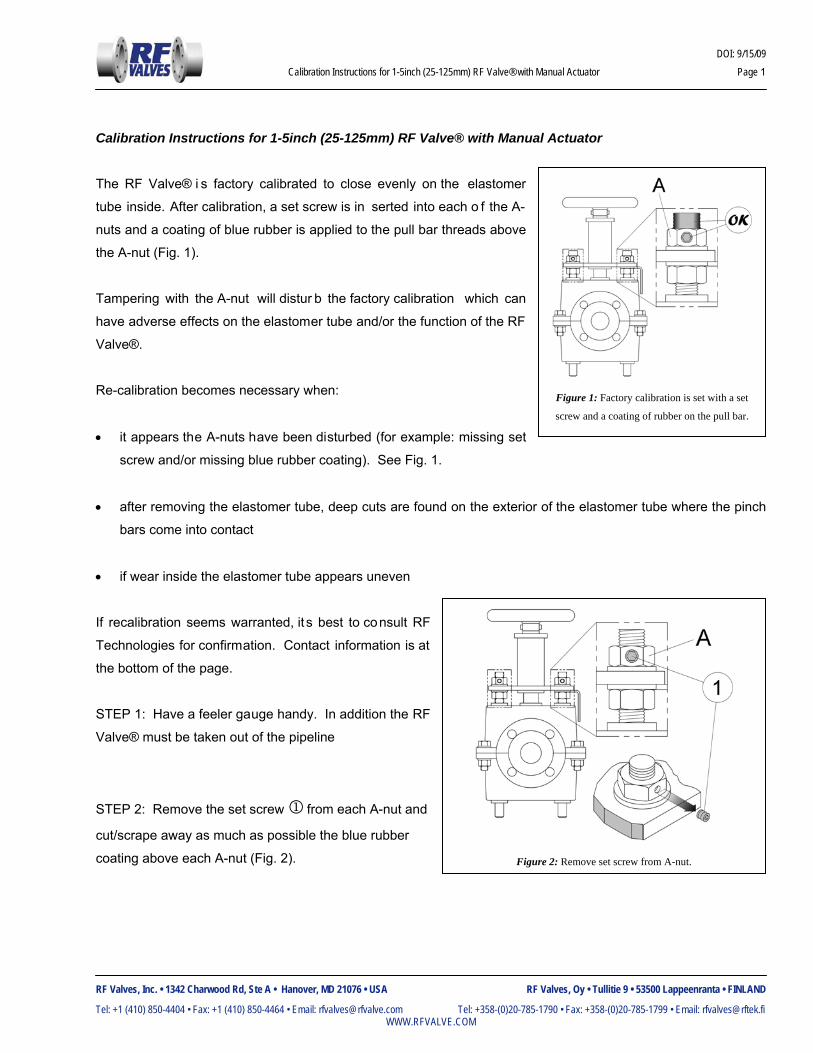
Calibration Instructions for 1-5inch (25-125mm) RF Valve® with Manual Actuator The RF Valve® i s factory calibrated to close evenly on the elastomer
tube inside. After calibration, a set screw is in serted into each o f the A-
nuts and a coating of blue rubber is applied to the pull bar threads above
the A-nut (Fig. 1).
Tampering with the A-nut will distur b the factory calibration which can
have adverse effects on the elastomer tube and/or the function of the RF
Valve®.
Re-calibration becomes necessary when:
• it appears the A-nuts have been disturbed (for example: missing set
screw and/or missing blue rubber coating). See Fig. 1.
• after removing the elastomer tube, deep cuts are found on the exterior of the elastomer tube where the pinch
bars come into contact
• if wear inside the elastomer tube appears uneven
If recalibration seems warranted, it s best to consult RF
Technologies for confirmation. Contact information is at
the bottom of the page.
STEP 1: Have a feeler gauge handy. In addition the RF
Valve® must be taken out of the pipeline
STEP 2: Remove the set screw 1 from each A-nut and
cut/scrape away as much as possible the blue rubber
coating above each A-nut (Fig. 2).
Figure 1: Factory calibration is set with a set
screw and a coating of rubber on the pull bar.
Figure 2: Remove set screw from A-nut.

DOI: 9/15/09 Calibration Instructions for 1-5inch (25-125mm) RF Valve® with Manual Actuator Page 2
RF Valves, Inc. • 1342 Charwood Rd, Ste A • Hanover, MD 21076 • USA RF Valves, Oy • Tullitie 9 • 53500 Lappeenranta • FINLAND
Tel: +1 (410) 850-4404 • Fax: +1 (410) 850-4464 • Email: [email protected] Tel: +358-(0)20-785-1790 • Fax: +358-(0)20-785-1799 • Email: [email protected] WWW.RFVALVE.COM
STEP 3: Now loosen ea ch A-nut until they come to a
distance X from the ends of their respective pull bar 2
(Fig. 3). The dista nce X is determined from the
information in Table 1.
STEP 4: Begin to actuat e the RF Val ve® closed and
observe the gap inside. Stop closing the RF Val ve®
when the gap is roughly 0.13” (3mm) in size (Fig 4).
Figure 3: Move A-nut to distance X
Figure 4: Actuate RF Valve closed until 0.13” (3mm) opening inside
Table 1: IMPERIAL UNITS
VALVE SIZE (in) DISTANCE X (in)
1 to 1-1/4 0.20
1.5 to 3 0.30
4 to 5 0.40
Table 1: METRIC UNITS
VALVE SIZE (mm) DISTANCE X (mm)
25 to 32 5
40 to 80 8
100 to 125 10

DOI: 9/15/09 Calibration Instructions for 1-5inch (25-125mm) RF Valve® with Manual Actuator Page 3
RF Valves, Inc. • 1342 Charwood Rd, Ste A • Hanover, MD 21076 • USA RF Valves, Oy • Tullitie 9 • 53500 Lappeenranta • FINLAND
Tel: +1 (410) 850-4404 • Fax: +1 (410) 850-4464 • Email: [email protected] Tel: +358-(0)20-785-1790 • Fax: +358-(0)20-785-1799 • Email: [email protected] WWW.RFVALVE.COM
The are two simple rules:
• to make the gap smaller on one side,
the A-nut should go DOWN (Fig. 6a)
• to make the gap bigger on one side,
the A-nut should go UP (Fig. 6b)
STEP 5: The next objective is to make sure the closure of
the RF Valve® remains even about the centerline.
Continue to actuate the RF Valve closed and ob serve the
opening inside. One or two gap s may be present (Fig. 5)
when the RF Valve is nearly closed.
NOTE: for the two g ap case, the gaps may be at the
extremes of the cl osure preventing them from being
observed directly. In this ca se the feeler gauge will have
to be used blindly.
STEP 6: FINE ADJUSTMENT FOR ONE GAP
If the RF Val ve® appears to have a si ngle
gap, be sure the gap is centere d within the
RF Valve®.
If the gap appears to be o ff-center (Figs. 6a
& 6b), adjustments will have to be done to
the A-nuts.
It may take a few iterations to get it right.
Figure 5: Observe the gap inside the RF Valve when nearly closed.
Figure 6: Fine Adjustment for One Gap
DOI: 9/15/09 Calibration Instructions for 1-5inch (25-125mm) RF Valve® with Manual Actuator Page 4
RF Valves, Inc. • 1342 Charwood Rd, Ste A • Hanover, MD 21076 • USA RF Valves, Oy • Tullitie 9 • 53500 Lappeenranta • FINLAND
Tel: +1 (410) 850-4404 • Fax: +1 (410) 850-4464 • Email: [email protected] Tel: +358-(0)20-785-1790 • Fax: +358-(0)20-785-1799 • Email: [email protected] WWW.RFVALVE.COM
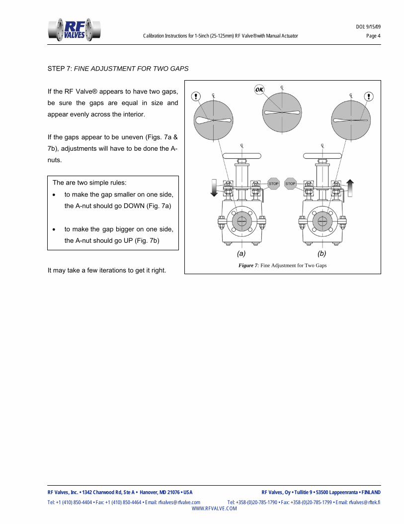
The are two simple rules:
• to make the gap smaller on one side,
the A-nut should go DOWN (Fig. 7a)
• to make the gap bigger on one side,
the A-nut should go UP (Fig. 7b)
STEP 7: FINE ADJUSTMENT FOR TWO GAPS
If the RF Valve® appears to have two gaps,
be sure the gaps are equal in size and
appear evenly across the interior.
If the gaps appear to be uneven (Figs. 7a &
7b), adjustments will have to be done the A-
nuts.
It may take a few iterations to get it right.
Figure 7: Fine Adjustment for Two Gaps

DOI: 9/15/09 Calibration Instructions for 1-5inch (25-125mm) RF Valve® with Manual Actuator Page 5
RF Valves, Inc. • 1342 Charwood Rd, Ste A • Hanover, MD 21076 • USA RF Valves, Oy • Tullitie 9 • 53500 Lappeenranta • FINLAND
Tel: +1 (410) 850-4404 • Fax: +1 (410) 850-4464 • Email: [email protected] Tel: +358-(0)20-785-1790 • Fax: +358-(0)20-785-1799 • Email: [email protected] WWW.RFVALVE.COM
STEP 8: Actuate the RF Valve® closed and insert a set screw into each of the A-nuts. If the hole in th e A-nut is
inaccessible, then it can be made accessible by doing the following:
• start with RF Valve® closed
• spin both B-nuts do wn at least
one turn (box 1 in Fig. 8).
• actuate the RF Valve® open (box
2 in Fig. 8).
• turn both the pull bar 2 and the
A-nut simultaneously as if they
were one part until the hole in the
A-nut is accessible (boxes 3 and 4
in Fig 8). IT IS VERY
IMPORTANT THAT THE A-NUT
DOES NOT MOVE/TURN
RELATIVE TO THE PULL BAR!
• actuate the RF Valve® closed and insert the set screw and tighten.
STEP 9: Tighten the B-nuts against the bottom of the fastening plate. DO NOT allow the A-nut to turn along the
pull bar during this step. Apply blue rubber coating (Fig. 1) to exposed thread above A-nut indicating RF Valve is
now correctly calibrated. DO NOT CHANGE!
STEP 10: Actuate the RF Valve® open and follow the instructions in section 3.0 INSTALLATION to put the RF
Valve® back in service.
Figure 8: Getting access to the set screw.

DOI: 5//15/09 Calibration Instructions RF Valve® with Manual Screw Jack Actuator Page 1
RF Valves, Inc. • 1342 Charwood Rd, Ste A • Hanover, MD 21076 • USA RF Valves, Oy • Tullitie 9 • 53500 Lappeenranta • FINLAND
Tel: +1 (410) 850-4404 • Fax: +1 (410) 850-4464 • Email: [email protected] Tel: +358-(0)20-785-1790 • Fax: +358-(0)20-785-1799 • Email: [email protected] WWW.RFVALVE.COM
Calibration Instructions for RF Valve® With Manual Screw Jack Actuator The following calibration instructions apply to RF Valves® with a manual
screw jack actuator (sometimes called a manual gear reduction actuator)
The RF Valve® is fa ctory calibrated to close with enough force to seal
against pipeline pressure. After calibration is completed, a set screw is
inserted into each of the A-nuts and a coating of blue rubber is applied to
the pull bar threads above the A-nut (Fig. 1).
Changing the A-nut setting will distur b the factory calibration which can
have adverse effects on the elastomer tube and/or the function of the RF
Valve®.
Re-calibration becomes necessary when:
• The A-nuts have been disturbed (for example: missing set screw and/or missing blue rubber coating). See
Fig. 1.
• After removing the elastomer tube for maintenance, deep cuts are found on the exterior of the elastomer tube
where the pinch bars come into contact
• If wear inside the elastomer tube appears uneven
If recalibration seems warranted, it’s best to consult RF Technologies for confirmation. Contact information is at
the bottom of the page.
Figure 1: Factory calibration is set with a set
screw and a coating of rubber on the pull bar.

DOI: 5//15/09 Calibration Instructions RF Valve® with Manual Screw Jack Actuator Page 2
RF Valves, Inc. • 1342 Charwood Rd, Ste A • Hanover, MD 21076 • USA RF Valves, Oy • Tullitie 9 • 53500 Lappeenranta • FINLAND
Tel: +1 (410) 850-4404 • Fax: +1 (410) 850-4464 • Email: [email protected] Tel: +358-(0)20-785-1790 • Fax: +358-(0)20-785-1799 • Email: [email protected] WWW.RFVALVE.COM
PREPARATION
STEP 1: Ha ve a feeler gauge handy. In additio n the RF
Valve® must be taken out of the pipeline. If possible, it is
recommended to put the RF Valve® up on wooden blocks
(Fig. 2)
STEP 2: Remove the set screw 1 from each A-nut and
cut/scrape away the blue rubber coating above each A-nut
(Fig. 3).
STEP 3: Now loosen each A-nut until they are flush to
the ends of their respective pull bar 2 (Fig. 4).
Figure 4: Turn A-nuts up.
Figure 3: Remove set screw from A-nut.
Figure 2: Set RF Valve® Atop Wood Blocks
DOI: 5//15/09 Calibration Instructions RF Valve® with Manual Screw Jack Actuator Page 3
RF Valves, Inc. • 1342 Charwood Rd, Ste A • Hanover, MD 21076 • USA RF Valves, Oy • Tullitie 9 • 53500 Lappeenranta • FINLAND
Tel: +1 (410) 850-4404 • Fax: +1 (410) 850-4464 • Email: [email protected] Tel: +358-(0)20-785-1790 • Fax: +358-(0)20-785-1799 • Email: [email protected] WWW.RFVALVE.COM
PRINCIPLES OF CALIBRATION
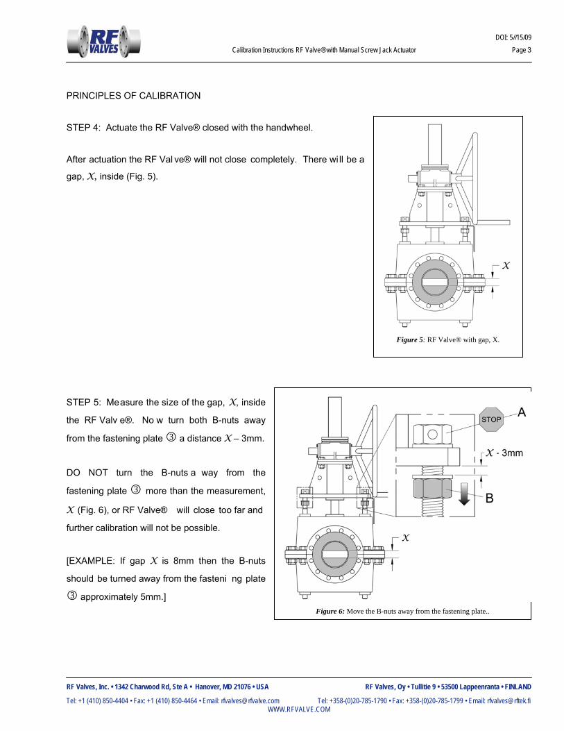
STEP 4: Actuate the RF Valve® closed with the handwheel.
After actuation the RF Val ve® will not close completely. There wi ll be a
gap, X, inside (Fig. 5).
STEP 5: Measure the size of the gap, X, inside
the RF Valv e®. No w turn both B-nuts away
from the fastening plate 3 a distance X – 3mm.
DO NOT turn the B-nuts a way from the
fastening plate 3 more than the measurement,
X (Fig. 6), or RF Valve® will close too far and
further calibration will not be possible.
[EXAMPLE: If gap X is 8mm then the B-nuts
should be turned away from the fasteni ng plate
3 approximately 5mm.]
Figure 5: RF Valve® with gap, X.
Figure 6: Move the B-nuts away from the fastening plate..

DOI: 5//15/09 Calibration Instructions RF Valve® with Manual Screw Jack Actuator Page 4
RF Valves, Inc. • 1342 Charwood Rd, Ste A • Hanover, MD 21076 • USA RF Valves, Oy • Tullitie 9 • 53500 Lappeenranta • FINLAND
Tel: +1 (410) 850-4404 • Fax: +1 (410) 850-4464 • Email: [email protected] Tel: +358-(0)20-785-1790 • Fax: +358-(0)20-785-1799 • Email: [email protected] WWW.RFVALVE.COM
STEP 6: Actuate the RF Valve® completely open until the handwheel stops turning and then turn the A -nuts
against the fastening plate 3 (Fig. 7). DO NOT allow the B-nuts to turn/move along the pull bar 2 during this
step!
STEP 7: Actuate the RF Valve® closed again and measure the size of the new gap, X1. It should be roughly
3mm in size (Fig. 8).
Figure 7: Turn the A-nuts against the fastening plate.
Figure 8: Measure the new gap, X1.

DOI: 5//15/09 Calibration Instructions RF Valve® with Manual Screw Jack Actuator Page 5
RF Valves, Inc. • 1342 Charwood Rd, Ste A • Hanover, MD 21076 • USA RF Valves, Oy • Tullitie 9 • 53500 Lappeenranta • FINLAND
Tel: +1 (410) 850-4404 • Fax: +1 (410) 850-4464 • Email: [email protected] Tel: +358-(0)20-785-1790 • Fax: +358-(0)20-785-1799 • Email: [email protected] WWW.RFVALVE.COM
The previous 7 steps demonstrated how the closure of the RF Valve® is adjusted just by changing the position of
the A-nuts along the pull bar. By moving the A-nuts down ward a distance, D, along the pull bar it will cause the
gap inside the RF Valve® to become smaller by D (Fig. 9b). On the other hand, to make the gap inside larger by
an amount U, the A-nuts should be repositioned upward a distance U (Fig. 10a & 10b).
CALIBRATION
STEP 8: The next obje ctive is to make the gap in side the RF Valve® 0.5mm AND the g ap should be evenly
distributed along the centerline of the RF Valve®.
NOTE: One or two gaps may be visible (Fig. 11). In the
case of two gap s, both gaps should end up a
measurement of 0.5mm. Having a light on opposite side
of the RF Valve® will help show the gap clearly.
NOTE: When two gaps are visible, the gaps may be at the
extreme edges of the closure preventing them from being
observed directly. In this case the feeler gau ge must be
inserted in e ach of the corners to me asure by “fe el” that
the 0.5mm gap s are p resent.
Figure 9: Move A-nuts down to make gap smaller. Figure 10: Move A-nuts up to make gap bigger.
Figure 11: Next objective: the 0.5mm gap(s).

DOI: 5//15/09 Calibration Instructions RF Valve® with Manual Screw Jack Actuator Page 6
RF Valves, Inc. • 1342 Charwood Rd, Ste A • Hanover, MD 21076 • USA RF Valves, Oy • Tullitie 9 • 53500 Lappeenranta • FINLAND
Tel: +1 (410) 850-4404 • Fax: +1 (410) 850-4464 • Email: [email protected] Tel: +358-(0)20-785-1790 • Fax: +358-(0)20-785-1799 • Email: [email protected] WWW.RFVALVE.COM
The are two simple rules:
• to make the gap smaller on one side,
the A-nut should go DOWN (Fig.
12a)
• to make the gap bigger on one side,
the A-nut should go UP (Fig. 12b)
The are two simple rules:
• to make the gap smaller on one side,
the A-nut should go DOWN (Fig.
13a)
• to make the gap bigger on one side,
the A-nut should go UP (Fig. 13b)
STEP 9: FINE ADJUSTMENT FOR ONE GAP
If the RF Val ve® appears to have a si ngle
gap, be sure the gap is centere d within the
RF Valve®.
If the gap a ppears to be off-center (Figs.
12a and 12b), adjustments will have to be
done to the A-nuts.
STEP 10: FINE ADJUSTMENT FOR TWO GAPS
If the RF Valve® appears to have two gaps,
be sure the gaps are equally 0.5mm in size
and appear evenly across the interior.
If the gaps a ppear to be uneven (Fig s. 13a
and 13b), adjustments will have to be done
the A-nuts.
Figure 12: Fine Adjustment for One Gap
Figure 13: Fine Adjustment for Two Gaps
DOI: 5//15/09 Calibration Instructions RF Valve® with Manual Screw Jack Actuator Page 7
RF Valves, Inc. • 1342 Charwood Rd, Ste A • Hanover, MD 21076 • USA RF Valves, Oy • Tullitie 9 • 53500 Lappeenranta • FINLAND
Tel: +1 (410) 850-4404 • Fax: +1 (410) 850-4464 • Email: [email protected] Tel: +358-(0)20-785-1790 • Fax: +358-(0)20-785-1799 • Email: [email protected] WWW.RFVALVE.COM
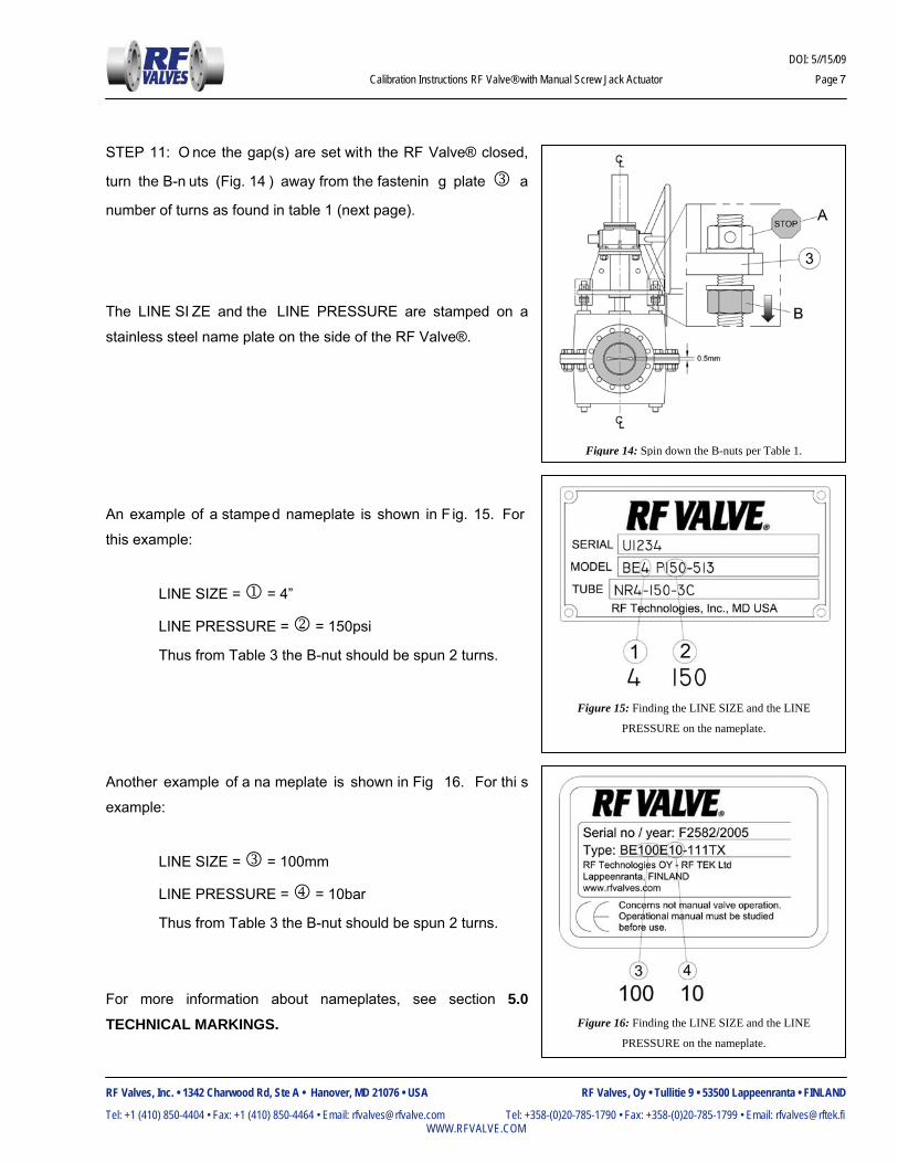
STEP 11: O nce the gap(s) are set with the RF Valve® closed,
turn the B-n uts (Fig. 14 ) away from the fastenin g plate 3 a
number of turns as found in table 1 (next page).
The LINE SI ZE and the LINE PRESSURE are stamped on a
stainless steel name plate on the side of the RF Valve®.
An example of a stamped nameplate is shown in F ig. 15. For
this example:
LINE SIZE = 1 = 4”
LINE PRESSURE = 2 = 150psi
Thus from Table 3 the B-nut should be spun 2 turns.
Another example of a na meplate is shown in Fig 16. For thi s
example:
LINE SIZE = 3 = 100mm
LINE PRESSURE = 4 = 10bar
Thus from Table 3 the B-nut should be spun 2 turns.
For more information about nameplates, see section 5.0 TECHNICAL MARKINGS.
Figure 14: Spin down the B-nuts per Table 1.
Figure 15: Finding the LINE SIZE and the LINE
PRESSURE on the nameplate.
Figure 16: Finding the LINE SIZE and the LINE
PRESSURE on the nameplate.

DOI: 5//15/09 Calibration Instructions RF Valve® with Manual Screw Jack Actuator Page 8
RF Valves, Inc. • 1342 Charwood Rd, Ste A • Hanover, MD 21076 • USA RF Valves, Oy • Tullitie 9 • 53500 Lappeenranta • FINLAND
Tel: +1 (410) 850-4404 • Fax: +1 (410) 850-4464 • Email: [email protected] Tel: +358-(0)20-785-1790 • Fax: +358-(0)20-785-1799 • Email: [email protected] WWW.RFVALVE.COM
STEP 12: A ctuate the RF Valve® o pen and tighten both A-
nuts against the fastening plate 3 (Fig. 18). DO NOT allow
the B-nut to turn along the pull bar 2 during this step.
TABLE 1: IMPERIAL UNITS
LINE SIZE (in) 1...1.25 1.5...3 4...6 8
10.. ..14 16...20 LINE PRESSURE (psi) 0…150 0...30 31...150 0...90 number of nut turns 2.75 2 1.75 1.5 1.25 1.75 1.75 TABLE 1: METRIC UNITS
LINE SIZE (mm) 25...32 40...80 100...150 200
250.. 350 400...500 LINE PRESSURE (bar) 0…10 0...2 3...10 0...6 number of nut turns 2.75 2 1.75 1.5 1.25 1.75 1.75
See Fig. 17 below for explanation of fractional nut turn
Figure 17: Fractional nut turn terminology.
Figure 18: Turn the A-nuts against the fastening plate.
DOI: 5//15/09 Calibration Instructions RF Valve® with Manual Screw Jack Actuator Page 9
RF Valves, Inc. • 1342 Charwood Rd, Ste A • Hanover, MD 21076 • USA RF Valves, Oy • Tullitie 9 • 53500 Lappeenranta • FINLAND
Tel: +1 (410) 850-4404 • Fax: +1 (410) 850-4464 • Email: [email protected] Tel: +358-(0)20-785-1790 • Fax: +358-(0)20-785-1799 • Email: [email protected] WWW.RFVALVE.COM
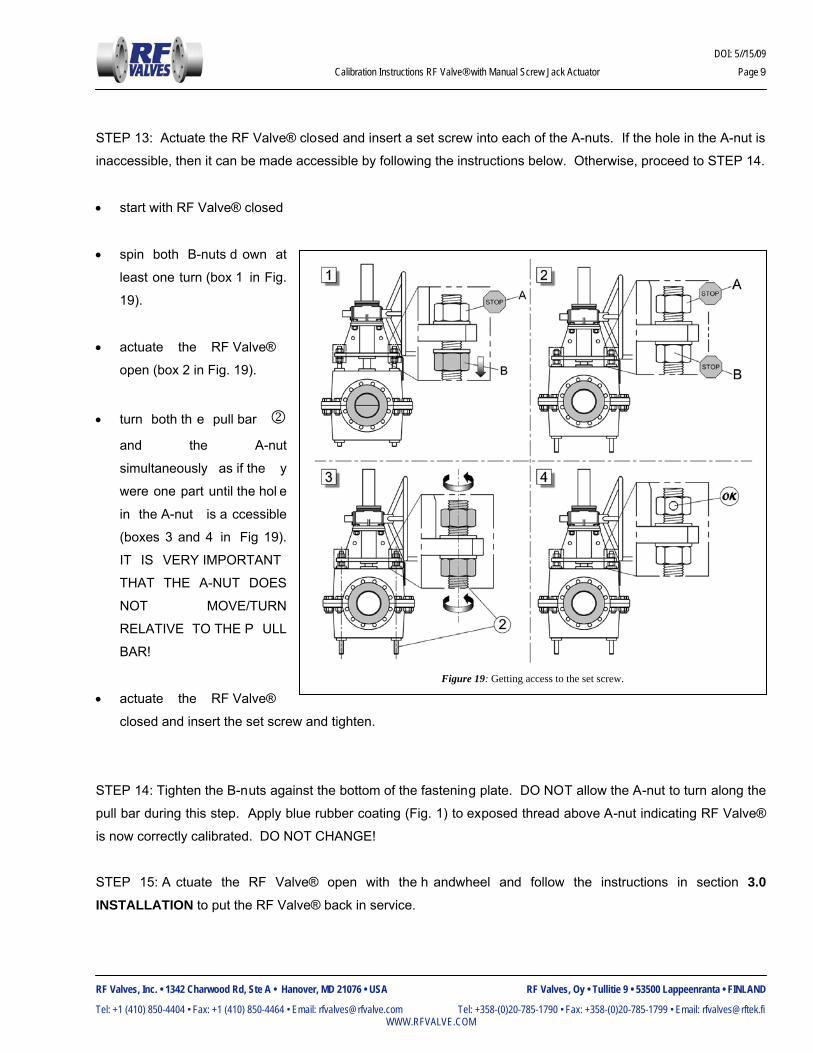
STEP 13: Actuate the RF Valve® closed and insert a set screw into each of the A-nuts. If the hole in the A-nut is
inaccessible, then it can be made accessible by following the instructions below. Otherwise, proceed to STEP 14.
• start with RF Valve® closed
• spin both B-nuts d own at
least one turn (box 1 in Fig.
19).
• actuate the RF Valve®
open (box 2 in Fig. 19).
• turn both th e pull bar 2 and the A-nut
simultaneously as if the y
were one part until the hol e
in the A-nut is a ccessible
(boxes 3 and 4 in Fig 19).
IT IS VERY IMPORTANT
THAT THE A-NUT DOES
NOT MOVE/TURN
RELATIVE TO THE P ULL
BAR!
• actuate the RF Valve®
closed and insert the set screw and tighten.
STEP 14: Tighten the B-nuts against the bottom of the fastening plate. DO NOT allow the A-nut to turn along the
pull bar during this step. Apply blue rubber coating (Fig. 1) to exposed thread above A-nut indicating RF Valve®
is now correctly calibrated. DO NOT CHANGE!
STEP 15: A ctuate the RF Valve® open with the h andwheel and follow the instructions in section 3.0 INSTALLATION to put the RF Valve® back in service.
Figure 19: Getting access to the set screw.
DOI: 1/28/09
RF Valve® Installation, Operation, and Maintenance Manual Page 14
RF Valves, Inc. • 1342 Charwood Rd, Ste A • Hanover, MD 21076 • USA RF Valves, Oy • Tullitie 9 • 53500 Lappeenranta • FINLAND
Tel: +1 (410) 850-4404 • Fax: +1 (410) 850-4464 • Email: [email protected] Tel: +358-(0)20-785-1790 • Fax: +358-(0)20-785-1799 • Email: [email protected] WWW.RFVALVE.COM
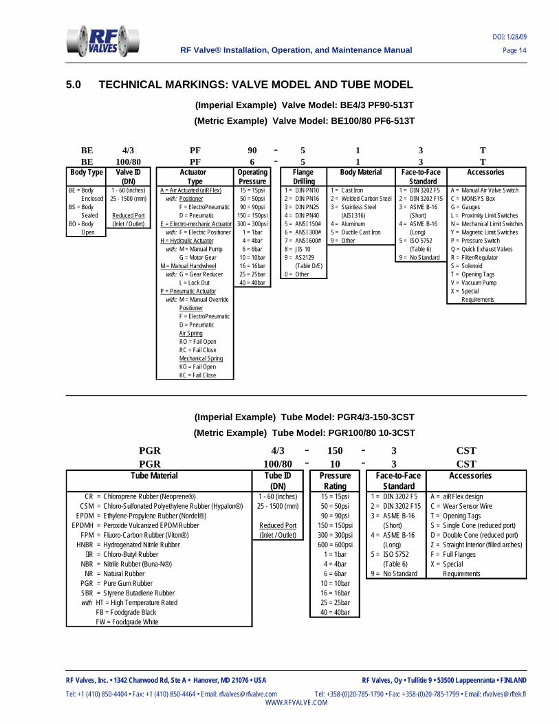
5.0 TECHNICAL MARKINGS: VALVE MODEL AND TUBE MODEL
(Imperial Example) Valve Model: BE4/3 PF90-513T (Metric Example) Valve Model: BE100/80 PF6-513T
BE 4/3 PF 90 - 5 1 3 TBE 100/80 PF 6 - 5 1 3 T
Body Type Valve ID Actuator Operating Flange Body Material Face-to-Face Accessories(DN) Type Pressure Drilling Standard
BE = Body 1 - 60 (inches) A = Air Actuated (aiRFlex) 15 = 15psi 1 = DIN PN10 1 = Cast Iron 1 = DIN 3202 F5 A = Manual Air Valve SwitchEnclosed 25 - 1500 (mm) with: Positioner 50 = 50psi 2 = DIN PN16 2 = Welded Carbon Steel 2 = DIN 3202 F15 C = MONSYS Box
BS = Body F = ElectroPneumatic 90 = 90psi 3 = DIN PN25 3 = Stainless Steel 3 = ASME B-16 G = GaugesSealed Reduced Port D = Pneumatic 150 = 150psi 4 = DIN PN40 (AISI 316) (Short) L = Proximity Limit Switches
BO =Body (Inlet / Outlet) E = Electro-mechanic Actuator 300 = 300psi 5 = ANSI 150# 4 = Aluminum 4 = ASME B-16 N = Mechanical Limit SwitchesOpen with: F = Electric Positioner 1 = 1bar 6 = ANSI 300# 5 = Ductile Cast Iron (Long) Y = Magnetic Limit Switches
H = Hydraulic Actuator 4 = 4bar 7 = ANSI 600# 9 = Other 5 = ISO 5752 P = Pressure Switchwith: M = Manual Pump 6 = 6bar 8 = JIS 10 (Table 6) Q = Quick Exhaust Valves
G = Motor Gear 10 = 10bar 9 = AS2129 9 = No Standard R = Filter/Regulator M = Manual Handwheel 16 = 16bar (Table D/E) S = Solenoid
with: G = Gear Reducer 25 = 25bar 0 = Other T = Opening TagsL = Lock Out 40 = 40bar V = Vacuum Pump
P = Pneumatic Actuator X = Specialwith: M = Manual Override Requirements
PositionerF = ElectroPneumaticD = PneumaticAir SpringRO = Fail OpenRC = Fail CloseMechanical SpringKO = Fail OpenKC = Fail Close
(Imperial Example) Tube Model: PGR4/3-150-3CST (Metric Example) Tube Model: PGR100/80 10-3CST
PGR 4/3 - 150 - 3 CST PGR 100/80 - 10 - 3 CST Tube Material Tube ID Pressure Face-to-Face Accessories
(DN) Rating Standard CR = Chloroprene Rubber (Neoprene®) 1 - 60 (inches) 15 = 15psi 1 = DIN 3202 F5 A = aiRFlex design
CSM = Chloro-Sulfonated Polyethylene Rubber (Hypalon®) 25 - 1500 (mm) 50 = 50psi 2 = DIN 3202 F15 C = Wear Sensor WireEPDM = Ethylene-Propylene Rubber (Nordel®) 90 = 90psi 3 = ASME B-16 T = Opening Tags
EPDMH = Peroxide Vulcanized EPDM Rubber Reduced Port 150 = 150psi (Short) S = Single Cone (reduced port)FPM = Fluoro-Carbon Rubber (Viton®) (Inlet / Outlet) 300 = 300psi 4 = ASME B-16 D = Double Cone (reduced port)
HNBR = Hydrogenated Nitrile Rubber 600 = 600psi (Long) Z = Straight Interior (filled arches)IIR = Chloro-Butyl Rubber 1 = 1bar 5 = ISO 5752 F = Full Flanges
NBR = Nitrile Rubber (Buna-N®) 4 = 4bar (Table 6) X = SpecialNR = Natural Rubber 6 = 6bar 9 = No Standard Requirements
PGR = Pure Gum Rubber 10 = 10barSBR = Styrene Butadiene Rubber 16 = 16barwith HT = High Temperature Rated 25 = 25bar
FB = Foodgrade Black 40 = 40barFW = Foodgrade White
HO 006.0 Update 2004-01-15/JR
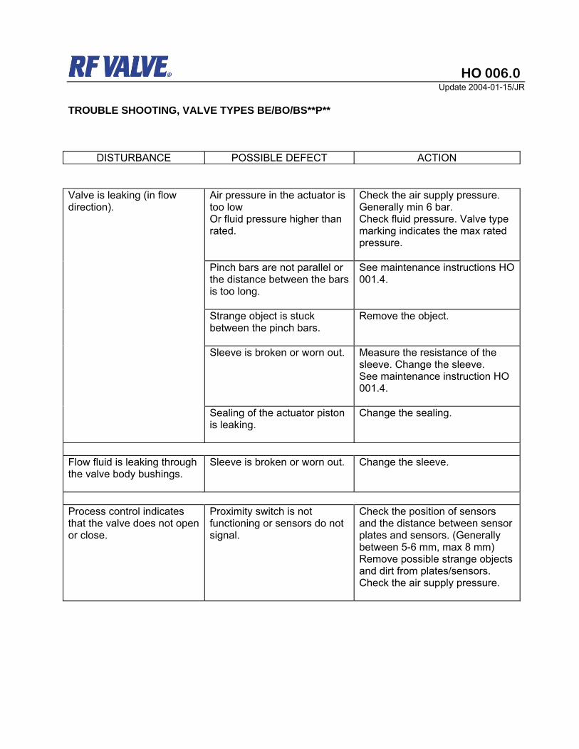
TROUBLE SHOOTING, VALVE TYPES BE/BO/BS**P**
DISTURBANCE POSSIBLE DEFECT ACTION
Valve is leaking (in flow direction).
Air pressure in the actuator is too low Or fluid pressure higher than rated.
Check the air supply pressure. Generally min 6 bar. Check fluid pressure. Valve type marking indicates the max rated pressure.
Pinch bars are not parallel or the distance between the bars is too long.
See maintenance instructions HO 001.4.
Strange object is stuck between the pinch bars.
Remove the object.
Sleeve is broken or worn out. Measure the resistance of the sleeve. Change the sleeve. See maintenance instruction HO 001.4.
Sealing of the actuator piston is leaking.
Change the sealing.
Flow fluid is leaking through the valve body bushings.
Sleeve is broken or worn out. Change the sleeve.
Process control indicates that the valve does not open or close.
Proximity switch is not functioning or sensors do not signal.
Check the position of sensors and the distance between sensor plates and sensors. (Generally between 5-6 mm, max 8 mm) Remove possible strange objects and dirt from plates/sensors. Check the air supply pressure.

SERVICE BULLETIN
HO 037.2 Page 1 / 2
Update 2009-02-24/JR
RF Valves, Inc. • 1342 Charwood Rd, Ste A • Hanover, MD 21076 • USA RF Valves, Oy • Tullitie 9 • 53500 Lappeenranta • FINLAND
Tel: +1 (410) 850-4404 • Fax: +1 (410) 850-4464 • Email: [email protected] Tel: +358-(0)20-785-1790 • Fax: +358-(0)20-785-1799 • Email: [email protected] WWW.RFVALVE.COM
TROUBLE SHOOTING, TUBE LIFE SHORT - VALVE TYPES BE/BO**P**and H** CHECK PROCESS CONDITIONS - Type of slurry, liquid, powder - Temperature min/medium/max ºC - Max operating pressure (barg) - Max pressure when valve is closed (barg) If the pipe/valve is washed - Type of washing liquid - Temperature max ºC - Max pressure (barg) - Time needed for washing CHECK VALVE OPERATING CONDITIONS - Valve type and serial no (machine plate) - Time in operation - Frequency of closing/opening, cycles/h etc - Supply air/hydraulic pressure min/max (barg)
- Valve closing/opening time - distance from the previous pipe bend, T-joint < 2*DN > 2*DN CHECK VALVE CONDITION - bolts and nuts tightened - pull bar locking nut fixed/sealed - air/hydraulic connections tight - actuator sealings are not leaking - Tmin -20ºC, - operation of the auxiliaries - position of the actuator Heavy actuators may need support if not vertical - describe the type of damage in the tube- take photos of the tube or/and sent to RF
POSSIBLE DEFECT ACTION Air /hydraulic pressure in the actuator is too low (also short periods) Or operating pressure higher than rated.
Valve type marking indicates the max rated pressure. - increase supply air pressure - larger actuator may be needed
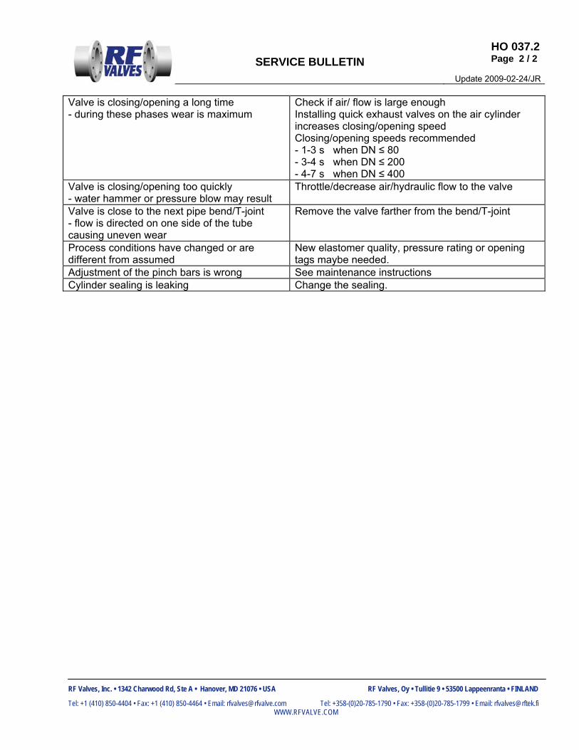
SERVICE BULLETIN
HO 037.2 Page 2 / 2
Update 2009-02-24/JR
RF Valves, Inc. • 1342 Charwood Rd, Ste A • Hanover, MD 21076 • USA RF Valves, Oy • Tullitie 9 • 53500 Lappeenranta • FINLAND
Tel: +1 (410) 850-4404 • Fax: +1 (410) 850-4464 • Email: [email protected] Tel: +358-(0)20-785-1790 • Fax: +358-(0)20-785-1799 • Email: [email protected] WWW.RFVALVE.COM
Valve is closing/opening a long time - during these phases wear is maximum
Check if air/ flow is large enough Installing quick exhaust valves on the air cylinder increases closing/opening speed Closing/opening speeds recommended - 1-3 s when DN ≤ 80 - 3-4 s when DN ≤ 200 - 4-7 s when DN ≤ 400
Valve is closing/opening too quickly - water hammer or pressure blow may result
Throttle/decrease air/hydraulic flow to the valve
Valve is close to the next pipe bend/T-joint - flow is directed on one side of the tube causing uneven wear
Remove the valve farther from the bend/T-joint
Process conditions have changed or are different from assumed
New elastomer quality, pressure rating or opening tags maybe needed.
Adjustment of the pinch bars is wrong See maintenance instructions Cylinder sealing is leaking Change the sealing.
RF Valves, Inc. • 1342-A Charwood Rd • Hanover, MD 21076, USA Tel.(410) 850-4404 • Fax (410) 850-4464 • www.rfvalve.com
1
APPENDICES
Bill of Materials
Dimensional “as built” drawings
Accessories

MATERIALS OF CONSTRUCTION
LINE DESCRIPTION MATERIAL1 GEAR REDUCER STEEL, CAST IRON, BONZE2 HEX BOLT AISI 3043 HANDW HEEL STEEL4 ACTUATOR BODY W ELDED STEEL5 LOCK W ASHER AISI 3046 HEX NUT AISI 3047 SET SCREW AISI 3048 FLAT W ASHER AISI 3049 HEX NUT AISI 304
10 SCREW AISI 30411 ON/OFF INDICATOR AISI 30412 EXTENSION BUSHING AISI 30413 PULL BAR BUSHING POLY ACETAL14 CENTER BUSHING POLY ACETAL15 HEX BOLT AISI 30416 FLAT W ASHER AISI 30417 UPPER VALVE BODY CAST IRON (6, 8)
W ELDED STEEL (10+)18 UPPER PINCH BAR STEEL19 SET SCREW AISI 30420 PULL BAR AISI 31621 ELASTOMER TUBE RUBBER22 LOW ER PINCH BAR STEEL23 LOW ER VALVE BODY CAST IRON (6, 8)
W ELDED STEEL (10+)