Embed Size (px)
Citation preview

SSAAFFEETTYY WWAARRNNIINNGGOnly qualified personnel should install and service the equipment. The installation, starting up, and servicing of heating, ventilating, and air-conditioningequipment can be hazardous and requires specific knowledge and training. Improperly installed, adjusted or altered equipment by an unqualified personcould result in death or serious injury. When working on the equipment, observe all precautions in the literature and on the tags, stickers, and labels thatare attached to the equipment.
April 2020 CCXXRRCC--SSVVXX0011JJ--EENN
Installation, Operation, and Maintenance
Air-Cooled Condenser20 to 60 Ton
CCCCRRCC – 20 to 60 TonsCCIIRRCC – 20 to 60 Tons

©2020 Trane CXRC-SVX01J-EN
IntroductionRead this manual thoroughly before operating orservicing this unit.
Warnings, Cautions, and NoticesSafety advisories appear throughout this manual asrequired. Your personal safety and the properoperation of this machine depend upon the strictobservance of these precautions.
The three types of advisories are defined as follows:
WARNINGIndicates a potentially hazardous situationwhich, if not avoided, could result in death orserious injury.
CAUTIONIndicates a potentially hazardous situationwhich, if not avoided, could result in minor ormoderate injury. It could also be used to alertagainst unsafe practices.
NOTICEIndicates a situation that could result inequipment or property-damage onlyaccidents.
Important Environmental ConcernsScientific research has shown that certain man-madechemicals can affect the earth’s naturally occurringstratospheric ozone layer when released to theatmosphere. In particular, several of the identifiedchemicals that may affect the ozone layer arerefrigerants that contain Chlorine, Fluorine and Carbon(CFCs) and those containing Hydrogen, Chlorine,Fluorine and Carbon (HCFCs). Not all refrigerantscontaining these compounds have the same potentialimpact to the environment. Trane advocates theresponsible handling of all refrigerants-includingindustry replacements for CFCs and HCFCs such assaturated or unsaturated HFCs and HCFCs.
Important Responsible RefrigerantPracticesTrane believes that responsible refrigerant practicesare important to the environment, our customers, andthe air conditioning industry. All technicians whohandle refrigerants must be certified according to localrules. For the USA, the Federal Clean Air Act (Section608) sets forth the requirements for handling,reclaiming, recovering and recycling of certainrefrigerants and the equipment that is used in theseservice procedures. In addition, some states ormunicipalities may have additional requirements thatmust also be adhered to for responsible managementof refrigerants. Know the applicable laws and followthem.
WWAARRNNIINNGGPPrrooppeerr FFiieelldd WWiirriinngg aanndd GGrroouunnddiinnggRReeqquuiirreedd!!FFaaiilluurree ttoo ffoollllooww ccooddee ccoouulldd rreessuulltt iinn ddeeaatthh oorrsseerriioouuss iinnjjuurryy..AAllll ffiieelldd wwiirriinngg MMUUSSTT bbee ppeerrffoorrmmeedd bbyy qquuaalliiffiieeddppeerrssoonnnneell.. IImmpprrooppeerrllyy iinnssttaalllleedd aanndd ggrroouunnddeeddffiieelldd wwiirriinngg ppoosseess FFIIRREE aanndd EELLEECCTTRROOCCUUTTIIOONNhhaazzaarrddss.. TToo aavvooiidd tthheessee hhaazzaarrddss,, yyoouu MMUUSSTT ffoolllloowwrreeqquuiirreemmeennttss ffoorr ffiieelldd wwiirriinngg iinnssttaallllaattiioonn aannddggrroouunnddiinngg aass ddeessccrriibbeedd iinn NNEECC aanndd yyoouurr llooccaall//ssttaattee//nnaattiioonnaall eelleeccttrriiccaall ccooddeess..
WWAARRNNIINNGGPPeerrssoonnaall PPrrootteeccttiivvee EEqquuiippmmeenntt ((PPPPEE))RReeqquuiirreedd!!FFaaiilluurree ttoo wweeaarr pprrooppeerr PPPPEE ffoorr tthhee jjoobb bbeeiinngguunnddeerrttaakkeenn ccoouulldd rreessuulltt iinn ddeeaatthh oorr sseerriioouuss iinnjjuurryy..TTeecchhnniicciiaannss,, iinn oorrddeerr ttoo pprrootteecctt tthheemmsseellvveess ffrroommppootteennttiiaall eelleeccttrriiccaall,, mmeecchhaanniiccaall,, aanndd cchheemmiiccaallhhaazzaarrddss,, MMUUSSTT ffoollllooww pprreeccaauuttiioonnss iinn tthhiiss mmaannuuaallaanndd oonn tthhee ttaaggss,, ssttiicckkeerrss,, aanndd llaabbeellss,, aass wweellll aass tthheeiinnssttrruuccttiioonnss bbeellooww::
•• BBeeffoorree iinnssttaalllliinngg//sseerrvviicciinngg tthhiiss uunniitt,,tteecchhnniicciiaannss MMUUSSTT ppuutt oonn aallll PPPPEE rreeqquuiirreedd ffoorrtthhee wwoorrkk bbeeiinngg uunnddeerrttaakkeenn ((EExxaammpplleess;; ccuuttrreessiissttaanntt gglloovveess//sslleeeevveess,, bbuuttyyll gglloovveess,, ssaaffeettyyggllaasssseess,, hhaarrdd hhaatt//bbuummpp ccaapp,, ffaallll pprrootteeccttiioonn,,eelleeccttrriiccaall PPPPEE aanndd aarrcc ffllaasshh ccllootthhiinngg))..AALLWWAAYYSS rreeffeerr ttoo aapppprroopprriiaattee SSaaffeettyy DDaattaaSShheeeettss ((SSDDSS)) aanndd OOSSHHAA gguuiiddeelliinneess ffoorrpprrooppeerr PPPPEE..
•• WWhheenn wwoorrkkiinngg wwiitthh oorr aarroouunndd hhaazzaarrddoouusscchheemmiiccaallss,, AALLWWAAYYSS rreeffeerr ttoo tthhee aapppprroopprriiaatteeSSDDSS aanndd OOSSHHAA//GGHHSS ((GGlloobbaall HHaarrmmoonniizzeeddSSyysstteemm ooff CCllaassssiiffiiccaattiioonn aanndd LLaabbeelllliinngg ooffCChheemmiiccaallss)) gguuiiddeelliinneess ffoorr iinnffoorrmmaattiioonn oonnaalllloowwaabbllee ppeerrssoonnaall eexxppoossuurree lleevveellss,, pprrooppeerrrreessppiirraattoorryy pprrootteeccttiioonn aanndd hhaannddlliinnggiinnssttrruuccttiioonnss..
•• IIff tthheerree iiss aa rriisskk ooff eenneerrggiizzeedd eelleeccttrriiccaallccoonnttaacctt,, aarrcc,, oorr ffllaasshh,, tteecchhnniicciiaannss MMUUSSTT ppuuttoonn aallll PPPPEE iinn aaccccoorrddaannccee wwiitthh OOSSHHAA,, NNFFPPAA7700EE,, oorr ootthheerr ccoouunnttrryy--ssppeecciiffiicc rreeqquuiirreemmeennttssffoorr aarrcc ffllaasshh pprrootteeccttiioonn,, PPRRIIOORR ttoo sseerrvviicciinnggtthhee uunniitt.. NNEEVVEERR PPEERRFFOORRMM AANNYY SSWWIITTCCHHIINNGG,,DDIISSCCOONNNNEECCTTIINNGG,, OORR VVOOLLTTAAGGEE TTEESSTTIINNGGWWIITTHHOOUUTT PPRROOPPEERR EELLEECCTTRRIICCAALL PPPPEE AANNDDAARRCC FFLLAASSHH CCLLOOTTHHIINNGG.. EENNSSUURREEEELLEECCTTRRIICCAALL MMEETTEERRSS AANNDD EEQQUUIIPPMMEENNTT AARREEPPRROOPPEERRLLYY RRAATTEEDD FFOORR IINNTTEENNDDEEDDVVOOLLTTAAGGEE..

CXRC-SVX01J-EN 3
WWAARRNNIINNGGFFoollllooww EEHHSS PPoolliicciieess!!FFaaiilluurree ttoo ffoollllooww iinnssttrruuccttiioonnss bbeellooww ccoouulldd rreessuulltt iinnddeeaatthh oorr sseerriioouuss iinnjjuurryy..
•• AAllll TTrraannee ppeerrssoonnnneell mmuusstt ffoollllooww tthheeccoommppaannyy’’ss EEnnvviirroonnmmeennttaall,, HHeeaalltthh aanndd SSaaffeettyy((EEHHSS)) ppoolliicciieess wwhheenn ppeerrffoorrmmiinngg wwoorrkk ssuucchh aasshhoott wwoorrkk,, eelleeccttrriiccaall,, ffaallll pprrootteeccttiioonn,, lloocckkoouutt//ttaaggoouutt,, rreeffrriiggeerraanntt hhaannddlliinngg,, eettcc.. WWhheerree llooccaallrreegguullaattiioonnss aarree mmoorree ssttrriinnggeenntt tthhaann tthheesseeppoolliicciieess,, tthhoossee rreegguullaattiioonnss ssuuppeerrsseeddee tthheesseeppoolliicciieess..
•• NNoonn--TTrraannee ppeerrssoonnnneell sshhoouulldd aallwwaayyss ffoolllloowwllooccaall rreegguullaattiioonnss..
NNOOTTIICCEEUUssee CCooppppeerr CCoonndduuccttoorrss OOnnllyy!!FFaaiilluurree ttoo uussee ccooppppeerr ccoonndduuccttoorrss ccoouulldd rreessuulltt iinneeqquuiippmmeenntt ddaammaaggee aass tthhee eeqquuiippmmeenntt wwaass nnoottddeessiiggnneedd oorr qquuaalliiffiieedd ttoo aacccceepptt ootthheerr ttyyppeess ooffccoonndduuccttoorrss..
WWAARRNNIINNGGHHaazzaarrddoouuss VVoollttaaggee ww//CCaappaacciittoorrss!!FFaaiilluurree ttoo ddiissccoonnnneecctt ppoowweerr aanndd ddiisscchhaarrggeeccaappaacciittoorrss bbeeffoorree sseerrvviicciinngg ccoouulldd rreessuulltt iinn ddeeaatthh oorrsseerriioouuss iinnjjuurryy..DDiissccoonnnneecctt aallll eelleeccttrriicc ppoowweerr,, iinncclluuddiinngg rreemmootteeddiissccoonnnneeccttss aanndd ddiisscchhaarrggee aallll mmoottoorr ssttaarrtt//rruunnccaappaacciittoorrss bbeeffoorree sseerrvviicciinngg.. FFoollllooww pprrooppeerrlloocckkoouutt//ttaaggoouutt pprroocceedduurreess ttoo eennssuurree tthhee ppoowweerrccaannnnoott bbee iinnaaddvveerrtteennttllyy eenneerrggiizzeedd.. FFoorr vvaarriiaabblleeffrreeqquueennccyy ddrriivveess oorr ootthheerr eenneerrggyy ssttoorriinnggccoommppoonneennttss pprroovviiddeedd bbyy TTrraannee oorr ootthheerrss,, rreeffeerr ttootthhee aapppprroopprriiaattee mmaannuuffaaccttuurreerr’’ss lliitteerraattuurree ffoorraalllloowwaabbllee wwaaiittiinngg ppeerriiooddss ffoorr ddiisscchhaarrggee ooffccaappaacciittoorrss.. VVeerriiffyy wwiitthh aa CCAATT IIIIII oorr IIVV vvoollttmmeetteerrrraatteedd ppeerr NNFFPPAA 7700EE tthhaatt aallll ccaappaacciittoorrss hhaavveeddiisscchhaarrggeedd..FFoorr aaddddiittiioonnaall iinnffoorrmmaattiioonn rreeggaarrddiinngg tthhee ssaaffeeddiisscchhaarrggee ooff ccaappaacciittoorrss,, sseeee PPRROODD--SSVVBB0066**--EENN..
CopyrightThis document and the information in it are theproperty of Trane, and may not be used or reproducedin whole or in part without written permission. Tranereserves the right to revise this publication at any time,and to make changes to its content without obligationto notify any person of such revision or change.
TrademarksAll trademarks referenced in this document are thetrademarks of their respective owners.
Revision HistoryRunning changes are included in this version andrefrigerant charge data has been removed. Pleasecontact Product Support for specific chargeinformation.
IInnttrroodduuccttiioonn
4 CXRC-SVX01J-EN
Overview . . . . . . . . . . . . . . . . . . . . . . . . . . . . . . . . . . . 5About This Manual . . . . . . . . . . . . . . . . . . . . . . . 5
Related Publications . . . . . . . . . . . . . . . . . . . . . . 5
Commercial Self-Contained Air-CooledCondenser. . . . . . . . . . . . . . . . . . . . . . . . . . . . . . . . . . 6
General Data . . . . . . . . . . . . . . . . . . . . . . . . . . . . . . . 7Unit Description . . . . . . . . . . . . . . . . . . . . . . . . . . 7
Unit Nameplate . . . . . . . . . . . . . . . . . . . . . . . . . . 7
Pre-Installation . . . . . . . . . . . . . . . . . . . . . . . . . . . . . 8Receiving Shipment . . . . . . . . . . . . . . . . . . . . . . 8
Contractor InstallationResponsibilities . . . . . . . . . . . . . . . . . . . . . . . . . . 8
Dimensions and Weights . . . . . . . . . . . . . . . . . . . 9Service Clearances . . . . . . . . . . . . . . . . . . . . . . 11
Installation - Mechanical. . . . . . . . . . . . . . . . . . . 13Unit Handling Procedure . . . . . . . . . . . . . . . . . 13
Installation Preparation . . . . . . . . . . . . . . . . . . 14
Unit Isolation. . . . . . . . . . . . . . . . . . . . . . . . . . . . 14Spring Isolators . . . . . . . . . . . . . . . . . . . . . . 14Leveling the Unit. . . . . . . . . . . . . . . . . . . . . 16
Refrigerant Piping . . . . . . . . . . . . . . . . . . . . . . . 16General RefrigerantRecommendations . . . . . . . . . . . . . . . . . . . 16Interconnecting Piping . . . . . . . . . . . . . . . 17
Installation — Electrical. . . . . . . . . . . . . . . . . . . . 19General ElectricalRecommendations. . . . . . . . . . . . . . . . . . . . . . . 19
Power Supply Wiring . . . . . . . . . . . . . . . . . . . . 19
System Interconnection Wiring . . . . . . . . . . . 19
Unit Wiring Diagrams . . . . . . . . . . . . . . . . . . . . 19
Unit Voltage. . . . . . . . . . . . . . . . . . . . . . . . . . . . . 19
Voltage Supply . . . . . . . . . . . . . . . . . . . . . . . . . . 19
Voltage Imbalance . . . . . . . . . . . . . . . . . . . . . . . 20
Operating Principles . . . . . . . . . . . . . . . . . . . . . . . 21Control Sequences of Operation forUnits with IntelliPak. . . . . . . . . . . . . . . . . . . . . . 21
Typical Unit Operation . . . . . . . . . . . . . . . 21Low Ambient DamperOperation . . . . . . . . . . . . . . . . . . . . . . . . . . . 21Condenser Fan Operation. . . . . . . . . . . . . 22
Pre-Start Checklist . . . . . . . . . . . . . . . . . . . . . . . . . 23
Startup and Shutdown . . . . . . . . . . . . . . . . . . . . 24Startup . . . . . . . . . . . . . . . . . . . . . . . . . . . . . . . . . 24
Normal Unit Shut Down. . . . . . . . . . . . . . . . . . 24
Seasonal Shut Down. . . . . . . . . . . . . . . . . . . . . 24
Seasonal Startup . . . . . . . . . . . . . . . . . . . . . . . . 24
Maintenance . . . . . . . . . . . . . . . . . . . . . . . . . . . . . . 25Refrigerant System . . . . . . . . . . . . . . . . . . . . . . 25
Refrigerant Leak Test Procedure. . . . . . . 25System Evacuation Procedures . . . . . . . 26Refrigerant Charging . . . . . . . . . . . . . . . . . 28
Maintenance Periodic Procedures . . . . . . . . . 28Periodic Maintenance Checklist . . . . . . . 28Annual Maintenance Checklist . . . . . . . . 29Cleaning the Coil. . . . . . . . . . . . . . . . . . . . . 29Low Ambient DamperAdjustment. . . . . . . . . . . . . . . . . . . . . . . . . . 29
Troubleshooting. . . . . . . . . . . . . . . . . . . . . . . . . 30
Wiring Diagrams . . . . . . . . . . . . . . . . . . . . . . . . . . 31
Table of Contents
CXRC-SVX01J-EN 5
OverviewAbout This ManualNNoottee:: One copy of this document ships inside the
control panel of each unit and is customerproperty. It must be retained by maintenancepersonnel.
This manual describes proper installation, operation,and maintenance procedures for air cooled systems. Bycarefully reviewing the information within this manualand following the instructions, risk of improperoperation and/or component damage will beminimized. It is important that periodic maintenance beperformed to help assure trouble free operation. Amaintenance schedule is provided at the end of thismanual. Should equipment failure occur, contact aqualified service organization with qualified,
experienced HVAC technicians to properly diagnoseand repair this equipment.
Related Publications• IntelliPak® Self-Contained Programming Guide,
PKG-SVP01
• Commercial Self-Contained IntelliPak SignatureSeries Installation, Owner, and Diagnostic Manual,SCXF-SVX01
• Commercial Self-Contained IntelliPak ModularSeries Installation, Owner, and Diagnostic Manual,SCXG-SVX01
• The Trane Air Conditioning Manual

6 CXRC-SVX01J-EN
Commercial Self-Contained Air-Cooled Condenser
Digit 1 — Unit Model
C = Condenser
Digit 2 — Unit Type
C = CommercialI = Industrial
Digit 3 — Condenser Medium
R = Remote
Digit 4 — Development Sequence
C = C
Digit 5, 6, 7 — Nominal Capacity
020 = 20 Tons029 = 29 Tons032 = 32 Tons035 = 35 Tons040 = 40 Tons050 = 50 Tons060 = 60 Tons
Digit 8 — Unit Voltage
4 = 460 Volt/60 Hz/3 ph5 = 575 Volt/60 Hz/3 ph6 = 200 Volt/60 Hz/3 ph
Digit 9 — Control Option
0 = No Low Ambient, IPakA = No Low Ambient, T-Stat*B = Low Ambient, IPakC = Low Ambient, T-Stat*
Note: *T-Stat only available on SCRG.
Digit 10, 11—Design Sequence
** = Factory Assigned
Digit 12— Unit Finish
1 = Paint — Slate Gray
Digit 13— Coil Options
A = Non-Coated AluminumC = Protective Coating Aluminum
Digit 14— Unit Isolators
0 = NoneA = Spring IsolatorsB = Isopads
Digit 15— Panels
1 = Louvered Panels
Digit 16— Agency
0 = NoneU =With UL Listing
CXRC-SVX01J-EN 7
General DataUnit DescriptionModel CCRC/CIRC units function as the outdoorcondenser unit for appropriately sized splitrefrigeration systems. These units operate inconjunction with a matched indoor compressor/evaporator configuration (Trane models SCRF, SIRF,SCRG, or SIRG) and provide refrigerant condensing forthese systems down to a normal ambient temperatureof 45° Fahrenheit. Operation to 0°F ambient is possiblewith the addition of the optional external mount lowambient dampers. Refer to the section, “Low AmbientDamper Adjustment,” p. 29.
NNoottee:: Refer to the appropriate Indoor Unit (SCRG orSCRF) Installation, Operation, and Maintenancemanual for refrigerant charge.
The factory provided unit-mounted control panelcontains all required fan cycling controls, compressorinterlocks and 115 V control power transformer. Eachunit features two independent refrigerant circuits withan integral sub-cooling loop. The slab condenser coilsare aluminum fins bonded to copper tubing. Louveredcondenser grills are for coil protection and available asan option to order. Direct drive, vertical discharge fansare provided with built-in current and overloadprotection. Head pressure control dampers areavailable if low ambient operation is required.
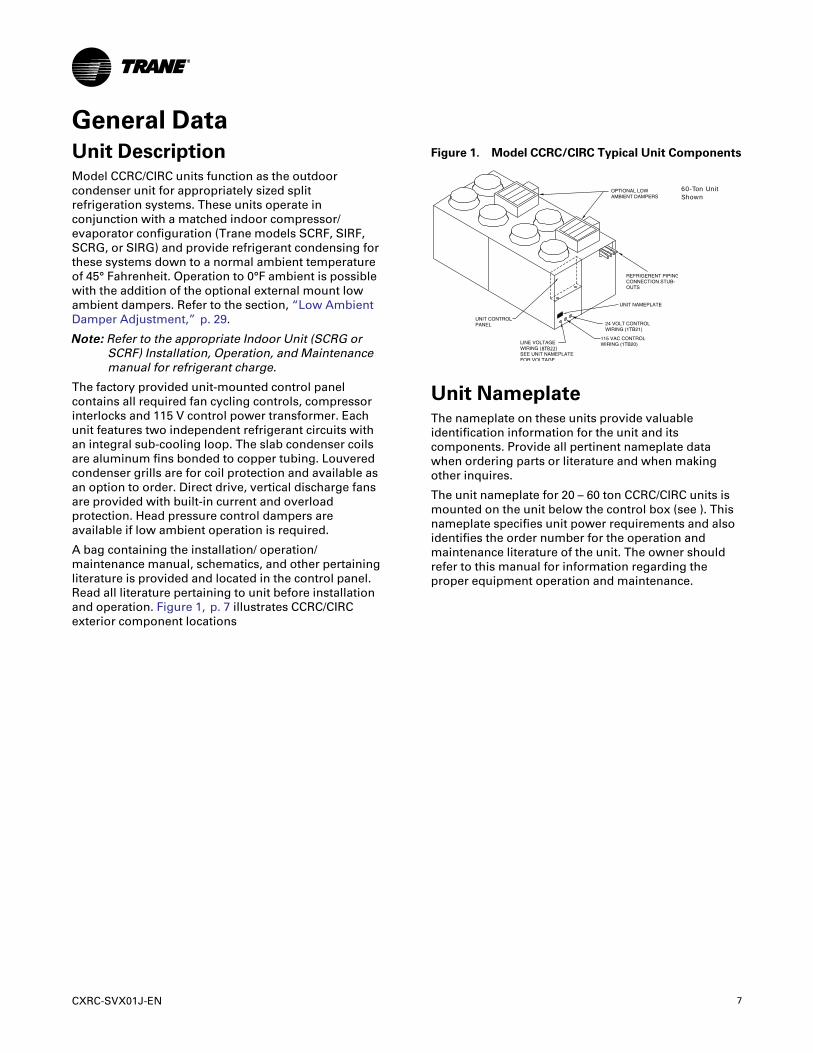
A bag containing the installation/ operation/maintenance manual, schematics, and other pertainingliterature is provided and located in the control panel.Read all literature pertaining to unit before installationand operation. Figure 1, p. 7 illustrates CCRC/CIRCexterior component locations
Figure 1. Model CCRC/CIRC Typical Unit Components
8TB22
60-Ton Unit Shown
Unit NameplateThe nameplate on these units provide valuableidentification information for the unit and itscomponents. Provide all pertinent nameplate datawhen ordering parts or literature and when makingother inquires.
The unit nameplate for 20 – 60 ton CCRC/CIRC units ismounted on the unit below the control box (see ). Thisnameplate specifies unit power requirements and alsoidentifies the order number for the operation andmaintenance literature of the unit. The owner shouldrefer to this manual for information regarding theproper equipment operation and maintenance.

8 CXRC-SVX01J-EN
Pre-InstallationReceiving ShipmentUpon receiving shipment, complete the followingchecklist:
☐ Inspect individual cartons before accepting. Checkfor rattles, bent carton corners, or other visibleindications of shipping damage.
☐ If a unit appears damaged, inspect it immediatelybefore accepting the shipment. Make specificnotations concerning the damage on the freight bill.Do not refuse delivery.
☐ Inspect the unit for concealed damage before it isstored and as soon as possible after delivery.Report concealed damage to the freight line withinthe allotted time after delivery. Check with thecarrier for their allotted time to submit a claim.
☐ Do not move damaged material from the receivinglocation. It is the receiver’s responsibility to providereasonable evidence that concealed damage didnot occur after delivery.
☐ Do not continue unpacking the shipment if itappears damaged. Retain all internal packing,cartons, and crate. Take photos of damagedmaterial if possible.
☐ Notify the carrier’s terminal of the damageimmediately by phone and mail. Request animmediate joint inspection of the damage by thecarrier and consignee.
☐ Notify your Trane representative of the damage andarrange for repair. Have the carrier inspect thedamage before making any repairs to the unit.
Contractor InstallationResponsibilitiesComplete the following checklist before beginning finalunit installation.
☐ Verify the unit size and tagging with the unitnameplate.
☐ Ensure that the floor or foundation is level, solid,and sufficient to support the unit and accessoryweights. Level or repair the floor before positioningthe unit if necessary.
NNoottee:: For a detailed discussion of base andfoundation construction see the Trane AirConditioning Manual. This manual isavailable through the local Trane sales office.
NNoottee:: On rooftop applications be certain that theroof structure has sufficient strength tosupport the unit operating weight. See Table1, p. 9 or unit shipping weight and operatingweight, and Table 3, p. 15 for point loadinginformation.
☐ Allow minimum recommended clearances forroutine maintenance and service. Allow space atend of the unit for shaft removal and servicing.Refer to unit submittal for dimensions. Refer to thesection, .
☐ Allow three (3) fan diameters above the unit for thedischarge ductwork. Return air enters the rear ofthe unit and conditioned supply air dischargesthrough the top.
☐ Electrical connection knockouts are on the top, leftside of the unit.
☐ Allow adequate space for piping access and panelremoval. Condenser water piping, refrigerantpiping, and condensate drain connections are onthe lower left end panel.
NNoottee:: Unit height and connection locations willchange if using vibration isolators. The unitheight may increase up to 5 7/8” with spring-type isolators.
☐ Electrical supply power must meet specific balanceand voltage requirements as described in thesection, “Installation — Electrical,” p. 19.
☐ FFoorr aaiirr--ccoooolleedd uunniittss oonnllyy:: The installer isresponsible for providing and installing the remoteair-cooled condenser and refrigerant piping,including filter driers.

CXRC-SVX01J-EN 9
Dimensions and WeightsFigure 2. CCRC/CIRC 20, 29, and 32 Ton
(Optional) LowAmbient Damper(One damper percircuit)
Refrigerant LineConnections
Frontal View
ACAB
AA
Figure 3. CCRC/CIRC 35 and 40 Ton
(Optional) LowAmbient Damper (One Damper per Circuit)
Refrigerant LineConnections
Frontal View
ACAB
AA
Figure 4. CCRC/CIRC 50 and 60 Ton(Optional) LowAmbient Damper (One Damper per Circuit)
Refrigerant LineConnections
Frontal View
ACAB
AA
Table 1. CCRC/CIRC Unit Weights
Unit Size ShippingWeight lbs (kg). OperatingWeight lbs.(kg)
CCRC/CIRC 20 2030 (920) 1906 (865)
CCRC/CIRC 29 2084 (945) 1960 (890)
CCRC/CIRC 32 2138 (970) 2014 (915)
CCRC/CIRC 35 3018 (1370) 2833 (1285)
CCRC/CIRC 40 3072 (1395) 2887 (1310)
CCRC/CIRC 50 3995 (1810) 3695 (1675)
CCRC/CIRC 60 4275 (1940) 3975 (1805)
Table 2. CCRC/CIRC Unit Dimensions
Unit Tons AA AB AC
CCRC/CIRC20, 29, 3270-1/8 7' - 4 7' - 4
(1781) (2235) (2235)
CCRC/CIRC35, 4070-1/8 10' - 10 3/4 7' - 4
(1781) (3321) (2235)
CCRC/CIRC50, 6070-1/8 14' - 8 7' - 4
(1781) (4470) (2235)
10 CXRC-SVX01J-EN
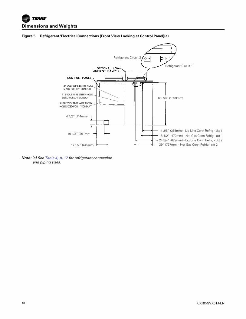
Figure 5. Refrigerant/Electrical Connections (Front View Looking at Control Panel)(a)
10 1/2” (261mm)B)
)
2)
REFRIGERANT CIRCUIT 2
REFRIGERANT CIRCUIT 1
24 VOLT WIRE ENTRY HOLESIZED FOR 3/4” CONDUIT
115 VOLT WIRE ENTRY HOLESIZED FOR 3/4” CONDUIT
SUPPLY VOLTAGE WIRE ENTRY HOLE SIZED FOR 1” CONDUIT
66 7/8” (1699mm)
18 1
4 1/2” (114mm)
1/2” (470mm) - Hot Gas Conn Refrig - ckt
17 1/2” (445mm)
14 3/8” (365mm) - Liq Line Conn Refrig - ckt 1
24 3/4” (629mm) - Liq Line Conn Refrig - ckt 2
Refrigerant Circuit 1
29” (737mm) - Hot Gas Conn Refrig - ckt 2
Refrigerant Circuit 2
NNoottee:: (a) See Table 4, p. 17 for refrigerant connectionand piping sizes.
DDiimmeennssiioonnss aanndd WWeeiigghhttss

CXRC-SVX01J-EN 11
Service ClearancesProvide sufficient clearance around the unit to allowunrestricted access to control panel, condenser coils,refrigerant connections and any other service points.Refer to Figure 2, p. 9 through Figure 4, p. 9 for unitdimensions and through Figure 7, p. 11 forrecommended clearances for each specific unit. Theseclearances allow for proper unit operation, airflow, andservice access.
NNoottee:: To prevent unit capacity reduction, providerecommended operating clearances.
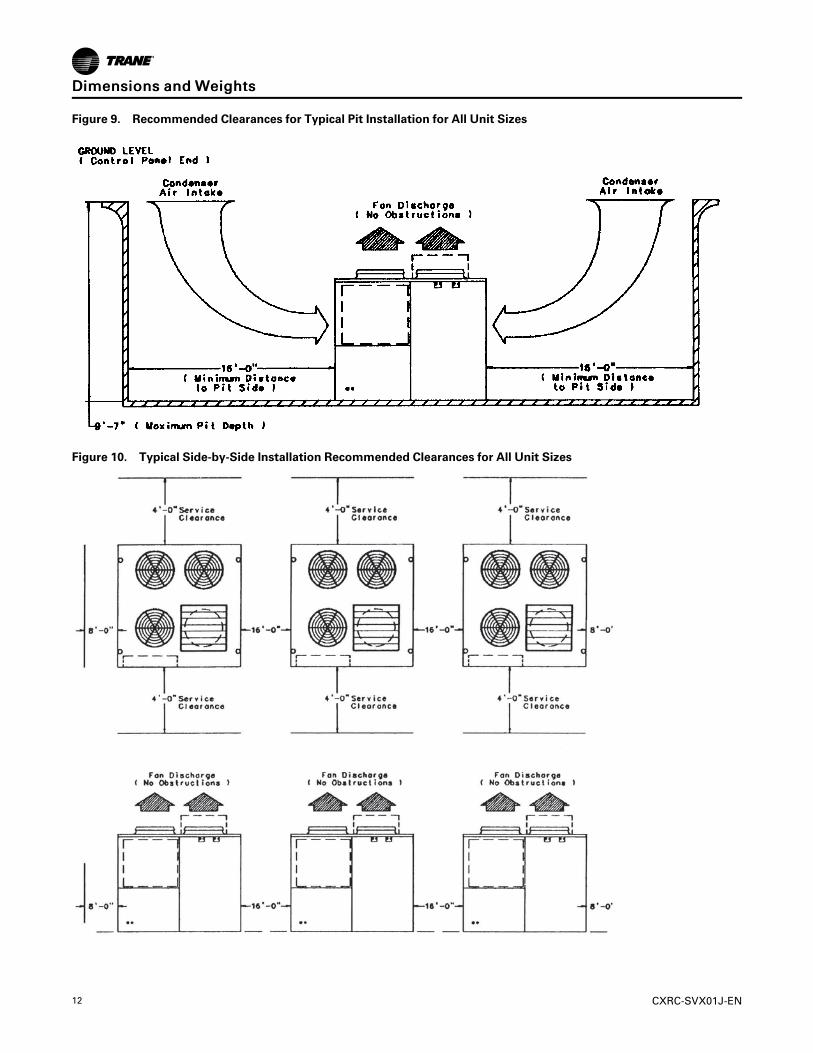
If unit is installed in a pit, the depth of the pit must notexceed 1.5 times the unit height and airflow clearancesare doubled. See for specific pit installation clearanceinstructions.
If multiple units are placed side-by-side, the minimumdistance between units must be twice the normalrecommended side clearances (8’ X 2’ = 16’ betweenunits). See Figure 10, p. 12 for specific side-by-sideinstallation clearance instructions.
Do not install unit under an overhang. Obstructing thefan discharge in this manner can cause recirculation ofthe warm discharge air and result in coil starvation.
Figure 6. Top View CCRC/CIRC 35, 40 Ton
96” (2132 mm)
48” (1066 mm)
96” (2132 mm)
48” (1066 mm)
Control Panel
C B
D A
F
E
Figure 7. Top View CCRC/CIRC 50, 60 Ton
96” (2132 mm)
48” (1066 mm)
96” (2132 mm)
48” (1066 mm)
Control Panel
C B
D A
F
E
G
H
Figure 8. Typical pit Installation Recommended Clearances
DDiimmeennssiioonnss aanndd WWeeiigghhttss
12 CXRC-SVX01J-EN
Figure 9. Recommended Clearances for Typical Pit Installation for All Unit Sizes
Figure 10. Typical Side-by-Side Installation Recommended Clearances for All Unit Sizes
DDiimmeennssiioonnss aanndd WWeeiigghhttss
CXRC-SVX01J-EN 13
Installation - MechanicalUnit Handling Procedure
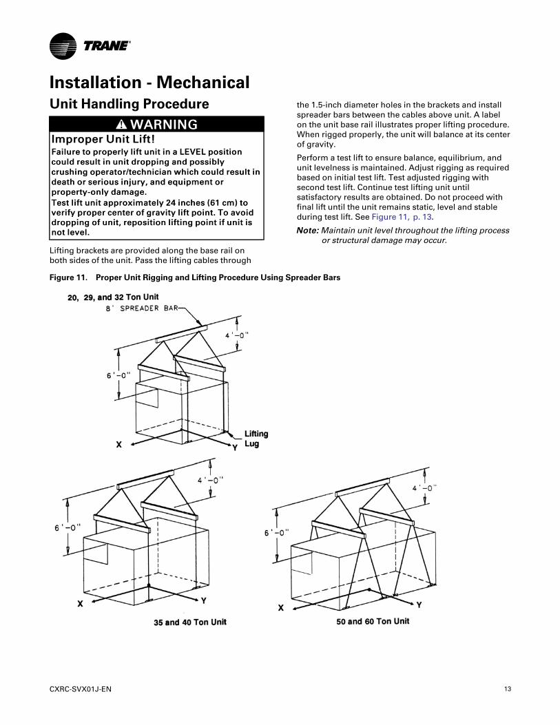
WWAARRNNIINNGGIImmpprrooppeerr UUnniitt LLiifftt!!FFaaiilluurree ttoo pprrooppeerrllyy lliifftt uunniitt iinn aa LLEEVVEELL ppoossiittiioonnccoouulldd rreessuulltt iinn uunniitt ddrrooppppiinngg aanndd ppoossssiibbllyyccrruusshhiinngg ooppeerraattoorr//tteecchhnniicciiaann wwhhiicchh ccoouulldd rreessuulltt iinnddeeaatthh oorr sseerriioouuss iinnjjuurryy,, aanndd eeqquuiippmmeenntt oorrpprrooppeerrttyy--oonnllyy ddaammaaggee..TTeesstt lliifftt uunniitt aapppprrooxxiimmaatteellyy 2244 iinncchheess ((6611 ccmm)) ttoovveerriiffyy pprrooppeerr cceenntteerr ooff ggrraavviittyy lliifftt ppooiinntt.. TToo aavvooiiddddrrooppppiinngg ooff uunniitt,, rreeppoossiittiioonn lliiffttiinngg ppooiinntt iiff uunniitt iissnnoott lleevveell..
Lifting brackets are provided along the base rail onboth sides of the unit. Pass the lifting cables through
the 1.5-inch diameter holes in the brackets and installspreader bars between the cables above unit. A labelon the unit base rail illustrates proper lifting procedure.When rigged properly, the unit will balance at its centerof gravity.
Perform a test lift to ensure balance, equilibrium, andunit levelness is maintained. Adjust rigging as requiredbased on initial test lift. Test adjusted rigging withsecond test lift. Continue test lifting unit untilsatisfactory results are obtained. Do not proceed withfinal lift until the unit remains static, level and stableduring test lift. See Figure 11, p. 13.
NNoottee:: Maintain unit level throughout the lifting processor structural damage may occur.
Figure 11. Proper Unit Rigging and Lifting Procedure Using Spreader Bars
14 CXRC-SVX01J-EN
Installation PreparationBefore installing the unit, perform the followingprocedure to ensure proper unit operation.
1. Position the unit and skid assembly in its finallocation.
2. Test lift the unit to determine exact unit balance andstability before hoisting it to the installationlocation. Refer to the section,“Unit HandlingProcedure,” p. 13, for proper rigging proceduresand cautions.
3. Remove the skids from under the unit. Refer to thesection, Skid Removal in the Installation, Operation,and Maintenance Manual, SCXF-SVX01. If internaldamage is found, file a claim immediately to thedelivering carrier.
4. Remove the protective shipping covers from theunit.
5. Verify isolators are properly tightened foroperation. Refer to the section, “Unit Isolation,” p.14.
Unit IsolationNNOOTTIICCEE
EEqquuiippmmeenntt DDaammaaggee!!PPrrooppeerr iissoollaattoorr cclleeaarraannccee aanndd uunniitt lleevveell mmuusstt bbeeaacchhiieevveedd oorr ssttrruuccttuurraall ddaammaaggee mmaayy ooccccuurr..
The standard unit comes with 6”x 6”x 3/8” thickisolator pads. Place these under the unit in thelocations shown in Figure 13, p. 15 through Figure 15,p. 16.
Spring IsolatorsUnit mounting locations are shown in Figure 13, p. 15through Figure 15, p. 16. Operating weights and weightloading at each mounting location are provided inTable 3, p. 15. In addition, isolator placementinstructions are placed in the control panel with otherunit documentation. Isolators are identified by springcolor and by the isolator part number. All units utilizeCP-1-28 green isolators (20–32 ton units use 4 isolatorsper unit, 35-40 ton units use 6, and 50–60 ton units use8). Install spring isolators at each unit mounting pointusing the following procedure:
1. Bolt the isolators to the mounting surface using themounting slots in the isolators base plate. Do notfully tighten the isolators mounting bolts at thistime.
2. Set the unit on the isolators. The isolatorpositioning pins must register in the unit mountingholes. See Figure 13, p. 15 through Figure 15, p. 16for locations.
3. Ensure clearances between upper and lowerisolator housings are between 1/4” to 1/2”. Refer tothe isolator detail in Figure 12, p. 15. A clearance ofover 1/2” requires shims to level the unit. Refer tothe section, “Leveling the Unit,” p. 16.
4. Make minor clearance adjustments by turning theisolator leveling bolt clockwise to increaseclearance and counterclockwise to decreaseclearance.
IInnssttaallllaattiioonn -- MMeecchhaanniiccaall
CXRC-SVX01J-EN 15
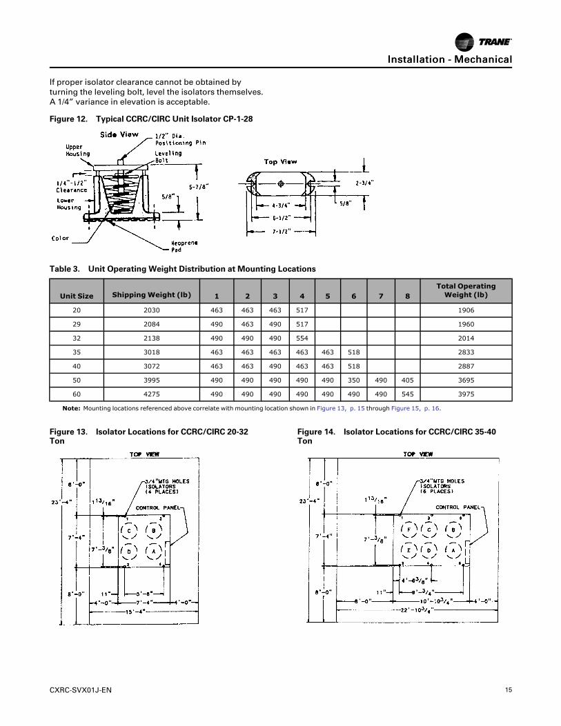
If proper isolator clearance cannot be obtained byturning the leveling bolt, level the isolators themselves.A 1/4” variance in elevation is acceptable.
Figure 12. Typical CCRC/CIRC Unit Isolator CP-1-28
Table 3. Unit Operating Weight Distribution at Mounting Locations
Unit Size ShippingWeight (lb) 1 2 3 4 5 6 7 8Total OperatingWeight (lb)
20 2030 463 463 463 517 1906
29 2084 490 463 490 517 1960
32 2138 490 490 490 554 2014
35 3018 463 463 463 463 463 518 2833
40 3072 463 463 490 463 463 518 2887
50 3995 490 490 490 490 490 350 490 405 3695
60 4275 490 490 490 490 490 490 490 545 3975
Note: Mounting locations referenced above correlate with mounting location shown in Figure 13, p. 15 through Figure 15, p. 16.
Figure 13. Isolator Locations for CCRC/CIRC 20-32Ton
Figure 14. Isolator Locations for CCRC/CIRC 35-40Ton
IInnssttaallllaattiioonn -- MMeecchhaanniiccaall

16 CXRC-SVX01J-EN
Figure 15. Isolator Locations for CCRC/CIRC 50-60Ton
Leveling the UnitBefore tightening down the mounting bolts, level theunit carefully. Use the unit base rail as a reference.Level the unit to within 1/4” over its entire length. Useshims if not using adjustable isolators.
Refrigerant PipingGeneral Refrigerant Recommendations
Liquid Line ComponentsIndoor portion of liquid line should include servicevalve, charging valve, thermal expansion valve, sightclass/moisture indicator, filter drier and solenoid valve.(Others as required by job specifications.) If the CCRC/CIRC is coupled with either SCRF/SIRF or SCRG/SIRG,these components are factory installed in the indoorunit, except filter driers which are ship-with, for fieldinstallation. CCRC/CIRC units also include a chargingvalve.
• Sight glass/moisture indicators aid introubleshooting, charging and servicing thesystem. Locate between filter drier and expansionvalve.
• Filter-driers are provided for field installation.Locate near evaporator.
• Solenoid valves should be located near theevaporator.
Discharge Line ComponentsIndoor portion of discharge line should include accessvalve and check valve. If the CCRC/CIRC is coupled witheither SCRF/SIRF or SCRG/SIRG, these components arefactory installed on the indoor unit. Install other
discharge line components as required by jobspecifications (hot gas mufflers, pipe anchors, oil traps,etc.) to provide proper system operation, preventexcessive vibration and assure proper oil return to thecompressor. Also recommended are discharge shutoffvalves in each hot gas line near the condenser tofacilitate refrigerant storage in the condenser duringservice procedures. When optional discharge line ballvalves are present in the indoor section, installation offield supplied discharge line access valves near theindoor unit may aid in installation and service.
NNOOTTIICCEECCoommpprreessssoorr DDaammaaggee!!FFaaiilluurree ttoo ffoollllooww iinnssttrruuccttiioonnss bbeellooww ccoouulldd rreessuulltt iinnccoommpprreessssoorr ddaammaaggee..TToo pprreevveenntt ppoossssiibbllee rreeffrriiggeerraanntt ddrraaiinn bbaacckk iinnttooccoommpprreessssoorr dduurriinngg ooffff ccyyccllee,, iiff nnoo ddiisscchhaarrggee cchheecckkvvaallvvee iiss uusseedd,, ddrroopp ddiisscchhaarrggee lliinnee wweellll bbeelloowwccoommpprreessssoorr ddiisscchhaarrggee lleevveell bbeeffoorree bbeeggiinnnniinnggvveerrttiiccaall rriissee..
NNoottee:: See Figure 16, p. 16 for a typical refrigerantpiping configuration that may be used in place ofa double riser system (not recommended). Thisarrangement assures adequate oil return to thesuction line, even at partial load conditions.Refer to Trane Air Conditioning Manual for morespecific piping recommendations.
Figure 16. Typical Configuration for Constant DrainOil Trap
Refrigerant Piping RecommendationIsolate refrigerant lines from the building to preventtransferring line vibration to the structure. Do notsecure lines rigidly to the structure at any point, as thiswill defeat the unit isolation system.
IInnssttaallllaattiioonn -- MMeecchhaanniiccaall

CXRC-SVX01J-EN 17
Interconnecting PipingRefrigerant piping must be properly sized and applied.These two factors have significant effect on bothsystem performance and reliability.
IImmppoorrttaanntt:: Cleanliness is extremely important duringsystem installation to minimize residualcontaminants, such as oxidization andscale.
• See Table 4, p. 17 for recommended discharge andliquid line sizes. Table also includes unitconnections sizes.
• Verify compressor oil levels are near top of sightglass or above.
• Verify remote condenser system is sealed bymomentarily depressing liquid line access port
valve. If holding charge is present, continue pipinginstallation. If not, locate and repair any leaks. Referto the sections,“Refrigerant Leak TestProcedure,” p. 25 and “System EvacuationProcedures,” p. 26.
• Work on only one circuit at a time to minimizesystem exposure to moisture in the air.
• Capped discharge and liquid line connections arelocated near bottom of the indoor unit, left side forSCRF/SIRF, right side for SCRG/SIRG. CCRC/CIRCconnections are located in the unit front at the top.
• Remove cap with a tube cutter to minimize risk ofgetting chips inside piping.
Table 4. Refrigerant Connection and Piping Sizes
Connection Size
CXRC SizeCircuit 1 Circuit 2
Liquid Discharge Liquid Discharge
20, 29, 32 5/8 in 7/8 in 5/8 in 7/8 in
35, 40, 50 7/8 in 1-3/8 in 5/8 in 7/8 in
60 7/8 in 1-3/8 in 5/8 in 7/8 in
SXRF SizeCircuit 1 Circuit 2
Liquid Discharge Liquid Discharge
20, 25, 29 5/8 in 7/8 in 5/8 in 7/8 in
30, 35, 40, 50 7/8 in 1-3/8 in 5/8 in 7/8 in
60 7/8 in 1-3/8 in 5/8 in 7/8 in
SXRG SizeCircuit 1 Circuit 2
Liquid Discharge Liquid Discharge
20, 25, 32 5/8 in 7/8 in 5/8 in 7/8 in
Interconnecting Tube
SXRF/CXRC SizeCircuit 1 Circuit 2
Liquid Discharge Liquid Discharge
20/20 5/8 7/8 in 5/8 in 7/8 in
25/29 5/8 1-1/8 in 5/8 in 7/8 in
29/29 5/8 1-1/8 in 5/8 in 7/8 in
30/35 7/8 1-1/8 in 5/8 in 7/8 in
35/35 7/8 1-1/8 in 5/8 in 7/8 in
40/40 7/8 1-3/8 in(a) 5/8 in 7/8 in
50/50 7/8 1-3/8 in 5/8 in 1-1/8 in
60/60 7/8 1 3/8 in 7/8 in 1-3/8 in
IInnssttaallllaattiioonn -- MMeecchhaanniiccaall
18 CXRC-SVX01J-EN
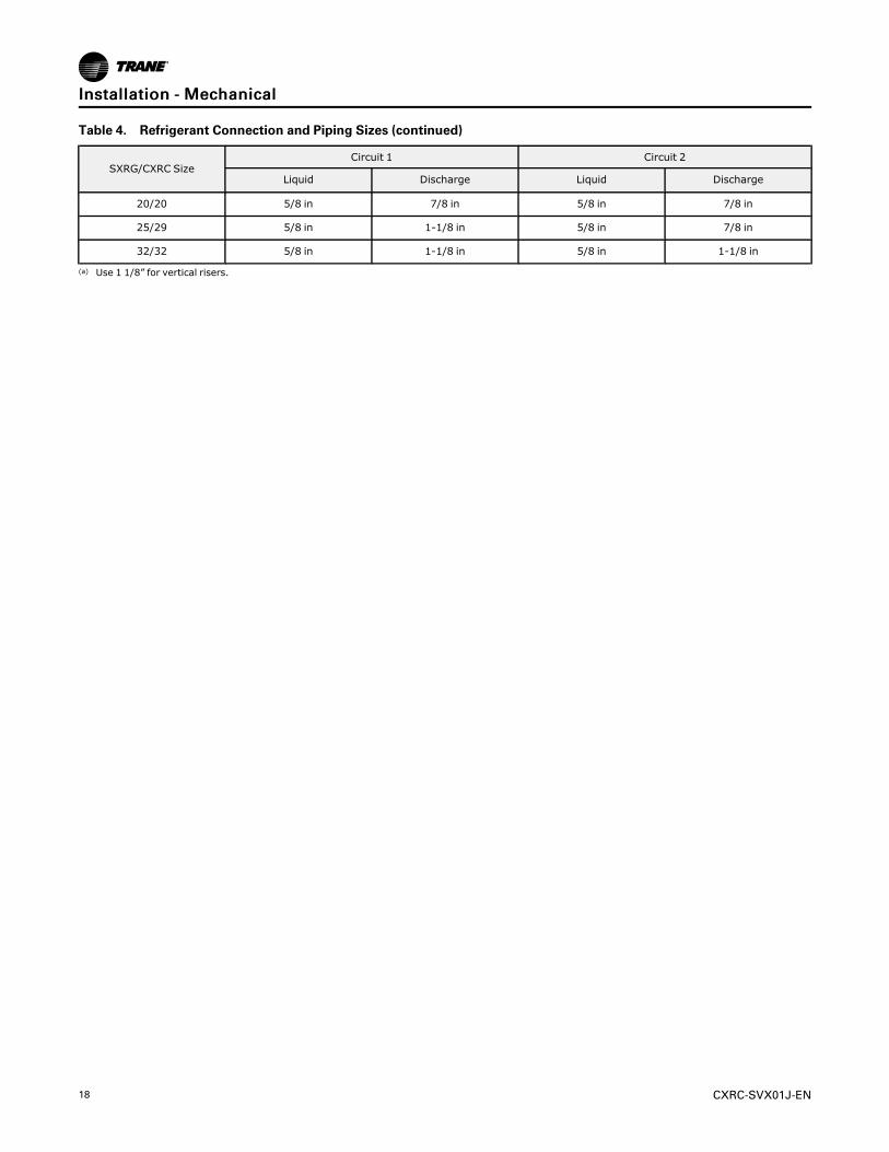
Table 4. Refrigerant Connection and Piping Sizes (continued)
SXRG/CXRC SizeCircuit 1 Circuit 2
Liquid Discharge Liquid Discharge
20/20 5/8 in 7/8 in 5/8 in 7/8 in
25/29 5/8 in 1-1/8 in 5/8 in 7/8 in
32/32 5/8 in 1-1/8 in 5/8 in 1-1/8 in
(a) Use 1 1/8” for vertical risers.
IInnssttaallllaattiioonn -- MMeecchhaanniiccaall
CXRC-SVX01J-EN 19
Installation — ElectricalGeneral ElectricalRecommendations
WWAARRNNIINNGGHHaazzaarrddoouuss SSeerrvviiccee PPrroocceedduurreess!!FFaaiilluurree ttoo ffoollllooww aallll pprreeccaauuttiioonnss iinn tthhiiss mmaannuuaall aannddoonn tthhee ttaaggss,, ssttiicckkeerrss,, aanndd llaabbeellss ccoouulldd rreessuulltt iinnddeeaatthh oorr sseerriioouuss iinnjjuurryy..TTeecchhnniicciiaannss,, iinn oorrddeerr ttoo pprrootteecctt tthheemmsseellvveess ffrroommppootteennttiiaall eelleeccttrriiccaall,, mmeecchhaanniiccaall,, aanndd cchheemmiiccaallhhaazzaarrddss,, MMUUSSTT ffoollllooww pprreeccaauuttiioonnss iinn tthhiiss mmaannuuaallaanndd oonn tthhee ttaaggss,, ssttiicckkeerrss,, aanndd llaabbeellss,, aass wweellll aass tthheeffoolllloowwiinngg iinnssttrruuccttiioonnss:: UUnnlleessss ssppeecciiffiieedd ootthheerrwwiissee,,ddiissccoonnnneecctt aallll eelleeccttrriiccaall ppoowweerr iinncclluuddiinngg rreemmootteeddiissccoonnnneecctt aanndd ddiisscchhaarrggee aallll eenneerrggyy ssttoorriinnggddeevviicceess ssuucchh aass ccaappaacciittoorrss bbeeffoorree sseerrvviicciinngg..FFoollllooww pprrooppeerr lloocckkoouutt//ttaaggoouutt pprroocceedduurreess ttooeennssuurree tthhee ppoowweerr ccaann nnoott bbee iinnaaddvveerrtteennttllyyeenneerrggiizzeedd.. WWhheenn nneecceessssaarryy ttoo wwoorrkk wwiitthh lliivveeeelleeccttrriiccaall ccoommppoonneennttss,, hhaavvee aa qquuaalliiffiieedd lliicceennsseeddeelleeccttrriicciiaann oorr ootthheerr iinnddiivviidduuaall wwhhoo hhaass bbeeeennttrraaiinneedd iinn hhaannddlliinngg lliivvee eelleeccttrriiccaall ccoommppoonneennttssppeerrffoorrmm tthheessee ttaasskkss..
NNOOTTIICCEEUUssee CCooppppeerr CCoonndduuccttoorrss OOnnllyy!!FFaaiilluurree ttoo uussee ccooppppeerr ccoonndduuccttoorrss ccoouulldd rreessuulltt iinneeqquuiippmmeenntt ddaammaaggee aass tthhee eeqquuiippmmeenntt wwaass nnoottddeessiiggnneedd oorr qquuaalliiffiieedd ttoo aacccceepptt ootthheerr ttyyppeess ooffccoonndduuccttoorrss..
All wiring and disconnects must comply with local andNational Electrical Codes™ (NEC). The installer mustprovide properly sized system interconnection andpower supply wiring with appropriate fused disconnectswitches.
Electrical connection types, sizes, and locations areshown in Figure 5, p. 10. Refer toTable 5, p. 20 forelectrical data (MCA, MFS). This information is alsoprovided on the unit nameplate. Sample wiringdiagrams are provided in this manual.
Power Supply WiringRun appropriately sized power wiring and field-supplied conduit through the line voltage accessopening provided on the front of the unit. Refer toFigure 1, p. 7 for electrical connection locations. Runwire and field supplied conduit up to the conduitconnection point located in the bottom of the controlpanel. Make appropriate connections to the powerterminal block in the control panel. Install fuseddisconnects as required by local codes. Provide properequipment ground to the ground connections in thecontrol panel.
System Interconnection WiringRun appropriately sized field supplied conduits, 115and 24 volt control wiring through the 115 and 24 voltaccess openings provided on the front of the unit. Referto Figure 5, p. 10 for electrical connection locations.Run wire and field supplied conduit to the conduitconnection points provided on the bottom of thecontrol panel. Make appropriate connections to theterminal blocks in the control panel. Install safetydevices if required by local code. Provide properequipment ground to the ground connections in thecontrol panel. Refer to Table 5, p. 20 for electrical data.
Unit Wiring DiagramsSpecific unit wiring diagrams are provided on theinside of the control panel door. Use these diagramsfor connections or trouble analysis. Refer to thesection, “Wiring Diagrams,” p. 31, for typical unitwiring diagrams.
Unit VoltageElectrical power to the unit must meet stringentrequirements for the unit to operate properly. Totalvoltage supply and voltage imbalance between phasesmust be within the following tolerances as statedbelow in the section, “VVoollttaaggee IImmbbaallaannccee” .
Voltage Supply
WWAARRNNIINNGGLLiivvee EElleeccttrriiccaall CCoommppoonneennttss!!FFaaiilluurree ttoo ffoollllooww aallll eelleeccttrriiccaall ssaaffeettyy pprreeccaauuttiioonnsswwhheenn eexxppoosseedd ttoo lliivvee eelleeccttrriiccaall ccoommppoonneennttss ccoouullddrreessuulltt iinn ddeeaatthh oorr sseerriioouuss iinnjjuurryy..WWhheenn iitt iiss nneecceessssaarryy ttoo wwoorrkk wwiitthh lliivvee eelleeccttrriiccaallccoommppoonneennttss,, hhaavvee aa qquuaalliiffiieedd lliicceennsseedd eelleeccttrriicciiaannoorr ootthheerr iinnddiivviidduuaall wwhhoo hhaass bbeeeenn pprrooppeerrllyy ttrraaiinneeddiinn hhaannddlliinngg lliivvee eelleeccttrriiccaall ccoommppoonneennttss ppeerrffoorrmmtthheessee ttaasskkss..
NNOOTTIICCEEMMoottoorr DDaammaaggee!!CCoorrrreecctt pphhaassee sseeqquueennccee iiss ccrriittiiccaall.. IIff pphhaasseesseeqquueennccee ooff tthhee iinnccoommiinngg lliinnee vvoollttaaggee iiss nnoottccoorrrreecctt,, iitt ccoouulldd rreessuulltt iinn mmoottoorr ddaammaaggee..
Measure each leg of supply voltage at the line voltagedisconnect switch. Readings must fall within voltageutilization range shown on the unit nameplate. Ifvoltage of any leg does not fall within tolerance, notifythe power company to correct this situation beforeoperating the unit. Inadequate voltage to the unit can

20 CXRC-SVX01J-EN
cause control components to malfunction and shortenthe life of relay contacts and condenser fan motors.
Voltage ImbalanceExcessive voltage imbalance between phases in athree-phase system can cause motors to overheat andeventually fail. Maximum allowable imbalance is 2%.Voltage imbalance is defined as 100 times themaximum deviation of the three voltages (threephases) subtracted from the average (without regard tosign) divided by the average voltage.
EExxaammppllee
• L1 measured = 221 V
• L2 measured = 230 V
• L3 measured = 227 V
221 + 230 + 227
3= 2.2%
NNoottee:: L1 = 221 volts is the maximum deviation of the 3voltages from the average of the 3 voltages.
Therefore, the imbalance percentage is:
100 (226 - 221)
226= 2.2%
The 2.2 % imbalance that exists in the example aboveexceeds the maximum allowable imbalance betweenphases.
Table 5. CCRC/CIRC Condenser Electrical Data
Tons Voltage # Fans FLA (ea.) LRA (ea.) MCA MCB
20, 29, 32
200 4 4.1 20.7 17.4 20
460 4 1.8 9 7.7 15
575 4 1.4 7.2 5.9 15
35, 40
200 6 4.1 20.7 25.6 30
460 6 1.8 9 11.2 15
575 6 1.4 7.2 8.8 15
50, 60
200 8 4.1 20.7 33.8 40
460 8 1.8 9 14.8 15
575 8 1.4 7.2 11.5 15
Note: All motors for CCRC/CIRC units are rated at 1 hp (0.7457 kW).
IInnssttaallllaattiioonn —— EElleeccttrriiccaall

CXRC-SVX01J-EN 21
Operating PrinciplesControl Sequences of Operationfor Units with IntelliPakTypical Unit OperationSequence of operation will be described for a 60-tonCCRC condenser attached to a 60-ton IntelliPakcontrolled SCRF. All other configurations should bediscernible once the operator understands thissequence.
When evaporator unit calls for mechanical cooling, thecompressor starts. The IntelliPak controller then startsreading saturated condenser temperature sensor forthe circuit that started. Saturated condensertemperature sensor probes are factory installed on thecondensing coils of the CCRC condensing unit.
When condenser temperature rises to a point thatcondensing is required, the IntelliPak controllerinitiates a call for condenser operation. Upon initialstart-up, the IntelliPak controller pulls in K1 and K2relays simultaneously, thus pulling on all fans in circuit1.
Condensing temperatures should then begin to fall ascondensing begins. As the temperature falls, the K1relay drops out, thus dropping out circuit 1A fan 1 and2 contactors and stopping circuit 1A fans 1 and 2. (TheIntelliPak controller will try to maintain a factory defaultcondensing temperature setpoint of 105°F.)
If saturated condenser temperatures continue to fallwith only circuit 1B fans 1 and 2 fans running, K2 relaydrops out and K1 relay re-engages. (See stages of fanoperation on CCRC schematics). K1 relay engagescircuit 1A fan 1 contactor, starting circuit 1A fan 1 only.(Circuit 1B fan 1, 2 auxiliary contactor is no longerengaged.)
If saturated temperature continues to drop with onlycircuit 1A fan 1 running, the low ambient damper (ifequipped) begins to throttle the airflow to maintainsaturated condensing temperature. The SCRF actuatesthe damper by way of a 2-10 VDC signal to the lowambient damper actuator, thus maintaining headpressure in a low ambient condition. The unitcontinues to operate in this low ambient condition untilthe cooling setpoint is satisfied, at which time, the unitstops and halts all calls for condenser fan operation oruntil the saturated condenser temperature begins torise.
If saturated condenser temperature begins to rise, lowambient damper modulates open to allow moreairflow. If saturated condenser temperature continuesto rise with damper modulated fully open, K1 relaydrops out and the IntelliPak controller pulls in K2 relay,subsequently pulling in contactor Circuit 1B fan 1, 2
auxiliary contactor. Upon closure of this contactor,circuit 1B fans 1 and 2 start. (See stages of fanoperation on CCRC schematics).
There is no low ambient operation associated withcircuit 1B fans 1 and 2 operation. However thesaturated condenser temperature sensor continues tomonitor condensing temperature in order to make thenecessary adjustments to the fan operation. TheIntelliPak controller continually samples saturatedcondenser temperature and stages up or down the fansas required to maintain saturated condensingtemperature as read by the saturated condensertemperature sensor probes (see stages of fan operationon CCRC schematics).
If saturated condenser temperature continues to risewith only K2 relay pulled in, the K1 relay re-engagesand again pulls in circuit 1A fan 1 contactor.
NNoottee:: Circuit 1B fan 1, 2 auxiliary contactor is nowpulled in and will pull in circuit 1A fan 2contactor, starting circuit 1A fan 2.
K1 and K2 relays are now simultaneously engaged thusstarting all fan operation in circuit 1. The unit stagesdown in the reverse manner based on saturatedcondensing temperature if and when saturatedcondenser temperature begins to fall.
This is a detailed sequence of operation for the firstcircuit to begin operation. If cooling load demandsrequire the second circuit to operate, the samesequence of operation is valid and takes placesimultaneously utilizing IntelliPak controller relays K5and K6.
Similar sequence of operation takes place on otherCCRC condensing unit sizes. Refer to the schematics,including stages of fan operation, for specific unitinstalled.
NNoottee:: Low ambient dampers are optional. Not all unitsmay be equipped with low ambient dampers.
Low Ambient Damper OperationUnits with low ambient operation have two (2) lowambient dampers. The dampers are used to extendoperation from standard low limit temperature to aminimum of 0°F. Dampers modulate airflow acrosscondenser coils to maintain condensing pressureduring low ambient operation.
Optional low ambient (LA) dampers are controlled bylow ambient damper control module mounted incontrol panel inside CCRC unit on a thermostatcontrolled unit, or by the IntelliPak controller of SCRFor SCRG.

22 CXRC-SVX01J-EN
Condenser Fan OperationAll condenser fans are direct-drive, 26” propeller andare driven by one motor horsepower. Fan operation onall units is interlocked with compressor start and stop.
They use customer-provided compressor contactorauxiliary contacts and liquid line pressure if thethermostat-controlled unit is used as the evaporator, orby IntelliPak controller if using a SCRF or SCRG.
OOppeerraattiinngg PPrriinncciipplleess
CXRC-SVX01J-EN 23
Pre-Start Checklist
After the unit is installed, complete each step in thechecklist that follows and check off each step ascompleted. When all are accomplished, the unit isready to be started.
☐ Inspect all wiring connections. Connections should beclean and tight.
☐ Check voltage to the unit at the line power fuseddisconnect. Voltage must be within the voltage utilizationrange given on the unit nameplate. Voltage imbalancemust not exceed two percent. Refer to the “VoltageImbalance,” p. 20.
☐ Check condenser fans. Condenser fan blades shouldrotate freely in the fan orifices and should be mountedsecurely on the motor shafts.
☐ Check condenser coils. Coil fins should be clean andstraight. There should be no restrictions to proper airflowthrough the condenser.
☐ Evacuate the refrigerant system. See Maintenance chapterof unit IOM (SSCCXXFF--SSVVXX0011**--EENN or SSCCXXGG--SSVVXX0011**--EENN forevacuation and procedure.
☐ Once the system is properly evacuated, charge eachcircuit with proper amount of refrigerant.
☐ Refer to the Mechanical and Start-up sections in theInstallation, Operation, and Maintenance Manuals (SSCCXXFF--SSVVXX0011 and or SSCCXXGG--SSVVXX0011 for refrigerant chargingprocedures).
☐ Prepare remainder of system for operation andcoordinate condenser start up with evaporator unitstartup.
24 CXRC-SVX01J-EN
Startup and ShutdownStartup
WWAARRNNIINNGGLLiivvee EElleeccttrriiccaall CCoommppoonneennttss!!FFaaiilluurree ttoo ffoollllooww aallll eelleeccttrriiccaall ssaaffeettyy pprreeccaauuttiioonnsswwhheenn eexxppoosseedd ttoo lliivvee eelleeccttrriiccaall ccoommppoonneennttss ccoouullddrreessuulltt iinn ddeeaatthh oorr sseerriioouuss iinnjjuurryy..WWhheenn iitt iiss nneecceessssaarryy ttoo wwoorrkk wwiitthh lliivvee eelleeccttrriiccaallccoommppoonneennttss,, hhaavvee aa qquuaalliiffiieedd lliicceennsseedd eelleeccttrriicciiaannoorr ootthheerr iinnddiivviidduuaall wwhhoo hhaass bbeeeenn pprrooppeerrllyy ttrraaiinneeddiinn hhaannddlliinngg lliivvee eelleeccttrriiccaall ccoommppoonneennttss ppeerrffoorrmmtthheessee ttaasskkss..
NNOOTTIICCEECCoommpprreessssoorr DDaammaaggee!!FFaaiilluurree ttoo ffoollllooww iinnssttrruuccttiioonnss bbeellooww wwiillll ccaauussee tthheeccoommpprreessssoorr ttoo ooppeerraattee iinn aa vvaaccuuuumm aanndd rreessuulltt iinnccoommpprreessssoorr ddaammaaggee..NNeevveerr mmaannuuaallllyy oorr aauuttoommaattiiccaallllyy ppuummpp ddoowwnnssyysstteemm bbeellooww 77 ppssiigg..
NNOOTTIICCEECCoommpprreessssoorr DDaammaaggee!!FFaaiilluurree ttoo ffoollllooww iinnssttrruuccttiioonnss ccoouulldd rreessuulltt iinnccoommpprreessssoorr ddaammaaggee..KKeeeepp ccrraannkkccaassee hheeaatteerrss oonn wwhheenneevveerr rreeffrriiggeerraanntt iissiinn tthhee ssyysstteemm..IIff ccrraannkkccaassee hheeaatteerrss hhaavvee nnoott bbeeeenn oonn wwiitthhrreeffrriiggeerraanntt iinn tthhee ssyysstteemm,, ttuurrnn tthhee ccrraannkkccaasseehheeaatteerrss oonn ffoorr aa mmiinniimmuumm ooff 2244 hhoouurrss bbeeffoorreessttaarrttiinngg ccoommpprreessssoorrss..
When wired properly, the unit cycles condenser fans inresponse to compressor interlock or the IntelliPakcontroller output. The IntelliPak controller readssaturated refrigerant temperatures and cycles the fansappropriately. Refer to the section, “WiringDiagrams,” p. 31.
Normal Unit Shut DownThe unit can be stopped by opening the unit powersupply disconnect switch. However, normally the unitoperation stops due to interruption of the coolingdemand signal by the circuit cooling relays. The CCRC/
CIRC condensing unit should be shutdown by firstshutting down the indoor evaporative cooling unit. Bystopping the indoor unit, the request for condensinghas been terminated, thus stopping all condenser fans.The disconnect switch on the CCRC/CIRC unit powersupply should then be opened. By not shutting downthe evaporator unit first before the condenser unitresults in a high-pressure situation and should beavoided if possible.
Seasonal Shut DownIf the unit will be inoperative for an extended period,lock out unit operation by disconnecting thecompressor interlock circuits and opening and lockingthe main power disconnect switch.
If desired, large amounts of liquid refrigerant can beisolated and stored in the condenser by closing theliquid line service valves and operating thecompressors to pump the refrigerant into thecondenser and then valving off the hot gas line nearthe condenser coil.
Seasonal Startup1. Inspect the interior of the unit for debris.
2. Check control panel wiring connections forcorrosion and proper security. Check control paneldoor for proper weather seal.
3. Inspect condenser fans. Blades must be secure onfan shaft and rotate freely.
4. Inspect coil for obstructions and cleanliness. Cleancoil if required.
5. Inspect low ambient dampers. Damper blades mustbe properly aligned, free from obstructions andoperate freely. You may have to disconnectactuator linkage to inspect damper movement.
6. Close unit power supply disconnect switch.
7. Allow 24 hours of crankcase operation beforestarting compressors. Crankcase heaters areenergized whenever the unit disconnect is closedand the compressors are off.
The unit should now operate properly in response tocooling demand at the system thermostat.

CXRC-SVX01J-EN 25
MaintenanceRead the following Warnings and Cautions beforebeginning any maintenance procedures.
WWAARRNNIINNGGHHaazzaarrddoouuss SSeerrvviiccee PPrroocceedduurreess!!FFaaiilluurree ttoo ffoollllooww aallll pprreeccaauuttiioonnss iinn tthhiiss mmaannuuaall aannddoonn tthhee ttaaggss,, ssttiicckkeerrss,, aanndd llaabbeellss ccoouulldd rreessuulltt iinnddeeaatthh oorr sseerriioouuss iinnjjuurryy..TTeecchhnniicciiaannss,, iinn oorrddeerr ttoo pprrootteecctt tthheemmsseellvveess ffrroommppootteennttiiaall eelleeccttrriiccaall,, mmeecchhaanniiccaall,, aanndd cchheemmiiccaallhhaazzaarrddss,, MMUUSSTT ffoollllooww pprreeccaauuttiioonnss iinn tthhiiss mmaannuuaallaanndd oonn tthhee ttaaggss,, ssttiicckkeerrss,, aanndd llaabbeellss,, aass wweellll aass tthheeffoolllloowwiinngg iinnssttrruuccttiioonnss:: UUnnlleessss ssppeecciiffiieedd ootthheerrwwiissee,,ddiissccoonnnneecctt aallll eelleeccttrriiccaall ppoowweerr iinncclluuddiinngg rreemmootteeddiissccoonnnneecctt aanndd ddiisscchhaarrggee aallll eenneerrggyy ssttoorriinnggddeevviicceess ssuucchh aass ccaappaacciittoorrss bbeeffoorree sseerrvviicciinngg..FFoollllooww pprrooppeerr lloocckkoouutt//ttaaggoouutt pprroocceedduurreess ttooeennssuurree tthhee ppoowweerr ccaann nnoott bbee iinnaaddvveerrtteennttllyyeenneerrggiizzeedd.. WWhheenn nneecceessssaarryy ttoo wwoorrkk wwiitthh lliivveeeelleeccttrriiccaall ccoommppoonneennttss,, hhaavvee aa qquuaalliiffiieedd lliicceennsseeddeelleeccttrriicciiaann oorr ootthheerr iinnddiivviidduuaall wwhhoo hhaass bbeeeennttrraaiinneedd iinn hhaannddlliinngg lliivvee eelleeccttrriiccaall ccoommppoonneennttssppeerrffoorrmm tthheessee ttaasskkss..
Refrigerant SystemRefrigerant Leak Test Procedure
WWAARRNNIINNGGCCoonnffiinneedd SSppaaccee HHaazzaarrddss!!FFaaiilluurree ttoo ffoollllooww iinnssttrruuccttiioonnss bbeellooww ccoouulldd rreessuulltt iinnddeeaatthh oorr sseerriioouuss iinnjjuurryy..DDoo nnoott wwoorrkk iinn ccoonnffiinneedd ssppaacceess wwhheerree rreeffrriiggeerraannttoorr ootthheerr hhaazzaarrddoouuss,, ttooxxiicc oorr ffllaammmmaabbllee ggaass mmaayy bbeelleeaakkiinngg.. RReeffrriiggeerraanntt oorr ootthheerr ggaasseess ccoouulldd ddiissppllaacceeaavvaaiillaabbllee ooxxyyggeenn ttoo bbrreeaatthhee,, ccaauussiinngg ppoossssiibblleeaasspphhyyxxiiaattiioonn oorr ootthheerr sseerriioouuss hheeaalltthh rriisskkss.. SSoommeeggaasseess mmaayy bbee ffllaammmmaabbllee aanndd oorr eexxpplloossiivvee.. IIff aa lleeaakkiinn ssuucchh ssppaacceess iiss ddeetteecctteedd,, eevvaaccuuaattee tthhee aarreeaaiimmmmeeddiiaatteellyy aanndd ccoonnttaacctt tthhee pprrooppeerr rreessccuuee oorrrreessppoonnssee aauutthhoorriittyy..
WWAARRNNIINNGGEExxpplloossiioonn HHaazzaarrdd!!FFaaiilluurree ttoo ffoollllooww ssaaffee lleeaakk tteesstt pprroocceedduurreess bbeelloowwccoouulldd rreessuulltt iinn ddeeaatthh oorr sseerriioouuss iinnjjuurryy oorreeqquuiippmmeenntt oorr pprrooppeerrttyy--oonnllyy--ddaammaaggee..NNeevveerr uussee aann ooppeenn ffllaammee ttoo ddeetteecctt ggaass lleeaakkss.. UUssee aalleeaakk tteesstt ssoolluuttiioonn ffoorr lleeaakk tteessttiinngg..
WWAARRNNIINNGGEExxpplloossiioonn HHaazzaarrdd!!FFaaiilluurree ttoo ffoollllooww tthheessee iinnssttrruuccttiioonnss ccoouulldd rreessuulltt iinnddeeaatthh oorr sseerriioouuss iinnjjuurryy oorr eeqquuiippmmeenntt oorr pprrooppeerrttyy--oonnllyy ddaammaaggee..UUssee oonnllyy ddrryy nniittrrooggeenn wwiitthh aa pprreessssuurree rreegguullaattoorr ffoorrpprreessssuurriizziinngg uunniitt.. DDoo nnoott uussee aacceettyylleennee,, ooxxyyggeenn oorrccoommpprreesssseedd aaiirr oorr mmiixxttuurreess ccoonnttaaiinniinngg tthheemm ffoorrpprreessssuurree tteessttiinngg.. DDoo nnoott uussee mmiixxttuurreess ooff aahhyyddrrooggeenn ccoonnttaaiinniinngg rreeffrriiggeerraanntt aanndd aaiirr aabboovveeaattmmoosspphheerriicc pprreessssuurree ffoorr pprreessssuurree tteessttiinngg aass tthheeyymmaayy bbeeccoommee ffllaammmmaabbllee aanndd ccoouulldd rreessuulltt iinn aanneexxpplloossiioonn.. RReeffrriiggeerraanntt,, wwhheenn uusseedd aass aa ttrraaccee ggaasssshhoouulldd oonnllyy bbee mmiixxeedd wwiitthh ddrryy nniittrrooggeenn ffoorrpprreessssuurriizziinngg uunniittss..
WWAARRNNIINNGGEExxpplloossiioonn HHaazzaarrdd!!FFaaiilluurree ttoo ffoollllooww iinnssttrruuccttiioonn bbeellooww ccoouulldd rreessuulltt iinnddeeaatthh oorr sseerriioouuss iinnjjuurryy..DDoo nnoott eexxcceeeedd uunniitt nnaammeeppllaattee ddeessiiggnn pprreessssuurreesswwhheenn lleeaakk tteessttiinngg ssyysstteemm..
WWAARRNNIINNGGRR--441100AA RReeffrriiggeerraanntt uunnddeerr HHiigghheerrPPrreessssuurree tthhaann RR--2222!!FFaaiilluurree ttoo uussee pprrooppeerr eeqquuiippmmeenntt oorr ccoommppoonneennttss aassddeessccrriibbeedd bbeellooww,, ccoouulldd rreessuulltt iinn eeqquuiippmmeenntt ffaaiilliinnggaanndd ppoossssiibbllyy eexxppllooddiinngg,, wwhhiicchh ccoouulldd rreessuulltt iinnddeeaatthh,, sseerriioouuss iinnjjuurryy,, oorr eeqquuiippmmeenntt ddaammaaggee..TThhee uunniittss ddeessccrriibbeedd iinn tthhiiss mmaannuuaall uussee RR--441100AArreeffrriiggeerraanntt wwhhiicchh ooppeerraatteess aatt hhiigghheerr pprreessssuurreesstthhaann RR--2222.. UUssee OONNLLYY RR--441100AA rraatteedd sseerrvviicceeeeqquuiippmmeenntt oorr ccoommppoonneennttss wwiitthh tthheessee uunniittss.. FFoorrssppeecciiffiicc hhaannddlliinngg ccoonncceerrnnss wwiitthh RR--441100AA,, pplleeaasseeccoonnttaacctt yyoouurr llooccaall TTrraannee rreepprreesseennttaattiivvee..
NNoottee:: These service procedures require working withrefrigerant. Do not release refrigerant to theatmosphere. The service technician must complywith all federal, state, and local laws.
IImmppoorrttaanntt:: When Leak-testing refrigerant systems,observe all safety precautions. Leak testonly one circuit at a time to minimizesystem exposure to potentially harmfulmoisture in the air. Use R-410A refrigerantgas as a tracer for leak detection and useoil-pumped dry nitrogen to developrequired test pressures.
26 CXRC-SVX01J-EN
Field Piping (Air-Cooled Discharge/LiquidLines)1. Ensure all required field installed piping pressure
tests are completed in accordance with nationaland/or local codes.
2. Close liquid line angle valve.
3. Connect R-410A refrigerant cylinder to high sidecharging port (at Remote Condenser or fieldsupplied discharge line access port). Addrefrigerant to reach pressure of 12 to 15 psig.
4. Disconnect refrigerant cylinder. Connect drynitrogen cylinder to high side charging port andincrease pressure to 150 psig. Do not exceed highside (discharge) unit nameplate design pressure.Do not subject low side (suction) components tohigh side pressure.
5. Check all piping joints, valves, etc. for leaks.Recommend using electronic detector capable ofmeasuring 0.1 oz/year leak rate.
6. If a leak is located, use proper procedures toremove the refrigerant/nitrogen mixture, breakconnections and make repairs. Retest for leaks.
Ensure all service valves are open.
System Repair1. If system is water cooled with service valves, or air
cooled, high and low side may be testedindependently by closing liquid line angle valve andwater cooled unit discharge line ball valve.Otherwise leave all valves open and DO NOTexceed low side design pressure.
2. Connect R-410A refrigerant cylinder to chargingport, add refrigerant to reach pressure of 12 to 15psig.
3. Disconnect refrigerant cylinder. Connect drynitrogen cylinder to high side charging port andincrease pressure to 150 psig. DO NOT exceed unitnameplate design pressures. If testing completesystem, low side design pressure is maximum.
4. Check piping and/or components as appropriate forleaks.
5. Recommend using electronic detector capable ofmeasuring 0.1 oz/year leak rate.
6. If a leak is located, use proper procedures toremove the refrigerant/nitrogen mixture, breakconnections and make repairs. Retest for leaks.
Ensure all service valves are open.
System Evacuation Procedures1. Each refrigeration circuit must be evacuated before
the unit can be charged and started.
2. Use a rotary type vacuum pump capable of pullinga vacuum of 100 microns or less.
3. Verify that the unit disconnect switch and the
system control circuit switches are off.
4. Oil in the vacuum pump should be changed eachtime the pump is used with high quality vacuumpump oil. Before using any oil, check the oilcontainer for discoloration which usually indicatesmoisture in the oil and/or water droplets. Moisturein the oil adds to what must be removed from thesystem, increasing pump down time.
5. When connecting the vacuum pump to arefrigeration system, it is important to manifold thevacuum pump to both the high and low side of thesystem (liquid line access valve and suction lineaccess valve). Follow the pump manufacturer’sdirections for the proper methods of using thevacuum pump.
6. The lines used to connect the pump to the systemshould be copper and of the largest diameter thatcan practically be used. Using larger line sizes withminimum flow resistance can significantly reduceevacuation time.
IImmppoorrttaanntt:: Rubber or synthetic hoses are notrecommended for system evacuationbecause they have moisture absorbingcharacteristics which result in excessiverates of evaporation, causing pressurerise during the standing vacuum test.This makes it impossible to determine ifthe system has a leak, excessiveresidual moisture, or a continual or highrate of pressure increase due to thehoses.
7. An electronic micron vacuum gauge should beinstalled in the common line ahead of the vacuumpump shutoff valve, as shown in . Close Valves Band C, and open Valve A.
8. Start the vacuum pump, after several minutes, thegauge reading will indicate the maximum vacuumthe pump is capable of pulling. Rotary pumpsshould produce vacuums of 100 microns or less.
NNOOTTIICCEEMMoottoorr WWiinnddiinngg DDaammaaggee!!FFaaiilluurree ttoo ffoollllooww iinnssttrruuccttiioonnss bbeellooww ccoouulldd rreessuulltt iinnccoommpprreessssoorr mmoottoorr wwiinnddiinngg ddaammaaggee..DDoo nnoott uussee aa mmeeggoohhmm mmeetteerr oorr aappppllyy vvoollttaaggeeggrreeaatteerr tthhaann 5500 VVDDCC ttoo aa ccoommpprreessssoorr mmoottoorrwwiinnddiinngg wwhhiillee iitt iiss uunnddeerr aa ddeeeepp vvaaccuuuumm..
9. Open Valves B and C. Evacuate the system to apressure of 300 microns or less. As the vacuum isbeing pulled on the system, there could be a timewhen it would appear that no further vacuum isbeing obtained, yet, the pressure is high. It isrecommended that during the evacuation process,the vacuum be broken to facilitate the evacuationprocess.
10. To break the vacuum:
MMaaiinntteennaannccee
CXRC-SVX01J-EN 27
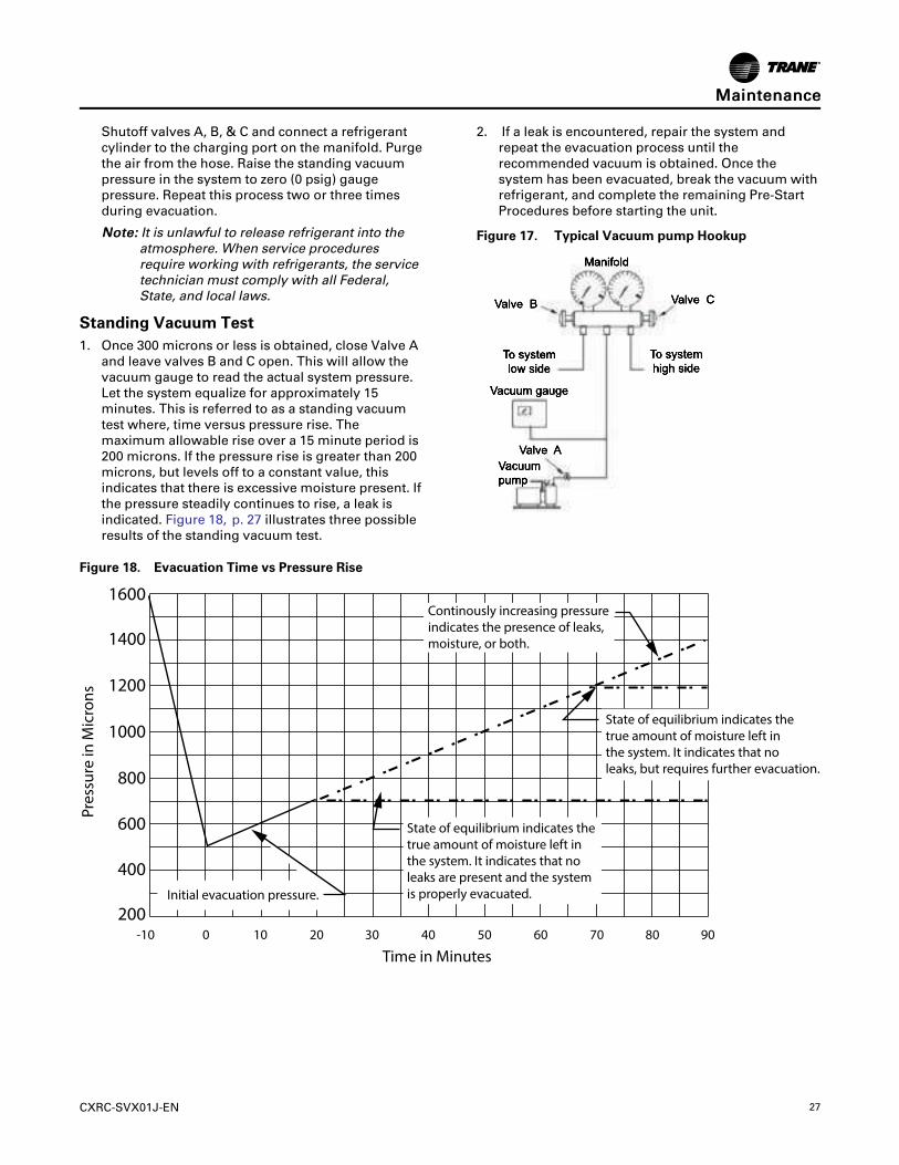
Shutoff valves A, B, & C and connect a refrigerantcylinder to the charging port on the manifold. Purgethe air from the hose. Raise the standing vacuumpressure in the system to zero (0 psig) gaugepressure. Repeat this process two or three timesduring evacuation.
NNoottee:: It is unlawful to release refrigerant into theatmosphere. When service proceduresrequire working with refrigerants, the servicetechnician must comply with all Federal,State, and local laws.
Standing Vacuum Test1. Once 300 microns or less is obtained, close Valve A
and leave valves B and C open. This will allow thevacuum gauge to read the actual system pressure.Let the system equalize for approximately 15minutes. This is referred to as a standing vacuumtest where, time versus pressure rise. Themaximum allowable rise over a 15 minute period is200 microns. If the pressure rise is greater than 200microns, but levels off to a constant value, thisindicates that there is excessive moisture present. Ifthe pressure steadily continues to rise, a leak isindicated. Figure 18, p. 27 illustrates three possibleresults of the standing vacuum test.
2. If a leak is encountered, repair the system andrepeat the evacuation process until therecommended vacuum is obtained. Once thesystem has been evacuated, break the vacuum withrefrigerant, and complete the remaining Pre-StartProcedures before starting the unit.
Figure 17. Typical Vacuum pump Hookup
Figure 18. Evacuation Time vs Pressure Rise
200
400
600
800
1000
1200
1400
1600
-10 0 10 20 30 40 50 60 70 80 90
Pres
sure
in M
icro
ns
Time in Minutes
Continously increasing pressureindicates the presence of leaks,moisture, or both.
Initial evacuation pressure.
State of equilibrium indicates thetrue amount of moisture left inthe system. It indicates that noleaks are present and the systemis properly evacuated.
State of equilibrium indicates thetrue amount of moisture left inthe system. It indicates that noleaks, but requires further evacuation.
MMaaiinntteennaannccee
28 CXRC-SVX01J-EN
Refrigerant Charging
CCAAUUTTIIOONNRReeffrriiggeerraanntt aatt FFrreeeezziinngg TTeemmppeerraattuurree!!DDiirreecctt ccoonnttaacctt wwiitthh lliiqquuiidd rreeffrriiggeerraanntt ccoouulldd rreessuullttiinn mmiinnoorr oorr mmooddeerraattee iinnjjuurryy..AAvvooiidd ccoonnttaacctt wwiitthh sskkiinn.. IIff wwoorrkkiinngg wwiitthh rreeffrriiggeerraannttiiss nneecceessssaarryy,, yyoouu MMUUSSTT wweeaarr aallll PPeerrssoonnaallPPrrootteeccttiivvee EEqquuiippmmeenntt ((PPPPEE)) iinncclluuddiinngg eeyyeepprrootteeccttiioonn,, ssaaffeettyy gglloovveess,, lloonngg sslleeeevveess,, aanndd ppaannttss..IInn ccaassee ooff ccoonnttaacctt,, ttrreeaatt tthhee iinnjjuurryy ssiimmiillaarr ttooffrroossttbbiittee.. SSlloowwllyy wwaarrmm tthhee aaffffeecctteedd aarreeaa wwiitthhlluukkeewwaarrmm wwaatteerr aanndd sseeeekk iimmmmeeddiiaattee mmeeddiiccaallaatttteennttiioonn..
NNOOTTIICCEECCoommpprreessssoorr DDaammaaggee!!EExxcceessssiivvee lliiqquuiidd aaccccuummuullaattiioonn iinn tthhee ssuuccttiioonn lliinneessccoouulldd rreessuulltt iinn ccoommpprreessssoorr ddaammaaggee..DDoo nnoott aallllooww lliiqquuiidd rreeffrriiggeerraanntt ttoo eenntteerr tthhee ssuuccttiioonnlliinnee..
IImmppoorrttaanntt:: For proper system operation, use onlyrefrigerant type listed on unit nameplate.
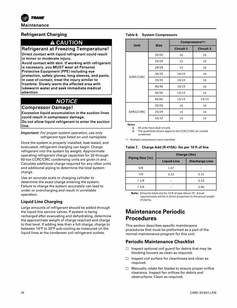
Once the system is properly installed, leak tested, andevacuated, refrigerant charging can begin. Chargerefrigerant into the system by weight. Approximateoperating refrigerant charge capacities for 20 through60-ton CCRC/CIRC condensing units are given in and .Calculate additional charge required for any other unitsand additional piping to determine the total systemcharge.
Use an accurate scale or charging cylinder todetermine the exact charge entering the system.Failure to charge the system accurately can lead tounder or overcharging and result in unreliableoperation.
Liquid Line ChargingLarge amounts of refrigerant should be added throughthe liquid line service valves. If system is beingrecharged after evacuating and dehydrating, determinethe approximate weight of charge required and chargeto that level. If adding less than a full charge, charge tobetween 14°F to 20°F sub-cooling as measured on theliquid lines at the condenser coil refrigerant outlets.
Table 6. System Compressors
Unit SizeCompressors(a)
Circuit 1 Circuit 2
SXRF/CXRC
20/20 10 10
25/29 15 10
29/29 15 10
30/35 10/10 10
35/35 10/10 10
40/40 10/15 10
50/50 15/15 10
60/60 15/15 15/15
SXRG/CXRC
20/20 10 10
25/29 15 10
32/32 15 15
Notes:1. All units have dual circuits2. The quantities shown apply to the CCRC/CIRC air-cooled
condenser
(a) Multiple compressors have manifold.
Table 7. Charge Add (R-410A)- lbs per 10 ft of line
Piping Size (in)Charge (lbs)
Liquid Line Discharge Line
5/8 1.07 -
7/8 2.23 0.31
1 1/8 - 0.53
1 3/8 - 0.80
Note: Amounts listed are for 10 ft of pipe above 25’. Actualrequirements will be in direct proportion to the actual lengthof piping.
Maintenance PeriodicProceduresThis section describes specific maintenanceprocedures that must be preformed as a part of thenormal maintenance program for this unit.
Periodic Maintenance Checklist☐ Inspect optional coil guard for debris that may be
blocking louvers as clean as required.
☐ Inspect coil surface for cleanliness and clean asrequired.
☐ Manually rotate fan blades to ensure proper orificeclearance. Inspect fan orifices for debris andobstructions. Clean as required.
MMaaiinntteennaannccee
CXRC-SVX01J-EN 29
Annual Maintenance Checklist☐ Perform all monthly maintenance inspections.
☐ Perform seasonal start up checks.
☐ Leak test refrigerant circuits. Inspect contacts of fan motorcontactors and relays. Replace all worn contacts.
☐ Clean condenser fans. Check fan assemblies for properorifice clearance, abnormal end play, and excessivevibration or noise. Fan motor bearings are permanentlylubricated and do not require lubrication.
☐ Have a qualified service technician check condenser fanpressure switches for proper operation (thermostatcontrolled unit only).
☐ Clean and repaint any corroded surface.
Cleaning the CoilClean the coil at least annually, or more frequently iflocated in a dirty environment, to help maintain properunit operating efficiency. High discharge pressures area good indication that the coil needs cleaning. Followthe detergent manufacturer instructions as closely aspossible to avoid potential damage to the coil.
WWAARRNNIINNGGHHaazzaarrddoouuss CChheemmiiccaallss!!CCooiill cclleeaanniinngg aaggeennttss ccaann bbee eeiitthheerr aacciiddiicc oorr hhiigghhllyyaallkkaalliinnee aanndd ccaann bbuurrnn sseevveerreellyy iiff ccoonnttaacctt wwiitthh sskkiinnoorr eeyyeess ooccccuurrss..HHaannddllee cchheemmiiccaall ccaarreeffuullllyy aanndd aavvooiidd ccoonnttaacctt wwiitthhsskkiinn.. AALLWWAAYYSS wweeaarr PPeerrssoonnaall PPrrootteeccttiivveeEEqquuiippmmeenntt ((PPPPEE)) iinncclluuddiinngg ggoogggglleess oorr ffaaccee sshhiieelldd,,cchheemmiiccaall rreessiissttaanntt gglloovveess,, bboooottss,, aapprroonn oorr ssuuiitt aassrreeqquuiirreedd.. FFoorr ppeerrssoonnaall ssaaffeettyy rreeffeerr ttoo tthhee cclleeaanniinnggaaggeenntt mmaannuuffaaccttuurreerr’’ss MMaatteerriiaallss SSaaffeettyy DDaattaa SShheeeettaanndd ffoollllooww aallll rreeccoommmmeennddeedd ssaaffee hhaannddlliinnggpprraaccttiicceess..
To clean the refrigerant coil, use a soft brush andsprayer, such as a garden pump up or high pressuretype. In addition, use a quality detergent; like SPREXAC, OAKITE 161 or OAKITE 166 and COILOX.
NNoottee:: If detergent is strongly alkaline (i.e. has a pHvalue greater that 8.5) after mixing, an aluminumcorrosion inhibitor must be added.
Coil Cleaning Procedure1. Disconnect power to the unit.
2. Remove enough panels and components from theunit to gain access to the coil.
3. Use a soft brush to remove loose dirt and debrisform both sides of the coil.
4. Straighten coil fins with fin comb as required.
5. Mix the detergent with water according to themanufacturers instructions.
NNoottee:: Observe all recommendations of the cleansermanufacturer. The coil cleanser manufacturer’srecommendations, warnings and cautions will atall times take precedence to these instructions.
WWAARRNNIINNGGHHaazzaarrddoouuss PPrreessssuurreess!!FFaaiilluurree ttoo ffoollllooww iinnssttrruuccttiioonnss bbeellooww ccoouulldd rreessuulltt iinnaa vviioolleenntt eexxpplloossiioonn,, wwhhiicchh ccoouulldd rreessuulltt iinn ddeeaatthh oorrsseerriioouuss iinnjjuurryy..IIff aa hheeaatt ssoouurrccee iiss rreeqquuiirreedd ttoo rraaiissee tthhee ttaannkkpprreessssuurree dduurriinngg rreemmoovvaall ooff rreeffrriiggeerraanntt ffrroommccyylliinnddeerrss,, uussee oonnllyy wwaarrmm wwaatteerr oorr hheeaatt bbllaannkkeettss ttoorraaiissee tthhee ttaannkk tteemmppeerraattuurree.. DDoo nnoott eexxcceeeedd aatteemmppeerraattuurree ooff 115500°°FF.. DDoo nnoott uunnddeerr aannyycciirrccuummssttaanncceess aappppllyy ddiirreecctt ffllaammee ttoo aannyy ppoorrttiioonn oofftthhee ccyylliinnddeerr..
6. Place solution in the sprayer. Use the followingguidelines if using a high-pressure sprayer:
• Minimum nozzle spray angle is 15°.
1.
2. Spray solution at 90° to the coil face.
3. Keep sprayer nozzle at least six inches form thecoil.
4. Sprayer pressure must not exceed 600 psi.
7. Spray leaving air side of the coil first then spray theentering air side of the coil. Allow the detergent andwater solution to stand on the coil for five minutes.
8. Rinse both sides of the coil with cool, clean water.
9. Inspect the coil. If it still appears dirty, repeat thecleaning procedure.
10. Reinstall all unit components and panels, andrestore electrical power to the unit.
Low Ambient Damper Adjustment
DDC Controlled UnitsInspect damper blade for proper alignment andoperation. Dampers should be fully closed whenpositioning signal from controller is 2 volts DC andshould be fully open when positioning signal fromcontroller is 10 volts DC. To adjust position removeVDC signal from actuator and check dampers to ensurefull closure. Check the 90% position open by applying a9-volt battery to the positioning signal. Dampersshould stroke 90% open when 9 VDC is applied to thepositioning signal inputs.
Thermostat Controlled UnitsThe same procedure can be used to inspect theoperation of the low ambient dampers on thethermostat-controlled unit. The difference is that thepositioning signal on the thermostat-controlled unitwill come from the control panel in the CCRC/CIRC unitnot from the IntelliPak controller. Inspect the operation
MMaaiinntteennaannccee

30 CXRC-SVX01J-EN
of the pressure switches. The switches should be openwhen sensing pressures less that 170 psig and shouldbe closed when sensing pressures greater than 265psig.
Troubleshooting
WWAARRNNIINNGGLLiivvee EElleeccttrriiccaall CCoommppoonneennttss!!FFaaiilluurree ttoo ffoollllooww aallll eelleeccttrriiccaall ssaaffeettyy pprreeccaauuttiioonnsswwhheenn eexxppoosseedd ttoo lliivvee eelleeccttrriiccaall ccoommppoonneennttss ccoouullddrreessuulltt iinn ddeeaatthh oorr sseerriioouuss iinnjjuurryy..WWhheenn iitt iiss nneecceessssaarryy ttoo wwoorrkk wwiitthh lliivvee eelleeccttrriiccaallccoommppoonneennttss,, hhaavvee aa qquuaalliiffiieedd lliicceennsseedd eelleeccttrriicciiaannoorr ootthheerr iinnddiivviidduuaall wwhhoo hhaass bbeeeenn pprrooppeerrllyy ttrraaiinneeddiinn hhaannddlliinngg lliivvee eelleeccttrriiccaall ccoommppoonneennttss ppeerrffoorrmmtthheessee ttaasskkss..
If operational difficulties are encountered, performthese preliminary checks before calling a servicetechnician:
☐ Check the system thermostat to ensure that all setpointsare set correctly and that thermostat is getting controlpower.
☐ Verify that the unit is receiving electrical supply power andthat all fuses are intact.
☐ Check the condenser for proper air flow and taketemperature readings across the condensing coils.
After completing the preliminary checks above, inspectthe unit for other obvious problems such as broken ordisconnected wires clogged grills or coils. If everythingappears to be in proper working order and the unit failsto operate properly, contact a qualified servicetechnician.
MMaaiinntteennaannccee

CXRC-SVX01J-EN 31
Wiring Diagrams
NNoottee:: Published unit wiring diagrams are available ine-library.
Drawing Number Description
2313-1633 Schematic; Power and Controls 20-60T IntelliPak
2313-1632 Schematic; Power and Controls 20-32T Thermostat Controls
2313-1635 Connections - Control Panel w/ Thermostat Controls
2313-1636 Connections - Control Panel w/ v Controls
2313-1637 Connections; Raceway 20-60T
2313-1639 Field Wiring Diagramw/ Thermostat Controls
2313-1640 Field Wiring Diagramw/ IntelliPak controls

Trane - by Trane Technologies (NYSE: TT), a global innovator - creates comfortable, energy efficientindoor environments for commercial and residential applications. For more information, please visittrane.com or tranetechnologies.com.
Trane has a policy of continuous product and product data improvements and reserves the right to change design and specifications withoutnotice. We are committed to using environmentally conscious print practices.
CXRC-SVX01J-EN 10 Apr 2020
Supersedes CXRC-SVX01H-EN (October 2017) ©2020 Trane