Embed Size (px)
Citation preview

461337 Out of Wall Fire and Combination Fire Smoke Dampers 1®
Document 461337OUT OF WALL FIRE AND
COMBINATION FIRE SMOKE DAMPERSODFD-XXX, OFD-XXX, OFSD-XXX SERIES
11⁄2 Hour Fire & Combination Fire Smoke Dampers Out of Wall or Out of Floor
Vertical and Horizontal Mount
Installation, Operation and Maintenance ManualPlease read and save these instructions for future reference. Read carefully before attempting to assemble, install, operate or maintain the product described. Protect yourself and others by observing all safety information. Failure to comply with instructions will result in voiding of the product warranty and may result in personal injury and/or property damage.
Table of ContentsGeneral Information ......................................2Pre-Installation Guidelines ............................2Electrical Guidelines ......................................2Installation ..................................................3-8 • Preparation of Openings ........................3 • Clearances Required Between Damper
Sleeves & Wall/Floor Openings .............4 • Inserting into Wall/Floor Openings .........4 • Securing the Damper/Sleeve
Assembly to Wall/Floor Openings .........5 • Duct to Sleeve Connection ..................6-7 • Actuator & Temperature Response
Device Connections ................................8Maintenance .................................................9Troubleshooting ............................................9Notes ......................................................10-12
These instructions apply to 11⁄2 hour rated fire and combination fire smoke dampers mounted in: 1) masonry, block, or stud walls and 2) concrete floors. Specific requirements in these instructions are mandatory. Dampers must be installed in accordance with these instructions to meet the requirements of UL 555 and/or UL 555S.Note: Combination fire smoke and fire dampers are manufactured and labeled for either vertical or horizontal installation. The dampers must be installed in accordance with labeling.
Receiving and HandlingUpon receiving dampers, check for both obvious and hidden damage. If damage is found, record all necessary information on the bill of lading and file a claim with the final carrier. Check to be sure that all parts of the shipment, including accessories, are accounted for.Dampers must be kept dry and clean. Indoor storage and protection from dirt, dust and the weather is highly recommended. Do not store at temperatures in excess of 100°F (38°C).
This manual is the property of the owner and is required for future maintenance. Please leave it with the owner when the job is complete.
Safety WarningImproper installation, adjustment, alteration, service or maintenance can cause property damage, injury or death. Read the installation, operating, and maintenance instructions thoroughly before installing or servicing this equipment.
®
461337 Out of Wall Fire and Combination Fire Smoke Dampers 2®
General Information
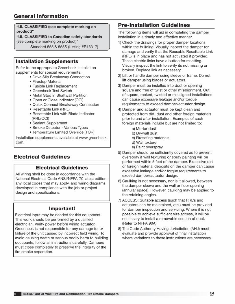
Electrical GuidelinesAll wiring shall be done in accordance with the National Electrical Code ANSI/NFPA-70 latest edition, any local codes that may apply, and wiring diagrams developed in compliance with the job or project design and specifications.
Important!Electrical input may be needed for this equipment. This work should be performed by a qualified electrician. Verify power before wiring actuator. Greenheck is not responsible for any damage to, or failure of the unit caused by incorrect field wiring. To avoid causing death or serious bodily harm to building occupants, follow all instructions carefully. Dampers must close completely to preserve the integrity of the fire smoke separation.
Electrical Guidelines
“UL CLASSIFIED (see complete marking on product)”“UL CLASSIFIED to Canadian safety standards (see complete marking on product)” Standard 555 & 555S (Listing #R13317)
The following items will aid in completing the damper installation in a timely and effective manner.1) Check the drawings for proper damper locations
within the building. Visually inspect the damper for damage and verify that the Reusable Resettable Link (RRL) is in place and has not activated if provided. These electric links have a button for resetting.Visually inspect the link to verify its not missing or broken. Replace link as necessary.
2) Lift or handle damper using sleeve or frame. Do not lift damper using blades or actuators.
3) Damper must be installed into duct or opening square and free of twist or other misalignment. Out of square, racked, twisted or misaligned installations can cause excessive leakage and/or torque requirements to exceed damper/actuator design.
4) Damper and actuator must be kept clean and protected from dirt, dust and other foreign materials prior to and after installation. Examples of such foreign materials include but are not limited to:
a) Mortar dust b) Drywall dust c) Firesafing materials d) Wall texture e) Paint overspray5) Damper should be sufficiently covered as to prevent
overspray if wall texturing or spray painting will be performed within 5 feet of the damper. Excessive dirt or foreign material deposits on the damper can cause excessive leakage and/or torque requirements to exceed damper/actuator design.
6) Caulking is not necessary, nor is it allowed, between the damper sleeve and the wall or floor opening (annular space). However, caulking may be applied to the retaining angles.
7) ACCESS: Suitable access (such that RRL’s and actuators can be maintained, etc.) must be provided for damper inspection and servicing. Where it is not possible to achieve sufficient size access, it will be necessary to install a removable section of duct. (Refer to NFPA 90A).
8) The Code Authority Having Jurisdiction (AHJ) must evaluate and provide approval of final installation where variations to these instructions are necessary.
Pre-Installation Guidelines
Installation SupplementsRefer to the appropriate Greenheck installation supplements for special requirements: • Drive Slip Breakaway Connection • Firestop Material • Fusible Link Replacement • Greenheck Test Switch • Metal Stud in Shaftwall Partition • Open or Close Indicator (OCI) • Quick Connect Breakaway Connection • Resettable Link (RRL) • Resettable Link with Blade Indicator (RRL/OCI) • Sealant Supplement • Smoke Detector - Various Types • Temperature Limited Override (TOR)Installation supplements available at www.greenheck.com.

461337 Out of Wall Fire and Combination Fire Smoke Dampers 3®
Preparation of Openings
• Frame wall openings as shown below (see Figure 1 & 2).• Gypsum wall board must be fastened 12 in. (305mm) on
center to all stud and runner flanges surrounding opening (see Figure 1 & 2).
• Prepare opening between studs and sleeve assembly as shown below (see Figure 3 & 4).
• All construction and fasteners must meet the requirements of the appropriate wall design (See UL Fire Resistance Directory) and/or local codes.
Figure 2
Second set of studs are not required on openings36 in. x 36 in. (914mm x 914mm) or smaller.
Metal stud only
Second set of studs are not required on openings36 in. x 36 in. (914mm x 914mm) or smaller.
Metal stud only
Wooden Stud Construction
Gypsum Wallboard
Stud or Runner
In wood stud construction, gypsum wallboard must coverall wood stud surfaces.
#10 sheet metal screws, 2 1/2 inches long, spaced 6 in. on center and maximum of 2 in. from corners (minimum of 2 screws per side). Screw into rear portion of the studs so as to avoid space conflicts with the grille assembly.
Figure 3 - Wood Stud
Steel stud
Flange
#10 2 1/2 in. long sheet metal screws spaced 6 in. on center and maximum of 2 in. from the corners (minimum of 2 screws per side) through the sleeve into the header, sill and jamb framing members. Screw into rear portion of the studs so as to avoid space conflicts with the grille assembly.
Figure 4 - Metal Stud
Figure 1
12 in.
24 in. o.c.Maximum
Floor Runner
Ceiling Runner24 in. o.c.Maximum
(metal studs)
24 in. o.c.Maximum
(metal studs)
16 in. o.c.Maximum
(wood studs)
16 in. o.c.Maximum
(wood studs)
2 in. (51mm)
2 in. (51mm)
2 Panhead Screws
Second set of studs are not required on openings 36 in. x 36 in. (914mm x 914mm) or smaller.

461337 Out of Wall Fire and Combination Fire Smoke Dampers 4®
Clearances Required Between Damper Sleeves & Wall/Floor Openings
Inserting Damper into Wall/Floor OpeningsFigures 5 - 7 show installations for grille access and continuing duct applications.The following maximum distances outside the barrier apply: • Steel stud and masonry barriers: - 81⁄2 in. (216mm) provided the width and height of the damper are both 24 in. (610mm) or less and the damper sleeve is 20 gauge - 71⁄2 in. (191mm) in all other instances • Wood stud walls: 6 1⁄2 in. (165mm)To provide "through the grille" access to the damper actuator, the damper is located toward the back of the sleeve and the actuator is installed between the damper and grille. Actuator and damper can be accessed and serviced by removing the grille. To provide access to the damper actuator for continuing ductwork, refer to the requirements of NFPA 90A.
There is no minimum clearance requirement between the wall/floor opening and the sleeve exterior (with thermal blanket attached). However, to facilitate installation, clearances between the wall/floor opening and the damper sleeve are recommended. Although there is no maximum allowable clearance, the minimum overlap requirements between the wall/floor and the flange/retaining angle must be met. On grill mount installations the flange must overlap the wall/floor by 1⁄2 in. (13mm). On continuous duct installations the retaining angles must overlap the wall/floor by 1 in. (25mm). No clearances are required between the wall/floor opening and the sleeve. Note that the dampers may not be installed in the plane of the wall using this installation method.
Figure 7: Continuing Duct - Horizontal or Vertical Mount
Figure 5: Through the Grille Access - Duct Terminates Metal Stud
Wooden Stud Construction
Gypsum Wallboard
Stud or Runner
Retaining Angle
(Duct Terminates)
In wood stud construction, gypsum wallboard must coverall wood stud surfaces.
Grille (Supplied by others)
Factory Supplied Thermal Blanket
Fire damper or combination fire smoke damper
6 1/2 in. Max.
#10 sheet metal screws, 2 1/2 inches long, spaced 6 in. on center and maximum of 2 in. from corners (minimum of 2 screws per side). Screw into rear portion of the studs so as to avoid space conflicts with the grille assembly.
Figure 6: Through the Grille Access - Duct Terminates Wood Stud
Factory Supplied Thermal Blanket
7 1/2 in. max. or8 1/2 in. max.*
Damper
Masonry floor
Steel stud
Flange
Grille (Supplied by others)
Factory Supplied Thermal Blanket
7 1/2 in. Max.or
8 1/2 in. Max.*
Damper
#10 2 1/2 in. long sheet metal screws spaced 6 in. on center and maximum of 2 in. from the corners (minimum of 2 screws per side) through the sleeve into the header, sill and jamb framing members. Screw into rear portion of the studs so as to avoid space conflicts with the grille assembly.
* The out of wall/floor limitation for steel stud and masonry barriers is 71⁄2 in. (191mm) except in instances where both the width and height of the damper is 24 in. (610mm) or less and when the damper sleeve is 20 gague in which case the damper may be up to 81⁄2 in. (216mm) out of the barrier.
For more installation methods that are approved for ODFD-XXX and OFD-XXX series, go to www.greenheck.com. For access to inspect the damper and fusible link refer to the requirements of NFPA 90A.

461337 Out of Wall Fire and Combination Fire Smoke Dampers 5®
Securing the Damper/Sleeve Assembly to Wall/Floor Openings
Damper/sleeve assemblies must be installed in wall openings using flanges and sheet metal screws as illustrated and described below. • Flange on front (grille end) of sleeve must be a minimum of 16 ga. (1.5mm) steel and have 5/8 in.(16mm)
minimum flange leg (refer to Figure 8). Using #10 (19mm) sheet metal screws, screw from inside of sleeve through the rear portion of the studs (as shown in Figures 3 & 4). Space screws a maximum of 6 in. (152mm) on center and a maximum of 2 in. (51mm) from the corners (minimum of 2 screws per side). No retaining angles are required on the side of the wall opposite from the grille.
• Retaining angles for 1 1/2 hour rated dampers with a width 48 in. (1219mm) or less must be a minimum of 20 ga. (1mm). The leg of the retaining angle on the damper sleeve shall be a minimum of 1 1/4 in. (32mm). The leg of the retaining angle on the wall/floor shall be long enough to cover the annular space and overlap the wall/floor by a minimum of 1 in. (25mm). See Figure 9.
• Retaining angles must be attached to the damper using one or more of the following methods of attachment:
- Tack or spot welds - #10 (3⁄4 in. [19mm] max.) sheet metal screws - 1⁄4 in. (6mm) bolts and nuts - 3⁄16 in. (5mm) steel pop rivetsAttachments must be spaced a maximum of 6 in. (152mm) on center and a maximum of 2 in. (51mm) from corners. The angles must be attached to all four sides of the sleeve. A minimum of two attachments are required on each side, top and bottom. The angles need not be attached to each other at the corners.Caution! Do not tear the thermal blanket during installation.
Thermal Blanket(installed around entireoutside surface of sleeve)
Wall
Flange
Figure 8: Sleeved Damper with Thermal Blanket (duct termination)
Retaining Angle
Thermal Blanket(installed aroundentire outsidesurface of sleeve)
2 in. Max.6 in. Max.
6 in. Max.2 in. Max.
Wall
Figure 9: Sleeved Damper with Thermal Blanket (duct continuation).
461337 Out of Wall Fire and Combination Fire Smoke Dampers 6®
Duct to Sleeve Connection
Plain “S” Slip Hemmed “S” Slip Double “S” Slip
Inside Slip Joint Standing “S” Standing “S” (Alt.)
Standing “S” (Alt.) Standing “S” Standing “S” (Bar Reinforced) (Angle Reinforced)
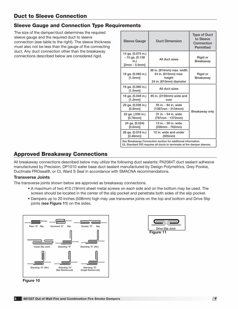
Figure 10
Drive Slip JointFigure 11
Sleeve Gauge and Connection Type Requirements
Sleeve Gauge Duct Dimension
Type of Duct to Sleeve
Connection Permitted
14 ga. (0.075 in.) - 10 ga. (0.138
in.)[2mm - 3.5mm]
All duct sizesRigid or
Breakaway
16 ga. (0.060 in.)[1.5mm]
36 in. (914mm) max. width24 in. (610mm) max.
height24 in. (610mm) diameter
Rigid or Breakaway
16 ga. (0.060 in.)[1.5mm]
All duct sizes
Breakaway only
18 ga. (0.048 in.)[1.2mm]
85 in. (2159mm) wide and over
20 ga. (0.036 in.)[0.9mm]
55 in. - 84 in. wide(1397mm - 2134mm)
22 ga. (.030 in.)[0.76mm]
31 in. - 54 in. wide(787mm - 1372mm)
24 ga. (0.024)[0.6mm]
13 in. - 30 in. wide(330mm - 762mm)
26 ga. (0.018 in.)[0.46mm]
12 in. wide and under(305mm)
See Breakaway Connection section for additional information.UL Standard 555 requires all ducts to terminate at fire damper sleeves.
The size of the damper/duct determines the required sleeve gauge and the required duct to sleeve connection (see table to the right). The sleeve thickness must also not be less than the gauge of the connecting duct. Any duct connection other than the breakaway connections described below are considered rigid.
Approved Breakaway ConnectionsAll breakaway connections described below may utilize the following duct sealants: PA2084T duct sealant adhesive manufactured by Precision, DP1010 water base duct sealant manufactured by Design Polymetrics, Grey Pookie, Ductmate PROseal®, or CL Ward S Seal in accordance with SMACNA recommendations.
Transverse JointsThe transverse joints shown below are approved as breakaway connections. • A maximum of two #10 (19mm) sheet metal screws on each side and on the bottom may be used. The
screws should be located in the center of the slip pocket and penetrate both sides of the slip pocket. • Dampers up to 20 inches (508mm) high may use transverse joints on the top and bottom and Drive Slip
joints (see Figure 11) on the sides.

461337 Out of Wall Fire and Combination Fire Smoke Dampers 7®
Round and Oval Duct Breakaway ConnectionsFactory furnished duct collars, type R and O, are also considered breakaway (see Figure 12).
Round or flat oval ducts connected to Type R or O damper collars shall be attached with #10 (19mm) sheet metal screws as follows: • Ducts up to 22 in. (558mm) wide (or dia.) and less
shall have three screws. • Ducts larger than 22 in. (558mm) wide (or dia.) up
to and including 36 in. (914mm) wide (or dia.) shall have five screws.
Fire Damper Sleeve
Neoprene or Butyl gasketbetween all angles
Flanged system angles
(Attach permanufacturer'sinstructions)
Duct
3/8 in. bolts incorners are optional
6 in. long metal cleat or 1/16 in.max. thickness plastic cleat;12 in. c-c (min. 1 per side)
Figure 13
Approved Breakaway Connections....
DuctSleeve
6 in.
Std. ClipLength
CLDuct
60 in. Duct4 Req’d.
48 in. Duct3 Req’d.
36 in. Duct3 Req’d.
24 in. Duct2 Req’d.
18 in. Duct &Smaller1 Req’d.
Clip Spacing
Typical TDC/TDF joint
6 in. 6 in.
9 in.
7 in.7 in.
5 in. 5 in.
5 in.5 in.
Figure 15
Duct EndFlange
Corner Piece
3/8 in. bolt (optional)
Figure 16
Proprietary Flange System Breakaway Connections(TDC by Lockformer, TDF by Engle)TDC and TDF systems are approved as breakaway connections when installed as described in the TDC or TDF addendum to the SMACNA Duct Construction. Standard 6 in. (152mm) metal clip may be used with spacing as shown in diagram (see Figure 14 & 15). 33⁄8 in. (9.5mm) metal bolts and nuts may be used to fasten together corner pieces (see Figure 16).
DuctSleeve
6 in.
Std. ClipLength
CLDuct
60 in. Duct4 Req’d.
48 in. Duct3 Req’d.
36 in. Duct3 Req’d.
24 in. Duct2 Req’d.
18 in. Duct &Smaller1 Req’d.
Clip Spacing
Typical TDC/TDF joint
6 in. 6 in.
9 in.
7 in.7 in.
5 in. 5 in.
5 in.5 in.
Figure 14
Wall or Floor
Sleeve
Duct Damper
Type B
Wall or Floor
Sleeve
Duct Damper
Type R, O
Type R and Ofactory furnishedduct collars qualifyas breakawayconnections.
Figure 12: Type R and O Transition
Manufactured Flanged System Breakaway ConnectionsFlanged connection systems manufactured by Ductmate, Durodyne, Ward, Nexus, Radiant T-35m, and MEZ are approved as breakaway connections when installed as illustrated (see Figure 13).

461337 Out of Wall Fire and Combination Fire Smoke Dampers 8®
Actuator and Temperature Response Device Connections
Actuator ConnectionsElectrical and/or pneumatic connections to damper actuators should be made in accordance with wiring and piping diagrams developed in compliance with applicable codes, ordinances and regulations (see Electrical Guidelines).
Temperature Response Device ConnectionsRRL - The RRL (resettable link device) incorporates a single thermostat. When the thermostat temperature is reached the sensor interrupts power to the actuator and the actuator's spring return mechanism causes the damper to close. Refer to Figure 17 for wiring of the RRL thermostat.OCI - The OCI (open or closed indicator) option contains two single pole single throw switches used to indicate the damper blade position. The switches provide a positive open and closed signal and can be used in conjunction with remote indicator lights. Refer to Figure 18 for wiring of the OCI option.RRL /OCI - The RRL/OCI performs the function of an RRL and OCI (see description above). Refer to Figure 19 for wiring of the RRL/OCI option.TOR - The TOR (temperature override device) option incorporates two thermostats with fixed settings (usually 165°F [74°C] and 350°F [177°C]). The primary sensor (the sensor with the lower temperature setting) can be bypassed by an external contact closure allowing the damper to reopen until the secondary temperature is reached (the sensor with the higher temperature setting). See Figure 20.
Figure 17: RRL Wiring
Figure 18: OCI
The TOR assembly contains two single pole single throw switches used to indicate damper blade position. The switches provide a positive open and closed signal and can be used in conjunction with remote indicator lights. See Figure 20 for wiring of the TOR thermostats and indicator switches.If either the TOR or the RRL is ordered with a pneumatic actuator, an EP switch is required with an appropriate electric power circuit to allow the electric thermostat to control the pneumatic actuator.
Ratings (Figure 17, 18, 19, & 20)Integral Switch Type: Single Pole, double throwElectrical Capacity: 10 Amps, 1/3 hp, 120 or 240 Vac 1/2 Amp, 125 Vdc; 1/4 Amp 250 Vdc 5 Amps, 120 Vac “L” (lamp load) 1.0 Amps, 24 Vac 1.5 Amps, 24 VdcTemperature Limit: 165° F (standard primary sensor) 212° F (optional primary sensor) 250° F (secondary sensor )* 350º F (secondary sensor)* * based on actuator temperature rating
Figure 19: RRL/OCI
Figure 20: TOR

461337 Out of Wall Fire and Combination Fire Smoke Dampers 9®
Damper MaintenanceDampers do not typically require maintenance as long as they are kept dry and clean. If cleaning is necessary, use mild detergents or solvents. If lubrication is desired for components such as axle bearings, jackshaft bearings and jamb seals, do not use oil-based lubricants or any other lubricants that attract contaminants such as dust.Dampers and their actuator(s) must be maintained, cycled, and tested a minimum in accordance with: • The latest editions of NFPA 80, 90A, 92, 101, 105, UL864, AMCA 503-03 and local codes. • Actuator manufacturer recommendations.
Damper TroubleshootingThe following is a possible cause and correction list for common concerns with the dampers.
Symptom Possible Cause Corrective Action
Damper does not fully open and/or close
Frame is 'racked' causing blades to bind on jamb seals
Adjust frame such that it is square and plumb
Actuator linkage loose Close damper, disconnect power, adjust and tighten linkage
Defective motor Replace
Screws in damper linkage Damper installed too far into wall. Move out to line as designated on damper label
Contaminants on damper Clean with a non-oil based solvent (see Damper Maintenance)
RRL or TOR sensor tripped
Heat Push reset button located on backside of RRL or TOR
Damper does not operate
No power supplied to the actuator Add power supply

461337 Out of Wall Fire and Combination Fire Smoke Dampers 10®
Notes

461337 Out of Wall Fire and Combination Fire Smoke Dampers 11®
Notes

Notes
461337 • OFSD, ODFD, OFD Rev. 20 December 2017 Copyright 2017 © Greenheck Fan Corporation
As a result of our commitment to continuous improvement, Greenheck reserves the right to change specifications without notice.Specific Greenheck product warranties can be located on greenheck.com within the product area tabs and listed in the Library under Warranties.
®
Phone: (715) 359-6171 • Fax: (715) 355-2399 • E-mail: [email protected] • Website: www.greenheck.com
Our Commitment