Embed Size (px)
Citation preview
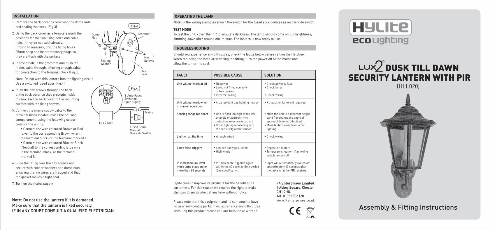
Assembly & Fitting Instructions
(HLL020)
Note: in the wiring examples shown the switch for the fused spur doubles as an override switch.
TEST MODETo test the unit, cover the PIR to simulate darkness. The lamp should come on full brightness,dimming down after around one minute. The lantern is now ready to use.
Should you experience any difficulties, check the faults below before calling the Helpline.When replacing the lamp or servicing the fitting, turn the power off at the mains andallow the lantern to cool.
Hylite tries to improve its products for the benefit of its customers. For this reason we reserve the right to make changes to any product at any time without notice.
Please note that this equipment and its components have no user serviceable parts. If you experience any difficulties installing this product please call our helpline or write to:
F4 Enterprises Limited7 Abbey Square, ChesterCH1 2HU.Tel: 01352 736120www.f4enterprises.co.uk
OPERATING THE LAMP
TROUBLESHOOTING
• No power • Lamp not fitted correctly or has broken • Incorrect wiring
• Area too light e.g. lighting nearby
• Unit is fixed too high or too low, or angle of approach into detection areas are incorrect• Other lighting interfering with the sensitivity of the sensor
• Wrongly wired
• Lantern badly positioned• High winds
• PIR has been triggered again within the 60 seconds time period (See specification)
• Check power & fuse • Check lamp
• Check wiring
• Re-position lantern if required
• Move the unit to a different height band / or change the angle of approach (see introduction)• Move lantern away from other lighting
• Check wiring
• Reposition lantern• Temporary situation. If annoying switch lantern off
• Light will automatically switch off approximately 60 seconds after the last signal the PIR receives
Unit will not work at all
Unit will not work when in normal operation
Sensing range too short
Light on all the time
Lamp false triggers
In increased Lux level mode lamp stays on for more than 60 seconds
FAULT POSSIBLE CAUSE SOLUTION
1. Remove the back cover by removing the dome nuts and sealing washers (Fig.3).
2. Using the back cover as a template mark the positions for the two fixing holes and cable entry hole, if they do not exist already. If fixing to masonry, drill the fixing holes 25mm deep and insert masonry plugs so they are flush with the surface.
3. Pierce a hole in the grommet and push the mains cable through, allowing enough cable for connection to the terminal block (Fig. 3)
Note: Do not wire this lantern into the lighting circuit. Use a switched fused spur (Fig.4).
4. Push the hex screws through the back of the back cover so they protrude inside the box. Fix the back cover to the mounting surface with the fixing screws.
5. Connect the mains supply cable to the terminal block located inside the housing compartment, using the following colour code for the wiring. • Connect the wire coloured Brown or Red (Live) to the corresponding Brown wire in the terminal block, or the terminal marked L. • Connect the wire coloured Blue or Black (Neutral) to the corresponding Blue wire in the terminal block, or the terminal marked N.
6. Slide the fitting over the hex screws and secure with rubber washers and dome nuts, ensuring that no wires are trapped and that the gasket makes a tight seal.
7. Turn on the mains supply.
Note: Do not use the lantern if it is damaged. Make sure that the lantern is fixed securely.IF IN ANY DOUBT CONSULT A QUALIFIED ELECTRICIAN.
Fig.3
Sealing Washer
Hex Screws
Back Cover
DomeNut
Grommet
3-Amp FusedSwitchedSpur Supply
Lux 2 UnitFused Spur/ManualOverride Switch
L N
Mains
INSTALLATION
Fig.4
SECURITY LANTERN WITH PIRDUSK TILL DAWNLUX2
©

PLEASE FOLLOW THESE INSTRUCTIONS CAREFULLY BEFORE ATTEMPTING TO INSTALL AND OPERATE THIS LIGHT.It is advisable to keep these instructions in a safe place for future reference. If a contractor installs this lantern, the contractor should ensure that the customer retains a copy of these instructions.
THIS PRODUCT MUST BE INSTALLED BY A QUALIFIED ELECTRICIAN.
ENSURE ELECTRICITY IS SWITCHED OFF AT THE MAINS BEFORE INSTALLING OR MAINTAINING THIS LANTERN.
THIS FITTING CONFORMS TO UK SAFETY STANDARDS AND MUST BE INSTALLED IN ACCORDANCE WITH CURRENT IEEE WIRING REGULATIONS AND BUILDING REGULATIONS (PART P).
ALL ELECTRICAL EQUIPMENT AND APPLIANCES MUST BE CHECKED TO ENSURE THEY ARE SAFE BEFORE USING.
POWER SUPPLY LEADS, PLUGS AND ALL ELECTRICAL CONNECTIONS MUST BE REGULARLY CHECKED TO ENSURE THEY ARE NOT LOOSE, WORN OR DAMAGED AND CIRCUITS ARE WELL INSULATED.
WORN OR DAMAGED LEADS, PLUGS OR CONNECTIONS SHOULD NOT BE USED AND SHOULD IMMEDIATELY BE REPLACED OR REPAIRED BY A QUALIFIED ELECTRICIAN.
THE RISK OF ELECTRIC SHOCK SHOULD BE MINIMIZED BY THE INSTALLATION OF APPROPRIATE SAFETY DEVICES INCLUDING THE INCORPORATION OF AN RCCB (RESIDUAL CURRENT CIRCUIT BREAKER) INTO THE MAIN DISTRIBUTION BOARD.
DO NOT WIRE THIS LANTERN DIRECTLY INTO THE LIGHTING CIRCUIT. USE A SWITCHED FUSED SPUR (FIG.4). CABLES SHOULD ALWAYS BE PROTECTED AGAINST SHORT CIRCUIT AND OVERLOAD.
ENSURE THE VOLTAGE MARKED ON THE PRODUCT IS THE SAME AS THE ELECTRICAL POWER SUPPLY TO BE USED.
DO NOT PULL POWER CABLE ONCE INSTALLED AND DO NOT PULL POWER PLUGS FROM SOCKETS BY THE POWER CABLE.
DO NOT INSTALL THE LIGHT: - WHERE IT IS LIKELY TO BE KNOCKED OR HIT. - IN HOT OR HUMID CONDITIONS SUCH AS BATHROOMS, SHOWER ROOMS OR SAUNAS. - NEAR AN EXHAUST OUTLET E.G. BOILER FLUE, DRYER OUTLET.
THE LIGHT CAN BECOME HOT DURING USE. THEREFORE DO NOT TOUCH THE LIGHT WHEN OPERATING, AND ALLOW TO COOL BEFORE TOUCHING.
THE LIGHT SHOULD NOT BE USED NEAR FLAMMABLE OR COMBUSTIBLE MATERIALS (SUCH AS WOOD, CLOTH, PAPER) OR NEAR FLAMMABLE, COMBUSTIBLE OR EXPLOSIVE LIQUIDS, SOLIDS, GASES OR EQUIPMENT.
THE MAINS POWER SUPPLY MUST BE DISCONNECTED BEFORE SERVICING OR PERFORMING ANY MAINTENANCE.
THE LIGHT SHOULD BE MAINTAINED IN GOOD CONDITION WITH REPAIR ONLY BE UNDERTAKEN BY A QUALIFIED ELECTRICIAN.
REPAIRS SHOULD ONLY BE CARRIED OUT USING GENUINE PARTS. NON-AUTHORIZED PARTS MAY BE DANGEROUS AND WILL INVALIDATE THE WARRANTY.
NOTE: For new installations, check for any electrical cables or pipework (gas/water) in the vicinity of the intended mounting point for the product, before proceeding with the installation.
1 x LUX 2 Dusk till Dawn Security Lantern with PIR1 x 18W CFL lamp1 x Fixing kit (2 x wall plugs, 2 x No.8 masonry screws)
1 x Instruction manual (please keep safe for future reference)
• Electric / hand-held drill• No.8 masonry drill bit• Electricians screwdriver• Small hammer• Adjustable spanner• Wire cutters
This product is suitable for wall mounting.
Voltage: 230 ACLamp: 18W GX24 Q2. Only PLD or PLTWeather resistance: IP44Electrical safety: BS-EN 60598 (revelant clauses)PIR angle of detection: 90º approx.PIR max. detection range: Up to 5m depending on weather conditions and mounting locationMounting height: 1.4 to 1.9 metresOperation: Operation in hours of darkness onlyTime on (increased lux level): 60 seconds from last trigger
• The lanterns built-in PIR detects in a fan-shaped arc of approximately 90° for a distance of up to 5 metres, depending upon weather conditions and mounting height.
• For the PIR to work at its best, the lantern should be located so the PIR is crossed, not approached head-on. The examples in Fig.1 illustrate this.
• The lantern should also be located away from trees, hot ventilator ducts, street lighting and traffic, which may interfere with its operation.
• In most cases, for the sensor to work at its best, the lantern should be fixed approximately 1.4 - 1.9m from the ground.
NOTE: When the lantern is positioned directly facing a person walking straight towards it, the detection range can be as little as 1.5metres. We therefore recommend that the lantern be positioned to the side of an entrance.
90º
5m
Longer detection range
Shortdetection range
Viewed from above
Fig.1
PARTS INCLUDED
TOOLS REQUIRED
SPECIFICATION
CHOOSING A MOUNTING LOCATION
IMPORTANT SAFETY INSTRUCTIONS
IMPORTANT INSTALLATION INSTRUCTIONS
IMPORTANT OPERATION AND MAINTENANCE INSTRUCTIONS
• The lantern sensor is controlled by a built-in photocell so that it operates only between dusk and dawn.
• At dusk, the sensor will switch on the light automatically, increasing the lux level to full brightness then, after around 1 minute, luxing down to dim-down mode (where it consumes only around 6W of power).
• The lantern will stay in a dim down mode, until the PIR is triggered when the LUX 2 lantern will lux up to full brightness. It will stay at full brightness, if not triggered again, for 60 seconds. If triggered further, the light will stay on for 60 seconds from the last trigger.
• The lantern will then return to the dim down mode, and switch off automatically at dawn.
1. Attach the lantern base to the lantern head using the plastic threaded ring (Fig.2).
2. Fit the sprung metal lampholder cover over the lampholder and push in place to secure.
3. Fit the lamp in the lamp holder (ensuring the type and wattage are as indicated in these instructions and on the lamp holder).
4. Slide the plastic panels securely into position on the lantern head.
5. Secure the lantern finial into the canopy and fit the canopy to the lantern head with the screws provided.
OPERATION
ASSEMBLING THE LANTERN
Fig.2
Lantern Head
PIR Sensor
LampHolder
Finial
PlasticPanels
Washer
Screw
LanternBase