Embed Size (px)
Citation preview

Smart Connect Single Loop Touch Screen Panel
Doc: GLT-229-7-1 1
Issue: 3 Date: 12/05/2017
ONE LOOP TOUCH SCREEN ANALOGUE ADDRESSABLE
FIRE ALARM PANEL
INSTALLATION MANUAL
Smart Connect Single Loop Touch Screen Panel
Doc: GLT-229-7-1 2
Issue: 3 Date: 12/05/2017
MANUAL SECTIONS 1- SAFETY INFORMATION ................................................................................................................................... 3
2- PANEL SPECIFICATION .................................................................................................................................... 6
3-INTRODUCTION TO THE SMART CONNECT PANEL ........................................................................................ 10
4 - DESIGNING THE SYSTEM ............................................................................................................................. 19
5 - INSTALLING THE PANEL ............................................................................................................................... 24
6 - INSTALLING THE DEVICES……………………………………………………………………………………………………………………...28
7 - PANEL SET UP .............................................................................................................................................. 41
8 - PROGRAMMING .......................................................................................................................................... 48
9 - DISABLEMENTS ............................................................................................................................................ 64
10 - TEST MODE ................................................................................................................................................ 68
11 - NETWORKING ............................................................................................................................................ 71
12 - FAULT FINDING .......................................................................................................................................... 75
13 - STANDBY BATTERY REQUIREMENTS ......................................................................................................... 83
14 - CE INFORMATION ...................................................................................................................................... 87
15 - DOCUMENT MODIFICATION HISTORY....................................................................................................... 88

Smart Connect Single Loop Touch Screen Panel
Doc: GLT-229-7-1 3
Issue: 3 Date: 12/05/2017
1- SAFETY INFORMATION
1.1 INSTALLATION INFORMATION ...................................................................................................................... 4
1.2 SAFETY PRECAUTIONS DURING NORMAL OPERATION OF PANEL ............................................................... 4
1.3 BATTERY INFORMATION ............................................................................................................................... 4
1.4 PRODUCT DISPOSAL AT THE END OF ITS WORKING LIFE ............................................................................. 4
1.5 USING THIS MANUAL .................................................................................................................................... 5
1.6 FIRE ALARM SYSTEMS CODE OF PRACTICE ................................................................................................... 5
1.7 EQUIPMENT WARRANTY .............................................................................................................................. 5

Smart Connect Single Loop Touch Screen Panel
Doc: GLT-229-7-1 4
Issue: 3 Date: 12/05/2017
WARNING: Read this section completely before commencing installation.
1.1 INSTALLATION INFORMATION THIS FIRE ALARM CONTROL PANEL IS CLASS1 EQUIPMENT AND MUST BE EARTHED. This equipment must be installed and maintained by a qualified and technically experienced person. This C.I.E. must be wired to a fused spur rated at 3A. It must NOT be connected via a removable plug, or be connected through an RCD device. It is designed for indoor use only. Prior to commencing installation of the control panel, ensure that adequate precautions are taken to prevent damage to the sensitive electronic components on the display board and the control board due to electrostatic discharge. You should discharge any static electricity you may have accumulated by touching a convenient earthed object such as an unpainted copper radiator pipe. You should repeat the process at regular intervals during the installation process, especially if you are required to walk over carpets. The panel must be located in a clean, dry position, which is not subject to excessive shock or vibration and at least 2 metres away from pager systems or any other radio transmitting equipment. The operating temperature range is 0ºC to 40ºC; maximum humidity is 95%. HANDLING THE PCBS If the PCBs are to be removed to ease fitting the enclosure and cables, care must be taken to avoid damage by static. The best method is to wear an earth strap, but touching any earth point (e.g. building plumbing) will help to discharge any static. Always handle PCBs by their sides and avoid touching the legs of any components. Keep the PCBs away from damp dirty areas, e.g. in a small cardboard box.
1.2 SAFETY PRECAUTIONS DURING NORMAL OPERATION OF PANEL NOTE: When the Smart Connect panel is operating normally, i.e. not being tended by service personnel, the panel enclosure must be kept closed, secured by the supplied hex screws. The hex key to open the cover MUST be removed and ONLY held by the responsible person and / or the service personnel. It must under NO CIRCUMSTANCES be held by the user.
1.3 BATTERY INFORMATION This C.I.E. uses 2 x 12V Sealed Lead Acid (SLA) batteries with capacities between 3Ah and 7Ah. CAUTION: RISK OF EXPLOSION IF BATTERY IS REPLACED BY AN INCORRECT TYPE. DISPOSE OF USED BATTERIES ACCORDING TO BATTERY MANUFACTURERS INSTRUCTIONS. IMPORTANT NOTES ON BATTERIES: DANGER: Batteries are electrically live at all times. NEVER short circuit the battery terminals. WARNING: Batteries are often heavy. Each 17Ah battery weighs 6.1kg. Take great care when lifting and transporting batteries. DANGER: Do NOT attempt to remove the battery lid or tamper with the internal workings of the battery. Electrolyte is a highly corrosive substance, and presents significant danger to yourself and to anything else it touches. In case of accidental skin or eye contact, flush the affected area with plenty of clean, fresh water and seek immediate medical attention. Valve Regulated Lead Acid (VRLA) batteries are “low maintenance”, requiring no electrolyte top-up or measurement of specific gravity.
1.4 PRODUCT DISPOSAL AT THE END OF ITS WORKING LIFE Like all electronic equipment, at the end of its working life this unit should not be disposed of in a refuse bin. It should be taken to a local reprocessing site as per the guidelines of the WEEE directive, for correct disposal.

Smart Connect Single Loop Touch Screen Panel
Doc: GLT-229-7-1 5
Issue: 3 Date: 12/05/2017
1.5 USING THIS MANUAL This manual explains, in a step-by-step manner, the procedure for the installation of the Smart Connect Fire Alarm Control Panel. This Installation Manual must not be left accessible to the User.
1.6 FIRE ALARM SYSTEMS CODE OF PRACTICE This manual is not designed to teach Fire Alarm System design. It is assumed that the System has been designed by a competent person, and that the installer has an understanding of Fire Alarm System components and their use. We strongly recommend consultation with a suitably qualified, competent person regarding the design of the Fire Alarm System. The System must be commissioned and serviced in accordance with our instructions and the relevant National Standards. Contact the Fire Officer concerned with the property at an early stage in case he has any special requirements. If in doubt, read the latest edition of BS 5839-1 “Fire Detection and Alarm Systems for buildings (Code of Practice for System Design, Installation, commissioning and maintenance)” available from the BSI, or at your local reference library.
1.7 EQUIPMENT WARRANTY If this equipment is not fitted and commissioned according to our guidelines, and the relevant National Standards, by an approved and competent person or organisation, the warranty may become void.

Smart Connect Single Loop Touch Screen Panel
Doc: GLT-229-7-1 6
Issue: 3 Date: 12/05/2017
2- PANEL SPECIFICATION
2.1 FUNCTIONS REQUIRED BY EUROPEAN STANDARD EN 54 PART 2 ............................................................... 7
2.2 EXPLANATION OF ACCESS LEVELS ................................................................................................................ 7
2.3 PANEL SPECIFICATIONS - ENCLOSURE .......................................................................................................... 8
2.4 PANEL SPECIFICATIONS - ELECTRICAL .......................................................................................................... 8
2.5 FUSE SPECIFICATIONS - Power Supply Controller PCB ................................................................................. 9
2.6 FUSE SPECIFICATIONS - CIE PCB ................................................................................................................... 9

Smart Connect Single Loop Touch Screen Panel
Doc: GLT-229-7-1 7
Issue: 3 Date: 12/05/2017
2.1 FUNCTIONS REQUIRED BY EUROPEAN STANDARD EN 54 PART 2 The Smart Connect fire alarm control panel provides the following mandatory and optional functions as prescribed by the European standard EN 54 Part 2. (a) Mandatory Functions The mandatory functions and corresponding indications provided by this panel are:
fire alarm condition
fault warning condition
disablement condition
quiescent condition (when the CIE is powered by a power supply conforming to EN 54-4 and no other functional condition is indicated)
(b) Optional Functions (Options with Requirements) The options with requirements provided by this panel are:
Clause 7.8 - output to fire alarm devices (i.e. sounders)
Clause 7.11 - delays to outputs
Clause 7.12 – Dependencies on More than one alarm signal (Type C)
Clause 8.3 - fault signals from points
Clause 9.5 - disablement of addressable points
Clause 10 – test Condition
(c) Other Functions outside EN54 USB Port (For PC configuration) RS484 Network / Repeater connection TCP/IP (Ethernet) connection (Remote access) NB the terms 'device' and 'point' are used interchangeably throughout this manual.
2.2 EXPLANATION OF ACCESS LEVELS The Smart Connect System has the following access levels.
ACCESS LEVEL ACCESSED BY ACCESS METHOD FUNCTIONS ACCESSED
1 General public Default state View Panel Override delay (if used)
2a Responsible person Enter user access code (default 0001)
Start sounders stop sounders Silence buzzer Reset panel Access User Menu
2b Responsible person Enter user access code (default 0001), and press Menu Access Icon
Enable / disable sections of system Test Mode View Zones / Points View event log Turn off delay
3a Installer / Engineer Enter Engineer Password (Default 9999), and press Menu Access Icon
Configure loops Assign zones Assign Text to each point Modify Alarm Operation Programming Configure network (if fitted) System Diagnostics (LED blink / loop Autocheck) Change passwords Configure TCP/IP Port
3b Installer / Engineer Open Enclosure Connect wiring during Install Battery check during Maintenance Update Cause & Effect programming via USB
4 Authorised Service Engineer Open Enclosure & PC S/W Update Panel Firmware, Add new language
Care should be taken to ensure that the access method for each level is only available to suitably qualified personnel.

Smart Connect Single Loop Touch Screen Panel
Doc: GLT-229-7-1 8
Issue: 3 Date: 12/05/2017
2.3 PANEL SPECIFICATIONS - ENCLOSURE DESCRIPTION VALUE
ENCLOSURE SIZE (L x W x D mm) 370 X 311 X 113 mm
TOP CABLE ENTRIES 15
BOTTOM CABLE ENTRIES 0
2.4 PANEL SPECIFICATIONS - ELECTRICAL ELECTRICAL DESCRIPTION VALUE MAINS VOLTAGE 230 V AC + 10% / - 15%
BATTERY VOLTAGE 2 x 12V SLA (27.6V DC @ 20 C) (3Ah – 7Ah)
POWER SUPPLY NON-INTEGRAL (SWITCH MODE) DC OUTPUT: Vmax = 31V ,Vmin = 19.5V I max A: 4.1 A Ripple & Noise: <= 0.6V
CIE DC INPUT VOLTAGE Vmax = 31.5V, Vmin = 19.5V
CHARGER VOLTAGE 27.3V
Monitored Inputs (x2) End-of-Line Resistance: 4k7ohm 0.25W Trigger value: 2k7 ohm
CONVENTIONAL SOUNDER OUTPUT (x2) I max: 100mA Quiescent voltage: -5 to -9V DC Active voltage: 18 to 28V DC End-of-Line Resistance: 4k7 ohm 0.25W
FIRE RELAY OUTPUT (x1) (C,NO,NC) Contact rating: 230V AC @ 1A
FAULT RELAY OUTPUT (x1) Normally Energised (C,NO,NC) Contact rating: 230V AC @ 1A
AUX 28V 100mA
LOOP VOLTAGE 35V Nominal (Vmax 39 V DC Vmin 24 V DC)
MAXIMUM LOOP CURRENT 500 mA
NUMBER OF LOOPS 1
MAXIMUM NUMBER OF ZONES 254 Zones
MAXIMUM LOOP CAPACITY 254 Addresses
MAXIMUM LOOP LENGTH 2 km
MAXIMUM LOOP RESISTANCE 44 ohm (22 ohms + to +, 22 ohms – to -)
MAXIMUM LOOP CAPACITANCE 500 nF
MAXIMUM LOOP BAUD RATE 1024 Bits Per Second
MAXIMUM NETWORK SIZE 16 nodes
MAXIMUM DISTANCE BETWEEN NODES 1 km with screened Data cable
LCD DISPLAY 4.3” Resistive touch screen. 480 x 272 pixel resolution
LED INDICATION Fire Zones 1 – 16 Fault / Disable / Test Zones 1 - 16 Power Common Fire Sounder Delay On General Disablement Controls active System Fault Common Fault Sounder Fault / Disablement General Test Sounder Active
KEY ENTRY Start Sounders Stop Sounders Silence Buzzer Reset (All other controls via touch screen)
ENVIRONMENTAL DATA Temperature: -5 to 40 C Relative Humidity: 95% Non-Condensing will withstand vibrations between 5 & 150 Hz
ENCLOSURE RATING IP 30
OTHER PORTS USB RS485 for network TCP/IP Micro SD card (for future use)
EN 54-2 Optional Functions with Requirements 7.8, 7.11,7.12, 8.3, 9.5, 10

Smart Connect Single Loop Touch Screen Panel
Doc: GLT-229-7-1 9
Issue: 3 Date: 12/05/2017
2.5 FUSE SPECIFICATIONS - Power Supply Controller PCB
Fuse Label Rating Description
A_Fuse 1A PSU Output – Channel A (USED TO POWER PANEL)
B_Fuse 1A PSU Output – Channel B (SPARE)
Battery Fuse 5A Battery fuse
2.6 FUSE SPECIFICATIONS - CIE PCB The Smart Connect CIE PCB has no User serviceable fuses. It uses resettable fuses throughout

Smart Connect Single Loop Touch Screen Panel
Doc: GLT-229-7-1 10
Issue: 3 Date: 12/05/2017
3-INTRODUCTION TO THE SMART CONNECT PANEL
3.1 ABOUT THE SMART CONNECT FIRE ALARM PANEL ................................................................................... 11
3.2 PANEL INTERNAL LAYOUT .......................................................................................................................... 12
3.3 ACCESSING THE PANEL ............................................................................................................................... 13
3.4 NAVIGATING THE PANEL MENUS ............................................................................................................... 14
3.5 CONTROLS .................................................................................................................................................. 15
3.6 INDICATING DIFFERENT PANEL STATES ...................................................................................................... 16
3.6.1 The Quiescent Condition .............................................................................................................. 16
3.6.2 The Alarm Condition ..................................................................................................................... 16
3.6.3 The Fault Condition ...................................................................................................................... 16
3.6.4. Disablement ................................................................................................................................ 17
3.6.5 Test Mode ..................................................................................................................................... 18
3.6.6 Multiple Conditions ...................................................................................................................... 18
Smart Connect Single Loop Touch Screen Panel
Doc: GLT-229-7-1 11
Issue: 3 Date: 12/05/2017
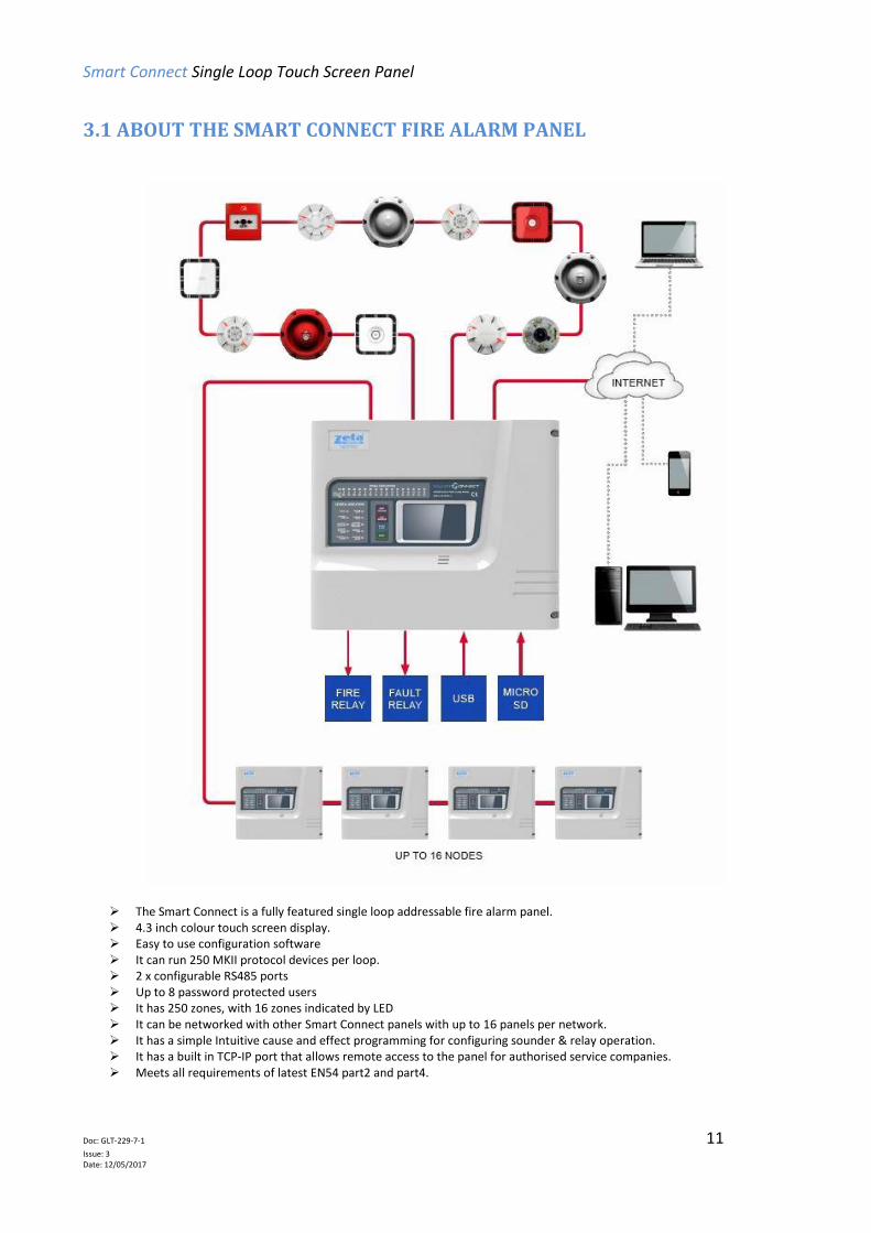
3.1 ABOUT THE SMART CONNECT FIRE ALARM PANEL
The Smart Connect is a fully featured single loop addressable fire alarm panel. 4.3 inch colour touch screen display. Easy to use configuration software It can run 250 MKII protocol devices per loop. 2 x configurable RS485 ports Up to 8 password protected users It has 250 zones, with 16 zones indicated by LED It can be networked with other Smart Connect panels with up to 16 panels per network. It has a simple Intuitive cause and effect programming for configuring sounder & relay operation. It has a built in TCP-IP port that allows remote access to the panel for authorised service companies. Meets all requirements of latest EN54 part2 and part4.

Smart Connect Single Loop Touch Screen Panel
Doc: GLT-229-7-1 12
Issue: 3 Date: 12/05/2017
3.2 PANEL INTERNAL LAYOUT
Figure1
Figure1: Plan view of Smart Connect panel showing internal view with main PCB fitted and with main PCB removed

Smart Connect Single Loop Touch Screen Panel
Doc: GLT-229-7-1 13
Issue: 3 Date: 12/05/2017
3.3 ACCESSING THE PANEL The Smart Connect panel has 2 user access levels and one installer access level.
Basic user access (Access level 2a) Tap LCD. Select user icon. Enter user access code (Default 0001) This allows the user to have access to the main control buttons, to silence and reset the panel. It is indicated by a steady Controls Active LED, and an open padlock icon in the bottom left corner of the LCD screen.
Full user access (Access level 2b) From access level 2a press the menu access icon. This allows the user to view the user menus, to view device status, event logs etc. It is indicated by a steady Controls Active LED, and an open padlock icon in the bottom left corner of the LCD screen.
Engineer Access (Access level 3a) Tap LCD. Select Engineer icon. Enter Engineer access code (Default 9999) This allows the engineer to configure the panel, Setting zone & device text, allocating zones, entering panel cause & effect etc. It is indicated by a Flasing Controls Active LED, and an open padlock icon in the bottom left corner of the LCD screen. (The access LED flashes as a reminder that the panel is at a high access level, and should not be left unattended in this state.)
Turning off access.
If the panel is in one of the menus, press the exit menu icon in the bottom left corner. Press the padlock icon in the bottom left corner. The controls active LCD will turn off, and the padlock icon will turn off. (The panel will automatically turn off access if left unattended for aprox 5 minutes)
Smart Connect Single Loop Touch Screen Panel
Doc: GLT-229-7-1 14
Issue: 3 Date: 12/05/2017
3.4 NAVIGATING THE PANEL MENUS
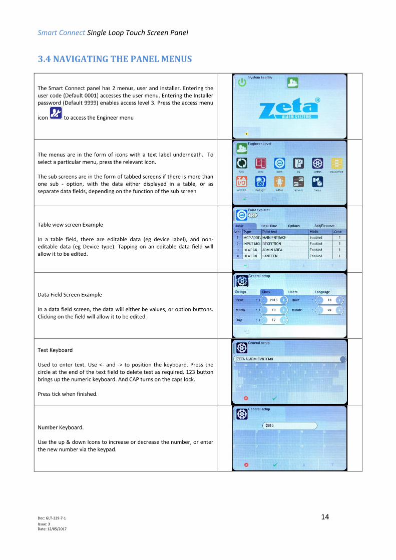
The Smart Connect panel has 2 menus, user and installer. Entering the user code (Default 0001) accesses the user menu. Entering the Installer password (Default 9999) enables access level 3. Press the access menu
icon to access the Engineer menu
The menus are in the form of icons with a text label underneath. To select a particular menu, press the relevant icon. The sub screens are in the form of tabbed screens if there is more than one sub - option, with the data either displayed in a table, or as separate data fields, depending on the function of the sub screen
Table view screen Example In a table field, there are editable data (eg device label), and non-editable data (eg Device type). Tapping on an editable data field will allow it to be edited.
Data Field Screen Example In a data field screen, the data will either be values, or option buttons. Clicking on the field will allow it to be edited.
Text Keyboard Used to enter text. Use <- and -> to position the keyboard. Press the circle at the end of the text field to delete text as required. 123 button brings up the numeric keyboard. And CAP turns on the caps lock. Press tick when finished.
Number Keyboard. Use the up & down Icons to increase or decrease the number, or enter the new number via the keypad.

Smart Connect Single Loop Touch Screen Panel
Doc: GLT-229-7-1 15
Issue: 3 Date: 12/05/2017
3.5 CONTROLS
The panel contains the following mandatory controls. They can only be operated when the user or engineer (ADMIN) password has
been entered. The CONTROLS ACTIVE LED indicates that the controls have been enabled.
This control can be used by authorised personnel to start the sounders.
This control can be used by authorised personnel to stop or silence the sounders whilst the panel is in the
fire alarm condition.
This control silences the panel’s internal buzzer which is always activated when a fire or a fault has been
detected.
After an alarm has been fully investigated and dealt with, operating this control resets the fire alarm
condition. The same control is used to reset from a fault condition.
It is good practice to stop the sounders before resetting the panel. However, pressing the RESET control whilst the sounders are still
active will silence the sounders as well as resetting the fire alarm condition.
OTHER CONTROLS
Other controls are through virtual buttons on the panel`s touch screen display. They include, amongst others, alpha and numeric
key pads, cursors for table navigation and accept & cancel buttons for system changes

Smart Connect Single Loop Touch Screen Panel
Doc: GLT-229-7-1 16
Issue: 3 Date: 12/05/2017
3.6 INDICATING DIFFERENT PANEL STATES During Normal operation the panel will be in one of the following states depending on the status of the devices connected to the panel, and user intervention. Below is a summary of the different conditions
3.6.1 The Quiescent Condition
This is the panel’s normal state. There are no faults or alarms, and the panel is running normally. This is indicated by The LCD showing System Normal, and All LEDS being off, apart from Power, and perhaps Controls Active (depending on the last user action). In the quiescent condition, the panel displays:- System Healthy. Zeta Logo
3.6.2 The Alarm Condition A fire is indicated on the Smart Connect panel by:-
COMMON FIRE RED LED & Zone alarm LED (for zones 1 to 16)
On the screen, the panel shows:-
Fire Icon Number of zones in alarm Number of devices in alarm First & last zones in alarm Details of alarms in chronological order (showing device type, Zone number & label, Device address & label) Scroll arrows for displaying further events
3.6.3 The Fault Condition
All faults are indicated by a flashing yellow common fault LED,
and either an additional fault LED, or an LCD message.
Faults can be divided into 2 types, “Device Faults” and “General
Faults”. Device Faults are any fault associated with a particular
device address on the loop. They usually report Address & zone
information as well as a description of the fault.
General Faults are everything else, e.g. sounder circuits, power
supply, earth faults etc. Any fault on the panel will flash the
common fault LED in addition to displaying details of the fault.
Smart Connect Single Loop Touch Screen Panel
Doc: GLT-229-7-1 17
Issue: 3 Date: 12/05/2017
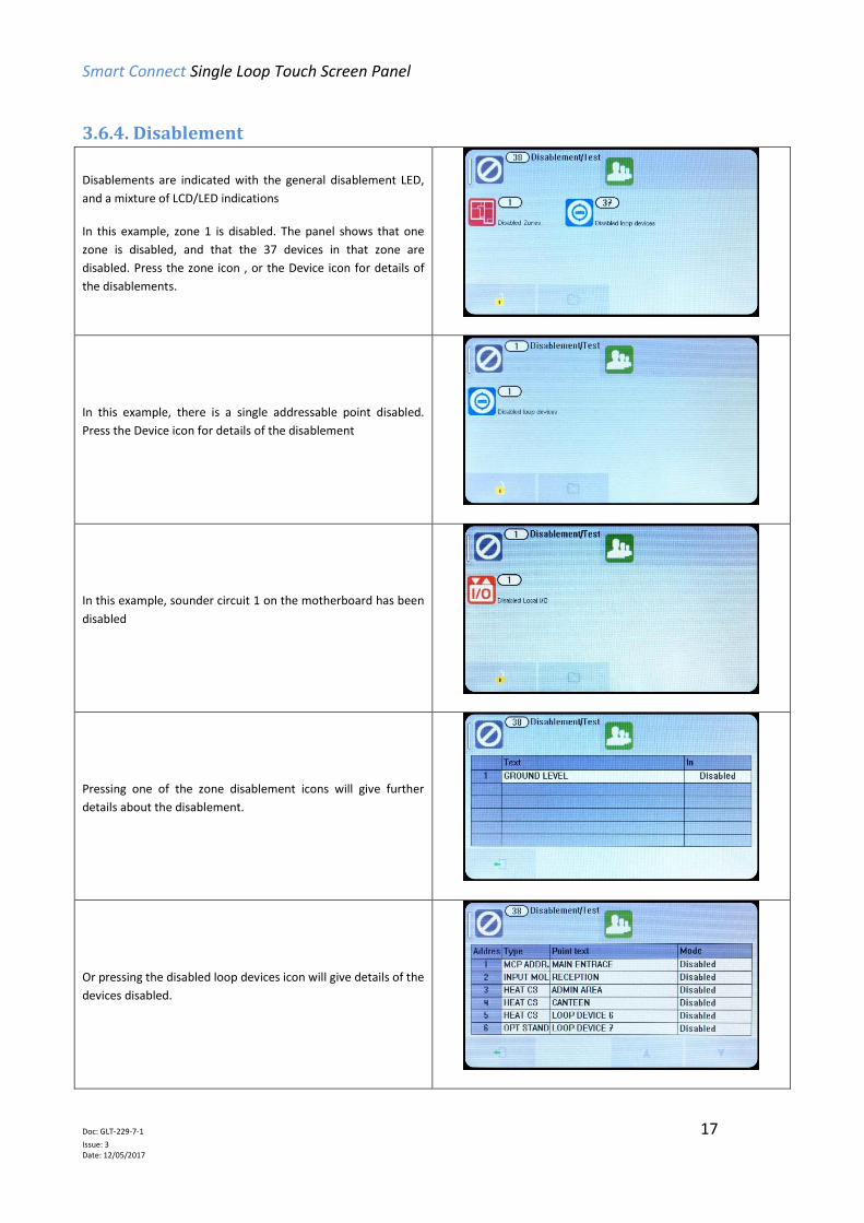
3.6.4. Disablement
Disablements are indicated with the general disablement LED,
and a mixture of LCD/LED indications
In this example, zone 1 is disabled. The panel shows that one
zone is disabled, and that the 37 devices in that zone are
disabled. Press the zone icon , or the Device icon for details of
the disablements.
In this example, there is a single addressable point disabled.
Press the Device icon for details of the disablement
In this example, sounder circuit 1 on the motherboard has been
disabled
Pressing one of the zone disablement icons will give further
details about the disablement.
Or pressing the disabled loop devices icon will give details of the
devices disabled.
Smart Connect Single Loop Touch Screen Panel
Doc: GLT-229-7-1 18
Issue: 3 Date: 12/05/2017
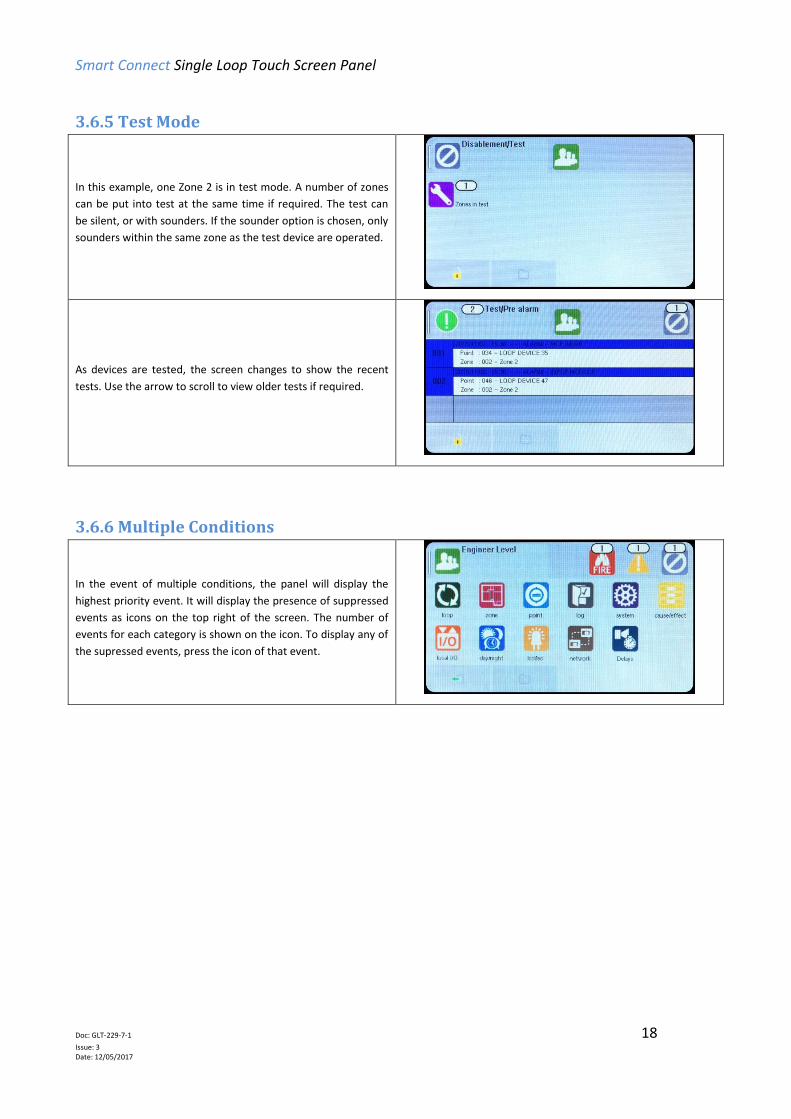
3.6.5 Test Mode
In this example, one Zone 2 is in test mode. A number of zones
can be put into test at the same time if required. The test can
be silent, or with sounders. If the sounder option is chosen, only
sounders within the same zone as the test device are operated.
As devices are tested, the screen changes to show the recent
tests. Use the arrow to scroll to view older tests if required.
3.6.6 Multiple Conditions
In the event of multiple conditions, the panel will display the
highest priority event. It will display the presence of suppressed
events as icons on the top right of the screen. The number of
events for each category is shown on the icon. To display any of
the supressed events, press the icon of that event.
Smart Connect Single Loop Touch Screen Panel
Doc: GLT-229-7-1 19
Issue: 3 Date: 12/05/2017
4 - DESIGNING THE SYSTEM 4.1 DESIGNING THE SYSTEM ............................................................................................................................. 20
4.2 RECOMMENDED CABLE TYPES AND THEIR LIMITATIONS .......................................................................... 20
4.3 LOOP CALCULATIONS ................................................................................................................................. 20
4.4 MAXIMUM LOOP CABLE LENGTH RECOMMENDATIONS ........................................................................... 21
4.5 BATTERY CALCULATIONS ............................................................................................................................ 21
4.6 CHOOSING AUDIBLE & VISIBLE WARNING DEVICES ................................................................................... 21
4.6.1 ADDRESSABLE SOUNDER .............................................................................................................. 21
4.6.2 ADDRESSABLE SOUNDER BASE ..................................................................................................... 21
4.6.3 PCB CONVENTIONAL SOUNDER CIRCUITS .................................................................................... 22
4.6.4 ADVANTAGES AND DISADVANTAGES OF DIFFERENT SOUNDER TYPES ....................................... 22
4.7 System Spare Capacity………………………………………………………………………………………………………………………23
Smart Connect Single Loop Touch Screen Panel
Doc: GLT-229-7-1 20
Issue: 3 Date: 12/05/2017
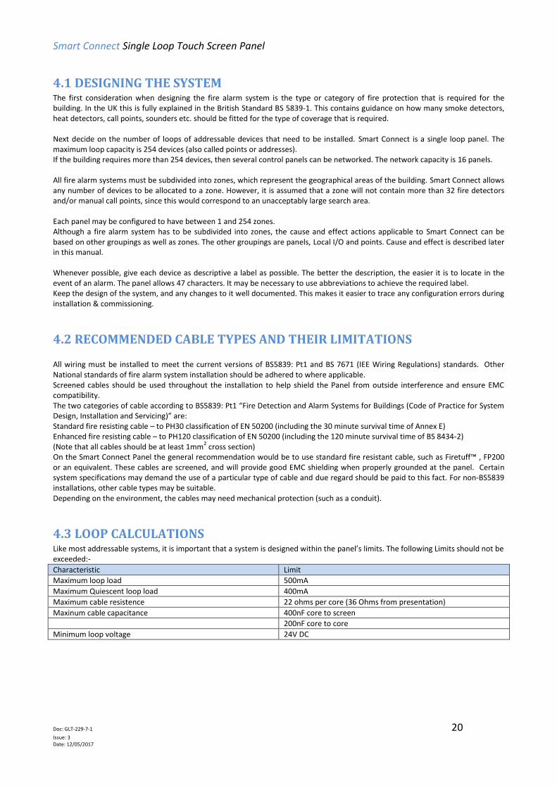
4.1 DESIGNING THE SYSTEM The first consideration when designing the fire alarm system is the type or category of fire protection that is required for the building. In the UK this is fully explained in the British Standard BS 5839-1. This contains guidance on how many smoke detectors, heat detectors, call points, sounders etc. should be fitted for the type of coverage that is required. Next decide on the number of loops of addressable devices that need to be installed. Smart Connect is a single loop panel. The maximum loop capacity is 254 devices (also called points or addresses). If the building requires more than 254 devices, then several control panels can be networked. The network capacity is 16 panels. All fire alarm systems must be subdivided into zones, which represent the geographical areas of the building. Smart Connect allows any number of devices to be allocated to a zone. However, it is assumed that a zone will not contain more than 32 fire detectors and/or manual call points, since this would correspond to an unacceptably large search area. Each panel may be configured to have between 1 and 254 zones. Although a fire alarm system has to be subdivided into zones, the cause and effect actions applicable to Smart Connect can be based on other groupings as well as zones. The other groupings are panels, Local I/O and points. Cause and effect is described later in this manual. Whenever possible, give each device as descriptive a label as possible. The better the description, the easier it is to locate in the event of an alarm. The panel allows 47 characters. It may be necessary to use abbreviations to achieve the required label. Keep the design of the system, and any changes to it well documented. This makes it easier to trace any configuration errors during installation & commissioning.
4.2 RECOMMENDED CABLE TYPES AND THEIR LIMITATIONS All wiring must be installed to meet the current versions of BS5839: Pt1 and BS 7671 (IEE Wiring Regulations) standards. Other National standards of fire alarm system installation should be adhered to where applicable. Screened cables should be used throughout the installation to help shield the Panel from outside interference and ensure EMC compatibility. The two categories of cable according to BS5839: Pt1 “Fire Detection and Alarm Systems for Buildings (Code of Practice for System Design, Installation and Servicing)” are: Standard fire resisting cable – to PH30 classification of EN 50200 (including the 30 minute survival time of Annex E) Enhanced fire resisting cable – to PH120 classification of EN 50200 (including the 120 minute survival time of BS 8434-2) (Note that all cables should be at least 1mm
2 cross section)
On the Smart Connect Panel the general recommendation would be to use standard fire resistant cable, such as Firetuff™ , FP200 or an equivalent. These cables are screened, and will provide good EMC shielding when properly grounded at the panel. Certain system specifications may demand the use of a particular type of cable and due regard should be paid to this fact. For non-BS5839 installations, other cable types may be suitable. Depending on the environment, the cables may need mechanical protection (such as a conduit).
4.3 LOOP CALCULATIONS Like most addressable systems, it is important that a system is designed within the panel’s limits. The following Limits should not be exceeded:-
Characteristic Limit
Maximum loop load 500mA
Maximum Quiescent loop load 400mA
Maximum cable resistence 22 ohms per core (36 Ohms from presentation)
Maxinum cable capacitance 400nF core to screen
200nF core to core
Minimum loop voltage 24V DC

Smart Connect Single Loop Touch Screen Panel
Doc: GLT-229-7-1 21
Issue: 3 Date: 12/05/2017
4.4 MAXIMUM LOOP CABLE LENGTH RECOMMENDATIONS With an addressable system, some care must be taken when calculating the appropriate cable gauge for the system. The main limitation is that during an alarm condition (maximum current draw), the voltage at all devices must be at least 24 Volts with at least 2.5V of superimposed data signal. The exact calculation equations are beyond the scope of this manual, because of the distributed load of the sounders on the loop, but the following table gives a rough guide for maximum cable lengths at various current loads for 3 different cable gauges.
MAXIMUM LOOP CURRENT (IN ALARM) 500 mA 400 mA 300 mA 200 mA
1mm CSA cable 500m 625m 830m 1250m
1.5mm CSA cable 750m 930m 1250m 1870m
2.5mm CSA cable 1000m 1250m 1660m 2500m
EG. A system with a maximum load of 300mA using 1.5mm cable can have a maximum loop run of 1250m end to end. When Installed the cable characteristics should meet the following parameters:-
+ve in to +ve out less than 22 ohms.
-ve in to -ve out less than 22 ohms (may need to temporarily disable isolators to measure).
+ve to –ve greater than 500k ohm.
+ve to Earth greater than 1M ohm.
-ve to Earth greater than 1M ohm.
+ve to –ve less than 50 mV pickup (on AC & DC scales).
+ve to –ve Capacitance Less than 0.5uF.
+ve to Earth Capacitance Less than 0.5uF.
-ve to Earth Capacitance Less than 0.5uF
4.5 BATTERY CALCULATIONS All systems will have a required stand by time and alarm time. The usual Standby times are 24 hours, 48 hours, or 72 hours, depending on the type of system. Generally 30 minutes of alarm time is considered sufficient. Information on calculating the required battery size can be found later in this manual. Alternatively, a battery calculation spreadsheet is available. Please contact your distributor for details.
4.6 CHOOSING AUDIBLE & VISIBLE WARNING DEVICES There are a number of options for Audible & visual Devices that can be directly or indirectly connected to the loop of a Smart Connect panel:
A maximum of 64 loop powered sounders are permitted on each loop (which can be either stand-alone sounders or sounder bases.
A maximum of 254 devices can be connected to the loop, with addresses 1 to 254 which can occur in any order. Short circuit isolators should be used to prevent losing the whole loop in the event of a single short circuit fault. They
should be fitted to each zone boundary, such that any short circuit will only affect the devices in 1 zone.
4.6.1 ADDRESSABLE SOUNDER This type of sounder takes one of the 254 addresses available on each loop. The address is set with the programming tool. It can be activated individually, or in groups related to its zone number, as determined by the cause and effect programmed.
4.6.2 ADDRESSABLE SOUNDER BASE This consists of an addressable sounder in the base of an addressable detector. The sounder and detector are set to different addresses, i.e. two devices are located at the same position on a loop but occupy two addresses. The address is set with the programming tool, or with dip switches, depending on the model used. It can be activated individually, or in groups related to its zone number, as determined by the cause and effect programmed.

Smart Connect Single Loop Touch Screen Panel
Doc: GLT-229-7-1 22
Issue: 3 Date: 12/05/2017
4.6.3 PCB CONVENTIONAL SOUNDER CIRCUITS The termination PCB has 2 conventional sounder circuit outputs, with a maximum capacity of 100 mA each. Please note that conventional sounders should be wired as shown in the diagram below: *The descriptions of sounders in this section also apply to flashers and combined sounder / flashers.
+ - -++ - -+
SND+
SND-SOUNDER SOUNDER
+ - -+
SOUNDER
+ - -+
SOUNDER
10K
End of
Line Resistor
Note: If non-polarised alarm devices (e.g. some types of old mechanical bell, or a relay) are used, then a diode will have to be placed in line with the device to enable fault monitoring. They may also need a back EMF protection diode. (symptoms: Chattering sounder relays that don’t turn off).
+ - -+
SND+
SND-BELL
10K
End of
Line Resistor+ - -+ + - -+
BELL BELL
CONNECTOR
BLOCKPOLARISING
DIODE
BACK EMF
DIODE
NC
NO
CM
RELAY
4.6.4 ADVANTAGES AND DISADVANTAGES OF DIFFERENT SOUNDER TYPES SOUNDER TYPE ADVANTAGE DISADVANTAGE
Conventional
Wide range of devices. Devices tend to be cheaper. Immediate start / stop. No quiescent current.
Needs extra cabling. All sounders on each circuit start together
Stand-Alone Addressable or Addressed Sounder Base
No extra cabling. Can be individually started. Can use any type of detector.
Tends to be more expensive. Maximum 64 per loop. Quiescent current relatively high. Uses an address.
Combined Detector sounder Can be individually started. Only uses one address space. Uses a standard detector base.
Only available as an optical detector. Not available as heat, opto-heat, dual optical etc
Addressable Sounder Circuit Controller
Wide range of devices. Devices tend to be cheaper. Can Add many sounder circuits to system. Sounder circuit can be assigned to zone.
Needs Extra Cabling. Needs External PSU. Uses device Address.
4k7
End of Line
Resistor
4k7
End of Line
Resistor
Smart Connect Single Loop Touch Screen Panel
Doc: GLT-229-7-1 23
Issue: 3 Date: 12/05/2017
4.7 System Spare Capacity The UK Fire alarm system code of Practice for Designing, Installing, Commissioning & maintaining fire alarm systems,
BS5839 recommends allowing at least 25% free capacity when designing a fire system.
This is a good precaution as it allows for:-
Changes to the system requirements before the site is finished
Additional devices identified as part of the commissioning process
Future Changes to the building layout (eg partitioning an open plan area)
If a system is designed to full capacity, any small additions might mean substantial changes (network an extra panel, or
change panel to an alternative model)

Smart Connect Single Loop Touch Screen Panel
Doc: GLT-229-7-1 24
Issue: 3 Date: 12/05/2017
5 - INSTALLING THE PANEL
5.1 MOUNTING THE FIRE ALARM CONTROL PANEL ......................................................................................... 25
5.2 LOCATING THE FIRE ALARM CONTROL PANEL ........................................................................................... 25
5.3 FIXING THE BACK BOX TO THE WALL .......................................................................................................... 25
5.4 MAINS WIRING RECOMMENDATIONS ....................................................................................................... 26
5.5 PLANNING CABLE ENTRY ............................................................................................................................ 26
5.6 CONNECTING THE MAINS POWER ............................................................................................................. 26
5.7 CONNECTING THE BATTERIES ..................................................................................................................... 27

Smart Connect Single Loop Touch Screen Panel
Doc: GLT-229-7-1 25
Issue: 3 Date: 12/05/2017
5.1 MOUNTING THE FIRE ALARM CONTROL PANEL The Smart Connect comes with many cable entry holes. If another entry hole is required, it is strongly recommended that the panel door is removed to avoid accidental damage. Also, the back plate which holds the loop cards and power supply should be removed and stored in a safe place. This would also help while fixing the back box to the wall.
5.2 LOCATING THE FIRE ALARM CONTROL PANEL The control panel should be installed in accordance with the following recommendations:- The panel should be close to the main entrance of the building, so that it can be viewed by any fire-fighting personnel entering the building.
It should be fitted to a sturdy wall that will not flex unnecessarily.
It should ideally be mounted at eye level, in order for it to be viewed without need of a ladder.
It should be installed in a dry, weatherproof place, preferably NOT in direct sunlight.
It should be easily accessible, so that the responsible person can perform their regular fire alarm checks.
5.3 FIXING THE BACK BOX TO THE WALL
Figure 1
Figure 1: Plan view inside the enclosure without PCBs. Side view for surface installation. (Dimensions: mm)
Fix the enclosure to the wall using the three mounting holes provided (2 circular holes near the bottom of the rear face and one 'keyhole' near the top of the rear face). Check the build and condition of the wall to decide a suitable screw fixing. The mounting holes are designed for No 8 roundhead or countersunk woodscrews (or similar). Remove any debris from the enclosure. Take care not to damage the FACP during installation.
Smart Connect Single Loop Touch Screen Panel
Doc: GLT-229-7-1 26
Issue: 3 Date: 12/05/2017
5.4 MAINS WIRING RECOMMENDATIONS The Mains supply to the FACP is fixed wiring, using Fire resisting 3-core cable (Between 1 mm² and 2.5mm²), fed from an isolating double pole switch fused spur, fused at 3A. IT SHOULD NOT BE CONNECTED THROUGH AN RCD. This should be secure from unauthorised operation and be marked ‘FIRE ALARM: DO NOT SWITCH OFF’. The supply must be exclusive to the Fire Panel. MAKE SURE ANY SPARE ENTRY HOLES ARE COVERED WITH THE GROMMETS PROVIDED. For information on how to connect Mains to the Panel’s Power Supply PCB, see Section 6. Also refer to rating information on the mains cover inside the FACP.
5.5 PLANNING CABLE ENTRY Fig.2 below shows the location of the cable entries to facilitate planning of wiring to be brought to the panel. The Knock-out cable entries can be easily removed by Tapping with a suitable screwdriver or chisel from outside the control panel box. Alternatively, the entry can be drilled out, using a 19mm hole cutter. Care should be taken if using a drill. Consider removing the main PCB to prevent damaging it.
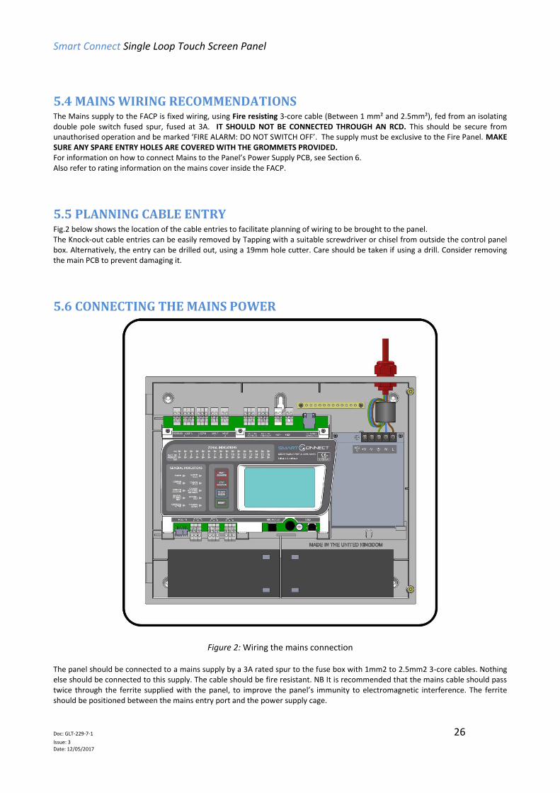
5.6 CONNECTING THE MAINS POWER
Figure 2: Wiring the mains connection
The panel should be connected to a mains supply by a 3A rated spur to the fuse box with 1mm2 to 2.5mm2 3-core cables. Nothing else should be connected to this supply. The cable should be fire resistant. NB It is recommended that the mains cable should pass twice through the ferrite supplied with the panel, to improve the panel’s immunity to electromagnetic interference. The ferrite should be positioned between the mains entry port and the power supply cage.

Smart Connect Single Loop Touch Screen Panel
Doc: GLT-229-7-1 27
Issue: 3 Date: 12/05/2017
The AC Live (L), Earth (E) and Neutral (N) connections are marked on the power supply cage. It is essential that the mains Earth cable is connected to the PSU’s Earth terminal. The incoming mains cable should be kept separate from the loop cables to help minimise mains interference. MAKE SURE ANY SPARE ENTRY HOLES THAT HAVE BEEN OPENED, BUT NOT USED ARE COVERED WITH SUITABLE GROMMETS OR BLANKING SCREWS It is advisable to apply power to the panel before connecting any devices, to check for correct operation, and to familiarise yourself with the fire alarm panels controls. If a knockout is removed, fill the hole with a suitable cable gland. If any knockout is removed, but subsequently not used, it should be covered up. The 230V AC Mains cable must be fed into the enclosure via one of the cable entries at the top right corner of the back box. (Refer to “Connecting the Mains Power” in Section 6.1).
5.7 CONNECTING THE BATTERIES
Figure 3: Battery location and connection details.
To calculate the exact requirement, use the equation in the STANDBY BATTERY REQUIREMENTS section. The two batteries are wired in series. The +ve of one battery is connected to the red battery lead. The –ve of the other battery is connected to the black battery lead. The –ve of the first battery is connected to the +ve of the second battery using the link wire supplied. Recommended Battery Types: Powersonic 12V, 7 Ah Other makes and sizes of battery may be suitable. Calculate the standby requirements to determine the most suitable size of battery

Smart Connect Single Loop Touch Screen Panel
Doc: GLT-229-7-1 28
Issue: 3 Date: 12/05/2017
6 - INSTALLING THE DEVICES
6.1 ADDRESSABLE LOOP WIRING ..................................................................................................................... 29
6.2 ADDRESSABLE LOOPS (Pre commissioning check) .................................................................................... 29
6.3 SPECIFIC DEVICE WIRING INSTRUCTIONS ................................................................................................... 30
6.3.1 CP3/AD Manual Call Point ........................................................................................................ 30
6.3.2 MKII detectors (All types) ......................................................................................................... 31
6.3.3 ZAI - MI Input Module ............................................................................................................... 32
6.3.4 ZAIO – MI Input/output Module .............................................................................................. 32
6.3.5 ZASC – MI Sounder Control Module ....................................................................................... 32
6.3.6 ZAZM – MI Conventional Zone Module .................................................................................. 33
6.3.7 Xtratone Sounder/Sounder Flasher ..................................................................................... 33
6.3.8 Sandwich Sounder ..................................................................................................................... 34
6.3.9 Remote LED Indicator................................................................................................................ 34
6.4 SETTING THE DEVICE ADDRESS (DETECTORS, CALL POINTS, SOUNDERS & INTERFACE UNITS)................. 36
6.4.1 SOFT ADDRESSING ........................................................................................................................ 36
6.4.2 DIP SWITCH ADDRESSING ............................................................................................................. 36
6.4.3 DIP SWITCH ADDRESS SETTINGS - FULL TABLE ............................................................................ 37
6.5 FIRE RELAY (VOLTAGE FREE CHANGEOVER CONTACTS) ............................................................................. 39
6.6 FAULT RELAY (VOLTAGE FREE CHANGEOVER CONTACTS) ......................................................................... 39
6.7 AUXILIARY DC OUTPUT ............................................................................................................................... 39
6.8 FIELD DEVICE TERMINATION ...................................................................................................................... 40
Smart Connect Single Loop Touch Screen Panel
Doc: GLT-229-7-1 29
Issue: 3 Date: 12/05/2017
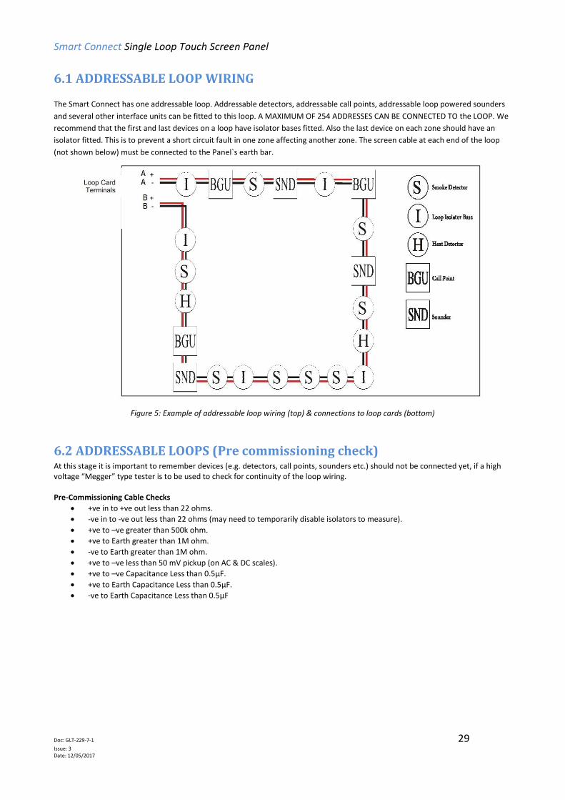
6.1 ADDRESSABLE LOOP WIRING The Smart Connect has one addressable loop. Addressable detectors, addressable call points, addressable loop powered sounders
and several other interface units can be fitted to this loop. A MAXIMUM OF 254 ADDRESSES CAN BE CONNECTED TO the LOOP. We
recommend that the first and last devices on a loop have isolator bases fitted. Also the last device on each zone should have an
isolator fitted. This is to prevent a short circuit fault in one zone affecting another zone. The screen cable at each end of the loop
(not shown below) must be connected to the Panel`s earth bar.
Figure 5: Example of addressable loop wiring (top) & connections to loop cards (bottom)
6.2 ADDRESSABLE LOOPS (Pre commissioning check) At this stage it is important to remember devices (e.g. detectors, call points, sounders etc.) should not be connected yet, if a high voltage “Megger” type tester is to be used to check for continuity of the loop wiring. Pre-Commissioning Cable Checks
+ve in to +ve out less than 22 ohms.
-ve in to -ve out less than 22 ohms (may need to temporarily disable isolators to measure).
+ve to –ve greater than 500k ohm.
+ve to Earth greater than 1M ohm.
-ve to Earth greater than 1M ohm.
+ve to –ve less than 50 mV pickup (on AC & DC scales).
+ve to –ve Capacitance Less than 0.5µF.
+ve to Earth Capacitance Less than 0.5µF.
-ve to Earth Capacitance Less than 0.5µF

Smart Connect Single Loop Touch Screen Panel
Doc: GLT-229-7-1 30
Issue: 3 Date: 12/05/2017
6.3 SPECIFIC DEVICE WIRING INSTRUCTIONS
6.3.1 CP3/AD Manual Call Point
The CP3/AD call point has a built in isolator which can be wired in circuit or not used. This is done by means of not wiring to the negative out terminal on the call point. The following terminals are used for connecting the call point.
2 x Negative in terminals (note if you only connect to the negative in terminals then the isolator is bypassed)
1 x Positive in terminal
1 x Positive out terminal
1 x Negative out terminal (note if used puts the isolator in circuit)
1 x Earth terminal used to connect the cable screen
Led Indicator: OFF = Quiescent YELLOW = Isolating RED = Fire
Protocol setting
jumper link must
be removed for
MKII protocol
Negative out terminal used when
isolator is required

Smart Connect Single Loop Touch Screen Panel
Doc: GLT-229-7-1 31
Issue: 3 Date: 12/05/2017
6.3.2 MKII detectors (All types)
Base Connection
The connection for the detectors bases is made as follows: Terminal L1IN is –ve (Blue) Terminal L2 is +ve (Brown) These are the only two connections required.
Deep Base MKII-CB/D
Common Base MKII-CB

Smart Connect Single Loop Touch Screen Panel
Doc: GLT-229-7-1 32
Issue: 3 Date: 12/05/2017
6.3.3 ZAI - MI Input Module
The end of line resistor value is 20KΩ and the trigger resistor value is 1kΩ.
6.3.4 ZAIO – MI Input/output Module
The end of line resistor value is 20KΩ and the trigger resistor value is 1KΩ.
6.3.5 ZASC – MI Sounder Control Module
The ZASC requires an external 24vdc power supply (as shown in the above diagram). The EOL for the sounder circuit is 4K7 Ω. When using the ZASC make sure the PSU being used has a fault output relay, so that in the event of a power supply fault it is reported to the control panel. Note: All Power Supplies used on fire alarm systems MUST comply with EN54 part 4
Smart Connect Single Loop Touch Screen Panel
Doc: GLT-229-7-1 33
Issue: 3 Date: 12/05/2017
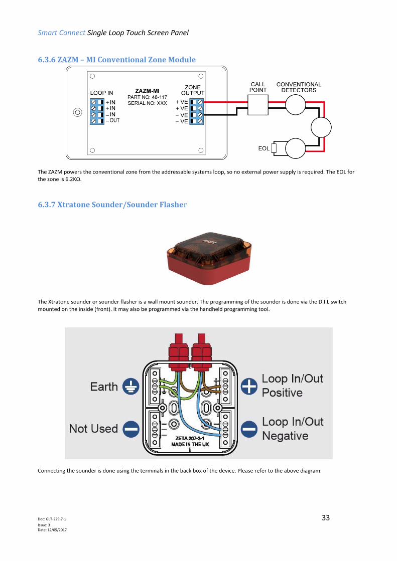
6.3.6 ZAZM – MI Conventional Zone Module
The ZAZM powers the conventional zone from the addressable systems loop, so no external power supply is required. The EOL for the zone is 6.2KΩ.
6.3.7 Xtratone Sounder/Sounder Flasher
The Xtratone sounder or sounder flasher is a wall mount sounder. The programming of the sounder is done via the D.I.L switch mounted on the inside (front). It may also be programmed via the handheld programming tool.
Connecting the sounder is done using the terminals in the back box of the device. Please refer to the above diagram.
Smart Connect Single Loop Touch Screen Panel
Doc: GLT-229-7-1 34
Issue: 3 Date: 12/05/2017
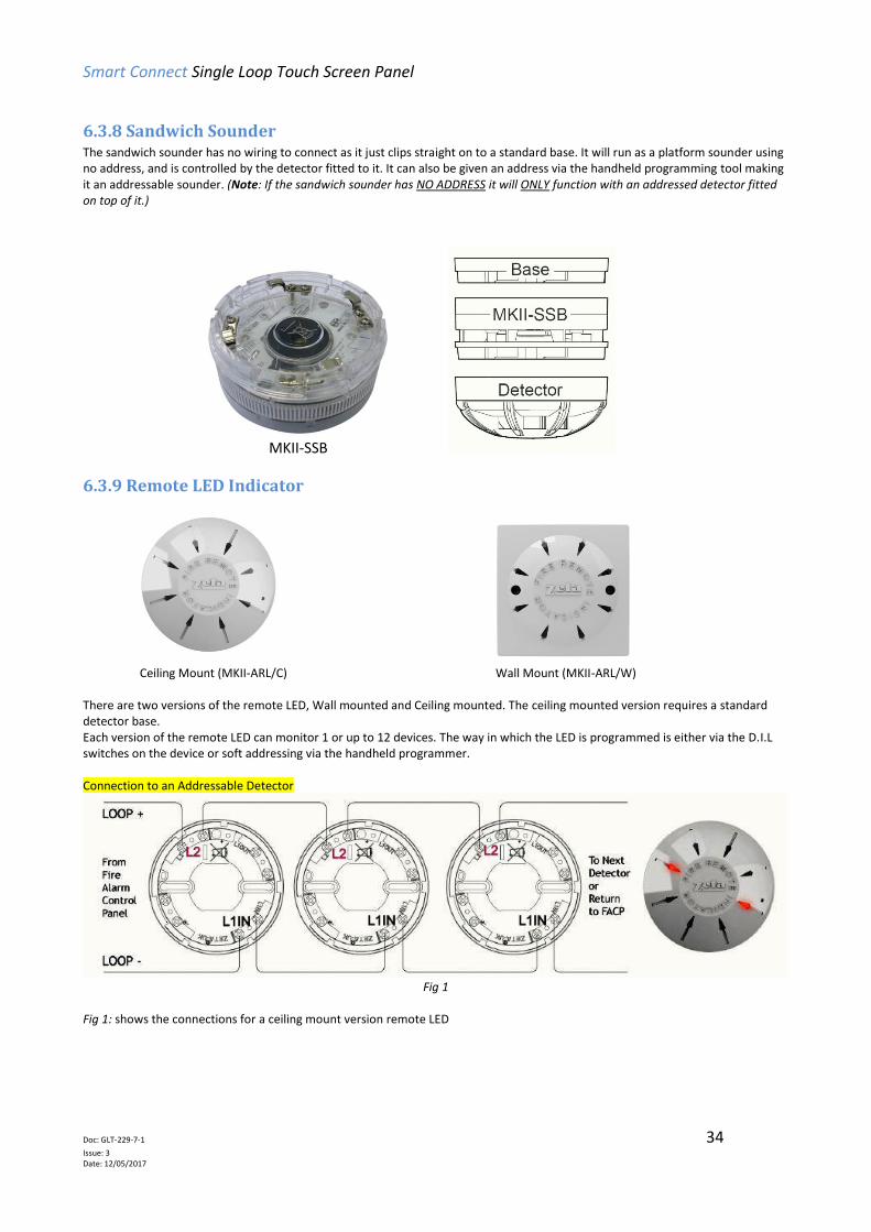
6.3.8 Sandwich Sounder The sandwich sounder has no wiring to connect as it just clips straight on to a standard base. It will run as a platform sounder using no address, and is controlled by the detector fitted to it. It can also be given an address via the handheld programming tool making it an addressable sounder. (Note: If the sandwich sounder has NO ADDRESS it will ONLY function with an addressed detector fitted on top of it.)
MKII-SSB
6.3.9 Remote LED Indicator
Ceiling Mount (MKII-ARL/C) Wall Mount (MKII-ARL/W) There are two versions of the remote LED, Wall mounted and Ceiling mounted. The ceiling mounted version requires a standard detector base. Each version of the remote LED can monitor 1 or up to 12 devices. The way in which the LED is programmed is either via the D.I.L switches on the device or soft addressing via the handheld programmer. Connection to an Addressable Detector
Fig 1
Fig 1: shows the connections for a ceiling mount version remote LED

Smart Connect Single Loop Touch Screen Panel
Doc: GLT-229-7-1 35
Issue: 3 Date: 12/05/2017
Connection to an Addressable Detector
Fig 2
Fig 2: shows the connections for a wall mount version remote LED
Smart Connect Single Loop Touch Screen Panel
Doc: GLT-229-7-1 36
Issue: 3 Date: 12/05/2017
6.4 SETTING THE DEVICE ADDRESS (DETECTORS, CALL POINTS, SOUNDERS
& INTERFACE UNITS)
Note that the devices do not need to be addressed sequentially along the loop. Technically they can be addressed in
any sequence. But addressing them sequentially will help in fault finding, should there be a problem with the loop
wiring.
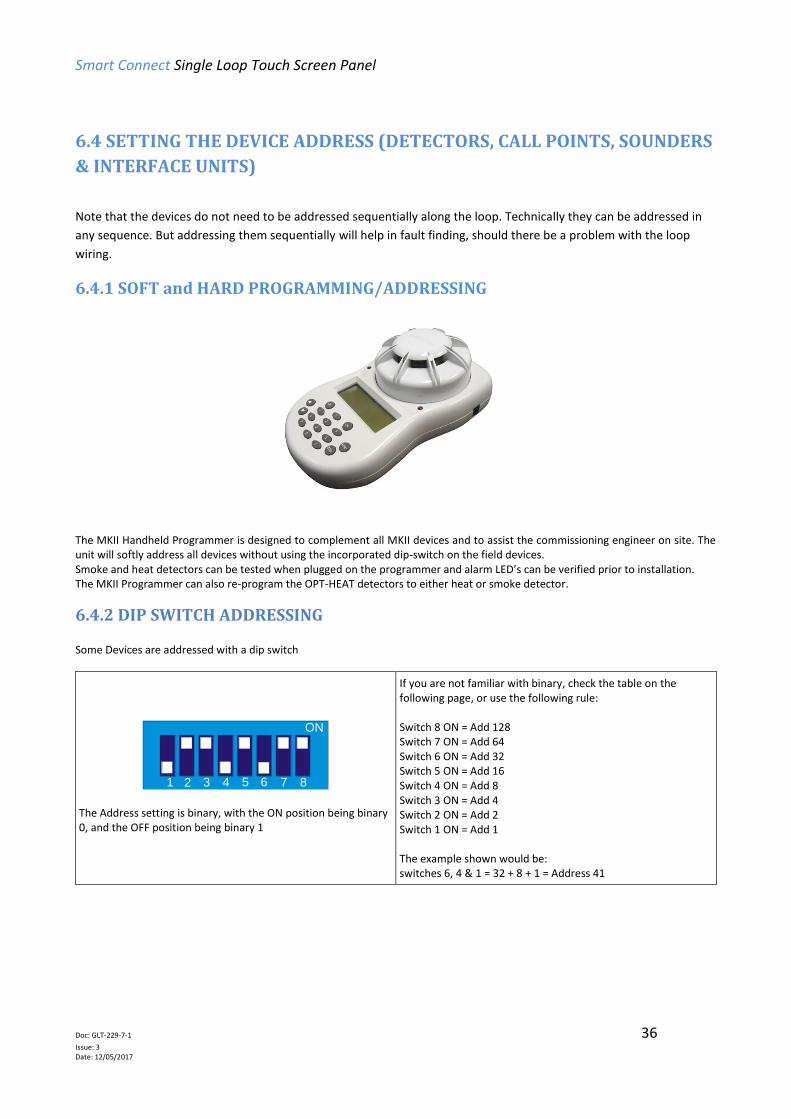
6.4.1 SOFT and HARD PROGRAMMING/ADDRESSING
The MKII Handheld Programmer is designed to complement all MKII devices and to assist the commissioning engineer on site. The unit will softly address all devices without using the incorporated dip-switch on the field devices. Smoke and heat detectors can be tested when plugged on the programmer and alarm LED’s can be verified prior to installation. The MKII Programmer can also re-program the OPT-HEAT detectors to either heat or smoke detector.
6.4.2 DIP SWITCH ADDRESSING Some Devices are addressed with a dip switch
1 765432 8
ON
The Address setting is binary, with the ON position being binary 0, and the OFF position being binary 1
If you are not familiar with binary, check the table on the following page, or use the following rule: Switch 8 ON = Add 128 Switch 7 ON = Add 64 Switch 6 ON = Add 32 Switch 5 ON = Add 16 Switch 4 ON = Add 8 Switch 3 ON = Add 4 Switch 2 ON = Add 2 Switch 1 ON = Add 1 The example shown would be: switches 6, 4 & 1 = 32 + 8 + 1 = Address 41

Smart Connect Single Loop Touch Screen Panel
Doc: GLT-229-7-1 37
Issue: 3 Date: 12/05/2017
6.4.3 DIP SWITCH ADDRESS SETTINGS - FULL TABLE
ADDRESS SWITCHES
ADDRESS SWITCHES
ADDRESS SWITCHES
1 2 3 4 5 6 7 8 1 2 3 4 5 6 7 8 1 2 3 4 5 6 7 8
0 = N O T U S E D 43 = OFF OFF ON OFF ON OFF ON ON 86 = ON OFF OFF ON OFF ON OFF ON
1 = OFF ON ON ON ON ON ON ON 44 = ON ON OFF OFF ON OFF ON ON 87 = OFF OFF OFF ON OFF ON OFF ON
2 = ON OFF ON ON ON ON ON ON 45 = OFF ON OFF OFF ON OFF ON ON 88 = ON ON ON OFF OFF ON OFF ON
3 = OFF OFF ON ON ON ON ON ON 46 = ON OFF OFF OFF ON OFF ON ON 89 = OFF ON ON OFF OFF ON OFF ON
4 = ON ON OFF ON ON ON ON ON 47 = OFF OFF OFF OFF ON OFF ON ON 90 = ON OFF ON OFF OFF ON OFF ON
5 = OFF ON OFF ON ON ON ON ON 48 = ON ON ON ON OFF OFF ON ON 91 = OFF OFF ON OFF OFF ON OFF ON
6 = ON OFF OFF ON ON ON ON ON 49 = OFF ON ON ON OFF OFF ON ON 92 = ON ON OFF OFF OFF ON OFF ON
7 = OFF OFF OFF ON ON ON ON ON 50 = ON OFF ON ON OFF OFF ON ON 93 = OFF ON OFF OFF OFF ON OFF ON
8 = ON ON ON OFF ON ON ON ON 51 = OFF OFF ON ON OFF OFF ON ON 94 = ON OFF OFF OFF OFF ON OFF ON
9 = OFF ON ON OFF ON ON ON ON 52 = ON ON OFF ON OFF OFF ON ON 95 = OFF OFF OFF OFF OFF ON OFF ON
10 = ON OFF ON OFF ON ON ON ON 53 = OFF ON OFF ON OFF OFF ON ON 96 = ON ON ON ON ON OFF OFF ON
11 = OFF OFF ON OFF ON ON ON ON 54 = ON OFF OFF ON OFF OFF ON ON 97 = OFF ON ON ON ON OFF OFF ON
12 = ON ON OFF OFF ON ON ON ON 55 = OFF OFF OFF ON OFF OFF ON ON 98 = ON OFF ON ON ON OFF OFF ON
13 = OFF ON OFF OFF ON ON ON ON 56 = ON ON ON OFF OFF OFF ON ON 99 = OFF OFF ON ON ON OFF OFF ON
14 = ON OFF OFF OFF ON ON ON ON 57 = OFF ON ON OFF OFF OFF ON ON 100 = ON ON OFF ON ON OFF OFF ON
15 = OFF OFF OFF OFF ON ON ON ON 58 = ON OFF ON OFF OFF OFF ON ON 101 = OFF ON OFF ON ON OFF OFF ON
16 = ON ON ON ON OFF ON ON ON 59 = OFF OFF ON OFF OFF OFF ON ON 102 = ON OFF OFF ON ON OFF OFF ON
17 = OFF ON ON ON OFF ON ON ON 60 = ON ON OFF OFF OFF OFF ON ON 103 = OFF OFF OFF ON ON OFF OFF ON
18 = ON OFF ON ON OFF ON ON ON 61 = OFF ON OFF OFF OFF OFF ON ON 104 = ON ON ON OFF ON OFF OFF ON
19 = OFF OFF ON ON OFF ON ON ON 62 = ON OFF OFF OFF OFF OFF ON ON 105 = OFF ON ON OFF ON OFF OFF ON
20 = ON ON OFF ON OFF ON ON ON 63 = OFF OFF OFF OFF OFF OFF ON ON 106 = ON OFF ON OFF ON OFF OFF ON
21 = OFF ON OFF ON OFF ON ON ON 64 = ON ON ON ON ON ON OFF ON 107 = OFF OFF ON OFF ON OFF OFF ON
22 = ON OFF OFF ON OFF ON ON ON 65 = OFF ON ON ON ON ON OFF ON 108 = ON ON OFF OFF ON OFF OFF ON
23 = OFF OFF OFF ON OFF ON ON ON 66 = ON OFF ON ON ON ON OFF ON 109 = OFF ON OFF OFF ON OFF OFF ON
24 = ON ON ON OFF OFF ON ON ON 67 = OFF OFF ON ON ON ON OFF ON 110 = ON OFF OFF OFF ON OFF OFF ON
25 = OFF ON ON OFF OFF ON ON ON 68 = ON ON OFF ON ON ON OFF ON 111 = OFF OFF OFF OFF ON OFF OFF ON
26 = ON OFF ON OFF OFF ON ON ON 69 = OFF ON OFF ON ON ON OFF ON 112 = ON ON ON ON OFF OFF OFF ON
27 = OFF OFF ON OFF OFF ON ON ON 70 = ON OFF OFF ON ON ON OFF ON 113 = OFF ON ON ON OFF OFF OFF ON
28 = ON ON OFF OFF OFF ON ON ON 71 = OFF OFF OFF ON ON ON OFF ON 114 = ON OFF ON ON OFF OFF OFF ON
29 = OFF ON OFF OFF OFF ON ON ON 72 = ON ON ON OFF ON ON OFF ON 115 = OFF OFF ON ON OFF OFF OFF ON
30 = ON OFF OFF OFF OFF ON ON ON 73 = OFF ON ON OFF ON ON OFF ON 116 = ON ON OFF ON OFF OFF OFF ON
31 = OFF OFF OFF OFF OFF ON ON ON 74 = ON OFF ON OFF ON ON OFF ON 117 = OFF ON OFF ON OFF OFF OFF ON
32 = ON ON ON ON ON OFF ON ON 75 = OFF OFF ON OFF ON ON OFF ON 118 = ON OFF OFF ON OFF OFF OFF ON
33 = OFF ON ON ON ON OFF ON ON 76 = ON ON OFF OFF ON ON OFF ON 119 = OFF OFF OFF ON OFF OFF OFF ON
34 = ON OFF ON ON ON OFF ON ON 77 = OFF ON OFF OFF ON ON OFF ON 120 = ON ON ON OFF OFF OFF OFF ON
35 = OFF OFF ON ON ON OFF ON ON 78 = ON OFF OFF OFF ON ON OFF ON 121 = OFF ON ON OFF OFF OFF OFF ON
36 = ON ON OFF ON ON OFF ON ON 79 = OFF OFF OFF OFF ON ON OFF ON 122 = ON OFF ON OFF OFF OFF OFF ON
37 = OFF ON OFF ON ON OFF ON ON 80 = ON ON ON ON OFF ON OFF ON 123 = OFF OFF ON OFF OFF OFF OFF ON
38 = ON OFF OFF ON ON OFF ON ON 81 = OFF ON ON ON OFF ON OFF ON 124 = ON ON OFF OFF OFF OFF OFF ON
39 = OFF OFF OFF ON ON OFF ON ON 82 = ON OFF ON ON OFF ON OFF ON 125 = OFF ON OFF OFF OFF OFF OFF ON
40 = ON ON ON OFF ON OFF ON ON 83 = OFF OFF ON ON OFF ON OFF ON 126 = ON OFF OFF OFF OFF OFF OFF ON
41 = OFF ON ON OFF ON OFF ON ON 84 = ON ON OFF ON OFF ON OFF ON 127 = OFF Off OFF OFF OFF OFF OFF ON
42 = ON OFF ON OFF ON OFF ON ON 85 = OFF ON OFF ON OFF ON OFF ON

Smart Connect Single Loop Touch Screen Panel
Doc: GLT-229-7-1 38
Issue: 3 Date: 12/05/2017
ADDRESS SWITCHES
ADDRESS SWITCHES
ADDRESS SWITCHES
1 2 3 4 5 6 7 8 1 2 3 4 5 6 7 8 1 2 3 4 5 6 7 8
128 = ON ON ON ON ON ON ON OFF 171 = OFF OFF ON OFF ON OFF ON OFF 214 = ON OFF OFF ON OFF ON OFF OFF
129 = OFF ON ON ON ON ON ON OFF 172 = ON ON OFF OFF ON OFF ON OFF 215 = OFF OFF OFF ON OFF ON OFF OFF
123 = ON OFF ON ON ON ON ON OFF 173 = OFF ON OFF OFF ON OFF ON OFF 216 = ON ON ON OFF OFF ON OFF OFF
131 = OFF OFF ON ON ON ON ON OFF 174 = ON OFF OFF OFF ON OFF ON OFF 217 = OFF ON ON OFF OFF ON OFF OFF
132 = ON ON OFF ON ON ON ON OFF 175 = OFF OFF OFF OFF ON OFF ON OFF 218 = ON OFF ON OFF OFF ON OFF OFF
133 = OFF ON OFF ON ON ON ON OFF 176 = ON ON ON ON OFF OFF ON OFF 219 = OFF OFF ON OFF OFF ON OFF OFF
134 = ON OFF OFF ON ON ON ON OFF 177 = OFF ON ON ON OFF OFF ON OFF 220 = ON ON OFF OFF OFF ON OFF OFF
135 = OFF OFF OFF ON ON ON ON OFF 178 = ON OFF ON ON OFF OFF ON OFF 221 = OFF ON OFF OFF OFF ON OFF OFF
136 = ON ON ON OFF ON ON ON OFF 179 = OFF OFF ON ON OFF OFF ON OFF 222 = ON OFF OFF OFF OFF ON OFF OFF
137 = OFF ON ON OFF ON ON ON OFF 180 = ON ON OFF ON OFF OFF ON OFF 223 = OFF OFF OFF OFF OFF ON OFF OFF
138 = ON OFF ON OFF ON ON ON OFF 181 = OFF ON OFF ON OFF OFF ON OFF 224 = ON ON ON ON ON OFF OFF OFF
139 = OFF OFF ON OFF ON ON ON OFF 182 = ON OFF OFF ON OFF OFF ON OFF 225 = OFF ON ON ON ON OFF OFF OFF
140 = ON ON OFF OFF ON ON ON OFF 183 = OFF OFF OFF ON OFF OFF ON OFF 226 = ON OFF ON ON ON OFF OFF OFF
141 = OFF ON OFF OFF ON ON ON OFF 184 = ON ON ON OFF OFF OFF ON OFF 227 = OFF OFF ON ON ON OFF OFF OFF
142 = ON OFF OFF OFF ON ON ON OFF 185 = OFF ON ON OFF OFF OFF ON OFF 228 = ON ON OFF ON ON OFF OFF OFF
143 = OFF OFF OFF OFF ON ON ON OFF 186 = ON OFF ON OFF OFF OFF ON OFF 229 = OFF ON OFF ON ON OFF OFF OFF
144 = ON ON ON ON OFF ON ON OFF 187 = OFF OFF ON OFF OFF OFF ON OFF 230 = ON OFF OFF ON ON OFF OFF OFF
145 = OFF ON ON ON OFF ON ON OFF 188 = ON ON OFF OFF OFF OFF ON OFF 231 = OFF OFF OFF ON ON OFF OFF OFF
146 = ON OFF ON ON OFF ON ON OFF 189 = OFF ON OFF OFF OFF OFF ON OFF 232 = ON ON ON OFF ON OFF OFF OFF
147 = OFF OFF ON ON OFF ON ON OFF 190 = ON OFF OFF OFF OFF OFF ON OFF 233 = OFF ON ON OFF ON OFF OFF OFF
248 = ON ON OFF ON OFF ON ON OFF 191 = OFF OFF OFF OFF OFF OFF ON OFF 234 = ON OFF ON OFF ON OFF OFF OFF
149 = OFF ON OFF ON OFF ON ON OFF 192 = ON ON ON ON ON ON OFF OFF 235 = OFF OFF ON OFF ON OFF OFF OFF
150 = ON OFF OFF ON OFF ON ON OFF 193 = OFF ON ON ON ON ON OFF OFF 236 = ON ON OFF OFF ON OFF OFF OFF
151 = OFF OFF OFF ON OFF ON ON OFF 194 = ON OFF ON ON ON ON OFF OFF 237 = OFF ON OFF OFF ON OFF OFF OFF
152 = ON ON ON OFF OFF ON ON OFF 195 = OFF OFF ON ON ON ON OFF OFF 238 = ON OFF OFF OFF ON OFF OFF OFF
153 = OFF ON ON OFF OFF ON ON OFF 196 = ON ON OFF ON ON ON OFF OFF 239 = OFF OFF OFF OFF ON OFF OFF OFF
154 = ON OFF ON OFF OFF ON ON OFF 197 = OFF ON OFF ON ON ON OFF OFF 240 = ON ON ON ON OFF OFF OFF OFF
155 = OFF OFF ON OFF OFF ON ON OFF 198 = ON OFF OFF ON ON ON OFF OFF 241 = OFF ON ON ON OFF OFF OFF OFF
156 = ON ON OFF OFF OFF ON ON OFF 199 = OFF OFF OFF ON ON ON OFF OFF 242 = ON OFF ON ON OFF OFF OFF OFF
157 = OFF ON OFF OFF OFF ON ON OFF 200 = ON ON ON OFF ON ON OFF OFF 243 = OFF OFF ON ON OFF OFF OFF OFF
158 = ON OFF OFF OFF OFF ON ON OFF 201 = OFF ON ON OFF ON ON OFF OFF 244 = ON ON OFF ON OFF OFF OFF OFF
159 = OFF OFF OFF OFF OFF ON ON OFF 202 = ON OFF ON OFF ON ON OFF OFF 245 = OFF ON OFF ON OFF OFF OFF OFF
160 = ON ON ON ON ON OFF ON OFF 203 = OFF OFF ON OFF ON ON OFF OFF 246 = ON OFF OFF ON OFF OFF OFF OFF
161 = OFF ON ON ON ON OFF ON OFF 204 = ON ON OFF OFF ON ON OFF OFF 247 = OFF OFF OFF ON OFF OFF OFF OFF
162 = ON OFF ON ON ON OFF ON OFF 205 = OFF ON OFF OFF ON ON OFF OFF 248 = ON ON ON OFF OFF OFF OFF OFF
163 = OFF OFF ON ON ON OFF ON OFF 206 = ON OFF OFF OFF ON ON OFF OFF 249 = OFF ON ON OFF OFF OFF OFF OFF
164 = ON ON OFF ON ON OFF ON OFF 207 = OFF OFF OFF OFF ON ON OFF OFF 250 = ON OFF ON OFF OFF OFF OFF OFF
165 = OFF ON OFF ON ON OFF ON OFF 208 = ON ON ON ON OFF ON OFF OFF 251 = N O T U S E D
166 = ON OFF OFF ON ON OFF ON OFF 209 = OFF ON ON ON OFF ON OFF OFF 252 = N O T U S E D
167 = OFF OFF OFF ON ON OFF ON OFF 210 = ON OFF ON ON OFF ON OFF OFF 253 = N O T U S E D
168 = ON ON ON OFF ON OFF ON OFF 211 = OFF OFF ON ON OFF ON OFF OFF 254 = N O T U S E D
169 = OFF ON ON OFF ON OFF ON OFF 212 = ON ON OFF ON OFF ON OFF OFF 255 = N O T U S E D
170 = ON OFF ON OFF ON OFF ON OFF 213 = OFF ON OFF ON OFF ON OFF OFF

Smart Connect Single Loop Touch Screen Panel
Doc: GLT-229-7-1 39
Issue: 3 Date: 12/05/2017
6.5 FIRE RELAY (VOLTAGE FREE CHANGEOVER CONTACTS)
Figure 3: Connections for fire relay, fault relay, conventional sounders and auxiliary DC outputs.
The fire relay changes over in any fire condition, and can be used for driving local fire fighting equipment such as sprinkler systems, magnetic door holders, air conditioning shut off, auto diallers etc. NB In the quiescent condition, there is electrical continuity between C and NC. In the fire condition, there is continuity between C and NO.
6.6 FAULT RELAY (VOLTAGE FREE CHANGEOVER CONTACTS) The fault relay is energised in the quiescent condition. This allows the relay to indicate any fault with a change of state, even in the event of total power loss. The terminals are marked for the quiescent running of the panel.
6.7 AUXILIARY DC OUTPUT This 24V DC output is provided to support low power requirements (100mA max). A separate power supply will be required for higher current applications.

Smart Connect Single Loop Touch Screen Panel
Doc: GLT-229-7-1 40
Issue: 3 Date: 12/05/2017
6.8 FIELD DEVICE TERMINATION
Figure 4: Connecting cables to the Smart Connect panel.
All cables should enter the enclosure via a cable gland, and the cable shields must be connected to the earth bar. Figure 4 illustrates how the mains cable and an addressable loop cable are connected to the panel. All other screens must be terminated at the brass earthing strip. MAKE SURE ANY UNUSED ENTRY HOLES ARE COVERED.

Smart Connect Single Loop Touch Screen Panel
Doc: GLT-229-7-1 41
Issue: 3 Date: 12/05/2017
7 - PANEL SET UP
7.1 INITIAL PANEL SET UP ................................................................................................................................. 42
7.2 SETTING TIME AND DATE ........................................................................................................................... 42
7.3 CREATING AN INSTALLATION NAME .......................................................................................................... 42
7.4 PASSWORDS ............................................................................................................................................... 43
7.5 CONFIGURING THE LOOP ........................................................................................................................... 43
7.6 ZONE LABELS............................................................................................................................................... 44
7.7 ADDRESS LABELS AND ZONING DEVICES .................................................................................................... 44
7.8 SETTING DEVICE OPTIONS .......................................................................................................................... 46

Smart Connect Single Loop Touch Screen Panel
Doc: GLT-229-7-1 42
Issue: 3 Date: 12/05/2017
7.1 INITIAL PANEL SET UP The Smart Connect panel is supplied configured ready for installation. But there are a few settings that may need to be altered.
7.2 SETTING TIME AND DATE
Press the screen. The panel prompts for a user and password. Select Engineer, and enter the Engineer (Access Level 3) password (default is 9999) Press the access menu icon, followed by the System Icon.
Select the Clock tab. Alter the time as required. Press the exit button to leave the menu.
Pressing arrow (up) or arrow (down) changes the setting by 1. To make a bigger adjustment, press the number and a keypad appears to enter the new value. Press tick to accept the value. When all values are correct, press the exit icon.
7.3 CREATING AN INSTALLATION NAME
From the installer menu, press the System Icon. Select the strings tab. Enter the Installation Name, Maintenance Company and contact number. Press the exit button to leave the menu.

Smart Connect Single Loop Touch Screen Panel
Doc: GLT-229-7-1 43
Issue: 3 Date: 12/05/2017
7.4 PASSWORDS
From the installer menu, press the System Icon. Select the USERS tab. To change a user name, press user name. To change a password, press the password. The panel prompts to enter the new password twice To delete a user, enter the password as blank. Any unused user should have the password left blank Press the exit button to leave the menu.
7.5 CONFIGURING THE LOOP
Press the screen. The panel prompts for a password. Enter the Engineer (Access Level 3) password (default is 9999) Press the loop Icon. The panel proceeds to learn the loop.
When the configuration is complete, the panel displays a summary of the devices found
To view details of the configuration, click the detail tab. This shows the device type found at each address, and also shows whether it was seen from Side A or Side B (to help locate CABLE BREAKS), and it also shows if the device seen is different to the previous database [!!] (IE has the device type been changed), or if it is the same as previously configured [=] Press the exit button to save configuration and leave the menu.

Smart Connect Single Loop Touch Screen Panel
Doc: GLT-229-7-1 44
Issue: 3 Date: 12/05/2017
7.6 ZONE LABELS The reason for subdivision of a fire alarm system was explained earlier in the manual. The Smart Connect panel has 254 zones. The first 16 zones also have LED indications. When a fire is reported, the zone number in which the fire is located is indicated on the alphanumeric display. In addition to its numerical description, a zone can be identified by a text label, e.g. 3rd floor west ext. If the installer associates a text label with each zone of a fire alarm system, this will be displayed on the LCD when a fire is detected. The maximum length of the zone text label is 46 characters.
Enter the engineer password and select the zone Icon Press on the zone text field. The panel displays it`s keyboard.
Use <- and -> to place the cursor, and to delete unwanted text. Type the zone name, and press exit when done. Repeat for all required zones.
The LCD also indicates the current mode of each zone – enabled, disabled or in test mode.
7.7 ADDRESS LABELS AND ZONING DEVICES Smart Connect is an addressable panel, i.e. it will indicate the address or location of a fire that has been detected. The address number of each point or device on the loop has already been set with the address programming tool. The installation engineer must now assign a label or location for each device, e.g. ROOM 107. A maximum of 48 characters can be used for each label. At the same time each point can be allocated to a zone.
From the ENGINEER MENU, press the Point Icon. Press the text field of the device to be edited

Smart Connect Single Loop Touch Screen Panel
Doc: GLT-229-7-1 45
Issue: 3 Date: 12/05/2017
The Panel shows the on screen keyboard. Enter the required label (up to 46 characters). Press exit to return to the device list.
Press the zone field to edit the device`s zone if required
Edit another device, or exit the device list to save the changes.
The Device list screen also shows the current mode of each device, i.e. ENABLED or DISABLED Press the MODE field of a device to toggle its state between enabled and disabled
The analogue values can be displayed by pressing the real time tab. Press the up & down arrows to scroll through the devices.
Device specific options can be set via the options tab (See following section for details). Press the Options field for the required device to set its options.

Smart Connect Single Loop Touch Screen Panel
Doc: GLT-229-7-1 46
Issue: 3 Date: 12/05/2017
The Add / Remove tab allows devices to be manually added or removed from the system. This is useful if it is not possible to perform a loop learn (eg, if a detector is to be changed to a different model, and the replacement is not available, or, if the loop is disconnected to perform maintenance / repair work)
To manually remove a device, tap the device so that it is
highlighted yellow, then press the delete icon
To manually add a device, press the add icon Select the address and device type of the item being added. Enter the point text for the device, and select which zone it will be in.
7.8 SETTING DEVICE OPTIONS Each Smart Connect device has a number of configuration settings that can be programmed at the panel. The configuration screen is accessed by selecting the device on the options tab. The options for each device are:-
Device Options
MCP (ZT-CP3/AD) Manual Call point Available options: LED flash
SMOKE DETECTOR (MK-II AOP) OPTICAL SMOKE DETECTOR Available options: LED flash Sounder R.I. Day Setting (Off/Low/Normal/High) Night Setting (Off/Low/Normal/High)

Smart Connect Single Loop Touch Screen Panel
Doc: GLT-229-7-1 47
Issue: 3 Date: 12/05/2017
OPTO/HEAT DETECTOR (MK-11 AOH) SMOKE and HEAT DETECTOR Available options: LED flash Sounder R.I. Day Setting (Off/Heat Only/Low/Normal/High) Night Setting (Off/Heat Only/Low/Normal/High)
HEAT DETECTOR: FIXED HEAT Detector (MK-II AHF) ROR HEAT DETECTOR (MK-II AHR) Available options: LED flash Sounder R.I. Day Setting (On/Off) Night Setting (On/Off)
INPUT MODULE (ZAI-MI) Addressable INPUT Module Available options: I/O EVENT
INPUT/OUTPUT MODULE (ZAIO-MI) Addressable INPUT/OUTPUT Module Available options: I/O EVENT
ZONE MONITOR MODULE (ZAZM-MI) Addressable ZONE MONITOR Module Available options: N/A
No Options Available. Settings are selected through PANEL Cause & Effect
SOUNDER CONTROL MODULE (ZASC-MI) Addressable SOUNDER CONTROL Module Available options: N/A
No Options Available. The different sound settings are selected through PANEL cause & effect.
Addressable SOUNDER (MK-II AMT/R) Addressable SOUNDER/FLASHER (MK-II AMTSF) Addressable SOUNDER (MK-II AMD/8R) Addressable SOUNDER (MK-II AXTR/R) Addressable SOUNDER/FLASHER (MK-II AXTSF) Addressable FLASHER (MK-IIAXTF)
No Options Available. The different sound and flasher settings are selected through PANEL cause & effect.

Smart Connect Single Loop Touch Screen Panel
Doc: GLT-229-7-1 48
Issue: 3 Date: 12/05/2017
8 - PROGRAMMING
8.1. CAUSE AND EFFECT.................................................................................................................................... 49
8.2 OUTPUTS AND DELAYS ............................................................................................................................... 53
8.2.1 SOUNDER DELAYS………………………………………………………………………………………………………………..……….53
8.2.1 RELAY OUT DELAYS……………………………………………………………………………………………………………..………..53
8.2.3 PROGRAMMING DELAYS…………………………………………………………………………………………………….………..53
8.2.4 SWITCHING OFF DELAYS AT ACCESS LEVEL 2………………………………………………………………………..……….54
8.3 DAY / NIGHT MODE .................................................................................................................................... 55
8.3.1 Defining Day and Night times ....................................................................................................... 55
8.3.2 Setting Day-time and Night-time delays ...................................................................................... 56
8.3.3 Setting Day-time and Night-time Detector Sensitivity ................................................................. 57
8.3.4 Indication of Day / Night Mode .................................................................................................... 58
8.4 USER Menu Summary ................................................................................................................................. 59
8.5 ENGINEER LEVEL Menu Summary .............................................................................................................. 60
8.6 CAUSE & EFFECT SETTINGS SUMMARY ...................................................................................................... 62
Smart Connect Single Loop Touch Screen Panel
Doc: GLT-229-7-1 49
Issue: 3 Date: 12/05/2017
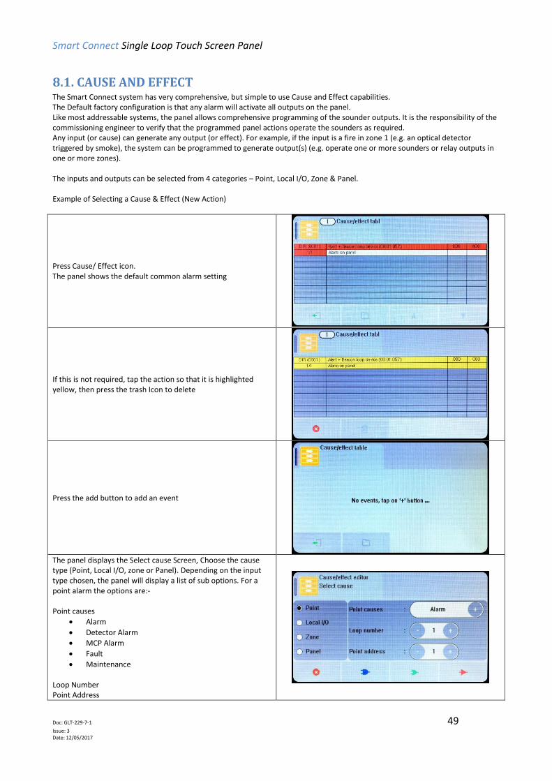
8.1. CAUSE AND EFFECT The Smart Connect system has very comprehensive, but simple to use Cause and Effect capabilities. The Default factory configuration is that any alarm will activate all outputs on the panel. Like most addressable systems, the panel allows comprehensive programming of the sounder outputs. It is the responsibility of the commissioning engineer to verify that the programmed panel actions operate the sounders as required. Any input (or cause) can generate any output (or effect). For example, if the input is a fire in zone 1 (e.g. an optical detector triggered by smoke), the system can be programmed to generate output(s) (e.g. operate one or more sounders or relay outputs in one or more zones). The inputs and outputs can be selected from 4 categories – Point, Local I/O, Zone & Panel. Example of Selecting a Cause & Effect (New Action)
Press Cause/ Effect icon. The panel shows the default common alarm setting
If this is not required, tap the action so that it is highlighted yellow, then press the trash Icon to delete
Press the add button to add an event
The panel displays the Select cause Screen, Choose the cause type (Point, Local I/O, zone or Panel). Depending on the input type chosen, the panel will display a list of sub options. For a point alarm the options are:- Point causes
Alarm
Detector Alarm
MCP Alarm
Fault
Maintenance Loop Number Point Address

Smart Connect Single Loop Touch Screen Panel
Doc: GLT-229-7-1 50
Issue: 3 Date: 12/05/2017
For a local I/O ALARM the options are:- Local I/O causes
Fault
Alarm
Tech Warning ON
Tech Warning OFF Local I/O start Local I/O end
For a Zone alarm, the options are:- Zone causes
Alarm
Detector Alarm
MCP Alarm
Fault
Maintenance
Tech Warning ON
Tech Warning OFF
Multi devices in alarm Zone Start Zone End
For a panel alarm, the options are:- Panel Address Panel causes
Alarm
Detector Alarm
MCP Alarm
Fault
Maintenance
Tech Warning ON
Tech Warning OFF
Multi devices in alarm
Multi Zones in alarm
Select whether this will be an "AND" cause, an "OR" cause, or a single "DIRECT" cause
AND OR DIRECT
An AND / OR cause will request more inputs. Select up to 8 causes. Press OUTPUT icon when finished
Smart Connect Single Loop Touch Screen Panel
Doc: GLT-229-7-1 51
Issue: 3 Date: 12/05/2017
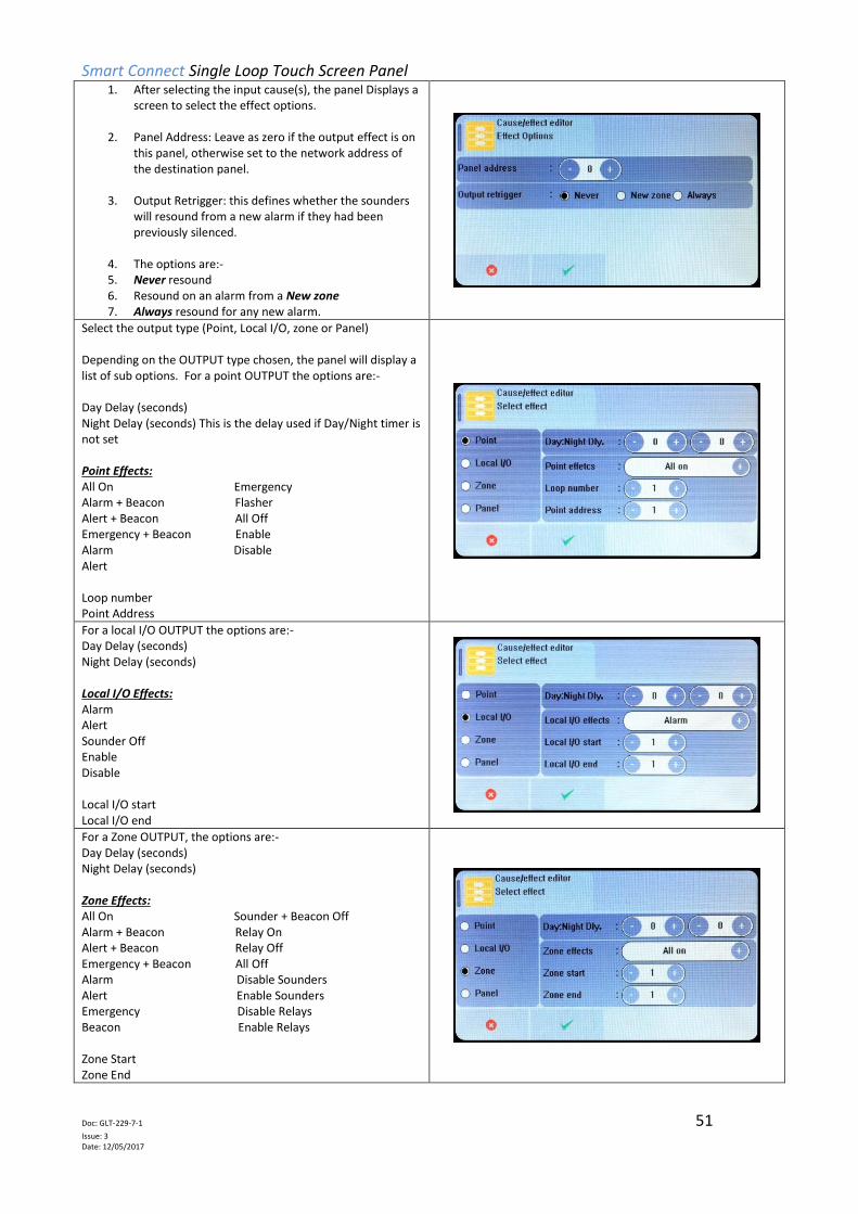
1. After selecting the input cause(s), the panel Displays a screen to select the effect options.
2. Panel Address: Leave as zero if the output effect is on
this panel, otherwise set to the network address of the destination panel.
3. Output Retrigger: this defines whether the sounders
will resound from a new alarm if they had been previously silenced.
4. The options are:- 5. Never resound 6. Resound on an alarm from a New zone 7. Always resound for any new alarm.
Select the output type (Point, Local I/O, zone or Panel) Depending on the OUTPUT type chosen, the panel will display a list of sub options. For a point OUTPUT the options are:- Day Delay (seconds) Night Delay (seconds) This is the delay used if Day/Night timer is not set Point Effects: All On Emergency Alarm + Beacon Flasher Alert + Beacon All Off Emergency + Beacon Enable Alarm Disable Alert Loop number Point Address
For a local I/O OUTPUT the options are:- Day Delay (seconds) Night Delay (seconds) Local I/O Effects: Alarm Alert Sounder Off Enable Disable Local I/O start Local I/O end
For a Zone OUTPUT, the options are:- Day Delay (seconds) Night Delay (seconds) Zone Effects: All On Sounder + Beacon Off Alarm + Beacon Relay On Alert + Beacon Relay Off Emergency + Beacon All Off Alarm Disable Sounders Alert Enable Sounders Emergency Disable Relays Beacon Enable Relays Zone Start Zone End

Smart Connect Single Loop Touch Screen Panel
Doc: GLT-229-7-1 52
Issue: 3 Date: 12/05/2017
For a panel OUTPUT, the options are:- Day Delay (seconds) Night Delay (seconds) Panel Effects: All On Sounder + Beacon Off Alarm + Beacon Relay On Alert + Beacon Relay Off Emergency + Beacon All Off Alarm Disable Sounder Alert Enable Sounder Emergency Disable Relay Beacon Enable Relay
The panel shows the Programmed cause and effect. It shows: First row Event type (DIRect, AND, OR), and entry number The programmed output. Day time delay Night time delay Second row Input number & number of inputs (for And & OR statements) Description of input
The panel displays direct actions with a red header, AND actions with a blue header, and OR actions with a green header.
It is not possible to edit a programming line. If a line needs to be altered it must be deleted (tap so that it turns yellow), then the new statement entered.

Smart Connect Single Loop Touch Screen Panel
Doc: GLT-229-7-1 53
Issue: 3 Date: 12/05/2017
8.2 OUTPUTS AND DELAYS Following the indication of a fire, the panel will activate outputs (i.e. sounders and / or relays) according to the cause and effect
rules that have been programmed. In certain circumstances, the activation of outputs may be delayed whilst the fire is being
investigated.
8.2.1 Sounder Delays If the operation of sounders has been delayed in one or more of the programmed ACTIONS, then this will be indicated by the
illumination of the DELAY ON LED (in the SOUNDER STATUS section of LEDs). When a fire has been indicated, the DELAY ON LED
remains lit until the longest sounder delay has expired.
During a fire alarm it is possible to override all the sounder delays (at any access level) by pressing the delay override icon at
the bottom of the screen, as shown.
8.2.2 Relay Output Delays Relay outputs can also be delayed via the cause and effect actions. In this case, no LED is lit to indicate a delay (since this type of
output is not mandatory).
8.2.3 Programming Delays Delays to relays and/or sounders can be programmed as part of the cause and effect programming (See previous section). If the
delay will be permanently set, the delay should be entered into the NIGHT time delay field. If the delay is only to be set at certain
times of the day, the panel should be configured for day/night mode. See following section

Smart Connect Single Loop Touch Screen Panel
Doc: GLT-229-7-1 54
Issue: 3 Date: 12/05/2017
8.2.4 Switching off Delays at Access Level 2 The panel allows the delays to be turned off by the user, as this may be required as part of the normal operation of the panel.
Enter the user menu in the usual way. (This option is also available in the Access level 3 Engineer menu)
The panel shows Delay cancelled with Off & On options. Select ON to cancel the delay, or select OFF to keep the delay. Press Exit icon and save changes as prompted.
NOTE: As the delays can be toggled on & off via the user menu. If the delay is not working as expected, check in the user menu if
the delays have been turned off.

Smart Connect Single Loop Touch Screen Panel
Doc: GLT-229-7-1 55
Issue: 3 Date: 12/05/2017
8.3 DAY / NIGHT MODE The Smart Connect panel has a day night timer that allows certain system responses to be altered at certain times of the day. It allows for different delays for the day and night times, and it also allows the sensitivity of certain detectors to be set differently for the day and night. The default state of the panel is with no day/night settings programmed. It will use the “night time” delays, and the night time detector sensitivity settings.
8.3.1 Defining Day and Night times To allow for maximum flexibility, the panel allows for more than one Day-time period each day. For example, if a site closes for a 2 hour break, the panel could be configured with 2 day-time periods eg 8:00 – 12:00 and 14:00 – 18:00. Because of this, the panel refers to each setting as a day-time slice.
Enter the engineer menu
Select the Day/Night Menu The panel shows that there are no daytime slices set.
Press the add icon to add a slice.
Select the day of the week, the start of the day slice, the end of the day slice and the operation mode: Operation Mode: MCP MCP & Heat MCP & Heat & Opto (Low) MCP & Heat & Opto (Normal) MCP & Heat & Opto (High) Per Device Set Up
Press tick to accept.
The screen shows the programmed day slice(s).
Press the add icon to add a slice, or press exit icon
if all slices are entered.

Smart Connect Single Loop Touch Screen Panel
Doc: GLT-229-7-1 56
Issue: 3 Date: 12/05/2017
When there are more than 4 slices programmed, the panel
displays up /down scroll arrows in order to view the other slices
To edit a slice, tap that slice so that it is highlighted yellow, then
press the delete icon .
Press the add icon to add a replacement slice if required.
When finished, press the exit icon . The panel will ask if you want to save the changes.
Press tick to save the changes, or press to discard.
8.3.2 Setting Day-time and Night-time delays The day and night time delays are set through the cause and effect programming.
Enter the required cause (as described in section 8.1)
When the panel asks for the output effect, enter the day time delay in the first delay field. The delay is entered in seconds. The maximum delay is 600 seconds (10 minutes). If no night time delay is needed, set the night time delay to Zero in the second field.

Smart Connect Single Loop Touch Screen Panel
Doc: GLT-229-7-1 57
Issue: 3 Date: 12/05/2017
If a night time delay is needed (for example to allow security staff to investigate, a delay can be entered into the night time delay field
Press tick to save the changes. The panel shows the cause & effect table, with the daytime delay & night time delays shown in the last 2 columns.
8.3.3 Setting Day-time and Night-time Detector Sensitivity The day and night time sensitivities are set through the Device options screen.
Go to the engineer menu, and select the point Icon
Select the Option tab. The panel displays the Options table. Press the Options field of the device to be edited. Note that only the following detectors can have their sensitivity altered:- HEAT A1S: Heat detector OPTO STANDARD: Optical Smoke detector OPTO HEAT: Optical Smoke & Heat detector
For the OPTO STANDARD: Optical Smoke detector, the sensitivity can be set to Off, Low, Normal or High. For the OPTO HEAT: Optical Smoke & Heat detector, the sensitivity can be set to Off, Heat Only, Low, Normal or High. There can be a different setting for day-time & night-time.

Smart Connect Single Loop Touch Screen Panel
Doc: GLT-229-7-1 58
Issue: 3 Date: 12/05/2017
The HEAT A1S: Heat detector and HEAT CS: Heat detector sensor can be set to Off or ON.
8.3.4 Indication of Day / Night Mode The panel indicates its current operating mode by means of a vertical bar in the top left corner of the LCD.
No Day / Night timer set. No bar in top left corner.
Day / Night timer set. Panel in Day Mode. White bar in top left corner.
Day / Night timer set. Panel in Night Mode. Black bar in top left corner.

Smart Connect Single Loop Touch Screen Panel
Doc: GLT-229-7-1 59
Issue: 3 Date: 12/05/2017
8.4 USER Menu Summary Default Password 0001 – Access level 2b
ICON TAB SCREN DESCRIPTON
Zones Zone Mode View Zone text label View / edit zone mode (Enabled/ input disabled/ output disabled/ disabled/ test/ test & sounders)
Zone Dev View Zone text label View Quantity of devices per zone
Point Basic View Address & Device type View Device text label View / Edit device mode (Enabled / disabled) View Device Zone allocation
Real Time View Address & Device type View Device text label View device Analogue Values
Log - View Event Log
Local I/O Input 1 View Input 1 zone allocation View input 1 text label View / Edit input 1 status (Enabled / disabled)
Input 2 View Input 2 zone allocation View input 2 text label View / Edit input 2 status (Enabled / disabled)
Sounder 1 View Sounder 1 zone allocation View Sounder 1 text label View / Edit Sounder 1 status (Enabled / disabled)
Sounder 2 View Sounder 2 zone allocation View Sounder 2 text label View / Edit Sounder 2 status (Enabled / disabled)
LCD / LED - Test panel LEDs , LCD & Buzzer
Delays - Toggle panel delays on or off
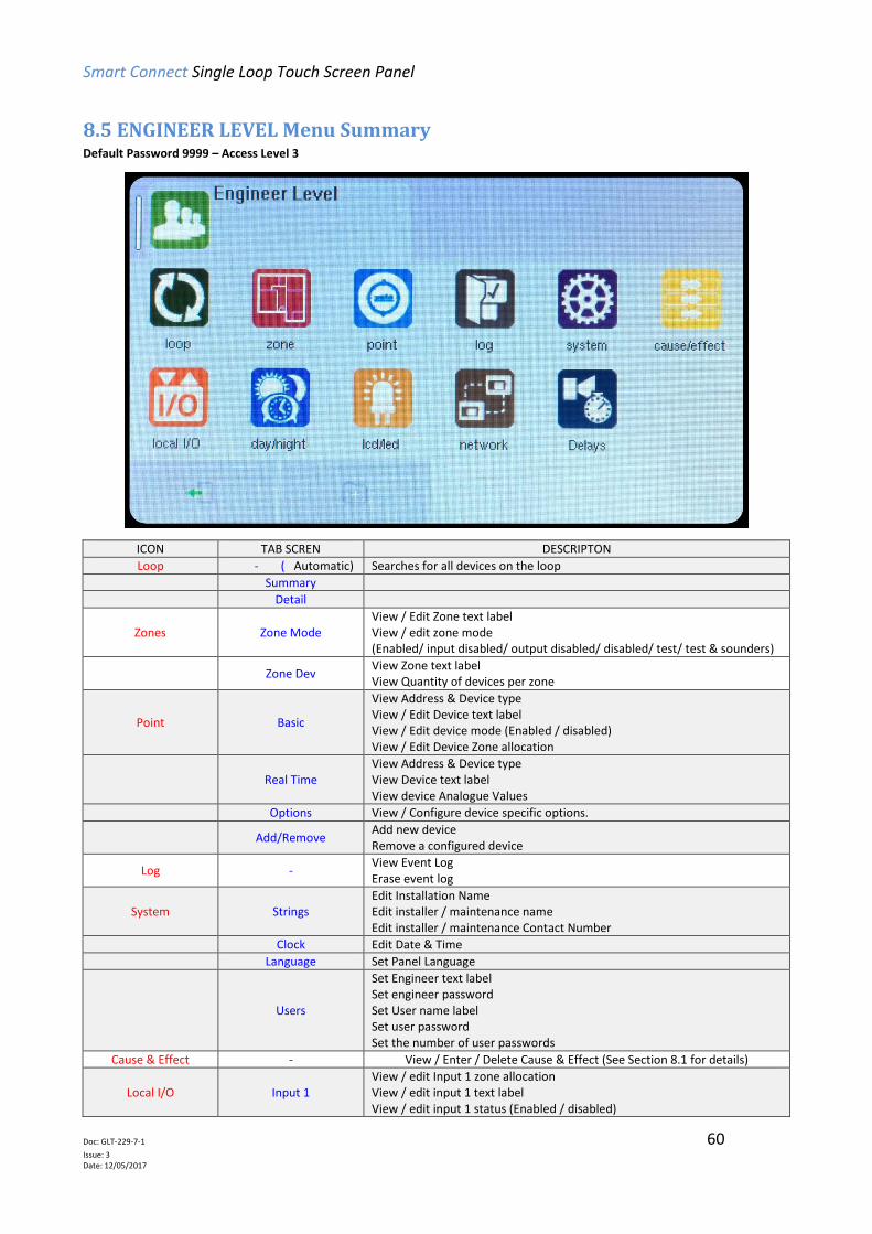
Smart Connect Single Loop Touch Screen Panel
Doc: GLT-229-7-1 60
Issue: 3 Date: 12/05/2017
8.5 ENGINEER LEVEL Menu Summary Default Password 9999 – Access Level 3
ICON TAB SCREN DESCRIPTON
Loop - ( Automatic) Searches for all devices on the loop
Summary
Detail
Zones Zone Mode View / Edit Zone text label View / edit zone mode (Enabled/ input disabled/ output disabled/ disabled/ test/ test & sounders)
Zone Dev View Zone text label View Quantity of devices per zone
Point Basic
View Address & Device type View / Edit Device text label View / Edit device mode (Enabled / disabled) View / Edit Device Zone allocation
Real Time View Address & Device type View Device text label View device Analogue Values
Options View / Configure device specific options.
Add/Remove Add new device Remove a configured device
Log - View Event Log Erase event log
System Strings Edit Installation Name Edit installer / maintenance name Edit installer / maintenance Contact Number
Clock Edit Date & Time
Language Set Panel Language
Users
Set Engineer text label Set engineer password Set User name label Set user password Set the number of user passwords
Cause & Effect - View / Enter / Delete Cause & Effect (See Section 8.1 for details)
Local I/O Input 1 View / edit Input 1 zone allocation View / edit input 1 text label View / edit input 1 status (Enabled / disabled)

Smart Connect Single Loop Touch Screen Panel
Doc: GLT-229-7-1 61
Issue: 3 Date: 12/05/2017
Input 2 View / edit Input 2 zone allocation View / edit input 2 text label View / edit input 2 status (Enabled / disabled)
Sounder 1 View / edit Sounder 1 zone allocation View / edit Sounder 1 text label View / edit Sounder 1 status (Enabled / disabled)
Sounder 2 View / edit Sounder 2 zone allocation View / edit Sounder 2 text label View / edit Sounder 2 status (Enabled / disabled)
Day / Night - Configure day / night timer (add Day settings)
LCD / LED - Test panel LEDs , LCD & Buzzer
Network RS 485 View / edit RS485 Port status (Enabled / disabled) View / edit Network Node Address
TCP-IP
View / edit TCP/IP Port status (Enabled / disabled) View / edit IP Address View / edit IP Port used View / edit IP Gateway Address View / edit IP Subnet Mask
CLOUD
View / edit Remote access mode (Enabled / disabled) View / edit cloud server IP address / URL View / edit IP Port used View panels MAC address
Delays - Toggle panel delays on or off

Smart Connect Single Loop Touch Screen Panel
Doc: GLT-229-7-1 62
Issue: 3 Date: 12/05/2017
8.6 CAUSE & EFFECT SETTINGS SUMMARY The table below shows the list of options available for each type of input (cause) and Output (Effect)
Select CAUSE
Input Type Selection 1 Selection 2 Options
Point Loop (1)
Address (1 - 254)
Alarm
Detector Alarm
MCP Alarm
Fault
Maintenance
Tech Warning ON
Tech Warning OFF
Local I/O Local I/O start
(1-2) Local I/O End
(1-2)
Fault
Alarm
Tech Warning ON
Tech Warning OFF
Zone Zone Start
(1 -254) Zone End (1-254)
Alarm
Detector Alarm
MCP Alarm
Fault
Maintenance
Tech Warning ON
Tech Warning OFF
Multi devices in alarm
Panel - -
Alarm
Detector Alarm
MCP Alarm
Fault
Maintenance
Tech Warning ON
Tech Warning OFF
Multi devices in alarm
Multi Zones in alarm

Smart Connect Single Loop Touch Screen Panel
Doc: GLT-229-7-1 63
Issue: 3 Date: 12/05/2017
Select EFFECT
Output Type Selection 1 Selection 2 Day Delay Night Delay Output
Point Loop (1)
Address (1 to 254)
(0-600) (0-600)
All On
Alarm + Beacon
Alert + Beacon
Emergency + Beacon
Alarm
Alert
Emergency
Flasher
All Off
Enable
Disable
Local I/O Local I/O start
(1-2) Local I/O end
(1-2)
(0-600) (0-600)
Alarm
Alert
Sounder Off
Enable
Disable
Zone Zone Start
(1 -254) Zone End (1-254)
(0-600) (0-600)
All On
Alarm + Beacon
Alert + Beacon
Emergency + Beacon
Alarm
Alert
Emergency
Beacon
Sounder + Beacon Off
Relay On
Relay Off
All Off
Disable Sounders
Enable Sounders
Disable Relays
Enable Relays
Enable Output
Disable Output
Panel - - (0-600) (0-600)
All On
Alarm + Beacon
Alert + Beacon
Emergency + Beacon
Alarm
Alert
Emergency
Beacon
Sounder + Beacon Off
Relay On
Relay Off
All Off
Disable Sounders
Enable Sounders
Disable Relays
Enable Relays
Enable Output
Disable Output

Smart Connect Single Loop Touch Screen Panel
Doc: GLT-229-7-1 64
Issue: 3 Date: 12/05/2017
9 - DISABLEMENTS
9.1 DISABLEMENTS ........................................................................................................................................... 65
9.2 ZONE DISABLEMENT ................................................................................................................................... 65
9.3 DEVICE DISABLEMENT ................................................................................................................................ 67

Smart Connect Single Loop Touch Screen Panel
Doc: GLT-229-7-1 65
Issue: 3 Date: 12/05/2017
9.1 DISABLEMENTS To aid commissioning and assist routine maintenance checks, various functions of the Smart Connect fire alarm system can be
disabled. The Smart Connect allows Disablement of Inputs in a zone, Outputs in a zone, a whole zone, or individual devices.
9.2 ZONE DISABLEMENT When a zone is disabled, the panel will not respond to any fault or fire signals it receives from that zone.
This might be used if the system requires routine maintenance, and the user needs the rest of the system to continue running, but
doesn’t want spurious false alarms.
The panel will respond in the usual manner to any events in any non-disabled zones.
Any number of zones can be disabled, but it is good practice to only disable one zone at a time.
A zone can be disabled as follows:
Enter the Engineer or User Password, Press the menu access
icon , and select the zone Icon (The disabling function is available to engineer & users). The panel shows the Zone menu
Select the Zone to Disable by pressing the “In” field. The status changes from enabled to Input Disabled. This would disable all detectors, manual call points, and Input interfaces in that zone. Select further zones in the same way, or Press exit to save. For further options, press the “In” field again.
The status changes from Input Disabled to Output Disabled. This would disable all Sounders and Output interfaces in that zone.
For further options, press the “In” field again. The status changes from Output Disabled to Disabled. This would disable everything in that zone.

Smart Connect Single Loop Touch Screen Panel
Doc: GLT-229-7-1 66
Issue: 3 Date: 12/05/2017
When zones have been disabled, the LCD display changes from
SYSTEM NORMAL to Disablement/Test. The screen shows:-
The number of zones disabled, The number of zones with just their inputs disabled. The number of zones with just their outputs disabled. and the total number of devices in those disabled zones. The General Disablement LED will be lit and also the zonal
disablement LEDs will be lit for any zone with disabled inputs.
The zonal disablement LEDs only apply to zones 1 to 16.
Details of the disabled zones can be viewed by pressing the
disabled zones icon
Details of the individual devices disabled can be viewed by
pressing the disabled loop devices icon
To re-enable a zone, use the same procedure, pressing the In field until it shows Enabled. It cycles through:-
Enabled
Input Disabled
Output Disabled
Disabled
Test
Test + Sounder

Smart Connect Single Loop Touch Screen Panel
Doc: GLT-229-7-1 67
Issue: 3 Date: 12/05/2017
9.3 DEVICE DISABLEMENT Rather than disable an entire zone, it is often useful to just disable one or more input devices or points (detector, call point, or
interface) within a zone, especially if they are malfunctioning and likely to cause a false alarm or repeatedly indicate a fault.
Enter the Engineer or User Password , Press the
menu access icon, and select the Point Icon (The disabling function is available to engineer & users). The panel shows the Point menu.
Press on the MODE field for the device to be disabled. Select further devices to disable if necessary, then press Exit to save.
When zones have been disabled, the LCD display changes from
SYSTEM NORMAL to Disablement/Test, as shown.
The screen shows the number of devices disabled.
The General Disablement LED will be lit, but the zonal
disablement LEDs will not light, unless all devices in that zone
have been disabled.
Details of the individual devices disabled can be viewed by pressing the disabled loop devices icon
To re-enable a device, use the same procedure, pressing the Mode field until it shows Enabled.
Once a device is disabled, the panel ignores any alarms or faults generated by the device. If all devices in a zone are disabled, the
panel will indicate a zone disablement. If subsequently one or more devices are re-enabled then the zone disablement indication
will be automatically cancelled.
To re-enable a disabled device, repeat the same procedure used for disabling the device, selecting Enable instead of Disable.

Smart Connect Single Loop Touch Screen Panel
Doc: GLT-229-7-1 68
Issue: 3 Date: 12/05/2017
10 - TEST MODE
10.1 WHY USE TEST MODE ............................................................................................................................... 69
10.2 TO PROGRAMME ZONE INTO TEST MODE ............................................................................................... 69
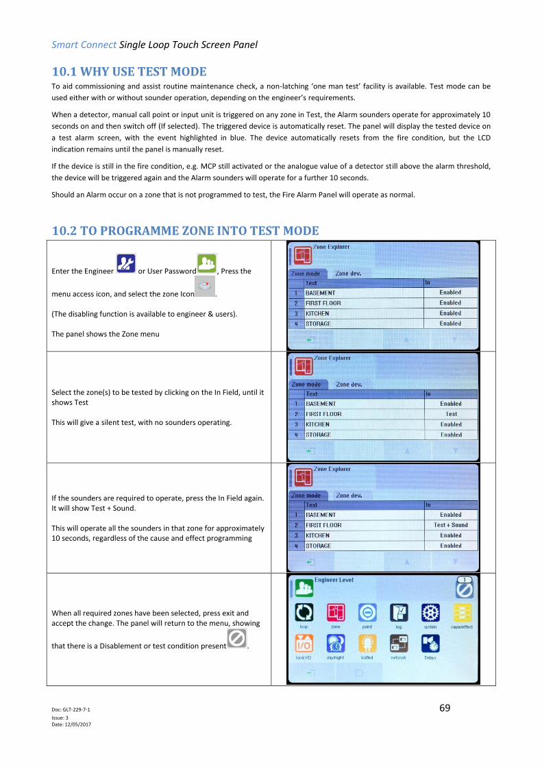
Smart Connect Single Loop Touch Screen Panel
Doc: GLT-229-7-1 69
Issue: 3 Date: 12/05/2017
10.1 WHY USE TEST MODE To aid commissioning and assist routine maintenance check, a non-latching ‘one man test’ facility is available. Test mode can be
used either with or without sounder operation, depending on the engineer’s requirements.
When a detector, manual call point or input unit is triggered on any zone in Test, the Alarm sounders operate for approximately 10
seconds on and then switch off (If selected). The triggered device is automatically reset. The panel will display the tested device on
a test alarm screen, with the event highlighted in blue. The device automatically resets from the fire condition, but the LCD
indication remains until the panel is manually reset.
If the device is still in the fire condition, e.g. MCP still activated or the analogue value of a detector still above the alarm threshold,
the device will be triggered again and the Alarm sounders will operate for a further 10 seconds.
Should an Alarm occur on a zone that is not programmed to test, the Fire Alarm Panel will operate as normal.
10.2 TO PROGRAMME ZONE INTO TEST MODE
Enter the Engineer or User Password , Press the
menu access icon, and select the zone Icon . (The disabling function is available to engineer & users). The panel shows the Zone menu
Select the zone(s) to be tested by clicking on the In Field, until it shows Test This will give a silent test, with no sounders operating.
If the sounders are required to operate, press the In Field again. It will show Test + Sound. This will operate all the sounders in that zone for approximately 10 seconds, regardless of the cause and effect programming
When all required zones have been selected, press exit and accept the change. The panel will return to the menu, showing
that there is a Disablement or test condition present .

Smart Connect Single Loop Touch Screen Panel
Doc: GLT-229-7-1 70
Issue: 3 Date: 12/05/2017
Press the exit icon to leave the menu. The screen will show that there are zones in test.
To view which zones are in test mode, press the zones in test icon.
Proceed to test the devices. The panel will show all test events on a separate test screen. The events will be highlighted blue to
When complete, take the panel out of test mode by selecting the zone icon. Click the “In” field until it shows enabled. Press exit and save changes in order to return the panel to normal.
Smart Connect Single Loop Touch Screen Panel
Doc: GLT-229-7-1 71
Issue: 3 Date: 12/05/2017
11 - NETWORKING
11.1 NETWORKING ........................................................................................................................................... 72
11.2 RING NETWORK ........................................................................................................................................ 72
11.3 BUS NETWORK .......................................................................................................................................... 72
11.4 CONFIGURING THE NETWORK ................................................................................................................. 72
11.5 RUNNING THE NETWORK ......................................................................................................................... 73
11.6 CONFIGURING TCP/IP CONNECTION…………………………………………………………………………………………………..73
11.7 CONFIGURING THE CLOUD SETTING……………………………………………………………………………………………………74

Smart Connect Single Loop Touch Screen Panel
Doc: GLT-229-7-1 72
Issue: 3 Date: 12/05/2017
11.1 NETWORKING The Smart Connect panel has built in network connections, so no additional hardware is needed to network panels together. Up to 64 control panels (CIEs) can be connected together, i.e. networked. The maximum distance between nodes is 1 km using a screened data cable, or 100m using a standard fireproof cable. The network can be configured with a ring or bus topology.
11.2 RING NETWORK In a ring network, each control panel is connected to 2 other control panels to form a ring. This has the same topology as the loops of addressable devices connected to each CIE. This has the advantage that no panels are lost if there is a single break in the network.
11.3 BUS NETWORK This is similar to a ring network but wired panel to panel without a return connection from last panel to first panel. It could also be referred to as a radial or spur network.
11.4 CONFIGURING THE NETWORK
Enter the engineer menu
Select the Network Menu , and press the RS485 tab The panel shows that the network connection is disabled (It`s default state).
Change the mode to Enabled. Set a node address. Note that each panel on the network must have a separate address.

Smart Connect Single Loop Touch Screen Panel
Doc: GLT-229-7-1 73
Issue: 3 Date: 12/05/2017
Repeat the above step for all panels on the network, then press
the Add icon to search and configure the network.
When the search is complete, the panel shows a list of network node addresses seen, and whether the panel sees a connection on Network port A (NET 1), and Network port B (NET 2). If the panel sees a connection it reports the port as UP. If it does not see a connection, it reports the port as down. (In this example we have a single panel)
11.5 RUNNING THE NETWORK On a Smart Connect panel, running in a network, all events are reported at all panels. All panels are able to silence & reset the
system, when a suitable access code has been entered.
Operation of outputs over the network is determined by the programmed cause & effect. Any input on the network can be
programmed to operate any output. The cause & effect is entered at the panel that has the INPUT CAUSE connected.
11.6 CONFIGURING TCP/IP CONNECTION The Smart Connect panel has a TCP/IP connection that allows the panel to report events to a central server. To do this, First the
TCP/IP address must be set.
From the Network Menu , press the TCP/IP tab. The panel shows that the TCP/IP connection is disabled (It`s default state).
Select DHCP for the LAN to assign the settings, or select manual to enter the settings by hand. If entering the settings by hand, just type the numbers. The panel will automatically insert the dots.
With only the TCP/IP configured, the panel will sit on a network, but would need 3
rd party software on a PC to do anything useful.
The cloud tab will need to be configured in order for the panel to link to the remote server.

Smart Connect Single Loop Touch Screen Panel
Doc: GLT-229-7-1 74
Issue: 3 Date: 12/05/2017
11.7 CONFIGURING THE CLOUD SETTINGS The Smart Connect panel has been designed to report events to a central server. This will allow authorised users to view the
current status of the panel. The settings are usually set at the factory, but can be configured by the installer if required.
From the Network Menu , press the Cloud tab. Enter Server and Port details as required. Make a note of the MAC address, as this will be needed to register the panel at the server.
The Mode setting determines whether remote access to the panel is enabled or disabled. To allow an engineer to interrogate the panel remotely, this should be set to enabled. This is to prevent access to a panel without a responsible person physically at the fire panel. This setting will time out after a short period of inactivity.
Smart Connect Single Loop Touch Screen Panel
Doc: GLT-229-7-1 75
Issue: 3 Date: 12/05/2017
12 - FAULT FINDING
12.1 LOOP WIRING FAULT FINDING ................................................................................................................. 76
12.2 LOOP CONTENTS FAULT FINDING ............................................................................................................ 77
12.3 ZONE FAULTS ............................................................................................................................................ 77
12.4 POWER SUPPLY FAULTS ............................................................................................................................ 78
12.5 EARTH FAULTS .......................................................................................................................................... 79
12.6 SYSTEM FAULT .......................................................................................................................................... 80
12.7 PANEL INPUT AND CONVENTIONAL SOUNDER FAULTS ........................................................................... 81
12.8 EVENT LOGS .............................................................................................................................................. 82
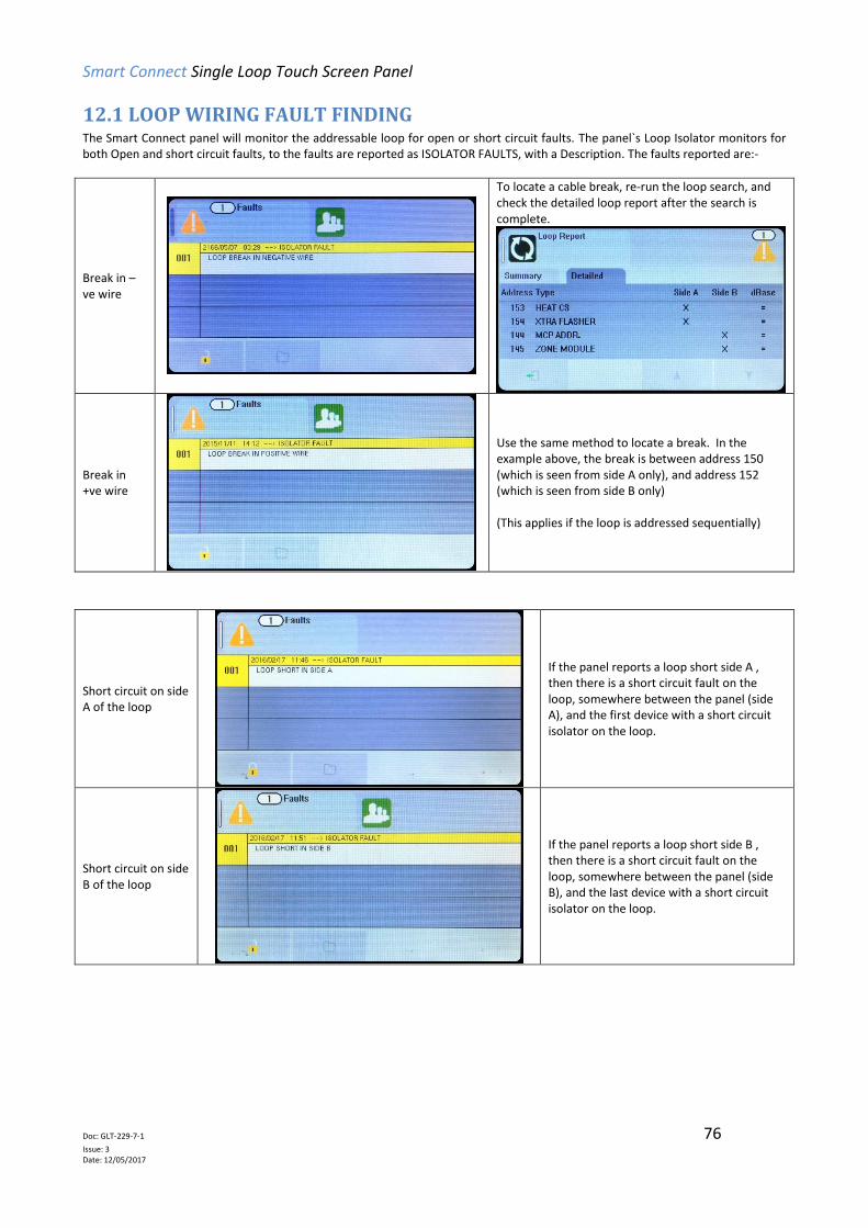
Smart Connect Single Loop Touch Screen Panel
Doc: GLT-229-7-1 76
Issue: 3 Date: 12/05/2017
12.1 LOOP WIRING FAULT FINDING The Smart Connect panel will monitor the addressable loop for open or short circuit faults. The panel`s Loop Isolator monitors for both Open and short circuit faults, to the faults are reported as ISOLATOR FAULTS, with a Description. The faults reported are:-
Break in –ve wire
To locate a cable break, re-run the loop search, and check the detailed loop report after the search is complete.
Break in +ve wire
Use the same method to locate a break. In the example above, the break is between address 150 (which is seen from side A only), and address 152 (which is seen from side B only) (This applies if the loop is addressed sequentially)
Short circuit on side A of the loop
If the panel reports a loop short side A , then there is a short circuit fault on the loop, somewhere between the panel (side A), and the first device with a short circuit isolator on the loop.
Short circuit on side B of the loop
If the panel reports a loop short side B , then there is a short circuit fault on the loop, somewhere between the panel (side B), and the last device with a short circuit isolator on the loop.
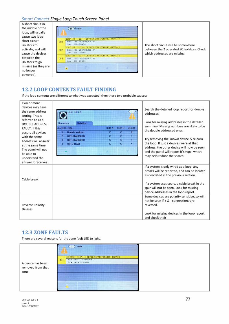
Smart Connect Single Loop Touch Screen Panel
Doc: GLT-229-7-1 77
Issue: 3 Date: 12/05/2017
A short circuit in the middle of the loop, will usually cause two loop short circuit isolators to activate, and will cause the devices between the isolators to go missing (as they are no longer powered).
The short circuit will be somewhere between the 2 operated SC isolators. Check which addresses are missing.
12.2 LOOP CONTENTS FAULT FINDING If the loop contents are different to what was expected, then there two probable causes:
Two or more devices may have the same address setting. This is referred to as a DOUBLE ADDRESS FAULT. If this occurs all devices with the same address will answer at the same time. The panel will not be able to understand the answer it receives
Search the detailed loop report for double addresses. Look for missing addresses in the detailed summary. Missing numbers are likely to be the double addressed ones. Try removing the known device & relearn the loop. If just 2 devices were at that address, the other device will now be seen, and the panel will report it`s type, which may help reduce the search
Cable break
If a system is only wired as a loop, any breaks will be reported, and can be located as described in the previous section. If a system uses spurs, a cable break in the spur will not be seen. Look for missing device addresses in the loop report.
Reverse Polarity Devices
Some devices are polarity sensitive, so will not be seen if + & - connections are reversed. Look for missing devices in the loop report, and check their
12.3 ZONE FAULTS There are several reasons for the zone fault LED to light.
A device has been removed from that zone.
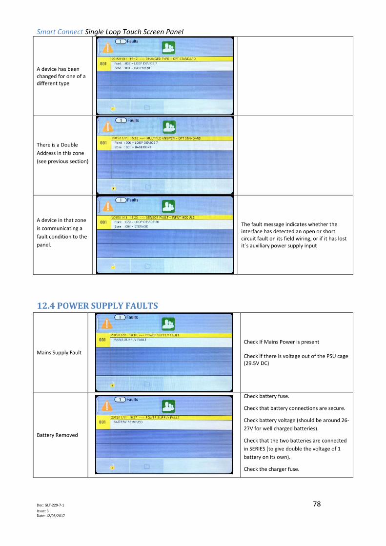
Smart Connect Single Loop Touch Screen Panel
Doc: GLT-229-7-1 78
Issue: 3 Date: 12/05/2017
A device has been changed for one of a different type
There is a Double
Address in this zone
(see previous section)
A device in that zone
is communicating a
fault condition to the
panel.
The fault message indicates whether the interface has detected an open or short circuit fault on its field wiring, or if it has lost it`s auxiliary power supply input
12.4 POWER SUPPLY FAULTS
Mains Supply Fault
Check If Mains Power is present Check if there is voltage out of the PSU cage (29.5V DC)
Battery Removed
Check battery fuse.
Check that battery connections are secure.
Check battery voltage (should be around 26-
27V for well charged batteries).
Check that the two batteries are connected
in SERIES (to give double the voltage of 1
battery on its own).
Check the charger fuse.

Smart Connect Single Loop Touch Screen Panel
Doc: GLT-229-7-1 79
Issue: 3 Date: 12/05/2017
Charger Fault
The panel has determined that the power supply is not charging the batteries. This is likely to be a problem with the Charger PCB. Contact your supplier to arrange a replacement charger PCB
Battery high impedance fault
The panel has measured the battery internal resistance and has determined it is too high. The batteries will need to be replaced.
12.5 EARTH FAULTS An EARTH fault indicates that something is shorting to earth (usually through the cable screen). Disconnect the earth screens one at
a time to determine the problem line. (Note: connecting other equipment, e.g. a mains powered laptop, to the panel can give an
earth fault)
The earth fault message will indicate if it is a Positive or Negative voltage shorting to earth.
Earth Positive Fault
Most Earth faults occur on the Addressable loop. As a first check disconnect all the loop connections, and reset the panel. If no earth fault is reported the fault is on the loop. Locate the fault by splitting the loop in half, connecting one side of the loop at a time, then sub dividing the “bad section”. Look for the cable screen shorting to loop + If the fault is not on the loop, use a similar method to investigate all other circuits.
Earth Negative Fault
Use the same method , but look for shorts to loop -ve
Note that for the on board conventional sounder circuits, in the off condition, both sounder + and sounder – terminals are POSITIVE
with respect to earth, so a short circuit to either would give a positive earth fault.
***DO NOT DISCONNECT THE MAINS EARTH CONNECTION. THIS WILL CAUSE A PROBLEM WITH THE PANELS OPERATION***

Smart Connect Single Loop Touch Screen Panel
Doc: GLT-229-7-1 80
Issue: 3 Date: 12/05/2017
12.6 SYSTEM FAULT A system fault is an abnormal microprocessor running condition due to various unexpected phenomena.
This will result in the panel attempting to correct itself. Should this fault occur, the System Fault LED, General Fault LED, General
Fault relay and internal fault buzzer will be constantly active. A system fault indication can be cleared by pressing the system fault
reset button located underneath the PCB. If the fault does not clear please consult your distributor.
Location of System Fault Reset Button from front of the panel
Viewed from side of the panel
Viewed from the rear of the PCB

Smart Connect Single Loop Touch Screen Panel
Doc: GLT-229-7-1 81
Issue: 3 Date: 12/05/2017
12.7 PANEL INPUT AND CONVENTIONAL SOUNDER FAULTS
LOCAL INPUT OPEN
Check the local input has an EOL resistor fitted Check that the EOL resistor is the correct value (4.7 kΩ) Check that there are no cable breaks or loose connections
LOCAL INPUT SHORTED
Check that there are no cable short circuits on the circuits. Check that the EOL resistor is the correct value (4.7 kΩ) Check that there are no Normally closed switches connected to this circuit.
LOCAL OUTPUT OPEN
Check the local Output (Sounder Circuit) has an EOL resistor fitted Check that the EOL resistor is the correct value (4.7 kΩ) Check that there are no cable breaks or loose connections
LOCAL OUTPUT SHORTED
Check that there are no cable short circuits on the circuits. Check that there are no non-polarised devices connected to the circuit.
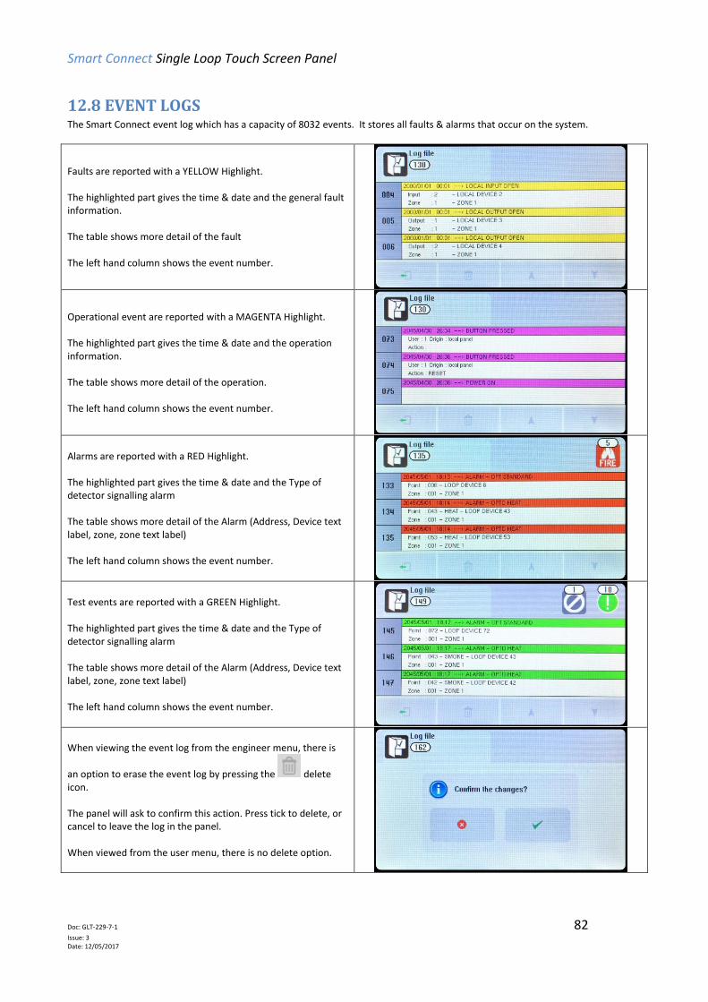
Smart Connect Single Loop Touch Screen Panel
Doc: GLT-229-7-1 82
Issue: 3 Date: 12/05/2017
12.8 EVENT LOGS The Smart Connect event log which has a capacity of 8032 events. It stores all faults & alarms that occur on the system.
Faults are reported with a YELLOW Highlight. The highlighted part gives the time & date and the general fault information. The table shows more detail of the fault The left hand column shows the event number.
Operational event are reported with a MAGENTA Highlight. The highlighted part gives the time & date and the operation information. The table shows more detail of the operation. The left hand column shows the event number.
Alarms are reported with a RED Highlight. The highlighted part gives the time & date and the Type of detector signalling alarm The table shows more detail of the Alarm (Address, Device text label, zone, zone text label) The left hand column shows the event number.
Test events are reported with a GREEN Highlight. The highlighted part gives the time & date and the Type of detector signalling alarm The table shows more detail of the Alarm (Address, Device text label, zone, zone text label) The left hand column shows the event number.
When viewing the event log from the engineer menu, there is
an option to erase the event log by pressing the delete icon. The panel will ask to confirm this action. Press tick to delete, or cancel to leave the log in the panel. When viewed from the user menu, there is no delete option.
Smart Connect Single Loop Touch Screen Panel
Doc: GLT-229-7-1 83
Issue: 3 Date: 12/05/2017
13 - STANDBY BATTERY REQUIREMENTS
13.1 STANDBY BATTERY REQUIREMENTS ........................................................................................................ 84
13.2 DEVICE CURRENT RATINGS ....................................................................................................................... 84
13.3 DEVICE COMPATIBILITY CHART…………………………………………………………………………………………………………..85
13.4 STANDBY BATTERY CALCULATION ............................................................................................................ 86

Smart Connect Single Loop Touch Screen Panel
Doc: GLT-229-7-1 84
Issue: 3 Date: 12/05/2017
13.1 STANDBY BATTERY REQUIREMENTS It is the responsibility of the system designer to choose batteries that will give the required system standby time. The following
pages give the information needed to help determine the minimum battery requirements.
13.2 DEVICE CURRENT RATINGS The Following Table shows the Quiescent, Alarm currents of the main parts of a Smart Connect Fire Alarm System:
DEVICE QUIESCENT ALARM
MKII-AOP 0.5 5
MKII-AOH 0.5 5
MKII-AHR 0.5 5
MKII-AHF 0.5 5
ZT-CP3/AD 0.45 2.3
ZT-CP3/AD/WP 0.45 2.3
MKII-AXT/x 0.65 4.5
MKII-AXTB/x 2.3 20.3
MKII-SSB 0.65 5.5
ZRAP/x 2.3 6.4
ZRAPB/x 2.3 20.3
ZAI-MI 1 3.6
ZAIO-MI 1 2
ZASC-MI 0.6 0.8
ZAZM-MI 3.5 13.2
ZAIOI/230 1.5 4.6
SMM/B 1.1 12
Wi-Fyre Transponder 12 12
MKII-CB n/a n/a
MKII-CB/D n/a n/a
MKII-IB 0.05 7
MKII-ARL/x 0.5 5
The Maximum per loop values given above are a guideline, based on the assumption that other devices on the loop do not cause
the total loop current to exceed the loop limit of 500mA. Current readings may change in future updates.
*AXTB, ZRAP & ZRAPB Dip settings: 1000, current varies per switch settings.

Smart Connect Single Loop Touch Screen Panel
Doc: GLT-229-7-1 85
Issue: 3 Date: 12/05/2017
13.3 Device Compatibility Chart
*AXTB, ZRAP & ZRAPB Dip settings: 1000, current varies per switch settings. Current readings may change in future updates.

Smart Connect Single Loop Touch Screen Panel
Doc: GLT-229-7-1 86
Issue: 3 Date: 12/05/2017
13.4 STANDBY BATTERY CALCULATION In order to calculate the standby battery size required, the following formula can be used:-
Battery Size (Standby time in Amp Hours) = 1.25 x [(TALM x IALM) + (TSBY x (IQP + IQZ))]
Where:
TALM = Maximum time in hours required for the alarm [½ hour is most common time]
IALM = Total Alarm Current in amps
IALM-SND = Alarm Current of Sounders in amps
TSBY = Standby time in hours for the system after mains failure [normally 24, 48 or 72 hr]
IQP = Quiescent current in amps of control panel in fault condition [because of mains failure]
IAP = Alarm current in amps of control panel
IQL = Quiescent current in amps of all loop devices.
Typical Example:
A system comprises of a 1 Loop Smart Connect panel, with 80 Addressable Optical Smoke Detectors, 15 Addressable Manual Call
Points, 20 Sounders and the required standby is 24 hours. It will need to operate in alarm for ½ hour.
Calculate the battery size required.
TALM = 0.5 Hr
IALM-SND = 20 x 0.004 =0.08A
TSBY= 24 Hr
IQP = 0.20A
IAP = 0.19A
IQL = 80 x 0.00044 + 15 x 0.001 + 20 x 0.0005 = 0.0602A
IALM = IALM-SND + IAP + IQL = 0.08 + 0.19 + 0.0602 = 0.3302
Therefore using the equation:
Battery Size (Standby time in Amp Hours) = 1.25 x [( TALM x IALM) + ( TSBY x ( IQP + IQL))]
Battery Size (Standby time in Amp Hours) = 1.25 x [(0.5 x 0.33) + (24 x (0.20 + 0.06))]
Battery Size (Standby time in Amp Hours) = 1.25 x [(0.5 x 0.33) + (24 x 0.26)]
Battery Size (Standby time in Amp Hours) = 1.25 x [0.165 + 6.24]
Battery Size (Standby time in Amp Hours) = 1.25 x 6.405
Battery Size (Standby time in Amp Hours) = 8.01 Amp Hours
For a system like this, 2 x 12V sealed lead acid batteries must be used each with a capacity greater than 8.01 Ah. For example,
12Ah
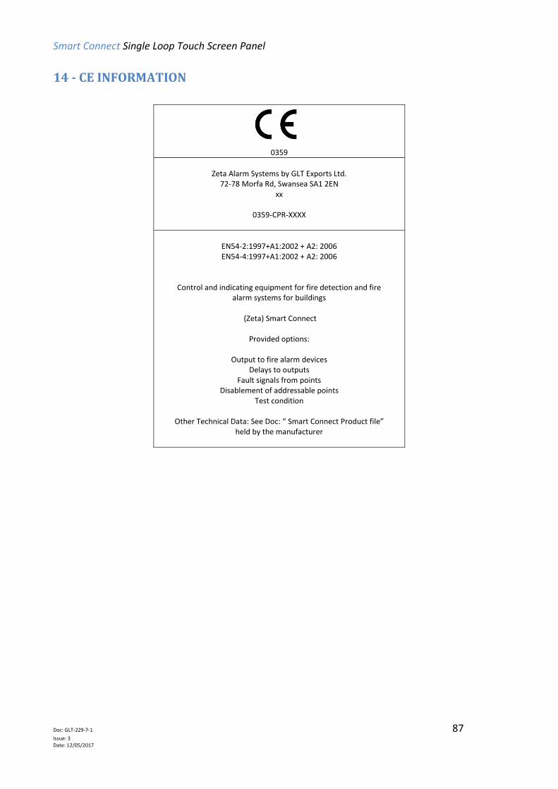
Smart Connect Single Loop Touch Screen Panel
Doc: GLT-229-7-1 87
Issue: 3 Date: 12/05/2017
14 - CE INFORMATION
0359
Zeta Alarm Systems by GLT Exports Ltd.
72-78 Morfa Rd, Swansea SA1 2EN xx
0359-CPR-XXXX
EN54-2:1997+A1:2002 + A2: 2006 EN54-4:1997+A1:2002 + A2: 2006
Control and indicating equipment for fire detection and fire alarm systems for buildings
(Zeta) Smart Connect
Provided options:
Output to fire alarm devices
Delays to outputs Fault signals from points
Disablement of addressable points Test condition
Other Technical Data: See Doc: “ Smart Connect Product file”
held by the manufacturer
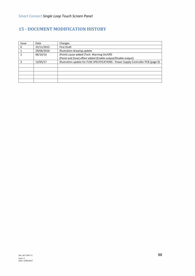
Smart Connect Single Loop Touch Screen Panel
Doc: GLT-229-7-1 88
Issue: 3 Date: 12/05/2017
15 - DOCUMENT MODIFICATION HISTORY
Issue Date Changes
0 25/11/2015 First Draft
1 29/06/2016 Illustration drawing update
2 06/10/16 (Point) cause added (Tech. Warning On/Off) (Panel and Zone) effect added (Enable output/Disable output)
3 12/05/17 Illustration update for FUSE SPECIFICATIONS - Power Supply Controller PCB (page 9)