Embed Size (px)
Citation preview

Installation Manual
IMPORTANT:TO THE INSTALLER.It is the responsibility ofthe Installer to ensure thatthe water supply to thedispensing equipment isprovided with protectionagainst backflow by an airgap as defined inANSI/ASME A112.1.2-1979;or an approved vacuumbreaker or other suchmethod as proved effectiveby test.
Water pipe connectionsand fixtures directlyconnected to a potablewater supply shall besized, installed, andmaintained according toFederal, State, and LocalCodes.
VANTAGEPRE-MIX DISPENSER
PRINTED IN U.S.AIMI CORNELIUS INC; 1997Ó
IMI CORNELIUS INC g One Cornelius Place g Anoka, MN 55303-6234
Telephone (800) 238-3600 Facsimile (612) 422-3246
Part No. 560001790August 11, 1997Control Code ATHIS DOCUMENT CONTAINS IMPORTANT INFORMATIONThis Manual must be read and understood before installing or operating this equipment

i 560001790
TABLE OF CONTENTSPage
SAFETY 1. . . . . . . . . . . . . . . . . . . . . . . . . . . . . . . . . . . . . . . . . . . . . . . . . . . . . . . . . . . . . . . . . .
SAFETY INFORMATION 1. . . . . . . . . . . . . . . . . . . . . . . . . . . . . . . . . . . . . . . . . . . . . .RECOGNIZE SAFETY INFORMATION 1. . . . . . . . . . . . . . . . . . . . . . . . . . . . . . .UNDERSTAND SIGNAL WORDS 1. . . . . . . . . . . . . . . . . . . . . . . . . . . . . . . . . . . .FOLLOW SAFETY INSTRUCTIONS 1. . . . . . . . . . . . . . . . . . . . . . . . . . . . . . . . .
GENERAL INFORMATION 3. . . . . . . . . . . . . . . . . . . . . . . . . . . . . . . . . . . . . . . . . . . . . . . . . .
GENERAL DESCRIPTION 3. . . . . . . . . . . . . . . . . . . . . . . . . . . . . . . . . . . . . . . . . . . . . .UNIT DESCRIPTION 3. . . . . . . . . . . . . . . . . . . . . . . . . . . . . . . . . . . . . . . . . . . . . . . . . . .WARRANTY REFERENCE INFORMATION 3. . . . . . . . . . . . . . . . . . . . . . . . . . . . . . .THEORY OF OPERATION 5. . . . . . . . . . . . . . . . . . . . . . . . . . . . . . . . . . . . . . . . . . . . . .
INSTALLATION 7. . . . . . . . . . . . . . . . . . . . . . . . . . . . . . . . . . . . . . . . . . . . . . . . . . . . . . . . . . . .
UNPACKING AND INSPECTION 7. . . . . . . . . . . . . . . . . . . . . . . . . . . . . . . . . . . . . . . .IDENTIFICATION OF LOOSE-SHIPPED PARTS 7. . . . . . . . . . . . . . . . . . . . . . . . . . .SELECTING LOCATION 7. . . . . . . . . . . . . . . . . . . . . . . . . . . . . . . . . . . . . . . . . . . . . . . .INSTALLATION 8. . . . . . . . . . . . . . . . . . . . . . . . . . . . . . . . . . . . . . . . . . . . . . . . . . . . . . . .
INSTALLING UNIT ON COUNTERTOP 8. . . . . . . . . . . . . . . . . . . . . . . . . . . . . . .FILL WATER TANK AND START REFRIGERATION SYSTEM 8. . . . . . . . . . .ROUTING AND CONNECTING PRODUCT INLET LINES 9. . . . . . . . . . . . . .INSTALLING DISPENSING VALVES KNOBS 9. . . . . . . . . . . . . . . . . . . . . . . . .CONNECTING CO2 GAS LINES TO PRODUCT TANKS 9. . . . . . . . . . . . . . .
PREPARING UNIT FOR OPERATION 10. . . . . . . . . . . . . . . . . . . . . . . . . . . . . . . . . . . .UNIT OPERATION 10. . . . . . . . . . . . . . . . . . . . . . . . . . . . . . . . . . . . . . . . . . . . . . . . . . . . .
OPERATOR’S INSTRUCTIONS 11. . . . . . . . . . . . . . . . . . . . . . . . . . . . . . . . . . . . . . . . . . . . .
OPERATING CONTROLS 11. . . . . . . . . . . . . . . . . . . . . . . . . . . . . . . . . . . . . . . . . . . . . .DISPENSING VALVE 11. . . . . . . . . . . . . . . . . . . . . . . . . . . . . . . . . . . . . . . . . . . . . .
DAILY PRE-OPERATION CHECK 11. . . . . . . . . . . . . . . . . . . . . . . . . . . . . . . . . . . . . . . .UNIT OPERATION 11. . . . . . . . . . . . . . . . . . . . . . . . . . . . . . . . . . . . . . . . . . . . . . . . . . . . .ADJUSTMENTS 11. . . . . . . . . . . . . . . . . . . . . . . . . . . . . . . . . . . . . . . . . . . . . . . . . . . . . . .
PRODUCT TANK CO2 REGULATORS 11. . . . . . . . . . . . . . . . . . . . . . . . . . . . . . .ADJUSTING DISPENSED PRODUCT FLOW RATE 11. . . . . . . . . . . . . . . . . . .
REPLENISHING CO2 SUPPLY 12. . . . . . . . . . . . . . . . . . . . . . . . . . . . . . . . . . . . . . . . . .REPLENISHING PRODUCT SUPPLY 12. . . . . . . . . . . . . . . . . . . . . . . . . . . . . . . . . . . .CLEANING AND SANITIZING 12. . . . . . . . . . . . . . . . . . . . . . . . . . . . . . . . . . . . . . . . . . .
DAILY CLEANING OF UNIT 12. . . . . . . . . . . . . . . . . . . . . . . . . . . . . . . . . . . . . . . .SANITIZING UNIT 12. . . . . . . . . . . . . . . . . . . . . . . . . . . . . . . . . . . . . . . . . . . . . . . . .
CHECKING DROP-IN REFRIGERATION ASSEMBLY CONDENSER COILFOR RESTRICTIONS 12. . . . . . . . . . . . . . . . . . . . . . . . . . . . . . . . . . . . . . . . . . . . . . . . . .CHECKING ICE WATER BATH 13. . . . . . . . . . . . . . . . . . . . . . . . . . . . . . . . . . . . . . . . . .CLEANING CO2 GAS CHECK VALVES 13. . . . . . . . . . . . . . . . . . . . . . . . . . . . . . . . . .
SERVICE AND MAINTENANCE 15. . . . . . . . . . . . . . . . . . . . . . . . . . . . . . . . . . . . . . . . . . . . .
PREPARING UNIT FOR SHIPPING OR RELOCATING 15. . . . . . . . . . . . . . . . . . . . .HOOD, FRONT ACCESS PANEL AND DRIP TRAY REMOVAL 15. . . . . . . . . . . . . .
HOOD REMOVAL 15. . . . . . . . . . . . . . . . . . . . . . . . . . . . . . . . . . . . . . . . . . . . . . . . .
ii560001790
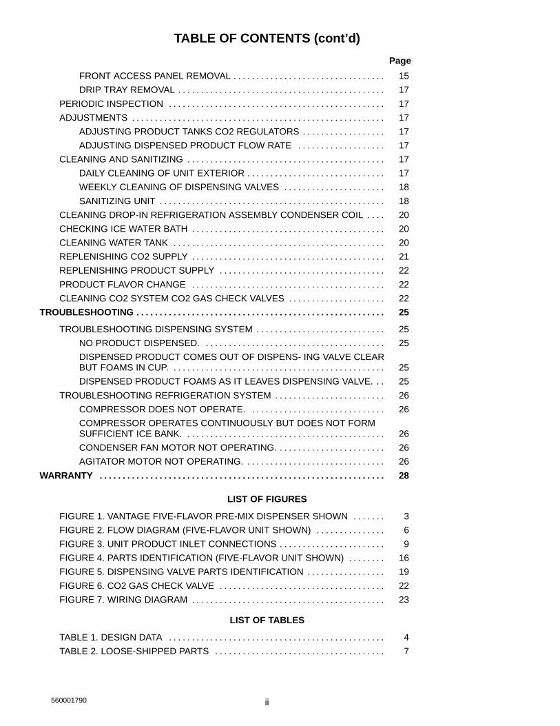
TABLE OF CONTENTS (cont’d)Page
FRONT ACCESS PANEL REMOVAL 15. . . . . . . . . . . . . . . . . . . . . . . . . . . . . . . . .DRIP TRAY REMOVAL 17. . . . . . . . . . . . . . . . . . . . . . . . . . . . . . . . . . . . . . . . . . . . .
PERIODIC INSPECTION 17. . . . . . . . . . . . . . . . . . . . . . . . . . . . . . . . . . . . . . . . . . . . . . .ADJUSTMENTS 17. . . . . . . . . . . . . . . . . . . . . . . . . . . . . . . . . . . . . . . . . . . . . . . . . . . . . . .
ADJUSTING PRODUCT TANKS CO2 REGULATORS 17. . . . . . . . . . . . . . . . . .ADJUSTING DISPENSED PRODUCT FLOW RATE 17. . . . . . . . . . . . . . . . . . .
CLEANING AND SANITIZING 17. . . . . . . . . . . . . . . . . . . . . . . . . . . . . . . . . . . . . . . . . . .DAILY CLEANING OF UNIT EXTERIOR 17. . . . . . . . . . . . . . . . . . . . . . . . . . . . . .WEEKLY CLEANING OF DISPENSING VALVES 18. . . . . . . . . . . . . . . . . . . . . .SANITIZING UNIT 18. . . . . . . . . . . . . . . . . . . . . . . . . . . . . . . . . . . . . . . . . . . . . . . . .
CLEANING DROP-IN REFRIGERATION ASSEMBLY CONDENSER COIL 20. . . .CHECKING ICE WATER BATH 20. . . . . . . . . . . . . . . . . . . . . . . . . . . . . . . . . . . . . . . . . .CLEANING WATER TANK 20. . . . . . . . . . . . . . . . . . . . . . . . . . . . . . . . . . . . . . . . . . . . . .REPLENISHING CO2 SUPPLY 21. . . . . . . . . . . . . . . . . . . . . . . . . . . . . . . . . . . . . . . . . .REPLENISHING PRODUCT SUPPLY 22. . . . . . . . . . . . . . . . . . . . . . . . . . . . . . . . . . . .PRODUCT FLAVOR CHANGE 22. . . . . . . . . . . . . . . . . . . . . . . . . . . . . . . . . . . . . . . . . .CLEANING CO2 SYSTEM CO2 GAS CHECK VALVES 22. . . . . . . . . . . . . . . . . . . . .
TROUBLESHOOTING 25. . . . . . . . . . . . . . . . . . . . . . . . . . . . . . . . . . . . . . . . . . . . . . . . . . . . . .
TROUBLESHOOTING DISPENSING SYSTEM 25. . . . . . . . . . . . . . . . . . . . . . . . . . . .NO PRODUCT DISPENSED. 25. . . . . . . . . . . . . . . . . . . . . . . . . . . . . . . . . . . . . . .DISPENSED PRODUCT COMES OUT OF DISPENS- ING VALVE CLEARBUT FOAMS IN CUP. 25. . . . . . . . . . . . . . . . . . . . . . . . . . . . . . . . . . . . . . . . . . . . . .DISPENSED PRODUCT FOAMS AS IT LEAVES DISPENSING VALVE. 25. .
TROUBLESHOOTING REFRIGERATION SYSTEM 26. . . . . . . . . . . . . . . . . . . . . . . .COMPRESSOR DOES NOT OPERATE. 26. . . . . . . . . . . . . . . . . . . . . . . . . . . . .COMPRESSOR OPERATES CONTINUOUSLY BUT DOES NOT FORMSUFFICIENT ICE BANK. 26. . . . . . . . . . . . . . . . . . . . . . . . . . . . . . . . . . . . . . . . . . .CONDENSER FAN MOTOR NOT OPERATING. 26. . . . . . . . . . . . . . . . . . . . . . .AGITATOR MOTOR NOT OPERATING. 26. . . . . . . . . . . . . . . . . . . . . . . . . . . . . .
WARRANTY 28. . . . . . . . . . . . . . . . . . . . . . . . . . . . . . . . . . . . . . . . . . . . . . . . . . . . . . . . . . . . . .
LIST OF FIGURES
FIGURE 1. VANTAGE FIVE-FLAVOR PRE-MIX DISPENSER SHOWN 3. . . . . . .FIGURE 2. FLOW DIAGRAM (FIVE-FLAVOR UNIT SHOWN) 6. . . . . . . . . . . . . . .FIGURE 3. UNIT PRODUCT INLET CONNECTIONS 9. . . . . . . . . . . . . . . . . . . . . . .FIGURE 4. PARTS IDENTIFICATION (FIVE-FLAVOR UNIT SHOWN) 16. . . . . . . .FIGURE 5. DISPENSING VALVE PARTS IDENTIFICATION 19. . . . . . . . . . . . . . . . .FIGURE 6. CO2 GAS CHECK VALVE 22. . . . . . . . . . . . . . . . . . . . . . . . . . . . . . . . . . . .FIGURE 7. WIRING DIAGRAM 23. . . . . . . . . . . . . . . . . . . . . . . . . . . . . . . . . . . . . . . . . .
LIST OF TABLES
TABLE 1. DESIGN DATA 4. . . . . . . . . . . . . . . . . . . . . . . . . . . . . . . . . . . . . . . . . . . . . . .TABLE 2. LOOSE-SHIPPED PARTS 7. . . . . . . . . . . . . . . . . . . . . . . . . . . . . . . . . . . . .

5600017901
SAFETY
SAFETY INFORMATION
Recognize Safety InformationThis is the safety-alert symbol. When you see thissymbol on our machine or in this manual, be alert tothe potentional for personal injury.
Follow recommended precautions and safe operatingpractices.
DANGERUnderstand Signal WordsA signal word - DANGER, WARNING, OR CAUTIONis used with the safety-alert symbol. DANGER identi-fies the most serious hazards.
Safety signs with signal word DANGER or WARNINGare typically near specific hazards.
WARNINGGeneral precautions are listed on CAUTION safetysigns. CAUTION also calls attention to safety mes-sages in this manual. CAUTION
Follow Safety InstructionsCarefully read all safety messages in this manual and on your machine safety signs.Keep safety signs in good condition. Replace missing or damaged safety signs.Learn how to operate the machine and how to use the controls properly. Do not letanyone operate the machine without instructions. Keep your machine in proper work-ing condition. Unauthorized modifications to the machine may impair function and/orsafety and affect the machine life.
Claims: In the event of shortage, notify the carrier as well as IMI Cornelius immediately. In the event of dam-age, notify the carrier. IMI Cornelius is not responsible for damage occurring in transit, but will gladlyrender assistance necessary to pursue your claim. Merchandise must be inspected for concealeddamage within 15 days of receipt.
Warranty Registration Date(to be filled out by customer)
Unit Part Number:Serial Number:Install Date:Local AuthorizedService Center:

560001790 2
THIS PAGE LEFT BLANK INTENTIONALLY

3 560001790
GENERAL INFORMATIONIMPORTANT: To the user of this manual -- This manual is a guide for installing, operating, andmaintaining this equipment. Refer to Table of Contents for page location of detailed informationpertaining to questions that arise during installation, operation, service and maintenance, ortroubleshooting this equipment.
This Unit contains no User serviceable parts and must be installed and serviced by a qualified Service Person.
GENERAL DESCRIPTIONThis section gives the Unit description, theory of operation, and design data for the four and five-flavor VantagePre-Mix Dispensers hereafter referred to as Units.
UNIT DESCRIPTIONThe Units are compact with stainless-steel lower housings. The Units may be island-mounted or installed onfront or rear countertop. These Units are equipped with drop-in type 1/3 H.P. refrigeration assemblies and areremovable for service and maintenance.
Installation of Unit on countertop, installation of LOOSE-SHIPPED PARTS, filling water tank with water,connection of Unit to product tanks with regulated CO2 pressure, and connection of Unit to electrical outlet withproper electrical requirements is all that is required to set Unit up for operation.
CAUTION: Before shipping, storing, or relocating this Unit, the product systems must besanitized and all sanitizing solution must be purged from the product systems with potablewater. A freezing ambient environment will cause residual water remaining inside the Unit
to freeze resulting in damage to the internal components.
WARRANTY REFERENCE INFORMATIONWarranty Registration Date
(to be filled out by customer)Unit Part Number:Serial Number:Install Date:Local AuthorizedService Center:
FIGURE 1. VANTAGE FIVE-FLAVOR PRE-MIX DISPENSER SHOWN

560001790 4
Table 1. Design Data
Unit Part Numbers:60 Hz Units
Four-Flavor 120 VAC, 60 Hz 281604XXXFive-Flavor 120 VAC, 60 Hz 281605XXXFour-Flavor 230 VAC, 60 Hz 481604XXXFive-Flavor 230 VAC, 60 Hz 481605XXX
50 Hz Units (CE Units)Four-Flavor 230 VAC, 50 Hz 481704XXXFive-Flavor 230 VAC, 50 Hz 481705XXX
Overall Dimensions:Width 15-inchesHeight 18-1/2 inchesDepth (with drip tray in place on Unit) 26-inches
Weight (approximate):Shipping (one carton) 90 poundsDry Weight (approximate) 88 poundsIce Bank Weight (approximate) 12 poundsDrop-In Refrigeration Assembly 48 pounds
Water Bath Capacity (no ice bank) 5.75 gallons
Dispensing Rate: (approximate)
No. ofValves
No. of 6-oz.Drinks/Min
*No. of drinks38°F or below
(minimum)
4 4 100
5 4 100
*Number of 6-oz. drinks dispensed 38°F or below @ 75°F product inlet temperature and 75°F ambient.
Refrigeration Requirement:Refrigerant See Unit Nameplate
Ambient Operating Temperature 50°F to 105°F
Electrical Requirements:Operating Voltage See Unit NameplateCurrent Draw See Unit Nameplate

5 560001790
THEORY OF OPERATION(see Figure 2)
A CO2 cylinder delivers carbon dioxide (CO2) gas through adjustable CO2 regulators to the product tanks. Whendispensing valve is opened, CO2 pressure exerted upon product tank contents pushes product from the producttank, through the Unit cooling coil, and on to the dispensing valve resulting in a dispensed drink.
When Unit power cord is plugged into an electrical outlet, the compressor, condenser fan motor, and agitatormotor will start and begin forming an ice bank in the water tank. When full ice bank has been formed,compressor and condenser fan motor will stop but agitator motor will continue to operate circulating ice water inwater tank. The water tank ice bank control will cycle compressor and condenser fan motor on and off asrequired to maintain a full ice bank.
WARNING: CO2 displaces oxygen. Strict attention must be observed in the prevention ofCO2 (carbon dioxide) gas leaks in the entire CO2 and soft drink system. If a CO2 gas leak issuspected, particularly in a small area, immediately ventilate the contaminated area before
attempting to repair the leak. Personnel exposed to high concentration of CO2 gas will experiencetremors which are followed rapidly by loss of consciousness and suffocation.

6560001790
FIG
UR
E2.
FLO
WD
IAG
RA
M(F
IVE-
FLAV
OR
UN
ITSH
OW
N)

7 5600001790
INSTALLATION
This section covers unpacking and inspection, identification of LOOSE-SHIPPED PARTS, selecting location,installing Unit, preparing Unit for operation, and Unit operation.
UNPACKING AND INSPECTION(see Figure 4)
NOTE: The Unit was thoroughly inspected before leaving the factory and the carrier has accepted andsigned for it. Any damage or irregularities should be noted at time of delivery (or not later than 15 daysfrom date of delivery) and immediately reported to the delivering carrier. Request a written inspectionreport from Claims Inspector to substantiate any necessary claim. File claim with the delivering carrier,not with IMI Cornelius Inc.
1. After Unit has been unpacked, remove shipping tape and other packing material.
2. Remove hood by loosening screw on top of hood until screw disengages from drop-in refrigerationassembly, then lift hood up off Unit.
3. Unpack LOOSE-SHIPPED PARTS. Make sure all items are present and in good condition.
Table 2. Loose-Shipped Parts
ItemNo. Part No. Name
Qty.4-fl 5-fl
1 4537 Drip Tray 1 1
2 4547 Cup Rest 1 1
3 317904XXX Flavor Decal Kit 1 1
4 151741039 Knob, Dispensing Valve 4 5
IDENTIFICATION OF LOOSE-SHIPPED PARTS(see Figure 4)
1. DRIP TRAY (item 1) to be installed on the Unit, then CUP REST (item 2) to be installed in the drip tray.
2. Individual flavor decals included in the FLAVOR DECAL KIT (item 3) are to be installed on theDISPENSING VALVES KNOBS (item 4), then knobs are to be installed on the dispensing valves .
SELECTING LOCATION
DANGER: To avoid possible fatal electrical shock or serious injury to the operator, it ishighly recommended that a GFCI (ground fault circuit interrupt) be installed in theelectrical circuit for the domestic Units. It is required that an ELCB (earth leakage circuit
breaker) be installed in the electrical circuit for the export Units
This Unit may be island-mounted or installed on a front or rear counter. Locate the Unit so the followingrequirements are satisfied.
1. The Unit must be installed near a properly grounded electrical outlet with proper electrical requirements.The electrical circuit should be fused at 20-amps (“slow-blow”) or circuit must be connected through anequivalent HACR circuit breaker.The electrical outlet must be accessible for ease of connecting anddisconnecting the Unit power cord from the outlet. No other electrical equipment should be connected tothis circuit. ALL ELECTRICAL WIRING MUST CONFORM TO NATIONAL AND LOCAL ELECTRICALCODES.

85600001790
CAUTION: Do not place or store anything on top of the Unit.
2. Locate the Unit to provide the following clearances--A minimum of 18-inches clearance must be maintainedabove the Unit to the nearest obstruction (shelf, cupboard, ceiling, etc.). A minimum clearance of 12-inchesmust be maintained on the back side and 6-inches clearance on both sides of the Unit to allow for properair flow through the Unit. The Unit must be located close to a permanent drain if a drip tray drain hose willbe connected to the drip tray.
INSTALLATION
INSTALLING UNIT ON COUNTERTOPThe product inlet supply lines, Unit power cord, water tank drain hose, and drip tray drain hose (if used) may beeither routed through hole cut in the countertop under the Unit or over back edge of the countertop behind theUnit. Proceed as follows to install the Unit.
1. Place Unit in position on the countertop.
2. To comply with National Sanitation Foundation (NSF) requirements, Unit base must be sealed to thecountertop and all access holes to inside of the Unit base must be closed and sealed.
NOTE: An alternate arrangement to avoid sealing Unit base to countertop as described would be toinstall the optional Leg Kit (4923).
A. Tilt Unit up to expose bottom of base.
B. Liberally apply a silastic sealant such as Dow Corning RTV 731 or equivalent on base bottom edges.
NOTE: Do not move Unit after positioning or seal from Unit base to countertop will be broken.
C. Lower Unit into operating position on countertop to complete seal from Unit base to countertop.
D. Apply additional sealant around bottom of Unit base. Seal must have a minimum radius of 1/2-inch toprevent crevices and to insure a complete seal.
FILL WATER TANK AND START REFRIGERATION SYSTEM
(see Figure 4)
NOTE: Use low-mineral-content water where a local water problem exists.
1. Remove the Unit front access panel, then make sure plug in water tank drain hose located behind thepanel is securely in place.
2. Lift insulation pad covering front section of the water tank.
3. Fill water tank with clean water until water runs out of the water tank overflow tube which will empty into thedrip tray. USE LOW-MINERAL-CONTENT WATER WHERE A LOCAL WATER PROBLEM EXIST.
4. Replace insulation pad over front section of the water tank.
WARNING: The Unit must be electrically grounded to avoid possible fatal electrical shockor serious injury to the operator. The Unit power cord is equipped with a three-prong plug.If a three-hole (grounded) electrical outlet is not available, use an approved method to
ground the Unit.
5. Plug Unit power cord into a properly grounded electrical outlet. The refrigeration system will start after a2-second time delay.
9 5600001790
ROUTING AND CONNECTING PRODUCT INLET LINES
(see Figures 2, 3, and 4)
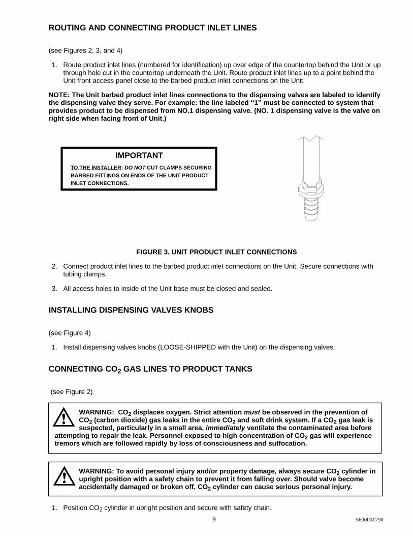
1. Route product inlet lines (numbered for identification) up over edge of the countertop behind the Unit or upthrough hole cut in the countertop underneath the Unit. Route product inlet lines up to a point behind theUnit front access panel close to the barbed product inlet connections on the Unit.
NOTE: The Unit barbed product inlet lines connections to the dispensing valves are labeled to identifythe dispensing valve they serve. For example: the line labeled ‘‘1’’must be connected to system thatprovides product to be dispensed from NO.1 dispensing valve. (NO. 1 dispensing valve is the valve onright side when facing front of Unit.)
IMPORTANTTO THE INSTALLER: DO NOT CUT CLAMPS SECURINGBARBED FITTINGS ON ENDS OF THE UNIT PRODUCTINLET CONNECTIONS.
FIGURE 3. UNIT PRODUCT INLET CONNECTIONS
2. Connect product inlet lines to the barbed product inlet connections on the Unit. Secure connections withtubing clamps.
3. All access holes to inside of the Unit base must be closed and sealed.
INSTALLING DISPENSING VALVES KNOBS
(see Figure 4)
1. Install dispensing valves knobs (LOOSE-SHIPPED with the Unit) on the dispensing valves.
CONNECTING CO2 GAS LINES TO PRODUCT TANKS
(see Figure 2)
WARNING: CO2 displaces oxygen. Strict attention must be observed in the prevention ofCO2 (carbon dioxide) gas leaks in the entire CO2 and soft drink system. If a CO2 gas leak issuspected, particularly in a small area, immediately ventilate the contaminated area before
attempting to repair the leak. Personnel exposed to high concentration of CO2 gas will experiencetremors which are followed rapidly by loss of consciousness and suffocation.
WARNING: To avoid personal injury and/or property damage, always secure CO2 cylinder inupright position with a safety chain to prevent it from falling over. Should valve becomeaccidentally damaged or broken off, CO2 cylinder can cause serious personal injury.
1. Position CO2 cylinder in upright position and secure with safety chain.

105600001790
2. Install primary CO2 regulator on CO2 cylinder. MAKE SURE NYLON WASHER IS INSIDE REGULATORASSEMBLY COUPLING NUT BEFORE CONNECTING TO CYLINDER.
3. Connect CO2 lines, with quick disconnects on their ends (not provided), to primary CO2 regulatorassembly. DO NOT CONNECT CO2 LINES TO PRODUCT TANKS AT THIS TIME.
PREPARING UNIT FOR OPERATION
CAUTION: Before opening CO2 cylinder shutoff valve, turn primary CO2 regulatorsadjusting screws to the left (counterclockwise) until all tension is relieved from adjustingscrews springs.
1. Open (counterclockwise) CO2 cylinder shutoff valve slightly to allow lines to slowly fill with gas, then openvalve fully to back-seat valve. (Back-seating valve prevents leakage around valve shaft.)
2. Adjust product tanks primary CO2 regulators pressure settings as instructed in SERVICE ANDMAINTENANCE section of this manual..
3. Connect CO2 and product lines to product tanks. Check for leaks and tighten loose connections.
UNIT OPERATION
1. Dispense from each dispensing valve until air is purged from systems and product is dispensed.
2. Check for leaks and tighten loose connections.
3. Adjust dispensing valves for dispensed product flow rate as instructed in SERVICE AND MAINTENANCEsection of this manual.
4. Install Unit front access panel and secure with screws.
5. Install hood on Unit and secure with screw. MAKE SURE HOOD GRILLE IS POSITIONED OVER THEREFRIGERATION CONDENSER COIL WHEN HOOD IS IN PLACE ON THE UNIT.
6. Install drip tray on the Unit, then install cup rest in the drip tray.

11 560001790
OPERATOR’S INSTRUCTIONS
This section covers operators instructions for operating controls, daily pre-operation check, adjustments,replenishing CO2 and product supplies, cleaning and sanitizing, checking drop-in refrigeration assemblycondenser coil for restrictions, and checking ice water bath.
WARNING: Disconnect electrical power to Unit to prevent personal injury before attemptingany internal maintenance. Only qualified personnel should service internal components orelectrical wiring.
CAUTION: Do not place or store anything on top of the Unit.
IMPORTANT: Only qualified personnel should service the internal components or electrical wiring.
OPERATING CONTROLS(see Figure 4)
DISPENSING VALVE
Place cup under dispensing valve nozzle. Pull dispensing valve knob forward until cup is full, of product thenrelease knob.
DAILY PRE-OPERATION CHECK7. Make sure primary CO2 regulator assembly 1800-psi gage indicator is not in shaded (‘‘change CO2
cylinder’’) portion of dial. If so, CO2 cylinder is almost empty and must be replaced as instructed inSERVICE AND MAINTENANCE section of this manual.
8. Sufficient product supply in all product tanks. If not, replenish product supply as instructed in SERVICEAND MAINTENANCE section of this manual.
9. Make sure drip tray is clean and clean cup rest is in place in drip tray.
UNIT OPERATIONPlace cup or glass under dispensing valve. Pull dispensing valve knob forward until cup or glass is full ofproduct, then release the knob.
ADJUSTMENTS
PRODUCT TANK CO2 REGULATORS
Product tank CO2 regulators should be periodically checked for proper pressure settings and if necessary,adjusted as instructed in SERVICE AND MAINTENANCE section of this manual.
ADJUSTING DISPENSED PRODUCT FLOW RATE
Product flow rate of dispensed product should be periodically checked and if necessary, adjusted as instructedin SERVICE AND MAINTENANCE section of this manual.

12560001790
REPLENISHING CO2 SUPPLY
WARNING: CO2 displaces oxygen. Strict attention must be observed in the prevention ofCO2 (carbon dioxide) gas leaks in the entire CO2 and soft drink system. If a CO2 gas leak issuspected, particularly in a small area, immediately ventilate the contaminated area before
attempting to repair the leak. Personnel exposed to high concentration of CO2 gas will experiencetremors which are followed rapidly by loss of consciousness and suffocation.
NOTE: When indicator on primary CO2 cylinder regulator assembly 1800-psi gage is in shaded(‘‘change CO2 cylinder’’) portion of the dial, CO2 cylinder is almost empty and should be changed.
CO2 supply should be checked daily and if necessary, replenished as instructed in SERVICE ANDMAINTENANCE section of this manual.
REPLENISHING PRODUCT SUPPLYProduct supply should be checked daily and if necessary, replenished as instructed in SERVICE ANDMAINTENANCE section of this manual.
CLEANING AND SANITIZING
DAILY CLEANING OF Unit
Daily cleaning of Unit should be performed at end of daily operation as instructed in SERVICE ANDMAINTENANCE section of this manual.
SANITIZING UNIT
The product systems should be sanitized as instructed every 90-days as instructed in SERVICE ANDMAINTENANCE section of this manual.The sanitizing procedure should be performed by a qualified ServicePerson.
CHECKING DROP-IN REFRIGERATION ASSEMBLY CONDENSER COILFOR RESTRICTIONS
CAUTION: The refrigeration assembly condenser coil must be cleaned every 30-days.Excessive accumulation of dust, lint, and grease on the condenser coil will restrict air flowthrough the coil and cause the refrigeration system to overheat. Operating the refrigeration
system in an overheated condition will eventually lead to compressor failure and will automaticallyvoid the factory warranty.
NOTE: Circulating air required to cool condenser coil is drawn in through grille on top of the hood andis exhausted out through louvers on sides and back of the hood. Restricting air in and out of Unit willdecrease its cooling efficiency.
Area on top of Unit hood must be kept free of obstructions at all times. Make sure nothing is stored on top ofhood. Cooling Unit condenser coil should be periodically cleaned every 30-days as instructed in SERVICE ANDMAINTENANCE section of this manual.

13 560001790
CHECKING ICE WATER BATHA ‘‘gurgle’’heard from the Unit indicates water level in water tank is low and more water should be added asinstructed for maximum product cooling. Refer to SERVICE AND MAINTENANCE section of this manual.
CLEANING CO2 GAS CHECK VALVES(see Figure 2 and 6)
The CO2 gas check valves must be inspected and serviced as instructed at least once a year under normalconditions and after any CO2 system servicing or disruption. Servicing of gas check valves should be performedby qualified personnel. Refer to SERVICE AND MAINTENANCE section of this manual.


14560001790
THIS PAGE LEFT BLANK INTENTIONALLY

15 560001790
SERVICE AND MAINTENANCE
This section describes the service and maintenance procedures to be performed on the Unit.
IMPORTANT: Only qualified personnel should service the internal components or electrical wiring.
DANGER: To avoid possible fatal electrical shock or serious injury to the operator, it ishighly recommended that a GFI (ground fault circuit interrupt) be installed in the electricalcircuit for the 60 Hz Units. It is required that an ELCB (earth leakage circuit breaker) be
installed in the electrical circuit for the 50 Hz Units.
WARNING: Disconnect electrical power from the Unit to prevent personal injury beforeattempting any internal maintenance. Only qualified personnel should service the internalcomponents or electrical wiring.
PREPARING UNIT FOR SHIPPING OR RELOCATING
CAUTION: The Unit is intended for indoor installation only. Do not install this Unit in anoutdoor environment which would expose it to the outside elements.
CAUTION: Before shipping, storing, or relocating this Unit, the product systems must besanitized and all sanitizing solution must be purged from the product systems. A freezingambient environment will cause residual water remaining inside the Unit to freeze resulting
in damage to internal components.
HOOD, FRONT ACCESS PANEL AND DRIP TRAY REMOVAL(see Figure 4)
HOOD REMOVAL
CAUTION: Do not place or store anything on top of the Unit.
Remove screw securing hood, then lift hood straight up off the Unit. Make sure grille on top of the hood ispositioned over the refrigeration condenser coil when re-installing the hood.
IMPORTANT: Circulating air, required to cool the refrigeration assembly condenser coil is drawn inthrough grille on top of the hood and is exhausted out through louvers on sides and back of the Unit.
FRONT ACCESS PANEL REMOVAL
Remove two screws securing the front access panel, then remove the panel.

16560001790
HOOD RETAININGSCREW
HOOD
FRONT ACCESSPANEL
FRONT ACCESSPANEL RETAINING
SCREW (2)
DROP-INREFRIGERATION ASS’Y
WATER TANKOVERFLOW TUBE
CONDENSERCOIL
AGITATORMOTOR
CONTROLBOX
DISPENSINGVALVE (5)
PRODUCT INLETTUBE (5)
WATER TANKDRAIN HOSEDRIP TRAY
CUP REST
INSULATION PAD
FIGURE 4. PARTS IDENTIFICATION (FIVE-FLAVOR UNIT SHOWN)

17 560001790
DRIP TRAY REMOVAL
CAUTION: Use extreme care when removing and installing the drip tray to prevent breakingoff plastic holding tabs on back of the tray.
Very carefully Lift drip tray up, then pull tray back to remove.
PERIODIC INSPECTION1. Clean the drop-in refrigeration assembly condenser coil every 30-days as instructed. Cleaning the
condenser coil should be performed by a qualified Service Person. DO NOT place objects on top of thehood or on back side of the Unit. Restricting circulating air in and out of the Unit will cause the refrigerationsystem to overheat.
2. Check the dispensing valves for dripping that indicates leakage and repair as necessary.
ADJUSTMENTS
ADJUSTING PRODUCT TANKS CO2 REGULATORS
WARNING: CO2 displaces oxygen. Strict attention must be observed in the prevention ofCO2 (carbon dioxide) gas leaks in the entire CO2 and soft drink system. If a CO2 gas leak issuspected, particularly in a small area, immediately ventilate the contaminated area before
attempting to repair the leak. Personnel exposed to high concentration of CO2 gas will experiencetremors which are followed rapidly by loss of consciousness and suffocation.
(see Figure 2)
Set product tanks CO2 regulators, using Cornelius PRE-MIX COMPUTER slide rule or bottling room chart, atequilibrium pressure for highest temperature encountered between product tank storage area and Unit plus5-psig operating pressure for lines 10-feet in length or less and no vertical lift. Add one pound for every 10-feetover initial 10-feet of product tank to Unit line length and one pound for every 2-feet of vertical lift. Add onepound for every product tank on line over three tanks.
ADJUSTING DISPENSED PRODUCT FLOW RATE
(see Figure 5)
Rotate dispensing valve Compensator Adjusting Screw to the left (counterclockwise) for higher product flow rateor to the right (clockwise) for lower product flow rate.
CLEANING AND SANITIZING
DAILY CLEANING OF UNIT EXTERIOR
1. Remove cup rest and drip tray from the Unit.
2. Wash cup rest and drip tray, then rinse them with warm water.
3. Re-install cup rest and drip tray on the Unit.

18560001790
4. Rinse out sponge with clean water, then wring excess water out of sponge and wipe off all externalsurfaces of Unit. Wipe Unit dry with a clean soft cloth. DO NOT USE ABRASIVE TYPE CLEANERS.
WEEKLY CLEANING OF DISPENSING VALVES(see Figure 5)
Dispensing valves should be cleaned at least weekly for proper operation. A convenient time to cleandispensing valves is at time unit is being sanitized. Perform following procedure to clean dispensing valves.
1. Remove quick disconnects (black) from product tanks outlets.
2. Open dispensing valves to relieve pressure on systems.
3. Remove dispensing valve knobs by pulling knobs up and off valves.
4. Using a spanner wrench, loosen and remove coupling nuts from dispensing valves, then remove valvesfrom unit.
5. Remove phillips-head screw on end of dispensing valve, then remove outer sleeve, spring, and innersleeve.
6. Loosen and remove knob lever bonnet securing lever in dispensing valve body, then remove lever.
7. Slide shaft and seat assembly out through rear of dispensing valve body.
8. Wash disassembled dispensing valve parts in warm potable water.
9. Assemble dispensing valve by reversing disassembly procedure steps 5 through 7 preceding.
10. Disassemble and clean remaining dispensing valve by performing steps 5 through 9 preceding.
11. Remove compensators from inside sleeve and coupling nut assemblies.
12. Wash compensators in warm potable water, then install compensators in sleeve and coupling nutassemblies.
13. Install dispensing valves on unit. Make sure coupling nuts are tight.
14. Install quick disconnects on product tanks outlets.
15. Open dispensing valves to bleed air from systems and until product flows from valves.
SANITIZING UNIT
NOTE: An alternate to the preferred sanitizing procedure outlined below would be to removedispensing valves, then make necessary connections to circulate sanitizing solution through theproduct systems. After systems have been sanitized, dispensing valves may then be disassembled (seeFigure 5) and cleaned before re-installing on Unit.
IMPORTANT: Only qualified personnel should perform sanitizing procedure.
The product systems should be sanitized every 90-days following Sanitizer Manufacturer’s recommendations.Use Chlor-Tergent (Oakite Products, Inc.) or equivalent sanitizer.
1. Remove quick disconnects from product tanks, then rinse quick disconnects in warm water.
2. Using clean empty product tank, prepare full tank of sanitizing solution by using 70°F to 100°F (max) plainwater and .67 oz./gallon of sanitizer. This mixture will provide 200-ppm of chlorine.
3. Shake sanitizing solution tank to thoroughly mix solution, then connect tank into system to be sanitized.
4. Place waste container under applicable dispensing valve. Open dispensing valve to permit sanitizingsolution to purge product out of system and valve. Continue to draw from dispensing valve until onlysanitizing solution is dispensed, then close valve.

19 560001790
5. Repeat steps 3 and 4 preceding to purge product from and install sanitizing solution in remaining systems.
CAUTION: Do not allow sanitizing solution to remain in systems longer than recommendedcontact time. Exceeding contact time will result in damage to stainless steel components.
KNOB
BALL WASHER
LEVER
COMPENSATOR ADJUSTING SCREW
SPRING SHAFT AND SEAT ASS’Y
BODY
INNER SLEEVE
OUTER SLEEVE
PHILLIP-HEADSCREW
FRICTION WASHER
COMPENSATOR
O-RING
O-RING
KNOB LEVER BONNET
FIGURE 5. DISPENSING VALVE PARTS IDENTIFICATION
6. Allow sanitizing solution to remain in systems for not less than 10 or no more than 15 minutes (max)contact time.
7. Remove tank containing sanitizing solution from system, then connect tanks containing product intosystems.
WARNING: Flush sanitizing solution from systems as instructed. Residual sanitizingsolution left in systems could create a health hazard.
8. Place waste container under dispensing valve. Open dispensing valve to permit product to purge sanitizingsolution from system and dispensing valve. Continue to draw from valve until only product is dispensedfrom system, then close valve.
9. Repeat step 8 to purge sanitizing solution out of remaining systems and until only product is dispensed.
WARNING: To avoid possible personal injury or property damage, do not attempt toremove product tank cover until CO2 pressure has been released from tank.
10. Thoroughly rinse inside and outside of product tank that was used for sanitizing solution to remove allsolution residue.
11. Clean exterior of Unit as instructed in DAILY CLEANING OF UNIT.

20560001790
CLEANING DROP-IN REFRIGERATION ASSEMBLY CONDENSER COIL(see Figure 4)
CAUTION: The refrigeration assembly condenser coil must be cleaned every 30-days.Excessive accumulation of dust, lint, and grease on the condenser coil will restrict air flowthrough the coil and cause the refrigeration system to overheat. Operating the refrigeration
system in an overheated condition will eventually lead to compressor failure and will automaticallyvoid the factory warranty.
Clean the drop-in refrigeration assembly coil as follows:
1. Unplug Unit power cord from the electrical outlet.
2. Remove screw securing the hood, then lift the hood straight up to remove.
3. Vacuum or use a soft brush to clean the condenser coil. If available, use low-pressure compressed air.
4. Clean dust and dirt from around top of the drop-in refrigeration assembly.
5. Install hood on the Unit and secure with screw.
6. Plug Unit power cord into electrical outlet. The refrigeration system will start after a 2-minute time delay.
CHECKING ICE WATER BATH(see Figure 4)
A ‘‘gurgle’’heard from the Unit indicates water level in the water tank is low and more water should be added formaximum cooling. Before adding more water, check the ice water bath for cleanliness and check the water tankcoils for excessive mineral deposit build-up.
1. Unplug Unit power cord from electrical outlet.
2. Remove screw securing the hood, then lift the hood straight up to remove.
3. Lift insulation pad covering front section of the water tank for visual inspection of the ice water bath andthe ice bank.
4. Using a flashlight, inspect the ice water bath and ice bank for cleanliness. The ice water bath should beclear and the ice bank should be free of foreign particles.
5. If cleaning of the water tank is necessary, refer to CLEANING WATER TANK in this section.
6. Fill the water tank with clean water until water begins to run out of the overflow tube into the drip tray. USELOW-MINERAL-CONTENT WATER WHERE A LOCAL WATER PROBLEM EXISTS.
7. Lower the insulation pad into proper position on top of the water tank.
8. Install Unit hood and secure with screw.
9. Plug Unit power cord into electrical outlet. The refrigeration system will start after a 2-minute time delay.
CLEANING WATER TANK(see Figure 4)
1. Unplug the Unit power cord from electrical outlet.
2. Remove two screws securing the Unit front access panel, then remove the panel.
3. Extend the water tank drain hose (located on front of Unit) to a waste container or floor drain. Remove plugfrom end of the drain hose and allow the water tank to drain.

21 560001790
4. Remove screw securing the hood, then lift the hood straight up to remove from the Unit.
CAUTION: The ice bank around the drop-in refrigeration assembly evaporator coils must becompletely melted before attempting to lift the drop-in refrigeration assembly up and out ofthe Unit lower cabinet assembly. Attempting to lift the drop-in refrigeration assembly and
ice bank together up out of the Unit lower housing assembly may cause damage to the evaporatorcoils.
CAUTION: Never use an ice pick or other instrument to remove ice from the drop-inrefrigeration assembly evaporator coils. Such practice can result in a puncturedrefrigeration circuit.
5. Allow the ice bank around the drop-in refrigeration assembly evaporator coils to completely melt. Hot watermay be used to speed up the melting process.
6. Remove four screws securing the drop-in refrigeration assembly in the Unit lower housing assembly.
7. Very carefully, lift the drop-in refrigeration assembly up and out of the Unit lower housing assembly.
8. Use a fiber brush and carefully clean mineral deposit build-up from the agitator motor shaft and the icebank sensor.
9. Wash inside of the water tank and the drop-in refrigeration assembly evaporator coils, then rinse with cleanwater.
10. Install plug in end of the water tank drain hose.
11. Very carefully, install drop-in refrigeration assembly in Unit lower housing assembly by reversing theremoval procedure.
12. Fill the water tank with clean water until water runs out of the water tank overflow hose. USELOW-MINERAL-CONTENT WATER WHERE A LOCAL WATER PROBLEM EXISTS.
13. Plug Unit power cord into electrical outlet. The refrigeration system will start after a 2-minute time delay.
14. Install Unit hood and secure with screw.
15. Install Unit front access panel and secure with two screws.
REPLENISHING CO2 SUPPLY
WARNING: CO2 displaces oxygen. Strict attention must be observed in the prevention ofCO2 (carbon dioxide) gas leaks in the entire CO2 and soft drink system. If a CO2 gas leak issuspected, particularly in a small area, immediately ventilate the contaminated area before
attempting to repair the leak. Personnel exposed to high concentration of CO2 gas will experiencetremors which are followed rapidly by loss of consciousness and suffocation.
NOTE: When indicator on CO2 cylinder primary CO2 regulator assembly 1800-psi gage is in shaded(‘‘change CO2 cylinder’’) portion of dial, CO2 cylinder is almost empty and should be changed.
1. Fully close (clockwise) CO2 cylinder valve.
2. Slowly loosen primary CO2 regulator assembly coupling nut allowing CO2 pressure to escape, then removeregulator assembly from empty CO2 cylinder.
3. Unfasten safety chain and remove empty CO2 cylinder.
WARNING: To avoid personal injury and/or property damage, always secure CO2 cylinder inupright position with safety chain to prevent it from falling over. Should valve become

22560001790
4. Position CO2 cylinder and secure with safety chain.
5. Make sure gasket is in place inside primary CO2 regulator coupling nut, then install regulator on CO2cylinder.
6. Open (counterclockwise) CO2 cylinder valve slightly to allow lines to slowly fill with gas, then open valvefully to back-seat valve. (Back-seating valve prevents leakage around valve shaft).
REPLENISHING PRODUCT SUPPLY
NOTE: The following instructions are applicable only when replenishing with the same flavor product.Refer to PRODUCT FLAVOR CHANGE when changing product flavor.
1. Disconnect empty product tank from product system.
2. Check product tank quick disconnects for sticky or restricted operation. Wash disconnects in warm water.
3. Connect full tank of product into syrup system.
PRODUCT FLAVOR CHANGE
1. Perform sanitizing procedure on product system product flavor change will be made on.
2. Check product tank quick disconnects for sticky or restricted operation. Wash disconnects in warm water.
3. Connect full tank of new flavor product into product system.
CLEANING CO2 SYSTEM CO2 GAS CHECK VALVES
(see Figures 2 and 6 )
The CO2 regulators and CO2 manifold CO2 gas check valves must be inspected and serviced at least once ayear under normal conditions and after any servicing or disruption of the CO2 system. ALWAYS REPLACEBALL SEAT (QUAD RING SEAL) EACH TIME GAS CHECK VALVES ARE SERVICED.
*Quad ring seal must be replaced eachtime check valve is serviced.
BODY183295000
RETAINER183298000
BALL183296000
*QUAD RING183294000
SPRING183297000
FIGURE 6. CO2 GAS CHECK VALVE

23 560001790
FIGURE 7. WIRING DIAGRAM


24560001790
THIS PAGE LEFT BLANK INTENTIONALLY

25 560001790
WARNING: If repairs are to be made to a product system, remove quick disconnects fromthe applicable product tank, then relieve the system pressure before proceeding. If repairsare to be made to the CO2 system, stop dispensing, shut off the CO2 supply, then relieve the
system pressure before proceeding. If repairs are to be made to the refrigeration system, make sureelectrical power is disconnected from the unit.
TROUBLESHOOTING
IMPORTANT: Only qualified personnel should service internal components or electrical wiring.
Trouble Probable Cause Remedy
TROUBLESHOOTING DISPENSING SYSTEM
NO PRODUCT DISPENSED. A. Product tank quick dis-connects not connected.
A. Connect quick disconnects.
B. No product supply (tankempty).
B. Replenish product supply asinstructed.
C. No CO2 supply. C. Replenish CO2 supply asinstructed.
DISPENSED PRODUCTCOMES OUT OF DISPENS-ING VALVE CLEAR BUTFOAMS IN CUP.
A. Oil film or soap scum in cups. A. Use clean cups.
B. Ice used for finished drink issub-cooled.
B. Do not use ice directly fromfreezer. Allow ice to become ‘‘wet’’before using. (Refer to followingNOTE)
NOTE: Crushed ice also causes dispensing problems. When finished drink hits sharp edges of ice,carbonation is released from dispensed drink.
DISPENSED PRODUCTFOAMS AS IT LEAVESDISPENSING VALVE.
A. Recovery rate of dispenserexceeded, ice bank depleted.
A. Allow ice bank to recover.
B. Product tanks CO2 regulatoradjusted too high.
B. Adjust product tanks CO2regulator pressure as instructed.
C. Dispensing valve restricted ordirty.
C. Sanitize system.
D. Tapered gasket inside tubeswivel nut connection distortedfrom being overtightenedrestricting product flow.
D. Replace tapered gasket. Makesure gasket is properly seated.
E. Oil, water, or dirt in CO2supply.
E. Remove contaminated CO2.Clean CO2 system (lines,regulators, etc.). Install a cleanCO2 supply.

26560001790
Trouble RemedyProbable Cause
TROUBLESHOOTING REFRIGERATION SYSTEM
COMPRESSOR DOES NOTOPERATE.
A. Ice bank sufficient. A. Refrigeration not called for.
B. Unit power cord unplugged. B. Plug in Unit power cord.
C. No power source (blown fuse)or tripped circuit breaker.
C. Replace fuse or reset circuitbreaker. (Note: Fuse is not part ofUnit)
D. Low voltage. D. Correct low voltage condition.
E. Loose, disconnected, orbroken wiring.
E. Tighten connections or replacebroken wiring.
F. Overload protector cut out;over-heated compressor.Condenser fan motor notoperating as required.
F. Compressor will cool enough torestart. Do not overdraw coolingcapacity of dispenser. Refer to‘‘CONDENSER FAN MOTORNOT OPERATING’’in thissection.
G. Inoperative overload protectoror start relay.
G. Replace inoperative part.
H. Inoperative ice bank control. H. Replace ice bank control.
I. Inoperative compressor. I. Replace compressor.
COMPRESSOR OPERATESCONTINUOUSLY BUT DOESNOT FORM SUFFICIENT ICEBANK.
A. Cooling capacity is exceededby over-drawing.
A. Reduce amount of drinks drawnper given time.
B. Unit located in excessively hotarea or air circulation throughcondenser coil is restricted.
B. Relocate Unit or clean condensercoil as instructed.
C. Refrigeration system leak. C. Call refrigeration repairman.
NOTE: Ice bank freezes from bottom of evaporator upward. A refrigerant leak or insufficient chargemight show ice bank at bottom and not at top of evaporator.
NOTE: If overload protector cuts out compressor, condenser fan motor will continue to run; otherwise;troubleshooting condenser fan motor problems is same as for ‘‘COMPRESSOR DOES NOT OPERATE’’paragraph plus the following:
CONDENSER FAN MOTORNOT OPERATING.
A. Jumper cord loose ordisconnected from motor orterminal block. Broken wire incord.
A. Tighten connections or replacecord.
B. Fan blade obstructed. B. Remove obstruction.
C. Inoperative condenser fanmotor.
C. Replace condenser fan motor.
AGITATOR MOTOR NOTOPERATING.
A. Unit power cord unplugged. A. Plug in Unit power cord.
B. No power source (blown fuse)or tripped circuit breaker.
B. Replace fuse or reset circuitbreaker. (Note: Fuse is not part ofUnit)
C. Agitator motor propellerobstructed.
C. Remove obstructions.

27 560001790
Trouble RemedyProbable Cause
AGITATOR MOTOR NOTOPERATING (Cont’d)
D. Low voltage. D. Correct low voltage condition.
E. Loose, disconnected, orbroken wiring.
E. Tighten connections or replacebroken wiring.
F. Inoperative agitator motor. F. Replace agitator motor.

560001790 28
WARRANTY
IMI Cornelius Inc. warrants that all equipment and parts are free from defects in material and workmanship un-der normal use and service. For a copy of the warranty applicable to your Cornelius, Remcor or Wilshire prod-uct, in your country, please write, fax or telephone the IMI Cornelius office nearest you. Please provide theequipment model number, serial number and the date of purchase.
IMI Cornelius Offices
AUSTRALIA D P.O. 210, D RIVERWOOD, D NSW 2210, AUSTRALIA D (61) 2 533 3122 D FAX (61) 2 534 2166AUSTRIA D AM LANGEN FELDE 32 D A-1222 D VIENNA, AUSTRIA D (43) 1 233 520 D FAX (43) 1-2335-2930BELGIUM D BOSKAPELLEI 122 D B-2930 BRAASCHAAT, BELGIUM D (32) 3 664 0552 D FAX (32) 3 665 2307BRAZIL D RUA ITAOCARA 97 D TOMAS COELHO D RIO DE JANEIRO, BRAZIL D (55) 21 591 7150 D FAX (55) 21 593 1829ENGLAND D TYTHING ROAD ALCESTER D WARWICKSHIRE, B49 6 EU, ENGLAND D (44) 789 763 101 D FAX (44) 789 763 644FRANCE D 71 ROUTE DE ST. DENIS D F-95170 DEUIL LA BARRE D PARIS, FRANCE D (33) 1 34 28 6200 D FAX (33) 1 34 28 6201GERMANY D CARL LEVERKUS STRASSE 15 D D-4018 LANGENFELD, GERMANY D (49) 2173 7930 D FAX (49) 2173 77 438GREECE D 488 MESSOGION AVENUE D AGIA PARASKEVI D 153 42 D ATHENS, GREECE D (30) 1 600 1073 D FAX (30) 1 601 2491HONG KONG D 1104 TAIKOTSUI CENTRE D 11-15 KOK CHEUNG ST D TAIKOKTSUE, HONG KONG D (852) 789 9882 D FAX (852) 391 6222ITALY D VIA PELLIZZARI 11 D 1-20059 D VIMARCATE, ITALY D (39) 39 608 0817 D FAX (39) 39 608 0814NEW ZEALAND D 20 LANSFORD CRES. D P.O. BOX 19-044 AVONDALE D AUCKLAND 7, NEW ZEALAND D (64) 9 8200 357 D FAX (64) 9 8200 361SINGAPORE D 16 TUAS STREET D SINGAPORE 2263 D (65) 862 5542 D FAX (65) 862 5604SPAIN D POLIGONO INDUSTRAIL D RIERA DEL FONOLLAR D E-08830 SANT BOI DE LLOBREGAT D BARCELONA, SPAIN D (34) 3 640 2839 D FAX (34) 3 654 3379USA D ONE CORNELIUS PLACE D ANOKA, MINNESOTA D (612) 421-6120 D FAX (612) 422-3255
LD0044/21/98

29 560001790
THIS PAGE LEFT BLANK INTENTIONALLY

IMI CORNELIUS INC.
CORPORATE HEADQUARTERS:
One Cornelius PlaceAnoka, Minnesota 55303-6234(612) 421-6120(800) 238-3600