Embed Size (px)
Citation preview

Installation Manual
TerraGen Environmental Group
51b Caldari Road, Unit 16
Concord, Ontario, L4K 4G3
905-760-1000
Last updated: 23/03/2016

TGR Ballasted System 1
Table of Contents
1. General ........................................................................................................................................ 2
2. Material Receiving ...................................................................................................................... 2
3. Ballast Requirements .................................................................................................................. 2
4. Materials and Tools Required ..................................................................................................... 2
5. System Components ................................................................................................................... 3
6. Installation of System .................................................................................................................. 4
6.1. Locate Starting Points and Placement of First Base Rail. ..................................................... 4
6.2. Rubber Placement. ............................................................................................................... 4
6.3. Base Rail Placement. ............................................................................................................ 5
6.4. Tilt Triangle Installation. ....................................................................................................... 5
6.5. Top Rail Installation. ............................................................................................................. 6
6.6. Splicing Top Rails. ................................................................................................................. 6
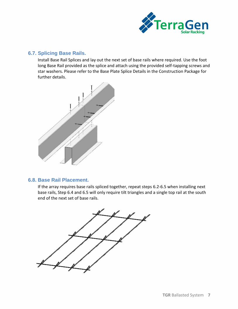
6.7. Splicing Base Rails. ................................................................................................................ 7
6.8. Base Rail Placement. ............................................................................................................ 7
6.9. Remaining Tilt Triangle Installation. ..................................................................................... 8
6.10. Verify the Rubber Placement. ............................................................................................ 8
6.12. Ballast Placement. .............................................................................................................. 8
6.13. Remaining Top Rail Installation. ......................................................................................... 9
6.14. Home Run Wiring: .............................................................................................................. 9
6.15. Thermal Break Note for Top Rails: ..................................................................................... 9
6.16. Module Installation. ......................................................................................................... 10
6.17. Bonding Note:................................................................................................................... 11

TGR Ballasted System 2
1. General
The TGR Ballasted System is design to be installed on a flat or low sloping roof, and is design to
withstand all natural forces and loads when properly installed. To ensure a proper installation
and avoid a void of warranty the installation manual must be followed.
2. Material Receiving
A detailed Bill of Lading will be sent with the shipment of racking. The receiver must confirm
that all parts received are according to the detailed Bill of Lading and Packing Slip. Any damages
must be noted on the bill of lading upon receipt. Any discrepancies must be reported within 2
business days. Otherwise all claims will be invalid. If any there are any damaged parts or rails,
please provide a picture as well as documenting it on the Bill of Lading.
3. Ballast Requirements
The TGR Ballasted System has been designed utilizing 30 lbs, 15 3/8” x 7 1/2” x 3 1/2” concrete
blocks in Canada and 33 lbs, 15 9/16”x 7 1/2” x 3 5/8”. Provided components are design to
these dimensions, and any discrepancy with the block size will alter the function of these
components. Refer to the Construction Package for ballast quantity and placement.
4. Materials and Tools Required
- Open ended wrench 13 mm
- 13 mm deep sockets
- 5/16 socket
- Metric Allen Key or Driver 5 mm and 6 mm
- Measuring Tape
- 7 ft/lbs torque wrench
- 12 ft/lbs torque wrench
- Cordless screwdriver
- String Line
- Onsite cutting ability
TGR Ballasted System 3
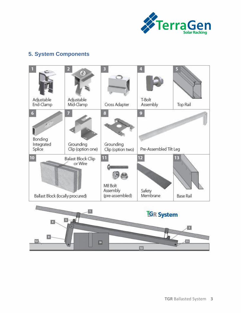
5. System Components

TGR Ballasted System 4
6. Installation of System
6.1. Locate Starting Points and Placement of First Base Rail.
Measure and mark the starting points according to the layout plan. The first Base Rail will be used as the starting reference point. Place all base rails such that N dimension is larger than the S dimension and on the NORTH side.
Base Rail side View
Base Rail Starting Layout Plan View
6.2. Rubber Placement.
Rubber is to protect the roof deck and roof membrane. Place rubber underneath the Base rails before the placement of the rail, place inside all tilt triangle areas and also make sure there is rubber underneath all the end cuts of rails (expose at least 3 inches of rubber at the end of every rail) and center a piece of rubber where the base rail splice will be.

TGR Ballasted System 5
6.3. Base Rail Placement.
Place the second Base Rail using a spacing jig or measuring tape, place the rest of the Base Rails across the array(East-West). Ensure spacing the proper distance apart E-W and make sure that they have the same starting point N-S. A string line or laser line can help with finding the proper starting point N-S.
Refer to Construction Package for dimension d.
6.4. Tilt Triangle Installation.
- Assemble the tilt triangles onto the Base rails using the M8- 50 mm bolt through the pre-drilled holes and securing with the M8 serrated nut. Start with installing one tilt triangle at the north and south of every base rail that has been laid out. Each bolt shall be torqued to 7 ft/lbs.

TGR Ballasted System 6
6.5. Top Rail Installation.
Use Cross-Adapters for installing the top rails, click the cross adapter onto the tilt triangle to attach a top rail across the one row of tilt triangles on the north row, this will help finalize the spacing and stabilize the base rails. Attach a top rail to the south row as well. It is important to find the correct point on the tilt triangle where the top rail will be installed. Refer to the construction details and be sure not to over-hang the top rail more than 23 inches past the tilt triangle.
Note: Do NOT Exceed a 23” Overhang.
6.6. Splicing Top Rails.
When required, the top rails get spliced together with a bonding integrated splice bar. Ensure that the rivet is exposed and that the grounding weeb is engaged with the aluminum from both rails. Where thermal breaks are required, a ¾” gap must be maintained between the ends of the Top Rails.
TGR Ballasted System 7
6.7. Splicing Base Rails.
Install Base Rail Splices and lay out the next set of base rails where required. Use the foot long Base Rail provided as the splice and attach using the provided self-tapping screws and star washers. Please refer to the Base Plate Splice Details in the Construction Package for further details.
6.8. Base Rail Placement.
If the array requires base rails spliced together, repeat steps 6.2-6.5 when installing next base rails, Step 6.4 and 6.5 will only require tilt triangles and a single top rail at the south end of the next set of base rails.

TGR Ballasted System 8
6.9. Remaining Tilt Triangle Installation.
Finalize assembly of all triangles onto the base rails. Refer to step 6.4.
6.10. Verify the Rubber Placement.
Make sure that rubber is in proper positions for ballast placement and that all ends and splices have rubber underneath.
6.12. Ballast Placement.
Place ballast in areas where required according to the ballast plan located in the Construction Package and secure blocks with the provided ballast clip or threaded rod where ballast are drilled. Please refer to the ballast block drawing for further information located in the Construction Package.

TGR Ballasted System 9
6.13. Remaining Top Rail Installation.
Install the remaining of the top rails. Hand tighten fasteners first, then torque all fasteners to 7 ft. /lbs. Make sure that all M8 bolts and cross adapters are torqued before the modules are installed.
6.14. Home Run Wiring:
After top rail installation is complete, this would be the best time to run all PV Cable and home runs as this allows the installer to have free range of access to the racking for securing the PV Cable.
6.15. Thermal Break Note for Top Rails:
If the length of a top rail exceeds 40 ft., then the module field needs to be divided by two End-Clamps and a splice. Allow for a ¾” gap.

TGR Ballasted System 10
6.16. Module Installation.
Install the modules by first clicking the end clamps onto the end of the top rails. Adjust the module to the proper position and tighten the end clamps to 7 ft./lbs. Now click the mid clamps with the grounding clip (refer to bonding note and drawings) onto the top rail. Slide the mid-clamp in tight to the module making sure that the tab of the ground clip or weeb is placed under the module frame. Once the next module is placed properly, the mid clamp can then be secured and torqued to 12 ft./lbs. In the circumstance where the modules being installed have 50mm frames, care needs to be taken when installing mid clamps and end clamps as the bolt will be on its last few threads. Hand loosen the bolt prior to installing on rail.

TGR Ballasted System 11
6.17. Bonding Note:
Grounding clips or weeb clips are typically needed with every other mid-clamp along the top rail. Every panel must have at least two points where the panel creates a bond through a ground clip or weeb.
X= Weeb Location
X= Weeb Location
TerraGen Environmental Group Inc.
51b Caldari Road, Unit 16
Concord, ON L4K 4G3
Tel: 905-760-1000
Fax: 905-760-1099
www.terragensolar.ca