Embed Size (px)
Citation preview

Please read this manual before connecting the Advanced Hybrid System.
Model No. KX-TA624
Advanced Hybrid System
Installation Manual

2
System Components
Thank you for purchasing this Panasonic Model KX-TA624, Advanced Hybrid System.
KX-T30865KX-T30890KX-T7090
OptionalEquipment
DoorphoneHeadset (Earphone type)Headset (Headphone type)
System Components Table
Model Description
Service Unit
Telephone
KX-TA624 Advanced Hybrid System (Main Unit)
Proprietary telephone with displayProprietary telephoneProprietary telephone with displayProprietary telephoneProprietary telephone
Doorphone/Door Opener Card8 Extension Expansion Card3 CO Line and 8 EXT Expansion CardOGM/FAX Detection CardCaller ID Card
KX-T7130KX-T7020KX-T7030KX-T7050KX-T7055
KX-TA62460KX-TA62470KX-TA62477KX-TA62491KX-TA62493

3
Attention
• Keep the unit away from heating appliances and electrical noise generating devices such asfluorescent lamps, motors and televisions. These noise sources can interfere with theperformance of the Advanced Hybrid System.
• This unit should be kept free of dust, moisture, high temperature (more than 40 ˚C 104 ˚F)and vibration, and should not be exposed to direct sunlight.
• Never attempt to insert wires, pins, etc. into the vents or other holes of this unit.• If there is any trouble, disconnect the unit from the telephone line. Plug the telephonedirectly into the telephone line. If the telephone operates properly, do not reconnect the unitto the line until the trouble has been repaired. If the telephone does not operate properly,chances are that the trouble is in the telephone system, and not in the unit.
• Do not use benzine, thinner, or the like, or any abrasive powder to clean the cabinet. Wipe itwith a soft cloth.
The serial number of this product may be found on the label affixed to the side of theunit. You should note the model number and the serial number of this unit in the spaceprovided and retain this book as a permanent record of your purchase to aid inidentification in the event of theft.
MODEL NO.:
SERIAL NO.:
WARNING
THIS UNIT MAY ONLY BE INSTALLED AND SERVICED BY QUALIFIEDSERVICE PERSONNEL.
WHEN A FAILURE OCCURS WHICH RESULTS IN THE INTERNAL PARTSBECOMING ACCESSIBLE, DISCONNECT THE POWER SUPPLY CORDIMMEDIATELY AND RETURN THIS UNIT TO YOUR DEALER.
DISCONNECT THE TELECOM CONNECTION BEFORE DISCONNECTINGTHE POWER CONNECTION PRIOR TO RELOCATING THE EQUIPMENT, ANDRECONNECT THE POWER FIRST.
THIS UNIT IS EQUIPPED WITH AN EARTHING CONTACT PLUG. FORSAFETY REASONS THIS PLUG MUST ONLY BE CONNECTED TO ANEARTHING CONTACT SOCKET WHICH HAS BEEN INSTALLED ACCORDINGTO REGULATIONS.
THE POWER SUPPLY CORD IS USED AS THE MAIN DISCONNECT DEVICE,ENSURE THAT THE SOCKET-OUTLET IS LOCATED/INSTALLED NEAR THEEQUIPMENT AND IS EASILY ACCESSIBLE.
TO PREVENT FIRE OR SHOCK HAZARD, DO NOT EXPOSE THIS PRODUCTTO RAIN OR MOISTURE.

4
Attention
DATE OF PURCHASE
NAME OF DEALER
DEALER’S ADDRESS
DEALER’S TEL NO.
When you ship the productCarefully pack and send it prepaid, adequately insured and preferably in the original carton.Attach a postage-paid letter, detailing the symptom, to the outside of the carton. DO NOTsend the product to the Executive or Regional Sales offices. They are NOT equipped to makerepairs.
Product servicePanasonic Factory Servicenters for this product are listed in the servicenter directory.Consult your authorized Panasonic dealer for detailed instructions.
For your future reference

5
Important Safety Instructions
When using your telephone equipment, basic safety precautions shouldalways be followed to reduce the risk of fire, electric shock and injury topersons, including the following:
1. Read and understand all instructions.
2. Follow all warnings and instructions marked on the product.
3. Unplug this product from the wall outlet before cleaning. Do not useliquid cleaners or aerosol cleaners. Use a damp cloth for cleaning.
4. Do not use this product near water, for example, near a bathtub, washbowl, kitchen sink, or laundry tub, in a wet basement, or near aswimming pool.
5. Do not place this product on an unstable cart, stand, or table. Theproduct may fall, causing serious damage to the product.
6. Slots and openings in the cabinet and the back or bottom are providedfor ventilation, to protect it from overheating, these openings must notbe blocked or covered. The openings should never be blocked byplacing the product on the bed, sofa, rug, or other similar surface. Thisproduct should never be placed near or over a radiator or heat register.This product should not be placed in a built-in installation unlessproper ventilation is provided.
7. This product should be operated only from the type of power sourceindicated on the marking label. If you are not sure of the type of powersupply to your home, consult your dealer or local power company.
8. This product is equipped with a three wire grounding type plug, a plughaving a third (grounding) pin. This plug will only fit into a groundingtype power outlet. This is a safety feature. If you are unable to insertthe plug into the outlet, contact your electrician to replace yourobsolete outlet. Do not defeat the safety purpose of the grounding typeplug.
9. Do not allow anything to rest on the power cord. Do not locate thisproduct where the cord will be abused by people walking on it.
10. Do not overload wall outlets and extension cords as this can result inthe risk of fire or electric shock.

6
Important Safety Instructions
11. Never push objects of any kind into this product through cabinet slotsas they may touch dangerous voltage points or short out parts thatcould result in a risk of fire or electric shock. Never spill liquid of anykind on the product.
12. To reduce the risk of electric shock, do not disassemble this product,but take it to a qualified serviceman when some service or repair workis required. Opening or removing covers may expose you to dangerousvoltages or other risks. Incorrect reassembly can cause electric shockwhen the appliance is subsequently used.
13. Unplug this product from the wall outlet and refer servicing to qualifiedservice personnel under the following conditions:
A. When the power supply cord or plug is damaged or frayed.
B. If liquid has been spilled into the product.
C. If the product has been exposed to rain or water.
D. If the product does not operate normally by following the operatinginstructions. Adjust only those controls, that are covered by theoperating instructions because improper adjustment of othercontrols may result in damage and will often require extensive workby a qualified technician to restore the product to normal operation.
E. If the product has been dropped or the cabinet has been damaged.
F. If the product exhibits a distinct change in performance.
14. Avoid using a telephone (other than a cordless type) during anelectrical storm. There may be a remote risk of electric shock fromlightning.
15. Do not use the telephone to report a gas leak in the vicinity of the leak.
SAVE THESE INSTRUCTIONS

7
Telephone Company and F.C.C. Requirements and Responsibilities
1. Notification to the Telephone CompanyCustomers, before connecting terminal equipment to the telephone network, shall upon request of theTelephone Company, inform the Telephone Company of the particular line(s) to which suchconnection is made, the F.C.C. registration number (see the label on the bottom of the unit) andringer equivalence number (REN) of the registered terminal equipment.The REN is useful in determining the quantity of devices you may connect to your telephone line andstill have all of those devices ring when your telephone number is called. In most, but not all areas,the sum of the REN’s of all devices connected to one line should not exceed five (5.0). To be certainof the number of devices you may connect to your line, as determined by the REN, you shouldcontact your local telephone company to determine the maximum REN for your calling area.
2. Connection to Telephone LineThis unit must not be connected to a coin operated line. If you are on a party line, check with yourlocal telephone company.
3. Incidence of Harm to the Telephone LinesShould terminal equipment cause harm to the telephone network, the telephone company shall,where practical, notify the customer that temporary discontinuance of service may be required.However, where prior notice is not practical, the telephone company may temporarily discontinueservice forthwith, if such action is reasonable in the circumstances. In case of such unnotifiedtemporary discontinuance of service, the telephone company shall:
(a) Promptly notify the customer of such temporary discontinuance of service.(b) Afford the customer the opportunity to correct the situation which gave rise to the temporary
discontinuance.(c) Inform the customer of the right to bring a complaint to the Federal Communication
Commission pursuant to the procedures set out in Subpart E of Part 68 of FCC TelephoneEquipment Rules.
4. Compatibility of the Telephone Network and Terminal Equipment(a) Availability of telephone interface information.
Technical information concerning interface parameters and specifications not specified in FCC Rules,including the number of Ringers which may be connected to a particular telephone line, which isneeded to permit Terminal Equipment to operate in a manner compatible with Telephone Companycommunications facilities, shall be provided by the Telephone Company upon customer’s request.
(b) Changes in Telephone Company Communications Facilities, Equipment, Operationsand Procedures.
The Telephone Company may make changes in its communications facilities, equipment, operationsor procedures, where such action is reasonably required in the operation of its business and is notinconsistent with the rules and regulations in FCC Part 68. If such changes can be reasonably expected to render any customer Terminal Equipmentincompatible with Telephone Company Communications Facilities, or require modification oralteration of such Terminal Equipment, or otherwise materially affect its use or performance, thecustomer shall be given adequate notice in writing, to allow the customer an opportunity to maintainuninterrupted service.

8
Telephone Company and F.C.C. Requirements and Responsibilities
Notify the Telephone CompanyInstallation must be performed by a qualified professional installer.Before connecting this equipment to any telephone, call the telephone company and inform them ofthe following:
• Telephone numbers to which the system will be connected• Make RRRRRRRRRRRRRRRRRR Panasonic• Model RRRRRRRRRRRRRRRRRR KX-TA624• FCC Registration No. RRRRRRRRRRRR found on the side of the unit• Ringer Equivalence No. RRRRRRRRRRR found on the side of the unit• Facility Interface Code RRRRRRRRRRR 02LS2• Service Order Code RRRRRRRRRRRR 9.0F• Required Network Interface Jack RRRRRRR RJ 11
Note :This equipment has been tested and found to comply with the limits for a Class B digital device,pursuant to Part 15 of the FCC Rules. These limits are designed to provide reasonable protectionagainst harmful interference in a residential installation. This equipment generates, uses and canradiate radio frequency energy and, if not installed and used in accordance with the instructions, maycause harmful interference to radio communications. However, there is no guarantee that interferencewill not occur in a particular installation. If this equipment does cause harmful interference to radioor television reception, which can be determined by turning the equipment off and on, the user isencouraged to try to correct the interference by one or more of the following measures:— Reorient or relocate the receiving antenna.— Increase the separation between the equipment and receiver.— Connect the equipment into an outlet on a circuit different from that to which the receiver is
connected.— Consult the dealer or an experienced radio/TV technician for help.
Caution:Any changes or modifications not expressly approved by the party responsible for compliance couldvoid the user’s authority to operate this device.When programming emergency numbers and/or making test calls to emergency numbers:1. Remain on the line and briefly explain to the dispatcher the reason for the call before hanging up.2. Perform such activities in the off-peak hours, such as early morning hours or late evenings.

9
Introduction
This Installation Manual provides technical information for the Panasonic Advanced HybridSystem, KX-TA624. It is designed to serve as an overall technical reference for the systemand includes a description of the system, its hardware and software, features and servicesand environmental requirements.
This manual contains the following sections.
Section 1, System OutlineProvides general information on the system including system capacity and specifications.
Section 2, InstallationContains the basic system installation and wiring instructions, as well as how to install theoptional cards and units.
Section 3, FeaturesDescribes all the basic, optional and programmable features in alphabetical order. It alsoprovides information about the programming required, conditions, connection references,related features and operation for every feature.
Section 4, System ProgrammingProvides step-by-step programming instructions for a proprietary telephone.
Section 5, ListLists the tone/ring tone and default values for system programming.
Section 6, TroubleshootingProvides information for system and telephone troubleshooting.
Section 7, Programming TablesProvides a hard copy reference for entering user-programmed data.
NOTEThe following document may be used in conjunction with this manual.• User Manual for the KX-TA624 System, Proprietary Telephones and Single Line
Telephones

10
Contents
Section 1 System Outline1.1 System Highlights RRRRRRRRRRRRRRRRRRRRR 1-21.2 Basic System Construction RRRRRRRRRRRRRRRRR 1-31.3 Proprietary Telephones RRRRRRRRRRRRRRRRRRR 1-31.4 Options RRRRRRRRRRRRRRRRRRRRRRRRRR 1-4
1.4.1 3 CO Line and 8 EXT Expansion Card (KX-TA62477) RRRRRRR 1-41.4.2 8 Extension Expansion Card (KX-TA62470) RRRRRRRRRRR 1-41.4.3 Caller ID Card (KX-TA62493) RRRRRRRRRRRRRRRR 1-41.4.4 OGM/FAX Detection Card (KX-TA62491) RRRRRRRRRRR 1-41.4.5 Doorphone/Door Opener Card (KX-TA62460) RRRRRRRRRR 1-51.4.6 DSS Console (KX-T7040) RRRRRRRRRRRRRRRRRR 1-5
1.5 Specifications RRRRRRRRRRRRRRRRRRRRRRR 1-61.5.1 General Description RRRRRRRRRRRRRRRRRRRR 1-61.5.2 Characteristics RRRRRRRRRRRRRRRRRRRRRRR 1-71.5.3 System Capacity RRRRRRRRRRRRRRRRRRRRRR 1-8
Section 2 Installation2.1 Before Installation RRRRRRRRRRRRRRRRRRRRR 2-22.2 Installation of the Main Unit RRRRRRRRRRRRRRRRR 2-4
2.2.1 Unpacking RRRRRRRRRRRRRRRRRRRRRRRR 2-42.2.2 Location of Interfaces RRRRRRRRRRRRRRRRRRRR 2-42.2.3 Wall Mounting RRRRRRRRRRRRRRRRRRRRRR 2-52.2.4 Frame Ground Connection RRRRRRRRRRRRRRRRRR 2-6
2.3 Connection RRRRRRRRRRRRRRRRRRRRRRRR 2-72.3.1 System Connection Diagram RRRRRRRRRRRRRRRRR 2-72.3.2 Opening the Front Cover RRRRRRRRRRRRRRRRRRR 2-82.3.3 Outside (CO) Line Connection RRRRRRRRRRRRRRRR 2-92.3.4 Extension Connection RRRRRRRRRRRRRRRRRRR 2-122.3.5 External Pager (Paging Equipment) Connection RRRRRRRRR 2-132.3.6 External Music Source Connection RRRRRRRRRRRRRR 2-142.3.7 Paralleled Telephone Connection
(for a Proprietary Telephone and a Single Line Telephone) RRRR 2-152.3.8 Polarity Sensitive Telephone Connection RRRRRRRRRRRR 2-162.3.9 Printer and PC Connection RRRRRRRRRRRRRRRRR 2-17
2.4 Installation of Optional Cards RRRRRRRRRRRRRRRR 2-202.4.1 Location of Optional Cards RRRRRRRRRRRRRRRRR 2-202.4.2 Caller ID and OGM/FAX Detection Card Installation RRRRRRR 2-212.4.3 Doorphone and Door Opener Connection RRRRRRRRRRR 2-232.4.4 Installing a 3 CO Line and 8 EXT Expansion Card (KX-TA62477)
and 8 Extension Expansion Card (KX-TA62470) RRRRRRR 2-282.4.5 Securing the cords RRRRRRRRRRRRRRRRRRRRR 2-33
2.5 Auxiliary Connection for Power Failure Transfer RRRRRRRR 2-342.6 Closing the Front Cover RRRRRRRRRRRRRRRRRR 2-352.7 Starting the System for the First Time RRRRRRRRRRRR 2-362.8 System Restart RRRRRRRRRRRRRRRRRRRRRR 2-372.9 System Data Clear RRRRRRRRRRRRRRRRRRRR 2-38

11
Contents
Section 3 FeaturesA Absent Message Capability RRRRRRRRRRRRRRRRRRRRR 3-2
Account Code Entry RRRRRRRRRRRRRRRRRRRRRRRR 3-3Answering, Direct Outside (CO) Line RRRRRRRRRRRRRRRRR 3-4Automatic Callback Busy (Camp-On) RRRRRRRRRRRRRRRRR 3-5
B Background Music (BGM) RRRRRRRRRRRRRRRRRRRRR 3-6Busy Lamp Field RRRRRRRRRRRRRRRRRRRRRRRRR 3-7Busy Station Signaling (BSS) RRRRRRRRRRRRRRRRRRRR 3-7Button, Direct Station Selection (DSS) RRRRRRRRRRRRRRRRR 3-8Button, Flexible RRRRRRRRRRRRRRRRRRRRRRRRRR 3-9Button, Group-CO (G-CO) RRRRRRRRRRRRRRRRRRRRR 3-11Button, Other-CO (O-CO) RRRRRRRRRRRRRRRRRRRRR 3-12Button, Single-CO (S-CO) RRRRRRRRRRRRRRRRRRRRR 3-13Buttons on Proprietary Telephones RRRRRRRRRRRRRRRRRR 3-14
C Caller ID RRRRRRRRRRRRRRRRRRRRRRRRRRRR 3-16CALL FORWARDING FEATURES – SUMMARY RRRRRRRRRRR 3-17Call Forwarding – All Calls RRRRRRRRRRRRRRRRRRRR 3-17Call Forwarding – Busy/No Answer RRRRRRRRRRRRRRRRR 3-18Call Forwarding – Follow Me RRRRRRRRRRRRRRRRRRRR 3-19Call Forwarding – to an Outside (CO) Line RRRRRRRRRRRRRR 3-20Call Hold – Intercom RRRRRRRRRRRRRRRRRRRRRRR 3-21Call Hold – Outside (CO) Line RRRRRRRRRRRRRRRRRRR 3-22Call Hold, Exclusive – Intercom RRRRRRRRRRRRRRRRRRR 3-23Call Hold, Exclusive – Outside (CO) Line RRRRRRRRRRRRRRR 3-23Call Hold Retrieve – Intercom RRRRRRRRRRRRRRRRRRR 3-24Call Hold Retrieve – Outside (CO) Line RRRRRRRRRRRRRRRR 3-24Calling Party Control (CPC) Signal Detection RRRRRRRRRRRRR 3-25Call Log, Incoming RRRRRRRRRRRRRRRRRRRRRRRR 3-26Call Park RRRRRRRRRRRRRRRRRRRRRRRRRRRR 3-27Call Pickup, Directed RRRRRRRRRRRRRRRRRRRRRRR 3-28Call Pickup, Group RRRRRRRRRRRRRRRRRRRRRRRR 3-28Call Pickup Deny RRRRRRRRRRRRRRRRRRRRRRRR 3-29Call Retrieving from a TAM (Telephone Answering Machine) RRRRRRR 3-29Call Splitting RRRRRRRRRRRRRRRRRRRRRRRRRR 3-30CALL TRANSFER FEATURES – SUMMARY RRRRRRRRRRRR 3-31Call Transfer, Screened – to Extension RRRRRRRRRRRRRRRR 3-31Call Transfer, Screened – to an Outside (CO) Line RRRRRRRRRRR 3-32Call Transfer, Unscreened – to Extension RRRRRRRRRRRRRRR 3-33Call Waiting RRRRRRRRRRRRRRRRRRRRRRRRRR 3-34Call Waiting from a Central Office RRRRRRRRRRRRRRRRRR 3-35Conference RRRRRRRRRRRRRRRRRRRRRRRRRRR 3-36Conference, Unattended RRRRRRRRRRRRRRRRRRRRRR 3-37Confirmation Tones RRRRRRRRRRRRRRRRRRRRRRRR 3-38
D Data Line Security RRRRRRRRRRRRRRRRRRRRRRRR 3-40Dial Tones, Distinctive RRRRRRRRRRRRRRRRRRRRRR 3-41Dial Type Selection RRRRRRRRRRRRRRRRRRRRRRRR 3-42Direct In Lines (DIL) RRRRRRRRRRRRRRRRRRRRRRR 3-43

12
Contents
Direct Inward System Access (DISA) RRRRRRRRRRRRRRRR 3-44Display, Call Information RRRRRRRRRRRRRRRRRRRRR 3-50Display, in Idle RRRRRRRRRRRRRRRRRRRRRRRRR 3-51Display, Self-Extension Number RRRRRRRRRRRRRRRRRRR 3-52Display Contrast Adjustment RRRRRRRRRRRRRRRRRRRR 3-52Do Not Disturb (DND) RRRRRRRRRRRRRRRRRRRRRR 3-53Do Not Disturb (DND) Override RRRRRRRRRRRRRRRRRR 3-53Door Opener RRRRRRRRRRRRRRRRRRRRRRRRRR 3-54Doorphone Call RRRRRRRRRRRRRRRRRRRRRRRRR 3-55DSS Console (KX-T7040) RRRRRRRRRRRRRRRRRRRRR 3-56
E Electronic Station Lockout RRRRRRRRRRRRRRRRRRRRR 3-58Emergency Call RRRRRRRRRRRRRRRRRRRRRRRRR 3-59End-to-End DTMF Signaling (Tone Through) RRRRRRRRRRRRR 3-59Executive Busy Override – Extension RRRRRRRRRRRRRRRR 3-60Executive Busy Override – Outside (CO) Line RRRRRRRRRRRRR 3-61Extension Group RRRRRRRRRRRRRRRRRRRRRRRRR 3-62External Feature Access RRRRRRRRRRRRRRRRRRRRRR 3-63
F Facsimile Detection RRRRRRRRRRRRRRRRRRRRRRRR 3-64Flash RRRRRRRRRRRRRRRRRRRRRRRRRRRRR 3-64
H Handset/Headset Selection RRRRRRRRRRRRRRRRRRRRR 3-65Hands-free Answerback RRRRRRRRRRRRRRRRRRRRRR 3-65Hands-free Operation RRRRRRRRRRRRRRRRRRRRRRR 3-66Hold Alarm/Hold Recall RRRRRRRRRRRRRRRRRRRRRR 3-67Host PBX Access RRRRRRRRRRRRRRRRRRRRRRRR 3-68
I Intercept Routing RRRRRRRRRRRRRRRRRRRRRRRRR 3-69Intercom Calling RRRRRRRRRRRRRRRRRRRRRRRRR 3-70
L LED Indication, Intercom RRRRRRRRRRRRRRRRRRRRR 3-71LED Indication, Outside (CO) Line RRRRRRRRRRRRRRRRR 3-72Limited Call Duration RRRRRRRRRRRRRRRRRRRRRRR 3-73Line Access, Automatic RRRRRRRRRRRRRRRRRRRRRR 3-74Line Access, Direct RRRRRRRRRRRRRRRRRRRRRRRR 3-75Line Access, Individual RRRRRRRRRRRRRRRRRRRRRR 3-76Line Access, Outside (CO) Line Group RRRRRRRRRRRRRRRR 3-77Line Preference – Incoming (No Line/Prime Line/Ringing Line) RRRRRR 3-78Line Preference – Outgoing (Idle Line/No Line/Prime Line) RRRRRRRR 3-79Live Call Screening (LCS) RRRRRRRRRRRRRRRRRRRRR 3-80Lockout RRRRRRRRRRRRRRRRRRRRRRRRRRRR 3-81Log-In/Log-Out RRRRRRRRRRRRRRRRRRRRRRRRR 3-82
M Manager Extension RRRRRRRRRRRRRRRRRRRRRRRR 3-83Message Waiting RRRRRRRRRRRRRRRRRRRRRRRRR 3-84Microphone Mute RRRRRRRRRRRRRRRRRRRRRRRR 3-85Mixed Station Capacities RRRRRRRRRRRRRRRRRRRRR 3-85Module Expansion RRRRRRRRRRRRRRRRRRRRRRRR 3-86Music on Hold RRRRRRRRRRRRRRRRRRRRRRRRRR 3-87
O One-Touch Dialing RRRRRRRRRRRRRRRRRRRRRRRR 3-88One-Touch Transfer Using a DSS Button RRRRRRRRRRRRRRR 3-89Operator RRRRRRRRRRRRRRRRRRRRRRRRRRRR 3-90

13
Contents
Operator Call RRRRRRRRRRRRRRRRRRRRRRRRRR 3-90Outgoing Message (OGM) RRRRRRRRRRRRRRRRRRRRR 3-91Outside (CO) Line Connection Assignment RRRRRRRRRRRRRR 3-94Outside (CO) Line Connection Assignment – Outgoing RRRRRRRRR 3-94Outside (CO) Line Group RRRRRRRRRRRRRRRRRRRRR 3-95
P PAGING FEATURES – SUMMARY RRRRRRRRRRRRRRRRR 3-96Paging – All RRRRRRRRRRRRRRRRRRRRRRRRRR 3-96Paging – External RRRRRRRRRRRRRRRRRRRRRRRR 3-97Paging – Group RRRRRRRRRRRRRRRRRRRRRRRRR 3-97Paralleled Telephone RRRRRRRRRRRRRRRRRRRRRRR 3-98Pause Insertion, Automatic RRRRRRRRRRRRRRRRRRRRR 3-99Personal Speed Dialing RRRRRRRRRRRRRRRRRRRRRR 3-100Pickup Dialing RRRRRRRRRRRRRRRRRRRRRRRRR 3-101Power Failure Transfer RRRRRRRRRRRRRRRRRRRRRR 3-102Pulse to Tone Conversion RRRRRRRRRRRRRRRRRRRRR 3-103
R Redial, Last Number RRRRRRRRRRRRRRRRRRRRRRR 3-104Redial, Saved Number RRRRRRRRRRRRRRRRRRRRRR 3-104Remote Station Lock Control RRRRRRRRRRRRRRRRRRR 3-105Ring Group RRRRRRRRRRRRRRRRRRRRRRRRRR 3-106Ringing, Delayed RRRRRRRRRRRRRRRRRRRRRRRR 3-106Ringing, Discriminating RRRRRRRRRRRRRRRRRRRRR 3-107Ringing Pattern Selection for Intercom Calls and Outside (CO) Lines RRR 3-108Ringing Tone Selection for Doorphones RRRRRRRRRRRRRRR 3-109Room Monitor RRRRRRRRRRRRRRRRRRRRRRRRR 3-110
S Secret Dialing RRRRRRRRRRRRRRRRRRRRRRRRR 3-111Station Feature Clear RRRRRRRRRRRRRRRRRRRRRRR 3-112Station Hunting RRRRRRRRRRRRRRRRRRRRRRRRR 3-113Station Message Detail Recording (SMDR) RRRRRRRRRRRRRR 3-114Station Programming RRRRRRRRRRRRRRRRRRRRRR 3-116Station Programming Data Default Set RRRRRRRRRRRRRRRR 3-117System Data Default Set RRRRRRRRRRRRRRRRRRRRR 3-118System Programming with a Proprietary Telephone RRRRRRRRRR 3-118System Speed Dialing RRRRRRRRRRRRRRRRRRRRRR 3-119
T Time (Day/Night/Lunch) Service RRRRRRRRRRRRRRRRRR 3-120Time-Out, Variable RRRRRRRRRRRRRRRRRRRRRRR 3-122Timed Reminder RRRRRRRRRRRRRRRRRRRRRRRR 3-124Timed Reminder, Remote (Wake-Up Call) RRRRRRRRRRRRRR 3-124Toll Restriction RRRRRRRRRRRRRRRRRRRRRRRRR 3-125Toll Restriction for Special Carrier Access RRRRRRRRRRRRRR 3-131Toll Restriction for System Speed Dialing RRRRRRRRRRRRRR 3-132Toll Restriction Override by Account Codes RRRRRRRRRRRRR 3-133Toll Restriction — Station Lock Boundary Class RRRRRRRRRRRR 3-135
V Voice Mail Integration for KX-TVS50 RRRRRRRRRRRRRRRR 3-136Voice Mail Integration for KX-TVS75/KX-TVS100 RRRRRRRRRR 3-141Volume Control – Handset Receiver/Headset/Ringer/Speaker RRRRRRR 3-145
W Walking COS RRRRRRRRRRRRRRRRRRRRRRRRR 3-146
14
Contents
Section 4 System Programming4.1 General Programming Instructions RRRRRRRRRRRRRR 4-2
4.1.1 Using Proprietary Telephones RRRRRRRRRRRRRRRRR 4-34.1.2 Programming Methods RRRRRRRRRRRRRRRRRRRR 4-54.1.3 Entering Characters RRRRRRRRRRRRRRRRRRRRR 4-64.1.4 Programming Example RRRRRRRRRRRRRRRRRRR 4-8
4.2 System Programming RRRRRRRRRRRRRRRRRRRR 4-9[000] Date and Time Setting RRRRRRRRRRRRRRRRRRRR 4-9[001] System Speed Dialing Entry RRRRRRRRRRRRRRRRR 4-11[002] System Password RRRRRRRRRRRRRRRRRRRRR 4-13[003] DSS Console Port Assignment RRRRRRRRRRRRRRRR 4-14[004] Paired Telephone Assignment for DSS Console RRRRRRRRR 4-15[005] One-Touch Transfer Using a DSS Button RRRRRRRRRRRR 4-16[006] Time (Day/Night/Lunch) Service Changing Mode RRRRRRRR 4-17[007] Time (Day/Night/Lunch) Service Start Time RRRRRRRRRRR 4-18[008] Operator Assignment RRRRRRRRRRRRRRRRRRRR 4-20[009] Extension Number Assignment RRRRRRRRRRRRRRRR 4-21[010] LCD Time Display Selection RRRRRRRRRRRRRRRRR 4-22[100] Hunting Group Set RRRRRRRRRRRRRRRRRRRRR 4-23[101] Station Hunting Type RRRRRRRRRRRRRRRRRRRR 4-24[102] Voice Mail Port for KX-TVS75/KX-TVS100 RRRRRRRRRR 4-25[103] DTMF Integration for KX-TVS75/KX-TVS100 RRRRRRRRR 4-26[104] Hold Mode Selection RRRRRRRRRRRRRRRRRRRR 4-28[105] Conference Tone RRRRRRRRRRRRRRRRRRRRR 4-29[106] External Paging Access Tone RRRRRRRRRRRRRRRRR 4-30[107] DTMF Receiver Check RRRRRRRRRRRRRRRRRRR 4-31[108] Flash Mode for a Station Locked Extension RRRRRRRRRRR 4-32[109] CO Indicator Assignment RRRRRRRRRRRRRRRRRR 4-33[110] Flash Key Mode RRRRRRRRRRRRRRRRRRRRRR 4-34[111] Hold Music Selection RRRRRRRRRRRRRRRRRRRR 4-35[112] DSS Console Indication Mode RRRRRRRRRRRRRRRR 4-36[115] Extension Ringing Pattern Selection RRRRRRRRRRRRRR 4-37[117] Call Pickup Tone RRRRRRRRRRRRRRRRRRRRR 4-38[118] Pulse Restriction RRRRRRRRRRRRRRRRRRRRR 4-39[119] Redialing After Pulse to Tone Conversion RRRRRRRRRRRR 4-40[125] Toll Restriction Check for and # RRRRRRRRRRRRRR 4-41[130] Voice Mail 1 APT Port for KX-TVS50 RRRRRRRRRRRRR 4-42[131] Voice Mail 2 APT Port for KX-TVS50 RRRRRRRRRRRRR 4-43[200] Hold Recall Time RRRRRRRRRRRRRRRRRRRRR 4-44[201] Transfer Recall Time RRRRRRRRRRRRRRRRRRRR 4-45[202] Call Forwarding Start Time RRRRRRRRRRRRRRRRR 4-46[203] Pickup Dial Delay Time RRRRRRRRRRRRRRRRRRR 4-47[204] Call Duration Count Start Time RRRRRRRRRRRRRRRR 4-48[205] Outside-to-Outside (CO-to-CO) Line Duration Time Limit RRRRR 4-49[206] Dialing Start Time RRRRRRRRRRRRRRRRRRRRR 4-50[208] Interdigit Time RRRRRRRRRRRRRRRRRRRRRR 4-51

15
Contents
[211] No Dial Disconnection RRRRRRRRRRRRRRRRRRR 4-52[300] Carrier Code Assignment RRRRRRRRRRRRRRRRRR 4-53[301] Toll Restriction — System Speed Dialing Boundary Class RRRRR 4-54[302]–[305] Toll Restriction — Class 2 – 5 Denied Codes RRRRRRRR 4-55[306] Toll Restriction — Exception Codes RRRRRRRRRRRRRR 4-56[309] Emergency Dial Number Set RRRRRRRRRRRRRRRRR 4-57[310] Account Codes RRRRRRRRRRRRRRRRRRRRRR 4-58[311] Automatic Pause Insertion Codes RRRRRRRRRRRRRRR 4-59[312] Toll Restriction — Station Lock Boundary Class RRRRRRRRR 4-60[400] Outside (CO) Line Connection Assignment RRRRRRRRRRR 4-61[401] Dial Mode RRRRRRRRRRRRRRRRRRRRRRRR 4-62[402] Pulse Speed Selection RRRRRRRRRRRRRRRRRRR 4-63[403] Host PBX Access Codes RRRRRRRRRRRRRRRRRR 4-64[404] Outside (CO) Line Group Assignment RRRRRRRRRRRRR 4-66[405]–[407] Flexible Outward Dialing Assignment — Day/Night/Lunch RR 4-67[408]–[410] Flexible Ringing Assignment — Day/Night/Lunch RRRRRR 4-68[411]–[413] Delayed Ringing Assignment — Day/Night/Lunch RRRRRR 4-70[414]–[416] Outside (CO) Line Mode — Day/Night/Lunch RRRRRRRR 4-72[417] Pause Time RRRRRRRRRRRRRRRRRRRRRRRR 4-74[418] Flash Time RRRRRRRRRRRRRRRRRRRRRRRR 4-75[419] Automatic Designated Outside (CO) Line Access RRRRRRRR 4-76[420] Calling Party Control (CPC) Signal RRRRRRRRRRRRRR 4-77[421] CPC Detection for Outgoing Calls RRRRRRRRRRRRRR 4-79[422] Disconnect Time RRRRRRRRRRRRRRRRRRRRR 4-80[423] Outside (CO) Line Ringing Pattern Selection RRRRRRRRRR 4-81[500] DISA Incoming Dialing Mode Selection RRRRRRRRRRRR 4-82[501] DISA Built-in Auto Attendant RRRRRRRRRRRRRRRR 4-83[502] OGM Mode Selection RRRRRRRRRRRRRRRRRRR 4-84[503] FAX Connection RRRRRRRRRRRRRRRRRRRRR 4-85[504] DISA Delayed Answer Time RRRRRRRRRRRRRRRRR 4-86[505] DISA Waiting Time after OGM RRRRRRRRRRRRRRRR 4-87[506] DISA Busy Mode RRRRRRRRRRRRRRRRRRRRR 4-88[507] DISA Intercept Mode RRRRRRRRRRRRRRRRRRRR 4-89[508] DISA Ringing Time before Intercept RRRRRRRRRRRRRR 4-90[509] DISA Ringing Time after Intercept RRRRRRRRRRRRRR 4-91[510] DISA No Dial Mode RRRRRRRRRRRRRRRRRRRR 4-92[511] DISA Security Type RRRRRRRRRRRRRRRRRRRR 4-93[512] DISA Security Codes RRRRRRRRRRRRRRRRRRRR 4-94[513] Cyclic Tone Detection RRRRRRRRRRRRRRRRRRR 4-95[514] FAX Tone Detection RRRRRRRRRRRRRRRRRRRR 4-96[515] Intercept Time for Internal DISA RRRRRRRRRRRRRRR 4-97[516] DISA Incoming Assignment RRRRRRRRRRRRRRRRR 4-98[517] DISA AA Wait Time RRRRRRRRRRRRRRRRRRRR 4-99[518] DISA Tone Selection after the Security Code RRRRRRRRRR 4-100[600] Extension Group Assignment RRRRRRRRRRRRRRRR 4-101[601]–[603] TRS – Class of Service (COS) Assignment
— Day/Night/Lunch RRRRRRRRRRRRRRRR 4-102

16
Contents
[604] Extension Name Setting RRRRRRRRRRRRRRRRRR 4-103[605] Account Code Entry Mode RRRRRRRRRRRRRRRRR 4-104[606] Call Transfer to an Outside (CO) Line RRRRRRRRRRRRR 4-106[607] Call Forwarding to an Outside (CO) Line RRRRRRRRRRR 4-107[608] Executive Busy Override RRRRRRRRRRRRRRRRRR 4-108[609] Do Not Disturb Override RRRRRRRRRRRRRRRRRR 4-109[610] Paralleled Telephone Connection RRRRRRRRRRRRRRR 4-110[611] TAM (Telephone Answering Machine) Extension RRRRRRRR 4-111[612] Room Monitor Assignment RRRRRRRRRRRRRRRRR 4-112[617] Wireless PT Port Assignment RRRRRRRRRRRRRRRR 4-113[700]–[702] Doorphone Ringing Assignment — Day/Night/Lunch RRRR 4-114[703]–[705] Door Opener Assignment — Day/Night/Lunch RRRRRRR 4-115[706] Doorphone Ringing/Tone Pattern Selection RRRRRRRRRR 4-116[707] Doorphone Access Tone Selection RRRRRRRRRRRRRR 4-117[708] Doorphone Ringing Time RRRRRRRRRRRRRRRRR 4-118[709] Door Opener Time RRRRRRRRRRRRRRRRRRRR 4-119[800] SMDR RS-232C Communication Parameters RRRRRRRRRR 4-120[801] SMDR Parameter RRRRRRRRRRRRRRRRRRRRR 4-122[802] Incoming/Outgoing Call Selection for Printing RRRRRRRRR 4-123[803] Secret Speed Dialing/One-Touch Dialing Printing RRRRRRRR 4-124[804] System Data Dump RRRRRRRRRRRRRRRRRRRR 4-125[805] SMDR Account Code Selection RRRRRRRRRRRRRRR 4-127[900] Caller ID Assignment RRRRRRRRRRRRRRRRRRR 4-128[901] Caller ID Area Code Assignment RRRRRRRRRRRRRR 4-129[902] Caller ID Modification for Local Calls RRRRRRRRRRRR 4-130[903] Caller ID Modification for Long Distance Calls RRRRRRRRR 4-131[904] Caller ID Log Priority Selection RRRRRRRRRRRRRRR 4-132[906] Caller ID SMDR Format RRRRRRRRRRRRRRRRRR 4-133[998] ROM Version RRRRRRRRRRRRRRRRRRRRRR 4-134[999] System Data Clear RRRRRRRRRRRRRRRRRRRR 4-135
Section 5 List5.1 Tone/Ring Tone RRRRRRRRRRRRRRRRRRRRRR 5-25.2 Default Values RRRRRRRRRRRRRRRRRRRRRRR 5-4
Section 6 Troubleshooting6.1 Installation RRRRRRRRRRRRRRRRRRRRRRRR 6-26.2 Connection RRRRRRRRRRRRRRRRRRRRRRRR 6-36.3 Operation RRRRRRRRRRRRRRRRRRRRRRRRR 6-4
Section 7 Programming Tables
Section 1System Outline
This section provides general information on the system,including system capacity and specifications.

1.1 System Highlights
1-2 System Outline
System CapacityBasic System Module Expansion
Outside (CO) line 3 3Extension 8 16
Paralleled Telephone ConnectionEvery jack in the system also supports the parallel connection of aproprietary telephone and a single line device. They share the sameextension number and are considered by the system to be oneextension.
Hybrid SystemThis system supports the connection of analog proprietarytelephones and single line devices such as single line telephones,fax machines, and data terminals.
Proprietary Telephones (PT)The system supports five different models of analog proprietarytelephones which range from a set with a monitor to a set with adisplay and speakerphone button.
Programming SystemThe system is programmed from a proprietary telephone.
Voice Mail IntegrationThe system supports Voice Processing Systems with in-bandDTMF signaling as well as APT Integration. The Panasonic VoiceProcessing System provides automated attendant, voice mail,interview and custom services.
Caller IDAllows the user to see the name or telephone number of a caller onthe telephone display before answering a call.
Remote Station Lock ControlAllows an operator or manager to lock an extension so thatoutgoing calls cannot be made.

1.2 Basic System Construction
System Outline 1-3
The following Panasonic proprietary telephones are available foruse with this system.
ProprietaryTelephone DescriptionKX-T7130 Display, speakerphone, 12 Flexible CO, 12 PFKX-T7020 Speakerphone, 12 Flexible CO, 4 PF KX-T7030 Display, speakerphone, 12 Flexible CO, 4 PFKX-T7050 Monitor, 12 Flexible CO, 4 PFKX-T7055 Monitor, 3 Flexible CO, 3 PF
Note: Flexible CO: Flexible CO button (programmable)PF: Programmable Feature button
The KX-TA624 Advanced Hybrid System has a basic capacity ofthree outside (CO) lines and eight extensions. It is capable ofsupporting Panasonic analog proprietary telephones, and single linedevices such as single line telephones and a fax machine.To expand its capabilities, the system can be equipped with optionalcomponents or customer-supplied peripherals such as an externalspeaker and external music source (e.g. a radio).
1.3 Proprietary Telephones
1.4 Options
1-4 System Outline
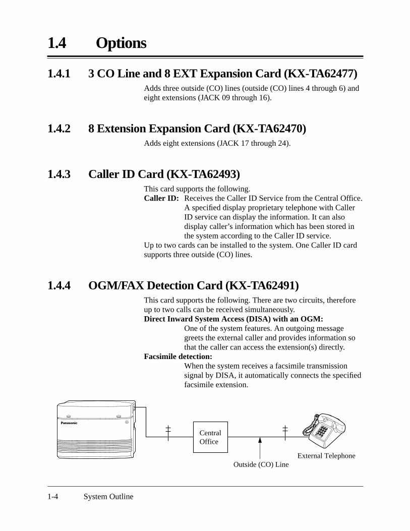
1.4.1 3 CO Line and 8 EXT Expansion Card (KX-TA62477)Adds three outside (CO) lines (outside (CO) lines 4 through 6) andeight extensions (JACK 09 through 16).
1.4.2 8 Extension Expansion Card (KX-TA62470)Adds eight extensions (JACK 17 through 24).
1.4.3 Caller ID Card (KX-TA62493)This card supports the following.Caller ID: Receives the Caller ID Service from the Central Office.
A specified display proprietary telephone with CallerID service can display the information. It can alsodisplay caller’s information which has been stored inthe system according to the Caller ID service.
Up to two cards can be installed to the system. One Caller ID cardsupports three outside (CO) lines.
1.4.4 OGM/FAX Detection Card (KX-TA62491)This card supports the following. There are two circuits, thereforeup to two calls can be received simultaneously.Direct Inward System Access (DISA) with an OGM:
One of the system features. An outgoing messagegreets the external caller and provides information sothat the caller can access the extension(s) directly.
Facsimile detection:When the system receives a facsimile transmissionsignal by DISA, it automatically connects the specifiedfacsimile extension.
Outside (CO) LineExternal Telephone
CentralOffice

1.4.5 Doorphone/Door Opener Card (KX-TA62460)
System Outline 1-5
Doorphone 1
Panasonic
DoorOpener 1
DoorOpener 2
DoorOpener 3
DoorOpener 4
Panasonic
Doorphone 2 Doorphone 3
Panasonic Panasonic
Doorphone 4
Paired Telephone (Proprietary Telephone)
DSS ConsoleKX-T7040
Pair
Panasonic
1.4.6 DSS Console (KX-T7040)Allows easy and quick access to stations and features. The BusyLamp Field shows the idle or busy status of each station. DSSConsoles are designed for use with a proprietary telephone. Thesystem supports up to two DSS Consoles per system.
This card supports four doorphones and four door openers. Thedoorphone is optional (KX-T30865).
1.5 Specifications
1-6 System Outline
Extension Connection Cable
KX-T7020KX-T7030KX-T7050KX-T7055KX-T7130
2 pair wire (T, R, H, L)
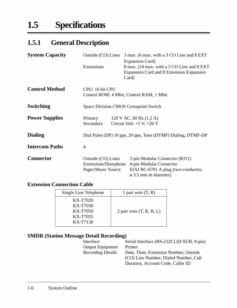
1.5.1 General Description
System Capacity Outside (CO) Lines 3 max. (6 max. with a 3 CO Line and 8 EXTExpansion Card)
Extensions 8 max. (24 max. with a 3 CO Line and 8 EXTExpansion Card and 8 Extension ExpansionCard)
Control Method CPU: 16 bit CPUControl ROM: 4 Mbit, Control RAM; 1 Mbit
Switching Space Division CMOS Crosspoint Switch
Power Supplies Primary 120 V AC, 60 Hz (1.2 A)Secondary Circuit Volt: +5 V, +26 V
Dialing Dial Pulse (DP) 10 pps, 20 pps, Tone (DTMF) Dialing, DTMF-DP
Intercom Paths 4
Connector Outside (CO) Lines 2-pin Modular Connector (RJ11)Extensions/Doorphone 4-pin Modular ConnectorPager/Music Source EIAJ RC-6701 A plug (two-conductor,
ø 3.5 mm in diameter)
Single Line Telephone 1 pair wire (T, R)
SMDR (Station Message Detail Recording) Interface Serial Interface (RS-232C) (D-SUB, 9-pin)Output Equipment PrinterRecording Details Date, Time, Extension Number, Outside
(CO) Line Number, Dialed Number, CallDuration, Account Code, Caller ID

1.5.2 Characteristics
System Outline 1-7
Station Loop Limit KX-T7020 / KX-T7030 / KX-T7050 / KX-T7055 / KX-T7130 RRRRRRRRRRRRRR 40 ΩSingle Line Telephone RRRRRRRRR 600 Ω including setDoorphone RRRRRRRRRRRRRRRRRRR 20 Ω
Minimum Leakage Resistance 15 000 ohms
Maximum Number of Station Instruments per Line1 for a KX-T7130, KX-T7020, KX-T7030, KX-T7050, KX-T7055or single line telephone2 by Parallel Connection of a proprietary telephone and a singleline telephone
Ring Voltage 80 Vrms at 20 Hz depending on the Ringing Load
Central Office Loop Limit 1 600 ohms max.
Environmental Requirements 0 °C – 40 °C 32 °F – 104 °F, 10 % – 90 % relative humidity
Hookswitch Flash Time Range 204 ms – 1 000 ms

1.5.3 System Capacity
1-8 System Outline
Lines, Cards, Station Equipment
Item Max. QuantityService Units 1
Outside (CO) Lines 6
Extension Jacks 24
Station Terminals 48
3 CO Line and 8 EXT Expansion Card 1
8 Extension Expansion Card 1
Caller ID Card 2
OGM/FAX Detection Card 1
Doorphone/Door Opener Card 1
Doorphones 4
Door Openers 4
External Pager 1
External Music Source 1
DSS Consoles 2
System Data
Item Max. QuantityOperator 1
System Speed Dialing 100
One-Touch Dialing 24 per extension(proprietary telephone)
Personal Speed Dialing 10 per extension
Call Park Areas 10
Absent Messages 6
Toll Restriction Classes 5
Extension Groups 8
Message Waiting 8 per extension(proprietary telephone)

Section 2Installation
This section contains the basic system installation and wiring instructions, as well as how to install the optional cards and units.

2.1 Before Installation
2-2 Installation
Please read the following notes concerning installation andconnection before installing the system and terminal equipment.
Safety Installation InstructionsWhen installing telephone wiring, basic safety precautions shouldalways be followed to reduce the risk of fire, electric shock andinjury to persons, including the following:1. Never install telephone wiring during a lightning storm.2. Never install telephone jacks in wet locations unless the jack is
specifically designed for wet locations.3. Never touch uninsulated telephone wires or terminals unless the
telephone line has been disconnected at the network interface.4. Use caution when installing or modifying telephone lines.
Installation PrecautionsThis system is designed for wall mounting only. Avoid installing inthe following places. (Doing so may result in malfunction, noise, ordiscoloration.)1. In direct sunlight and hot, cold, or humid places. (Temperature
range: 0 °C – 40 °C 32 °F – 104 °F)2. Sulfuric gases produced in areas where there are thermal
springs, etc. may damage the equipment or contacts.3. Places in which shocks or vibrations are frequent or strong.4. Dusty places, or places where water or oil may come into
contact with the system.5. Near high-frequency generating devices such as sewing
machines or electric welders.6. On or near computers, telexes, or other office equipment, as
well as microwave ovens or air conditioners. (It is preferable notto install the system in the same room with the aboveequipment.)
7. Install at least 1.8 m 6 feet away from radios and televisions.(Both the system and Panasonic proprietary telephones)
8. Do not obstruct area around the system (for reasons ofmaintenance and inspection — be especially careful to allowspace for cooling above and at the sides of the system).
Wiring PrecautionsBe sure to follow these instructions when wiring the unit:1. Do not wire the telephone cable in parallel with an AC power
source, computer, telex, etc. If the cables are run near thosewires, shield the cables with metal tubing or use shielded cablesand ground the shields.

2.1 Before Installation
Installation 2-3
2. If cables are run on the floor, use protectors to prevent the wiresfrom being stepped on. Avoid wiring under carpets.
3. Avoid using the same power supply outlet for computers,telexes, and other office equipment. Otherwise, the systemoperation may be interrupted by the induction noise from suchequipment.
4. Please use one pair telephone wire for extension connection of(telephone) equipment such as single line telephones, dataterminals, answering machines, computers, voice processingsystems, etc., except Panasonic proprietary telephones (e.g.KX-T7030, KX-T7130).
5. Unplug the system during wiring. After all of the wiring iscompleted, plug in the system.
6. Mis-wiring may cause the system to operate improperly. Referto Section 6.1 “Installation” and Section 6.2 “Connection”.
7. If an extension does not operate properly, disconnect thetelephone from the extension line and then connect again, orturn off the Power Switch of the system and then on again.
8. The system is equipped with a 3-wire grounding type plug. Thisis a safety feature. If you are unable to insert the plug into theoutlet, contact your electrician to replace your obsolete outlet.Do not defeat the purpose of the grounding-type plug.
9. Outside (CO) Lines should be installed with lightningprotectors. For details, refer to Section 2.3.3 “Outside (CO)Line Connection – Installing Lightning Protectors”.
POWER
Side View
Warning: Static sensitive connectors
Warning:Static sensitive devicesare used. To protectprinted circuit boardsfrom static electricity,do not touch connectorsindicated to the left. Todischarge body static,touch ground or wear agrounding strap.

2.2 Installation of the Main Unit
2-4 Installation
2.2.2 Location of Interfaces
Main Unit one
AC Cord one
Screws (Wall Mounting) three
Washers (Wall Mounting) three
Pager Connector one
Music Source Connector one
POWER
Side View
Serial InterfaceConnector (RS-232C)
AC Inlet
Protective Earth Terminal
Power Switch
Power Indicator
Extension Modular JacksOutside (CO) Line Modular Jacks
External Music JackPaging Jack
Strap (for cables)
2.2.1 Unpacking
Unpack the box and check the items below.
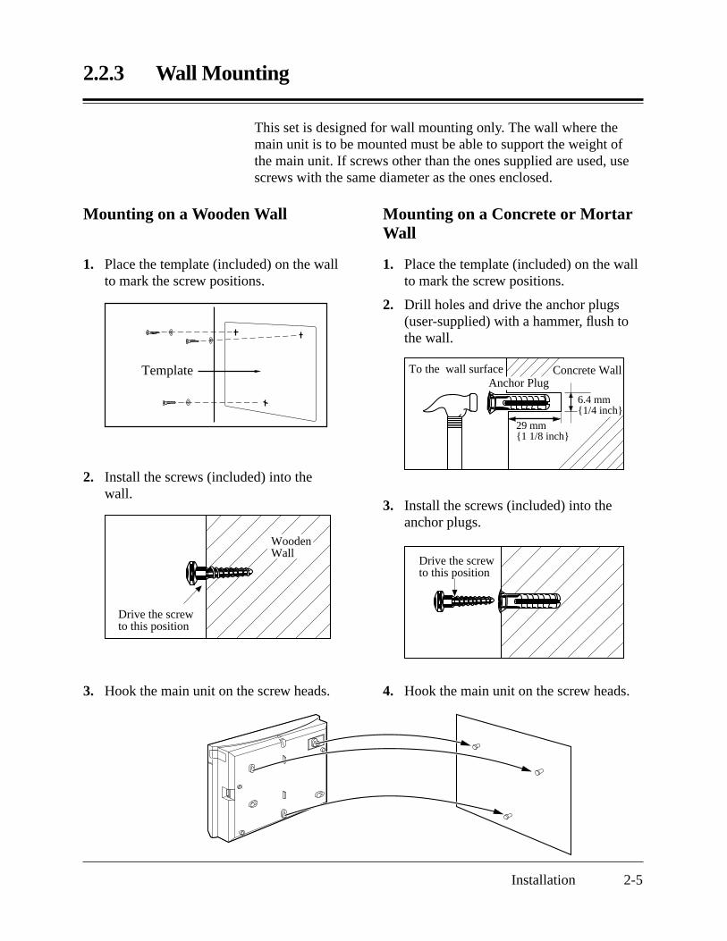
2.2.3 Wall Mounting
Installation 2-5
This set is designed for wall mounting only. The wall where themain unit is to be mounted must be able to support the weight ofthe main unit. If screws other than the ones supplied are used, usescrews with the same diameter as the ones enclosed.
Mounting on a Wooden Wall
Template
3. Hook the main unit on the screw heads.
1. Place the template (included) on the wallto mark the screw positions.
2. Install the screws (included) into thewall.
Mounting on a Concrete or MortarWall
Concrete WallTo the wall surfaceAnchor Plug
29 mm1 1/8 inch
6.4 mm1/4 inch
1. Place the template (included) on the wallto mark the screw positions.
2. Drill holes and drive the anchor plugs(user-supplied) with a hammer, flush tothe wall.
3. Install the screws (included) into theanchor plugs.
Drive the screwto this position
4. Hook the main unit on the screw heads.
Drive the screwto this position
WoodenWall

2.2.4 Frame Ground Connection
2-6 Installation
IMPORTANT!!!Connect the frame of the main unit to the ground.
1. Loosen the screw.
2. Insert the grounding wire.
3. Tighten the screw.
4. Connect the grounding wire to the ground.
In most of North America, the ground provided by the “Third wire ground” at the commercialpower outlet will be satisfactory. However, in some cases this ground may be installed incorrectly.Therefore, the following test procedure should be performed.
Test Procedure1. Obtain a suitable voltmeter and set it for a possible reading of up to 250 V AC.2. Connect the meter probes between the two main AC voltage points on the wall outlet. The
reading obtained should be 108 V AC – 132 V AC.3. Move one of the meter probes to the 3rd prong terminal (GND).
Either the same reading or a reading of 0 V should be obtained.4. If a reading of 0 V at one terminal and a reading of 108 V AC – 132 V AC at the other
terminal is not obtained, the outlet is not properly grounded.This condition should be corrected by a qualified electrician (per article 250 of the NationalElectrical Code).
5. If a reading of 0 V at one terminal and a reading of 108 V AC – 132 V AC at the otherterminal is obtained, then set the meter to the “OHMS/RX1” scale, place one probe at theGND Terminal and the other probe at the terminal which gave a reading of 0 V.A reading of less than 1 Ω should be obtained.If the reading is not obtained, the outlet is not adequately grounded. See a qualifiedelectrician.
ScrewTo the ground

2.3 Connection
Installation 2-7
6 Outside (CO) Lines
24 Extensions
DoorphonesKX-T30865
Door Openers
External Music Source
Amplifier Speaker
Printer or Computer
(two pair)
(two pair)
(two pair)
(two pair)
(two pair)
(two pair)
(one pair)
(one pair)
(one pair)
(one pair)
(one pair)
Single Line Telephone
Data Terminal
Cordless Phone
Telephone Answering Machine with Facsimile
Voice Processing System
KX-T7055
KX-T7050
KX-T7020
KX-T7030
KX-T7130
KX-T7040
Panasonic
Panasonic
Panasonic
Panasonic
to outside (CO) lines 1 – 3 (initial)to outside (CO) lines 4 – 6 (additional)(Lightning Protectors)
Extension jacks 01 – 08 (initial)Extension jacks 09 – 24 (additional)
: needs an Optional Card.
2.3.1 System Connection Diagram
Note• It is recommended that the extension of jack 01 is a
display proprietary telephone.• Parallel connection of telephones is possible. Refer
to Section 2.3.7, “Paralleled Telephone Connection”.

2.3.2 Opening the Front Cover
2-8 Installation
1. Loosen the screw.
2. Remove the top front cover.
Note The screw cannot be removed from the cover.
Top front coverScrew

2.3.3 Outside (CO) Line Connection
Installation 2-9
Connection1. Insert the modular plugs of the telephone line cords
(2-conductor wiring) into the modular jacks on the system.
2. Connect the line cord to the terminal board or the modular jacksfrom the Central Office jack.
POWER
To Terminal Board or Modular Jacks from the Central Office
T R
T: TipR: Ring
View of TEL Jack (Outside (CO) Line)
2.3.3 Outside (CO) Line Connection
2-10 Installation
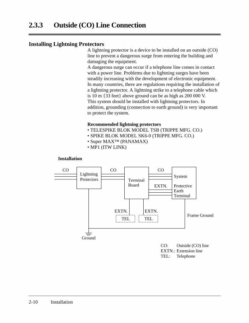
Installing Lightning ProtectorsA lightning protector is a device to be installed on an outside (CO)line to prevent a dangerous surge from entering the building anddamaging the equipment.A dangerous surge can occur if a telephone line comes in contactwith a power line. Problems due to lightning surges have beensteadily increasing with the development of electronic equipment.In many countries, there are regulations requiring the installation ofa lightning protector. A lightning strike to a telephone cable whichis 10 m 33 feet above ground can be as high as 200 000 V.This system should be installed with lightning protectors. Inaddition, grounding (connection to earth ground) is very importantto protect the system.
Recommended lightning protectors• TELESPIKE BLOK MODEL TSB (TRIPPE MFG. CO.)• SPIKE BLOK MODEL SK6-0 (TRIPPE MFG. CO.)• Super MAX™ (PANAMAX)• MP1 (ITW LINK)
Installation
TEL
CO CO
System
CO
EXTN.
EXTN.
Ground
EXTN.
TELFrame Ground
Protective Earth Terminal
Terminal Board
Lightning Protectors
CO: Outside (CO) lineEXTN.: Extension lineTEL: Telephone

2.3.3 Outside (CO) Line Connection
Installation 2-11
Installation of an Earth Rod
1) Installation location of the earth rod RR Near the protector2) Check obstructions RRRRRRRRR None3) Composition of the earth rod RRRRR Metal4) Depth of the earth rod RRRRRRR More than 50 cm
20 inches5) Size of the grounding wire RRRRRR Thickness more than
16 AWG
Note • The above example is only a recommendation.• The length of the earth rod and required depth depend on the
composition of the soil.
Lightning Protectors
CO
Grounding Wire
(Underground)
Rod
System

POWER
To extensions (JACK 01–08)
TH R L
H: HighT: TipR: RingL: Low
View of TEL Jack (Extension)
2.3.4 Extension Connection
2-12 Installation
Extension jacks 01 – 08 are for all kinds of telephones.
Telephone WiringThe maximum length of the extension line cord (twisted cable)which connects the system and the extension is as follows.
Diameter of the line Max. length
Single Line Telephone 22 AWG 1798 m 5900 feet(Station Loop Limit: 24 AWG 1128 m 3700 feet600 Ω including set) 26 AWG 698 m 2290 feetProprietary Telephone 22 AWG 360 m 1180 feet(Station Loop Limit: 24 AWG 229 m 750 feet40 Ω) 26 AWG 140 m 460 feet
2 or 4-conductor wiring is required for each extension as listedbelow. There are four pins possible for connection: “T” (Tip),“R” (Ring), “L” (Low) and “H” (High).
Note • If a KX-TA62493 is installed;Note the jack numbers for the facsimile and single line telephone whichhave Caller ID service.
• If a telephone or answering machine with an A-A1 relay is connected tothe system, set the A-A1 relay switch on the telephone or answeringmachine to the OFF position.
ConnectionInsert the modular plugs of the telephone line cords (2 or 4-conductor wiring) into the modular jacks on the system.
1 pair wire (T, R)
2 pair wire (L, H, T, R)
WiringTelephone
Single line telephone
Proprietary telephone (e.g., KX-T7030, KX-T7130)
2.3.5 External Pager (Paging Equipment) Connection
Installation 2-13
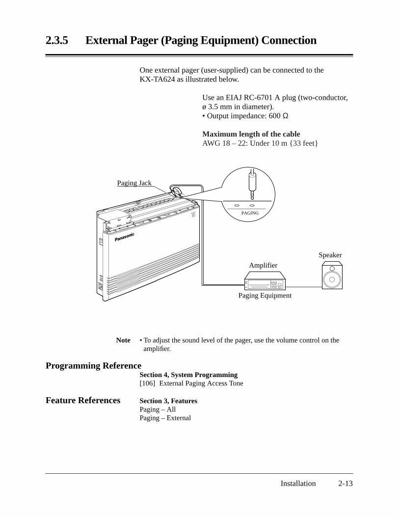
Note • To adjust the sound level of the pager, use the volume control on theamplifier.
Programming ReferenceSection 4, System Programming[106] External Paging Access Tone
Feature References Section 3, FeaturesPaging – AllPaging – External
One external pager (user-supplied) can be connected to theKX-TA624 as illustrated below.
Use an EIAJ RC-6701 A plug (two-conductor,ø 3.5 mm in diameter).• Output impedance: 600 Ω
Maximum length of the cableAWG 18 – 22: Under 10 m 33 feet
Speaker
Amplifier
Paging Equipment
POWER
Paging Jack
PAGING

2.3.6 External Music Source Connection
2-14 Installation
One music source, such as a radio (user-supplied), can be connectedto the KX-TA624 as illustrated below.
Insert the plug to the earphone/headphone jackon the external music source.Use an EIAJ RC-6701 A plug (two-conductor,ø 3.5 mm in diameter).• Input impedance: 8 Ω
Maximum length of the cableAWG 18 – 22: Under 10 m 33 feet
POWER EXT.MUSIC
External Music source
External Music Jack
Note • System programming for the music source used for Music on Hold isrequired.
• To adjust the sound level of the Music on Hold, use the volume controlon the external music source.
Programming ReferenceSection 4, System Programming[111] Hold Music Selection
Feature References Section 3, FeaturesBackground Music (BGM)Music on Hold

2.3.7 Paralleled Telephone Connection(for a Proprietary Telephone and a Single Line Telephone)
Installation 2-15
Any single line telephone can be connected in parallel with aproprietary telephone as follows.
Using a Modular T-Adaptor
Modular T-Adaptor(Panasonic KX-J66 or USOC RJA2X)
2-conductor wiring cordConnect pins “T” and “R”.
Proprietary Telephone Single Line Telephone
4-conductor wiring cordFor a proprietary telephone: Connect pins “T”, “R”, “H” and “L”.
Programming ReferenceSection 4, System Programming[610] Paralleled Telephone Connection
Feature Reference Section 3, FeaturesParalleled Telephone

2.3.8 Polarity Sensitive Telephone Connection
2-16 Installation
If the telephone is polarity sensitive, follow the procedure below:
1 2 3
4 5 6
7 8 9
0
Outside (CO) Line
Reverse here
Extension
1 2 3
4 5 6
7 8 9
0
Outside (CO) Line
Reverse here
Extension
1. Complete all the required extensionwiring.
2. Confirm that dialing can be done from allthe extensions using a touch-tonetelephone.If dialing fails, the polarity between theextension and the system must be reversed.
3. Reverse as shown.
4. Unplug the system.
5. Connect all outside (CO) lines.
6. Confirm that dialing can be done on thefollowing extension using a touch-tonetelephone.
Extension (T, R) of jack 01: Outside(CO) line 1
If dialing fails, the polarity between thesystem and the outside (CO) line must bereversed.
7. Reverse as shown.
8. Every time an extension telephone isreplaced, repeat the procedure above.
2.3.9 Printer and PC Connection
Installation 2-17
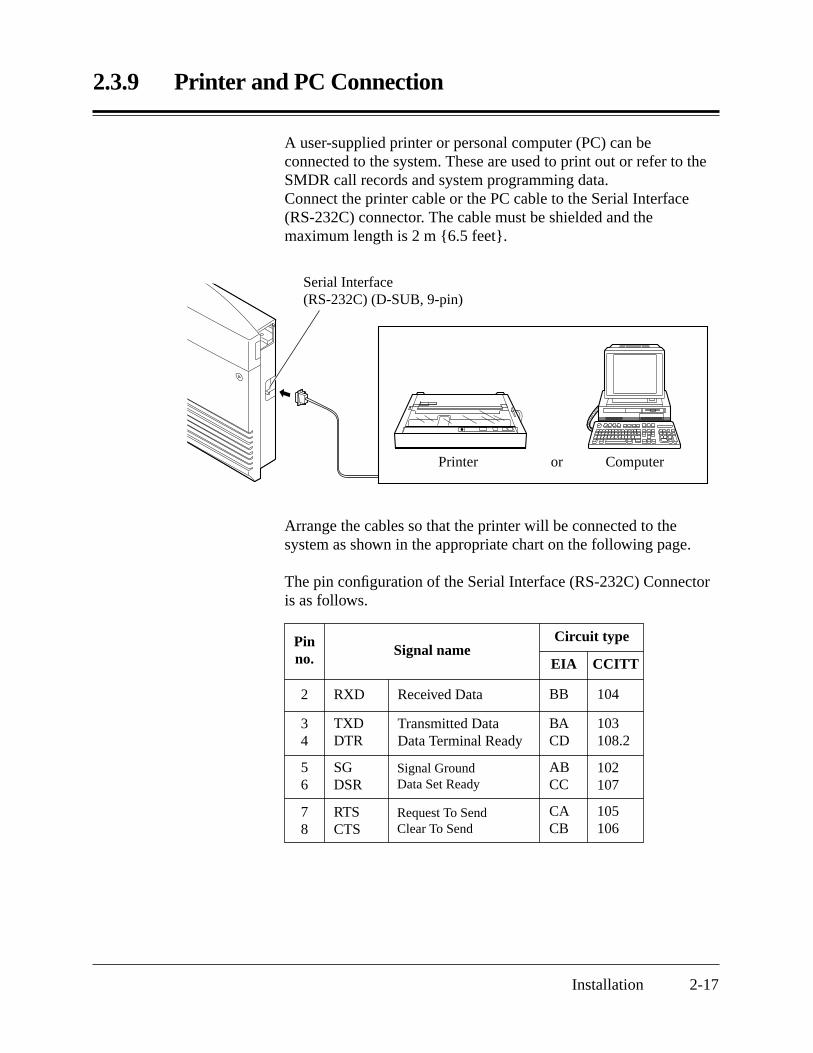
A user-supplied printer or personal computer (PC) can beconnected to the system. These are used to print out or refer to theSMDR call records and system programming data.Connect the printer cable or the PC cable to the Serial Interface(RS-232C) connector. The cable must be shielded and themaximum length is 2 m 6.5 feet.
Arrange the cables so that the printer will be connected to thesystem as shown in the appropriate chart on the following page.
The pin configuration of the Serial Interface (RS-232C) Connectoris as follows.
Serial Interface (RS-232C) (D-SUB, 9-pin)
Printer or Computer
Pinno.
2 RXD Received Data BB 104
34
TXDDTR
Transmitted DataData Terminal Ready
BACD
103108.2
56
SGDSR
Signal GroundData Set Ready
ABCC
102107
78
RTSCTS
Request To SendClear To Send
CACB
105106
Signal nameCircuit type
EIA CCITT
2.3.9 Printer and PC Connection
2-18 Installation
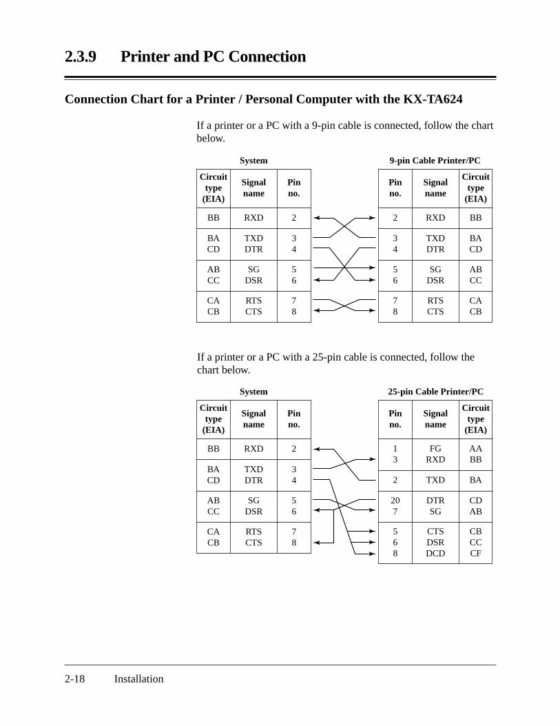
Connection Chart for a Printer / Personal Computer with the KX-TA624
If a printer or a PC with a 9-pin cable is connected, follow the chartbelow.
If a printer or a PC with a 25-pin cable is connected, follow thechart below.
Circuittype
(EIA)
BB RXD
System
2
BACD
TXDDTR
34
ABCC
SGDSR
56
CACB
RTSCTS
78
Signalname
Pin no.
Circuittype
(EIA)
BBRXD
9-pin Cable Printer/PC
2
BACD
TXDDTR
34
ABCC
SGDSR
56
CACB
RTSCTS
78
Signalname
Pin no.
Circuittype
(EIA)
BB RXD
System
2
BACD
TXDDTR
34
ABCC
SGDSR
56
CACB
RTSCTS
78
Signalname
Pin no.
Circuittype
(EIA)
AABB
BA
FGRXD
TXD
25-pin Cable Printer/PC
13
2
CDAB
DTRSG
207
CBCCCF
CTSDSRDCD
568
Signalname
Pin no.

2.3.9 Printer and PC Connection
Installation 2-19
Serial Interface (RS-232C) SignalsFrame Ground: FGConnects the unit frame and the earth ground conductor of the ACpower cord.
Transmitted Data: SD (TXD) RRRRRRRR (output)Conveys signals from the unit to the printer. A “Mark” condition isheld unless data or BREAK signals are being transmitted.
Received Data: RD (RXD) RRRRRRRRR (input)Conveys signals from the printer.
Request to Send: RS (RTS) RRRRRRRRR (output)This lead remains ON whenever DR (DSR) is ON.
Clear To Send: CS (CTS) RRRRRRRRR (input)When the CS (CTS) circuit is ON, it indicates that the printer isready to receive data from the unit. The unit does not attempt totransfer data or receive data when the CS (CTS) circuit is OFF.
Data Set Ready: DR (DSR) RRRRRRRRR (input)When the DR (DSR) circuit is ON, it indicates the printer is ready.The DR (DSR) circuit being ON does not indicate thatcommunication has been established with the printer.
Signal Ground: SGConnects the DC ground of the unit for all interface signals.
Data Terminal Ready: ER (DTR) RRRRRR (output)This signal line is turned ON by the unit to indicate that it is ON LINE. The ER (DTR) circuit being ON does not indicate thatcommunication has been established with the printer. It is switchedOFF when the unit is OFF LINE.
Data Carrier Detect: CD (DCD) RRRRRRR (input)When ON, it indicates the data terminal (DTE) that the carriersignal is being received.
Programming ReferencesSection 4, System Programming[800] SMDR RS-232C Communication Parameters[801] SMDR Parameter
Feature Reference Section 3, FeaturesStation Message Detail Recording (SMDR)

2.4 Installation of Optional Cards
2-20 Installation
2.4.1 Location of Optional Cards
The location of the optional cards is shown below.
Precaution To protect the printed circuit boards (P-boards) from static electricity, donot touch parts on the P-boards in the main unit and on the optionalcards. If accessing the part is required, wear a grounding strap.
The front covers are open.
Caller ID Card (KX-TA62493)Connector
OGM/FAX Detection Card (KX-TA62491) Connector
3 CO Line and 8 EXT Expansion Card(KX-TA62477) or8 Extension Expansion Card (KX-TA62470)ConnectorDoorphone/Door Opener Card
(KX-TA62460) Connector
Note:Power off the System, and unplug the AC cord before installing an optional card.

2.4.2 Caller ID and OGM/FAX Detection Card Installation
Installation 2-21
A Caller ID Card (KX-TA62493) and OGM/FAX Detection Card(KX-TA62491) can be installed to the system.
The Caller ID Card supports the following.Caller ID: Receives the Caller ID Service from the Central Office.
A display proprietary telephone with Caller ID service candisplay the information. It can also display caller’s informationwhich has been stored in the system according to the Caller IDservice.
The OGM/FAX Detection Card supports the following.Direct Inward System Access (DISA) with an OGM:
One of the system features. An outgoing message greets theexternal caller and gives information so that the caller canaccess the extension(s) directly.
Facsimile detection:When the system receives a facsimile transmission signal byDISA, it automatically connects the specified facsimileextension.
1. Remove the two screws.
Screws
2. Open the bottom front cover.
Bottom front cover

2.4.2 Caller ID and OGM/FAX Detection Card Installation
2-22 Installation
Caller ID Card(KX-TA62493)
Install the Caller ID Card forthe KX-TA62477 here.
NotePlease do not damage this part.
OGM/FAX Detection Card(KX-TA62491)
3. Attach the optional cards.
4. Insert the flat cables to each card connector.
5. Close the cover.
Condition • Be sure the frame of the main unit is connected to the ground. Refer toSection 2.2.4 “Frame Ground Connection”.
Programming ReferenceSee “Programming References” in Section 3, Features, Caller ID andDirect Inward System Access (DISA).
Feature References Section 3, FeaturesCaller IDDirect Inward System Access (DISA)Outgoing Message (OGM)
Flat cables

2.4.3 Doorphone and Door Opener Connection
Installation 2-23
Four doorphones (KX-T30865) and four door openers (user-supplied) can be installed.
Maximum cable lengthThe maximum length of the doorphone and door opener line cordwhich connects the system is as follows.
Diameter of the line Max. lengthDoorphone 22 AWG 180 m 590 feet(Station Loop 24 AWG 113 m 370 feetLimit: 20 Ω) 26 AWG 70 m 230 feetDoor Opener 22 AWG 180 m 590 feet
Installing the Doorphone
1. Loosen the screw to open the doorphone unit.
3. Connect the wires to the screws located in the front cover.
4. Put the doorphone together and re-install the screw.
Type 1: When a doorphone plate has beenfixed to the wall.
Type 2: When you wish to install thedoorphone directly to the wall.
Screws
To the terminal box
Panasonic
Screw
2. Attach the base cover to a wall using two screws.
Note Two kinds of screws are included. Please choose theappropriate one depending on your type of wall.

2.4.3 Doorphone and Door Opener Connection
2-24 Installation
Doorphone/Door Opener Installation
Attach the Doorphone/Door Opener Card to the main unit, connectthe cord to the doorphone/door opener card connector and securethe screw.
Doorphone Connectors
Door Opener Terminal
Doorphone/Door Opener Card (KX-TA62460)
Screw
Doorphone/Door Opener Card Card Connector
2.4.3 Doorphone and Door Opener Connection
Installation 2-25
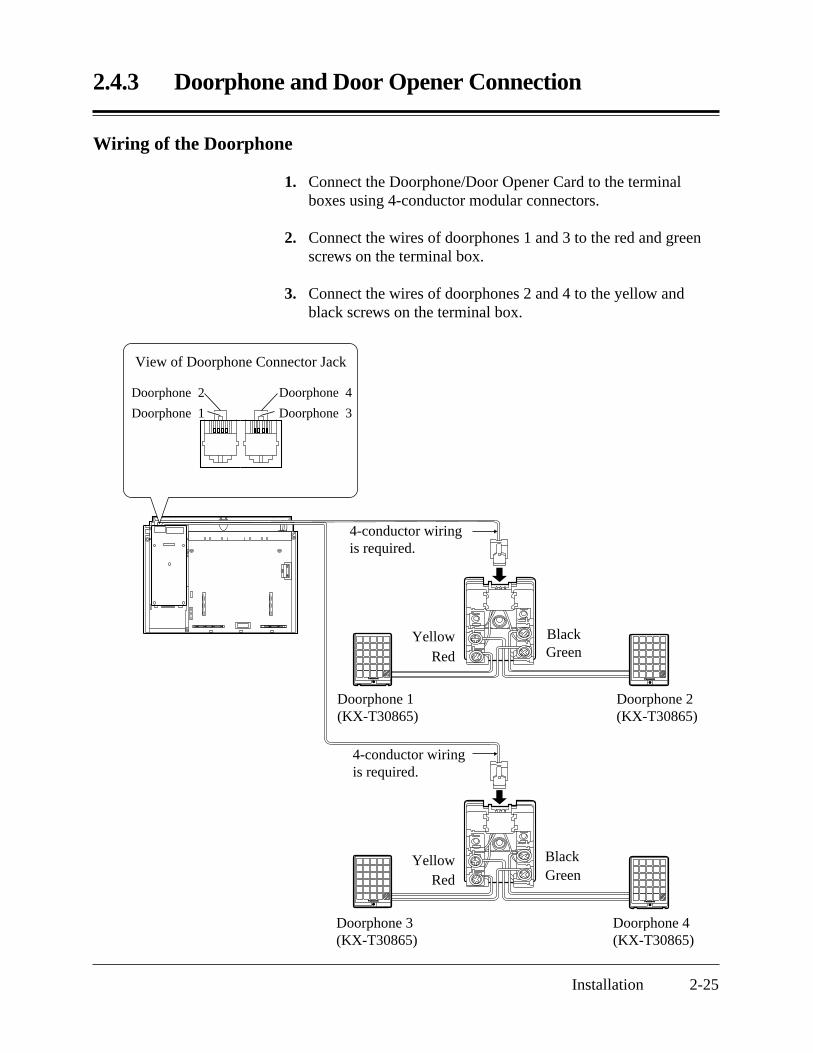
Wiring of the Doorphone
1. Connect the Doorphone/Door Opener Card to the terminalboxes using 4-conductor modular connectors.
2. Connect the wires of doorphones 1 and 3 to the red and greenscrews on the terminal box.
3. Connect the wires of doorphones 2 and 4 to the yellow andblack screws on the terminal box.
Panasonic Panasonic
Panasonic Panasonic
YellowRed
BlackGreen
4-conductor wiringis required.
4-conductor wiringis required.
Doorphone 1(KX-T30865)
Doorphone 2(KX-T30865)
YellowRed
BlackGreen
Doorphone 3(KX-T30865)
Doorphone 4(KX-T30865)
View of Doorphone Connector Jack
Doorphone 2
Doorphone 3Doorphone 1
Doorphone 4

2.4.3 Doorphone and Door Opener Connection
2-26 Installation
Connecting Door Openers
While pressing the button below a hole with a driver, insert the wirefrom the door opener into the hole.
Note • We recommend using UL1015 wire or the equivalent for wiring.• The wire should be between 0.4 mm and 1.2 mm 1/64 inch – 3/64 inch
in diameter including the coating.
Door opener 1Door opener 2
Door opener 3
Door opener 4
To the door openers
D = 0.4 mm – 1.2 mm 1/64 inch – 3/64 inch

2.4.3 Doorphone and Door Opener Connection
Installation 2-27
Programming ReferencesSection 4, System Programming[700]–[702] Doorphone Ringing Assignment — Day/Night/Lunch[703]–[705] Door Opener Assignment — Day/Night/Lunch
Feature References Section 3, FeaturesDoor OpenerDoorphone Call
2.4.4 Installing a 3 CO Line and 8 EXT Expansion Card (KX-TA62477) and 8 Extension Expansion Card (KX-TA62470)
2-28 Installation
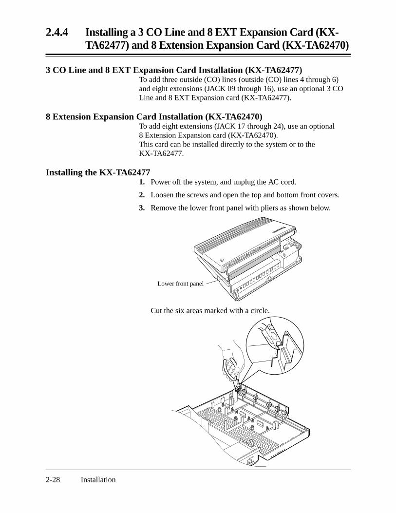
3 CO Line and 8 EXT Expansion Card Installation (KX-TA62477)To add three outside (CO) lines (outside (CO) lines 4 through 6)and eight extensions (JACK 09 through 16), use an optional 3 COLine and 8 EXT Expansion card (KX-TA62477).
8 Extension Expansion Card Installation (KX-TA62470)To add eight extensions (JACK 17 through 24), use an optional8 Extension Expansion card (KX-TA62470).This card can be installed directly to the system or to theKX-TA62477.
Installing the KX-TA624771. Power off the system, and unplug the AC cord.
2. Loosen the screws and open the top and bottom front covers.
3. Remove the lower front panel with pliers as shown below.
Lower front panel
Cut the six areas marked with a circle.
2.4.4 Installing a 3 CO Line and 8 EXT Expansion Card (KX-TA62477) and 8 Extension Expansion Card (KX-TA62470)
Installation 2-29
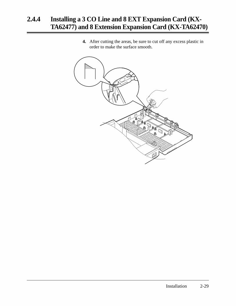
4. After cutting the areas, be sure to cut off any excess plastic inorder to make the surface smooth.

2-30 Installation
2.4.4 Installing a 3 CO Line and 8 EXT Expansion Card (KX-TA62477) and 8 Extension Expansion Card (KX-TA62470)
5. First, insert the plastic spacer into the hole near the Caller IDcard connector on the KX-TA62477. Attach the extensionconnectors to the system, install the KX-TA62477 and securethe two extension bolts.
Extension Bolts
Extension Connectors
3 CO Line and 8 EXT Expansion Card(KX-TA62477)
Caller ID Card Connector
Spacer
6. Insert the modular plugs of the telephone line cords(2-conductor wiring) into the modular jacks (CO 4 through 6)on the card. Refer to 2.3.3, Outside (CO) Line Connection.
7. Connect the line cords to the terminal board or the modularjacks from the Central Office.
8. Insert the modular plugs of the telephone line cords (2 or 4-conductor wiring) into the modular jacks (JACK 09 through 16)on the card. Refer to 2.3.4, Extension Connection.
9. Attach the optional Caller ID card (KX-TA62493) to the CallerID Card connector, if desired.Refer to 2.4.2, Caller ID and OGM/FAX Detection CardInstallation.

Screws
Extension Connectors
8 Extension Expansion Card(KX-TA62470)
Installation 2-31
2.4.4 Installing a 3 CO Line and 8 EXT Expansion Card (KX-TA62477) and 8 Extension Expansion Card (KX-TA62470)
4. Attach the extension connectors to the system first, install theKX-TA62470 and secure the two screws.
Top front panel
Installing the KX-TA624701. Power off the system, and unplug the AC cord.
2. Loosen the screws and open the top and bottom front covers.
3. Remove the lower front panel. If you install the KX-TA62470to a KX-TA62477, remove the top front panel in the same wayas described in “ Installing the KX-TA62477”.
5. Insert the modular plugs of the telephone line cords (2 or 4-conductor wiring) into the modular jacks (JACK 17 through 24)on the card. Refer to 2.3.4, Extension Connection.

2-32 Installation
2.4.4 Installing a 3 CO Line and 8 EXT Expansion Card (KX-TA62477) and 8 Extension Expansion Card (KX-TA62470)
When you install the KX-TA62470 to the KX-TA62477, installthe KX-TA62477 first and then the KX-TA62470.
3 CO Line and 8 EXT Expansion Card(KX-TA62477)
8 Extension Expansion Card(KX-TA62470)
Screws
Extension Connectors
Extension Bolts
Extension Connectors
Spacer

2.4.5 Securing the cords
Installation 2-33
1. Wrap the strap around all of the cords.
2. Close the covers and secure the screws.
Note • To remove the strap, loosen the rivet with a driver.
Rivet
2.5 Auxiliary Connection for Power FailureTransfer
2-34 Installation
Power failure transfer connects a specific single line telephone toselected outside (CO) lines in the event of system power failure, asfollows.
Outside (CO) Line 1 – Extension (T, R) Jack 01Outside (CO) Line 4 – Extension (T, R) Jack 09Connection of outside (CO) lines 1 and 4, and the respectiveextensions require no auxiliary connection.
Note • In the event of a power failure, system memory is protected by a factory-provided lithium battery. There is no memory loss except the Camp-on,Saved Number Redial, Last Number Redial, Call Park and MessageWaiting memories.
• The system automatically changes the current connection to the aboveconnection when the power supply stops.
• Proprietary telephones cannot be used during a system power failure.Therefore, we recommend connecting single line telephones in parallelwith the proprietary telephones connected to JACK 01 and 09.
Feature References Section 3, FeaturesParalleled TelephonePower Failure Transfer
2.6 Closing the Front Cover
Installation 2-35
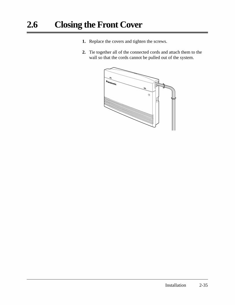
1. Replace the covers and tighten the screws.
2. Tie together all of the connected cords and attach them to thewall so that the cords cannot be pulled out of the system.
2.7 Starting the System for the First Time
2-36 Installation
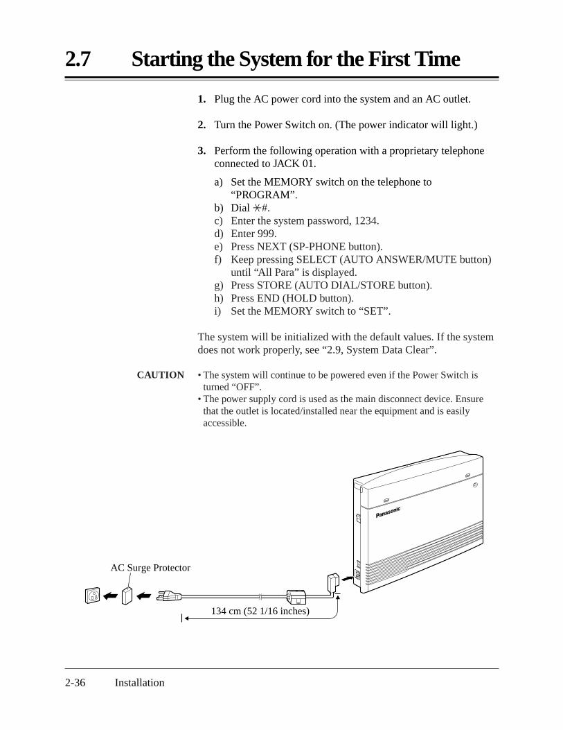
1. Plug the AC power cord into the system and an AC outlet.
2. Turn the Power Switch on. (The power indicator will light.)
3. Perform the following operation with a proprietary telephoneconnected to JACK 01.
a) Set the MEMORY switch on the telephone to“PROGRAM”.
b) Dial *#.c) Enter the system password, 1234.d) Enter 999.e) Press NEXT (SP-PHONE button).f) Keep pressing SELECT (AUTO ANSWER/MUTE button)
until “All Para” is displayed.g) Press STORE (AUTO DIAL/STORE button).h) Press END (HOLD button).i) Set the MEMORY switch to “SET”.
The system will be initialized with the default values. If the systemdoes not work properly, see “2.9, System Data Clear”.
CAUTION • The system will continue to be powered even if the Power Switch isturned “OFF”.
• The power supply cord is used as the main disconnect device. Ensurethat the outlet is located/installed near the equipment and is easilyaccessible.
AC Surge Protector
134 cm (52 1/16 inches)

2.8 System Restart
Installation 2-37
After starting the system, if the system does not operate properly,restart the system.Before restarting the system, try the system feature again to confirmwhether there definitely is a problem or not.System Restart causes the following.
1. Camp-on is cleared.2. Calls on Hold are terminated.3. Calls on Exclusive Hold are terminated.4. Calls in progress are terminated.5. Call Park is cleared.6. Last Number Redial is cleared.7. Saved Number Redial is cleared.8. Message Waiting is cleared.
Other data is not cleared by System Restart.
1. Turn the Power switch off and then on.
Notice If the system still does not operate properly, please see Section 2.9,“System Data Clear”.

2.9 System Data Clear
2-38 Installation
When the system does not operate properly after restarting, you canclear the programming data stored in the system. The system willrestart with the default settings. First, try system program [999]. Ifthe system still does not operate properly, please follow theprocedure below.
1. Loosen the screws and open the top and bottom front covers.
2. Slide the System Clear Switch to the “CLEAR” position.
3. Press the Reset Button.
4. Return the System Clear Switch to the “NORMAL” positionbefore the power indicator stops flashing.(The power indicator will flash for about 10 seconds.)
CAUTION Before touching the System Clear Switch and Reset Button, put on agrounding strap.
Notice After pressing the Reset Button, return the System Clear Switch to the“NORMAL” position in step 4 before the power indicator stops flashing.Otherwise, the system will not clear.
Programming ReferenceSection 4, System Programming[999] System Data Clear
CLE
AR
/NO
RM
AL
System Clear Switch
Reset Button

Section 3Features
This section describes every basic, optional, and programmable feature in alphabetical order. It also provides
information about the conditions, connection references, programming required, related features, and operation
for every feature.

3-2 Features
A 3 Features
Absent Message Capability
Description Allows an extension user to set a message which will be displayedat the calling extension to show the reason for the called extension’sabsence. Six messages can be programmed as desired, which areavailable for every extension user. Setting or canceling a messagecan be done by individual extension users but only callers with adisplay telephone can view the message.
Conditions • The six messages are shown below. “%” means a parameter to beentered when assigning a message at an extension.(1) Will Return Soon(2) Gone Home(3) At Ext %%% (extension number)(4) Back at %% : %% AM (or PM) (hour : minute)(5) Out Until %% / %% (month / day)(6) In a Meeting
• An extension user can only select one message at a time. The selectedmessage is displayed every time the user goes off-hook.
Programming ReferencesNo programming required.
Feature References None
Operation Reference Telephone Features— User Manual Absent Message Capability

Features 3-3
3 Features AAccount Code Entry
Description An Account Code is used to identify incoming and outgoing outsidecalls for accounting and billing purposes. The account code isappended to the Station Message Detail Recording (SMDR) callrecord. For incoming outside calls, account codes are optional. Foroutgoing outside calls, there are four modes available to enter anaccount code: Verify-All mode, Verify-Toll mode, Forced mode, andOption mode. One mode is selected for each extension.In Verify-All mode, the user must always enter a pre-assignedaccount code when making any of the following calls unless it haspreviously been stored in memory.• Call Forwarding – to Outside (CO) Line• Last Number Redial• Line Access • One-Touch Dialing• Personal Speed Dialing• Pickup Dialing• Saved Number Redial• System Speed DialingIn Verify-Toll mode, the user can enter a pre-assigned account codeonly when the user needs to override toll restriction. Calls with COSnumbers 3 through 5 will be treated as calls with COS number 2.Calls with COS numbers 1 and 2 will not be affected.In Forced mode, the user must always enter an account code. Thecode can be any number.In Option mode, the user can enter any account code if needed.
Conditions • An account code can be stored into Memory Dialing (System/PersonalSpeed Dialing, One-Touch Dialing, Pickup Dialing, Call Forwarding – toOutside (CO) Line).
• Account code entry after CPC detection must be done within 30 seconds.Otherwise, the SMDR call record is activated and the code cannot beentered.
• In any mode, emergency dial numbers stored in program[309] “Emergency Dial Number Set” can be dialed out without anaccount code entry.
Programming ReferencesSection 4, System Programming[310] Account Codes[601]–[603] TRS – Class of Service (COS) Assignment
— Day/Night /Lunch[605] Account Code Entry Mode [805] SMDR Account Code Selection
Feature Reference Section 3, FeaturesToll Restriction Override by Account Codes
Operation Reference Telephone Features — User Manual Account Code Entry

3-4 Features
A 3 Features
Answering, Direct Outside (CO) Line
Description Allows a proprietary telephone user to answer an incoming call bysimply pressing the appropriate CO button without lifting thehandset or pressing the SP-PHONE/MONITOR button.
Condition • This feature allows the user to specify which line will be answered whenmultiple incoming lines are ringing.
Programming ReferencesNo programming required.
Feature Reference Section 3, FeaturesOutside (CO) Line Connection Assignment
Operation Reference Telephone Features— User Manual Answering, Direct Outside (CO) Line

Features 3-5
3 Features AAutomatic Callback Busy (Camp-On)
Description Allows the caller to be notified when the called party or selectedoutside (CO) line becomes free.Automatic Callback – ExtensionIf the caller answers the callback ringing (Camp-On Recall), thecalled extension will automatically start ringing.Automatic Callback – Outside (CO) Line If the caller answers the callback ringing (Camp-On Recall), theline will be automatically selected to allow the user to make anoutside call.
Conditions • If the callback ringing (Camp-On Recall) is not answered in four rings(within 10 seconds), the callback will be canceled.
• More than one extension user can set this function to one extension oroutside (CO) line at the same time.
Programming ReferencesNo programming required.
Feature References None
Operation Reference Telephone Features— User Manual Automatic Callback Busy (Camp-On)

3-6 Features
B 3 Features
Background Music (BGM)
Description Allows a proprietary telephone user to listen to background musicfrom the speaker monitor on their telephone.
Conditions • A user-supplied external music source, such as a radio, must beconnected. One external music source can be connected to the system.
• The music source is used for BGM and/or Music on Hold.• The music is interrupted when you go off-hook.
Connection ReferenceSection 2, Installation2.3.6 External Music Source Connection
Programming ReferencesNo programming required.
Feature Reference Section 3, FeaturesMusic on Hold
Operation Reference Telephone Features— User Manual Background Music (BGM)

Features 3-7
3 Features BBusy Lamp Field
Description The LED (Light Emitting Diode) indicators of the DSS (DirectStation Selection) buttons, corresponding to selected extensions,show whether the extensions are idle or busy.
Conditions • This function is available for flexible CO buttons assigned as DSSbuttons on proprietary telephones and DSS buttons on DSS Consoles.
• A DSS button indicator lights red if the corresponding extension is busy.
Programming ReferenceStation Programming RRRRRRRRRR User ManualFlexible Button Assignment – Direct Station Selection (DSS) Button
Feature Reference Section 3, FeaturesButton, Direct Station Selection (DSS)
Operation References Not applicable.
Busy Station Signaling (BSS)
Description When attempting to call a busy extension, Busy Station Signalingallows you to signal the extension to answer your call. The calledextension user hears a Call Waiting tone and then is able to answerthe call.
Condition • This feature only works if the called extension has activated CallWaiting. If Call Waiting is activated, the caller will hear a ringback tone.If not, the caller will hear a reorder tone.
Programming ReferencesNo programming required.
Feature Reference Section 3, Features Call Waiting
Operation Reference Telephone Features— User Manual Busy Station Signaling (BSS)
3-8 Features
B 3 Features
Button, Direct Station Selection (DSS)
Description A DSS button allows a proprietary telephone user one-touch accessto other extension users.
Conditions • A flexible CO button and MESSAGE button on a proprietary telephonecan be assigned as a DSS button using station programming.
• DSS buttons are provided on DSS Consoles with a default setting.Changing the setting is possible from a paired telephone using stationprogramming. Day, Night, Lunch and Station Lock buttons can beassigned to DSS buttons on DSS Consoles.
• Once a button is assigned as a DSS button, the Busy Lamp Field (BLF)status is available.
• The mode of a DSS button can be programmed to disconnect the outside(CO) line and call the extension, or hold and transfer the call to theextension (One-Touch Transfer Using a DSS Button).
Programming ReferencesSection 4, System Programming[005] One-Touch Transfer Using a DSS ButtonStation Programming RRRRRRRRRR User ManualFlexible Button Assignment – Direct Station Selection (DSS) ButtonDSS Console Features RRRRRRRRR User ManualStation Programming
Feature References Section 3, FeaturesBusy Lamp Field Remote Station Lock ControlDSS Console (KX-T7040) Time (Day/Night/Lunch) ServiceOne-Touch Transfer Using a DSS Button
Operation References Basic Operations— User Manual Making Calls
Telephone FeaturesCall Transfer – to ExtensionOperator/Manager Service FeaturesTime (Day/Night/Lunch) Service SettingRemote Station Lock ControlDSS Console Features

Features 3-9
3 Features BButton, Flexible
Description The use of Flexible Buttons is determined by station programming.The following four types of Flexible Buttons are provided onproprietary telephones (PT) and DSS Consoles:• Flexible CO buttons (provided on a PT only)• Flexible Direct Station Selection (DSS) buttons (provided on a
DSS Console only)• MESSAGE button (provided on a PT except for the KX-T7055)• Programmable Feature (PF) buttonsThe table below shows all of the features which can be assigned toFlexible Buttons.
“” indicates that the feature is available.
† Available when the KX-TA624 is connected to a Proprietary Telephone capablePanasonic Voice Processing System (one that supports APT Integration; KX-TVS50).
PF(PT/DSS)
MESSAGEDSS
(DSS)CO(PT)
Button
Features to be assigned
Single-CO
Group-CO
Caller ID Indication
Caller ID Selection
Conference
FWD/DND
Log-In/Log-Out
Other-CO
Saved Number Redial
Day
Lunch
Night
Station Lock
Message Waiting
Live Call Screening (LCS)†
LCS Cancel†
Voice Mail Transfer†
Direct Station Selection (DSS)
One-Touch Dialing

3-10 Features
B 3 Features
Condition • Incoming and outgoing calls on a line are shown in the followingpriority.
Single-CO > Group-CO
Programming ReferencesStation Programming RRRRRRRRRR User ManualFlexible Button AssignmentDSS Console Features (KX-T7040) RRRR User Manual
Feature References Section 3, Features Buttons on Proprietary TelephonesDSS Console (KX-T7040)
Operation References Not applicable.

Features 3-11
3 Features BButton, Group-CO (G-CO)
Description To support efficient utilization of outside (CO) lines, a group ofoutside (CO) lines (outside (CO) line group) can be assigned to aCO button. The function is referred to as Group-CO (G-CO). Anyincoming call from any outside (CO) line in the outside (CO) linegroup arrives at the G-CO button. To make an outside call, the usercan access an idle outside (CO) line in the group by simply pressingthe assigned G-CO button.
Conditions • A G-CO button is not originally provided on a proprietary telephone(PT). It can be programmed on a CO button by station programming.
• The extension for receiving and/or originating calls on outside (CO)lines must be programmed.
• The same outside (CO) line group can be assigned to more than one G-CO button on the same PT.
• The same line can be assigned to a Single-CO (S-CO) button and aG-CO button.
• Immediate, delayed, no ringing or no incoming call (disable) can beselected on an extension-outside (CO) line basis.
• Users can choose a desired ringing pattern for each outside (CO) line bysystem programming.
Programming ReferencesSection 4, System Programming[400] Outside (CO) Line Connection Assignment[404] Outside (CO) Line Group Assignment[405]–[407] Flexible Outward Dialing Assignment — Day/Night/Lunch[408]–[410] Flexible Ringing Assignment — Day/Night/Lunch[411]–[413] Delayed Ringing Assignment — Day/Night/Lunch[423] Outside (CO) Line Ringing Pattern SelectionStation Programming RRRRRRRRRR User ManualFlexible Button Assignment – Group-CO (G-CO) Button
Feature References Section 3, FeaturesAnswering, Direct Outside (CO) Line Ringing, DelayedLED Indication, Outside (CO) Line Ringing Pattern Selection for Line Access, Outside (CO) Line Group Intercom Calls and OutsideOutside (CO) Line Group (CO) Lines
Operation References Basic Operations— User Manual Making Calls
Receiving CallsTelephone FeaturesAnswering, Direct Outside (CO) LineOutward Dialing – Line Access, Automatic, Outside (CO) Line Group

3-12 Features
B 3 Features
Button, Other-CO (O-CO)
Description Outside (CO) lines, which are not assigned to a S-CO or G-CObutton, can be assigned to a flexible CO button on a proprietarytelephone (PT). The assigned button serves as the Other-CO(O-CO) button. An incoming call on an outside (CO) line arrives atthe O-CO. To make an outside call, the PT user simply presses theassigned O-CO button.
Conditions • An O-CO button is not originally provided on a PT. A flexible CObutton can be assigned as an O-CO button by station programming.
• Immediate, delayed, no ringing or no incoming call (disable) can beselected on an extension – outside (CO) line basis.
• Users can choose a desired ringing pattern for each outside (CO) line bysystem programming.
Programming ReferencesSection 4, System Programming[400] Outside (CO) Line Connection Assignment[404] Outside (CO) Line Group Assignment[405]–[407] Flexible Outward Dialing Assignment — Day/Night/Lunch[408]–[410] Flexible Ringing Assignment — Day/Night/Lunch[411]–[413] Delayed Ringing Assignment — Day/Night/Lunch[423] Outside (CO) Line Ringing Pattern SelectionStation Programming RRRRRRRRRR User ManualFlexible Button Assignment – Other-CO (O-CO) Button
Feature References Section 3, FeaturesAnswering, Direct Outside (CO) Line Line Access, DirectLED Indication, Outside (CO) Line Ringing, DelayedLine Access, Automatic Ringing Pattern Selection for
Intercom Calls and Outside(CO) Lines
Operation References Basic Operations— User Manual Making Calls
Receiving CallsTelephone FeaturesOutward Dialing – Line Access, Automatic

Features 3-13
3 Features BButton, Single-CO (S-CO)
Description A Single-CO (S-CO) button is an outside (CO) line access button.This allows a proprietary telephone user to access a specific line bypressing a S-CO button. An incoming call can be directed to aS-CO button.
Conditions • The default setting for CO buttons is changeable. (Flexible CO Button)• A S-CO button provides outside (CO) line status.• One outside (CO) line can be assigned to both a S-CO and a Group-CO
(G-CO) button.• Incoming calls are indicated on a proprietary telephone, when an
extension is assigned as the incoming call destination and a S-CO,G-CO and/or O-CO button is assigned.
• Immediate, delayed, no ringing or no incoming call (disable) can beselected on an extension–outside (CO) line basis.
• Users can choose a desired ringing pattern for each outside (CO) line bysystem programming.
Programming ReferencesSection 4, System Programming[400] Outside (CO) Line Connection Assignment[404] Outside (CO) Line Group Assignment[405]–[407] Flexible Outward Dialing Assignment — Day/Night/Lunch[408]–[410] Flexible Ringing Assignment — Day/Night/Lunch[411]–[413] Delayed Ringing Assignment — Day/Night/Lunch[423] Outside (CO) Line Ringing Pattern SelectionStation Programming RRRRRRRRRR User ManualFlexible Button Assignment – Single-CO (S-CO) Button
Feature References Section 3, FeaturesAnswering, Direct Outside (CO) Line Line Access, IndividualLED Indication, Outside (CO) Line Ringing, DelayedLine Access, Direct Ringing Pattern Selection for
Intercom Calls and Outside(CO) Lines
Operation References Basic Operations— User Manual Making Calls
Receiving CallsTelephone FeaturesOutward Dialing – Line Access, Individual

3-14 Features
B 3 Features
Buttons on Proprietary Telephones
Description Proprietary telephones are provided with the feature/line accessbuttons listed below.
KX-T Proprietary Telephones
: The button is provided on the designated telephone.: The button has a LED (Light Emitting Diode).* : Buttons which can be changed to function as a feature button are called
flexible buttons.!: The button does not have a LED.(x): Shows the number of buttons only if more than one button is provided.
AUTO ANSWER/MUTE
AUTO DIAL/STORE
CO*
CONF
FLASH
FWD/DND
HOLD
INTERCOM
MESSAGE*
MONITOR
PAUSE
PF (Programmable Feature)
REDIAL
SAVE
SP-PHONE
TRANSFER
(12)
(4)
(12)
(4)
(12)
!
(4)
!
(3)
!
!
(3)
(12)
(12)
71307055705070307020Buttons

Features 3-15
3 Features BThe functions of the listed buttons are described below.AUTO ANSWER/MUTE: Used for answering an extensionautomatically, or turns the microphone off during a conversation.AUTO DIAL/STORE: Used for System Speed Dialing and storingprogram changes.CO (Central Office line): Can make or receive an outside call orcan be re-assigned to a different CO or various feature buttons.CONF (Conference): Used to establish a three-party conference.FLASH: Allows you to disconnect the current call and originateanother call without hanging up (Flash). Sends a flash signal to theCentral Office or host PBX to access their features (ExternalFeature Access).FWD/DND (Call Forwarding/Do Not Disturb): Used to programCall Forwarding, and set Do Not Disturb.HOLD: Used to place a call on hold.INTERCOM: Used to make or receive intercom calls.MESSAGE: Used to send a message, display the current message,call back the message sender, or can be assigned as another featurebutton.MONITOR: Used for a hands-free operation.PAUSE: Inserts a pause in a speed dial number.PF (Programmable Feature): This flexible button can beprogrammed as a One-Touch Dialing button, if desired.REDIAL: Used for Last Number or Automatic Redialing.SAVE: Used to store a dialed telephone number for Saved NumberRedial.SP-PHONE (Speakerphone): Used for a hands-free speakerphoneoperation. Pressing the button causes the telephone to switchbetween the handset and hands-free operation.TRANSFER: Transfers a call to another extension or externaldestination.
Conditions • Certain buttons are equipped with light indicators (LED’s) to show theline or feature status.
• CO buttons can be classified according to the following three types:Single-CO (S-CO) button / Group-CO (G- CO) button /Other-CO (O- CO) button
Programming ReferenceStation Programming RRRRRRRRRR User ManualFlexible Button Assignment
Feature References None
Operation References Refer to the appropriate operating instructions.— User Manual
3-16 Features
C 3 Features
Caller ID
Description Provides a display proprietary telephone user with the caller’sinformation, such as their name and telephone number, on theoutside (CO) line assigned to receive Caller ID service calls.
Conditions • The outside (CO) lines where the Caller ID service is offered by aCentral Office must be assigned.
• A display PT (KX-T7030 or KX-T7130) user can record the callerinformation received by Caller ID (Call Log, Incoming feature).
• If the Caller ID service provides both the number and name, the user canselect the initial display, number or name, by system programming.
• An optional Caller ID Card must be installed to the system.
Connection ReferenceSection 2, Installation2.4.2 Caller ID and OGM/FAX Detection Card Installation
Programming ReferencesSection 4, System Programming[900] Caller ID Assignment[901] Caller ID Area Code Assignment[902] Caller ID Modification for Local Calls[903] Caller ID Modification for Long Distance Calls[904] Caller ID Log Priority Selection[906] Caller ID SMDR Format
Feature Reference Section 3, FeaturesCall Log, Incoming
Operation References Telephone Features— User Manual Call Information/Log, Incoming
Call Log, Incoming

Features 3-17
3 Features CCALL FORWARDING FEATURES – SUMMARY
Description Call Forwarding features enable an extension user to have theircalls forwarded to a specified destination. The user may determinethe conditions of how their calls will be forwarded. The followingCall Forwarding features are available:
Call Forwarding – All CallsCall Forwarding – Busy/No AnswerCall Forwarding – Follow MeCall Forwarding – to an Outside (CO) Line
Call Forwarding – All Calls
Description This feature is used when a user wants all their calls to beautomatically re-directed to another extension.
Conditions • The types of calls which are forwarded by this feature are:Outside calls – DIL; DISA; NormalIntercom calls – Extension; Transfer
• The extensions which have already been assigned as a forwardeddestination cannot set the Call Forwarding feature.
• Although calls can be forwarded, Message Waiting cannot. TheMESSAGE button indicator will light on the original called extension.
• If the Do Not Disturb (DND) feature has already been set, setting theCall Forwarding feature will cancel DND.
Programming ReferenceStation Programming RRRRRRRRRR User ManualFlexible Button Assignment – FWD/DND Button
Feature References None
Operation Reference Telephone Features— User Manual Call Forwarding — All Calls

3-18 Features
C 3 Features
Call Forwarding – Busy/No Answer
Description A user’s calls are forwarded to another extension if their extensionis busy or they do not answer the call within a pre-determined time.
Conditions • The types of calls which are forwarded by this feature are:Outside calls – DIL; DISA; NormalIntercom calls – Extension; Transfer
• The extensions which have been already assigned as the forwardeddestination cannot set the Call Forwarding feature.
• Although calls can be forwarded, Message Waiting cannot. TheMESSAGE button indicator will light on the original called extension.
• If the Do Not Disturb (DND) feature has already been set, setting theCall Forwarding feature will cancel DND.
Programming ReferencesSection 4, System Programming[202] Call Forwarding Start Time Station Programming RRRRRRRRRR User ManualFlexible Button Assignment – FWD/DND Button
Feature References None
Operation Reference Telephone Features— User Manual Call Forwarding — Busy/No Answer

Features 3-19
3 Features CCall Forwarding – Follow Me
Description If a user forgets to set Call Forwarding – All Calls before they leavetheir desk, this allows them to set the same feature from thedestination extension.
Condition • Same as the conditions for Call Forwarding – All Calls.
Programming ReferenceStation Programming RRRRRRRRRR User ManualFlexible Button Assignment – FWD/DND Button
Feature Reference Section 3, FeaturesCall Forwarding – All Calls
Operation Reference Telephone Features— User Manual Call Forwarding — Follow Me

3-20 Features
C 3 Features
Call Forwarding – to an Outside (CO) Line
Description Calls directed to an extension will be sent to an external destination.The outside telephone number must be pre-programmed.
Conditions • The types of calls which are forwarded by this feature are:Outside calls – DIL; DISAIntercom calls – Extension; Transfer
• The forwarding extension’s Toll Restriction and Account Code Entryrequirements still apply.
• If the Do Not Disturb (DND) feature has already been set, setting theCall Forwarding feature will cancel DND.
• System programming determines which extensions are able to performthis feature.
• If a call between two outside parties is established by this feature, theduration of the call is determined by the system timer. An alarm tone isgenerated to both outside parties 15 seconds before the time-out. Thecall is disconnected at the time-out.
Programming ReferencesSection 4, System Programming[205] Outside-to-Outside (CO-to-CO) Line Duration Time Limit[607] Call Forwarding to an Outside (CO) LineStation Programming RRRRRRRRRR User ManualFlexible Button Assignment – FWD/DND Button
Feature Reference Section 3, FeaturesLimited Call Duration
Operation Reference Telephone Features— User Manual Call Forwarding — to an Outside (CO) Line
Features 3-21
3 Features CCall Hold – Intercom
Description This is used to place an intercom call on hold. The held call can beretrieved by the user who held it or by any other extension.
Conditions • Only one intercom call can be placed on hold (up to ten calls in thesystem – Call Park). With a proprietary telephone, outside calls and oneintercom call can be placed on hold at the same time. With a single linetelephone, either one outside or intercom call can be held.
• If a call on hold is not retrieved within a pre-assigned period of time,Hold Alarm/Hold Recall occurs.
Programming ReferencesSection 4, System Programming[104] Hold Mode Selection[200] Hold Recall Time
Feature References Section 3, FeaturesCall ParkHold Alarm/Hold Recall
Operation Reference Telephone Features— User Manual Call Hold
3-22 Features
C 3 Features
Call Hold – Outside (CO) Line
Description Allows an extension user to put an outside call on hold. The heldcall can be retrieved by the user who held it or by any otherextension.
Conditions • With a single line telephone, the user can hold only one call, either anextension or outside call.
• Music is sent to the party on hold, if available (Music on Hold).• If a call on hold is not retrieved within a specific period of time, Hold
Alarm/Hold Recall occurs.• If an external party is placed on hold and not retrieved within 30
minutes, it will be automatically disconnected.
Programming ReferencesSection 4, System Programming[104] Hold Mode Selection[200] Hold Recall Time
Feature References Section 3, Features Hold Alarm/Hold RecallMusic on Hold
Operation Reference Telephone Features— User Manual Call Hold

Features 3-23
3 Features CCall Hold, Exclusive – Intercom
Description Allows a proprietary telephone user to prevent other extension usersfrom retrieving a held intercom call. Only the user who held the callcan retrieve it.
Conditions • Only one intercom call can be placed on Call Hold or Exclusive CallHold at a time.
• If a call on hold is not retrieved within a pre-assigned period of time,Hold Alarm/Hold Recall occurs.
• This feature is not available for single line telephones.
Programming ReferenceSection 4, System Programming[200] Hold Recall Time
Feature Reference Section 3, FeaturesHold Alarm/Hold Recall
Operation Reference Telephone Features — User Manual Call Hold, Exclusive
Call Hold, Exclusive – Outside (CO) Line
Description Allows a proprietary telephone user to prevent other extension usersfrom retrieving a held outside call. Only the user who held the callcan retrieve it.
Conditions • If a call on hold is not retrieved within a pre-assigned period of time,Hold Alarm/Hold Recall occurs.
• If an external party is placed on hold and not retrieved in 30 minutes, itwill be automatically disconnected.
• Music is sent to the party on hold, if available (Music on Hold).
Programming ReferenceSection 4, System Programming[200] Hold Recall Time
Feature References Section 3, FeaturesHold Alarm/Hold RecallMusic on Hold
Operation Reference Telephone Features — User Manual Call Hold, Exclusive

3-24 Features
C 3 Features
Call Hold Retrieve – Intercom
Description Allows an extension user to retrieve a call that has been placed onhold by another extension.
Condition A confirmation tone is sent to the user when the hold is retrieved byentering the feature number.
Programming ReferencesNo programming required.
Feature Reference Section 3, FeaturesCall Hold – Intercom
Operation Reference Telephone Features— User Manual Call Hold Retrieve
Call Hold Retrieve – Outside (CO) Line
Description Allows an extension user to retrieve a specific outside call that hasbeen placed on hold by another extension.
Condition A confirmation tone is sent to the user when the hold is retrieved byentering the feature number.
Programming ReferencesNo programming required.
Feature Reference Section 3, FeaturesCall Hold – Outside (CO) Line
Operation Reference Telephone Features— User Manual Call Hold Retrieve
Features 3-25
3 Features CCalling Party Control (CPC) Signal Detection
Description The Calling Party Control (CPC) Signal is an on-hook indication(disconnect signal) sent from the outside (CO) line when thetelephone is hung up at the other end. To maintain efficientutilization of outside (CO) lines, the system monitors their state andwhen a CPC Signal is detected from a line, the system disconnectsthe line and alerts the extension with a reorder tone.
Conditions • CPC Signal Detection is enabled or disabled for incoming and outgoingoutside calls by system programming.
• Generally, CPC for Signal Detection works for incoming outside calls,and does not work for outgoing outside calls (except after they areplaced on Call Hold or Exclusive Call Hold). In this case, if an extensionuser remains off-hook after an outgoing outside call is completed, thesystem will not release all the switches used to establish the connection.The connected outside (CO) line will continue to be in use. To preventthis, CPC Signal Detection can be programmed to work for outgoingoutside calls.
• If a CPC Signal is detected during a Conference call, the line will bedisconnected and the remaining two parties can resume their call.
• If a CPC Signal is detected during a call between a DISA caller and anextension or external party, the line will be disconnected.
Programming ReferencesSection 4, System Programming[420] Calling Party Control (CPC) Signal[421] CPC Detection for Outgoing Calls
Feature References None
Operation References Not applicable.

3-26 Features
C 3 Features
Call Log, Incoming
Description If a display proprietary telephone (KX-T7030 or KX-T7130) usercannot answer a call, the telephone will automatically record thecaller’s information. Moreover, the user can call back the caller bychecking the call log. This is available if a telephone receivesincoming outside calls using a Caller ID service. A maximum of 20calls per telephone can be logged.The displayed information is as follows:
• The received outside (CO) line number and name• The date and time the call was received.
Conditions • The user’s area code must be assigned before they use the Caller IDfeature.
• The call is registered when the PT finishes ringing. If a call is directed tomultiple PTs, the call will be registered at the PT that is connected to thelowest jack number.
• Information is also recorded even if a transferred call (unscreened) is notanswered.
• When the call log is full (i.e. 20 calls are stored), the user can overwritethe data, replacing the oldest call with the newest one at their extension(Call Log, Incoming).
• A telephone user can lock their display so that the incoming callinformation is not shown on the display. The operator or manager cancancel the lock.
• The system automatically modifies the incoming caller’s number,depending on programming, for local or long distance calls. Themodified number will be recorded so it can be called back. Users canalso modify the number manually.
<Example>[901] “Caller ID Area Code Assignment” : 201[902] “Caller ID Modification for Local Calls” :
delete – 3 digits, add – blank[903] “Caller ID Modification for Long Distance Calls” :
delete – 0 digit, add – 1
Caller’s number Recorded provided by CO caller’s number
Local call: 2011234567 1234567 (modified by [902])Long distance call: 7149876543 17149876543 (modified by [903])
Connection ReferenceSection 2, Installation2.4.2 Caller ID and OGM/FAX Detection Card Installation

Features 3-27
3 Features CProgramming References
Section 4, System Programming[900] Caller ID Assignment[901] Caller ID Area Code Assignment[902] Caller ID Modification for Local Calls[903] Caller ID Modification for Long Distance Calls[904] Caller ID Log Priority Selection
Feature Reference Section 3, FeaturesCaller ID
Operation References Telephone Features — User Manual Call Log, Incoming
Call Log Lock, IncomingOperator/Manager Service FeaturesRemote Station Lock Control
Call Park
Description Allows an extension user to place a held call into a system parkingarea. This releases the user from the parked call to perform otheroperations. The parked call can be retrieved by any extension user.
Conditions • The system contains ten parking areas, each of which has its own callpark number. Up to ten calls can be parked at the same time in thesystem.
• If a parked call is not retrieved within a pre-assigned period of time,Hold Alarm/Hold Recall occurs.
• If a parked call is not retrieved in 30 minutes, it will be automaticallydisconnected.
Programming ReferenceSection 4, System Programming[200] Hold Recall Time
Feature Reference Section 3, FeaturesHold Alarm/Hold Recall
Operation Reference Telephone Features— User Manual Call Park
3-28 Features
C 3 Features
Call Pickup, Directed
Description Allows an extension user to answer a call ringing at any otherextension.
Conditions • The user can pick up an incoming outside, intercom, or doorphone call.• A confirmation tone is sent to the user when the call is picked up. The
tone can be disabled.• Hold recalls and camp on recalls cannot be picked up.
Programming ReferenceSection 4, System Programming[117] Call Pickup Tone
Feature References None
Operation Reference Telephone Features— User Manual Call Pickup, Directed
Call Pickup, Group
Description Allows an extension user to answer a call that is ringing at anothertelephone, if the call is ringing within the user’s extension group.
Conditions • The user can pick up an incoming outside, intercom, or doorphone call.• A confirmation tone is sent to the user when the call is picked up. The
tone can be disabled.
Programming ReferencesSection 4, System Programming[117] Call Pickup Tone[600] Extension Group Assignment
Feature References None
Operation Reference Telephone Features— User Manual Call Pickup, Group

Features 3-29
3 Features C
Call Retrieving from a TAM (Telephone Answering Machine)
Description Allows an extension user to answer an incoming call received byTAM.
Conditions None
Programming ReferenceSection 4, System Programming[611] TAM (Telephone Answering Machine) Extension
Feature References None
Operation Reference Telephone Features— User Manual Call Retrieving from a TAM (Telephone Answering Machine)
Call Pickup Deny
Description Allows a user to prevent other extensions from picking up callsringing at their extension by using the call pickup feature.
Condition A Distinctive Dial Tone is sent to the extension user by this feature whenthe user goes off-hook.
Programming ReferencesNo programming required.
Feature References Section 3, FeaturesCall Pickup, DirectedCall Pickup, Group
Operation Reference Telephone Features— User Manual Call Pickup Deny

3-30 Features
C 3 Features
Call Splitting
Description Allows an extension user to alternate between two other parties.Placing the current call on hold allows the user to have aconversation with the other party.
Condition • Call Splitting is not possible during a Doorphone Call or Paging.
Programming ReferencesNo programming required.
Feature References None
Operation Reference Telephone Features— User Manual Call Splitting
Features 3-31
3 Features CCALL TRANSFER FEATURES – SUMMARY
Description Call Transfer features allow a user to transfer a call to another party.This operation can be screened or unscreened. Screened calltransfer is used when the user wants to announce the call to theother party before completing the transfer. Unscreened call transferimmediately releases the caller to the called party. An intercom oran outside call can be transferred to an extension or to an externalparty by the following.
Call Transfer, Screened – to ExtensionCall Transfer, Screened – to an Outside (CO) LineCall Transfer, Unscreened – to Extension
Call Transfer, Screened – to Extension
Description Allows an extension user to voice-announce to the extension andtransfer the call.
Condition • If music on hold is enabled, music is sent to the caller while beingtransferred. Sending a cyclic tone or music on hold to the caller can beprogrammed by program [111].
Programming ReferencesSection 4, System Programming[005] One-Touch Transfer Using a DSS Button[111] Hold Music Selection[201] Transfer Recall Time
Feature Reference Section 3, FeaturesOne-Touch Transfer Using a DSS Button
Operation Reference Telephone Features— User Manual Call Transfer — to Extension
3-32 Features
C 3 Features
Call Transfer, Screened – to an Outside (CO) Line
Description Allows a proprietary telephone user to voice-announce to anexternal party and transfer the call.
Conditions • System programming determines which extensions are able to performthis feature.
• A single line telephone user cannot transfer a received call to an externalparty.
• If a call between two external parties is established using this feature,the duration of the call is restricted by a system timer. Hold Alarm/HoldRecall is generated to the extension who transferred the call 50 secondsbefore the time-out. Also, an alarm tone is generated to both outsideparties 15 seconds before the time-out. The call is disconnected at thetime-out unless the extension rejoins the conversation.
• If music on hold is enabled, music is sent to the caller while beingtransferred. Sending a cyclic tone or music on hold to the caller can beprogrammed by program [111].
Programming ReferencesSection 4, System Programming[111] Hold Music Selection[205] Outside-to-Outside (CO-to-CO) Line Duration Time Limit[606] Call Transfer to an Outside (CO) Line
Feature Reference Section 3, FeaturesHold Alarm/Hold Recall
Operation Reference Telephone Features— User Manual Call Transfer — to an Outside (CO) Line

Features 3-33
3 Features CCall Transfer, Unscreened – to Extension
Description Allows a user to transfer an intercom or outside call directly to anextension party. After dialing the destination extension, the userwaits for the ringback tone and replaces the handset.
Conditions • If the destination party does not answer within the pre-determined time,the call will return to the user (Transfer Recall).
• This feature is possible when the destination is sending a ringback orbusy tone. If the destination is busy, Camp-On Transfer occurs.
• The ringing signal pattern depends on the party being transferred:outside or extension call ringing.
• If music on hold is enabled, music is sent to the caller while beingtransferred. Sending a cyclic tone or music on hold to the caller isprogrammable by program [111].
Programming ReferencesSection 4, System Programming[005] One-Touch Transfer Using a DSS Button[111] Hold Music Selection[201] Transfer Recall Time
Feature Reference Section 3, FeaturesOne-Touch Transfer Using a DSS Button
Operation Reference Telephone Features— User Manual Call Transfer — to Extension

3-34 Features
C 3 Features
Call Waiting
Description During a conversation, a call waiting tone notifies the user thatanother incoming call is waiting. They can answer the second callby disconnecting or placing the current call on hold. The callwaiting tone can be activated or deactivated by dialing theappropriate feature number.
Conditions • A call waiting tone is generated when an outside call (except adoorphone call) is received, or when an extension caller executes BusyStation Signaling, if Call Waiting is enabled.
• Setting Data Line Security temporarily cancels Call Waiting which hasbeen turned on by an extension user.
• For proprietary telephone users, two types of call waiting tones areprovided.A proprietary telephone user can select the desired type by stationprogramming.
• Tone 2 depends on the assignment in program [423] “Outside (CO) LineRinging Pattern Selection” for outside (CO) lines and program [115]“Extension Ringing Pattern Selection” for intercom calls.
Programming ReferencesSection 4, System Programming[115] Extension Ringing Pattern Selection[423] Outside (CO) Line Ringing Pattern SelectionStation Programming RRRRRRRRRR User Manual Call Waiting Tone Type Assignment
Feature References Section 3, FeaturesBusy Station Signaling (BSS) Data Line Security
Operation Reference Telephone Features— User Manual Call Waiting
5 s
15 sTone 1
Tone 2
Single:
Double:
Triple:

Features 3-35
3 Features CCall Waiting from a Central Office
Description During a conversation, a call waiting tone offered by the CentralOffice notifies the user that another incoming call is waiting. Theycan answer the second call by placing the current call on hold.
Conditions None
Programming ReferencesSection 4, Features[110] Flash Key Mode[418] Flash Time
Feature Reference Section 3, FeaturesCall Waiting
Operation Reference Telephone Features— User Manual Call Waiting from a Central Office

3-36 Features
C 3 Features
Conference
Description The system supports three-party conference calls, includingexternal or internal parties. During a two-party conversation, theextension user can add a third party to their conversation, therebyestablishing a conference.
Conditions • Possible conference combinations are:1-intercom and 2-outside calls;2-intercom and 1-outside calls; and 3-intercom calls.
• A three-party call can also be established by Executive Busy Override.• When a two-party call is changed to a three-party call or vice versa, a
confirmation tone is sent to all three parties. The tone can be disabled.
Programming ReferencesSection 4, System Programming[105] Conference ToneStation Programming RRRRRRRRRR User ManualFlexible Button Assignment – Conference (CONF) Button
Feature Reference Section 3, FeaturesConference, Unattended
Operation Reference Telephone Features— User Manual Conference
Features 3-37
3 Features CConference, Unattended
Description When a proprietary telephone user is in a conference with twoexternal parties, the user can leave the conference to allow the othertwo parties to continue the conversation. This is called anUnattended Conference. The user may return to the conference, ifdesired.
Conditions • An Unattended Conference can be established when the extension isallowed to transfer a call to an outside (CO) line.
• The duration of an unattended conference is restricted by a system timer.Hold Alarm/Hold Recall is enabled at the extension who left theconference 50 seconds before the time-out. An alarm tone is generatedto both outside parties 15 seconds before the time-out. The call isdisconnected at the time-out unless the extension rejoins theconversation.
Programming ReferencesSection 4, System Programming[205] Outside-to-Outside (CO-to-CO) Line Duration Time Limit[606] Call Transfer to an Outside (CO) Line
Feature References Section 3, FeaturesConferenceHold Alarm/Hold RecallLimited Call Duration
Operation Reference Telephone Features— User Manual Conference, Unattended

3-38 Features
C 3 Features
Confirmation Tones
Description When various features are completed, the system confirms thesuccess of the operation by sending a confirmation tone to theextension user through the speaker of the telephone.
Confirmation tone 1: (a) Indicates that the new setting is different from the previous
setting.(b) Sets or cancels Electronic Station Lockout.
Confirmation tone 2: (a) Indicates that the new setting is the same as the previous setting.(b) Also, sent when various features are successfully performed or
accessed. (e.g. Call Hold, Automatic Callback Busy)
Confirmation tone 3: Sent when a conversation is established just after dialing.For example, when accessing the following features by their featurenumbers:
• Conference• Call Pickup• Paging – External• Paging Answer
This tone can be disabled by system programming so that the usercan start talking immediately.
1 s
1 s
1 s
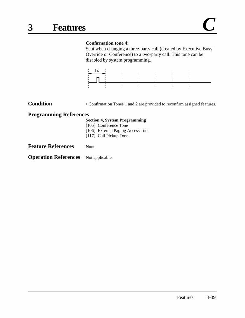
Features 3-39
3 Features CConfirmation tone 4: Sent when changing a three-party call (created by Executive BusyOverride or Conference) to a two-party call. This tone can bedisabled by system programming.
Condition • Confirmation Tones 1 and 2 are provided to reconfirm assigned features.
Programming ReferencesSection 4, System Programming[105] Conference Tone [106] External Paging Access Tone [117] Call Pickup Tone
Feature References None
Operation References Not applicable.
1 s

3-40 Features
D 3 Features
Data Line Security
Description Data Line Security is a feature that can be set at individualextensions. Once set, communication between the extension and theother party is protected from signals such as Call Waiting, HoldAlarm/Hold Recall and Executive Busy Override. Data equipmentor a facsimile may be connected to an extension jack so that theuser can perform data communications. During communication,Data Line Security maintains secure data transmission against tonesor interruptions from other extensions.
Conditions None
Programming ReferencesNo programming required.
Feature References Section 3, FeaturesCall WaitingExecutive Busy OverrideHold Alarm/Hold Recall
Operation Reference Telephone Features— User Manual Data Line Security
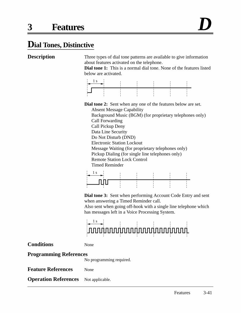
Features 3-41
3 Features D
Conditions None
Programming ReferencesNo programming required.
Feature References None
Operation References Not applicable.
Dial Tones, Distinctive
Description Three types of dial tone patterns are available to give informationabout features activated on the telephone.Dial tone 1: This is a normal dial tone. None of the features listedbelow are activated.
Dial tone 2: Sent when any one of the features below are set.Absent Message CapabilityBackground Music (BGM) (for proprietary telephones only)Call Forwarding Call Pickup Deny Data Line SecurityDo Not Disturb (DND) Electronic Station Lockout Message Waiting (for proprietary telephones only)Pickup Dialing (for single line telephones only)Remote Station Lock ControlTimed Reminder
Dial tone 3: Sent when performing Account Code Entry and sentwhen answering a Timed Reminder call.Also sent when going off-hook with a single line telephone whichhas messages left in a Voice Processing System.
1 s
1 s
1 s

3-42 Features
D 3 Features
Dial Type Selection
Description Allows an extension user to select the desired dialing mode for eachoutside (CO) line regardless of the originating extension (rotary ortone). There are three dialing modes available.
DTMF (Dual Tone Multi-Frequency) ModeThe dialing signal from an extension, either tone or rotary, isconverted to tone dialing. DTMF signals are transmitted to theoutside (CO) line.Pulse Dial (Rotary) ModeThe dialing signal from an extension, either tone or rotary, isconverted to rotary dialing. Rotary pulses are transmitted to theoutside (CO) line.Call Blocking ModeSet this mode for outside (CO) lines that can receive both toneand rotary dialing, but are under contract with the CentralOffice for rotary dialing only. When dialing to a line using atouch-tone telephone, only rotary dialing is sent to the CentralOffice.
Conditions • Extension users can temporarily convert the pre-assigned rotary dialingmode to DTMF mode (Pulse to Tone Conversion). DTMF mode cannotbe changed to rotary.
• Either DTMF or rotary dialing can be assigned for the DISA (DirectInward System Access) outgoing line. With DISA, pulse to toneconversion is not possible.
• If an outside (CO) line can receive both DTMF and pulse signals and iscontracted for DTMF with a Central Office, the DTMF mode should beselected for the line. If it is contracted for rotary mode, the CallBlocking mode should be selected for the line.
• If a line is assigned to the Pulse Dial mode, select an appropriate pulsespeed, if necessary.
• After a held call is retrieved, the dial mode returns to the one originallyprogrammed for the outside (CO) line.
Programming ReferencesSection 4, System Programming[401] Dial Mode[402] Pulse Speed Selection
Feature References Section 3, FeaturesEnd-to-End DTMF Signaling Pulse to Tone Conversion
(Tone Through)
Operation References Not applicable.

Features 3-43
3 Features DDirect In Lines (DIL)
Description Enables an incoming outside call to go directly to one extension.DIL places an incoming outside call to only one extension. Thisoutside (CO) line can be used by multiple extension users to makecalls, but can only be used by one extension to receive calls.DIL can have different destinations for the day, night and lunchmodes (Time Service).
Condition • If the Station Hunting feature is assigned to the destination extension,the call will be hunted.
Programming ReferencesSection 4, System Programming[414]–[416] Outside (CO) Line Mode — Day/Night/Lunch
Feature Reference Section 3, FeaturesStation Hunting
Operation References Not applicable.

3-44 Features
D 3 Features
Direct Inward System Access (DISA)
Description Allows an outside caller to access specific system features as if thecaller is an extension in the system. The caller can have directaccess to features such as:
• Placing an incoming call to an extension, operator or ringgroup. The caller also has the option of dialing the route for anextension using a one digit number (DISA built-in autoattendant number) via DISA calls.
• Calling an external party.One of the following must be selected to have direct access to thesefeatures: (1) None Security, (2) Trunk (Outside (CO) Line)Security, or (3) All Security. In None Security mode, any caller canmake outside or intercom calls. In Trunk (Outside (CO) Line)Security mode, a pre-assigned DISA security code must be enteredto make outside calls. In All Security mode, a pre-assigned DISAsecurity code must be entered to make both outside and intercomcalls. This prevents callers from making unauthorized calls.However, when making an outside call by Call Forwarding – toOutside (CO) Line, the call is allowed (exception).An Outgoing Message can be programmed for the DISA feature.When a caller reaches a DISA line, a message will greet the caller.Two different DISA messages can be recorded by the operator ormanager. For example, one message can be used in the day modeand the other in night mode, or they can be used for differentoutside (CO) lines. If an optional OGM/FAX Detection card is notinstalled, the caller will hear a beep instead of the outgoingmessage (the internal DISA).
Conditions • The following items are required for the DISA feature.(1) “DISA1” or “DISA2” must be assigned to outside (CO) line(s)
as the outside (CO) line mode.(2) An optional OGM/FAX Detection Card must be installed for
outgoing messages.(3) The DISA message(s) should be recorded by the operator or
manager.(2) and (3) are required for outgoing messages and fax detection.
• After the DISA Delayed Answer Time expires and a ringback tone isreturned to the caller, a DISA call will be answered. The caller can dialduring the message or after the tone.
• This system can store up to ten programmable DISA built-in autoattendant numbers. Each number is one digit.

Features 3-45
3 Features D• The DISA built-in auto attendant number may be the same as the first
digit of other numbers (extension number, etc.). To avoid confusion, thesystem waits for the second digit for a preprogrammed amount of time(default: 2 seconds). If the timer expires, the system will assume that thefirst digit is a DISA built-in auto attendant number.
• Only one OGM/FAX Detection card can be installed.• The DISA line can be used to originate outside calls if a security code (if
required) has been dialed.• This system can store up to four programmable DISA security codes.
Each code should be different.• The duration of outside-to-outside (CO-to-CO) line calls can be limited.
When the specified time expires, both lines are disconnected. A warningtone is sent to both parties 15 seconds before the time-limit.
• To detect the end of an outside-to-outside (CO-to-CO) line call, CPCSignal Detection can be assigned.
• If a wrong DISA security code is entered, three beeps will be heard. Thecall will be disconnected after three failed attempts.
Connection ReferenceSection 2, Installation2.4.2 Caller ID and OGM/FAX Detection Card Installation
Programming ReferencesSection 4, System ProgrammingTo enable the DISA feature[414]–[416] Outside (CO) Line Mode — Day/Night/Lunch[420] Calling Party Control (CPC Signal)[421] CPC Detection for Outgoing Calls[500] DISA Incoming Dialing Mode Selection[501] DISA Built-in Auto Attendant[502] OGM Mode Selection[503] FAX Connection[506] DISA Busy Mode[510] DISA No Dial Mode[511] DISA Security Type[512] DISA Security Codes[513] Cyclic Tone Detection[514] FAX Tone Detection[516] DISA Incoming Assignment[518] DISA Tone Selection after the Security CodeTo set DISA timer values[205] Outside-to-Outside (CO-to-CO) Line Duration Time limit[504] DISA Delayed Answer Time[505] DISA Waiting Time After OGM[517] DISA AA Wait Time
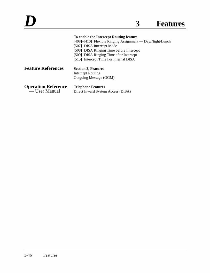
3-46 Features
D 3 FeaturesTo enable the Intercept Routing feature[408]–[410] Flexible Ringing Assignment — Day/Night/Lunch[507] DISA Intercept Mode[508] DISA Ringing Time before Intercept[509] DISA Ringing Time after Intercept[515] Intercept Time For Internal DISA
Feature References Section 3, FeaturesIntercept RoutingOutgoing Message (OGM)
Operation Reference Telephone Features— User Manual Direct Inward System Access (DISA)

Features 3-47
3 Features D
Busy tone
An outside line call is made.
The caller reaches the DISA line.
Is a securitycode required?
A number is dialed.
Make an outside call.
No
One short beep@@@@@@@@e?@@@@@@@@e?@@h?@@h?@@h?@@h?@@h?@@h?
@@@@@@@@e?@@@@@@@@?e@@@@@@@@e?@@@@@@@@?e@@@@@@@@e?@@@@@@@@?e@@@@@@@@e?@@@@@@@@?e@@@@@@@@e?@@@@@@@@?e@@@@@@@@e?@@@@@@@@?e@@@@@@@@e?@@@@@@@@e?@@@@@@@@?e@@@@@@@@e?@@@@@@@@?e@@@@@@@@e?@@@@@@@@?e@@@@@@@@e?@@@@@@@@?e@@@@@@@@e?@@@@@@@@?e@@@@@@@@e?@@@@@@@@?e@@@@@@@@e?
@@@@@@@@@@@@@@@@@@@@@@@@@@@@
@@@@@@@@@@@@@@@@
@@@@@@@@@@@@@@@@
?@@?@@?@@?@@?@@?@@
?@@@@@@@@?@@@@@@@@
?@@@@@@@@?e@@@@@@@@e?@@@@@@@@?e@@@@@@@@e?@@@@@@@@?e@@@@@@@@e?@@@@@@@@?e@@@@@@@@e?@@@@@@@@?e@@@@@@@@e?@@@@@@@@?e@@@@@@@@e?@@@@@@@@?@@@@@@@@?e@@@@@@@@e?@@@@@@@@?e@@@@@@@@e?@@@@@@@@?e@@@@@@@@e?@@@@@@@@?e@@@@@@@@e?@@@@@@@@?e@@@@@@@@e?@@@@@@@@?e@@@@@@@@e?@@@@@@@@
@@g@@g@@g@@g@@g@@g@@@@@@@@@@@@@@@@
@@@@@@@@@@@@@@@@
@@@@@@@@@@@@@@@@
Nothing is dialed. The call is sent tothe fax extension.
Yes
The securitycode is entered.
Is Intercept Routing employed?
The call is sent toanother extension.
Disconnect.
NoYes
Disconnect.
Answered.
Is Intercept Routing employed?
Disconnect.
NoYes
The call is not answered.
The call is notanswered.
The code is correct.
Disconnect.
What is the DISABusy Mode?
Answered. The call is notanswered.
*1
*2
*3
*13
*14
CNG toneCyclic toneor CPC signal
*4
What is the security type?
Trunk or None
Disconnect.All
*15
*18
*5
The call reaches the destination. Reorder tone
*6
*7
The destinationextension(s) is(are) busy.
*8
B
Answered.
The call is notanswered for40 seconds.
*16
*17
*11
*9
*10
Call Waiting DISA2
*12
Disconnect.
Busy tone
Goes to
Goes to
Disconnect
Goes to
OGM@@@@@@@@e?@@@@@@@@e?@@h?@@h?@@h?@@h?@@h?@@h?
@@@@@@@@e?@@@@@@@@?e@@@@@@@@e?@@@@@@@@?e@@@@@@@@e?@@@@@@@@?e@@@@@@@@e?@@@@@@@@?e@@@@@@@@e?@@@@@@@@e?@@@@@@@@?e@@@@@@@@e?@@@@@@@@?e@@@@@@@@e?@@@@@@@@?e@@@@@@@@e?@@@@@@@@?e@@@@@@@@e?
@@@@@@@@@@@@@@@@@@@@@@@@@@@@
@@@@@@@@@@@@@@@@
@@@@@@@@@@@@@@@@
?@@?@@?@@?@@?@@?@@
?@@@@@@@@?@@@@@@@@
?@@@@@@@@?e@@@@@@@@e?@@@@@@@@?e@@@@@@@@e?@@@@@@@@?e@@@@@@@@e?@@@@@@@@?e@@@@@@@@e?@@@@@@@@?@@@@@@@@?e@@@@@@@@e?@@@@@@@@?e@@@@@@@@e?@@@@@@@@?e@@@@@@@@e?@@@@@@@@?e@@@@@@@@e?@@@@@@@@
@@g@@g@@g@@g@@g@@g@@@@@@@@@@@@@@@@
@@@@@@@@@@@@@@@@
@@@@@@@@@@@@@@@@
The otherOGM is heard.A
The call is sent toanother extension.
A
B
C
C
Answered.
With optional OGM/FAX Detection Card
Without optionalOGM/FAX Detection Card(Internal DISA)
The code is incorrect.
One shortbeep
Flow chart of possible cases and results for DISA calls
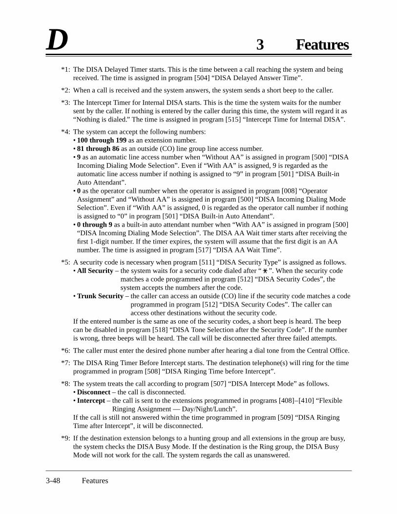
3-48 Features
D 3 Features*1: The DISA Delayed Timer starts. This is the time between a call reaching the system and being
received. The time is assigned in program [504] “DISA Delayed Answer Time”.
*2: When a call is received and the system answers, the system sends a short beep to the caller.
*3: The Intercept Timer for Internal DISA starts. This is the time the system waits for the numbersent by the caller. If nothing is entered by the caller during this time, the system will regard it as“Nothing is dialed.” The time is assigned in program [515] “Intercept Time for Internal DISA”.
*4: The system can accept the following numbers:• 100 through 199 as an extension number.• 81 through 86 as an outside (CO) line group line access number.• 9 as an automatic line access number when “Without AA” is assigned in program [500] “DISA
Incoming Dialing Mode Selection”. Even if “With AA” is assigned, 9 is regarded as theautomatic line access number if nothing is assigned to “9” in program [501] “DISA Built-inAuto Attendant”.
• 0 as the operator call number when the operator is assigned in program [008] “OperatorAssignment” and “Without AA” is assigned in program [500] “DISA Incoming Dialing ModeSelection”. Even if “With AA” is assigned, 0 is regarded as the operator call number if nothingis assigned to “0” in program [501] “DISA Built-in Auto Attendant”.
• 0 through 9 as a built-in auto attendant number when “With AA” is assigned in program [500]“DISA Incoming Dialing Mode Selection”. The DISA AA Wait timer starts after receiving thefirst 1-digit number. If the timer expires, the system will assume that the first digit is an AAnumber. The time is assigned in program [517] “DISA AA Wait Time”.
*5: A security code is necessary when program [511] “DISA Security Type” is assigned as follows.• All Security – the system waits for a security code dialed after “ ”. When the security code
matches a code programmed in program [512] “DISA Security Codes”, thesystem accepts the numbers after the code.
• Trunk Security – the caller can access an outside (CO) line if the security code matches a codeprogrammed in program [512] “DISA Security Codes”. The caller canaccess other destinations without the security code.
If the entered number is the same as one of the security codes, a short beep is heard. The beepcan be disabled in program [518] “DISA Tone Selection after the Security Code”. If the numberis wrong, three beeps will be heard. The call will be disconnected after three failed attempts.
*6: The caller must enter the desired phone number after hearing a dial tone from the Central Office.
*7: The DISA Ring Timer Before Intercept starts. The destination telephone(s) will ring for the timeprogrammed in program [508] “DISA Ringing Time before Intercept”.
*8: The system treats the call according to program [507] “DISA Intercept Mode” as follows.• Disconnect – the call is disconnected.• Intercept – the call is sent to the extensions programmed in programs [408]–[410] “Flexible
Ringing Assignment — Day/Night/Lunch”.If the call is still not answered within the time programmed in program [509] “DISA RingingTime after Intercept”, it will be disconnected.
*9: If the destination extension belongs to a hunting group and all extensions in the group are busy,the system checks the DISA Busy Mode. If the destination is the Ring group, the DISA BusyMode will not work for the call. The system regards the call as unanswered.

Features 3-49
3 Features D*10: The DISA Busy Mode is selected in program [506] “DISA Busy Mode”. There are three modes
as follows:• Disconnect – the caller hears a busy tone and the call is disconnected.• Call Waiting – the destination extension hears the call waiting tone if they have enabled Call
Waiting.• DISA2 – if “MODE2” is assigned in program [502] “OGM Mode Selection” and a message is
recorded in OGM2, the caller hears the message and the system waits for the newdestination.
*11: The DISA Ring Timer Before Intercept starts. The destination telephone(s) will ring for the timeprogrammed in program [508] “DISA Ringing Time before Intercept”.
*12: In this case, the system disregards the security type and does not accept the line access code. Ifnothing is recorded in OGM2, the caller will hear a busy tone and the call is disconnected.
*13: The OGM is sent to the caller according to programs [414]–[416] “Outside (CO) Line Mode –Day/Night/Lunch” and [502] “OGM Mode Selection”. If an OGM is not recorded, the DISAWait Timer After OGM programmed in program [505] “DISA Waiting Time after OGM” willstart immediately.When the system detects a CNG tone while the OGM is being sent, the call is sent to the FAXextension. When the system detects a cyclic tone or a CPC signal while the OGM is being sent,the call is disconnected.
*14: The DISA Wait Timer After OGM starts. The system waits for a number from the caller duringthe time programmed in program [505] “DISA Waiting Time after OGM”. When the systemdetects a CNG tone during the programmed time, the call is sent to the FAX extension. When thesystem detects a cyclic tone or a CPC signal during the programmed time, the call isdisconnected.
*15: After the DISA Wait Timer After OGM or the Intercept Timer for Internal DISA expires, thesystem regards that nothing was dialed .
*16: The system treats the call according to program [510] “DISA No Dial Mode” as follows.• Disconnect – the call is disconnected.• Intercept – the call is sent to the extensions programmed in programs [408]–[410] “Flexible
Ringing Assignment — Day/Night/Lunch”. If all of the extensions are assigned to“Disable”, the call will be disconnected.
*17: The DISA Ring Timer After Intercept starts. The destination telephone(s) will ring for the timeprogrammed in program [509] “DISA Ringing Time after Intercept”. If the call is not answeredduring the programmed time, the call will be disconnected.
*18: The FAX extension assigned in program [503] “FAX Connection” receives the call. When theextension is busy, the system sends a busy tone to the Fax. If the call is not answered after40 seconds, the call will be disconnected.Program [514] “Fax Tone Detection” sets how many times the CNG tone must be detected beforethe system recognizes the incoming signal as facsimile data.

3-50 Features
D 3 Features
Display, Call Information
Description A display proprietary telephone shows the user the following callinformation.
Extension number and nameThese are shown when calling or when called by an extensionuser, during an established intercom call, and while on-hook.Display example: 102: Smith
Dialed telephone numberThis is shown when dialing the telephone number.Display example: 91234567890
Number or name of the callerThese are shown if the Caller ID feature is available.Display examples: 1234567890
PanasonicCall duration
This is shown during an established outside call. The displayremains for five seconds after the call is finished.Display example: CO 2 0:02'28
Conditions • Extension numbers and names are programmable. If an extension nameis not stored, only the extension number will be displayed.
• The display does not show the intercom call duration.• The outgoing outside call duration starts when the programmable timer
expires.
Programming ReferencesSection 4, System Programming[009] Extension Number Assignment[204] Call Duration Count Start Time[604] Extension Name Setting
Feature Reference Section 3, FeaturesCaller ID
Operation References Not applicable.
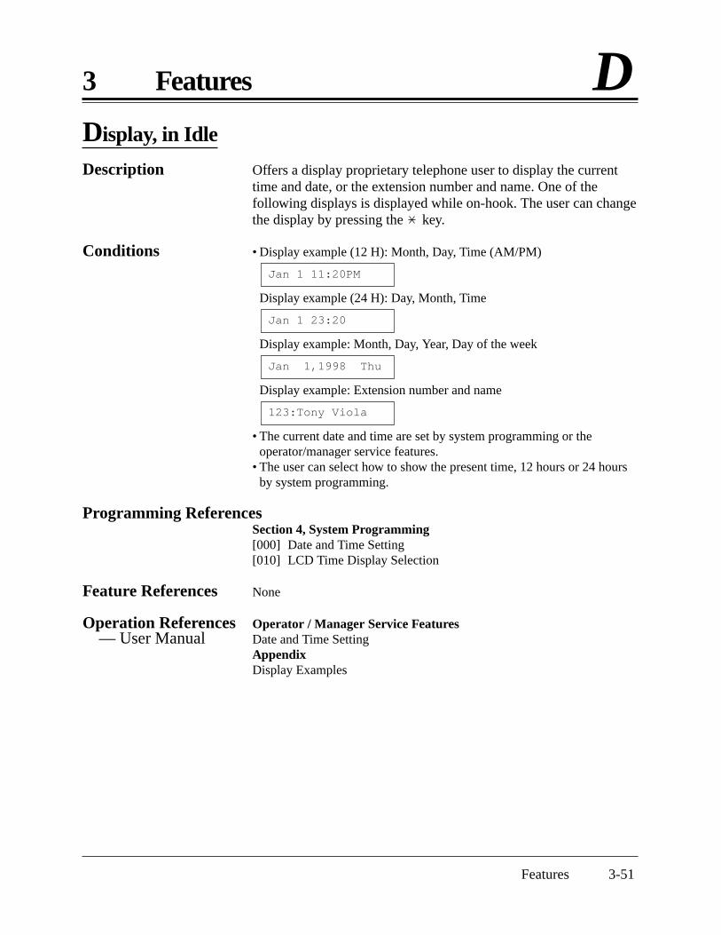
Features 3-51
3 Features DDisplay, in Idle
Description Offers a display proprietary telephone user to display the currenttime and date, or the extension number and name. One of thefollowing displays is displayed while on-hook. The user can changethe display by pressing the key.
Conditions • Display example (12 H): Month, Day, Time (AM/PM)
Display example (24 H): Day, Month, Time
Display example: Month, Day, Year, Day of the week
Display example: Extension number and name
• The current date and time are set by system programming or theoperator/manager service features.
• The user can select how to show the present time, 12 hours or 24 hoursby system programming.
Programming ReferencesSection 4, System Programming[000] Date and Time Setting[010] LCD Time Display Selection
Feature References None
Operation References Operator / Manager Service Features— User Manual Date and Time Setting
AppendixDisplay Examples
123:Tony Viola
Jan 1,1998 Thu
Jan 1 23:20
Jan 1 11:20PM

3-52 Features
D 3 Features
Display Contrast Adjustment
Description Allows a display proprietary telephone user to adjust the displaycontrast.
Condition • A lever on the telephone (CONTRAST selector) is used to select one ofthree available levels.
Programming ReferenceConfiguration RRRRRRRRRRRRR User ManualInitial Settings — Display Contrast Adjustment (KX-T7030 and
KX-T7130 only)
Feature References None
Operation References Not applicable.
Display, Self-Extension Number
Description Allows a display proprietary telephone user to display their ownjack number and extension number in the station programmingmode.
Condition • Display exampleIf the jack number is 02 and the extension number is 102:
Programming ReferenceStation Programming RRRRRRRRRR User ManualSelf-Extension Number Confirmation (KX-T7030 and KX-T7130 only)
Feature References None
Operation References Not applicable.
Jack02<=>EXT102
Features 3-53
3 Features D
Do Not Disturb (DND) Override
Description Allows a pre-assigned extension user to call another user who hasset the Do Not Disturb feature. Dialing “2” enables the caller tooverride DND programmed on the called extension’s telephone andforces the telephone to ring.
Condition • System programming determines which extension users can performDND Override.
Programming ReferenceSection 4, System Programming[609] Do Not Disturb Override
Feature Reference Section 3, FeaturesDo Not Disturb (DND)
Operation Reference Telephone Features— User Manual Do Not Disturb (DND) Override
Do Not Disturb (DND)
Description Allows an extension user to appear busy to incoming outside orintercom calls. This can be set or canceled by the extension user.
Conditions • If a proprietary telephone (PT) is not supplied with the FWD/DNDbutton, it can be assigned to a flexible CO button.
• DND does not work for the following calls: hold recalls or the TimedReminder alarm.
• A PT user in DND mode can answer a call by pressing thecorresponding flashing button.
• An extension in DND mode can be called by other extension users whoare allowed to override DND in program [609] “Do Not DisturbOverride”.
• If the Call Forwarding feature has already been set, setting the DNDfeature will cancel Call Forwarding.
Programming ReferenceStation Programming RRRRRRRRRR User Manual Flexible Button Assignment – FWD/DND Button
Feature Reference Section 3, FeaturesDo Not Disturb (DND) Override
Operation Reference Telephone Features— User Manual Do Not Disturb (DND)

3-54 Features
D 3 Features
Door Opener
Description Allows extension users to unlock the door for a visitor from theirtelephone. The door can be unlocked by extension users who havebeen programmed to enable this feature.
Conditions • An optional Doorphone/Door Opener card must be installed.• A user-supplied door opener must be installed to the door to be opened.
Four door openers can be installed.• The door opener will open the door even if a doorphone is not installed.• The user can modify the door opener timer through system
programming.
Connection ReferenceSection 2, Installation2.4.3 Doorphone and Door Opener Connection
Programming ReferencesSection 4, System Programming[703]–[705] Door Opener Assignment — Day/Night/Lunch[709] Door Opener time
Feature Reference Section 3, FeaturesDoorphone Call
Operation Reference Telephone Features— User Manual Door Opener

Features 3-55
3 Features DDoorphone Call
Description If a visitor presses the doorphone button, pre-assigned extensionswill be called. The extension who answers the call can talk to thevisitor. Any extension user can call a doorphone. The doorphonesare also used for the Room Monitor feature.
Conditions • An optional Doorphone/Door Opener card must be installed.• Four doorphones can be installed.• The extensions which can receive calls from each doorphone during the
day, night and lunch modes must be programmed.• If an extension user does not answer an incoming doorphone call within
a programmed period of time, the ringing will stop and be canceled.• A programmed extension user can open the door from the telephone to
let the visitor in (Door Opener). This requires a user-supplied dooropener.
• An access tone can be programmed to be sent to the monitoreddoorphone before monitoring starts.
• The ringing tone from the doorphone call is programmable.• Doorphone 1 and Doorphone 2 cannot receive calls simultaneously.
When one is in use, an extension user cannot have a conversation withthe other. This is the same for Doorphone 3 and Doorphone 4.
Connection ReferenceSection 2, Installation2.4.3 Doorphone and Door Opener Connection
Programming ReferencesSection 4, System Programming[700]–[702] Doorphone Ringing Assignment — Day/Night/Lunch[706] Door Ringing/Tone Pattern Selection[707] Doorphone Access Tone Selection[708] Doorphone Ringing Time
Feature References Section 3, FeaturesDoor OpenerRoom Monitor
Operation References Telephone Features— User Manual Doorphone Call
Room Monitor

3-56 Features
D 3 Features
DSS Console (KX-T7040)
Description The Direct Station Selection (DSS) Console provides direct accessto stations, a busy lamp display, as well as 16 PF (ProgrammableFeature) buttons.The DSS Console must be programmed to work with a proprietarytelephone (PT). System programming assigns the jack numbers ofthe DSS Console and its associated PT.Up to two consoles can be installed per system. A PT can be pairedwith up to two DSS Consoles. The paired telephone user can carryout the following operations using the DSS Console.
• Direct access to an extension (Direct Station Selection)• Quick access to an external party (One-Touch Dialing)• Easy transfer of an outside call to an extension (The
programmable One-Touch Transfer feature provides thissimple operation.)
• Quick access to a system feature• Changing the time (Day/Night/Lunch) service easily
(Day/Night/Lunch Button Assignment) — only for anOperator and Manager
• Set and cancel the remote station lock control feature (StationLock Button Assignment) — only for an Operator andManager
The above features are activated simply by pressing the buttons onthe console which were pre-programmed as feature buttons.A DSS Console has two types of buttons as shown below.
DSS Console KX-T7040
DSS buttons
PF buttons

Features 3-57
3 Features DDSS (Direct Station Selection) buttons: Used to accessextensions, change the time (day/night/lunch) service, and set andcancel the Remote Station Lock Control feature. Each button isprogrammed to correspond to an extension. Pressing a buttonallows the user to call the corresponding extension. Each buttonalso has an indicator (Busy Lamp Field), which shows the currentstate of the corresponding extension as shown in the Table below.
To meet the user’s various needs, DSS buttons can be changed tothe other feature buttons.
PF (Programmable Feature) buttons marked as F1 throughF16: These buttons have no default settings. The paired telephoneuser can program the buttons for other feature buttons.
Conditions • Programming the DSS and PF buttons can be done only from the pairedtelephone using station programming.
• If the extension number assigned to a DSS button is changed to anothernumber, the DSS button automatically changes to the new number. (Re-programming is not necessary.)
• Indicating the FWD/DND status of corresponding extensions using aDSS button indication is programmable.
Connection ReferenceSection 2, Installation2.3.4 Extension Connection
Programming ReferencesSection 4, System Programming[003] DSS Console Port Assignment[004] Paired Telephone Assignment for DSS Console[112] DSS Console Indication ModeStation Programming RRRRRRRRRR User ManualFlexible Button AssignmentDSS Console Features RRRRRRRRRR User ManualStation Programming
Feature References Section 3, FeaturesButton, Flexible Remote Station Lock ControlOne-Touch Transfer Using Time (Day/Night/Lunch) Service
a DSS Button
Operation Reference DSS Console Features— User Manual
LightOffOn
Flashing*
State of extensionIdle
BusyFWD/DND is enabled.
Busy Lamp Field Table
*: When program [112] isassigned to “Enable”,the indicator will flash.

3-58 Features
E 3 Features
Electronic Station Lockout
Description Allows an extension user to lock their station so that other userscannot make outgoing outside calls. Any 4-digit code can be usedto lock the station. The same code is used to unlock it. The manageror operator can cancel this feature for all extensions.
Conditions • Making intercom calls and receiving intercom or outside calls arepermitted on the locked station.
• Remote Station Lock Control overrides Electronic Station Lockout. Ifthe operator or manager sets Remote Station Lock on a station that hasalready been locked by the station user, the user cannot unlock it.
• A toll restriction class can be assigned for this feature. Certain types ofoutgoing outside calls are permitted depending on the assigned tollrestriction class.
Programming ReferencesSection 4, System Programming[108] Flash Mode for a Station Locked Extension[312] Toll Restriction — Station Lock Boundary Class
Feature References Section 3, FeaturesRemote Station Lock ControlToll Restriction — Station Lock Boundary Class
Operation References Telephone Features— User Manual Electronic Station Lockout
Operator/Manager FeaturesElectronic Station Lockout — CANCEL ALL

Features 3-59
3 Features EEmergency Call
Description Allows the extension user to call a pre-assigned emergency numberregardless of any restrictions.
Conditions • Up to five emergency numbers can be stored. “911” is already stored bythe default setting.
• An emergency number can be dialed even in the following cases:— in Account Code – Verify – All and Forced modes,— in any toll restriction COS number, and— in Electronic Station Lockout.
Programming ReferenceSection 4, System Programming[309] Emergency Dial Number Set
Feature References None
Operation Reference Telephone Features— User Manual Emergency Call
End-to-End DTMF Signaling (Tone Through)
Description DTMF signaling is required for access to special network servicesoffered by some telephone companies. This system allows aproprietary telephone user to send DTMF signals to the line duringa call in progress.
Conditions • If the line dial type is assigned to DTMF, the Tone Through mode isestablished automatically after the dialing sequence is finished and thecall is established.
• If the line dial type is assigned to pulse, the Tone Through mode isestablished after the dialing sequence is finished and the “ #” buttonsare pressed (Pulse to Tone Conversion).
Programming Reference[118] Pulse Restriction
Feature References Section 3, FeaturesDial Type SelectionPulse to Tone Conversion
Operation References Not applicable.
3-60 Features
E 3 Features
Executive Busy Override – Extension
Description Allows a pre-assigned extension user to interrupt an existingextension call, either between two inside parties or an external andinside party, to establish a three-party conference call. Extensionusers can prevent this feature from being executed by anotherextension user (Executive Busy Override Deny).
Conditions • System programming determines which extension users can performExecutive Busy Override.
• This feature will not work if the extension has set Executive BusyOverride Deny or Data Line Security.
• When a three-party call is changed to a two-party call or vice versa, aconfirmation tone is sent to all three parties. This tone can be disabledby system programming.
Programming ReferencesSection 4, System Programming[105] Conference Tone[608] Executive Busy Override
Feature References Section 3, FeaturesConferenceData Line Security
Operation Reference Telephone Features— User Manual Executive Busy Override — Extension
Features 3-61
3 Features EExecutive Busy Override – Outside (CO) Line
Description Allows a proprietary telephone user to interrupt an existing outsidecall, either between two external parties or an external and insideparty, to establish a three-party conference call. Extension users canprevent this feature from being executed by another extension user(Executive Busy Override Deny).
Conditions • System programming determines which extension users can performExecutive Busy Override.
• This feature will not work if the extension has set Executive BusyOverride Deny or Data Line Security.
• When a three-party call is changed to a two-party call or vice versa, aconfirmation tone is sent to all three parties. This tone can be disabledby system programming.
Programming ReferencesSection 4, System Programming [105] Conference Tone[608] Executive Busy Override
Feature References Section 3, FeaturesConferenceData Line Security
Operation Reference Telephone Features — User Manual Executive Busy Override — Outside (CO) Line

3-62 Features
E 3 Features
Extension Group
Description The system supports eight extension groups. Any member of anextension group can pick up a call directed to another groupmember (Group Call Pickup) or can make a voice announcement toanother group member (Paging – Group). In addition, the StationHunting feature can be enabled for each extension group. A DISAring group is a specific extension group.
Condition • Each extension should belong to an extension group, but cannot belongto more than one group.
Programming ReferenceSection 4, System Programming[600] Extension Group Assignment
Feature References Section 3, FeaturesCall Pickup, Group Paging – GroupDirect Inward System Access (DISA) Station Hunting
Operation References Not applicable.
Features 3-63
3 Features EExternal Feature Access
Description Allows an extension user to access the features of a host PBX orCentral Office, such as Call Waiting, etc. This is performed byputting the current party on hold and sending a flash signal.
Conditions • This feature is effective only during an outside call. However, if theFLASH feature (Disconnection signal) is activated by the user, thisfeature will not work.
• The flash time must be assigned as required by the host PBX or outside(CO) line.
• With a proprietary telephone, the FLASH button is used to perform thisfeature . With a single line telephone, flashing the hookswitch andentering the feature number are used to perform this feature .
• During outside calls, a FLASH stored in System Speed Dialing,Personal Speed Dialing or One-Touch Dialing features as ExternalFeature Access, not as a Flash.
Programming ReferencesSection 4, System Programming[110] Flash Key Mode[418] Flash Time
Feature References Section 3, Features FlashHost PBX Access
Operation Reference Telephone Features— User Manual External Feature Access
3-64 Features
F 3 Features
Facsimile Detection
Description When the system receives a facsimile transmission signal by DirectInward System Access (DISA), it automatically connects thespecified facsimile extension.
Conditions • The extension which can receive facsimile data must be assigned bysystem programming.
• An optional OGM/FAX Detection Card must be installed.
Connection ReferenceSection 2, Installation2.4.2 Caller ID and OGM/FAX Detection Card Installation
Programming ReferencesSection 4, System Programming[503] FAX Connection[514] FAX Tone Detection
Feature Reference Section 3, FeaturesDirect Inward System Access (DISA)
Operation References None
Flash
Description Allows a proprietary telephone user to disconnect the current calland originate another call without hanging up by using the FLASHbutton.
Conditions • System programming may be required to perform this feature properly.• Pressing the FLASH button re-starts the conversation duration, outputs
an SMDR record and checks the toll restriction COS number again.
Programming ReferencesSection 4, System Programming[110] Flash Key Mode[418] Flash Time
Feature Reference Section 3, FeaturesExternal Feature Access
Operation Reference Telephone Features — User Manual Flash
Features 3-65
3 Features HHandset/Headset Selection
Description The system supports the use of headsets on proprietary telephones(KX-T7030 and KX-T7130 only).
Conditions • The headset is an user supplied item.• To set the headset mode on a PT, use the handset/headset selector
provided on the set and/or the headset.
Programming ReferencesNo programming required.
Feature References None
Operation Reference Configuration —User Manual Initial Settings
Hands-free Answerback
Description Allows the speakerphone proprietary telephone user to talk to acaller without lifting the handset, if the user has set the hands-freeanswerback mode. If the user receives an intercom call in thismode, a hands-free conversation is established immediately afterthe user hears a beep and the caller hears a confirmation tone.
Conditions • The hands-free answerback mode is set or canceled by pressing theAUTO ANSWER button.
• This feature does not work for calls from outside parties or doorphonecalls.
Programming ReferencesNo programming required.
Feature References None
Operation Reference Telephone Features —User Manual Hands-free Answerback
3-66 Features
H 3 Features
Hands-free Operation
Description Allows a proprietary telephone user to dial and talk to the otherparty without lifting the handset. Pressing the appropriate buttonprovides the hands-free mode.
Conditions • This feature can be utilized by pressing one of the following buttonswhen the SP-PHONE/MONITOR button indicator is off:SP-PHONE button, MONITOR button, INTERCOM button, or CObutton.
• The KX-T7050 and the KX-T7055 can be used for hands-free dialingoperations, etc., but cannot be used for a hands-free conversation.
Programming ReferencesNo programming required.
Feature References None
Operation Reference Telephone Features —User Manual Hands-free Operation
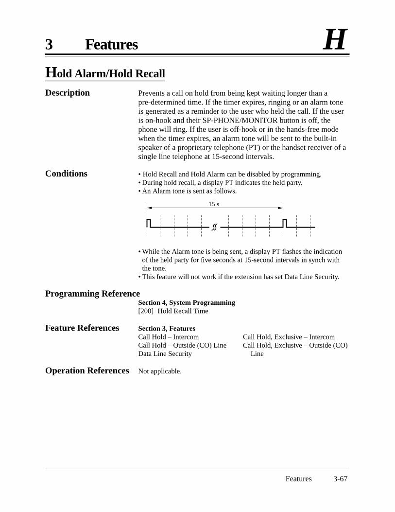
Features 3-67
3 Features HHold Alarm/Hold Recall
Description Prevents a call on hold from being kept waiting longer than apre-determined time. If the timer expires, ringing or an alarm toneis generated as a reminder to the user who held the call. If the useris on-hook and their SP-PHONE/MONITOR button is off, thephone will ring. If the user is off-hook or in the hands-free modewhen the timer expires, an alarm tone will be sent to the built-inspeaker of a proprietary telephone (PT) or the handset receiver of asingle line telephone at 15-second intervals.
Conditions • Hold Recall and Hold Alarm can be disabled by programming.• During hold recall, a display PT indicates the held party.• An Alarm tone is sent as follows.
• While the Alarm tone is being sent, a display PT flashes the indicationof the held party for five seconds at 15-second intervals in synch withthe tone.
• This feature will not work if the extension has set Data Line Security.
Programming ReferenceSection 4, System Programming[200] Hold Recall Time
Feature References Section 3, FeaturesCall Hold – Intercom Call Hold, Exclusive – IntercomCall Hold – Outside (CO) Line Call Hold, Exclusive – Outside (CO)Data Line Security Line
Operation References Not applicable.
15 s

3-68 Features
H 3 Features
Host PBX Access
Description The system may be installed behind an existing host PBX. This isperformed by connecting a line from the host to an outside (CO)line in the Advanced Hybrid System.
Conditions • A Host PBX Access Code is required to access outside (CO) lines of thehost PBX.
• A pause, if programmed, can be inserted between the user-dialed HostPBX Access Code and the digits which follow (Automatic PauseInsertion). Program the pause time required by the Host PBX for thatoutside (CO) line group.
• Access to the host PBX during a conversation is also possible (ExternalFeature Access).
Programming ReferencesSection 4, System Programming[403] Host PBX Access Codes[417] Pause Time
Feature References Section 3, FeaturesExternal Feature AccessPause Insertion, Automatic
Operation References Not applicable.

Features 3-69
3 Features IIntercept Routing
Description Provides automatic redirection of incoming outside calls via DISA.There are two types of Intercept Routing.
Condition • The Intercept Routing feature works in the following cases.(1) When nothing is dialed after the dial tone or OGM is sent to the
caller.(2) When the call is not answered within a programmed time. This is
called Intercept Routing — No Answer (IRNA).
Programming ReferencesSection 4, System Programming[408]–[410] Flexible Ringing Assignment — Day/Night/Lunch[507] DISA Intercept Mode[508] DISA Ringing Time before Intercept[509] DISA Ringing Time after Intercept[510] DISA No Dial Mode
Feature References None
Operation References Not applicable.

3-70 Features
I 3 Features
Intercom Calling
Description Allows an extension user to call another extension user within thesystem.
Conditions • Extension numbers are assigned to all extensions by systemprogramming.
• Names can be given to extension numbers by system programming. Anextension number and a name, if programmed, will be shown on thedisplay PT during an intercom call.
• DSS buttons permit one-touch access to an extension and provide theBusy Lamp Field.
• After dialing an extension number, the user will hear one of thefollowing.
Ringback tone: indicates the other extension is being called.Busy tone: indicates the other extension is busy.Do Not Disturb tone: indicates the other extension has assignedDND.
• A proprietary telephone user can select one of the Intercom Alert modes,Voice Call or Tone Call. Voice Call informs the called party of anincoming call with the calling party’s voice, while Tone Call uses a ringtone. The calling party can only switch the pre-set mode at the calledextension, from Voice Call to Tone Call.
Programming ReferencesSection 4, System Programming[009] Extension Number Assignment[604] Extension Name SettingStation Programming RRRRRRRRRR User Manual Flexible Button Assignment – Direct Station Selection (DSS) Button Intercom Alert Assignment
Feature References Section 3, FeaturesBusy Lamp FieldButton, Direct Station Selection (DSS)
Operation References Telephone Features—User Manual Intercom Calling
Switching to Tone Alert

Features 3-71
3 Features LLED Indication, Intercom
Description The LED (Light Emitting Diode) indicator of the INTERCOMbutton indicates the line condition using a variety of lightingpatterns. This allows the user to see the current state of the intercomline. The table below shows the lighting patterns and the intercomline conditions.
Conditions None
Programming ReferencesNo programming required.
Feature Reference Section 3, FeaturesBusy Lamp Field
Operation References Not applicable.
INTERCOM Button
Off
Green On
Flashing green slowly
Flashing green moderately
Flashing green rapidly
INTERCOM Status
Idle
Intercom call / Conference established
Intercom call on hold
Intercom call exclusive hold
Incoming intercom / Doorphone call

1 s
3-72 Features
L 3 Features
LED Indication, Outside (CO) Line
Description The LED (Light Emitting Diode) indicators of the buttonsassociated with outside (CO) lines show the line conditions using avariety of lighting patterns. This allows the user to see which linesare idle and which lines are in use. The table below shows thelighting patterns for different line conditions.
Condition • A slow flashing red indication only appears on a S-CO button.
Programming ReferencesStation Programming RRRRRRRRRR User ManualFlexible Button Assignment – Group-CO (G-CO) Button,
Other-CO (O-CO) Button, Single-CO (S-CO) Button
Feature References Section 3, FeaturesButton, Group-CO (G-CO)Button, Other-CO (O-CO)Button, Single-CO (S-CO)
Operation References Not applicable.
LED Indicator
Off
Green On
Flashing green slowly
Flashing green moderately
Flashing red rapidly
Red On
Flashing red slowly
Outside (CO) Line Status
Idle
I-use
I-hold
I-Exclusive Hold / Outside-to-Outside (CO-to-CO) Line call /Unattended Conference
Incoming call
Other-use
Other-hold
Flashing light patterns
Flashing slowly
Flashing moderately
Flashing rapidly

Features 3-73
3 Features LLimited Call Duration
Description Limited Call Duration is a system programmable feature thatdisconnects an outside-to-outside (CO-to-CO) line call when aspecific timer expires. A warning tone is sent to the caller15 seconds before the time-limit.
Conditions None
Programming ReferenceSection 4, System Programming[205] Outside-to-Outside (CO-to-CO) Line Duration Time Limit
Feature References Section 3, FeaturesCall Forwarding – to an Outside (CO) LineCall Transfer, Screened – to an Outside (CO) LineConference, UnattendedDirect Inward System Access (DISA)
Operation References Not applicable.

3-74 Features
L 3 Features
Line Access, Automatic
Description Allows an extension user to dial the automatic line accessnumber (9) and access an idle line from the assigned outside (CO)lines.
Conditions • Each extension is subject to system programming items to accessoutside (CO) lines.
• This feature requires a CO button (G-CO, O-CO or S-CO) assignmenton a proprietary telephone (PT). Dialing the line access code selects aCO button on a PT according to the priority.
S-CO > G-CO (on a hunted outside (CO) line)• If Idle Line Preference – Outgoing is set on the telephone, the user can
access an idle line only by going off-hook.• After an outside (CO) line is seized, the system waits for a programmed
time before dialing.
Programming ReferencesSection 4, System Programming[206] Dialing Start Time[400] Outside (CO) Line Connection Assignment[405]–[407] Flexible Outward Dialing Assignment — Day/Night/Lunch[419] Automatic Designated Outside (CO) Line Access
Feature Reference Section 3, FeaturesOutside (CO) Line Connection Assignment – Outgoing
Operation Reference Telephone Features— User Manual Outward Dialing – Line Access, Automatic

Features 3-75
3 Features LLine Access, Direct
Description Allows a proprietary telephone user to select an outside (CO) lineby pressing an idle CO button, which automatically establishes thehands-free operation mode and allows the user to perform On-HookDialing. The user does not need to press the SP-PHONE button,MONITOR button, or lift the handset.
Conditions • There are three types of CO buttons which can be programmed at anextension: Single-CO button, Group-CO button and Other-CO button.
• Each extension is subject to system programming items to accessoutside (CO) lines.
• After an outside (CO) line is seized, the system waits for a programmedtime before dialing.
Programming ReferencesSection 4, System Programming[206] Dialing Start Time[400] Outside (CO) Line Connection Assignment[405]–[407] Flexible Outward Dialing Assignment — Day/Night/LunchStation Programming RRRRRRRRRR User Manual Flexible Button Assignment – Group-CO (G-CO) Button,
Other-CO (O-CO) Button, Single-CO (S-CO) Button
Feature References Section 3, FeaturesButton, Group-CO (G-CO)Button, Other-CO (O-CO)Button, Single-CO (S-CO)Outside (CO) Line Connection Assignment – Outgoing
Operation Reference Telephone Features — User Manual Outward Dialing – Line Access, Automatic,
Line Access, Individual,Line Access, Outside (CO) Line Group

3-76 Features
L 3 Features
Line Access, Individual
Description Allows a proprietary telephone user one-button access to an outside(CO) line without having to dial a line access code.
Conditions • Each extension is subject to system programming items to accessoutside (CO) lines.
• This feature requires a Single-CO (S-CO) button assigned to aproprietary telephone.
• After an outside (CO) line is seized, the system waits for a programmedtime before dialing.
Programming ReferencesSection 4, System Programming[206] Dialing Start Time[400] Outside (CO) Line Connection Assignment[405]–[407] Flexible Outward Dialing Assignment — Day/Night/LunchStation Programming RRRRRRRRRR User Manual Flexible Button Assignment – Single-CO (S-CO) Button
Feature References Section 3, FeaturesButton, Single-CO (S-CO)Outside (CO) Line Connection Assignment – Outgoing
Operation Reference Telephone Features —User Manual Outward Dialing – Line Access, Individual
Features 3-77
3 Features LLine Access, Outside (CO) Line Group
Description Allows an extension user to access an outside (CO) line group. Anidle line is selected from the outside (CO) line group. To specify anoutside (CO) line group, dial the feature number (8) and the desiredoutside (CO) line group number (1 through 6). A proprietarytelephone user can also specify an outside (CO) line group bypressing a Group-CO button.
Conditions • An idle line is selected in sequence from the lines in the specifiedoutside (CO) line group.
• Group-CO buttons must be programmed prior to use.• If Idle Line Preference – Outgoing is set on the telephone, the user can
access an idle line only by going off-hook.• Each extension is subject to system programming items to access
outside (CO) lines.• After an outside (CO) line is seized, the system waits for a programmed
time before dialing.
Programming ReferencesSection 4, System Programming[206] Dialing Start Time[400] Outside (CO) Line Connection Assignment[404] Outside (CO) Line Group Assignment[405]–[407] Flexible Outward Dialing Assignment — Day/Night/LunchStation Programming RRRRRRRRRR User ManualFlexible Button Assignment – Single-CO (S-CO) Button
Feature References Section 3, FeaturesButton, Group-CO (G-CO)Outside (CO) Line Connection Assignment – OutgoingOutside (CO) Line Group
Operation Reference Telephone Features — User Manual Outward Dialing – Line Access, Outside (CO) Line Group
3-78 Features
L 3 Features
Line Preference – Incoming (No Line/Prime Line/Ringing Line)
Description A proprietary telephone user can select the method used to answerincoming calls from the following three line preferences.
(1) No Line PreferenceNo line is selected when the user goes off-hook. They mustselect a line to answer an incoming call.
(2) Prime Line PreferenceThe user can assign a prime line beforehand and answer acall on that line, when multiple calls are receivedsimultaneously.
(3) Ringing Line PreferenceWhen the user goes off-hook, they can answer a call ringingat their telephone.
Conditions • Setting a new line preference feature will cancel the previous setting.• If Prime Line Preference is selected and an incoming call arrives from a
line other than the prime line, it cannot be answered just by goingoff-hook. The Prime Line should be assigned to a Single-CO button.
• If Ringing Line Preference is selected, going off-hook during the delaytime will not answer a line programmed for “delayed ringing”.
• A single line telephone is always set to Ringing Line Preference andcannot be changed.
Programming ReferencesSection 4, System Programming[408]–[410] Flexible Ringing Assignment — Day/Night/Lunch[411]–[413] Delayed Ringing Assignment — Day/Night/LunchStation Programming RRRRRRRRRR User Manual Flexible Button Assignment – Group-CO (G-CO) Button,
Other-CO (O-CO) Button, Single-CO (S-CO) Button
Preferred Line Assignment – Incoming
Feature References None
Operation Reference Basic Operation—User Manual Receiving Calls

Features 3-79
3 Features LLine Preference – Outgoing (Idle Line/No Line/Prime Line)
Description A proprietary telephone user can select a desired outgoing linepreference to originate calls from the following three linepreferences.(1) Idle Line Preference:
When the user goes off-hook, they are connected to an idle line.An idle line is automatically selected from the pre-assignedlines.
(2) No Line Preference:No line is selected when the user goes off-hook. They mustselect a line to make a call.
(3) Prime Line Preference:When the user goes off-hook, they are connected to the pre-assigned line. Assign a prime line beforehand.
Conditions • Setting a new line preference feature will cancel the previous setting.• To set Prime Line Preference, select one prime line from the outside
(CO) lines.• The outside (CO) lines to be used must be programmed.• To select Idle Line Preference, the outside (CO) lines available should
be programmed. Also, the outside (CO) lines available for AutomaticLine Access should be assigned.
• The user can override the Idle/Prime Line Preference temporarily toselect a specific line. To select it, press the desired line access button(INTERCOM or CO button) before going off-hook or pressing theSP-PHONE/MONITOR button.
Programming ReferencesSection 4, System Programming[400] Outside (CO) Line Connection Assignment[405]–[407] Flexible Outward Dialing Assignment — Day/Night/Lunch[419] Automatic Designated Outside (CO) Line AccessStation Programming RRRRRRRRRR User ManualFlexible Button Assignment – Group-CO (G-CO) Button,
Other-CO (O-CO) Button, Single-CO (S-CO) Button
Preferred Line Assignment – Outgoing
Feature Reference Section 3, FeaturesOutside (CO) Line Connection Assignment – Outgoing
Operation Reference Basic Operation— User Manual Making Calls
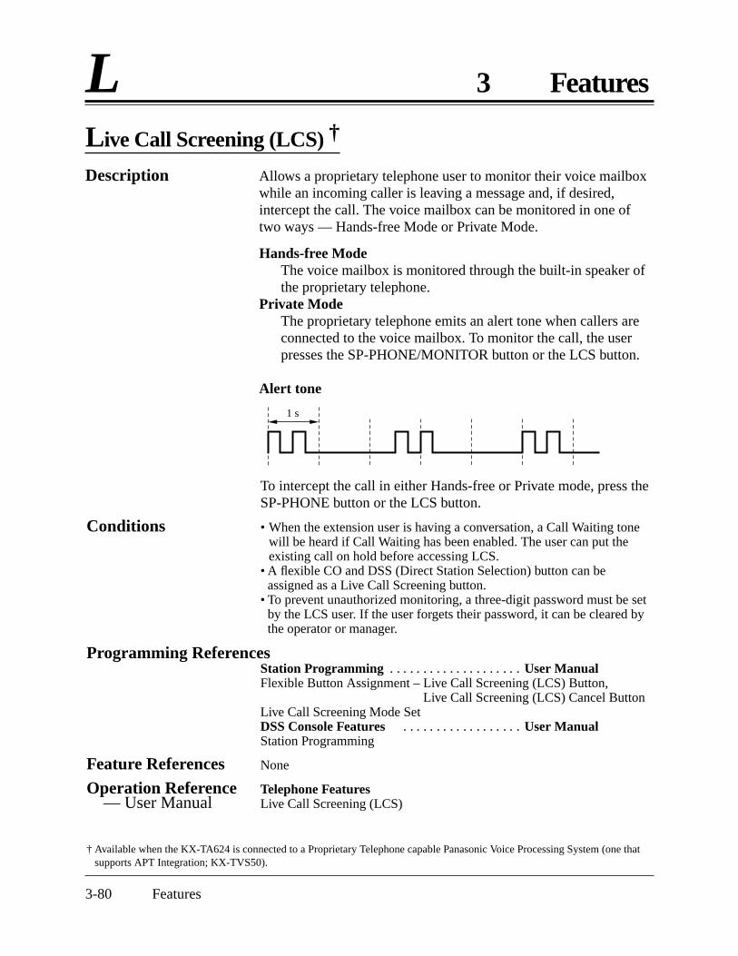
3-80 Features
L 3 Features
Live Call Screening (LCS) †
Description Allows a proprietary telephone user to monitor their voice mailboxwhile an incoming caller is leaving a message and, if desired,intercept the call. The voice mailbox can be monitored in one oftwo ways — Hands-free Mode or Private Mode.
Hands-free ModeThe voice mailbox is monitored through the built-in speaker ofthe proprietary telephone.
Private ModeThe proprietary telephone emits an alert tone when callers areconnected to the voice mailbox. To monitor the call, the userpresses the SP-PHONE/MONITOR button or the LCS button.
Alert tone
To intercept the call in either Hands-free or Private mode, press theSP-PHONE button or the LCS button.
Conditions • When the extension user is having a conversation, a Call Waiting tonewill be heard if Call Waiting has been enabled. The user can put theexisting call on hold before accessing LCS.
• A flexible CO and DSS (Direct Station Selection) button can beassigned as a Live Call Screening button.
• To prevent unauthorized monitoring, a three-digit password must be setby the LCS user. If the user forgets their password, it can be cleared bythe operator or manager.
Programming ReferencesStation Programming RRRRRRRRRR User ManualFlexible Button Assignment – Live Call Screening (LCS) Button,
Live Call Screening (LCS) Cancel ButtonLive Call Screening Mode SetDSS Console Features RRRRRRRRR User ManualStation Programming
Feature References None
Operation Reference Telephone Features— User Manual Live Call Screening (LCS)
† Available when the KX-TA624 is connected to a Proprietary Telephone capable Panasonic Voice Processing System (one thatsupports APT Integration; KX-TVS50).
1 s

Features 3-81
3 Features LLockout
Description If one party in a conversation goes on-hook, both parties will bedisconnected from the speech path automatically. This featureapplies to extension and outside calls. A reorder tone is sent to theoff-hook party before it is disconnected.
Condition • For a single line telephone, if nothing is dialed within a certain period oftime after the other party goes on-hook, a reorder tone will be sent to thesingle line telephone and then it will be disconnected from the speechpath.
Programming ReferencesNo programming required.
Feature References None
Operation Reference Telephone Features— User Manual Lockout

3-82 Features
L 3 Features
Log-In/Log-Out
Description Assigns an extension to join (log-in) or leave (log-out) a hunting orring group. Extensions in log-out status will not receive calls byStation Hunting or DISA but will receive other calls, unlike theDND feature.
Conditions • There should be at least one extension that is in log-in status.• The lighting patterns and status of the Log-In/Log-Out button are shown
below.
Programming ReferenceStation Programming RRRRRRRRRR User ManualFlexible Button Assignment – Log-In/Log-Out Button
Feature References Section 3, FeaturesDirect Inward System Access (DISA)Ring GroupStation Hunting
Operation Reference Telephone Features— User Manual Log-In/Log-Out
lighting pattern
Red On
Off
Log-In/Log-Out button Status
Log-Out
Log-In

Features 3-83
3 Features MManager Extension
Description The extension connected to Jack 01 becomes the system manager.This extension can perform system programming and the followingmanager services.
• Canceling the Call Log Lock and Electronic Station Lockout• Changing the Day/Night/Lunch mode manually• Recording and playing the outgoing message• Setting/Canceling/Confirming the Timed Reminder (Wake-up
Call) remotely• Setting/Clearing the Remote Station Lock Control• Setting the Date and Time• Setting the extension passwords
Conditions None
Programming ReferencesNo programming required.
Feature References None
Operation Reference Operator/Manager Service Features— User Manual

3-84 Features
M 3 Features
Message Waiting
Description The system supports the feature to notify the called party of amessage waiting. A proprietary telephone user with a MESSAGEbutton, knows there is a message if the LED on the MESSAGEbutton lights red. Pressing the lit MESSAGE button can call backthe called party or listen to the messages which are stored in themailbox of the Voice Processing System.
Conditions • For a proprietary telephone which does not have a MESSAGE button,such as the KX-T7055, this feature is not available.
• Canceling the message can be performed from the extension sending itor from the extension receiving it.
• Each extension can have a maximum of 8 simultaneous messages.• Messages are always left at the original extension. They cannot be sent
to a Call Forwarding or Station Hunting destination.
Programming ReferenceStation Programming RRRRRRRRRR User ManualFlexible Button Assignment – Return to Message Waiting (MESSAGE)
Button
Feature References Section 3, FeaturesCall ForwardingStation HuntingVoice Mail Integration for KX-TVS50Voice Mail Integration for KX-TVS75/KX-TVS100
Operation References Telephone Features—User Manual Message Waiting
Voice Mail Integration for KX-TVS50/KX-TVS75/KX-TVS100

Features 3-85
3 Features MMicrophone Mute
Description Allows a proprietary telephone user to turn off the microphone forprivacy.
Conditions • The user’s voice will only be muted during a hands-free conversation.• The user can hear the other party’s voice during Microphone Mute.
Programming ReferencesNo programming required.
Feature References None
Operation Reference Telephone Features — User Manual Microphone Mute (— for KX-T7020/KX-T7030/KX-T7130 only)
Mixed Station Capacities
Description This system supports a wide range of telephone sets, not onlyProprietary Telephones (PT) in the Advanced Hybrid System, butalso single line rotary telephones (10 pps/20 pps, using dial pulsesignals) and single line push-button dialing telephones (touch tone).The hybrid method used in this system allows any telephone to beconnected to an extension modular jack without an adaptor.
Condition • If a telephone is replaced with another one, the previous stored data(such as button features) remains.
Connection ReferenceSection 2, Installation2.3.4 Extension Connection
Programming ReferencesNo programming required.
Feature References None
Operation References Not applicable.

3-86 Features
M 3 Features
Module Expansion
Description The KX-TA624 starts with 3 outside (CO) line jacks and 8extension jacks.They can be expanded by installing expansion cards.
• A 3 CO Line and 8 EXT Expansion Card adds 3 outside (CO)line jacks and 8 extension jacks.
• An 8 Extension Expansion Card adds 8 extension jacks.The KX-TA624 can have one 3 CO Line and 8 EXT ExpansionCard and one 8 Extension Expansion Card. Thus, the KX-TA624can have 3 or 6 outside (CO) line jacks and 8, 16 or 24 extensionjacks.
Conditions None
Connection ReferenceStation 2, Installation2.4.4 Installing a 3 CO Line and 8 EXT Expansion Card (KX-TA62477)
and 8 Extension Expansion Card (KX-TA62470)
Programming ReferencesNo programming required.
Feature Reference Section 3, FeaturesParalleled Telephone
Operation References Not applicable.

Features 3-87
3 Features MMusic on Hold
Description While an external party is on hold, music is automatically activated.
Conditions • Operations such as Call Hold, Exclusive Call Hold or Call Transferactivate Music on Hold.
• A user-supplied external music source, such as a radio, must beconnected to the system. One external music source can be connected tothe system.
• A music source is used for Music on Hold and/or BGM. Systemprogramming may require enabling Music On Hold.
Connection ReferenceSection 2, Installation2.3.6 External Music Source Connection
Programming ReferenceSection 4, System Programming[111] Hold Music Selection
Feature Reference Section 3, FeaturesBackground Music (BGM)
Operation References Not applicable.

3-88 Features
O 3 Features
One-Touch Dialing
Description One-Touch Dialing offers a proprietary telephone (PT) user one-touch access to a desired party or system feature. This is activatedby storing an extension number, telephone number or a featurenumber (up to 24-digits) in an One-Touch Dialing button. Thenumber of buttons available depends on the type of PT. One-TouchDialing buttons can be programmed to flexible buttons.
Conditions • An account code can be stored into an One-Touch Dialing button.• Speed Dialing, One-Touch Dialing and manual dialing can be used at
the same time.• The user can store a number consisting of 25 digits or more by dividing
it and storing it in two One-Touch Dialing buttons. In this case, the lineaccess code should be stored in the first button.
Programming ReferencesStation Programming RRRRRRRRRR User Manual Flexible Button Assignment – One-Touch Dialing ButtonDSS Console Features RRRRRRRRRR User Manual Station Programming
Feature References None
Operation References Telephone Features — User Manual One-Touch Dialing
DSS Console FeaturesOne-Touch DialingOne-Touch Access for System Features

Features 3-89
3 Features OOne-Touch Transfer Using a DSS Button
Description This feature, if programmed, allows the Direct Station Selection(DSS) Console and the proprietary telephone user to hold anoutside call and quickly transfer it to an extension. While talking toan external party, pressing a DSS button on the console or aproprietary telephone provides automatic hold and transfer. There isno need to press the TRANSFER button. The extension startsringing immediately.
Condition • If “With Transfer” is assigned, the user transfers an outside call bypressing the TRANSFER button followed by the DSS button.
Programming ReferenceSection 4, System Programming[005] One-Touch Transfer Using a DSS Button
Feature Reference Section 3, FeaturesButton, Direct Station Selection (DSS)
Operation References Telephone Features — User Manual Call Transfer — to Extension
DSS Console FeaturesCall Transfer

3-90 Features
O 3 Features
Operator
Description The system supports one operator. Any extension can be designatedas an operator.The extension assigned as the operator has the ability to performthe following operations.
• Setting the Date and Time• Clearing the Call Log Lock and Electronic Station Lockout• Recording and playing the outgoing message• Setting/Clearing the Remote Station Lock Control• Changing the Day/Night/Lunch mode manually• Setting/Canceling/Confirming the Timed Reminder (Wake-up
Call) remotely
Conditions None
Programming ReferenceSection 4, System Programming[008] Operator Assignment
Feature References None
Operation Reference Operator/Manager Service Features— User Manual
Operator Call
Description Allows an extension user to call an extension operator by dialingthe feature number. One extension can be assigned as the operator.
Condition • If an operator is not assigned, this feature is not available and the userwill hear a reorder tone.
Programming ReferenceSection 4, System Programming[008] Operator Assignment
Feature References None
Operation Reference Telephone Features— User Manual Operator Call

Features 3-91
3 Features O
OGM1: “This is A company. For the sales division, press 1. For theservice division, press 2. To call the operator, press 0.”
OGM2: Same as OGM 1Required Settings: [502] “MODE1”
[414]-[416] “DISA1”
Case 2: Uses the OGM in the day, night and lunch modes – OGM for DISA.
Outgoing Message (OGM)
Description Allows the extension assigned as the operator or manager to recordan outgoing voice message. This message is played when a calleraccesses the DISA feature.After recording the message, the operator or manager can also playit back for confirmation.The following are some examples of OGM and flow chart.
Case 1: Receives 2 calls at a time – OGM for DISA.(Do not want customers to be kept waiting.)
DISA withOGM
To the designated destinationOutside Call
System
OGM 1
DISA withOGM
To the designated destinationOutside CallOGM 2
DISA withOGM
To the designated destinationOutside Call
System
OGM 1
(In the day mode)
DISA withOGM
The call is disconnected byassigning “Disconnect” forDISA 2 in program[510] “DISA No Dial Mode”.Outside Call
System
OGM 2
(In the night mode)
OGM1: “This is A company. For the sales division, press 1. For theservice division, press 2. To call the operator, press 0.”
OGM2: “We are sorry but our office is closed for the day.”Required Settings: [502] “MODE2”
[414]-[416] “DISA1” for OGM1, “DISA2” for OGM2

3-92 Features
O 3 Features
DISA withOGM
To the designated destinationOutside Call
System
OGM 1
DISA withOGM
To the designated destinationOutside CallOGM 2
Case 3: Uses a different OGM for outside (CO) lines – OGM for DISA.
OGM1: “This is A company. For the sales division, press 1. For theservice division, press 2. To call the operator, press 0.”
OGM2: “This is B company. To contact Mr. A, press 101. To contact Mr.B, press 102.”
Required Settings: [502] “MODE2”[414]-[416] “DISA1” for the A company outside (CO)
line(s).“DISA2” for the B company outside (CO)line(s).
(Outside line 1)
(Outside line 2)
DISA withOGM
To the designated destination
Outside Call
System
OGM 1
To the OperatorOGM 2
Case 4: Uses a different OGM when the line is busy – OGM for DISA.
The line is busy. (If the operatoris selected.)
OGM1: “This is A company. For the sales division, press 1. For theservice division, press 2. To call the operator, press 0.”
OGM2: “We are sorry. The line is currently busy. If you want to call theoperator, press 0.”
Required Settings: [502] “MODE2”[414]-[416] “DISA1”[506] “DISA2”
DISA withOGM

Features 3-93
3 Features OConditions • An optional OGM/FAX Detection Card is required to program the
OGM.• The maximum recording time for the OGM is 30 seconds.• Up to two outgoing messages are available.
Connection ReferenceSection 2, Installation2.4.2 Caller ID and OGM/FAX Detection Card Installation
Programming References[414]–[416] Outside (CO) Line Mode — Day/Night/Lunch[502] OGM Mode Selection[506] DISA Busy Mode
Feature Reference Section 3, FeaturesDirect Inward System Access (DISA)
Operation Reference Operator/Manager Service Features— User Manual Outgoing Message (OGM)

3-94 Features
O 3 Features
Outside (CO) Line Connection Assignment
Description This allows a user to specify which outside (CO) lines areconnected to their system. This prevents the user from calling a linewhich is not connected. When the user uses Automatic LineAccess, an idle line is selected from the ones connected.
Conditions • If the user tries to make a call with a disconnected line, a reorder tonewill sound to indicate that the line is out of use.
• This is effective for all outgoing calls including DISA.
Programming ReferenceSection 4, System Programming[400] Outside (CO) Line Connection Assignment
Feature References None
Operation References Not applicable.
Outside (CO) Line Connection Assignment – Outgoing
Description Allows a user to assign an outside (CO) line used for outgoingcalls. This feature is useful in preventing unauthorized toll calls.
Conditions • When an extension user tries to make an outside call on a disallowedoutside (CO) line, a reorder tone is sent to indicate that the user cannotuse that outside (CO) line.
• Day, Night and Lunch Service are programmed individually. (TimeService)
Programming ReferencesSection 4, System Programming[405]–[407] Flexible Outward Dialing Assignment — Day/Night/Lunch
Feature References None
Operation References Not applicable.

Features 3-95
3 Features OOutside (CO) Line Group
Description Outside (CO) lines can be grouped into up to six outside (CO) linegroups. This allows extensions to call outside parties withoutdesignating a specific outside (CO) line, since an outside (CO) lineis automatically selected from the designated outside (CO) linegroup. All outside (CO) lines belong to an outside (CO) line group.
Condition • Each outside (CO) line can only belong to one outside (CO) line group.
Programming ReferenceSection 4, System Programming[404] Outside (CO) Line Group Assignment
Feature References None
Operation References Not applicable.
3-96 Features
P 3 Features
PAGING FEATURES – SUMMARY
Description Paging allows a user to make a voice announcement to many peopleat the same time. Their message is announced over the built-inspeakers of proprietary telephones and/or an external speaker(external pager). The paged person can answer the page from anearby telephone. Making and answering a page is possible fromeither a proprietary or single line telephone. The user can page witha call on hold in order to transfer the call (Paging and Transfer).It is also possible to deny a page.The paging features are classified as follows.
Paging – All Paging – ExternalPaging – Group
Paging – All
Description Allows the user to make a voice announcement from the speakersof proprietary telephones and external paging device (externalpager).
Conditions • A confirmation tone is sent to the extensions, when a page is sent oranswered.
• A confirmation tone is sent to the external pager, before the voiceannouncement. The tone can be disabled.
• A ringing or busy extension cannot receive a page.
Connection ReferenceSection 2, Installation2.3.5 External Pager (Paging Equipment) Connection
Programming ReferenceSection 4, System Programming[106] External Paging Access Tone
Feature References None
Operation References Telephone Features— User Manual Paging — All
Paging and TransferPaging — ANSWERPaging — DENY

Features 3-97
3 Features PPaging – External
Description Allows the user to make a voice announcement using an externalpaging device (external pager). One pager can be connected. Anytelephone user can answer the Paging – External.
Conditions • An external pager must be connected beforehand.• A confirmation tone is sent to the extensions and external pager, when a
page is sent. The tone to the external pager can be disabled.
Connection ReferenceSection 2, Installation2.3.5 External Pager (Paging Equipment) Connection
Programming ReferenceSection 4, System Programming[106] External Paging Access Tone
Feature References None
Operation References Telephone Features— User Manual Paging — External Paging and Transfer
Paging — ANSWER Paging — DENY
Paging – Group
Description Allows the user to select an extension group and make a voiceannouncement. All the proprietary telephones in the group willreceive the page. If a member of the paged group answers the page,they can talk to the person through the connected line.
Conditions • To select all groups, page all of the extensions.• A confirmation tone is sent when a page is sent or answered.
Programming ReferencesNo programming required.
Feature Reference Section 3, FeaturesExtension Group
Operation References Telephone Features— User Manual Paging — External Paging and Transfer
Paging — ANSWER Paging — DENY

3-98 Features
P 3 Features
Paralleled Telephone
Description Any analog proprietary telephone can be connected in parallel withsingle line devices, such as a single line telephone, facsimile anddata terminal.When a parallel connection is made, an extension user can makeand answer a call using either telephone.
Conditions • A proprietary telephone (PT) can perform normal operations even ifprogram [610] is assigned to “Disable”.
• If one telephone goes off-hook while the other telephone is having acall, a three-party call will be established. If one user goes on-hook, theother user will continue with the call.
• When receiving a call, both the PT and the single line telephone willring except when the PT is in the Hands-free Answerback mode.
• When the single line telephone is operating, the display and LEDindicator on the paired PT will work as if the PT is in operation.
• The extension user cannot originate a call from the single line telephoneif the PT is:
— playing BGM,— in programming mode, or— receiving a page announcement over the built-in speaker.
• The Call Waiting tone can only be heard by a PT.• The paired single line telephone will not ring in the following cases.
— When the PT user sets the Hands-free Answerback feature.— When the voice alerting mode is set on the PT.
• The paired single line telephone cannot use the following features.— Call Splitting— Conference— External Feature Access— Door Opener while talking to the doorphone— Pickup Dialing
• The paired single line telephone user should not enter “49” or “ ”before the account code. They cannot enter the account code during orafter a call.
Connection ReferenceSection 2, Installation2.3.7 Paralleled Telephone Connection (for a Proprietary Telephone and
a Single Line Telephone)
Programming ReferenceSection 4, System Programming[610] Paralleled Telephone Connection
Feature References None
Operation Reference Telephone Features— User Manual Paralleled Telephone Connection

Features 3-99
3 Features PPause Insertion, Automatic
Description This feature is used to insert a pre-assigned pause between theoutside (CO) line access number, the host PBX code, carrier codeor code assigned in program [311] and the dialed number.
Conditions • This feature requires programming the host PBX codes, carrier codesand automatic pause insertion codes as well as the pause durationbeforehand.
• This feature works for Speed Dialing, One-Touch Dialing, Last NumberRedial, Saved Number Redial, Pickup Dialing, Call Forwarding – toOutside (CO) Line as well as for normal calls.
• Pressing the PAUSE button in a dialing number inserts a pause for a pre-assigned time.
Programming ReferencesSection 4, System Programming[300] Carrier Code Assignment[311] Automatic Pause Insertion Codes[403] Host PBX Access Codes[417] Pause Time
Feature References Section 3, FeaturesHost PBX AccessToll Restriction
Operation References Not applicable.

3-100 Features
P 3 Features
Personal Speed Dialing
Description Allows an extension user to store frequently dialed numbers inorder to place a call quickly. This is done by dialing the featurenumber and a speed dial number, from 0 to 9. Up to 10 numberswith a maximum of 24 digits per number can be stored in eachtelephone.
Conditions • For PT users, it is impossible to use this feature if One-Touch Dialingbuttons are assigned to PF buttons. If the user assigns, a personal speeddialing number, the number stored in the One-Touch Dialing button willbe overwritten. PF Buttons F1 through F10 correspond to speed dialingnumbers as follows.
F1 — 0 F6 — 5F2 — 1 F7 — 6F3 — 2 F8 — 7F4 — 3 F9 — 8F5 — 4 F10 — 9
• If a single line telephone user wants to check the stored number,exchange the telephone with a proprietary telephone. PF buttonsF1 through F10 correspond to speed dialing numbers 0 through 9. Pressthe desired PF button to check the number.
• A rotary telephone user cannot use this feature.
Programming ReferencesNo programming required.
Feature Reference Section 3, FeaturesOne-Touch Dialing
Operation Reference Telephone Features— User Manual Personal Speed Dialing
Features 3-101
3 Features PPickup Dialing
Description Allows a single line telephone user to make an outgoing call bygoing off-hook, if the user has stored the telephone numberbeforehand. This feature is also known as Hot Line.
Conditions • A proprietary telephone and rotary telephone cannot program thisfeature.
• The user uses a feature number to activate or deactivate pickup dialing. • If the feature is activated and the user goes off-hook, a dial tone will be
generated for the delay time and then dialing will start. During the delaytime, the user can dial another party overriding the Pickup Dialingfeature.
Programming ReferenceSection 4, System Programming[203] Pickup Dial Delay Time
Feature References None
Operation Reference Telephone Features— User Manual Pickup Dialing (Hot Line) (— Single Line Telephone only)

3-102 Features
P 3 Features
Power Failure Transfer
Description If a power failure occurs, or the system is off-line, specificextension telephones are automatically connected to specificoutside (CO) lines. This provides an outside (CO) line call betweenthe following extensions and outside (CO) lines.
Outside (CO) line 1 is connected to extension jack number 01.Outside (CO) line 4 is connected to extension jack number 09.
A single line telephone can work during a power failure. Connect asingle line telephone to the above extension jack.
Conditions • All other conversations, except the above combinations, aredisconnected during a power failure.
• Only an outside (CO) line can have a conversation. All other features donot work.
Connection ReferencesSection 2, Installation2.3.3 Outside (CO) Line Connection 2.3.4 Extension Connection2.5 Auxiliary Connection for Power Failure Transfer
Programming ReferencesNo programming required.
Feature References None
Operation Reference Telephone Features— User Manual Power Failure Transfer

Features 3-103
3 Features PPulse to Tone Conversion
Description This feature allows the extension user to change from pulse dialingto tone (DTMF) dialing so that the user can access special services,such as computer-accessed long distance calls or voice mailservices.
Conditions • This feature only works for outside (CO) lines which have set the PulseDialing mode or Call Blocking mode.
• The user can select the dial mode for each outside (CO) line using theDial Type Selection feature.
• Changing from tone to pulse is not possible.
Programming ReferencesSection 4, System Programming[119] Redialing After Pulse to Tone Conversion[401] Dial Mode
Feature Reference Section 3, FeaturesDial Type Selection
Operation Reference Telephone Features— User Manual Pulse to Tone Conversion

3-104 Features
R 3 Features
Redial, Last Number
Description Every telephone in the system automatically saves the lasttelephone number dialed to an outside (CO) line and allows theextension user to dial the same number again.
Conditions • With a proprietary telephone, the REDIAL button is used to carry outLast Number Redial. With a single line telephone, the feature number isused.
Programming ReferencesNo programming required.
Operation Reference Telephone Features— User Manual Redial, Last Number
Redial, Saved Number
Description Allows a proprietary telephone user to save a telephone number andredial the number afterwards. The user can store it during aconversation with an outside (CO) line. The saved number can beredialed until another number is stored.
Conditions • As the SAVE button is not provided on a PT, except for the KX-T7130,a flexible button can be assigned as the SAVE button.
Programming ReferenceStation Programming RRRRRRRRRR User ManualFlexible Button Assignment – SAVE Button
Feature References Section 3, FeaturesButton, Flexible
Operation Reference Telephone Features— User Manual Redial, Saved Number
Features 3-105
3 Features RRemote Station Lock Control
Description The operator and manager are given the privilege of controlingElectronic Station Lockout and Call Log Lock at any station.
Conditions • Remote Station Lock Control has higher priority over Electronic StationLockout and Call Log Lock. If Electronic Station Lockout or Call LogLock has already been set by the extension user and Remote StationLock is set by the operator or manager, canceling the lock is onlypossible by the operator or manager.
• Extension passwords must be assigned to the operator and managerextensions beforehand.
• The Electronic Station Lockout — CANCEL ALL feature can cancelthis feature.
• When the same extension number Station Lock button is assigned on theoperator and manager DSS Consoles, one can set and the other cancancel the feature, and vice versa.
• A toll restriction COS number can be assigned for this feature. Certaintypes of outgoing outside calls are permitted depending on the assignedtoll restriction COS number.
Programming ReferencesSection 4, System Programming[108] Flash Mode for a Station Locked Extension[312] Toll Restriction — Station Lock Boundary ClassDSS Console Features RRRRRRRRRR User ManualStation Programming — Station Lock Button Assignment (Operator and
Manager only)
Feature References Section 3, FeaturesCall Log, IncomingElectronic Station LockoutToll Restriction — Station Lock Boundary Class
Operation References Operator/Manager Service Features — User Manual Electronic Station Lockout — CANCEL ALL
Extension Password Set (Manager only)Remote Station Lock Control

3-106 Features
R 3 Features
Ringing, Delayed
Description A telephone is originally set to ring immediately. This feature canbe changed to delayed ringing or no ringing (disable) on an outside(CO) line number basis.
Conditions • This feature does not apply to DISA or DIL calls. If the destination is aring group, the delayed ringing feature will work.
• The extension can answer an incoming call during no ring or the delaytime by pressing the flashing button.
Programming ReferencesSection 4, System Programming[408]–[410] Flexible Ringing Assignment — Day/Night/Lunch[411]–[413] Delayed Ringing Assignment — Day/Night/Lunch
Feature References Section 3, FeaturesDirect In Lines (DIL)Direct Inward System Access (DISA)Ring Group
Operation References Not applicable.
Ring Group
Description All extensions in a ring group ring simultaneously if the ring groupis assigned as the destination of AA (DISA built-in auto attendant)number. A ring group is a specific extension group.
Conditions None
Programming ReferencesSection 4, System Programming[501] DISA Built-in Auto Attendant[600] Extension Group Assignment
Feature Reference Section 3, FeaturesDirect Inward System Access (DISA)
Operation References Not applicable.

Features 3-107
3 Features RRinging, Discriminating
Description Allows the extension user to identify an incoming call by its ringingpattern. (See section 5.1, “Tone/Ring Tone”.)
Conditions • If multiple incoming calls arrive at an on-hook extensionsimultaneously, priority is generally on a “first-come, first-serve” basis.For proprietary telephones (PT), when the Prime Line Preference –Incoming feature has been set, this line has priority.
• A PT user can select a desired ringing pattern for each outside (CO) line,intercom, and the doorphone ringing tone for each doorphone.
Programming ReferencesSection 4, System Programming[115] Extension Ringing Pattern Selection[423] Outside (CO) Line Ringing Pattern Selection[706] Doorphone Ringing/Tone Pattern Selection
Feature References Section 3, FeaturesRinging Pattern Selection for Intercom Calls and Outside (CO) LinesRinging Tone Selection for Doorphones
Operation References Not applicable.
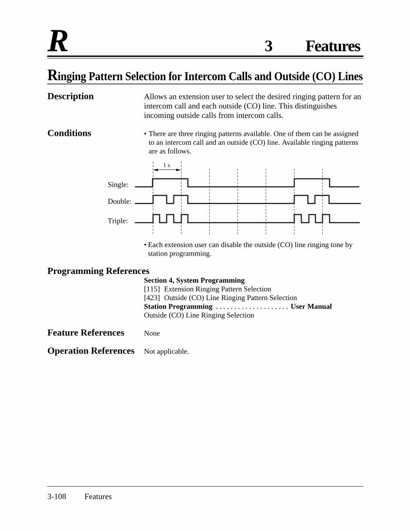
3-108 Features
R 3 Features
Ringing Pattern Selection for Intercom Calls and Outside (CO) Lines
Description Allows an extension user to select the desired ringing pattern for anintercom call and each outside (CO) line. This distinguishesincoming outside calls from intercom calls.
Conditions • There are three ringing patterns available. One of them can be assignedto an intercom call and an outside (CO) line. Available ringing patternsare as follows.
1 s
Single:
Double:
Triple:
• Each extension user can disable the outside (CO) line ringing tone bystation programming.
Programming ReferencesSection 4, System Programming [115] Extension Ringing Pattern Selection[423] Outside (CO) Line Ringing Pattern SelectionStation Programming RRRRRRRRRR User ManualOutside (CO) Line Ringing Selection
Feature References None
Operation References Not applicable.

Features 3-109
3 Features RRinging Tone Selection for Doorphones
Description Allows an extension user to select the desired ringing or tonepattern for each doorphone. This distinguishes incoming doorphonecalls.A PT user will hear a tone with the assigned pattern and a singleline telephone user will hear a ringing tone with the assignedpattern.
Condition • There are four types of ringing tones as follows.
1 s
Single:
Double:
Triple:
S-Double:
Programming ReferenceSection 4, System Programming [706] Doorphone Ringing/Tone Pattern Selection
Feature References None
Operation References Not applicable.
3-110 Features
R 3 Features
Room Monitor
Description Allows a user to monitor another room or the front door through aproprietary telephone or doorphone without them knowing.
Conditions • The extensions which can be monitored must be programmed.• An access tone will not be sent to the monitored proprietary telephone
when monitoring starts.• If a doorphone is used as the room monitor, a doorphone access tone
will be heard when monitoring starts. The tone can be disabled.• This feature is not available for the KX-T7050 and KX-T7055.• A single line telephone with a MUTE button can be used for monitoring.
Programming ReferencesSection 4, System Programming[612] Room Monitor Assignment[707] Doorphone Access Tone Selection
Feature Reference Section 3, FeaturesDoorphone Call
Operation Reference Telephone Features— User Manual Room Monitor

Features 3-111
3 Features SSecret Dialing
Description Allows an extension user to conceal all or part of a registeredtelephone number that normally appears on the display. The usercan hide System Speed Dialing or One-Touch Dialing numbersassigned to flexible buttons on proprietary telephones and DSSConsoles. When a display telephone user calls a Secret Dialingnumber, all or part of the number will not appear on the display.
Conditions • When storing a number, press the INTERCOM button at the beginningand the end of the number to be concealed.
• The user can conceal one or more parts of a telephone number.• Printing out the concealed parts on a SMDR can be assigned by system
programming.
Programming ReferencesSection 4, System Programming[001] System Speed Dialing Entry[803] Secret Speed Dialing/One-Touch Dialing PrintingStation Programming RRRRRRRRRR User ManualFlexible Button Assignment – One-Touch Dialing Button
Feature References Section 3, FeaturesOne-Touch DialingStation Message Detail Recording (SMDR)System Speed Dialing
Operation Reference Telephone Features— User Manual Secret Dialing

3-112 Features
S 3 Features
Station Feature Clear
Description Allows an extension user to cancel the features set on the user’sown telephone. The following features will be canceled by thisfeature.
Absent Message Capability – The message set on the telephoneAutomatic Callback Busy (Camp-On)Background Music that has been turned onCall ForwardingCall Log, Incoming – Over-stored modeCall Pickup DenyCall Waiting disabledData Line SecurityDo Not Disturb (DND)Executive Busy Override DenyLog-In/Log-OutMessage Waiting – All the messages that have been left by
other extension usersPickup Dialing – The stored telephone numberPaging – DenyRoom MonitorTimed ReminderVoice Mail Integration
Conditions None
Programming ReferencesNo programming required.
Feature References None
Operation Reference Telephone Features— User Manual Station Feature Clear

Features 3-113
3 Features SStation Hunting
Description If a called extension is busy, Station Hunting redirects the incomingcall to an idle extension in the extension group. Idle extensions areautomatically searched according to programming. Two huntingtypes are available as follows.
Circular hunting: The extensions are searched one time innumerical order until an idle one is found. If all extensions arebusy, a busy tone will be heard. Terminate hunting: The extensions are searched from thedestination jack until the call reaches the highest jack number inthe group. If all higher number jacks are busy, the search willend and a busy tone will be heard.
One hunting type can be selected for each extension group.To leave the hunting group temporarily, use the Log-Out function.To rejoin, use the Log-In feature.
Condition • If the called extension has set Do Not Disturb, Call Forwarding orLog-Out, Station Hunting will skip the extension. However, StationHunting will not skip the extension which receives the call first, even ifit has set Do Not Disturb or Call Forwarding.
Programming ReferencesSection 4, System Programming[100] Hunting Group Set[101] Station Hunting Type[600] Extension Group Assignment
Feature References Section 3, FeaturesCall ForwardingDo Not DisturbExtension GroupLog-In/Log-Out
Operation References Not applicable.

3-114 Features
S 3 Features
Station Message Detail Recording (SMDR)
Description Station Message Detail Recording (SMDR) automatically prints outdetailed call information of outside calls. A printer connected to theSerial Interface (RS-232C) port can be used to print incoming andoutgoing outside calls, as well as print a hard copy of systemprogramming. To print out the record of system programming itemsthat have been assigned, use program [804] “System Data Dump”.To print the call records, use program [802] “Incoming/OutgoingCall Selection for Printing”, which allows a user to print out thefollowing records.
• A record of all outgoing outside calls or outgoing toll calls• A record of all incoming outside calls
Example of the SMDR printout format:Explanation(1) Date: shows the date of the call as month/day/year.(2) Time: shows the time the call was started as Hour: Minute/AM
or PM. “*” indicates a transferred call.(3) Ext.: shows the extension number, etc. that engaged in the call.
“C-xx” indicates an outside-to-outside (CO-to-CO) callvia DISA. The outside (CO) line which receives anincoming call is shown as xx.
(4) CO: shows the outside (CO) line number used for the call.
An example of a printed call record:
Date Time Ext. CO Dial number Duration Code
12/31/98 12:52PM 103 05 12345678901234567890123456789012 00:00'16 . . . .
12/31/98 12:53PM 103 02 < incoming >2013570846 00:01'43 . . . .
12/31/98 *12:54PM 101 02 < incoming >1234567890123456 00:07'48 . . . .
12/31/98 1:04PM 103 06 092. . . 1438 00:00'06 4536
12/31/98 1:04PM 102 05 < DISA incoming >2013570846 00:00'09 . . . . 0
12/31/98 1:05PM 103 01 < DISA incoming > 00:00'08 . . . . 0
12/31/98 1:06PM 103 01 092123456789 00:00'08 . . . .
12/31/98 1:06PM C-05 02 0921234567 00:00'17 . . . . 2
12/31/98 1:07PM 103 01 0921234567 00:11'00 . . 13
12/31/98 2:15PM 103 01 0921234567 00:11'00 . 101
12/31/98 2:26PM 103 01 F/0927654321 00:03'00 . . . .
12/31/98 2:27PM 116 05 9=0924567123 00:13'55 . . . .• • • • • • •• • • • • • •• • • • • • •
(1) (2) (3) (4) (5) (6) (7)

Features 3-115
3 Features S(5) Dial number
Outgoing call: shows the called party’s telephone number(maximum 32 digits). Valid digits are 0 through 9, , # or P(if the PAUSE button was pressed).Received call: shows <incoming>. If a Caller ID is assignedto the other party, it will show <incoming> and the number.An incoming call via DISA is shown as <DISA incoming>.An incoming call via DIL is shown as <DIL incoming>.
(6) Duration: shows the duration of the call inhours/minutes/seconds.
(7) Code: shows the account code appended to the call, accountcode index number, the extension number whichoverrides toll restriction or the DISA security codestatus. Code “0” indicates a DISA incoming callwithout a DISA security code. Codes “1 to 4”indicate a DISA incoming call with DISA securitycode 01 to 04 respectively. DISA security codes arenever printed out by SMDR.
Conditions • This system can store information of up to 64 calls.• This data is not deleted when the user resets the system.• If FLASH is manually sent during a conversation to make another call
without hanging up, etc., the call record will be printed out and a newrecord is started. “F/” will be printed at the top of the dial number on thenew record.
• When a host PBX code is entered, “=” will be printed between the codeand dialed number.
Connection ReferenceSection 2, Installation2.3.9 Printer and PC Connection
Programming ReferencesSection 4, System Programming[000] Date and Time Setting[204] Call Duration Count Start Time[800] SMDR RS-232C Communication Parameters[801] SMDR Parameter[802] Incoming/Outgoing Call Selection for Printing[803] Secret Speed Dialing/One-Touch Dialing Printing[804] System Data Dump[805] SMDR Account Code Selection[906] Caller ID SMDR Format
Feature References None
Operation References Not applicable.

3-116 Features
S 3 Features
Station Programming
Description Allows a proprietary telephone (PT) user to customize theirextension according to their needs. The following programmingitems are available.For a PT (KX-T7130; KX-T7020; KX-T7030; KX-T7050;KX-T7055)
Call Waiting Tone Type AssignmentFlexible Button Assignment Intercom Alert AssignmentOutside (CO) Line Ringing SelectionPreferred Line Assignment – Incoming/OutgoingStation Programming Data Default Set
For a display PT (KX-T7130; KX-T7030) only,Self-Extension Number Confirmation
For an operator and manager’s extension PT only,Date and Time SettingElectronic Station Lockout — CANCEL ALLOutgoing Message Recording/Playback
For the manager’s extension PT only,Extension Password
Detailed information and programming instructions are described inthe User Manual, Station Programming and Operator/ManagerService Features.
Condition • During station programming, a PT is regarded as busy.
Programming ReferencesStation Programming RRRRRRRRRR User ManualOperator/Manager Service Features RRR User ManualDate and Time SettingElectronic Station Lockout — CANCEL ALLExtension Password Set (Manager only)Outgoing Message (OGM)
Feature References None
Operation References Not applicable.

Features 3-117
3 Features SStation Programming Data Default Set
Description Allows a proprietary telephone user to return all the following itemsprogrammed on the telephone to the default settings.
Programming Items DefaultCall Waiting Tone Type Assignment Tone 1Intercom Alert Assignment Tone CallOutside (CO) Line Ringing Selection Ring-all outside (CO)
linesPreferred Line Assignment – Incoming Ringing LinePreferred Line Assignment – Outgoing No Line
Station programming is used to set or cancel these items atindividual telephones.
Condition • This feature also cancels the Hands-free Answerback feature andpressing the AUTO ANSWER/MUTE button in the Room Monitorfeature.
Programming ReferenceStation Programming RRRRRRRRRR User ManualStation Programming Data Default Set
Feature References Section 3, FeaturesHands-free AnswerbackRoom MonitorStation Programming
Operation References Not applicable.

3-118 Features
S 3 Features
System Data Default Set
Description This system can re-initialize the system-programmed data. If all theprogrammed data is cleared, the system will restart using thedefault settings.
Condition • The default setting for each programming item is listed in Section 5.2,“Default Values”.
Programming ReferenceSection 4, System Programming[999] System Data Clear
Feature References None
Operation Reference Section 2, Installation2.9 System Data Clear
System Programming with a Proprietary Telephone
Description This system can be programmed with a proprietary telephone (PT).Proprietary telephones available for system programming are:KX-T7130, and KX-T7030 (Display Proprietary Telephones).An extension connected to JACK 01 is allowed to perform systemprogramming.For more information and programming instructions, refer toSection 4, “System Programming”.
Conditions • During system programming, the system operates normally.• During system programming, the extension is regarded as busy.• To access system administration, a valid password must be entered. The
password is factory-programmed and can be changed.
Programming ReferenceSection 4, System Programming[002] System Password
Feature References None
Operation References Not applicable.
Features 3-119
3 Features SSystem Speed Dialing
Description This feature supports 100 abbreviated dial numbers that areavailable to all users. A system speed dial number is dialed out bypressing the AUTO DIAL/STORE button for a proprietarytelephone and pressing “ ” for a single line telephone, and a2-digit code (00 through 99). Up to one hundred telephone numbers(32-digit) can be stored per system.
Conditions • Toll Restriction for System Speed Dialing can be assigned by systemprogramming.
• Rotary single line telephones cannot use the feature.[For proprietary telephone users only]• Speed Dialing, One-Touch Dialing and manual dialing can be used
together.
Programming ReferencesSection 4, System Programming[001] System Speed Dialing Entry[301] Toll Restriction – System Speed Dialing Boundary Class
Feature Reference Section 3, FeaturesToll Restriction for System Speed Dialing
Operation Reference Telephone Features— User Manual System Speed Dialing

3-120 Features
T 3 Features
Time (Day/Night/Lunch) Service
Description The system supports the day, night and lunch operation modes. Thesystem operation for originating and receiving calls can be differentfor the day, night and lunch modes. The system operation forrestricting toll calls can be programmed to prevent unauthorized tollcalls in each mode.Changing the Day/Night/Lunch ModesThe day/night/lunch modes can be changed either automatically at apre-assigned time or manually by the operator or manager at anydesired time.
Automatic Time Service: If a user selects the automaticchanging mode, the system will change the day/night/lunchmodes at the programmed time each day. The starting time ofthe day/night/lunch modes can be set for each day of the week.Manual Time Service: If a user selects the manual changingmode, the operator or manager can change the day/night/lunchmodes by dialing the feature number or pressing the day, nightor lunch button.
Conditions • The following programming items may be assigned differently for theday mode, night mode and lunch mode.[405]–[407] Flexible Outward Dialing Assignment — Day/Night/Lunch[408]–[410] Flexible Ringing Assignment — Day/Night/Lunch[411]–[413] Delayed Ringing Assignment — Day/Night/Lunch[414]–[416] Outside (CO) Line Mode — Day/Night/Lunch[601]–[603] TRS – Class of Service (COS) Assignment
— Day/Night/Lunch[700]–[702] Doorphone Ringing Assignment — Day/Night/Lunch[703]–[705] Door Opener Assignment — Day/Night/Lunch
• The operator or manager can change the day, night or lunch mode evenif the automatic changing mode is selected.
Programming ReferencesSection 4, System Programming[006] Time (Day/Night/Lunch) Service Changing Mode[007] Time (Day/Night/Lunch) Service Start TimeDSS Console Features RRRRRRRRRR User ManualStation Programming — Day Button Assignment (Operator and Manager
only)Night Button Assignment (Operator andManager only)Lunch Button Assignment (Operator andManager only)

Features 3-121
3 Features TFeature References None
Operation References Telephone Features— User Manual Time (Day/Night/Lunch) Service
Operator/Manager Service FeaturesTime (Day/Night/Lunch) Service Setting
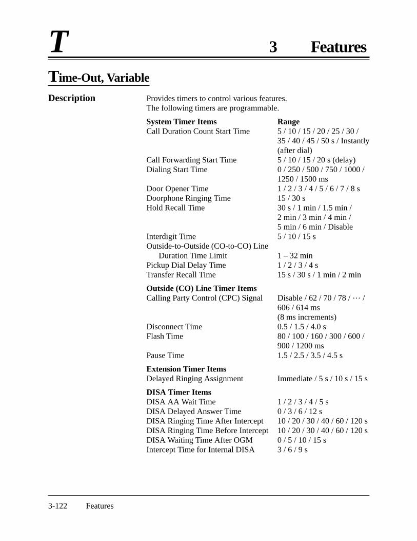
3-122 Features
T 3 Features
Time-Out, Variable
Description Provides timers to control various features.The following timers are programmable.
System Timer Items RangeCall Duration Count Start Time 5 / 10 / 15 / 20 / 25 / 30 /
35 / 40 / 45 / 50 s / Instantly(after dial)
Call Forwarding Start Time 5 / 10 / 15 / 20 s (delay)Dialing Start Time 0 / 250 / 500 / 750 / 1000 /
1250 / 1500 msDoor Opener Time 1 / 2 / 3 / 4 / 5 / 6 / 7 / 8 sDoorphone Ringing Time 15 / 30 sHold Recall Time 30 s / 1 min / 1.5 min /
2 min / 3 min / 4 min /5 min / 6 min / Disable
Interdigit Time 5 / 10 / 15 sOutside-to-Outside (CO-to-CO) Line
Duration Time Limit 1 – 32 minPickup Dial Delay Time 1 / 2 / 3 / 4 sTransfer Recall Time 15 s / 30 s / 1 min / 2 min
Outside (CO) Line Timer ItemsCalling Party Control (CPC) Signal Disable / 62 / 70 / 78 / … /
606 / 614 ms (8 ms increments)
Disconnect Time 0.5 / 1.5 / 4.0 sFlash Time 80 / 100 / 160 / 300 / 600 /
900 / 1200 msPause Time 1.5 / 2.5 / 3.5 / 4.5 s
Extension Timer ItemsDelayed Ringing Assignment Immediate / 5 s / 10 s / 15 s
DISA Timer ItemsDISA AA Wait Time 1 / 2 / 3 / 4 / 5 sDISA Delayed Answer Time 0 / 3 / 6 / 12 sDISA Ringing Time After Intercept 10 / 20 / 30 / 40 / 60 / 120 sDISA Ringing Time Before Intercept 10 / 20 / 30 / 40 / 60 / 120 sDISA Waiting Time After OGM 0 / 5 / 10 / 15 sIntercept Time for Internal DISA 3 / 6 / 9 s

Features 3-123
3 Features TProgramming References
Section 4, System Programming[200] Hold Recall Time[201] Transfer Recall Time[202] Call Forwarding Start Time[203] Pickup Dial Delay Time[204] Call Duration Count Start Time[205] Outside-to-Outside (CO-to-CO) Line Duration Time Limit[206] Dialing Start Time[208] Interdigit Time[411]–[413] Delayed Ringing Assignment — Day/Night/Lunch[417] Pause Time[418] Flash Time[420] Calling Party Control (CPC) Signal[422] Disconnect Time[504] DISA Delayed Answer Time[505] DISA Waiting Time after OGM[508] DISA Ringing Time before Intercept[509] DISA Ringing Time after Intercept[515] Intercept Time For Internal DISA[517] DISA AA Wait Time[708] Doorphone Ringing Time[709] Door Opener Time
Feature References None
Operation References Not applicable.

3-124 Features
T 3 Features
Timed Reminder
Description Each telephone can generate an alarm tone at a preset time as awake-up tone or reminder. The alarm can be set to occur daily orjust once.
Conditions • Be sure that the system clock is working.• Setting a new time clears the preset time.• The alarm sounds for 30 seconds. To stop it, lift the handset or, with a
proprietary telephone, press any button.• There is no limit for the number of the extensions who can set Timed
Reminder at the same time.
Programming ReferencesNo programming required.
Feature Reference Section 3, FeaturesTimed Reminder, Remote (Wake-Up Call)
Operation Reference Telephone Features— User Manual Timed Reminder
Timed Reminder, Remote (Wake-Up Call)
Description Allows the operator and manager to remotely set, cancel andconfirm a wake-up call for an extension.
Conditions • When either an operator/manager or extension sets a new time, the pre-set time is cleared.
• There is no limit for the number of the extensions that can set TimedReminder at the same time.
• Each extension user can cancel this feature.
Programming ReferencesNo programming required.
Feature Reference Section 3, FeaturesTimed Reminder
Operation Reference Operator/Manager Service Features— User Manual Timed Reminder, Remote (Wake-Up Call)
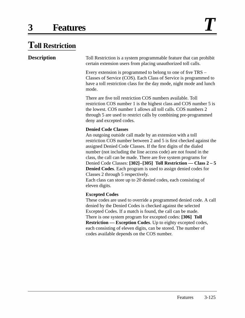
Features 3-125
3 Features TToll Restriction
Description Toll Restriction is a system programmable feature that can prohibitcertain extension users from placing unauthorized toll calls.
Every extension is programmed to belong to one of five TRS –Classes of Service (COS). Each Class of Service is programmed tohave a toll restriction class for the day mode, night mode and lunchmode.
There are five toll restriction COS numbers available. Tollrestriction COS number 1 is the highest class and COS number 5 isthe lowest. COS number 1 allows all toll calls. COS numbers 2through 5 are used to restrict calls by combining pre-programmeddeny and excepted codes.
Denied Code ClassesAn outgoing outside call made by an extension with a tollrestriction COS number between 2 and 5 is first checked against theassigned Denied Code Classes. If the first digits of the dialednumber (not including the line access code) are not found in theclass, the call can be made. There are five system programs forDenied Code Classes: [302]–[305] Toll Restriction — Class 2 – 5Denied Codes. Each program is used to assign denied codes forClasses 2 through 5 respectively.Each class can store up to 20 denied codes, each consisting ofeleven digits.
Excepted CodesThese codes are used to override a programmed denied code. A calldenied by the Denied Codes is checked against the selectedExcepted Codes. If a match is found, the call can be made.There is one system program for excepted codes: [306] TollRestriction — Exception Codes. Up to eighty excepted codes,each consisting of eleven digits, can be stored. The number ofcodes available depends on the COS number.

3-126 Features
T 3 Features
Applicable Denied Code Classes and Excepted Codes depend onthe assigned toll restriction COS number of an extension as follows.
[Explanation]COS 1: allows all calls.COS 2: denies the 20 codes stored in Denied Code Class 2 assigned in
program [302], except all codes stored in Code numbers01 through 80 assigned in program [306].
COS 3: denies the 40 codes stored in Denied Code Classes 2 and 3assigned in programs [302] and [303], except the 60 codes storedin Code numbers 01 through 60 assigned in program [306].
COS 4: denies the 60 codes stored in Denied Code Classes 2 through 4assigned in programs [302] through [304], except the 40 codesstored in Code numbers 01 through 40 assigned in program [306].
COS 5: denies the 80 codes stored in Denied Code Classes 2 through 5assigned in programs [302] through [305], except the 20 codesstored in Code numbers 01 through 20 assigned in program [306].
Example of Toll Restriction programmingHere is an example to explain the procedure for Toll Restrictionprogramming.
1. Determining the applicationDetermine the dialing numbers that should be denied for COSnumbers 2 through 5. (1 is fixed and does not requireprogramming.)
COS Number
1
2
3
4
5
Denied Codes
None
Codes for Class 2
Codes for Classes 2 and 3
Codes for Classes 2 to 4
Codes for Classes 2 to 5
Excepted Codes
None
All codes from Code number 01 to 80
15 codes from Code number 01 to 60
10 codes from Code number 01 to 40
5 codes from Code number 01 to 20
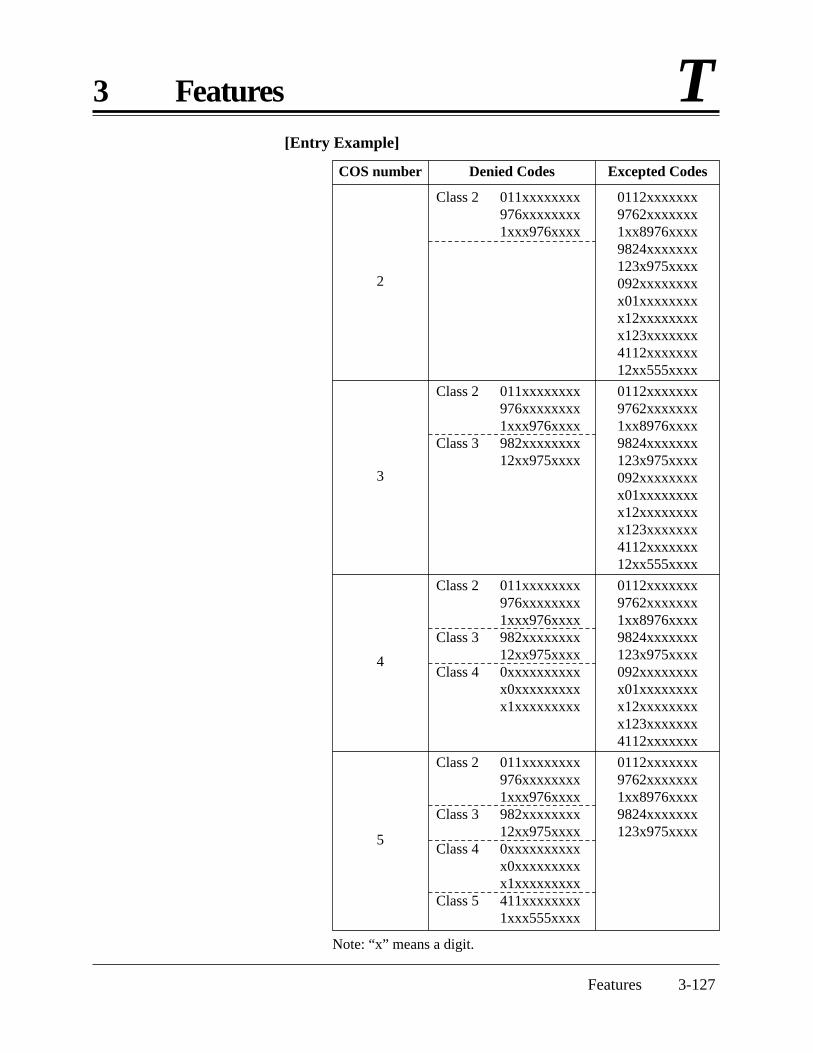
Features 3-127
3 Features T[Entry Example]
Note: “x” means a digit.
COS number
2
3
4
5
Denied Codes
Class 2 011xxxxxxxx976xxxxxxxx1xxx976xxxx
Class 2 011xxxxxxxx976xxxxxxxx1xxx976xxxx
Class 3 982xxxxxxxx12xx975xxxx
Class 2 011xxxxxxxx976xxxxxxxx1xxx976xxxx
Class 3 982xxxxxxxx12xx975xxxx
Class 4 0xxxxxxxxxxx0xxxxxxxxxx1xxxxxxxxx
Class 2 011xxxxxxxx976xxxxxxxx1xxx976xxxx
Class 3 982xxxxxxxx12xx975xxxx
Class 4 0xxxxxxxxxxx0xxxxxxxxxx1xxxxxxxxx
Class 5 411xxxxxxxx1xxx555xxxx
0112xxxxxxx9762xxxxxxx1xx8976xxxx9824xxxxxxx123x975xxxx092xxxxxxxxx01xxxxxxxxx12xxxxxxxxx123xxxxxxx4112xxxxxxx12xx555xxxx
0112xxxxxxx9762xxxxxxx1xx8976xxxx9824xxxxxxx123x975xxxx092xxxxxxxxx01xxxxxxxxx12xxxxxxxxx123xxxxxxx4112xxxxxxx12xx555xxxx
0112xxxxxxx9762xxxxxxx1xx8976xxxx9824xxxxxxx123x975xxxx092xxxxxxxxx01xxxxxxxxx12xxxxxxxxx123xxxxxxx4112xxxxxxx
0112xxxxxxx9762xxxxxxx1xx8976xxxx9824xxxxxxx123x975xxxx
Excepted Codes

3-128 Features
T 3 Features
[Explanation]If your extension is jack 03;a) You cannot make a call whose toll call number is “011”, because the
number “011” is one of the Denied Codes for Class 2.b) However, you can make a call whose toll call number is “0112”. The
number, whose first 3 digits are “011”, is one of the Denied Codes forClass 2, but the number “0112” is one of the Excepted Codes. TheExcepted Codes override the Denied Codes.
If your extension is jack 08;a) You cannot make a call whose toll call number is “123”, because the
number “1xxx976xxx” is one of the Denied Codes for Class 2.b) However, you can make a call whose toll call number is
“1234975680”. The number, whose first 3 digits are “123”, is one ofthe Denied Codes for Class 2, but the number “123x975xxx” is one ofthe Excepted Codes. The Excepted Codes override the Denied Codes.
2. Programming[601]–[603] TRS – Class of Service (COS) Assignment
— Day/Night/LunchAssign a Class of Service (COS) to each extension.[Example]
Jack
01
02
03..
08..
24
1
1
2..
5..
5
1
5
4..
5..
1
1
1
5..
5..
5
COS (Day) COS (Night) COS (Lunch)

Features 3-129
3 Features TThe user makes a toll call.
The call is denied. A reorder toneis sent to the user.
The call is allowed.
Is the dialed number found in theapplicable Excepted Codes?
Is the dialed number found in theapplicable Denied Codes?
What is the extension – COSnumber?
Is the call made by System SpeedDialing? *1
Is the COS number higherthan the System SpeedDialing Boundary Class? *2
Yes
No or Equal
Yes
Yes
No
COS 1
COS 2, 3, 4, 5
NoYes
Flow Chart of Toll Restriction
*1 System Speed Dial numbers are assigned in program [001] “System Speed Dialing Entry”.*2 The System Speed Dialing Boundary Class is assigned in program [301] “Toll Restriction – System
Speed Dialing Boundary Class”.
No

3-130 Features
T 3 Features
Conditions • Toll restriction checks are applied to the following features.(1) Account Code Entry(2) Dial Access, Automatic(3) Dial Access, Outside (CO) Line Group(4) Line Access, Individual (5) Carrier Code Entry (6) System Speed Dialing
• Emergency numbers, the Police or Fire Department, should be stored inprogram [309] “Emergency Dial Number Set” so that they are exceptedfrom toll restriction.
• If a stored Host PBX access code or a stored carrier code is found in thedialed number, the subsequent telephone numbers will be checked fortoll restriction.
• It is programmable whether the “ ” or “#” the user dials is to bechecked or not on the Toll Restriction code. This is useful to preventunauthorized calls which could be possible through certain CentralOffice exchange systems.
Programming ReferencesSection 4, System Programming[125] Toll Restriction Check for and #[208] Interdigit Time[211] No Dial Disconnection[300] Carrier Code Assignment[301] Toll Restriction — System Speed Dialing Boundary Class[302]–[305] Toll Restriction — Class 2 – 5 Denied Codes[306] Toll Restriction — Exception Codes[601]–[603] TRS – Class of Service (COS) Assignment
— Day/Night/Lunch
Feature References Section 3, FeaturesToll Restriction for Special Carrier AccessToll Restriction for System Speed DialingToll Restriction Override by Account CodesToll Restriction — Station Lock Boundary Class
Operation References Not applicable.

Features 3-131
3 Features TToll Restriction for Special Carrier Access
Description If the system has access to multiple telephone companies, access toa specific company requires a carrier code before the telephonenumber. Toll Restriction for these calls is activated by storing thecarrier codes (maximum 20). If a stored carrier code is found in thedialed number, a toll restriction check starts with the subsequenttelephone numbers.
Conditions None
Programming ReferenceSection 4, System Programming[300] Carrier Code Assignment
Feature Reference Section 3, FeaturesToll Restriction
Operation References Not applicable.

3-132 Features
T 3 Features
Toll Restriction for System Speed Dialing
Description Toll Restriction for System Speed Dialing is assigned separatelyfrom the extensions. There are five boundary classes available.
N = No restriction C = Checked
[Explanation]The System Speed Dialing Boundary Class works with the COS numberassigned to each extension.(1) Boundary Class 5: all extension users can make system speed dialing
calls without checking any COS number.(2) Boundary Class 4: extensions with COS number 5 are checked. When
the users make system speed dialing calls, toll restriction COS number5 is applied to the numbers.
(3) Boundary Class 3: extensions with COS numbers 4 and 5 are checked.When the users make system speed dialing calls, toll restriction COSnumbers 4 and 5 are applied to the numbers.
(4) Boundary Class 2: extensions with COS numbers 3 through 5 arechecked. When the users make system speed dialing calls, tollrestriction COS numbers 3 through 5 are applied to the numbers.
(5) Boundary Class 1: extensions with COS numbers 2 through 5 arechecked. When the users make system speed dialing calls, tollrestriction COS numbers 2 through 5 are applied to the numbers.
Conditions None
Programming ReferenceSection 4, System Programming[301] Toll Restriction — System Speed Dialing Boundary Class
Feature References Section 3, FeaturesSystem Speed Dialing Walking COSToll Restriction
Operation Reference Telephone Features— User Manual Toll Restriction Override – Toll Restriction for System Speed Dialing
Extension COSnumber
1
2
3
4
5
N
C
C
C
C
N
N
C
C
C
N
N
N
C
C
N
N
N
N
C
N
N
N
N
N
System Speed Dialing Boundary Class1 2 3 4 5

Features 3-133
3 Features T
Verify - AllOption/Forced
Toll Restriction Override by Account Codes
Description Allows an extension user to override toll restriction temporarily tomake a toll call from a toll-restricted extension. The user can carryout this feature by entering a pre-assigned account code beforedialing the telephone number. The user can make a toll call with theCOS number 2.
Conditions • The account code “Verify - Toll” mode at an extension permits users tooverride their toll restrictions.
• This feature can be used on extensions assigned to toll restriction COSnumbers 3 through 5. The COS numbers 1 and 2 will not be changed.
• If the user does not enter an account code or enters an invalid one, aregular toll restriction check is done.
• When a user makes a call using this feature, it will appear on the SMDRprintout with either the entered 4-digit account code or the 2-digit indexof the entered account code. This selection is set in program [805]“SMDR Account Code Selection”.
• Users can also override toll restriction of another extension by using theWalking COS feature.
TRS Override by Account Codes is attempted.
What is the account code mode?
The Toll Restriction COS numberremains the same as the extensionbeing used.
The call is made with the COS number 2.
The call is not allowed.A reorder tone is returnedto the user.
Does the entered code match astored account code?
No
Yes
Yes No
Verify - Toll
Flow Chart of TRS Override
Does the entered code match astored account code?
No
Is the COS number 1?Yes

3-134 Features
T 3 Features
Programming ReferencesSection 4, System Programming[605] Account Code Entry ModeOperator/Manager Service Features RRRR User ManualExtension Password Set (Manager only)
Feature References Section 3, FeaturesAccount Code EntryStation Message Detail Recording (SMDR)Toll RestrictionWalking COS
Operation Reference Telephone Features— User Manual Toll Restriction Override — Toll Restriction Override by Account Codes
Features 3-135
3 Features TToll Restriction — Station Lock Boundary Class
Description Allows assigning a toll restriction class when the Electronic StationLockout or Remote Station Lock feature is set.An extension user usually cannot make an outside call at a lockedextension, however if a toll restriction class is assigned in program[312], the user can make an outside call at the locked extension.
Condition • The higher toll restriction COS number will take precedence.For example, if toll restriction COS number 4 is assigned to anextension and the station lock boundary class is 3, the extension user isallowed to make a call with toll restriction COS 4.
Programming ReferenceSection 4, System Programming[312] Toll Restriction — Station Lock Boundary Class
Feature References Section 3, FeaturesElectronic Station LockoutRemote Station Lock ControlToll Restriction
Operation References Not applicable.

3-136 Features
V 3 Features
Outside Call
System
OperatorC.FWD
Transfer
DIL, DISA
Extension
Outside Call
System
ExtensionC.FWD
DIL, DISA
Intercom Call
Voice Mail Integration for KX-TVS50
Description When a Panasonic Voice Processing System (KX-TVS50) isconnected to the system, they communicate in a tightly integratedfashion (APT Integration). For example, the system sends the VoiceProcessing System (VPS) data which contains extension numberconfiguration information and then the VPS automatically createsmailboxes with this data (Auto Configuration — Quick setup).
The system informs a VPS of the state of a call (busy, answered,ringing, disconnected, etc.) through APT Integration. The Systemalso informs a VPS through APT Integration of the destination of acall transferred to the VPS by the Call Forwarding or DISAIntercept Routing — No Answer feature. This APT Integration isestablished automatically when a VPS is connected to the system.
System Explanation1. Voice Mail Service
1.1 Call Forwarding to VMIf an extension user sets Call Forwarding (C. FWD) whosedestination is the VPS, an incoming call will be forwarded to theVPS. The system will send the VPS the extension mailboxnumber at that time. Therefore, the calling party can leavehis/her message in the mailbox of the desired extension withouthaving to know the mailbox number.
Port 1 Port 2
VM Hunting Chain
KX-TVS50
Port 1 Port 2
VM Hunting Chain
KX-TVS50

Features 3-137
3 Features V
Outside Call
System
Extension Port 1
Port 2
Intercept
DISA
KX-TVS50
1.2 DISA Intercept to VMIf the VPS is set as the Intercept destination of an outside (CO)line, an outside call will be forwarded to the VPS. The systemwill send the VPS the extension mailbox number at that time.Therefore, the calling party can leave their message in themailbox of the desired extension without knowing the mailboxnumber. Delayed Ringing must be assigned to voice mailextensions.
1.3 Special Features for a Proprietary Telephone throughAPT Integration
The following features are available only with a proprietarytelephone in APT Integration.
Live Call Screening (LCS)Voice Mail Transfer
With these features, a proprietary telephone user can monitorincoming messages being recorded into his/her mailbox oreasily transfer an outside calls to a desired extension mailbox.
1.4 Listening to a Recorded Message If the VPS receives a message or records a conversation, theVPS can turn on the MESSAGE button indicator on thecorresponding proprietary telephone to notify the user. TheVPS notifies the extension user that there is a message waitingin their mailbox. When the MESSAGE button indicator is lit,pressing the button allows the extension user to play back thestored message. A single line telephone user hears dial tone 3when going off-hook if there are messages in their mailbox.They can call the voice mail extension to listen to theirmessages. In this case, they must listen to all of the messages.Once they access voice mail, dial tone 3 will be eliminated andnot be heard next time they go off-hook. Therefore, they willnot know even if there are messages left.

3-138 Features
V 3 Features
Outside Call
System
Extension AA 1 AA 2
AA Hunting Chain
KX-TVS50Transfer
DIL
2. Automated Attendant (AA) Service2.1 AA to ExtensionAA receives and answers outside calls and offers services suchas transferring to an extension or mailbox using DTMFsignaling, which is sent from the calling party.
Outside Call
System
Extension
AA 1
AA 2
Normal
Immediately
10 s delay
15 s delay
KX-TVS50
2.2 Extension BackupIf the voice mail extensions are assigned to ring with otherextensions, for example the operator extension, for the sameoutside (CO) line, voice mail extensions can be used as backupfor the operator when the operator cannot answer an incomingoutside call. Delayed Ringing must be assigned to voice mailextensions.

Features 3-139
3 Features VConditions • A maximum of two VPSs can be connected to the system.
• A maximum of four extension jacks (07, 08, 15 and 16) of the systemcan be connected to VPSs with four-conductor wire. Extension jacknumber 07, or jack numbers 07 and 08 can be the voice mail APT portsfor VPS1 in program [130]. Extension jack number 15, or jack numbers15 and 16 can be for VPS2 in program [131].
• When “Port 7 & 8” is selected in program [130], extension jacknumbers 07 and 08 will be in extension group 7 automatically.Likewise, when “Port 15 & 16” is selected in program [131], extensionjack numbers 15 and 16 will be in extension group 8 automatically. Alsothe Station Hunting type is set as “Circular”, and the VM Hunting Chainand AA Hunting Chain are enabled automatically in each of these twoextension groups.
• The lowest jack number (07 or 15) of each extension group must beconnected to the Port 1 of a VPS. The VPS data is transmitted to theVPS via the Port 1.
• One connection between the system and a VPS, for example extensionjack number 07 of the system and Port 1 of the VPS, creates one VoiceMail extension and can only answer one call. Therefore, if one VPS isconnected to the system, maximum of two calls can be answeredsimultaneously.
• A VPS can be assigned as the destination for the following features.Call Forwarding – All CallsCall Forwarding – Busy/No AnswerDISA Intercept Routing – No Answer
For these features, the caller does not need to know the mailbox numberof the called extension because the code is automatically transmitted tothe VPS (Follow On ID feature). If a DISA call is transferred to theVPS by Intercept Routing from a ring group, the system will transmitthe mailbox number of the lowest jack number of the receivingextensions.
• The mailbox number is the same as its extension number.• Data Line Security is set automatically on the Voice Mail extension.
Extensiongroup 8
KX-TA624
15
16
Port 1
Port 2
KX-TVS50 (VPS2)
7
8
Port 1
Port 2
KX-TVS50 (VPS1)
Extensiongroup 7

3-140 Features
V 3 Features
Connection ReferenceSection 2, Installation2.3.4 Extension Connection
Programming ReferencesSection 4, System Programming[009] Extension Number Assignment[100] Hunting Group Set[101] Station Hunting Type[130] Voice Mail 1 APT Port for KX-TVS50[131] Voice Mail 2 APT Port for KX-TVS50[408]–[410] Flexible Ringing Assignment — Day/Night/Lunch[411]–[413] Delayed Ringing Assignment — Day/Night/Lunch[414]–[416] Outside (CO) Line Mode — Day/Night/Lunch[507] DISA Intercept Mode[600] Extension Group AssignmentStation Programming RRRRRRRRRR User ManualFlexible Button Assignment – Return to Message Waiting (MESSAGE)
Button
Feature References Section 3, FeaturesCall Forwarding – All Calls Intercept RoutingCall Forwarding – Busy/No Answer Live Call Screening (LCS)Direct Inward System Access (DISA) Station Hunting
Operation Reference Telephone Features— User Manual Live Call Screening (LCS)
Voice Mail Integration for KX-TVS50/KX-TVS75/KX-TVS100Voice Mail Transfer
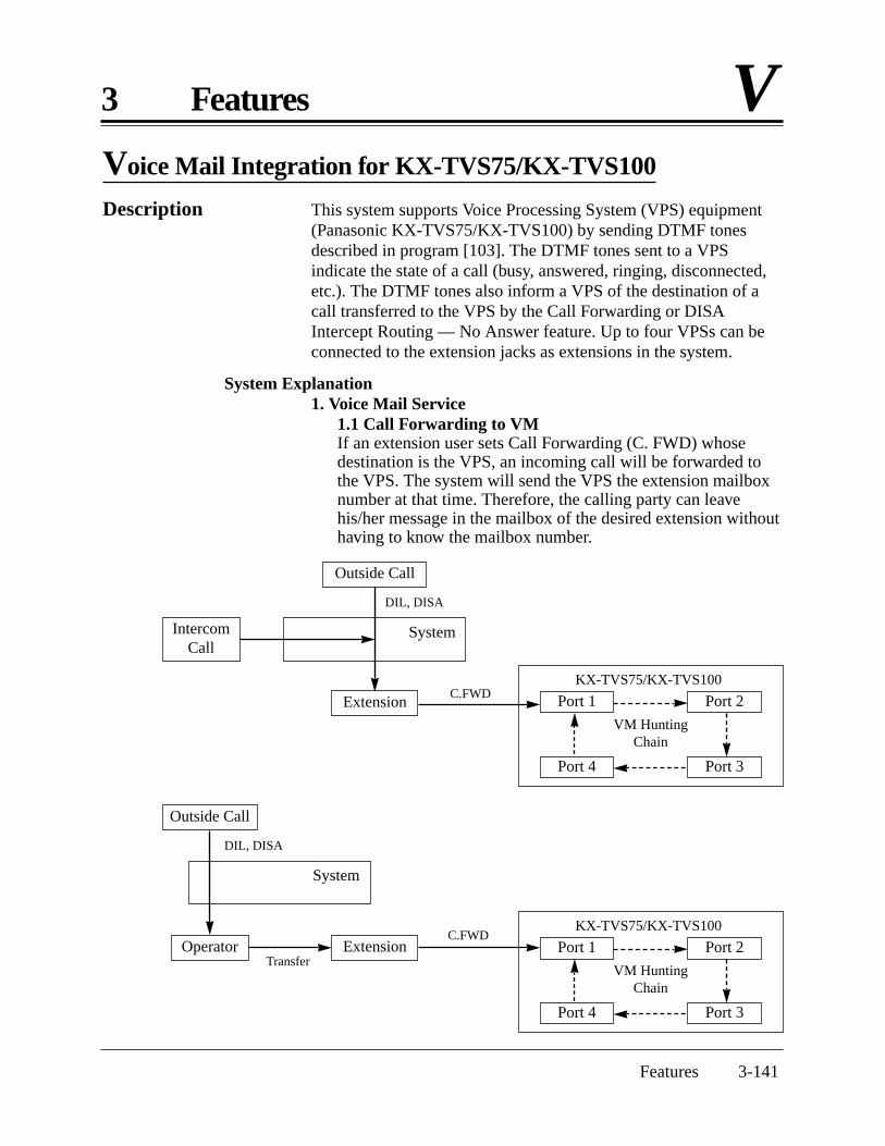
Features 3-141
3 Features V
Outside Call
System
Extension Port 1
Port 4
Port 2
Port 3
VM HuntingChain
KX-TVS75/KX-TVS100
Port 1
Port 4
Port 2
Port 3
VM HuntingChain
KX-TVS75/KX-TVS100
C.FWD
DIL, DISA
IntercomCall
Voice Mail Integration for KX-TVS75/KX-TVS100
Description This system supports Voice Processing System (VPS) equipment(Panasonic KX-TVS75/KX-TVS100) by sending DTMF tonesdescribed in program [103]. The DTMF tones sent to a VPSindicate the state of a call (busy, answered, ringing, disconnected,etc.). The DTMF tones also inform a VPS of the destination of acall transferred to the VPS by the Call Forwarding or DISAIntercept Routing — No Answer feature. Up to four VPSs can beconnected to the extension jacks as extensions in the system.
System Explanation1. Voice Mail Service
1.1 Call Forwarding to VMIf an extension user sets Call Forwarding (C. FWD) whosedestination is the VPS, an incoming call will be forwarded tothe VPS. The system will send the VPS the extension mailboxnumber at that time. Therefore, the calling party can leavehis/her message in the mailbox of the desired extension withouthaving to know the mailbox number.
Outside Call
System
OperatorC.FWD
Transfer
DIL, DISA
Extension
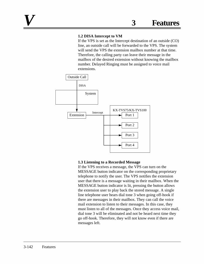
3-142 Features
V 3 Features
Outside Call
System
Extension Port 1
Port 2
Port 3
Port 4
Intercept
DISA
KX-TVS75/KX-TVS100
1.2 DISA Intercept to VMIf the VPS is set as the Intercept destination of an outside (CO)line, an outside call will be forwarded to the VPS. The systemwill send the VPS the extension mailbox number at that time.Therefore, the calling party can leave their message in themailbox of the desired extension without knowing the mailboxnumber. Delayed Ringing must be assigned to voice mailextensions.
1.3 Listening to a Recorded Message If the VPS receives a message, the VPS can turn on theMESSAGE button indicator on the corresponding proprietarytelephone to notify the user. The VPS notifies the extensionuser that there is a message waiting in their mailbox. When theMESSAGE button indicator is lit, pressing the button allowsthe extension user to play back the stored message. A singleline telephone user hears dial tone 3 when going off-hook ifthere are messages in their mailbox. They can call the voicemail extension to listen to their messages. In this case, theymust listen to all of the messages. Once they access voice mail,dial tone 3 will be eliminated and not be heard next time theygo off-hook. Therefore, they will not know even if there aremessages left.
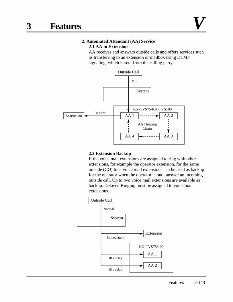
Features 3-143
3 Features V
Outside Call
System
Extension AA 1 AA 2
AA 4 AA 3
AA HuntingChain
KX-TVS75/KX-TVS100Transfer
DIL
2. Automated Attendant (AA) Service2.1 AA to ExtensionAA receives and answers outside calls and offers services suchas transferring to an extension or mailbox using DTMFsignaling, which is sent from the calling party.
Outside Call
System
Extension
AA 1
AA 2
Normal
Immediately
10 s delay
15 s delay
KX-TVS75/100
2.2 Extension BackupIf the voice mail extensions are assigned to ring with otherextensions, for example the operator extension, for the sameoutside (CO) line, voice mail extensions can be used as backupfor the operator when the operator cannot answer an incomingoutside call. Up to two voice mail extensions are available asbackup. Delayed Ringing must be assigned to voice mailextensions.

3-144 Features
V 3 Features
Conditions • A VPS can be assigned as the destination for the following features.Call Forwarding – All CallsCall Forwarding – Busy/No AnswerDISA Intercept Routing – No Answer
For these features, the caller does not need to know the mailbox numberof the called extension because the code is automatically transmitted tothe VPS (Follow On ID feature). If a DISA call is transferred to the VPSby Intercept Routing from a ring group, the system will transmit themailbox number of the lowest jack number of the receiving extensions.
• The mailbox number is the same as its extension number.• The Voice Mail extension should set Data Line Security to achieve
proper recording.• If KX-TA624 cannot be selected with the PBX type setup menu of the
KX-TVS75/KX-TVS100, select “KX-T1232”. Follow the steps for aKX-T1232.
• Enable the VM Hunting Chain and AA Hunting Chain as follows.1) Assign all Voice Mail extensions to one extension group in program
[600].2) Assign “Enable” to the group in program [100].3) Assign the hunting type to the group in program [101].
Connection ReferenceSection 2, Installation2.3.4 Extension Connection
Programming ReferencesSection 4, System Programming[009] Extension Number Assignment[100] Hunting Group Set[101] Station Hunting Type[102] Voice Mail Port for KX-TVS75/KX-TVS100[103] DTMF Integration for KX-TVS75/KX-TVS100[408]–[410] Flexible Ringing Assignment — Day/Night/Lunch[411]–[413] Delayed Ringing Assignment — Day/Night/Lunch[414]–[416] Outside (CO) Line Mode — Day/Night/Lunch[507] DISA Intercept Mode[600] Extension Group AssignmentStation Programming RRRRRRRRRR User ManualFlexible Button Assignment – Return to Message Waiting (MESSAGE)
Button
Feature References Section 3, FeaturesCall Forwarding – All Calls Intercept RoutingCall Forwarding – Busy/No Answer Station HuntingDirect Inward System Access (DISA)
Operation Reference Telephone Features— User Manual Voice Mail Integration for KX-TVS50/KX-TVS75/KX-TVS100

Features 3-145
3 Features VVolume Control – Handset Receiver/Headset/Ringer/Speaker
Description Allows a proprietary telephone user to change the following asdesired.
Handset receiver volume Headset volumeRinger volumeSpeaker volume
Condition • The procedure is as follows.Slide the following levers located on the left side of the telephone.
Volume Control (MIN – MAX)Handset (Headset) Volume Selector (NORMAL – HIGH)Ringer Volume Selector (OFF / LOW / HIGH)
Programming ReferencesNo programming required.
Feature References None
Operation Reference Configuration— User Manual Initial Settings — Volume Control – Handset Receiver/Headset/
Ringer/Speaker

3-146 Features
W 3 Features
Walking COS
Description Allows a user who is not at their own telephone to override the tollrestriction COS number of another extension. At the otherextension, the user dials their extension password. For the durationof the call, the COS of the extension is changed to the COS of theirown extension.
Conditions • When a user makes a call using this feature, the user’s extension numberwill be displayed on the SMDR, not the extension where the user madethe call.
• If the extension overriding toll restriction is assigned to the AccountCode — Forced or Verify - All mode, the user must enter the accountcode before the line access code.
Programming ReferenceOperator/Manager Service Features RRR User ManualExtension Password Set (Manager only)
Feature Reference Section 3, FeaturesToll Restriction Override by Account Codes
Operation Reference Telephone Features— User Manual Walking COS

Section 4System Programming
This section provides step-by-step programming instructions for a proprietary telephone.
4.1 General Programming Instructions
4-2 System Programming
Default SettingThis system has factory default settings. If any of the programmingneeds to be changed, the necessary information will be found inSection 3, “Features”. This makes the system very simple to installand customize as required by the customer. Any required changescan be written in the “Programming Tables”.
Required Telephone SetOne of the following telephone sets is required for systemprogramming.• Proprietary Telephone (PT): KX-T7130, KX-T7030
Extensions Used for ProgrammingOnly the manager extension can perform system programming. Theextension user connected to Jack number 01 is the managerextension.

4.1.1 Using Proprietary Telephones
System Programming 4-3
Using the OverlayA programming overlay is packed with the telephone at the factory.This overlay should be used at all times during programming. Thefeatures of the telephone keys change during programming asfollows. (The original features are in parentheses.)
During Normal Operation During Programming(PAUSE) PAUSE
(SP-PHONE) NEXT(REDIAL) PREV (PREVIOUS)
(AUTO ANSWER/MUTE) SELECT(FLASH) FLASH
(TRANSFER) CLEAR(FWD/DND)
(CONF) , – (KX-T7030) / (KX-T7130)(INTERCOM ) SECRET
(AUTO DIAL/STORE) STORE(HOLD) END(SAVE) , – (KX-T7130 only)
Location of Controls with the OverlayThe pictures below show the features of the buttons of theKX-T7030 and KX-T7130 during programming.
KX-T7030 KX-T7130
SECRET
SELECT
CLEAR
PAUSE
STORE
NEXTENDFLASHPREV
, –
AUTO
SECRET
SELECT
CLEAR
PAUSE
STORE
NEXTENDFLASHPREV
, –
AUTO

4.1.1 Using Proprietary Telephones
4-4 System Programming
Viewing the DisplayThe display gives the user helpful information, such as the nextstep, previous entries, etc.The KX-T7130 and the KX-T7030 both utilize one information linefor programming.The display capacity is 16 digits. If the entry is longer than16 digits, the user can shift the display by pressing the or button.
Before entering the programming modeBefore entering the programming mode, confirm that:
• The telephone is on-hook.• No calls are on hold at your telephone.
Entering the programming mode
1. Set the MEMORY switch on the telephone to“PROGRAM”.The display shows: PITS-PGM NO? →
2. Dial #.The display shows: Password :
3. Enter the system password (default 1234).The display shows the initial system programmingmessage: SYS-PGM NO? →
Note • The entered system password is not shown on the display. The systempassword can be changed by system programming. Refer to Section 4.2[002] “System Password”.
• During the programming mode, the extension is treated as a busyextension.

4.1.2 Programming Methods
System Programming 4-5
Advancing to the next stageWhen “SYS-PGM NO? →” is displayed, the user can go to thedesired program by entering the 3-digit program address.
Storing your dataPress STORE to store the data.
• The STORE indicator lights red and a confirmation tone isheard.
* Confirmation tone (one beep)After pressing STORE, a beep will be heard. This informs the userthat storing is completed.
* Confirmation tone (two beeps)This informs the user that the same parameter has already beenstored.
* Alarm tone (three beeps)If this alarm is heard, the user’s entry is not valid.
Making another selection within the same program address• To make the next selection, press NEXT.• To make the previous selection, press PREV.• To make a specific selection, press SELECT and then enter the
number.
Confirming the entriesThe user may review the stored programming without making anychanges.
Going to another program addressPress END and the initial system programming message will bedisplayed.The display shows: PITS-PGM NO? →Then enter a program address.You can go to the higher number program address by pressing the
button and the lower number by pressing the button whilethe program title is displayed.Display example: Date/Time Set
program title
Returning to the operation modeSet the MEMORY switch to “SET”.
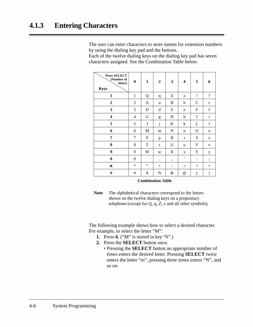
Press SELECT(Number of
times)
4.1.3 Entering Characters
4-6 System Programming
The user can enter characters to store names for extension numbersby using the dialing key pad and the buttons.Each of the twelve dialing keys on the dialing key pad has sevencharacters assigned. See the Combination Table below.
Keys
1
2
3
4
5
6
7
8
9
0
#
0
1
2
3
4
5
6
7
8
9
0
*
#
1
Q
A
D
G
J
M
P
T
W
”
$
2
q
a
d
g
j
m
p
t
w
.
+
%
3
Z
B
E
H
K
N
R
U
X
,
–
&
4
z
b
e
h
k
n
r
u
x
’
=
@
5
!
C
F
I
L
O
S
V
Y
:
<
(
6
?
c
f
i
l
o
s
v
y
;
>
)
Combination Table
Note The alphabetical characters correspond to the lettersshown on the twelve dialing keys on a proprietarytelephone (except for Q, q, Z, z and all other symbols).
The following example shows how to select a desired character.For example, to select the letter “M”:
1. Press 6. (“M” is stored in key “6”.)2. Press the SELECT button once.
• Pressing the SELECT button an appropriate number oftimes enters the desired letter. Pressing SELECT twiceenters the letter “m”, pressing three times enters “N”, andso on.

4.1.3 Entering Characters
System Programming 4-7
Example of entering characters: to enter “Mike”:The display shows:
1. Enter 6. 62. Press SELECT. M3. Enter 4. M44. Press SELECT six times. Mi5. Enter 5. Mi56. Press SELECT four times. Mik7. Enter 3. Mik38. Press SELECT four times. Mike
Note • To erase all the letters, press CLEAR.• To erase the last letter, press .

4.1.4 Programming Example
4-8 System Programming
Sample of Description Explanation
(1) Program address: This address is printed at the top ofevery page to quickly find the desired program.
(2) Mode title.
(3) Program title.
(4) Provides a more detailed description of the program.
(5) Shows the user the assignable choices.
(6) Shows the user the factory default setting.
(7) Shows the user programming procedures step by step.• During programming, use the overlay.• Before starting to program, enter the programming
mode. (See “Entering the programming mode” onpage 4-4.)
(8) Enter the program address.
(9) The display shows the program title.
(10) Press NEXT shown on the overlay.
(11) The display asks the user to enter a speed dialingnumber.
(12) If the telephone number has already been stored, thenumber is displayed.
(13) Enter the telephone number that the user wants to store.The entry will be displayed as the user enters the digits.
(14) Pressing CLEAR erases the whole entry.
(15) The entry is now stored.The indicator lights red and a confirmation tone lets theuser know that storing is completed.
(16) Select the best way for the user to store another speeddialing number. Pressing NEXT/PREV allows the userto select the next higher/lower speed dialing number.The user can also continue pressing a button until thedesired entry is displayed. If the user presses SELECTand the desired speed dialing number, the selected codewill be displayed.
(17) The user can continue programming another entry.
(18) After all the entries have been stored, complete thisprogram by pressing END. After pressing END, theuser can go to any desired program address. The usercan return to the initial system programming messagemode at any time by pressing END.
(19) Tells the user what should be noted or considered whendoing the program.
(20) Lists all of the features related to the program. Thesefeatures are described in Section 3.
The following programming instructions assume that the user hasalready entered the programming mode.
Example: Program [001] “System Speed Dialing Entry”
Description (4) Used to program the System SpeedDialing numbers. These numbers areavailable to all extension users. Thereare 100 numbers available from 00 to 99.
Selection (5) • Speed dialing number: 00 – 99• Telephone number: 32 digits (max.)
Default (6) All speed dialing numbers – Not stored
Programming (7) 1. Enter 001. (8)
Display: Speed Dialing (9)
2. Press NEXT. (10)
Display: Speed NO? → (11)
3. Enter a speed dialing number.Pressing NEXT also can enter speeddialing number 00.Display example:
00:Not Stored (12)
4. Enter a telephone number. (13)
To delete the current entry, pressCLEAR. (14)
To change the current entry, pressCLEAR and enter the new number.
5. Press STORE. (15)
6. To program another speed dialingnumber, press NEXT or PREV, orSELECT and enter the desiredspeed dialing number. (16)
7. Repeat steps 4 through 6. (17)
8. Press END. (18)
Conditions (19) • Each speed dialing number has amaximum of 32 digits. The validcharacters are 0 – 9, , and # keys,and the FLASH, PAUSE, SECRETand – (hyphen) buttons.
•••••
Feature Reference (20) Section 3, FeaturesSystem Speed Dialing
4.2 System Programming (2)
System Speed Dialing Entry (3)
001(1)

4.2 System ProgrammingDate and Time Setting
000
System Programming 4-9
Description Sets the current date and time.
Selection • Year: 00 – 99• Month: Jan. – Dec.• Day: 1 – 31• Day of the week: Sun / Mon / Tue / Wed / Thu / Fri / Sat• Hour: 1 – 12• Minute: 00 – 59• AM / PM
Default 98 Jan. 1 Thu 12:00 AM
Programming 1. Enter 000.
Display: Date/Time Set
2. Press NEXT.
Display example: ’98 Jan. 1 Thu
3. Enter the year.
To change the current entry, press CLEAR and enter the new year.
4. Press .
5. Keep pressing SELECT until the desired month is displayed.
6. Press .
7. Enter the day.
To change the current entry, press CLEAR and enter the new day.
8. Press .
9. Keep pressing SELECT until the desired day of the week isdisplayed.
10. Press .
Display example: 12:00 AM
11. Enter the hour.
To change the current entry, press CLEAR and enter the new hour.
12. Press .
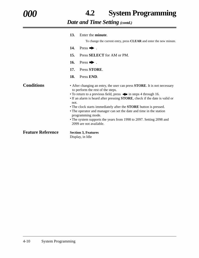
4.2 System ProgrammingDate and Time Setting (contd.)
4-10 System Programming
000
13. Enter the minute.
To change the current entry, press CLEAR and enter the new minute.
14. Press .
15. Press SELECT for AM or PM.
16. Press .
17. Press STORE.
18. Press END.
Conditions • After changing an entry, the user can press STORE. It is not necessaryto perform the rest of the steps.
• To return to a previous field, press in steps 4 through 16.• If an alarm is heard after pressing STORE, check if the date is valid or
not.• The clock starts immediately after the STORE button is pressed.• The operator and manager can set the date and time in the station
programming mode.• The system supports the years from 1998 to 2097. Setting 2098 and
2099 are not available.
Feature Reference Section 3, FeaturesDisplay, in Idle

4.2 System ProgrammingSystem Speed Dialing Entry
001
System Programming 4-11
Description Used to program the System Speed Dialing numbers. Thesenumbers are available to all extension users. There are 100 numbersavailable from 00 to 99.
Selection • Speed dialing number: 00 – 99• Telephone number: 32 digits (max.)
Default All speed dialing numbers – Not stored
Programming 1. Enter 001.
Display: Speed Dialing
2. Press NEXT.
Display: Speed NO? →
3. Enter a speed dialing number.
Pressing NEXT also can enter speed dialing number 00.
Display example: 00:Not Stored
4. Enter a telephone number.
To delete the current entry, press CLEAR.To change the current entry, press CLEAR and enter the newnumber.
5. Press STORE.
6. To program another speed dialing number, press NEXT orPREV, or SELECT and enter the desired speed dialingnumber.
7. Repeat steps 4 through 6.
8. Press END.

4.2 System ProgrammingSystem Speed Dialing Entry (contd.)
4-12 System Programming
001
Conditions • Each speed dialing number has a maximum of 32 digits. The validcharacters are 0 – 9, , and # keys, and the FLASH, PAUSE,SECRET and – (hyphen) buttons.
– To store a flash signal, press FLASH.Note: The stored flash will only be effective during a call in
progress. (Refer to Section 3 “External FeatureAccess”.)
– To store a hyphen, press the “–” button.– To store a pause, press PAUSE.
(Refer to Section 3 “Pause Insertion, Automatic”.)– To store a feature number to convert pulse signals to DTMF
signals, press the and # keys.(Refer to Section 3 “Pulse to Tone Conversion”.)
– To prevent displaying all or part of a number, press INTERCOMbefore and after the confidential parts of the number. (Refer toSection 3 “Secret Dialing”.)
• When storing an external number, include a line access code (9, 81 – 86)before the number. When dialing, a pause will automatically be insertedafter the code.
• When storing an account code, enter the account code after the lineaccess code. Press and then enter the account code.(Refer to Section 3 “Account Code Entry”.)
• It is possible to store a number consisting of 33 digits or more by storingit in two speed dialing numbers. The line access code should be stored inthe first speed dialing number.
• To access another speed dialing number in steps 3 through 6, pressSELECT and start with step 3.
• To display parts of the number which have scrolled off the display, pressor .
Feature Reference Section 3, FeaturesSystem Speed Dialing

4.2 System ProgrammingSystem Password
002
System Programming 4-13
Description Assigns the password required for entering the systemprogramming mode or assigning extension passwords.
Selection Password: 0000 – 9999
Default 1234
Programming 1. Enter 002.
Display: System Password
2. Press NEXT.
Display: Password : 1234
3. Enter a password.
To change the current entry, press CLEAR and enter the newpassword.
4. Press STORE.
5. Press END.
Conditions None
Feature Reference Section 3, Features System Programming with a Proprietary Telephone

4.2 System ProgrammingDSS Console Port Assignment
4-14 System Programming
003
Description Assigns the jack numbers for the DSS Consoles.
Selection • DSS Console number: 1 or 2• Jack number: 02 – 24 / Disable
Default All DSS Consoles — Disable
Programming 1. Enter 003.
Display: DSS Jack Assign
2. Press NEXT.
Display: DSS NO? →
3. Enter a DSS Console number (1 or 2).
Pressing NEXT also can enter DSS Console number 1.
Display example: DSS1:Disable
4. Enter a jack number.
To assign no DSS Console jack, press CLEAR.To delete the current entry, press CLEAR.To change the current entry, press CLEAR and enter the new jacknumber.
5. Press STORE.
6. To program the other DSS Console, press NEXT or PREV.
7. Repeat steps 4 and 5.
8. Press END.
Conditions • Both DSS Consoles cannot be assigned to the same DSS Console jack.• If a single line telephone is assigned as the paired extension, the paired
DSS Console will not function.• Jack 01 is the manager extension, so the jack 01 cannot be assigned as
the DSS Console jack.• Jack numbers assigned as the DSS Console jacks in this program cannot
be assigned in program [004] “Paired Telephone Assignment for DSSConsole”.
Feature Reference Section 3, FeaturesDSS Console (KX-T7040)

4.2 System ProgrammingPaired Telephone Assignment for DSS Console
004
System Programming 4-15
Description Assigns the jack numbers for the paired extensions with DSSConsoles.
Selection • DSS Console number: 1 or 2• Jack number: 01 – 24 / Disable
Default DSS1 – Disable, DSS2 – Disable
Programming 1. Enter 004.
Display: DSS Pair Assign
2. Press NEXT.
Display: DSS NO? →
3. Enter a DSS Console number (1 or 2).
Pressing NEXT also can enter DSS Console number 1.
Display example: DSS1:Disable
4. Enter a jack number.
To assign no DSS Console jack, press CLEAR.To delete the current entry, press CLEAR.To change the current entry, press CLEAR and enter the new jacknumber.
5. Press STORE.
6. To program the other DSS Console, press NEXT or PREV.
7. Repeat steps 4 and 5.
8. Press END.
Conditions • Both telephones cannot be assigned to the same jack.• If a single line telephone is assigned as the paired extension, the paired
DSS Console will not function.• Jack numbers assigned as the paired extensions in this program cannot
be assigned in program [003] “DSS Console Port Assignment”.
Feature Reference Section 3, FeaturesDSS Console (KX-T7040)

4.2 System ProgrammingOne-Touch Transfer Using a DSS Button
4-16 System Programming
005
Description Enables or disables automatically holding an outside call when aDSS button on a DSS Console or proprietary telephone is pressed.Through this assignment, the button can perform the following.• With Transfer — Pressing a DSS button holds an outside call and
quickly transfers it to an extension withoutpressing the TRANSFER button.
• Without Transfer — Pressing the TRANSFER button and then aDSS button will transfer an outside call.
Selection With Transfer / Without Transfer
Default With Transfer
Programming 1. Enter 005.
Display: DSS Mode
2. Press NEXT.
Display example: With Transfer
3. Keep pressing SELECT until the desired selection isdisplayed.
4. Press STORE.
5. Press END.
Condition • This assignment applies to all DSS buttons on all DSS Consoles andproprietary telephones in the system.
Feature Reference Section 3, FeaturesOne-Touch Transfer Using a DSS Button

4.2 System ProgrammingTime (Day/Night/Lunch) Service Changing Mode
006
System Programming 4-17
Description This program is used to determine if the day/night/lunch mode isset automatically or manually.
Selection Man (manual) / Auto (automatic)
Default Manual
Programming 1. Enter 006.
Display: Day/Night Mode
2. Press NEXT.
Display example: Mode Change:Man
3. Keep pressing SELECT until the desired selection isdisplayed.
4. Press STORE.
5. Press END.
Conditions • If automatic is assigned, the day/night/lunch mode is changed at thetime programmed in [007] “Time (Day/Night/Lunch) Service StartTime”. However, if feature number “783#” is entered and the mode ischanged to “lunch”, the mode will not be changed at the programmedtime until feature number “780#” is entered.
• The operator and manager can change the day/night/lunch mode at anytime.
Feature Reference Section 3, FeaturesTime (Day/Night/Lunch) Service

4.2 System ProgrammingTime (Day/Night/Lunch) Service Start Time
4-18 System Programming
007
Description When automatic is programmed in program [006] “Time(Day/Night/Lunch) Service Changing Mode”, this program sets thestarting time on a day of the week basis.
Selection • Day of the week selection:Sunday / Monday / Tuesday / Wednesday / Thursday /Friday / Saturday / (every day of the week)
• Mode: Day / Night / Lunch-S (lunch starting time) /Lunch-E (lunch ending time)
• Hour: 1 – 12 / None (no change)• Minute: 0 – 59• AM / PM
Default Every day of the week — Day – 9:00 AM / Night – 5:00 PM / Lunch-S – None / Lunch-E – None
Programming 1. Enter 007.
Display: Day/Night Time
2. Press NEXT.
Display: Day of The Week
3. Press NEXT or PREV until the desired day of the week isdisplayed.
To assign every day of the week, press instead of NEXT or PREV.
Display example: Sunday
4. Press SELECT.
Display example: Day : 9:00AM
To select another mode, keep pressing SELECT until the desiredselection is displayed.
5. Press .
6. Enter the hour.
To set no change, keep pressing SELECT until “None” is displayedand go to step 11.If SELECT is pressed, the display shows the previous entry. If theprevious setting was “None”, press SELECT to enter the startingtime.To change the current entry, press CLEAR and enter the new time.
7. Press .

4.2 System ProgrammingTime (Day/Night/Lunch) Service Start Time (contd.)
007
System Programming 4-19
8. Enter the minute.To change the current entry, press CLEAR and enter the newminutes.
9. Press .
10. Press SELECT for AM or PM.
11. Press STORE.
12. To program another time service mode, press SELECT.
13. Repeat steps 6 through 11.
14. To program another day of the week, press NEXT or PREV.
15. Repeat steps 4 through 14.
16. Press END.
Conditions • If it is not necessary to change the time service, select “None” in step 6.• To select the desired day, the user can also keep pressing NEXT in step
3. To assign every day of the week to the same selection, press the key in step 3. In this case, the display will show: Every day.
• The day or night mode is interrupted during the lunch mode. After thelunch mode is finished, the day or night mode will start again.
Feature Reference Section 3, FeaturesTime (Day/Night/Lunch) Service

4.2 System ProgrammingOperator Assignment
4-20 System Programming
008
Description Assigns the jack number for the operator. The operator has theability to perform operator services.
Selection Jack number: 01 – 24 / Disable (no operator)
Default Jack-01
Programming 1. Enter 008.
Display: Operator Ext
2. Press NEXT.
Display example: OPT :Jack-01
3. Enter a jack number.
To assign no operator, press CLEAR.To change the current entry, press CLEAR and enter the new jacknumber.
4. Press STORE.
5. Press END.
Conditions None
Feature Reference Section 3, FeaturesOperator

4.2 System ProgrammingExtension Number Assignment
009
System Programming 4-21
Description Assigns an extension number to each extension.
Selection • Jack number: 01 – 24• Extension Number: 100 – 199
Default Jack 01 – 24 = Ext 101 – 124
Programming 1. Enter 009.
Display: Extension No Set
2. Press NEXT.
Display: Jack NO? →
3. Enter a jack number.
Pressing NEXT also can enter jack number 01.
Display: Jack01:Ext101
4. Enter an extension number.
To change the current entry, press CLEAR and enter the newnumber.
5. Press STORE.
6. To program another jack, press NEXT or PREV, orSELECT and enter the desired jack number.
7. Repeat steps 4 through 6.
8. Press END.
Conditions • Program [604] “Extension Name Setting” is used to name theextensions.
• An extension number which has been assigned to one jack cannot beused for another jack. If an assigned number is entered, an alarm tonewill be heard and the entry is invalid.
Feature References Section 3, FeaturesDisplay, Call InformationIntercom Calling

4.2 System ProgrammingLCD Time Display Selection
4-22 System Programming
010
Description Selects how the current time and date will be displayed on aproprietary telephone while it is idle. Either 12 hour or 24 hour(military time) is available.
Selection 12 HOUR / 24 HOUR
Default 12 HOUR
Programming 1. Enter 010.
Display: Time Display
2. Press NEXT.
Display example: 12 HOUR
3. Press SELECT until the desired selection is displayed.
4. Press STORE.
5. Press END.
Condition • Programs [000] “Date and Time Setting” and [007] “Time (Day/Night/Lunch) Service Start Time”, and the Timed Reminder feature areassigned using 12-hour time regardless of this program. The SMDRprintout is also printed using 12-hour time.
Feature Reference Section 3, FeaturesDisplay, in Idle

4.2 System ProgrammingHunting Group Set
100
System Programming 4-23
Description Assigns to enable or disable the station hunting feature for eachextension group.
Selection • Extension group number: 1 – 8, ( = all extension groups)• Disable / Enable
Default All extension groups — Disable
Programming 1. Enter 100.
Display: Hunting Group
2. Press NEXT.
Display: Group NO? →
3. Enter an extension group number.
Pressing NEXT also can enter extension group number 1.
Display example: Group1:Disable
4. Keep pressing SELECT until the desired selection isdisplayed.
5. Press STORE.
6. To program another extension group, press NEXT or PREV,or SELECT and enter the desired extension group number.
7. Repeat steps 4 through 6.
8. Press END.
Conditions • Program [600] “Extension Group Assignment” is used to assign theextension group members.
• To assign all extension groups, press the key in step 3. In this case,the display will show: Group : Mixed.
Feature Reference Section 3, Features Station Hunting

4-24 System Programming
4.2 System ProgrammingStation Hunting Type
101
Description Used to set the Station Hunting type for each extension group.There are two Station Hunting types available: Circular andTerminating. If circular is assigned for a group, all of the extensionsin the group are searched one time until an idle one is found. Ifterminating is assigned, searching stops at the extension which hasthe highest jack number in the group.
Selection • Extension group number: 1 – 8, ( = all extension groups)• Terminate (terminating) / Circular
Default All extension groups – Terminate
Programming 1. Enter 101.
Display: Hunting Type
2. Press NEXT.
Display: Group NO? →
3. Enter an extension group number.
Pressing NEXT also can enter extension group number 1.
Display example: Group1:Terminate
4. Keep pressing SELECT until the desired selection isdisplayed.
5. Press STORE.
6. To program another extension group, press NEXT or PREV,or SELECT and enter the desired extension group number.
7. Repeat steps 4 through 6.
8. Press END.
Conditions • Program [600] “Extension Group Assignment” is used to assign theextension group members.
• If all extensions are busy, a busy tone will be heard.
Feature Reference Section 3, Features Station Hunting

4.2 System ProgrammingVoice Mail Port for KX-TVS75/KX-TVS100
102
System Programming 4-25
Description Enables or disables the jacks which work as the voice mail ports forDTMF transmission to the Panasonic Voice Processing System(KX-TVS75/KX-TVS100).
Selection • Jack number: 07 / 08 / 15 / 16, ( = all jacks)• Enable / Disable
Default All jacks — Disable
Programming 1. Enter 102.
Display: VM Port
2. Press NEXT.
Display: Jack NO? →
3. Enter a jack number.
Pressing NEXT also can enter jack number 07.
Display example: #07:Disable
4. Keep pressing SELECT until the desired selection isdisplayed.
5. Press STORE.
6. To program another jack number, press NEXT or PREV, orSELECT and enter the desired jack number.
7. Repeat steps 4 through 6.
8. Press END.
Condition • To assign all jacks to the same selection, press the key in step 3. Inthis case, the display will show: # :Mixed.
Feature Reference Section 3, Features Voice Mail Integration for KX-TVS75/KX-TVS100
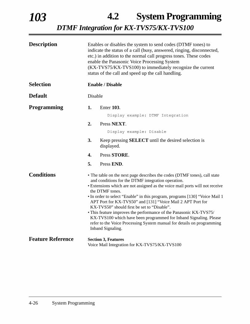
4-26 System Programming
4.2 System ProgrammingDTMF Integration for KX-TVS75/KX-TVS100
103
Description Enables or disables the system to send codes (DTMF tones) toindicate the status of a call (busy, answered, ringing, disconnected,etc.) in addition to the normal call progress tones. These codesenable the Panasonic Voice Processing System(KX-TVS75/KX-TVS100) to immediately recognize the currentstatus of the call and speed up the call handling.
Selection Enable / Disable
Default Disable
Programming 1. Enter 103.
Display example: DTMF Integration
2. Press NEXT.
Display example: Disable
3. Keep pressing SELECT until the desired selection isdisplayed.
4. Press STORE.
5. Press END.
Conditions • The table on the next page describes the codes (DTMF tones), call stateand conditions for the DTMF integration operation.
• Extensions which are not assigned as the voice mail ports will not receivethe DTMF tones.
• In order to select “Enable” in this program, programs [130] “Voice Mail 1APT Port for KX-TVS50” and [131] “Voice Mail 2 APT Port forKX-TVS50” should first be set to “Disable”.
• This feature improves the performance of the Panasonic KX-TVS75/KX-TVS100 which have been programmed for Inband Signaling. Pleaserefer to the Voice Processing System manual for details on programmingInband Signaling.
Feature Reference Section 3, FeaturesVoice Mail Integration for KX-TVS75/KX-TVS100

Call State ConditionsCode
4.2 System ProgrammingDTMF Integration (contd.)
103
System Programming 4-27
1
2
3
4
5
6
7
8
9
#9
Ringback Tone
Busy Tone
Reorder Tone
DND
Answer
Forwarded toVoice ProcessingSystem (Ringing)
Forwarded toVoice Mail (Busy)
Forwarded toExtension
Confirmation Tone
Disconnect
When an extension the Voice Processing System hasdialed is ringing.
When an extension the Voice Processing System hasdialed is busy.
When the Voice Processing System has dialed aninvalid extension number or the Voice ProcessingSystem is inadvertently connected to another VoiceMail Port.
When an extension the Voice Processing System hasdialed sets the DND (Do Not Disturb) feature.
When an extension the Voice Processing System hasdialed answers the call.
When a called extension is forwarded to a VoiceProcessing System, the call can be forwarded toanother available Voice Processing System. In thisway, the first Voice Processing System, typically anAuto-Attendant, can release the call to the other VoiceProcessing System and receive another incoming call.
When a called extension is forwarded to a VoiceProcessing System, a Voice Processing System is notavailable to receive the call.
When a called extension is forwarded to another, non-Voice Processing System extension.
When a Voice Processing System has successfullyturned a message waiting lamp on or off.
When the calling party is disconnected.

Operation
4-28 System Programming
4.2 System ProgrammingHold Mode Selection
104
Hold Mode To hold To transfer
Hold-1
Hold-2
Hold-3
Description Assigns the call hold mode for single line telephones.Each mode is explained as follows.
Selection Hold-1 / Hold-2 / Hold-3
Default Hold-1
Programming 1. Enter 104.
Display: Hold Mode
2. Press NEXT.
Display example: Hold-1
3. Keep pressing SELECT until the desired selection isdisplayed.
4. Press STORE.
5. Press END.
Conditions None
Feature References Section 3, Features Call Hold – IntercomCall Hold – Outside (CO) Line
Flash the hookswitch + on-hook
Flash the hookswitch+ feature number (20) + on-hook
Flash the hookswitch+ feature number (20) + on-hook
Flash the hookswitch + extension number or line access code
Flash the hookswitch + extension number or line access code
Flash the hookswitch + feature number (20) + extension number or line access code

4.2 System ProgrammingConference Tone
105
System Programming 4-29
Description Assigns whether or not a confirmation tone is sent before startingand ending a conference call. This assignment also works for theExecutive Busy Override feature.
Selection Enable / Disable
Default Enable
Programming 1. Enter 105.
Display: Conference Tone
2. Press NEXT.
Display example: Enable
3. Keep pressing SELECT until the desired selection isdisplayed.
4. Press STORE.
5. Press END.
Conditions None
Feature Reference Section 3, Features Conference

4-30 System Programming
4.2 System ProgrammingExternal Paging Access Tone
106
Description Used to remove the confirmation tone for the external pager. Thedefault setting sends confirmation tone to the external pager beforepaging is sent.
Selection Enable / Disable
Default Enable
Programming 1. Enter 106.
Display: Ext-Pag Ack-Tone
2. Press NEXT.
Display example: Page:Enable
3. Keep pressing SELECT until the desired selection isdisplayed.
4. Press STORE.
5. Press END.
Condition • The external pager is a user-supplied item. One external pager can beinstalled to the system.
Feature References Section 3, Features Confirmation TonesPaging — AllPaging — External

4.2 System ProgrammingDTMF Receiver Check
107
System Programming 4-31
Description Enables or disables the DTMF receiver to check whether the DTMFreceivers are activated normally or not.Six DTMF receivers work with the following cards.
DTMF-R 1 and 2 — basic extension card (jacks 01 – 08)DTMF-R 3 and 4 — extension expansion card 1
(jacks 09 – 16)DTMF-R 5 and 6 — extension expansion card 2 (jacks 17 – 24)
Selection • DTMF Receiver number: 1 – 6• Enable / Disable
Default All DTMF receivers — Enable
Programming 1. Enter 107.
Display: DTMF-R Selection
2. Press NEXT.
Display:DTMF-R NO? →
3. Enter the DTMF receiver number.
Pressing NEXT also can enter DTMF receiver number 1.
Display example:DTMF-R1:Enable
4. Keep pressing SELECT until the desired selection isdisplayed.
5. Press STORE.
6. To program another DTMF receiver, press NEXT or PREV,or SELECT and enter the desired DTMF receiver number.
7. Repeat steps 4 through 6.
8. Press END.
Conditions None
Feature References None
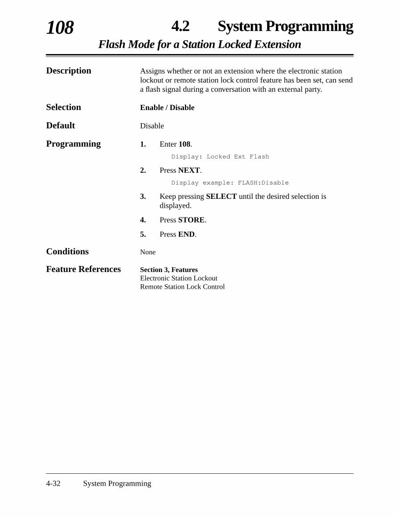
4-32 System Programming
4.2 System ProgrammingFlash Mode for a Station Locked Extension
108
Description Assigns whether or not an extension where the electronic stationlockout or remote station lock control feature has been set, can senda flash signal during a conversation with an external party.
Selection Enable / Disable
Default Disable
Programming 1. Enter 108.
Display: Locked Ext Flash
2. Press NEXT.
Display example: FLASH:Disable
3. Keep pressing SELECT until the desired selection isdisplayed.
4. Press STORE.
5. Press END.
Conditions None
Feature References Section 3, Features Electronic Station LockoutRemote Station Lock Control
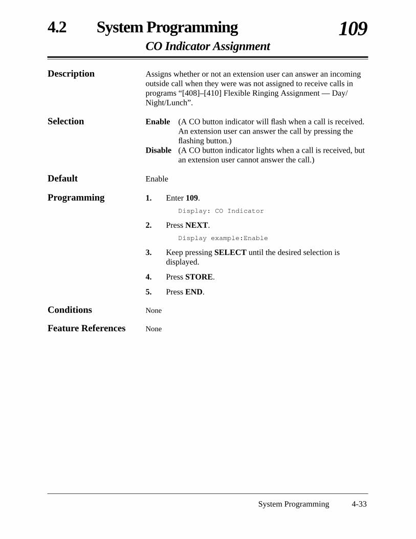
4.2 System ProgrammingCO Indicator Assignment
109
System Programming 4-33
Description Assigns whether or not an extension user can answer an incomingoutside call when they were was not assigned to receive calls inprograms “[408]–[410] Flexible Ringing Assignment — Day/Night/Lunch”.
Selection Enable (A CO button indicator will flash when a call is received.An extension user can answer the call by pressing theflashing button.)
Disable (A CO button indicator lights when a call is received, butan extension user cannot answer the call.)
Default Enable
Programming 1. Enter 109.
Display: CO Indicator
2. Press NEXT.
Display example:Enable
3. Keep pressing SELECT until the desired selection isdisplayed.
4. Press STORE.
5. Press END.
Conditions None
Feature References None
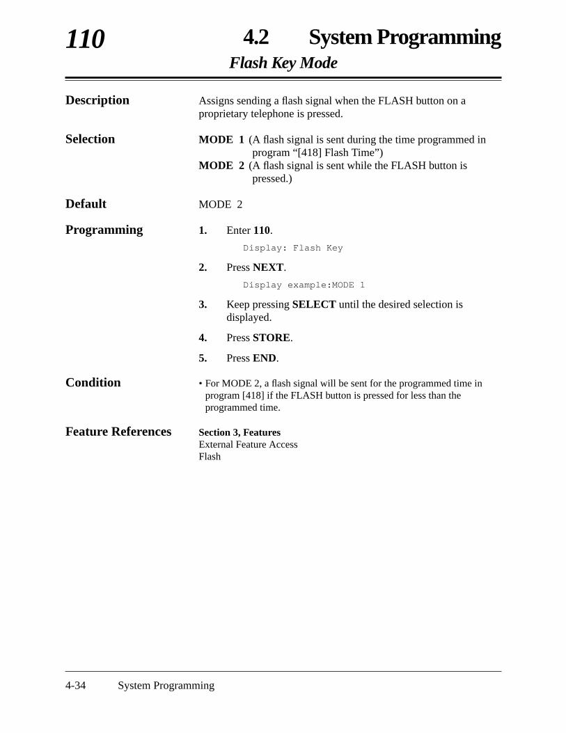
4-34 System Programming
4.2 System ProgrammingFlash Key Mode
110
Description Assigns sending a flash signal when the FLASH button on aproprietary telephone is pressed.
Selection MODE 1 (A flash signal is sent during the time programmed inprogram “[418] Flash Time”)
MODE 2 (A flash signal is sent while the FLASH button ispressed.)
Default MODE 2
Programming 1. Enter 110.
Display: Flash Key
2. Press NEXT.
Display example:MODE 1
3. Keep pressing SELECT until the desired selection isdisplayed.
4. Press STORE.
5. Press END.
Condition • For MODE 2, a flash signal will be sent for the programmed time inprogram [418] if the FLASH button is pressed for less than theprogrammed time.
Feature References Section 3, FeaturesExternal Feature AccessFlash

4.2 System ProgrammingHold Music Selection
111
System Programming 4-35
Description Used to determine the music source use for Music on Hold foroutside calls.
Selection External / Tone
Default External
Programming 1. Enter 111.
Display: Hold Music
2. Press NEXT.
Display example:External
3. Keep pressing SELECT until the desired selection isdisplayed.
4. Press STORE.
5. Press END.
Conditions • The external music source is a user-supplied item. One music source canbe installed.
• If “Tone” is assigned, the following cyclic tone is sent to the heldoutside (CO) line.
Feature Reference Section 3, FeaturesMusic on Hold
1 s

4-36 System Programming
4.2 System ProgrammingDSS Console Indication Mode
112
Description Enables or disables the Busy Lamp Field (BLF) on DSS buttons toindicate the Forward (FWD) or Do Not Disturb (DND) status ofcorresponding extensions.
Selection Enable (FWD/DND — flashing) / Disable (FWD/DND — off)
Default Enable
Programming 1. Enter 112.
Display: DSS Indication
2. Press NEXT.
Display example:Enable
3. Keep pressing SELECT until the desired selection isdisplayed.
4. Press STORE.
5. Press END.
Conditions None
Feature Reference Section 3, Features DSS Console (KX-T7040)
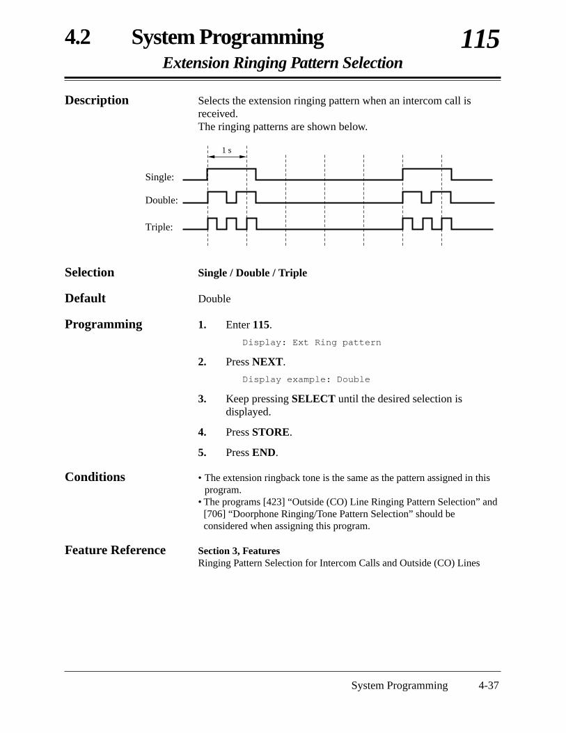
4.2 System ProgrammingExtension Ringing Pattern Selection
115
System Programming 4-37
Description Selects the extension ringing pattern when an intercom call isreceived.The ringing patterns are shown below.
Selection Single / Double / Triple
Default Double
Programming 1. Enter 115.
Display: Ext Ring pattern
2. Press NEXT.
Display example: Double
3. Keep pressing SELECT until the desired selection isdisplayed.
4. Press STORE.
5. Press END.
Conditions • The extension ringback tone is the same as the pattern assigned in thisprogram.
• The programs [423] “Outside (CO) Line Ringing Pattern Selection” and[706] “Doorphone Ringing/Tone Pattern Selection” should beconsidered when assigning this program.
Feature Reference Section 3, Features Ringing Pattern Selection for Intercom Calls and Outside (CO) Lines
1 s
Single:
Double:
Triple:

4-38 System Programming
4.2 System ProgrammingCall Pickup Tone
117
Description Enables or disables the confirmation tone sent when the Call pickupfeature is activated.
Selection Enable / Disable
Default Enable
Programming 1. Enter 117.
Display: Call Pickup Tone
2. Press NEXT.
Display example: Enable
3. Keep pressing SELECT until the desired selection isdisplayed.
4. Press STORE.
5. Press END.
Conditions None
Feature References Section 3, Features Call Pickup, DirectedCall Pickup, Group

4.2 System ProgrammingPulse Restriction
118
System Programming 4-39
Description Enables or disables sending pulse dialing to the Central Officeduring a conversation with an external party, when Pulse or Callblock is selected in program [401] “Dial Mode”.
Selection Enable / Disable
Default Enable
Programming 1. Enter 118.
Display: Pulse Restrict
2. Press NEXT.
Display example: Enable
3. Keep pressing SELECT until the desired selection isdisplayed.
4. Press STORE.
5. Press END.
Conditions None
Feature References None

4-40 System Programming
4.2 System ProgrammingRedialing After Pulse to Tone Conversion
119
Description Enables or disables sending tone dialing to the Central Office whenan extension user redials after changing from pulse to tone mode bypressing and #.
Selection Enable / Disable
Default Disable
Programming 1. Enter 119.
Display: Redial After #
2. Press NEXT.
Display example: Disable
3. Keep pressing SELECT until the desired selection isdisplayed.
4. Press STORE.
5. Press END.
Conditions None
Feature Reference Section 3, Features Pulse to Tone Conversion
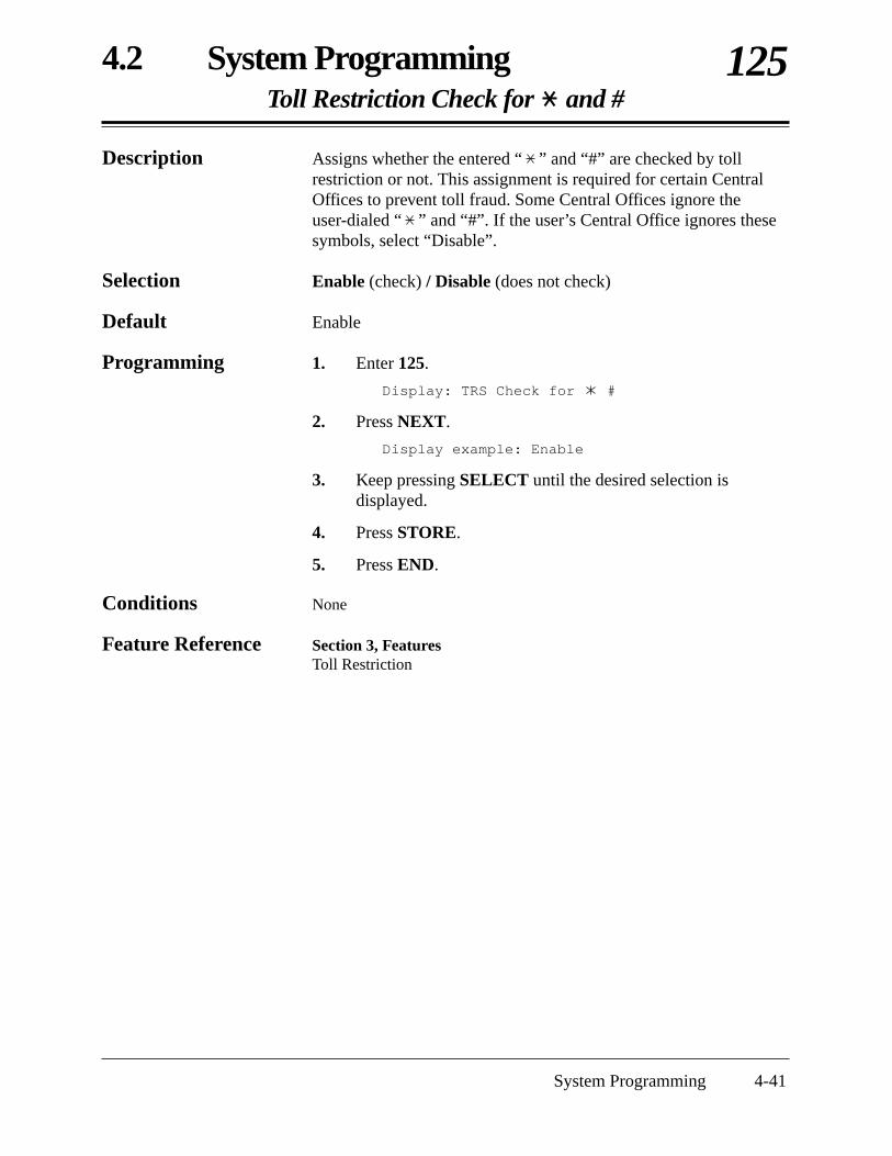
4.2 System ProgrammingToll Restriction Check for and #
125
System Programming 4-41
Description Assigns whether the entered “ ” and “#” are checked by tollrestriction or not. This assignment is required for certain CentralOffices to prevent toll fraud. Some Central Offices ignore theuser-dialed “ ” and “#”. If the user’s Central Office ignores thesesymbols, select “Disable”.
Selection Enable (check) / Disable (does not check)
Default Enable
Programming 1. Enter 125.
Display: TRS Check for #
2. Press NEXT.
Display example: Enable
3. Keep pressing SELECT until the desired selection isdisplayed.
4. Press STORE.
5. Press END.
Conditions None
Feature Reference Section 3, FeaturesToll Restriction

4-42 System Programming
4.2 System ProgrammingVoice Mail 1 APT Port for KX-TVS50 †
130
Description Enables or disables the extension jack numbers 07, or 07 and 08corresponding to the voice mail APT ports for data transmission tothe Panasonic Voice Processing System (KX-TVS50).
Selection • Port 7 / Port 7 & 8 / Disable
Default All jacks — Disable
Programming 1. Enter 130.
Display: VM1(APT)Port
2. Press NEXT.
Display example: Port:Disable
3. Keep pressing SELECT until the desired selection isdisplayed.
4. Press STORE.
5. Press END.
Condition • To change the current assignment from “Port 7” to “Port 7 & 8”, first itmust be changed to “Disable”. Likewise, to change it from “Port 7 & 8”to “Port 7”, first it must be changed to “Disable”. If the currentassignment is already “Disable”, making a change can be done in onestep.
• When “Port 7 & 8” is selected in this program, following programs areautomatically set as described below.
[600] Extension Group Assignment: extension jack number 07 — extension group 7extension jack number 08 — extension group 7
[100] Hunting Group Set: extension group 7 — Enable[101] Station Hunting Type: extension group 7 — Circular[102] Voice Mail Port for KX-TVS75/KX-TVS100:
extension jack number 07 — Enableextension jack number 08 — Enable
• If “Enable” is assigned in program [103] “DTMF Integration forKX-TVS75/TVS100”, “Port 7” or “Port 7 & 8” cannot be selected.
• The extension jacks assigned as the voice mail APT ports in thisprogram are automatically set the Data Line Security.
Feature Reference Section 3, Features Voice Mail Integration for KX-TVS50
† Available when the KX-TA624 is connected to a Proprietary Telephone capable Panasonic Voice Processing System (one thatsupports APT Integration; KX-TVS50).
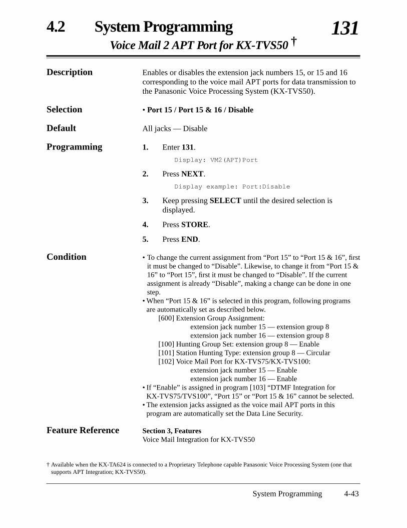
4.2 System ProgrammingVoice Mail 2 APT Port for KX-TVS50 †
131
System Programming 4-43
Description Enables or disables the extension jack numbers 15, or 15 and 16corresponding to the voice mail APT ports for data transmission tothe Panasonic Voice Processing System (KX-TVS50).
Selection • Port 15 / Port 15 & 16 / Disable
Default All jacks — Disable
Programming 1. Enter 131.
Display: VM2(APT)Port
2. Press NEXT.
Display example: Port:Disable
3. Keep pressing SELECT until the desired selection isdisplayed.
4. Press STORE.
5. Press END.
Condition • To change the current assignment from “Port 15” to “Port 15 & 16”, firstit must be changed to “Disable”. Likewise, to change it from “Port 15 &16” to “Port 15”, first it must be changed to “Disable”. If the currentassignment is already “Disable”, making a change can be done in onestep.
• When “Port 15 & 16” is selected in this program, following programsare automatically set as described below.
[600] Extension Group Assignment: extension jack number 15 — extension group 8extension jack number 16 — extension group 8
[100] Hunting Group Set: extension group 8 — Enable[101] Station Hunting Type: extension group 8 — Circular[102] Voice Mail Port for KX-TVS75/KX-TVS100:
extension jack number 15 — Enableextension jack number 16 — Enable
• If “Enable” is assigned in program [103] “DTMF Integration forKX-TVS75/TVS100”, “Port 15” or “Port 15 & 16” cannot be selected.
• The extension jacks assigned as the voice mail APT ports in thisprogram are automatically set the Data Line Security.
Feature Reference Section 3, Features Voice Mail Integration for KX-TVS50
† Available when the KX-TA624 is connected to a Proprietary Telephone capable Panasonic Voice Processing System (one thatsupports APT Integration; KX-TVS50).

4-44 System Programming
4.2 System ProgrammingHold Recall Time
200
Description Assigns the length of the hold recall timer. This timer is used toalert an extension that a call has been held for an extended period oftime.
Selection Time: 30 sec / 1 min / 1.5 min / 2 min / 3 min / 4 min / 5 min /6 min / Disable (= Hold Recall disabled) (seconds/minutes)
Default 30 sec
Programming 1. Enter 200.
Display: Hold Recall Time
2. Press NEXT.
Display example: Time:30 sec
3. Keep pressing SELECT until the desired selection isdisplayed.
4. Press STORE.
5. Press END.
Condition • When “Disable” is selected, the hold alarm is also disabled.
Feature Reference Section 3, FeaturesHold Alarm/Hold Recall

4.2 System ProgrammingTransfer Recall Time
201
System Programming 4-45
Description Assigns the length of the transfer recall timer. If a transferred call isnot answered within the programmed time, the call will be returnedto the original caller.
Selection Time: 15 sec / 30 sec / 1 min / 2 min (seconds/minutes)
Default 30 sec
Programming 1. Enter 201.
Display: Transfer Recall
2. Press NEXT.
Display example: Time:30 sec
3. Keep pressing SELECT until the desired selection isdisplayed.
4. Press STORE.
5. Press END.
Conditions None
Feature Reference Section 3, FeaturesCall Transfer, Unscreened — to Extension

4-46 System Programming
4.2 System ProgrammingCall Forwarding Start Time
202
Description Sets the time for the Call Forwarding – No Answer feature. If a callis not answered within the programmed time, the call will beforwarded to the destination.
Selection 5 sec delay / 10 sec delay / 15 sec delay / 20 sec delay (seconds)
Default 15 sec delay
Programming 1. Enter 202.
Display: Call FWD Delay
2. Press NEXT.
Display example: 15sec delay
3. Keep pressing SELECT until the desired selection isdisplayed.
4. Press STORE.
5. Press END.
Conditions None
Feature Reference Section 3, FeaturesCall Forwarding – Busy/No Answer
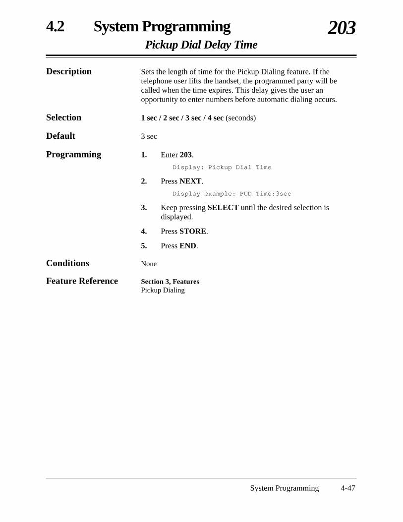
4.2 System ProgrammingPickup Dial Delay Time
203
System Programming 4-47
Description Sets the length of time for the Pickup Dialing feature. If thetelephone user lifts the handset, the programmed party will becalled when the time expires. This delay gives the user anopportunity to enter numbers before automatic dialing occurs.
Selection 1 sec / 2 sec / 3 sec / 4 sec (seconds)
Default 3 sec
Programming 1. Enter 203.
Display: Pickup Dial Time
2. Press NEXT.
Display example: PUD Time:3sec
3. Keep pressing SELECT until the desired selection isdisplayed.
4. Press STORE.
5. Press END.
Conditions None
Feature Reference Section 3, FeaturesPickup Dialing

4-48 System Programming
4.2 System ProgrammingCall Duration Count Start Time
204
Description Sets the number of seconds the system waits between the end ofdialing and the start of the SMDR timer for outgoing toll calls.When the system has sent all the digits to the central office and thistimer expires, the system will start counting the call. A displaytelephone shows the elapsed time of the call. The starting time andthe duration of a call are recorded in the SMDR record.
Selection Instantly / 5 s / 10 s / 15 s / 20 s / 25 s / 30 s / 35 s / 40 s / 45 s /50 s after dial (seconds)
Default 10 s after dial
Programming 1. Enter 204.
Display: Durat-Time Count
2. Press NEXT.
Display example: 5s after dial
3. Keep pressing SELECT until the desired selection isdisplayed.
4. Press STORE.
5. Press END.
Condition • The timer starts counting after all the digits are dialed. This timer doesnot apply to incoming calls. The timer for incoming calls startsimmediately.
Feature References Section 3, FeaturesDisplay, Call InformationStation Message Detail Recording (SMDR)

4.2 System ProgrammingOutside-to-Outside (CO-to-CO) Line Duration Time Limit
205
System Programming 4-49
Description Sets the maximum time allowed for a conversation between twoexternal parties. When the timer expires, the Outside-to-Outside(CO-to-CO) Line call is disconnected.
Selection Time (minutes): 1 – 32
Default 10 min
Programming 1. Enter 205.
Display: CO-CO Dur. Limit
2. Press NEXT.
Display example: Time:10min
3. Enter the time.
To change the current entry, press CLEAR and enter the new time.
4. Press STORE.
5. Press END.
Conditions None
Feature References Section 3, FeaturesCall Forwarding – to an Outside (CO) LineCall Transfer, Screened – to an Outside (CO) LineConference, UnattendedDirect Inward System Access (DISA)

4-50 System Programming
4.2 System ProgrammingDialing Start Time
206
Description Sets the number of milliseconds the system waits before dialingafter an outside (CO) line is seized.
Selection 0 msec / 250 msec / 500 msec / 750 msec / 1000 msec /1250 msec / 1500 msec (milliseconds)
Default 0 msec
Programming 1. Enter 206.
Display: Dial Start Time
2. Press NEXT.
Display example: Time: 0 msec
3. Keep pressing SELECT until the desired selection isdisplayed.
4. Press STORE.
5. Press END.
Conditions None
Feature References Section 3, FeaturesLine Access, AutomaticLine Access, DirectLine Access, Individual

4.2 System ProgrammingInterdigit Time
208
System Programming 4-51
Description Assigns the maximum time allowed between digits for an outgoingoutside call.
Selection 5 sec / 10 sec / 15 sec (seconds)
Default 10 sec
Programming 1. Enter 208.
Display: Interdigit Time
2. Press NEXT.
Display example: Time:10 sec
3. Keep pressing SELECT until the desired selection isdisplayed.
4. Press STORE.
5. Press END.
Conditions • The interdigit timer applies until the toll restriction check is completed.When the timer expires, an outgoing outside call will be disconnectedwhile dialing, if “Enable” was selected in program [211] “No DialDisconnection”.
• For a single line telephone, an outgoing outside call will be releasedfrom a DTMF receiver when the interdigit timer expires.
Feature Reference Section 3, FeaturesToll Restriction

4-52 System Programming
4.2 System ProgrammingNo Dial Disconnection
211
Description Enables or disables disconnecting an outside (CO) line if anextension user does not dial anything within 10 seconds after anoutside (CO) line is seized.
Selection Enable (disconnect) / Disable (does not disconnect)
Default Disable
Programming 1. Enter 211.
Display: No Dial Mode
2. Press NEXT.
Display example: Disable
3. Keep pressing SELECT until the desired selection isdisplayed.
4. Press STORE.
5. Press END.
Condition • The interdigit timer assigned in program [208] “Interdigit Time” appliesuntil the toll restriction check is completed. When the timer expires, anoutgoing outside call will be disconnected while dialing, if “Enable”was selected in this program.
Feature References None

4.2 System ProgrammingCarrier Code Assignment
300
System Programming 4-53
Description Assigns carrier codes. This allows the system to recognize a specialuser-dialed carrier code in order to apply toll restriction. Thesystem disregards the assigned code and toll restriction is applied tothe numbers after the code.
Selection • Code number: 01 – 20• Carrier code number: 10 digits (max.)
Default All codes – Not stored
Programming 1. Enter 300.
Display: Carrier Excepted
2. Press NEXT.
Display: CODE NO? →
3. Enter a code number.
Pressing NEXT also can enter code number 01.
Display example: 01:Not Stored
4. Enter a carrier code number.
To delete the current entry, press CLEAR.To change the current entry, press CLEAR and enter the newnumber.
5. Press STORE.
6. To program another code, press NEXT or PREV, orSELECT and enter the desired code number.
7. Repeat steps 4 through 6.
8. Press END.
Condition • Each carrier code number has a maximum of ten digits, consisting of0 – 9, , # and x (PAUSE button). The character “x” can be used as awild card character and is entered by pressing the PAUSE button.
Feature References Section 3, FeaturesPause Insertion, AutomaticToll Restriction for Special Carrier Access

4-54 System Programming
4.2 System ProgrammingToll Restriction — System Speed Dialing Boundary Class
301
Description Assigns the Toll Restriction class for System Speed Dialingnumbers.
Selection Boundary Class-1 / Boundary Class-2 / Boundary Class-3 /Boundary Class-4 / Boundary Class-5
Default Boundary Class-1
Programming 1. Enter 301.
Display: SSD Boundary
2. Press NEXT.
Display example: Boundary Class-1
3. Keep pressing SELECT until the desired selection isdisplayed.
4. Press STORE.
5. Press END.
Conditions None
Feature Reference Section 3, FeaturesToll Restriction for System Speed Dialing
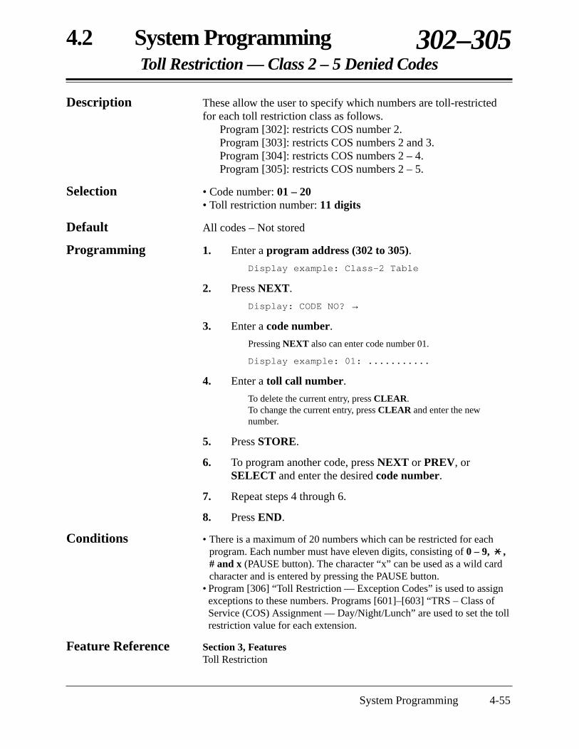
4.2 System ProgrammingToll Restriction — Class 2 – 5 Denied Codes
302–305
System Programming 4-55
Description These allow the user to specify which numbers are toll-restrictedfor each toll restriction class as follows.
Program [302]: restricts COS number 2.Program [303]: restricts COS numbers 2 and 3.Program [304]: restricts COS numbers 2 – 4.Program [305]: restricts COS numbers 2 – 5.
Selection • Code number: 01 – 20• Toll restriction number: 11 digits
Default All codes – Not stored
Programming 1. Enter a program address (302 to 305).
Display example: Class-2 Table
2. Press NEXT.
Display: CODE NO? →
3. Enter a code number.
Pressing NEXT also can enter code number 01.
Display example: 01: ...........
4. Enter a toll call number.
To delete the current entry, press CLEAR.To change the current entry, press CLEAR and enter the newnumber.
5. Press STORE.
6. To program another code, press NEXT or PREV, orSELECT and enter the desired code number.
7. Repeat steps 4 through 6.
8. Press END.
Conditions • There is a maximum of 20 numbers which can be restricted for eachprogram. Each number must have eleven digits, consisting of 0 – 9, ,# and x (PAUSE button). The character “x” can be used as a wild cardcharacter and is entered by pressing the PAUSE button.
• Program [306] “Toll Restriction — Exception Codes” is used to assignexceptions to these numbers. Programs [601]–[603] “TRS – Class ofService (COS) Assignment — Day/Night/Lunch” are used to set the tollrestriction value for each extension.
Feature Reference Section 3, FeaturesToll Restriction
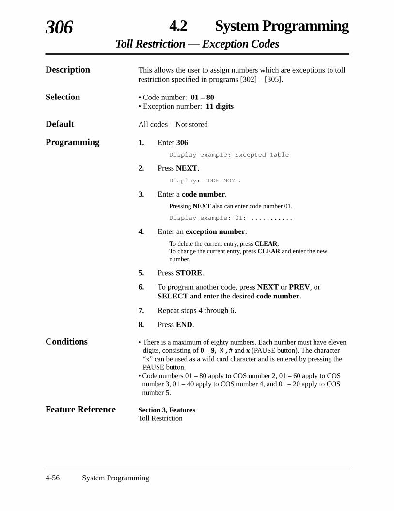
4-56 System Programming
4.2 System ProgrammingToll Restriction — Exception Codes
306
Description This allows the user to assign numbers which are exceptions to tollrestriction specified in programs [302] – [305].
Selection • Code number: 01 – 80• Exception number: 11 digits
Default All codes – Not stored
Programming 1. Enter 306.
Display example: Excepted Table
2. Press NEXT.
Display: CODE NO?→
3. Enter a code number.
Pressing NEXT also can enter code number 01.
Display example: 01: ...........
4. Enter an exception number.
To delete the current entry, press CLEAR.To change the current entry, press CLEAR and enter the newnumber.
5. Press STORE.
6. To program another code, press NEXT or PREV, orSELECT and enter the desired code number.
7. Repeat steps 4 through 6.
8. Press END.
Conditions • There is a maximum of eighty numbers. Each number must have elevendigits, consisting of 0 – 9, , # and x (PAUSE button). The character“x” can be used as a wild card character and is entered by pressing thePAUSE button.
• Code numbers 01 – 80 apply to COS number 2, 01 – 60 apply to COSnumber 3, 01 – 40 apply to COS number 4, and 01 – 20 apply to COSnumber 5.
Feature Reference Section 3, FeaturesToll Restriction

4.2 System ProgrammingEmergency Dial Number Set
309
System Programming 4-57
Description Stores up to five emergency numbers.Emergency numbers are not subject to toll restriction, AccountCode – Forced/Verify - All modes, Electronic Station Lockout orRemote Station Lock Control.
Selection • Code number: 1 – 5• Emergency number: 11 digits (max.)
Default Code-01 = 911, Other Codes = Not stored
Programming 1. Enter 309.
Display: Emergency Code
2. Press NEXT.
Display: CODE NO? →
3. Enter a code number.
Pressing NEXT also can enter code number 1.
Display example: CODE-01:
4. Enter an emergency number.
To delete the current entry, press CLEAR.To change the current entry, press CLEAR and enter the newnumber.
5. Press STORE.
6. To program another code, press NEXT or PREV, orSELECT and enter the desired code number.
7. Repeat steps 4 through 6.
8. Press END.
Condition • Each emergency number has a maximum of eleven digits, consisting of0 – 9.
Feature References Section 3, FeaturesAccount Code EntryElectronic Station LockoutEmergency CallRemote Station Lock ControlToll Restriction

4-58 System Programming
4.2 System ProgrammingAccount Codes
310
Description Assigns the account codes for Account Code Entry, Verify – Alland Verify – Toll modes. If Verify – All is assigned in program[605] “Account Code Entry Mode”, an account code is required tomake an outside call. If Verify – Toll is assigned, an account code isonly required to override toll restriction.
Selection • Code number: 01 – 24• Account code: 4 digits
Default All codes – Not stored
Programming 1. Enter 310.
Display: Account Code
2. Press NEXT.
Display: CODE NO? →
3. Enter a code number.
Pressing NEXT also can enter code number 01.
Display example: CODE-01:....
4. Enter an account code.
To delete the current entry, press CLEAR.To change the current entry, press CLEAR and enter the new accountcode.
5. Press STORE.
6. To program another code number, press NEXT or PREV, orSELECT and enter the desired code number.
7. Repeat steps 4 through 6.
8. Press END.
Conditions • Each verifiable account code has 4 digits, consisting of 0 – 9.• Program [605] “Account Code Entry Mode” is used to select the
Account Code Entry mode.
Feature References Section 3, Features Account Code EntryToll Restriction Override by Account Codes
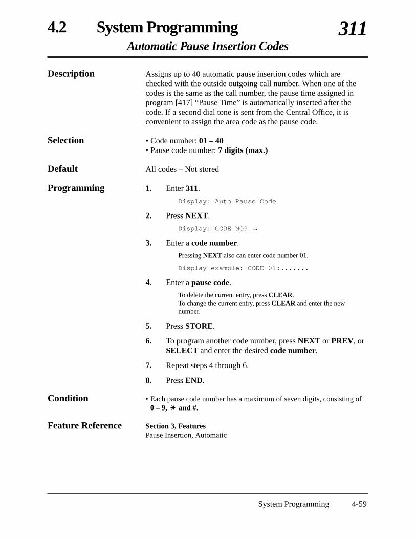
4.2 System ProgrammingAutomatic Pause Insertion Codes
311
System Programming 4-59
Description Assigns up to 40 automatic pause insertion codes which arechecked with the outside outgoing call number. When one of thecodes is the same as the call number, the pause time assigned inprogram [417] “Pause Time” is automatically inserted after thecode. If a second dial tone is sent from the Central Office, it isconvenient to assign the area code as the pause code.
Selection • Code number: 01 – 40• Pause code number: 7 digits (max.)
Default All codes – Not stored
Programming 1. Enter 311.
Display: Auto Pause Code
2. Press NEXT.
Display: CODE NO? →
3. Enter a code number.
Pressing NEXT also can enter code number 01.
Display example: CODE-01:.......
4. Enter a pause code.
To delete the current entry, press CLEAR.To change the current entry, press CLEAR and enter the newnumber.
5. Press STORE.
6. To program another code number, press NEXT or PREV, orSELECT and enter the desired code number.
7. Repeat steps 4 through 6.
8. Press END.
Condition • Each pause code number has a maximum of seven digits, consisting of0 – 9, and #.
Feature Reference Section 3, Features Pause Insertion, Automatic

4-60 System Programming
4.2 System ProgrammingToll Restriction — Station Lock Boundary Class
312
Description Assigns the Toll Restriction COS number when the ElectronicStation Lockout or Remote Station Lock Control is set.
Selection COS-2 / COS-3 / COS-4 / COS-5 / Disable
Default Disable
Programming 1. Enter 312.
Display: LOCK Boundary
2. Press NEXT.
Display example: Boundary Disable
3. Keep pressing SELECT until the desired selection isdisplayed.
4. Press STORE.
5. Press END.
Conditions None
Feature References Section 3, FeaturesElectronic Station LockoutRemote Staiton Lock ControlToll Restriction — Station Lock Boundary Class
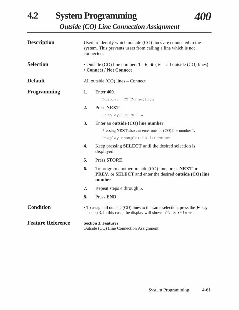
4.2 System ProgrammingOutside (CO) Line Connection Assignment
400
System Programming 4-61
Description Used to identify which outside (CO) lines are connected to thesystem. This prevents users from calling a line which is notconnected.
Selection • Outside (CO) line number: 1 – 6, ( = all outside (CO) lines)• Connect / Not Connect
Default All outside (CO) lines – Connect
Programming 1. Enter 400.
Display: CO Connection
2. Press NEXT.
Display: CO NO? →
3. Enter an outside (CO) line number.
Pressing NEXT also can enter outside (CO) line number 1.
Display example: CO 1:Connect
4. Keep pressing SELECT until the desired selection isdisplayed.
5. Press STORE.
6. To program another outside (CO) line, press NEXT orPREV, or SELECT and enter the desired outside (CO) linenumber.
7. Repeat steps 4 through 6.
8. Press END.
Condition • To assign all outside (CO) lines to the same selection, press the keyin step 3. In this case, the display will show: CO :Mixed.
Feature Reference Section 3, FeaturesOutside (CO) Line Connection Assignment

4-62 System Programming
4.2 System ProgrammingDial Mode
401
Description Each outside (CO) line can be programmed for DTMF, pulse or callblocking. This program assigns the selection to each line.
DTMF: The dialing signals from an extension, either tone or pulse, areconverted to tone signals and transmitted to an outside (CO) line.
Pulse: The dialing signals from an extension, either tone or pulse, areconverted to pulse signals and transmitted to an outside (CO) line.
Call Blocking: If the Central Office can receive both DTMF and pulse signals butthe user is contracted for pulse, select this mode. When dialing witha touch tone telephone, only the pulse signals are sent to an outside(CO) line.
Selection • Outside (CO) line number: 1 – 6, ( = all outside (CO) lines)• DTMF Mode / Pulse Mode / C.BLK Mode (Call Blocking)
Default All outside (CO) lines — DTMF Mode
Programming 1. Enter 401.
Display: CO Dial Mode
2. Press NEXT.
Display: CO NO? →
3. Enter an outside (CO) line number.
Pressing NEXT also can enter outside (CO) line number 1.
Display example: CO 1:DTMF Mode
4. Keep pressing SELECT until the desired selection isdisplayed.
5. Press STORE.
6. To program another outside (CO) line, press NEXT orPREV, or SELECT and enter the desired outside (CO) linenumber.
7. Repeat steps 4 through 6.
8. Press END.
Conditions • To assign all outside (CO) lines to the same selection, press the keyin step 3. In this case, the display will show: CO :Mixed.
• If pulse or call blocking is assigned, set the line pulse speed in program[402] “Pulse Speed Selection”.
Feature Reference Section 3, FeaturesDial Type Selection
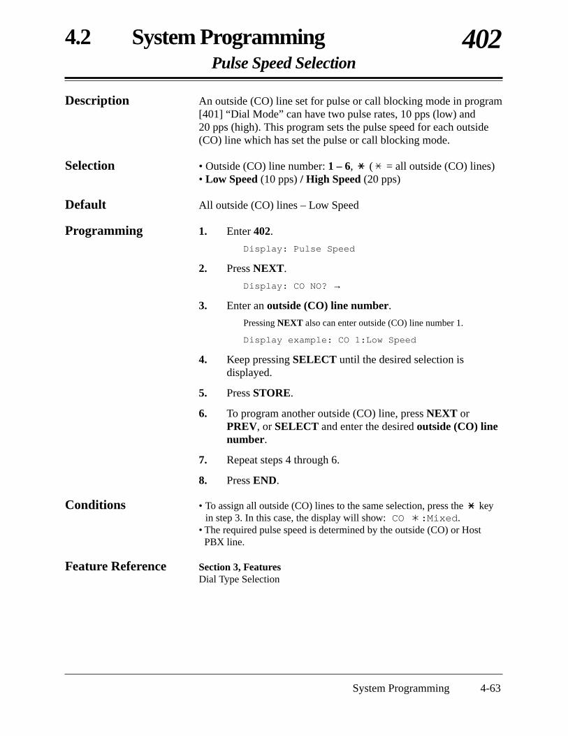
4.2 System ProgrammingPulse Speed Selection
402
System Programming 4-63
Description An outside (CO) line set for pulse or call blocking mode in program[401] “Dial Mode” can have two pulse rates, 10 pps (low) and20 pps (high). This program sets the pulse speed for each outside(CO) line which has set the pulse or call blocking mode.
Selection • Outside (CO) line number: 1 – 6, ( = all outside (CO) lines)• Low Speed (10 pps) / High Speed (20 pps)
Default All outside (CO) lines – Low Speed
Programming 1. Enter 402.
Display: Pulse Speed
2. Press NEXT.
Display: CO NO? →
3. Enter an outside (CO) line number.
Pressing NEXT also can enter outside (CO) line number 1.
Display example: CO 1:Low Speed
4. Keep pressing SELECT until the desired selection isdisplayed.
5. Press STORE.
6. To program another outside (CO) line, press NEXT orPREV, or SELECT and enter the desired outside (CO) linenumber.
7. Repeat steps 4 through 6.
8. Press END.
Conditions • To assign all outside (CO) lines to the same selection, press the keyin step 3. In this case, the display will show: CO :Mixed.
• The required pulse speed is determined by the outside (CO) or HostPBX line.
Feature Reference Section 3, FeaturesDial Type Selection

4-64 System Programming
4.2 System ProgrammingHost PBX Access Codes
403
Description Assigns Host PBX access codes. If the system is installed behind ahost PBX system, an access code is required to make an outsidecall. Up to eight codes can be stored for an outside (CO) lineconnected to the host PBX.
Selection • Outside (CO) line number: 1 – 6, ( = all outside (CO) lines)• Access code: 1 or 2 digits, eight different entries (max.)
Default All outside (CO) lines – Not stored
Programming 1. Enter 403.
Display: Host PBX Access
2. Press NEXT.
Display: CO NO? →
3. Enter an outside (CO) line number.
Pressing NEXT also can enter outside (CO) line number 1.
Display example: CO 1:Not Stored
4. Enter an access code.
To delete the current entry, press CLEAR.To change the current entry, press CLEAR and enter the new accesscode.
Display example: CO 1:01
5. To enter more access codes for the same outside (CO) line,press “,” (CONF/SAVE button) and enter the access codesuntil all of the required entries are completed.
Display example: CO 1:01,08,10,22
6. Press STORE.
7. To program another outside (CO) line, press NEXT orPREV, or SELECT and enter the desired outside (CO) linenumber.
8. Repeat steps 4 through 7.
9. Press END.

4.2 System ProgrammingHost PBX Access Codes (contd.)
403
System Programming 4-65
Conditions • This program is only required if a host PBX is connected to the system.• There is a maximum of eight access codes per outside (CO) line. Each
code has one or two digits, consisting of 0 – 9.• When the programmed codes are dialed, Automatic Pause Insertion and
Toll Restriction are applied to all calls. The programmed pause time (inprogram [417] “Pause Time”) is automatically inserted after the accesscode.
• To assign all outside (CO) lines to the same selection, press the keyin step 3. In this case, the display will show: CO :Mixed.
Feature References Section 3, FeaturesExternal Feature Access Pause Insertion, AutomaticHost PBX Access

4-66 System Programming
4.2 System ProgrammingOutside (CO) Line Group Assignment
404
Description Each outside (CO) line must be assigned to an outside (CO) linegroup (trunk group). This program defines the outside (CO) linegroup assignment for each outside (CO) line. For example, if thereare multiple telephone service companies available, the outside(CO) lines can be grouped by company.
Selection • Outside (CO) line number: 1 – 6, ( = all outside (CO) lines)• Outside (CO) line group (Trunk) number: 1 – 6
Default CO1 — TRK GRP-1; CO5 — TRK GRP-5;CO2 — TRK GRP-2; CO6 — TRK GRP-6CO3 — TRK GRP-3;CO4 — TRK GRP-4;
Programming 1. Enter 404.
Display: Trunk Group
2. Press NEXT.
Display: CO NO? →
3. Enter an outside (CO) line number.
Pressing NEXT also can enter outside (CO) line number 1.
Display example: CO 1:TRK GRP-1
4. Enter the outside (CO) line group number.
To change the current entry, enter the new outside (CO) line groupnumber.
5. Press STORE.
6. To program another outside (CO) line, press NEXT orPREV, or SELECT and enter the desired outside (CO) linenumber.
7. Repeat steps 4 through 6.
8. Press END.
Condition • To assign all outside (CO) lines to the same outside (CO) line group,press the key in step 3. In this case, the display will show:CO :Mixed.
Feature Reference Section 3, FeaturesOutside (CO) Line Group

4.2 System ProgrammingFlexible Outward Dialing Assignment — Day/Night/Lunch
405–407
System Programming 4-67
Description Determines which outside (CO) lines can be accessed by anextension in the day, night and lunch modes. The extension userscan make outgoing outside calls using the assigned outside (CO)lines.
Selection • Outside (CO) line number: 1 – 6, ( = all outside (CO) lines)• Jack number: 01 – 24, ( = all jacks)• Enable / Disable
Default All outside (CO) lines – Enable — Day/Night/Lunch
Programming 1. Enter a program address (405 for day, 406 for night or 407for lunch).
Display example: Day Out CO
2. Press NEXT.
Display: CO NO? →
3. Enter an outside (CO) line number.
Pressing NEXT also can enter outside (CO) line number 1.
Display example: CO 1:#01:Enable
4. Enter the desired jack number after pressing the # key.
The user can also keep pressing or until the desired jacknumber is displayed.
5. Keep pressing SELECT until the desired selection isdisplayed.
6. Press STORE.
7. To program another jack, press or , or # and enter thedesired jack number.
8. Repeat steps 5 through 7.
9. To program another outside (CO) line, press NEXT orPREV, or SELECT and the desired outside (CO) linenumber.
10. Repeat steps 4 through 9.
11. Press END.
Condition • To assign all jacks or outside (CO) lines to the same selection, press thekey in step 3 or 4. In these cases, the display will show:
CO :# :Mixed.
Feature References Section 3, FeaturesOutside (CO) Line Connection Assignment – OutgoingTime (Day/Night/Lunch) Service
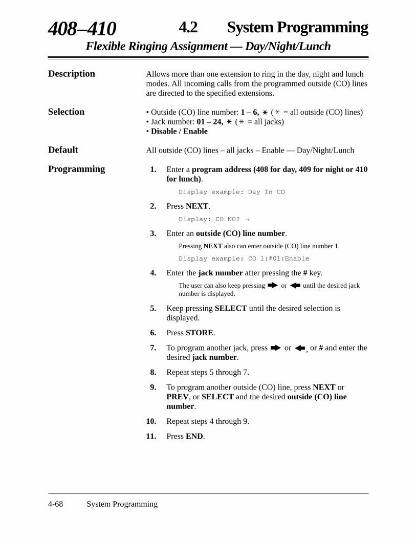
4-68 System Programming
4.2 System ProgrammingFlexible Ringing Assignment — Day/Night/Lunch
408–410
Description Allows more than one extension to ring in the day, night and lunchmodes. All incoming calls from the programmed outside (CO) linesare directed to the specified extensions.
Selection • Outside (CO) line number: 1 – 6, ( = all outside (CO) lines)• Jack number: 01 – 24, ( = all jacks)• Disable / Enable
Default All outside (CO) lines – all jacks – Enable — Day/Night/Lunch
Programming 1. Enter a program address (408 for day, 409 for night or 410for lunch).
Display example: Day In CO
2. Press NEXT.
Display: CO NO? →
3. Enter an outside (CO) line number.
Pressing NEXT also can enter outside (CO) line number 1.
Display example: CO 1:#01:Enable
4. Enter the jack number after pressing the # key.
The user can also keep pressing or until the desired jacknumber is displayed.
5. Keep pressing SELECT until the desired selection isdisplayed.
6. Press STORE.
7. To program another jack, press or , or # and enter thedesired jack number.
8. Repeat steps 5 through 7.
9. To program another outside (CO) line, press NEXT orPREV, or SELECT and the desired outside (CO) linenumber.
10. Repeat steps 4 through 9.
11. Press END.

4.2 System ProgrammingFlexible Ringing Assignment — Day/Night/Lunch (contd.)
408–410
System Programming 4-69
Conditions • An extension can be assigned as the destination for as many outside(CO) lines required.
• To assign all jacks or all outside (CO) lines to the same selection, pressthe key in step 3 or step 4. In these cases, the display will show:CO :# :Mixed.
Feature References Section 3, FeaturesRinging, DelayedTime (Day/Night/Lunch) Service

4-70 System Programming
4.2 System ProgrammingDelayed Ringing Assignment — Day/Night/Lunch
411–413
Description Assigns the ringing start time for each jack in the day, night andlunch modes.
Selection • Outside (CO) line number: 1 – 6, ( = all outside (CO) lines)• Jack number: 01 – 24, ( = all jacks)• Immdtly (immediate ringing) / 5 sec / 10 sec / 15 sec
Default All outside (CO) lines – all jacks – Immdtly — Day/Night/Lunch
Programming 1. Enter a program address (411 for day, 412 for night or 413for lunch).
Display example: Day Delayed CO
2. Press NEXT.
Display: CO NO? →
3. Enter an outside (CO) line number.
Pressing NEXT also can enter outside (CO) line number 1.
Display example: CO 1:#01:Immdtly
4. Enter a jack number after pressing the # key.
The user can also keep pressing or until the desired outside(CO) line number is displayed.
5. Keep pressing SELECT until the desired selection isdisplayed.
6. Press STORE.
7. To program another jack, press or , or # and enter thedesired jack number.
8. Repeat steps 5 through 7.
9. To program another outside (CO) line, press NEXT orPREV, or SELECT and the desired outside (CO) linenumber.
10. Repeat steps 4 through 9.
11. Press END.

4.2 System ProgrammingDelayed Ringing Assignment — Day/Night/Lunch (contd.)
411–413
System Programming 4-71
Conditions • To assign all jacks or outside (CO) lines to the same selection, press thekey in step 3 or step 4. In these cases, the display will show:
CO :# :Mixed.• There are four notification methods.
(1) Immediate ringing: rings immediately(2) 5 second delay(3) 10 second delay(4) 15 second delay
Feature References Section 3, FeaturesRinging, DelayedTime (Day/Night/Lunch) Service

4-72 System Programming
4.2 System ProgrammingOutside (CO) Line Mode — Day/Night/Lunch
414–416
Description Selects the mode of an incoming outside call on each outside (CO)line in the day, night and lunch modes. There are the following fourmodes.Normal: an incoming outside call will be received at the
extension(s) assigned in programs [408]–[410].DIL: an incoming outside call will be received at the assigned
extension.DISA1: an incoming outside call will be received at an extension
through the DISA feature. A caller will hear a tone or anoutgoing message.
DISA2: an incoming outside call will be received at an extensionthrough the DISA feature. A caller might hear OGM 2;for various configurations please see Cases 2, 3 and 4 inSection 3, Features “Outgoing Message (OGM)”.
Selection • Outside (CO) line number: 1 – 6, ( = all outside (CO) lines)• Normal / DIL + extension jack number / DISA1 / DISA2
Default Normal
Programming 1. Enter a program address (414 for day, 415 for night or 416for lunch).
Display example: CO Day/Mode
2. Press NEXT.
Display: CO NO? →
3. Enter an outside (CO) line number.
Pressing NEXT also can enter outside (CO) line number 1.
Display example: CO 1:Normal
4. Keep pressing SELECT until the desired selection isdisplayed and if “DIL” is selected, enter the extension jacknumber.
5. Press STORE.
6. To program another outside (CO) line, press NEXT orPREV, or SELECT and enter the desired outside (CO) linenumber.
7. Repeat steps 4 through 6.
8. Press END.

4.2 System ProgrammingOutside (CO) Line Mode — Day/Night/Lunch (contd.)
414–416
System Programming 4-73
Conditions • “DISA1” must be selected when an optional OGM/FAX Detection cardis not installed and if the user wants to use Internal DISA.
• There are two outgoing messages. Program [502] determines how eachmessage is used.
• To assign all the outside (CO) lines to the same selection, press the key in step 3. In this case, the display will show: CO :Mixed.
Feature References Section 3, FeaturesDirect Inward System Access (DISA)Outgoing Message (OGM)

4-74 System Programming
4.2 System ProgrammingPause Time
417
Description Assigns the length of the pause time. The programmed pause timeis automatically inserted after a line access code or host PBX accesscode programmed in [403] “Host PBX Access Codes”, or can bemanually inserted by the user with the PAUSE button.
Selection • Outside (CO) line number: 1 – 6, ( = all outside (CO) lines)• Time (seconds): 1.5 sec / 2.5 sec / 3.5 sec / 4.5 sec
Default All outside (CO) lines — 1.5 sec
Programming 1. Enter 417.
Display: Pause Time
2. Press NEXT.
Display: CO NO? →
3. Enter an outside (CO) line number.
Pressing NEXT also can enter outside (CO) line number 1.
Display example: CO 1:1.5sec
4. Keep pressing SELECT until the desired time is displayed.
5. Press STORE.
6. To program another outside (CO) line, press NEXT orPREV, or SELECT and enter the desired outside (CO) linenumber.
7. Repeat steps 4 through 6.
8. Press END.
Condition • To assign all outside (CO) lines to the same selection, press the keyin step 3. In this case, the display will show: CO :Mixed.
Feature References Section 3, FeaturesHost PBX AccessPause Insertion, Automatic

4.2 System ProgrammingFlash Time
418
System Programming 4-75
Description Assigns the length of the flash time. If the system is installedbehind a host PBX, External Feature Access (EFA) is necessary toobtain its services. To enable this feature, select the requiredhooking signal sending time for an outside (CO) line.
Selection • Outside (CO) line number: 1 – 6, ( = all outside (CO) lines)• Time (milliseconds): 80 ms / 100 ms / 160 ms / 300 ms / 600 ms /
900 ms / 1200 ms
Default All outside (CO) lines – 600 ms
Programming 1. Enter 418.
Display: Flash Time Set
2. Press NEXT.
Display: CO NO? →
3. Enter an outside (CO) line number.
Pressing NEXT also can enter outside (CO) line number 1.
Display example: CO 1: 600ms
4. Keep pressing SELECT until the desired time is displayed.
5. Press STORE.
6. To program another outside (CO) line, press NEXT orPREV, or SELECT and enter the desired outside (CO) linenumber.
7. Repeat steps 4 through 6.
8. Press END.
Conditions • The required flash time is determined by the central office or host PBXlines.
• To assign all outside (CO) lines to the same selection, press the keyin step 3. In this case, the display will show: CO :Mixed.
Feature References Section 3, FeaturesExternal Feature AccessFlash
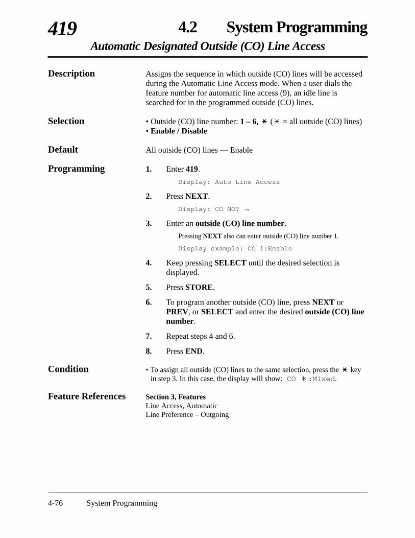
4-76 System Programming
4.2 System ProgrammingAutomatic Designated Outside (CO) Line Access
419
Description Assigns the sequence in which outside (CO) lines will be accessedduring the Automatic Line Access mode. When a user dials thefeature number for automatic line access (9), an idle line issearched for in the programmed outside (CO) lines.
Selection • Outside (CO) line number: 1 – 6, ( = all outside (CO) lines)• Enable / Disable
Default All outside (CO) lines — Enable
Programming 1. Enter 419.
Display: Auto Line Access
2. Press NEXT.
Display: CO NO? →
3. Enter an outside (CO) line number.
Pressing NEXT also can enter outside (CO) line number 1.
Display example: CO 1:Enable
4. Keep pressing SELECT until the desired selection isdisplayed.
5. Press STORE.
6. To program another outside (CO) line, press NEXT orPREV, or SELECT and enter the desired outside (CO) linenumber.
7. Repeat steps 4 and 6.
8. Press END.
Condition • To assign all outside (CO) lines to the same selection, press the keyin step 3. In this case, the display will show: CO :Mixed.
Feature References Section 3, Features Line Access, AutomaticLine Preference – Outgoing
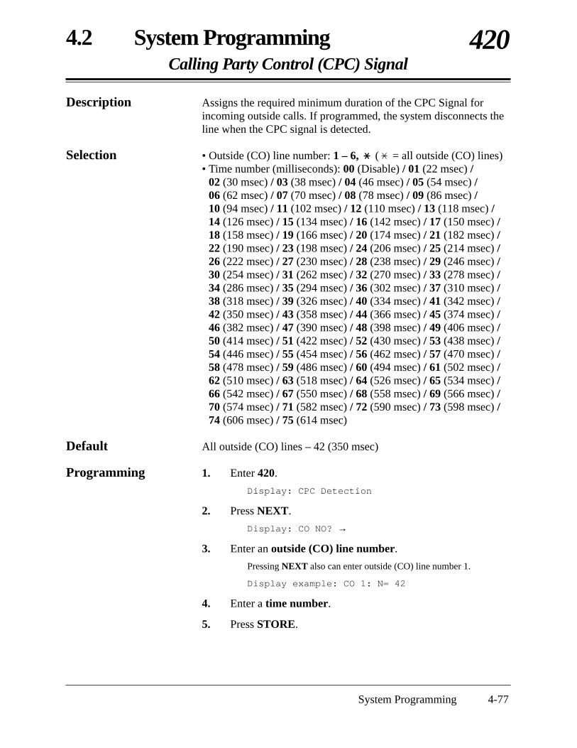
4.2 System ProgrammingCalling Party Control (CPC) Signal
420
System Programming 4-77
Description Assigns the required minimum duration of the CPC Signal forincoming outside calls. If programmed, the system disconnects theline when the CPC signal is detected.
Selection • Outside (CO) line number: 1 – 6, ( = all outside (CO) lines)• Time number (milliseconds): 00 (Disable) / 01 (22 msec) /
02 (30 msec) / 03 (38 msec) / 04 (46 msec) / 05 (54 msec) / 06 (62 msec) / 07 (70 msec) / 08 (78 msec) / 09 (86 msec) / 10 (94 msec) / 11 (102 msec) / 12 (110 msec) / 13 (118 msec) /14 (126 msec) / 15 (134 msec) / 16 (142 msec) / 17 (150 msec) /18 (158 msec) / 19 (166 msec) / 20 (174 msec) / 21 (182 msec) /22 (190 msec) / 23 (198 msec) / 24 (206 msec) / 25 (214 msec) /26 (222 msec) / 27 (230 msec) / 28 (238 msec) / 29 (246 msec) /30 (254 msec) / 31 (262 msec) / 32 (270 msec) / 33 (278 msec) /34 (286 msec) / 35 (294 msec) / 36 (302 msec) / 37 (310 msec) /38 (318 msec) / 39 (326 msec) / 40 (334 msec) / 41 (342 msec) /42 (350 msec) / 43 (358 msec) / 44 (366 msec) / 45 (374 msec) /46 (382 msec) / 47 (390 msec) / 48 (398 msec) / 49 (406 msec) /50 (414 msec) / 51 (422 msec) / 52 (430 msec) / 53 (438 msec) /54 (446 msec) / 55 (454 msec) / 56 (462 msec) / 57 (470 msec) /58 (478 msec) / 59 (486 msec) / 60 (494 msec) / 61 (502 msec) /62 (510 msec) / 63 (518 msec) / 64 (526 msec) / 65 (534 msec) /66 (542 msec) / 67 (550 msec) / 68 (558 msec) / 69 (566 msec) /70 (574 msec) / 71 (582 msec) / 72 (590 msec) / 73 (598 msec) /74 (606 msec) / 75 (614 msec)
Default All outside (CO) lines – 42 (350 msec)
Programming 1. Enter 420.
Display: CPC Detection
2. Press NEXT.
Display: CO NO? →
3. Enter an outside (CO) line number.
Pressing NEXT also can enter outside (CO) line number 1.
Display example: CO 1: N= 42
4. Enter a time number.
5. Press STORE.

4-78 System Programming
4.2 System ProgrammingCalling Party Control (CPC) Signal (contd.)
420
6. To program another outside (CO) line, press NEXT orPREV, or SELECT and enter the desired outside (CO) linenumber.
7. Repeat steps 4 and 6.
8. Press END.
Conditions • To assign all outside (CO) lines to the same selection, press the keyin step 3. In this case, the display will show: CO : N= Mixed.
• Program [421] “CPC Detection for Outgoing Calls” is used to programCPC Signal Detection for outgoing outside calls.
Feature Reference Section 3, FeaturesCalling Party Control (CPC) Signal Detection

4.2 System ProgrammingCPC Detection for Outgoing Calls
421
System Programming 4-79
Description Enables or disables CPC Signal Detection during an outside call inprogress. If enabled, the system disconnects the line at the time setin program [420] “Calling Party Control (CPC) Signal” when theCPC signal is detected.
Selection • Outside (CO) line number: 1 – 6, ( = all outside (CO) lines)• Enable (detect) / Disable (will not detect)
Default Disable
Programming 1. Enter 421.
Display: CPC Out Detect
2. Press NEXT.
Display: CO NO? →
3. Enter an outside (CO) line number.
Pressing NEXT also can enter outside (CO) line number 1.
Display example: CO 1:Disable
4. Keep pressing SELECT until the desired selection isdisplayed.
5. Press STORE.
6. To program another outside (CO) line, press NEXT orPREV, or SELECT and enter the desired outside (CO) linenumber.
7. Repeat steps 4 through 6.
8. Press END.
Condition • To assign all outside (CO) lines to the same selection, press the keyin step 3. In this case, the display will show: CO : Mixed.
Feature Reference Section 3, FeaturesCalling Party Control (CPC) Signal Detection

4-80 System Programming
4.2 System ProgrammingDisconnect Time
422
Description Determines the amount of time to send the disconnect signal fromthe system to the Central Office or host PBX.
Selection • Outside (CO) line number: 1 – 6, ( = all outside (CO) lines)• Time (seconds): 0.5 sec / 1.5 sec / 4.0 sec
Default All outside (CO) lines – 1.5 sec
Programming 1. Enter 422.
Display: Disconnect Time
2. Press NEXT.
Display: CO NO? →
3. Enter an outside (CO) line number.
Pressing NEXT also can enter outside (CO) line number 1.
Display example: CO 1:1.5sec
4. Keep pressing SELECT until the desired time is displayed.
5. Press STORE.
6. To program another outside (CO) line, press NEXT orPREV, or SELECT and enter the desired outside (CO) linenumber.
7. Repeat steps 4 through 6.
8. Press END.
Conditions • The disconnect time must be longer than the requirement of the CentralOffice or host PBX.
• To assign all outside (CO) lines to the same selection, press the keyin step 3. In this case, the display will show: CO :Mixed.
Feature Reference Section 3, FeaturesFlash

4.2 System ProgrammingOutside (CO) Line Ringing Pattern Selection
423
System Programming 4-81
Selection • Outside (CO) line number: 1 – 6, ( = all outside (CO) lines)• Single / Double / Triple
Default Single
Programming 1. Enter 423.
Display: CO Ring Pattern
2. Press NEXT.
Display: CO NO? →
3. Enter an outside (CO) line number.
Pressing NEXT also can enter outside (CO) line number 1.
Display example: CO 1:Single
4. Keep pressing SELECT until the desired time is displayed.
5. Press STORE.
6. To program another outside (CO) line, press NEXT orPREV, or SELECT and enter the desired outside (CO) linenumber.
7. Repeat steps 4 through 6.
8. Press END.
Conditions • To assign all outside (CO) lines to the same selection, press the keyin step 3. In this case, the display will show: CO :Mixed.
• The programs [115] “Extension Ringing Pattern Selection” and[706] “Doorphone Ringing/Tone Pattern Selection” should beconsidered when assigning this program.
Feature Reference Section 3, FeaturesRinging Pattern Selection for Intercom Calls and Outside (CO) Lines
Description Assigns an incoming outside call ringing pattern for each outside(CO) line. There are three types of patterns as follows.
1 s
Single:
Double:
Triple:

4-82 System Programming
4.2 System ProgrammingDISA Incoming Dialing Mode Selection
500
Description Selects the mode of an incoming DISA call. There are two modesas follows.Without AA: the system can receive an extension number, line
access number and operator call number, and send thecall to the designated destination.
With AA: the system can receive an extension number, lineaccess number, operator call number and autoattendant (AA) number, and send the call to thedesignated destination.
Selection Without AA / With AA
Default Without AA
Programming 1. Enter 500.
Display: DISA Dial Mode
2. Press NEXT.
Display example: Without AA
3. Keep pressing SELECT until the desired selection isdisplayed.
4. Press STORE.
5. Press END.
Condition • The program [501] “DISA Built-in Auto Attendant” is used to assignthe destination of each AA number.
Feature Reference Section 3, FeaturesDirect Inward System Access (DISA)

4.2 System ProgrammingDISA Built-in Auto Attendant
501
System Programming 4-83
Description Assigns the DISA built-in auto attendant number. The extensionnumber can be assigned as a one digit number and used as a DISAbuilt-in auto attendant number.
Selection • DISA built-in auto attendant (AA) number: 0 – 9• Jack number: 01 – 24 / Ring Group number: 1 – 8
Default All numbers — Not stored
Programming 1. Enter 501.
Display: DISA Built-In
2. Press NEXT.
Display example: AA NO? →
3. Enter a DISA built-in auto attendant number.
Pressing NEXT also can enter DISA AA number 0.
Display example: 0: Not Stored
4. Press SELECT until the desired selection is displayed andenter an extension or ring group number.
To change the current entry, press CLEAR and enter the newnumber.
Display example: 0: Jack-01
5. Press STORE.
6. To program another DISA AA number, press NEXT orPREV, or SELECT and enter the desired DISA AAnumber.
7. Repeat steps 4 through 6.
8. Press END.
Conditions • To enable this feature, the user must select “With AA” in program[500] “DISA Incoming Dialing Mode Selection”.
• This system can store up to ten programmable DISA built-in autoattendant numbers.
• If the user would like to use a line access number “9” and/or operatornumber “0” in the “With AA” mode, do not assign auto attendantnumber(s) which correspond to the line access number and/or operatornumber (0 and/or 9).
Feature Reference Section 3, FeaturesDirect Inward System Access (DISA)

4-84 System Programming
4.2 System ProgrammingOGM Mode Selection
502
Description Selects how the two outgoing messages (OGM) are used. There aretwo modes as follows.MODE 1: both OGM1 and OGM2 are used for DISA1 so that the
system can receive two incoming calls via DISA at thesame time.
MODE 2: OGM1 is used for DISA1 and OGM2 is used forDISA2.
Selection MODE 1 / MODE 2
Default MODE 1
Programming 1. Enter 502.
Display: OGM Selection
2. Press NEXT.
Display example: MODE 1
3. Keep pressing SELECT until the desired selection isdisplayed.
4. Press STORE.
5. Press END.
Conditions • Program [414]–[416] “Outside (CO) Line Mode — Day/Night/Lunch”are used to assign DISA1 or DISA2 to each outside (CO) line accordingto this assignment.
• If an optional OGM/FAX Detection card is not installed, this assignmentshould be “MODE 1”.
Feature References Section 3, FeaturesDirect Inward System Access (DISA)Data Line SecurityOutgoing Message (OGM)

4.2 System ProgrammingFAX Connection
503
System Programming 4-85
Description Assigns which jack can receive facsimile data when the systemreceives a facsimile transmission signal via the Direct InwardSystem Access (DISA) feature.
Selection Jack number: 01 – 24 / Disable (Facsimile data cannot be received.)
Default Disable
Programming 1. Enter 503.
Display: Fax Connection
2. Press NEXT.
Display example: FAX :Disable
3. Enter a jack number.
To assign no FAX jack, press CLEAR.To delete the jack number, press CLEAR.To change the current entry, press CLEAR and enter the newnumber.
4. Press STORE.
5. Press END.
Conditions • The extension assigned as the fax extension will automatically have theData Line Security feature set.
• An optional OGM/FAX Detection card is necessary.
Feature References Section 3, FeaturesDirect Inward System Access (DISA)Data Line SecurityFacsimile Detection

4-86 System Programming
4.2 System ProgrammingDISA Delayed Answer Time
504
Description Assigns the time from a call being received and answered using theDISA feature.
Selection 0 sec / 3 sec / 6 sec / 12 sec (seconds)
Default 3 sec
Programming 1. Enter 504.
Display: Ans Delay Time
2. Press NEXT.
Display example: Time: 3sec
3. Keep pressing SELECT until the desired selection isdisplayed.
4. Press STORE.
5. Press END.
Condition • The outside (CO) lines which are assigned as “Enable” in program [900]“Caller ID Assignment” are always set to 6 seconds even if “0 sec” or“3 sec” is selected in this program.
Feature References Section 3, FeaturesCaller IDDirect Inward System Access (DISA)

4.2 System ProgrammingDISA Waiting Time after OGM
505
System Programming 4-87
Description Selects the time that the system waits for the DTMF signals orCNG tone after the outgoing message.
Selection 0 sec / 5 sec / 10 sec / 15 sec (seconds)
Default 5 sec
Programming 1. Enter 505.
Display: DISA Wait Time
2. Press NEXT.
Display example: Time :5sec
3. Keep pressing SELECT until the desired selection isdisplayed.
4. Press STORE.
5. Press END.
Condition • An optional OGM/FAX Detection card is necessary.
Feature Reference Section 3, FeaturesDirect Inward System Access (DISA)
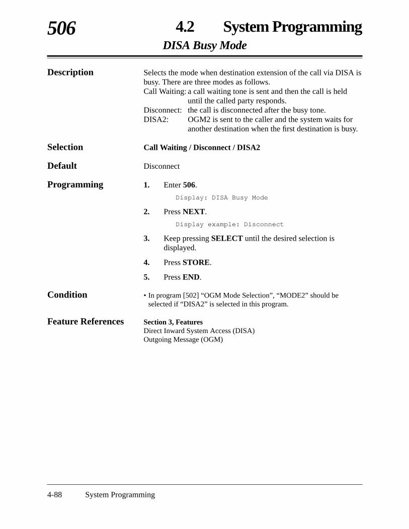
4-88 System Programming
4.2 System ProgrammingDISA Busy Mode
506
Description Selects the mode when destination extension of the call via DISA isbusy. There are three modes as follows.Call Waiting: a call waiting tone is sent and then the call is held
until the called party responds.Disconnect: the call is disconnected after the busy tone.DISA2: OGM2 is sent to the caller and the system waits for
another destination when the first destination is busy.
Selection Call Waiting / Disconnect / DISA2
Default Disconnect
Programming 1. Enter 506.
Display: DISA Busy Mode
2. Press NEXT.
Display example: Disconnect
3. Keep pressing SELECT until the desired selection isdisplayed.
4. Press STORE.
5. Press END.
Condition • In program [502] “OGM Mode Selection”, “MODE2” should beselected if “DISA2” is selected in this program.
Feature References Section 3, FeaturesDirect Inward System Access (DISA)Outgoing Message (OGM)

4.2 System ProgrammingDISA Intercept Mode
507
System Programming 4-89
Description Intercept Routing provides an automatic re-direction of DISA callswhich cannot or have not been answered within the programmedtime. This program is used to select whether the call isdisconnected or re-directed.Intercept: the call is directed to the extensions assigned in
programs [408]–[410].Disconnect: the call is disconnected.
Selection Disconnect / Intercept
Default Intercept
Programming 1. Enter 507.
Display: DISA IRNA Mode
2. Press NEXT.
Display example: Intercept
3. Keep pressing SELECT until the desired selection isdisplayed.
4. Press STORE.
5. Press END.
Conditions None
Feature References Section 3, FeaturesDirect Inward System Access (DISA)Intercept RoutingVoice Mail Integration for KX-TVS50Voice Mail Integration for KX-TVS75/KX-TVS100

4-90 System Programming
4.2 System ProgrammingDISA Ringing Time before Intercept
508
Description Selects the time for the Intercept Routing — No Answer (IRNA)feature. If a DISA call is not answered within the programmedtime, the call will be redirected to the programmed extension.
Selection 10 sec / 20 sec / 30 sec / 40 sec / 60 sec / 120 sec (seconds)
Default 20 sec
Programming 1. Enter 508.
Display: DISA Befor IRNA
2. Press NEXT.
Display example: Time: 20sec
3. Keep pressing SELECT until the desired selection isdisplayed.
4. Press STORE.
5. Press END.
Condition • Programs [408]–[410] “Flexible Ringing Assignment —Day/Night/Lunch” are used to program the destination of InterceptRouting in the day, night and lunch modes.
Feature References Section 3, FeaturesDirect Inward System Access (DISA)Intercept Routing
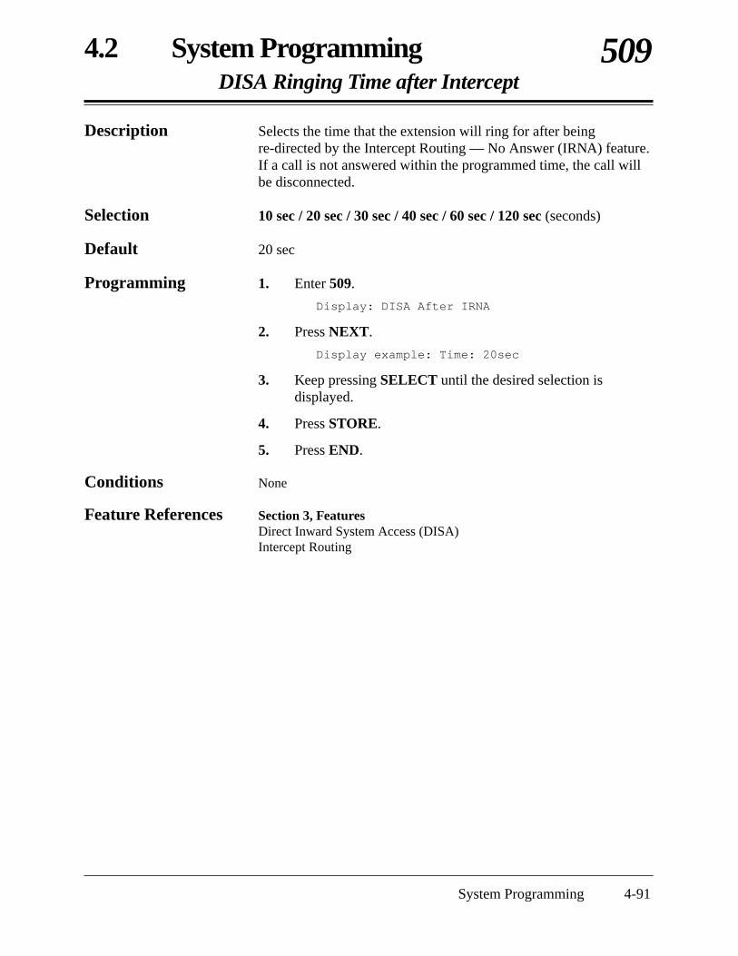
4.2 System ProgrammingDISA Ringing Time after Intercept
509
System Programming 4-91
Description Selects the time that the extension will ring for after beingre-directed by the Intercept Routing — No Answer (IRNA) feature.If a call is not answered within the programmed time, the call willbe disconnected.
Selection 10 sec / 20 sec / 30 sec / 40 sec / 60 sec / 120 sec (seconds)
Default 20 sec
Programming 1. Enter 509.
Display: DISA After IRNA
2. Press NEXT.
Display example: Time: 20sec
3. Keep pressing SELECT until the desired selection isdisplayed.
4. Press STORE.
5. Press END.
Conditions None
Feature References Section 3, FeaturesDirect Inward System Access (DISA)Intercept Routing

4-92 System Programming
4.2 System ProgrammingDISA No Dial Mode
510
Description Selects the mode when nothing is dialed after the OGM or a beepafter a programmed length of time for the DISA1 and DISA2modes. There are two modes as follows.Intercept: the call is directed to the extensions assigned in
programs [408]–[410] for the time programmed in[509] “DISA Ringing Time After Intercept”.
Disconnect: the call is disconnected.
Selection • DISA1 / DISA2• Intercept / Disconnect
Default DISA1 and DISA2 — Intercept
Programming 1. Enter 510.
Display: No Dial Mode
2. Press NEXT.
Display example: DISA1:Disconnect
3. Keep pressing SELECT until the desired selection isdisplayed.
4. Press STORE.
5. Press NEXT or PREV to program the other parameter.
6. Repeat steps 3 through 5.
7. Press END.
Conditions None
Feature References Section 3, FeaturesDirect Inward System Access (DISA)Intercept Routing

4.2 System ProgrammingDISA Security Type
511
System Programming 4-93
Description Assigns the security mode for outside calls from a DISA (DirectInward System Access) caller. There are three modes: NoneSecurity, Trunk Security (outside (CO) line security), and AllSecurity. None Security mode allows the caller to access an outside(CO) line without dialing a DISA security code. Trunk Securitymode requires the caller to enter a DISA security code beforemaking an outside call. All Security mode requires the caller toenter a DISA security code before making either an outside call oran intercom call.
Selection None Security / Trunk Security / All Security
Default Trunk Security
Programming 1. Enter 511.
Display: Security Type
2. Press NEXT.
Display example: Trunk Security
3. Keep pressing SELECT until the desired selection isdisplayed.
4. Press STORE.
5. Press END.
Condition • Program [512] “DISA Security Codes” is used to program the DISASecurity Codes.
Feature Reference Section 3, FeaturesDirect Inward System Access (DISA)

4-94 System Programming
4.2 System ProgrammingDISA Security Codes
512
Description Assigns the DISA (Direct Inward System Access) Security Codes.
Selection • Code number : 1 – 4• DISA security code: 4 digits
Default All codes — Not stored
Programming 1. Enter 512.
Display: Security Code
2. Press NEXT.
Display: CODE-01:Not Stored
3. Enter a code number.
Display example: CODE-01: 1234
4. Enter a DISA security code.
To change the current entry, press CLEAR and enter the new code.
5. Press STORE.
6. To program another code, press NEXT or PREV, orSELECT and enter the desired code number.
7. Repeat steps 4 through 6.
8. Press END.
Conditions • This setting is required if All Security mode or Trunk (outside (CO)line) Security mode is selected in program [511] “DISA Security Type”.
• There are four programmable security codes. Each code should bedifferent and composed of four numerical digits, 0 – 9.
• The used security code numbers (not security codes) are printed on theSMDR.
Feature Reference Section 3, FeaturesDirect Inward System Access (DISA)

4.2 System ProgrammingCyclic Tone Detection
513
System Programming 4-95
Description Selects the number of times that the system detects the cyclic tone.The system regards a call as completed after detecting the cyclictone the programmed number of times.
Selection Disable (will not detect) / 2 Times / 3 Times / 4 Times
Default 4 Times
Programming 1. Enter 513.
Display: Tone Detection
2. Press NEXT.
Display example: 4 Times
3. Keep pressing SELECT until the desired selection isdisplayed.
4. Press STORE.
5. Press END.
Condition • An optional OGM/FAX Detection card is necessary.
Feature Reference Section 3, FeaturesDirect Inward System Access (DISA)

4-96 System Programming
4.2 System ProgrammingFAX Tone Detection
514
Description Selects the number of times the CNG tone (FAX tone) is detected.An incoming fax call via the Direct Inward System Access (DISA)feature is detected by the system after receiving the CNG tone theassigned number of times.
Selection 1 Time / 2 Times
Default 1 Time
Programming 1. Enter 514.
Display: FAX Detection
2. Press NEXT.
Display example: 1 Time
3. Keep pressing SELECT until the desired selection isdisplayed.
4. Press STORE.
5. Press END.
Condition • An optional OGM/FAX Detection card is necessary.
Feature References Section 3, FeaturesDirect Inward System Access (DISA)Facsimile Detection
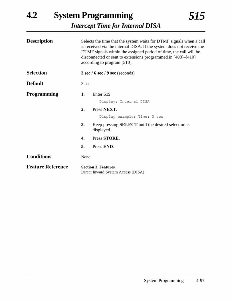
4.2 System ProgrammingIntercept Time for Internal DISA
515
System Programming 4-97
Description Selects the time that the system waits for DTMF signals when a callis received via the internal DISA. If the system does not receive theDTMF signals within the assigned period of time, the call will bedisconnected or sent to extensions programmed in [408]–[410]according to program [510].
Selection 3 sec / 6 sec / 9 sec (seconds)
Default 3 sec
Programming 1. Enter 515.
Display: Internal DISA
2. Press NEXT.
Display example: Time: 3 sec
3. Keep pressing SELECT until the desired selection isdisplayed.
4. Press STORE.
5. Press END.
Conditions None
Feature Reference Section 3, FeaturesDirect Inward System Access (DISA)
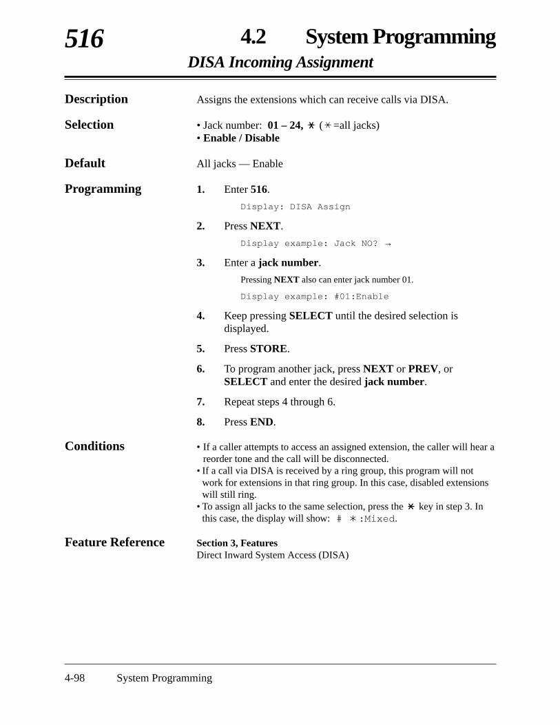
4-98 System Programming
4.2 System ProgrammingDISA Incoming Assignment
516
Description Assigns the extensions which can receive calls via DISA.
Selection • Jack number: 01 – 24, ( =all jacks)• Enable / Disable
Default All jacks — Enable
Programming 1. Enter 516.
Display: DISA Assign
2. Press NEXT.
Display example: Jack NO? →
3. Enter a jack number.
Pressing NEXT also can enter jack number 01.
Display example: #01:Enable
4. Keep pressing SELECT until the desired selection isdisplayed.
5. Press STORE.
6. To program another jack, press NEXT or PREV, orSELECT and enter the desired jack number.
7. Repeat steps 4 through 6.
8. Press END.
Conditions • If a caller attempts to access an assigned extension, the caller will hear areorder tone and the call will be disconnected.
• If a call via DISA is received by a ring group, this program will notwork for extensions in that ring group. In this case, disabled extensionswill still ring.
• To assign all jacks to the same selection, press the key in step 3. Inthis case, the display will show: # :Mixed.
Feature Reference Section 3, FeaturesDirect Inward System Access (DISA)

4.2 System ProgrammingDISA AA Wait Time
517
System Programming 4-99
Description Selects the time that the system waits for a second digit entry. If thetimer expires, the system will assume that the first digit is a DISAbuilt-in auto attendant number (AA number) if an AA number isassigned in program [501] “DISA Built-in Auto Attendant”. For example, if a number is not dialed within the programmed timeafter dialing 1, the system will assume that “1” is an AA number.
Selection 1 sec / 2 sec / 3 sec / 4 sec / 5 sec (seconds)
Default 2 sec
Programming 1. Enter 517.
Display: DISA AA Time
2. Press NEXT.
Display example: Time: 2 sec
3. Keep pressing SELECT until the desired selection isdisplayed.
4. Press STORE.
5. Press END.
Condition • The AA wait timer will only work when “1” or “8” is dialed.
Feature Reference Section 3, FeaturesDirect Inward System Access (DISA)
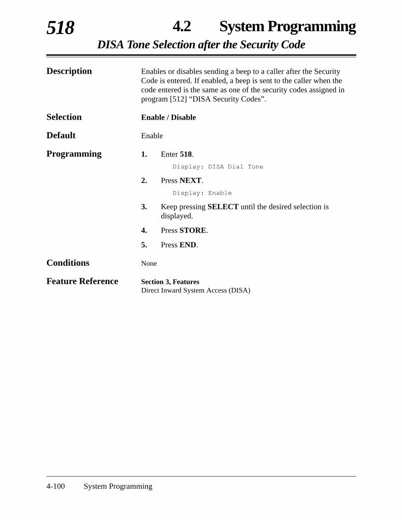
4-100 System Programming
4.2 System ProgrammingDISA Tone Selection after the Security Code
518
Description Enables or disables sending a beep to a caller after the SecurityCode is entered. If enabled, a beep is sent to the caller when thecode entered is the same as one of the security codes assigned inprogram [512] “DISA Security Codes”.
Selection Enable / Disable
Default Enable
Programming 1. Enter 518.
Display: DISA Dial Tone
2. Press NEXT.
Display: Enable
3. Keep pressing SELECT until the desired selection isdisplayed.
4. Press STORE.
5. Press END.
Conditions None
Feature Reference Section 3, FeaturesDirect Inward System Access (DISA)

4.2 System ProgrammingExtension Group Assignment
600
System Programming 4-101
Description Assigns an extension group for each extension. Extension groupsare used for Group Call Pickup, Station Hunting, Paging – Groupand Ring Group.
Selection • Jack number: 01 – 24, ( = all jacks)• Extension group number (EXT GRP): 1 – 8
Default All jacks — EXT GRP-1
Programming 1. Enter 600.
Display: Extension Group
2. Press NEXT.
Display: Jack NO? →
3. Enter a jack number.
Pressing NEXT also can enter jack number 01.
Display example: #01:EXT GRP-1
4. Enter the extension group number.
To change the current entry, enter the new extension group number.
5. Press STORE.
6. To program another jack, press NEXT or PREV, orSELECT and enter the desired jack number.
7. Repeat steps 4 through 6.
8. Press END.
Conditions • There is a maximum of eight extension groups. Each extension can onlybelong to one group.
• To assign all jacks to the same extension group, press the key instep 3. In this case, the display will show: # :Mixed.
Feature ReferencesSection 3, FeaturesCall Pickup, Group Paging – GroupExtension Group Ring GroupStation Hunting

4-102 System Programming
4.2 System ProgrammingTRS – Class of Service (COS) Assignment — Day/Night/Lunch
601–603
Description Programs Toll Restriction (TRS) – Class of Service (COS) for eachextension.
Selection • Jack number: 01 – 24, ( = all jacks)• COS-1 / COS-2 / COS-3 / COS-4 / COS-5
Default All jacks — COS-1
Programming 1. Enter a program address (601 for day, 602 for night, or603 for lunch).
Display example: Day Toll Restr
2. Press NEXT.
Display: Jack NO? →
3. Enter a jack number.
Pressing NEXT also can enter jack number 01.
Display example: #01: COS-1
4. Keep pressing SELECT until the desired selection isdisplayed.
5. Press STORE.
6. To program another jack, press NEXT or PREV, orSELECT and enter the desired jack number.
7. Repeat steps 4 through 6.
8. Press END.
Condition • To assign all jacks to the same COS, press the key in step 3. In thiscase, the display will show: # :Mixed.
Feature Reference Section 3, FeaturesToll Restriction

4.2 System ProgrammingExtension Name Setting
604
System Programming 4-103
Description Assigns names to the extensions.
Selection • Jack number: 01 – 24• Name: 10 characters (max.)
Default All jacks – Not stored
Programming 1. Enter 604.
Display: Extension Name
2. Press NEXT.
Display: Jack NO? →
3. Enter a jack number.
Pressing NEXT also can enter jack number 01.
Display: #01:
4. Enter a name.
For entering characters, see Section 4.1.3 “Entering Characters”.To delete the current entry, press CLEAR.To change the current entry, press CLEAR and enter the new name.
5. Press STORE.
6. To program another jack, press NEXT or PREV, orSELECT and enter the desired jack number.
7. Repeat steps 4 through 6.
8. Press END.
Conditions • There is a maximum of 24 names. Each name has a maximum of10 characters.
• Program [009] “Extension Number Assignment” is used to assign theextension numbers.
Feature References Section 3, FeaturesDisplay, Call InformationDisplay, in IdleIntercom Calling

4-104 System Programming
4.2 System ProgrammingAccount Code Entry Mode
605
Description Selects the account code input mode for each extension jack. Thereare four account code modes: Option, Forced, Verify-All andVerify-Toll.Option mode: The user can enter any account code, if
needed.Forced mode: The user must always enter an account code.
The code can be any number.Verify – All mode: The user must always enter a pre-assigned
account code to make an outside call.Verify – Toll mode: The user can enter an assigned account code
to override toll restriction. The toll restrictionCOS numbers 3 through 5 will be changedtemporarily to the COS number 2. (The COSnumbers 1 and 2 will not be changed.)
Selection • Jack number: 01 – 24, ( = all jacks)• Option / Forced / Verify – All / Verify – Toll
Default All jacks – Option
Programming 1. Enter 605.
Display: Call Accounting
2. Press NEXT.
Display: Jack NO? →
3. Enter a jack number.
Pressing NEXT also can enter jack number 01.
Display: #01:Option
4. Keep pressing SELECT until the desired selection isdisplayed.
5. Press STORE.
6. To program another jack, press NEXT or PREV, orSELECT and enter the desired jack number.
7. Repeat steps 4 through 6.
8. Press END.
4.2 System ProgrammingAccount Code Entry Mode (contd.)
605
System Programming 4-105
Conditions • To assign all jacks to the same selection, press the key in step 3. Inthis case, the display will show: # :Mixed.
• Program [310] “Account Codes” is used to define the Account Codes forthe Verify modes.
• Programs [601]–[603] “TRS – Class of Service (COS) Assignment —Day/Night/Lunch” is used to assign a Class of Service to each extension.
Feature References Section 3, FeaturesAccount Code EntryToll Restriction Override by Account Codes

4-106 System Programming
4.2 System ProgrammingCall Transfer to an Outside (CO) Line
606
Description Enables or disables performing the Call Transfer to an Outside(CO) Line feature.
Selection • Jack number: 01 – 24, ( = all jacks)• Enable / Disable
Default Disable
Programming 1. Enter 606.
Display: Transfer to CO
2. Press NEXT.
Display: Jack NO? →
3. Enter a jack number.
Pressing NEXT also can enter jack number 01.
Display example: #01:Disable
4. Keep pressing SELECT until the desired selection isdisplayed.
5. Press STORE.
6. To program another jack, press NEXT or PREV, orSELECT and enter the desired jack number.
7. Repeat steps 4 through 6.
8. Press END.
Condition • To assign all jacks to the same selection, press the key in step 3. Inthis case, the display will show: # :Mixed.
Feature Reference Section 3, FeaturesCall Transfer, Screened – to an Outside (CO) Line

4.2 System ProgrammingCall Forwarding to an Outside (CO) Line
607
System Programming 4-107
Description Enables or disables performing the Call Forwarding to an Outside(CO) Line feature.
Selection • Jack number: 01 – 24, ( = all jacks)• Disable / Enable
Default All jacks – Disable
Programming 1. Enter 607.
Display: CO Forward
2. Press NEXT.
Display: Jack NO? →
3. Enter a jack number.
Pressing NEXT also can enter jack number 01.
Display example: #01:Disable
4. Keep pressing SELECT until the desired selection isdisplayed.
5. Press STORE.
6. To program another jack, press NEXT or PREV, orSELECT and enter the desired jack number.
7. Repeat steps 4 through 6.
8. Press END.
Condition • To assign all jacks to the same selection, press the key in step 3. Inthis case, the display will show: # :Mixed.
Feature Reference Section 3, FeaturesCall Forwarding – to an Outside (CO) Line

4-108 System Programming
4.2 System ProgrammingExecutive Busy Override
608
Description Enables or disables performing Executive Busy Override –Extension/Outside (CO) Line. Executive Busy Override allows auser to interrupt an established call.
Selection • Jack number: 01 – 24, ( = all jacks)• Disable / Enable
Default All jacks – Disable
Programming 1. Enter 608.
Display: Busy Override
2. Press NEXT.
Display: Jack NO? →
3. Enter a jack number.
Pressing NEXT also can enter jack number 01.
Display example: #01:Disable
4. Keep pressing SELECT until the desired selection isdisplayed.
5. Press STORE.
6. To program another jack, press NEXT or PREV, orSELECT and enter the desired jack number.
7. Repeat steps 4 through 6.
8. Press END.
Condition • To assign all jacks to the same selection, press the key in step 3. Inthis case, the display will show: # :Mixed.
Feature References Section 3, FeaturesExecutive Busy Override – ExtensionExecutive Busy Override – Outside (CO) Line

4.2 System ProgrammingDo Not Disturb Override
609
System Programming 4-109
Description Enables or disables performing the Do Not Disturb (DND)Override feature.
Selection • Jack number: 01 – 24, ( = all jacks)• Disable / Enable
Default All jacks – Disable
Programming 1. Enter 609.
Display: DND Override
2. Press NEXT.
Display: Jack NO? →
3. Enter a jack number.
Pressing NEXT also can enter jack number 01.
Display example: #01:Disable
4. Keep pressing SELECT until the desired selection isdisplayed.
5. Press STORE.
6. To program another jack, press NEXT or PREV, orSELECT and enter the desired jack number.
7. Repeat steps 4 through 6.
8. Press END.
Condition • To assign all jacks to the same selection, press the key in step 3. Inthis case, the display will show: # :Mixed.
Feature Reference Section 3, FeaturesDo Not Disturb (DND) Override

4-110 System Programming
4.2 System ProgrammingParalleled Telephone Connection
610
Description A Paralleled Telephone Connection allows a single line telephoneto be connected to the same jack as a proprietary telephone. Thisprogram assigns which jacks can perform the paralleled telephoneconnection feature.
Selection • Jack number: 01 – 24, ( = all jacks)• Disable / Enable
Default All jacks – Disable
Programming 1. Enter 610.
Display: Parallel Connect
2. Press NEXT.
Display: Jack NO? →
3. Enter a jack number.
Pressing NEXT also can enter jack number 01.
Display example: #01:Disable
4. Keep pressing SELECT until the desired selection isdisplayed.
5. Press STORE.
6. To program another jack, press NEXT or PREV, orSELECT and enter the desired jack number.
7. Repeat steps 4 through 6.
8. Press END.
Condition • To assign all jacks to the same selection, press the key in step 3. Inthis case, the display will show: # :Mixed.
Feature Reference Section 3, FeaturesParalleled Telephone

4.2 System ProgrammingTAM (Telephone Answering Machine) Extension
611
System Programming 4-111
Description Assigns the jacks that can accept a TAM connection. When a jackis TAM-enabled, the “Call Retrieving from a TAM” featurebecomes available.
Selection • Jack number: 01 – 24, ( = all jacks)• Disable / Enable
Default All jacks – Disable
Programming 1. Enter 611.
Display: TAM Extension
2. Press NEXT.
Display: Jack NO? →
3. Enter a jack number.
Pressing NEXT also can enter jack number 01.
Display example: #01:Disable
4. Keep pressing SELECT until the desired selection isdisplayed.
5. Press STORE.
6. To program another jack, press NEXT or PREV, orSELECT and enter the desired jack number.
7. Repeat steps 4 through 6.
8. Press END.
Condition • To assign all jacks to the same selection, press the key in step 3. Inthis case, the display will show: # :Mixed.
Feature Reference Section 3, FeaturesCall Retrieving from a TAM (Telephone Answering Machine)

4-112 System Programming
4.2 System ProgrammingRoom Monitor Assignment
612
Description Assigns which extensions can be monitored by another telephone.
Selection • Jack number: 01 – 24, ( = all jacks)• Disable / Enable
Default All jacks – Disable
Programming 1. Enter 612.
Display: Room Monitor
2. Press NEXT.
Display: Jack NO? →
3. Enter a jack number.
Pressing NEXT also can enter jack number 01.
Display example: #01:Disable
4. Keep pressing SELECT until the desired selection isdisplayed.
5. Press STORE.
6. To program another jack, press NEXT or PREV, orSELECT and enter the desired jack number.
7. Repeat steps 4 through 6.
8. Press END.
Conditions • To assign all jacks to the same selection, press the key in step 3. Inthis case, the display will show: # :Mixed.
• The jacks which are assigned to “DISABLE” cannot accept featurenumber “7351#” for the room monitor feature.
Feature Reference Section 3, FeaturesRoom Monitor

4.2 System ProgrammingWireless PT Port Assignment
617
System Programming 4-113
Description Used to identify whether the Panasonic Wireless Phone (e.g.KX-T7880 or KX-T7885) is connected to an extension jack or not.
Selection • Jack number: 01 – 24, ( = all jacks)• Not Connect / Connect
Default All jacks – Not Connect
Programming 1. Enter 617.
Display: Wireless PT Port
2. Press NEXT.
Display: Jack NO? →
3. Enter a jack number.
Pressing NEXT also can enter jack number 01.
Display example: #01:Not Connect
4. Keep pressing SELECT until the desired selection isdisplayed.
5. Press STORE.
6. To program another jack, press NEXT or PREV, orSELECT and enter the desired jack number.
7. Repeat steps 4 through 6.
8. Press END.
Conditions • To assign all jacks to the same selection, press the key in step 3. In this case, the display will show: # :Mixed.
• If “Connect” is not assigned for the jack which is connected thePanasonic Wireless Phone, the wireless phone may work incorrectly.

4-114 System Programming
4.2 System ProgrammingDoorphone Ringing Assignment — Day/Night/Lunch
700–702
Description These programs assign which extensions will ring when adoorphone call is received in the day, night and lunch modes.
Selection • Doorphone number: 1 – 4, ( = all doorphones)• Jack number: 01 – 24, ( = all jacks)• Enable / Disable
Default All doorphones – all jacks – Enable — Day/Night/Lunch
Programming 1. Enter a program address (700 for day, 701 for night or 702for lunch).
Display example: Day Door Phone
2. Press NEXT.
Display: Door NO? →
3. Enter a doorphone number.
Pressing NEXT also can enter doorphone number 1.
Display example: DP-1:#01:Enable
4. Keep pressing until the desired jack number is displayedor enter a jack number after pressing the # key.
5. Keep pressing SELECT until the desired selection isdisplayed.
6. Press STORE.
7. To program another jack, press or , or # and thedesired jack number.
8. Repeat steps 5 through 7.
9. To program another doorphone, press NEXT or PREV, orSELECT and enter the desired doorphone number.
10. Repeat steps 4 through 9.
11. Press END.
Conditions • To assign all doorphones and all jacks to the same selection, press thekey in steps 3 and 4.
In this case, the display will show: DP- :# :Mixed.• Four doorphones can be installed to the system.
Feature References Section 3, FeaturesDoorphone CallTime (Day/Night/Lunch) Service

System Programming 4-115
4.2 System ProgrammingDoor Opener Assignment — Day/Night/Lunch
703–705
Description These programs assign which extensions can open a door in theday, night and lunch modes.
Selection • Door opener number: 1 – 4, ( = all door openers)• Jack number: 01 – 24, ( = all jacks)• Enable / Disable
Default All door openers – all jacks – Enable
Programming 1. Enter a program address (703 for day, 704 for night or705 for lunch).
Display example: Day Door-Open
2. Press NEXT.
Display: Door NO? →
3. Enter a door opener number.
Pressing NEXT also can enter doorphone number 1.
Display example: DP-1:#01:Enable
4. Keep pressing until the desired jack number is displayedor enter a jack number after pressing the # key.
5. Keep pressing SELECT until the desired selection isdisplayed.
6. Press STORE.
7. To program another jack number, press or , or # andthe desired jack number.
8. Repeat steps 5 through 7.
9. To program another door opener, press NEXT or PREV, orSELECT and enter the desired door opener number.
10. Repeat steps 4 through 9.
11. Press END.
Conditions • To assign all door openers and all jacks to the same selection, press thekey in steps 3 and 4.
In this case, the display will show: DP- :# :Mixed.• Four door openers can be installed per system.
Feature References Section 3, FeaturesDoor OpenerTime (Day/Night/Lunch) Service

4-116 System Programming
4.2 System ProgrammingDoorphone Ringing/Tone Pattern Selection
706
Selection • Doorphone number: 1 – 4, ( = all doorphones)• Single / Double / Triple / S-Double
Default All doorphones — Triple
Programming 1. Enter 706.
Display: Door Ring Tone
2. Press NEXT.
Display: Door NO? →
3. Enter a doorphone number.
Pressing NEXT also can enter doorphone number 1.
Display example: DP-1:Triple
4. Keep pressing SELECT until the desired selection isdisplayed.
5. Press STORE.
6. To program another doorphone, press NEXT or PREV, orSELECT and enter the desired doorphone number.
7. Repeat steps 4 through 6.
8. Press END.
Conditions • To assign all doorphones to the same selection, press the key instep 3. In this case, the display will show: DP- :Mixed.
• PT users will hear the assigned pattern tone instead of ringing.• The programs [115] “Extension Ringing Pattern Selection” and [423]
“Outside (CO) Line Ringing Pattern Selection” should be consideredwhen assigning this program.
Feature Reference Section 3, FeaturesDoorphone Call
Description Assigns an incoming doorphone call ringing pattern for eachdoorphone. There are four types of patterns as follows.
1 s
Single:
Double:
Triple:
S-Double:

4.2 System ProgrammingDoorphone Access Tone Selection
707
System Programming 4-117
Description Enables or disables sending a doorphone access tone to a monitoreddoorphone. If enabled, the access tone is heard from the doorphonewhen monitoring starts.
Selection • Doorphone number: 1 – 4, ( = all doorphones)• Enable / Disable
Default All doorphones — Enable
Programming 1. Enter 707.
Display: Door Ack-Tone
2. Press NEXT.
Display: Door NO? →
3. Enter a doorphone number.
Pressing NEXT also can enter doorphone number 1.
Display example: DP-1:Enable
4. Keep pressing SELECT until the desired selection isdisplayed.
5. Press STORE.
6. To program another doorphone, press NEXT or PREV, orSELECT and enter the desired doorphone number.
7. Repeat steps 4 through 6.
8. Press END.
Condition • To assign all doorphones to the same selection, press the key instep 3. In this case, the display will show: DP- :Mixed.
Feature References Section 3, FeaturesDoorphone CallRoom Monitor

4-118 System Programming
4.2 System ProgrammingDoorphone Ringing Time
708
Description Selects the doorphone ringing time.
Selection • Doorphone number: 1 – 4, ( = all doorphones)• 15 sec / 30 sec (seconds)
Default All doorphones — 15 sec
Programming 1. Enter 708.
Display: Doorphone R-Time
2. Press NEXT.
Display: Door NO? →
3. Enter a doorphone number.
Pressing NEXT also can enter doorphone number 1.
Display example: DP-1:15 sec
4. Keep pressing SELECT until the desired selection isdisplayed.
5. Press STORE.
6. To program another doorphone, press NEXT or PREV, orSELECT and enter the desired doorphone number.
7. Repeat steps 4 through 6.
8. Press END.
Condition • To assign all doorphones to the same selection, press the key instep 3. In this case, the display will show: DP- :Mixed.
Feature Reference Section 3, FeaturesDoorphone Call

4.2 System ProgrammingDoor Opener Time
709
System Programming 4-119
Description Selects the door opener time. The door is unlocked for the assignedperiod of time.
Selection • Door Opener number: 1 – 4, ( = all door openers)• 1 sec / 2 sec / 3 sec / 4 sec / 5 sec / 6 sec / 7 sec / 8 sec (seconds)
Default All door openers — 5 sec
Programming 1. Enter 709.
Display: Door-Opner Time
2. Press NEXT.
Display: Door NO? →
3. Enter a door opener number.
Pressing NEXT also can enter doorphone number 1.
Display example: DP-1: 5 sec
4. Keep pressing SELECT until the desired selection isdisplayed.
5. Press STORE.
6. To program another door opener, press NEXT or PREV, orSELECT and enter the desired door opener number.
7. Repeat steps 4 through 6.
8. Press END.
Condition • To assign all door openers to the same selection, press the key instep 3. In this case, the display will show: DP- :Mixed.
Feature Reference Section 3, FeaturesDoor Opener

4-120 System Programming
4.2 System ProgrammingSMDR RS-232C Communication Parameters
800
Description Assigns the communication parameters for the Serial Interface(RS-232C).
New line code: Selects the code for the printer or personal computer. If the printeror personal computer automatically feeds lines with a carriagereturn, select “CR”. If not, select “CR+LF”.
Baud rate: The baud rate code indicates the data transmission speed from thesystem to the printer or personal computer.
Word length: The word length code indicates how many bits compose a character. Parity: The parity code indicates what type of parity is used to detect an
error in the string of bits composing a character. Make the selectiondepending on the requirements of the printer or personal computer.
Stop bit: The stop bit code indicates the end of a bit string which composes acharacter. Select a value depending on the requirements of theprinter or personal computer.
Selection • New line code: CR+LF / CR(CR=Carriage Return, LF=Line Feed)
• Baud rate (baud): 150 / 300 / 600 / 1200 / 2400 / 4800 / 9600• Word length (bits): 7 / 8• Parity bit: None / Mark / Space / Even / Odd• Stop bit length (bits): 1 / 2
Default New line code = CR+LF; Baud rate = 9600; Word length = 8;Parity bit = Mark; Stop bit = 1
Programming 1. Enter 800.
Display example: RS232C Parameter
2. Press NEXT to program the new line code.
Display example: NL-Code:CR+LF
3. Keep pressing SELECT until the desired selection isdisplayed.
4. Press STORE.
5. Press NEXT to program the baud rate.
Display example: Baud Rate:9600B

4.2 System ProgrammingSMDR RS-232C Communication Parameters (contd.)
800
System Programming 4-121
6. Keep pressing SELECT until the desired selection isdisplayed.
7. Press STORE.
8. Press NEXT to program the word length.
Display example: Word Length:8bit
9. Keep pressing SELECT until the desired selection isdisplayed.
10. Press STORE.
11. Press NEXT to program the parity bit.
Display example: Parity:Mark
12. Keep pressing SELECT until the desired selection isdisplayed.
13. Press STORE.
14. Press NEXT to program the stop bit.
Display example: Stop Bit:1bit
15. Keep pressing SELECT until the desired selection isdisplayed.
16. Press STORE.
17. Press END.
Condition • The following combinations are invalid.
Feature Reference Section 3, FeaturesStation Message Detail Recording (SMDR)
Parity
Mark
Space
Space
8
8
8
2
1
2
Word Length Stop Bit

4-122 System Programming
4.2 System ProgrammingSMDR Parameter
801
Description Used to match the SMDR output to the paper size being used in theprinter. The page length determines the number of lines per page.The skip perforation determines the number of lines to be skippedat the end of every page.
Selection • Page length (lines): 4 – 99• Skip perforation (lines): 0 – 95
Default Page length – 66; Skip perforation – 0
Programming 1. Enter 801.
Display: SMDR Parameter
2. Press NEXT to program the page length.
Display example: Page Length:66
3. Enter the page length.
To change the current entry, press CLEAR and enter the new pagelength.
4. Press STORE.
5. Press NEXT to program the skip perforation.
Display example: Skip Perf: 0
6. Enter the skip perforation.
To change the current entry, press CLEAR and enter the new skipperforation.
7. Press STORE.
8. Press END.
Conditions • The page length should be at least four lines longer than the skipperforation length.
• The title is placed on the first three lines of every page.• The programmed format becomes valid only if the Serial Interface
(RS-232C) cable is connected. If a printer is already connected,disconnect it and connect again. Otherwise the previous format will beused.
Feature Reference Section 3, FeaturesStation Message Detail Recording (SMDR)

4.2 System ProgrammingIncoming/Outgoing Call Selection for Printing
802
System Programming 4-123
Description Used to determine which calls will produce an SMDR printout.
Selection • Outgoing calls: On (all calls) / Off (no printing) / Toll (printingtoll calls only)
• Incoming calls: On (all calls) / Off (no printing)
Default Outgoing calls – On; Incoming calls – On
Programming 1. Enter 802.
Display: Call Printing
2. Press NEXT to program outgoing calls.
Display: Outgoing:On
3. Keep pressing SELECT until the desired selection isdisplayed.
4. Press STORE.
5. Press NEXT to program incoming calls.
Display: Incoming:On
6. Keep pressing SELECT until the desired selection isdisplayed.
7. Press STORE.
8. Press END.
Conditions • A printer must be connected to the Serial Interface (RS-232C) portprovided on the system.
• When “Toll” is selected, only calls which are checked in programs[302]–[305] “Toll Restriction — Class 2 – 5 Denied Codes” and areallowed, are printed out.
Feature Reference Section 3, FeaturesStation Message Detail Recording (SMDR)

4-124 System Programming
4.2 System ProgrammingSecret Speed Dialing/One-Touch Dialing Printing
803
Description Enables or disables printing out the secret dial numbers stored inspeed dialing and one-touch dialing on the SMDR.
Selection • No printing / Printing
Default No printing
Programming 1. Enter 803.
Display: Secret Printing
2. Press NEXT.
Display example: No Printing
3. Keep pressing SELECT until the desired selection isdisplayed.
4. Press STORE.
5. Press END.
Conditions None
Feature References Section 3, FeaturesSecret DialingStation Message Detail Recording (SMDR)

4.2 System ProgrammingSystem Data Dump
804
System Programming 4-125
Description Starts or stops printing the assigned data. All or a specific area ofcurrent programmed data is printed out. The areas are as follows.All Para: All dataSystem Para: All data except the following programs.CO Para: Programmed data of [400]–[403], [405]–[423] and
[900].Ext Para: Programmed data of [102], [516], [600]–[620], and
[904] and [905] if a proprietary telephone isconnected. The assigned data on the PF(Programmable Feature) buttons and CO buttons arealso printed out.Programmed data of [102], [516] and [600]–[612] ifa single line telephone is connected. The storedPersonal Speed Dialing numbers are also printedout.
DSS Para: Data assigned to DSS buttons and PF buttons on theDSS Consoles.
Speed Dial: Programmed data of [001]Stop Output: Stops printing.
Selection All Para / System Para / CO Para + outside (CO) line number:1 – 6, ( = all outside (CO) lines) / Ext Para + jack number: 01 – 24, ( = all jacks) / DSS Para + DSS Console number: 1 or 2, ( = all DSSConsoles) / Speed Dial / Stop Output
Default Not applicable.
Programming 1. Enter 804.
Display: System Data Dump
2. Press NEXT.
Display: Menu:All Para
3. Keep pressing SELECT until the desired selection isdisplayed.
4. Press STORE.
5. If CO Para, Ext Para or DSS Para is selected, enter anoutside (CO) line, jack or DSS Console number.
6. Press STORE.
7. Press END.
4-126 System Programming
4.2 System ProgrammingSystem Data Dump (contd.)
804
Condition • A printer must be connected to the Serial Interface (RS-232C) portprovided on the system.
Feature Reference Section 3, FeaturesStation Message Detail Recording (SMDR)
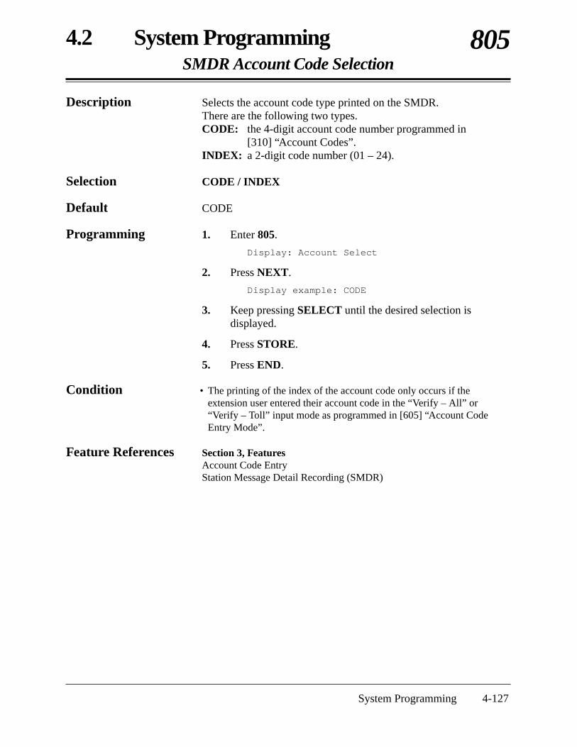
4.2 System ProgrammingSMDR Account Code Selection
805
System Programming 4-127
Description Selects the account code type printed on the SMDR. There are the following two types.CODE: the 4-digit account code number programmed in
[310] “Account Codes”.INDEX: a 2-digit code number (01 – 24).
Selection CODE / INDEX
Default CODE
Programming 1. Enter 805.
Display: Account Select
2. Press NEXT.
Display example: CODE
3. Keep pressing SELECT until the desired selection isdisplayed.
4. Press STORE.
5. Press END.
Condition • The printing of the index of the account code only occurs if theextension user entered their account code in the “Verify – All” or“Verify – Toll” input mode as programmed in [605] “Account CodeEntry Mode”.
Feature References Section 3, FeaturesAccount Code EntryStation Message Detail Recording (SMDR)

4-128 System Programming
4.2 System ProgrammingCaller ID Assignment
900
Description Enables or disables the Caller ID feature for outside (CO) lineswhich have contracted the Caller ID Service by a Central Office.
Selection • Outside (CO) line number: 1 – 6, ( = all outside (CO) lines)• Enable / Disable
Default All outside (CO) lines – Disable
Programming 1. Enter 900.
Display: CID Assign
2. Press NEXT.
Display: CO NO? →
3. Enter an outside (CO) line number.
Pressing NEXT also can enter outside (CO) line number 1.
Display example: CO 1:Disable
4. Keep pressing SELECT until the desired selection isdisplayed.
5. Press STORE.
6. To program another outside (CO) line, press NEXT orPREV, or SELECT and enter the desired outside (CO) linenumber.
7. Repeat steps 4 through 6.
8. Press END.
Conditions • To assign all outside (CO) lines to the same selection, press the keyin step 3. In this case, the display will show: CO :Mixed.
• An optional Caller ID card is required.
Feature Reference Section 3, FeaturesCaller ID

4.2 System ProgrammingCaller ID Area Code Assignment
901
System Programming 4-129
Description Assigns the required area code when using the Caller ID feature.By assigning the area code, the system records the caller’s phonenumber modified by programs [902] “Caller ID Modification forLocal Calls” and [903] “Caller ID Modification for Long DistanceCalls”.
Selection • Code number: 1 – 5• Area code: 6 digits max.
Default All codes – Not stored
Programming 1. Enter 901.
Display: CID Area Code
2. Press NEXT.
Display: CODE NO? →
3. Enter a code number.
Pressing NEXT also can enter code number 1.
Display example: CODE-01:......
4. Enter an area code.
To delete the current entry, press CLEAR.To change the current entry, press CLEAR and enter the new areacode.
5. Press STORE.
6. To program another code number, press NEXT or PREV, orSELECT and enter the desired code number.
7. Repeat steps 4 through 6.
8. Press END.
Conditions • The area code can be six digits long. Valid numbers are from 0 to 9.• An optional Caller ID card is required.
Feature References Section 3, FeaturesCall Log, IncomingCaller ID

4-130 System Programming
4.2 System ProgrammingCaller ID Modification for Local Calls
902
Description Assigns the removed digits from a received local caller’s number,and adds a number to make the final number which serves as theCaller ID number. The system records the modified caller’s numberin the incoming call log list so that the extension user can call backthe caller.Digits are removed from or added to the beginning of the receivednumber.
Selection • Number of digits to be deleted: 0 – 9 (0 = no deletion)• Number to be added: 4 digits (max.)
Default Deleted digits – 3; Added number – blank
Programming 1. Enter 902.
Display: CID Local Call
2. Press NEXT.
Display example: Del:3 Add:
3. Enter the number of digits to be deleted.
To change the current entry, press CLEAR and enter the newnumber.
4. Press to program the number to be added, if required.
5. Enter the number to be added.
To change the current entry, press CLEAR and enter the newnumber.
6. Press STORE.
7. Press END.
Conditions • The added number has a maximum of 4 digits, consisting of 0 – 9, and #.
• An optional Caller ID card is required.
Feature References Section 3, FeaturesCall Log, IncomingCaller ID

4.2 System ProgrammingCaller ID Modification for Long Distance Calls
903
System Programming 4-131
Description Assigns the removed digits from a received long distance caller’snumber, and adds a number to make the final number which servesas the Caller ID number. The system records the modified caller’snumber in the incoming call log list so that the extension user cancall back the caller.Digits are removed from or added to the beginning of the receivednumber.
Selection • Number of digits to be deleted: 0 – 9 (0 = no deletion)• Number to be added: 4 digits (max.)
Default Deleted digits – 0; Added number – 1
Programming 1. Enter 903.
Display: CID LD Call
2. Press NEXT.
Display example: Del:0 Add:1
3. Enter the number of digits to be deleted.
To change the current entry, press CLEAR and enter the newnumber.
4. Press to program the number to be added, if required.
5. Enter the number to be added.
To change the current entry, press CLEAR and enter the newnumber.
6. Press STORE.
7. Press END.
Conditions • The added number has a maximum of 4 digits, consisting of 0 – 9, and #.
• An optional Caller ID card is required.
Feature References Section 3, FeaturesCall Log, IncomingCaller ID

4-132 System Programming
4.2 System ProgrammingCaller ID Log Priority Selection
904
Description Selects the first display of an incoming outside call by the Caller IDservice.
Selection • Jack number: 01 – 24, ( = all jacks)• Number / Name
Default All jacks – Name
Programming 1. Enter 904.
Display: CID Priority
2. Press NEXT.
Display: Jack NO? →
3. Enter a jack number.
Pressing NEXT also can enter jack number 01.
Display example: #01:Name
4. Keep pressing SELECT until the desired selection isdisplayed.
5. Press STORE.
6. Press END.
Conditions • This program is available when the Caller ID service provides both thename and number. If only the number is provided, this program is notnecessary.
• To assign all jacks to the same selection, press the key in step 3. Inthis case, the display will show: CO :Mixed.
• An optional Caller ID card is required.
Feature Reference Section 3, FeaturesCaller ID

4.2 System ProgrammingCaller ID SMDR Format
906
System Programming 4-133
Description Selects whether a Caller ID number is printed out or not on theSMDR.
Selection Without CID (not printed) / With CID (printed)
Default With CID
Programming 1. Enter 906.
Display: CID SMDR Format
2. Press NEXT.
Display example: With CID
3. Keep pressing SELECT until the desired selection isdisplayed.
4. Press STORE.
5. Press END.
Conditions • Even if a name is also sent by the Caller ID service, only the number isprinted.
• An optional Caller ID card is required.
Feature References Section 3, FeaturesCaller IDStation Message Detail Recording (SMDR)
4-134 System Programming
4.2 System ProgrammingROM Version
998
Description Confirms the System ROM version.
Display example: Y501B 980430(M)
Version Date
Programming 1. Enter 998.
Display: ROM Version
2. Press NEXT.
The display shows the system ROM version.
3. Press END.
Conditions None
Feature References None

4.2 System ProgrammingSystem Data Clear
999
System Programming 4-135
Description Clears the system data which have been programmed. The systemwill re-start with the default settings.
Selection All Para / System Para / CO Para + outside (CO) line number:1 – 6, ( = all outside (CO) lines) / Ext Para + jack number: 01 – 24, ( = all jacks) / DSS Para + DSS Console number: 1 or 2, ( = all DSSConsoles) / Speed Dial
Programming 1. Enter 999.
Display: System Clear
2. Press NEXT.
Display: Menu:All Para
3. Keep pressing SELECT until the desired selection isdisplayed.
4. Press STORE.
5. If CO Para, Ext Para or DSS Para is selected, enter anoutside (CO) line, jack or DSS Console number.
6. Press STORE.
7. Press END.
Condition • Please refer to program [804] for each parameter.
Feature Reference Section 3, FeaturesSystem Data Default Set

4-136 System Programming

Section 5List
This section lists the tone, ring and default values of system programming.
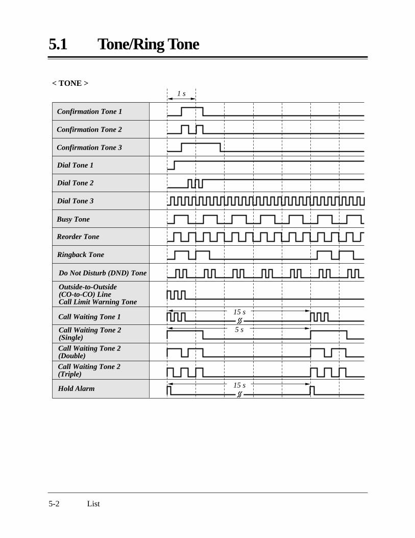
5.1 Tone/Ring Tone
5-2 List
1 s
Confirmation Tone 1
Confirmation Tone 2
Confirmation Tone 3
Dial Tone 1
Dial Tone 2
Dial Tone 3
Busy Tone
Reorder Tone
Ringback Tone
< TONE >
Do Not Disturb (DND) Tone
Outside-to-Outside (CO-to-CO) Line Call Limit Warning Tone
Call Waiting Tone 1
Call Waiting Tone 2(Single)
5 s
Call Waiting Tone 2(Double)
Call Waiting Tone 2(Triple)
Hold Alarm 15 s
15 s

5.1 Tone/Ring Tone
List 5-3
1 s
Incoming Calls (Single) /Hold Recall (Outside calls)
Callback Ringing (Camp-on Recall) / Doorphone Ringing (S-Double)
< RING TONE >
Incoming Calls (Double) /Hold Recall (Intercom calls)Incoming Calls (Triple) / Timed Reminder
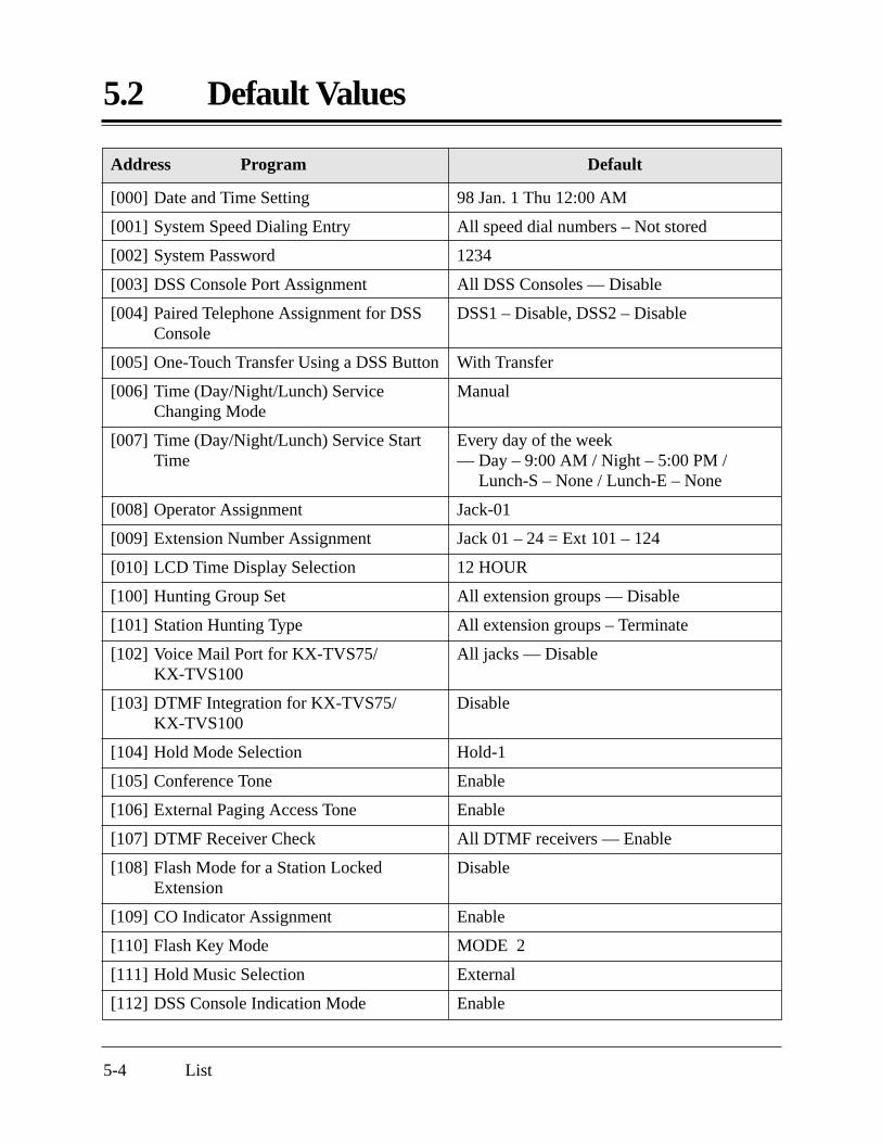
Address Program Default
5.2 Default Values
5-4 List
[000] Date and Time Setting
[001] System Speed Dialing Entry
[002] System Password
[003] DSS Console Port Assignment
[004] Paired Telephone Assignment for DSSConsole
[005] One-Touch Transfer Using a DSS Button
[006] Time (Day/Night/Lunch) ServiceChanging Mode
[007] Time (Day/Night/Lunch) Service StartTime
[008] Operator Assignment
[009] Extension Number Assignment
[010] LCD Time Display Selection
[100] Hunting Group Set
[101] Station Hunting Type
[102] Voice Mail Port for KX-TVS75/KX-TVS100
[103] DTMF Integration for KX-TVS75/KX-TVS100
[104] Hold Mode Selection
[105] Conference Tone
[106] External Paging Access Tone
[107] DTMF Receiver Check
[108] Flash Mode for a Station LockedExtension
[109] CO Indicator Assignment
[110] Flash Key Mode
[111] Hold Music Selection
[112] DSS Console Indication Mode
98 Jan. 1 Thu 12:00 AM
All speed dial numbers – Not stored
1234
All DSS Consoles — Disable
DSS1 – Disable, DSS2 – Disable
With Transfer
Manual
Every day of the week — Day – 9:00 AM / Night – 5:00 PM /
Lunch-S – None / Lunch-E – None
Jack-01
Jack 01 – 24 = Ext 101 – 124
12 HOUR
All extension groups — Disable
All extension groups – Terminate
All jacks — Disable
Disable
Hold-1
Enable
Enable
All DTMF receivers — Enable
Disable
Enable
MODE 2
External
Enable

DefaultAddress Program
5.2 Default Values
List 5-5
[115] Extension Ringing Pattern Selection
[117] Call Pickup Tone
[118] Pulse Restriction
[119] Redialing After Pulse to Tone Conversion
[125] Toll Restriction Check for and #
[130] Voice Mail 1 APT Port for KX-TVS50
[131] Voice Mail 2 APT Port for KX-TVS50
[200] Hold Recall Time
[201] Transfer Recall Time
[202] Call Forwarding Start Time
[203] Pickup Dial Delay Time
[204] Call Duration Count Start Time
[205] Outside-to-Outside (CO-to-CO) LineDuration Time Limit
[206] Dialing Start Time
[208] Interdigit Time
[211] No Dial Disconnection
[300] Carrier Code Assignment
[301] Toll Restriction — System SpeedDialing Boundary Class
[302]–[305] Toll Restriction — Class 2 – 5Denied Codes
[306] Toll Restriction — Exception Codes
[309] Emergency Dial Number Set
[310] Account Codes
[311] Automatic Pause Insertion Codes
[312] Toll Restriction — Station LockBoundary Class
Double
Enable
Enable
Disable
Enable
Disable
Disable
30 sec
30 sec
15 sec delay
3 sec
10 s after dial
10 min
0 msec
10 sec
Disable
All codes – Not stored
Boundary Class-1
All codes – Not stored
All codes – Not stored
Code-01 = 911, Other Codes = Not stored
All codes – Not stored
All codes – Not stored
Disable

DefaultAddress Program
5.2 Default Values
5-6 List
[400] Outside (CO) Line ConnectionAssignment
[401] Dial Mode
[402] Pulse Speed Selection
[403] Host PBX Access Codes
[404] Outside (CO) Line Group Assignment
[405]–[407] Flexible Outward DialingAssignment — Day/Night/Lunch
[408]–[410] Flexible Ringing Assignment— Day/Night/Lunch
[411]–[413] Delayed Ringing Assignment— Day/Night/Lunch
[414]–[416] Outside (CO) Line Mode— Day/Night/Lunch
[417] Pause Time
[418] Flash Time
[419] Automatic Designated Outside (CO)Line Access
[420] Calling Party Control (CPC) Signal
[421] CPC Detection for Outgoing Calls
[422] Disconnect Time
[423] Outside (CO) Line Ringing PatternSelection
[500] DISA Incoming Dialing Mode Selection
[501] DISA Built-in Auto Attendant
[502] OGM Mode Selection
[503] FAX Connection
[504] DISA Delayed Answer Time
[505] DISA Waiting Time After OGM
All outside (CO) lines – Connect
All outside (CO) lines — DTMF Mode
All outside (CO) lines – Low Speed
All outside (CO) lines – Not stored
CO1 — TRK GRP-1; CO2 — TRK GRP-2;CO3 — TRK GRP-3; CO4 — TRK GRP-4;CO5 — TRK GRP-5; CO6 — TRK GRP-6
All outside (CO) lines – all jacks – Enable — Day/Night/Lunch
All outside (CO) lines – all jacks – Enable— Day/Night/Lunch
All outside (CO) lines – all jacks – Immdtly— Day/Night/Lunch
All outside (CO) lines – Normal
All outside (CO) lines — 1.5 sec
All outside (CO) lines – 600 ms
All outside (CO) lines — Enable
All outside (CO) lines – 42 (350 msec)
Disable
All outside (CO) lines – 1.5 sec
Single
Without AA
All numbers — Not stored
MODE 1
Disable
3 sec
5 sec
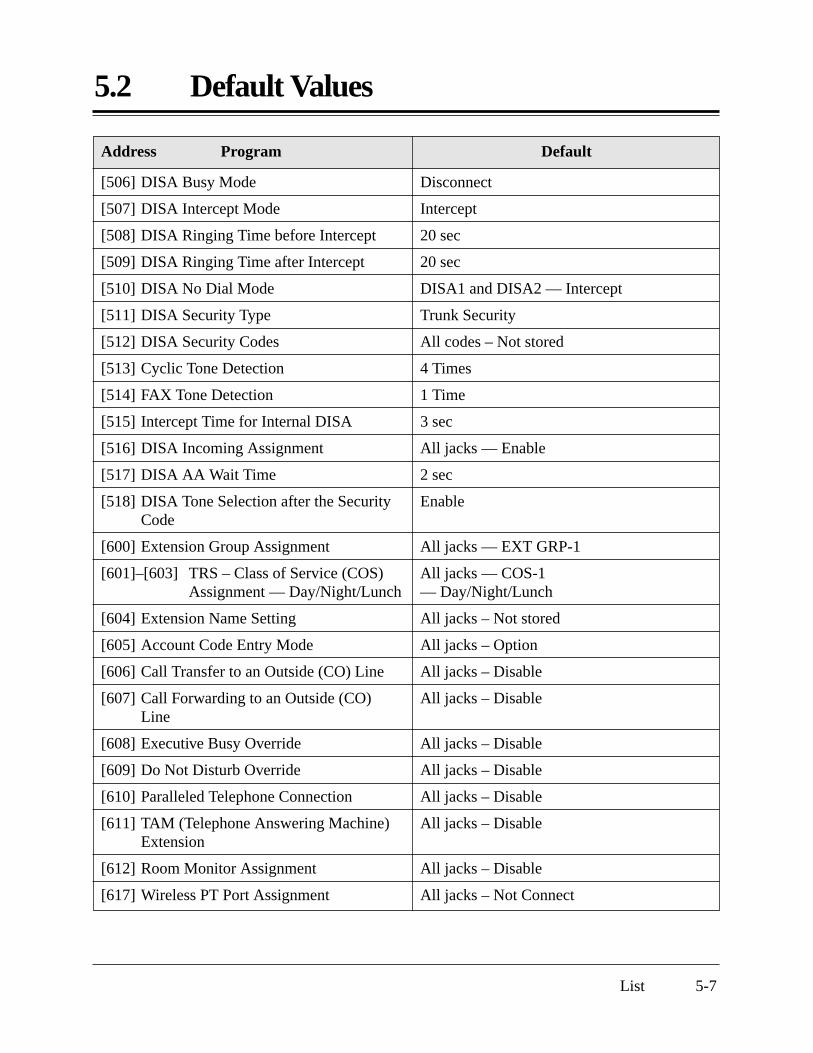
DefaultAddress Program
5.2 Default Values
List 5-7
[506] DISA Busy Mode
[507] DISA Intercept Mode
[508] DISA Ringing Time before Intercept
[509] DISA Ringing Time after Intercept
[510] DISA No Dial Mode
[511] DISA Security Type
[512] DISA Security Codes
[513] Cyclic Tone Detection
[514] FAX Tone Detection
[515] Intercept Time for Internal DISA
[516] DISA Incoming Assignment
[517] DISA AA Wait Time
[518] DISA Tone Selection after the SecurityCode
[600] Extension Group Assignment
[601]–[603] TRS – Class of Service (COS)Assignment — Day/Night/Lunch
[604] Extension Name Setting
[605] Account Code Entry Mode
[606] Call Transfer to an Outside (CO) Line
[607] Call Forwarding to an Outside (CO)Line
[608] Executive Busy Override
[609] Do Not Disturb Override
[610] Paralleled Telephone Connection
[611] TAM (Telephone Answering Machine)Extension
[612] Room Monitor Assignment
[617] Wireless PT Port Assignment
Disconnect
Intercept
20 sec
20 sec
DISA1 and DISA2 — Intercept
Trunk Security
All codes – Not stored
4 Times
1 Time
3 sec
All jacks — Enable
2 sec
Enable
All jacks — EXT GRP-1
All jacks — COS-1— Day/Night/Lunch
All jacks – Not stored
All jacks – Option
All jacks – Disable
All jacks – Disable
All jacks – Disable
All jacks – Disable
All jacks – Disable
All jacks – Disable
All jacks – Disable
All jacks – Not Connect

Address Program Default
5.2 Default Values
5-8 List
[700]–[702] Doorphone Ringing Assignment— Day/Night/Lunch
[703]–[705] Door Opener Assignment— Day/Night/Lunch
[706] Doorphone Ringing/Tone PatternSelection
[707] Doorphone Access Tone Selection
[708] Doorphone Ringing Time
[709] Door Opener Time
[800] SMDR RS-232C CommunicationParameters
[801] SMDR Parameter
[802] Incoming/Outgoing Call Selection forPrinting
[803] Secret Speed Dialing/One-Touch DialingPrinting
[804] System Data Dump
[805] SMDR Account Code Selection
[900] Caller ID Assignment
[901] Caller ID Area Code Assignment
[902] Caller ID Modification for Local Calls
[903] Caller ID Modification for LongDistance Calls
[904] Caller ID Log Priority Selection
[906] Caller ID SMDR Format
[998] ROM Version
[999] System Data Clear
All doorphones – all jacks – Enable — Day/Night/Lunch
All door openers – all jacks – Enable— Day/Night/Lunch
All doorphones — Triple
All doorphones — Enable
All doorphones — 15 sec
All door openers — 5 sec
New line code = CR+LF; Baud rate = 9600;Word length = 8; Parity bit = Mark;Stop bit = 1
Page length – 66; Skip perforation – 0
Outgoing calls – On; Incoming calls – On
No printing
Not applicable.
CODE
All outside (CO) lines – Disable
All codes – Not stored
Deleted digits – 3; Added number – blank
Deleted digits – 0; Added number – 1
All jacks – Name
With CID
Not applicable.
Not applicable.

Section 6Troubleshooting
This section provides information for system and telephone troubleshooting.

6-2 Troubleshooting
6.1 Installation
Extension does notoperate.
Improper reset operation.
Noise during externalpaging.
Volume distortion fromexternal music source.
Speed Dialing or One-Touch Dialing does notfunction.
A proprietary telephoneconnected to extensionjacks 01 through 08,09 through 16, or17 through 24 does notoperate, but a single linetelephone operates.
Something is wrong withthe printed circuit board(Extension Card).
Something is wrong withthe connection between thesystem and extension.
A telephone with an A-A1relay is connected.
Something is wrong withthe extension.
Induced noise on the wirebetween the system and theamplifier.
Excessive input level fromexternal music source.
Wrong programming.
An extension (H, L) jack01 through 08, 09 through16, or 17 through 24 mayhave been shorted.
Exchange the printed circuit boardwith another printed circuit board.
Take the extension and plug it intothe same extension port using ashort telephone cord. If thetelephone works correctly, theconnection between the system andthe extension must be repaired.
Use a 2 wire cord.Set the A-A1 relay switch on thetelephone to the “OUT” or “OFF”position.
Take the extension and plug it intoanother extension port that isworking. If the telephone does notwork, replace the phone.
Turn the Power Switch off and on.
Use a shielded cable as theconnection wire between thesystem and amplifier. A shortshielded cable is recommended.
Decrease the output level of theexternal music source by using thevolume control on the musicsource.
Enter an outside (CO) line accessnumber (9, 81 through 86) in programming.
Turn the Power Switch off and fixthe shorted part, then turn thePower Switch on.
PROBLEM PROBABLE CAUSE POSSIBLE SOLUTION

Troubleshooting 6-3
6.2 Connection
Yes
No
Connection between the system and a proprietary telephone:
T/R is connected to H/L.
H ¡
T ¡
R ¡
L ¡
¡ H¡ T¡ R¡ L
KX-TA624 extension
Use the correct cord (the inner 2 wires are for T/Rand the outer 2 wires are forH/L).
Connection between the system and a single line telephone:
Connection between the system and a single line telephone that is polarity-sensitive:
Can you dialan extension?
CAUSE SOLUTION
“T” is connected to “R”.
H ¡
T ¡
R ¡
L ¡
¡
¡ T¡ R¡
KX-TA624 extension
Reverse the connections ofT/R.
T/R is connected to H/L.
H ¡
T ¡
R ¡
L ¡
¡
¡ T¡ R¡
KX-TA624 extension
Use the correct cord (the inner 2 wires are forT/R).
Outside (CO) lines are connected to H/L.
¡
¡
¡
¡ T¡ R¡
Outside (CO) line KX-TA624
Reconnect the outside (CO)lines to T/R using 2-conductorwiring.
Connection between the central office and the system:
Can you dialout using anoutside (CO)line?
No
CAUSE SOLUTION
CAUSE SOLUTION
CAUSE SOLUTION

6-4 Troubleshooting
6.3 Operation
PROBLEM PROBABLE CAUSE POSSIBLE SOLUTION
When using the speaker-phone with a proprietarytelephone, KX-T7130 orKX-T7030, nothing isheard.
The unit does not ring.
During a power failure, theextension connected toJACK 01 or 09 does notoperate.
Originating an outside callcannot be performed.
A tone type single linetelephone (SLT) usercannot make a call.
The HANDSET/HEADSETselector on the KX-T7130or KX-T7030 is set to the“HEADSET” position.
The Ringer VolumeSelector is set to “OFF”.
A PT is connected to thejack.
The corresponding CObutton does not exist onthe proprietary telephone.
There may be somethingwrong with a DTMFreceiver.
When the headset is not used, setthe HANDSET/HEADSET selectorto the “HANDSET” position.
Set to “HIGH” or “LOW”.
Disconnect the PT and connect asingle line telephone.
Program the CO button. See theFlexible Button Assignment in theUser Manual.
1. Select “Enable” for DTMFreceiver 1 and “Disable” forDTMF receiver 2 in program[107].
2. Make a call using a tone typeSLT connected to one ofextension jacks 01 – 08.
3. If you cannot make the call, theproblem may have been causedby DTMF receiver 1. If the callcan be made, go to step 4.
4. Try DTMF receiver 2. Select“Disable” for DTMF receiver1 and “Enable” for DTMFreceiver 2 in program [107], andmake another call. If you cannotmake the call, the problem mayhave been caused by DTMFreceiver 2. If the call can bemade, go to step 5.
5. Check the other four DTMFreceivers in the same way. Referto program [107].

Section 7Programming Tables
This section provides a hard copy reference for entering user-programmed data.

7 Programming Tables
7-2 Programming Tables
[002] System Password
[003] DSS Console Port Assignment
[004] Paired Telephone Assignment for DSS Console
[005] One-Touch Transfer Using a DSS Button
[008] Operator Assignment [010] LCD Time Display Selection
[006] Time (Day/Night/Lunch) Service Changing Mode
[007] Time (Day/Night/Lunch) Service Start Time
[000] Date and Time Setting
Default ’98 Jan. 1 Thu 12 00 AM
Change
Year
(00 – 99)
Month
(Jan. – Dec.)
Day
(1 – 31)
Day of the week
(Sun – Sat)
Hour
(1 – 12)
Minute
(00 – 59)AM / PM
Parameter: 4 digits, 0 – 9Default
1 2 3 4
DSS console jack no. (02…24) / Disable Paired telephone jack no. (01…24) / DisableSelection
Default
DSS 1
DSS 2
All: Disable DSS 1 – Disable / DSS 2 – Disable
Default
Selection
With Transfer
Without Transfer
Default
Jack-01
Jack no.
Operator
Default
Selection
12 HOUR
24 HOUR
Default
Selection
Manually
Automatically
Every day
ChangeDefault
Every day
9:00 AM
5:00 PM
None
None
Day
Night
Lunch-S
Lunch-E
Sun. Mon. Tue. Wed. Thu. Fri. Sat.

Programming Tables 7-3
7 Programming Tables
[001] System Speed Dialing Entry
40
41
42
43
44
45
46
47
48
49
50
51
52
53
54
55
56
57
58
59
60
61
62
63
64
65
66
67
68
69
70
71
72
73
74
75
76
77
78
79
Default
00
01
02
03
04
05
06
07
08
09
10
11
12
13
14
15
16
17
18
19
20
21
22
23
24
25
26
27
28
29
30
31
32
33
34
35
36
37
38
39
All: Not stored
SPD no. Telephone number (32 digits max.)SPD no.Telephone number (32 digits max.)

7 Programming Tables
7-4 Programming Tables
(Continued)
90
91
92
93
94
95
96
97
98
99
Default
80
81
82
83
84
85
86
87
88
89
All: Not stored
SPD no. Telephone number (32 digits max.)SPD no.Telephone number (32 digits max.)
[604] Extension Name Setting
[009] Extension Number Assignment
[600] Extension Group Assignment
01
02
03
04
05
06
07
08
09
10
11
12
13
14
15
16
17
18
19
20
21
22
23
24
*
Default
101
102
103
104
105
106
107
108
109
110
111
112
113
114
115
116
117
118
119
120
121
122
123
124
Change 1 2 3 4 5 6 7 8
Default: All – Group 1
Default: All – Not stored
Extension jack no.
Extension no. (100…199)
Extension group no. (1…8) Extension name (10 character max.)
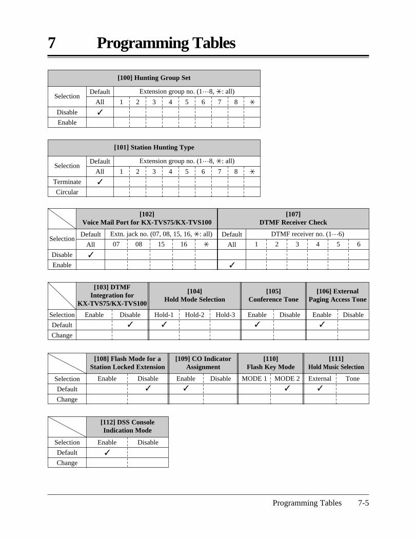
[103] DTMF Integration for
KX-TVS75/KX-TVS100
[104] Hold Mode Selection
[106] External Paging Access Tone
[105] Conference Tone
Programming Tables 7-5
7 Programming Tables
[100] Hunting Group Set
Disable
Enable
1 2 3 4 5 6 7 8 *
Extension group no. (1…8, *: all)Selection
Default
All
[102] Voice Mail Port for KX-TVS75/KX-TVS100
[107] DTMF Receiver Check
Default
All
Default
All
Disable
Enable
07
Extn. jack no. (07, 08, 15, 16, *: all)Selection
08 15 16 * 1
DTMF receiver no. (1…6)
2 3 4 5 6
Selection
Default
Change
[108] Flash Mode for aStation Locked Extension
[109] CO IndicatorAssignment
[110] Flash Key Mode
[111] Hold Music Selection
Enable External
ToneSelection
Default
Change
Disable
Enable
Disable MODE 1 MODE 2
[112] DSS ConsoleIndication Mode
Enable
Selection
Default
Change
Disable
[101] Station Hunting Type
Terminate
Circular
1 2 3 4 5 6 7 8 *
Extension group no. (1…8, *: all)Selection
Default
All
Enable Disable
Hold-1
Hold-2 Hold-3 Enable
Disable Enable
Disable

[131] Voice Mail 2 APT Port for KX-TVS50
[130] Voice Mail 1 APT Port for KX-TVS50
7 Programming Tables
7-6 Programming Tables
Single Double
Triple
[115] Extension Ringing Pattern Selection
[117] Call Pickup Tone
Selection
Default
Change
Enable
Disable
[118] Pulse Restriction
Enable
Disable
[125] Toll Restriction Check for ** and #
DisableEnable
[119] Redialing after Pulse to Tone Conversion
Selection
Default
Change
Enable Disable
Port 15 & 16Port 15Selection
Default
Change
Port 7 Port 7 & 8 Disable
Disable
[203] Pickup Dial Delay Time
[200] Hold Recall Time
[204] Call Duration Count Start Time
[201] Transfer Recall Time
[202] Call Forwarding Start Time
30 sec
1 minSelection
Default
Change
5 sec 10 sec
15 sec 20 sec 25 sec 30 sec 35 sec 40 sec 45 sec 50 sec InstantlySelection
Default
Change
1.5 min 2 min 3 min 4 min 5 min 6 min Disable
15 sec 30 sec
1 min 2 minSelection
Default
Change
5 sec 10 sec 15 sec
20 sec 1 sec 2 sec 3 sec
4 sec

Programming Tables 7-7
7 Programming Tables
[205] Outside-to-Outside (CO-to-CO) Line Duration Time Limit
1…32 minutes
10 minutes
Selection
Default
Change
[208] Interdigit Time [211] No Dial Disconnection
Selection
Default
Change
5 sec 10 sec
15 sec
[300] Carrier Code Assignment
11
12
13
14
15
16
17
18
19
20
Default: All Not stored
CODE no. Carrier code (10 digits max.)CODE no.Carrier code (10 digits max.)
[301] Toll Restriction — System Speed Dialing Boundary Class
Class-1
Class-2Selection
Default
Change
Class-3 Class-4 Class-5
[206] Dialing Start Time
Selection
Default
Change
0 ms
250 ms 500 ms 750 ms 1000 ms 1250 ms 1500 ms
01
02
03
04
05
06
07
08
09
10
Enable Disable

7 Programming Tables
7-8 Programming Tables
[302] Toll Restriction –Class 2 Denied Codes
[303] Toll Restriction –Class 3 Denied Codes
[304] Toll Restriction –Class 4 Denied Codes
[305] Toll Restriction –Class 5 Denied Codes
Default
01
02
03
04
05
06
07
08
09
10
11
12
13
14
15
16
17
18
19
20
CODEno. Telephone no. (11 digits)
All: Not stored
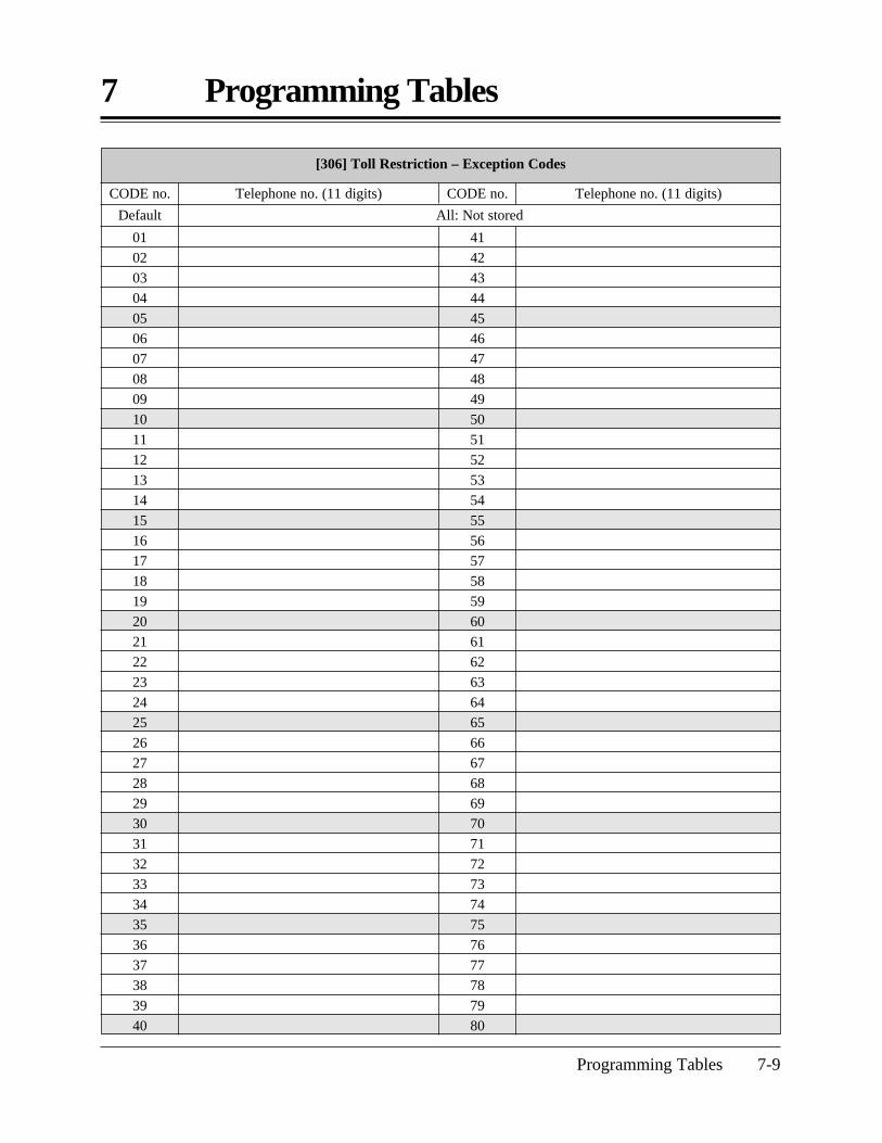
Programming Tables 7-9
7 Programming Tables
[306] Toll Restriction – Exception Codes
41
42
43
44
45
46
47
48
49
50
51
52
53
54
55
56
57
58
59
60
61
62
63
64
65
66
67
68
69
70
71
72
73
74
75
76
77
78
79
80
Default All: Not stored
CODE no. Telephone no. (11 digits)CODE no.Telephone no. (11 digits)
01
02
03
04
05
06
07
08
09
10
11
12
13
14
15
16
17
18
19
20
21
22
23
24
25
26
27
28
29
30
31
32
33
34
35
36
37
38
39
40
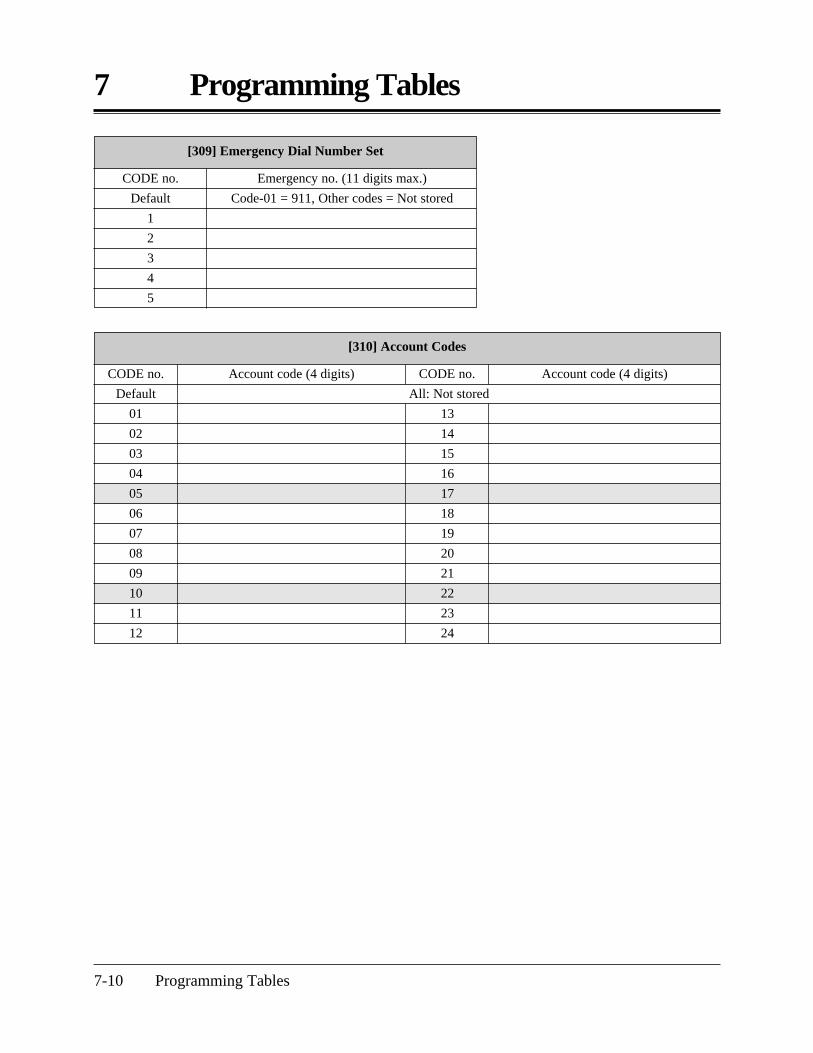
7 Programming Tables
7-10 Programming Tables
[309] Emergency Dial Number Set
CODE no.
Default
1
2
3
4
5
Emergency no. (11 digits max.)
Code-01 = 911, Other codes = Not stored
[310] Account Codes
13
14
15
16
17
18
19
20
21
22
23
24
All: Not storedDefault
01
02
03
04
05
06
07
08
09
10
11
12
CODE no. Account code (4 digits)CODE no.Account code (4 digits)

Programming Tables 7-11
7 Programming Tables
[311] Automatic Pause Insertion Codes
21
22
23
24
25
26
27
28
29
30
31
32
33
34
35
36
37
38
39
40
Default
01
02
03
04
05
06
07
08
09
10
11
12
13
14
15
16
17
18
19
20
All: Not stored
CODE no. Pause code (7 digits max.)CODE no.Pause code (7 digits max.)
[312] Toll Restriction – Station Lock Boundary Class
Default
Change
Disable
COS-2
COS-3
COS-4
COS-5

7 Programming Tables
7-12 Programming Tables
[402] Pulse Speed Selection
[400] Outside (CO) LineConnection Assignment
[401] Dial Mode
Selection
Connect
No Connect
Selection
Low Speed
High Speed
Selection
DTMF
Pulse Call Blocking
Outside line no.
Default: All
1
2
3
4
5
6
*
[404] Outside (CO) Line Group Assignment
[403] Host PBX Access Codes
Outside line group no.(1…6)
Access codes (1 or 2 digits, 8 different codes max.)
All: Not stored
Outside line no.
Default
1
2
3
4
5
6
*
Default
1
2
3
4
5
6
—
Change

Programming Tables 7-13
7 Programming Tables
[405] Flexible Outward Dialing Assignment — Day
Default: All
01
02
03
04
05
06
07
08
09
10
11
12
13
14
15
16
17
18
19
20
21
22
23
24
*
Extensionjack no.
Outside line 1
Enable
Disable
Outside line 2 Outside line 3 Outside line 4 Outside line 5 Outside line 6 * (All)
Selection
Enable
Disable Enable
Disable Enable
Disable Enable
Disable Enable
Disable Enable
Disable
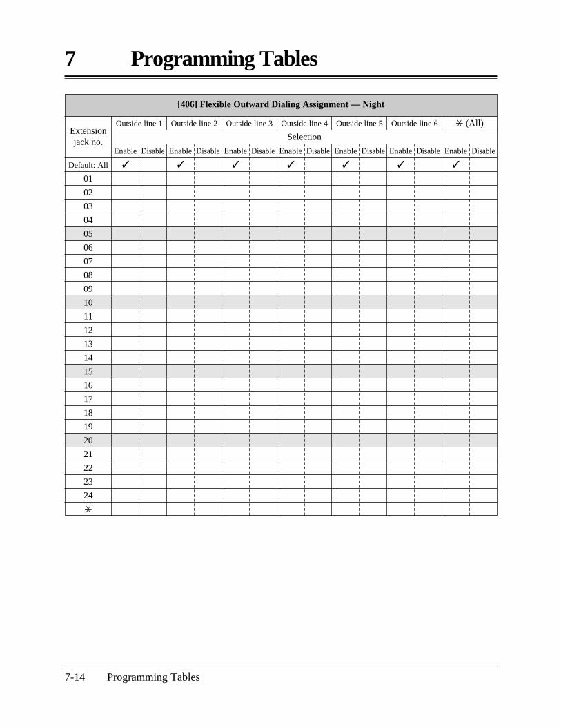
7 Programming Tables
7-14 Programming Tables
[406] Flexible Outward Dialing Assignment — Night
Default: All
01
02
03
04
05
06
07
08
09
10
11
12
13
14
15
16
17
18
19
20
21
22
23
24
*
Extensionjack no.
Outside line 1
Enable
Disable
Outside line 2 Outside line 3 Outside line 4 Outside line 5 Outside line 6 * (All)
Selection
Enable
Disable Enable
Disable Enable
Disable Enable
Disable Enable
Disable Enable
Disable

Programming Tables 7-15
7 Programming Tables
[407] Flexible Outward Dialing Assignment — Lunch
Default: All
01
02
03
04
05
06
07
08
09
10
11
12
13
14
15
16
17
18
19
20
21
22
23
24
*
Extensionjack no.
Outside line 1
Enable
Disable
Outside line 2 Outside line 3 Outside line 4 Outside line 5 Outside line 6 * (All)
Selection
Enable
Disable Enable
Disable Enable
Disable Enable
Disable Enable
Disable Enable
Disable

7 Programming Tables
7-16 Programming Tables
[408] Flexible Ringing Assignment — Day
Default: All
01
02
03
04
05
06
07
08
09
10
11
12
13
14
15
16
17
18
19
20
21
22
23
24
*
Extensionjack no.
Outside line 1
Enable
Disable
Outside line 2 Outside line 3 Outside line 4 Outside line 5 Outside line 6 * (All)
Selection
Enable
Disable Enable
Disable Enable
Disable Enable
Disable Enable
Disable Enable
Disable

Programming Tables 7-17
7 Programming Tables
[409] Flexible Ringing Assignment — Night
Default: All
01
02
03
04
05
06
07
08
09
10
11
12
13
14
15
16
17
18
19
20
21
22
23
24
*
Extensionjack no.
Outside line 1
Enable
Disable
Outside line 2 Outside line 3 Outside line 4 Outside line 5 Outside line 6 * (All)
Selection
Enable
Disable Enable
Disable Enable
Disable Enable
Disable Enable
Disable Enable
Disable

7 Programming Tables
7-18 Programming Tables
[410] Flexible Ringing Assignment — Lunch
Default: All
01
02
03
04
05
06
07
08
09
10
11
12
13
14
15
16
17
18
19
20
21
22
23
24
*
Extensionjack no.
Outside line 1
Enable
Disable
Outside line 2 Outside line 3 Outside line 4 Outside line 5 Outside line 6 * (All)
Selection
Enable
Disable Enable
Disable Enable
Disable Enable
Disable Enable
Disable Enable
Disable

Programming Tables 7-19
7 Programming Tables
[411] Delayed Ringing Assignment — Day
Default: All
01
02
03
04
05
06
07
08
09
10
11
12
13
14
15
16
17
18
19
20
21
22
23
24
*
Extensionjack no.
Outside line 1
I
5 10 15
Outside line 2 Outside line 3 Outside line 4 Outside line 5 Outside line 6 * (All)
Selection (I: Immediately, 5: 5 seconds delay, 10: 10 seconds delay, 15: 15 seconds delay)
I
5 10 15 I
5 10 15 I
5 10 15 I
5 10 15 I
5 10 15 I
5 10 15

7 Programming Tables
7-20 Programming Tables
[412] Delayed Ringing Assignment — Night
Default: All
01
02
03
04
05
06
07
08
09
10
11
12
13
14
15
16
17
18
19
20
21
22
23
24
*
Extensionjack no.
Outside line 1
I
5 10 15
Outside line 2 Outside line 3 Outside line 4 Outside line 5 Outside line 6 * (All)
Selection (I: Immediately, 5: 5 seconds delay, 10: 10 seconds delay, 15: 15 seconds delay)
I
5 10 15 I
5 10 15 I
5 10 15 I
5 10 15 I
5 10 15 I
5 10 15
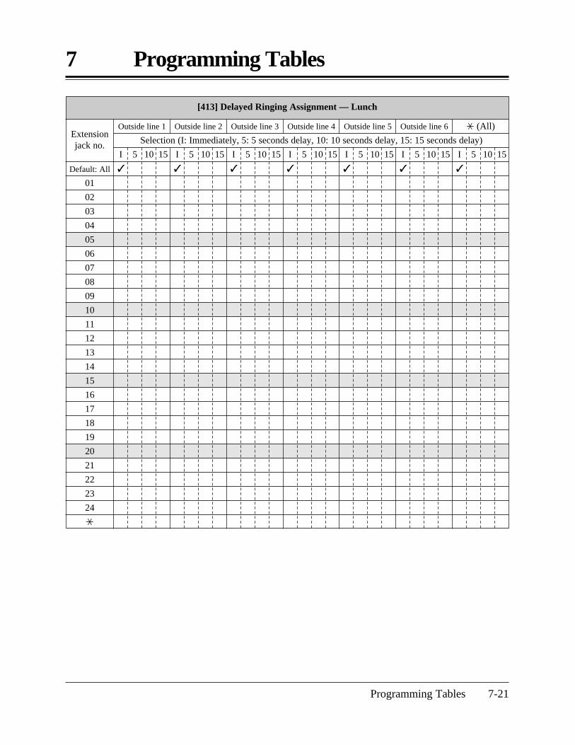
Programming Tables 7-21
7 Programming Tables
[413] Delayed Ringing Assignment — Lunch
Default: All
01
02
03
04
05
06
07
08
09
10
11
12
13
14
15
16
17
18
19
20
21
22
23
24
*
Extensionjack no.
Outside line 1
I
5 10 15
Outside line 2 Outside line 3 Outside line 4 Outside line 5 Outside line 6 * (All)
Selection (I: Immediately, 5: 5 seconds delay, 10: 10 seconds delay, 15: 15 seconds delay)
I
5 10 15 I
5 10 15 I
5 10 15 I
5 10 15 I
5 10 15 I
5 10 15
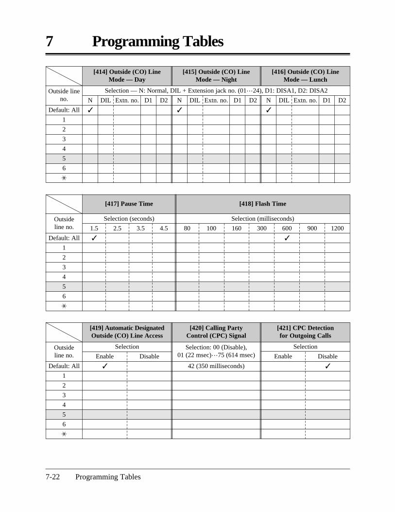
7 Programming Tables
7-22 Programming Tables
[416] Outside (CO) Line Mode — Lunch
[414] Outside (CO) Line Mode — Day
[415] Outside (CO) Line Mode — Night
Default: All
1
2
3
4
5
6
*
DIL Extn. no. D1 D2
Outside lineno. N
DIL Extn. no. D1 D2N
DIL Extn. no. D1 D2N
Selection — N: Normal, DIL + Extension jack no. (01…24), D1: DISA1, D2: DISA2
[417] Pause Time [418] Flash Time
Selection (seconds)
1.5
2.5 4.53.5
Selection (milliseconds)
80 100 160 300 600
900 1200
Outside line no.
Default: All
1
2
3
4
5
6
*
[421] CPC Detection for Outgoing Calls
[419] Automatic DesignatedOutside (CO) Line Access
[420] Calling Party Control (CPC) Signal
Enable
42 (350 milliseconds)
SelectionSelection Selection: 00 (Disable), 01 (22 msec)…75 (614 msec) EnableDisable Disable
Outside line no.
Default: All
1
2
3
4
5
6
*

Programming Tables 7-23
7 Programming Tables
[503] FAX Connection[502]
OGM Mode Selection
[423] Outside (CO) Line Ringing Pattern Selection
[422] Disconnect Time
Selection (seconds) SelectionOutside line no.
Default: All
1
2
3
4
5
6
*
0.5 4.0 Single
Double Triple1.5
[500] DISA Incoming Dialing Mode Selection
Selection
Default
Change
Without AA
With AA
Default
0
1
2
3
4
5
6
7
8
9
[501] DISA Built-in Auto Attendant
Auto attendantno.
Selection
Jack: Extension jack no. (01…24) GRP: Ring group no. (1…8)
All: Not stored
MODE 1
MODE 2 Extension jack no. (01…24) / Disable
Disable
[504] DISA Delayed Answer Time [505] DISA Waiting Time after OGM
0 sec 3 sec
Selection
Default
Change
6 sec 12 sec 0 sec 5 sec
10 sec 15 sec

7 Programming Tables
7-24 Programming Tables
Intercept
[506] DISA Busy Mode
[507] DISA Intercept Mode
[508] DISA Ringing Time before Intercept
[509] DISA Ringing Time after Intercept [510] DISA No Dial Mode
Disconnect
Call WaitingSelection
Default
Change
DISA 2 Intercept
Disconnect 10 sec 20 sec
30 sec 40 sec 60 sec 120 sec
10 secSelection
Default
Change
DISA 1
Disconnect30 sec 40 sec 60 sec
Intercept
DISA 2
Disconnect120 sec20 sec
[511] DISA Security Type [512] DISA Security Codes [513] Cyclic Tone Detection
Trunk
All
CODE=01 CODE=02 CODE=03 CODE=04
Selection
Default
Change
None 0…9, 4 digit
All codes = Not stored
2 TimesDisable 3 Times 4 Times
[514] FAX Tone Detection
[515] Intercept Time for Internal DISA
[517] DISA AA Wait Time
1 Time
2 Times 6 sec 9 secSelection
Default
Change
3 sec
1 sec 2 sec
3 sec 4 sec 5 sec
[516] DISA Incoming Assignment
Extension jack no.
Extension jack no.
Extension jack no.
Default: All
01
02
03
04
05
06
07
08
09
10
11
12
13
14
15
16
17
Selection
Enable
Disable
18
19
20
21
22
23
24
*
Selection
Enable Disable
Selection
Enable Disable

Programming Tables 7-25
7 Programming Tables
[518] DISA Tone Selection after the Security Code
Enable
DisableSelection
Default
Change
[601] TRS – Class of Service (COS) Assignment — Day
Default: All
01
02
03
04
05
06
07
08
09
10
11
12
13
14
15
16
17
18
19
20
21
22
23
24
*
Extension jack no.
COS no. (1…5)
1
2 3 4 5
[602] TRS – Class of Service (COS) Assignment — Night
COS no. (1…5)
1
2 3 4 5
[603] TRS – Class of Service (COS) Assignment — Lunch
COS no. (1…5)
1
2 3 4 5

7 Programming Tables
7-26 Programming Tables
[606] Call Transfer to Outside (CO) Line
[605] Account Code Entry Mode
Default: All
01
02
03
04
05
06
07
08
09
10
11
12
13
14
15
16
17
18
19
20
21
22
23
24
*
Extension jack no. Verify-All Verify-Toll
Selection
Option
Forced
Selection
Enable Disable
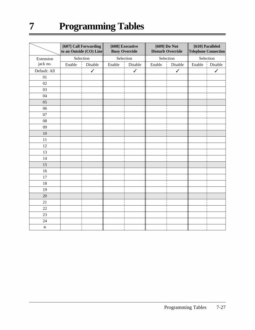
Programming Tables 7-27
7 Programming Tables
[609] Do Not Disturb Override
[607] Call Forwarding to an Outside (CO) Line
[608] Executive Busy Override
Default: All
01
02
03
04
05
06
07
08
09
10
11
12
13
14
15
16
17
18
19
20
21
22
23
24
*
Extension jack no.
Selection
Enable Disable
Selection
Enable Disable
Selection
Enable Disable
[610] ParalleledTelephone Connection
Selection
Enable Disable
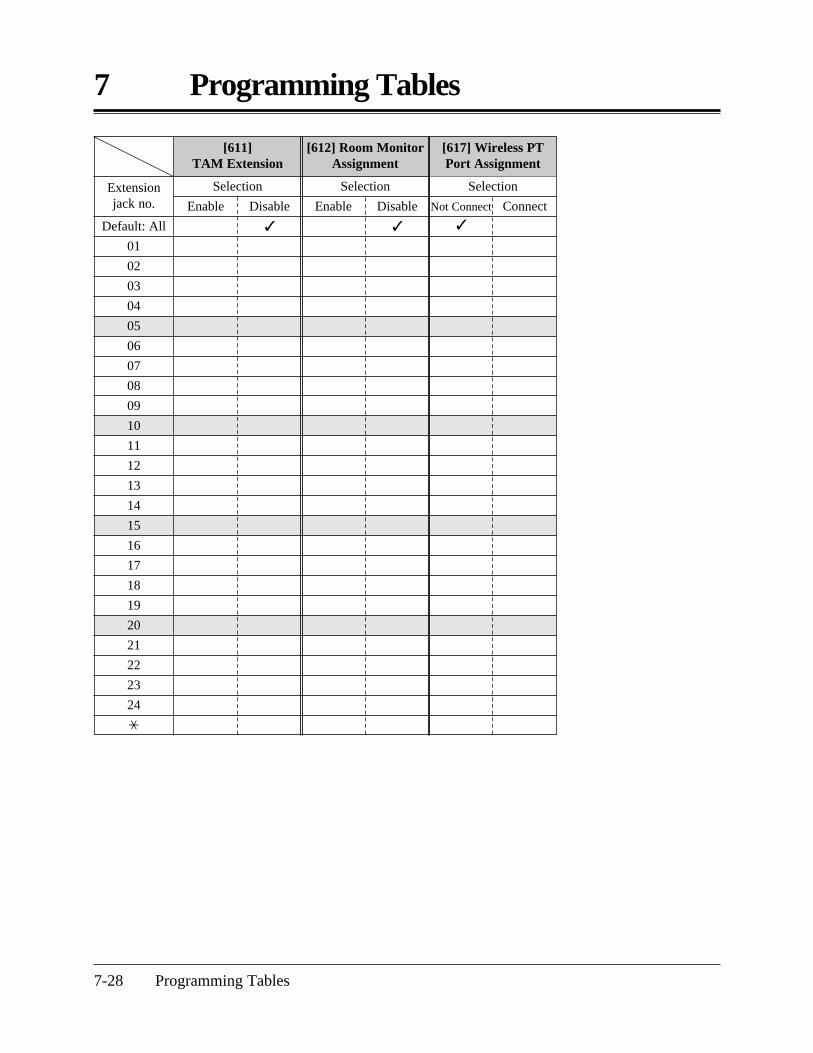
7 Programming Tables
7-28 Programming Tables
[612] Room MonitorAssignment
[611] TAM Extension
Default: All
01
02
03
04
05
06
07
08
09
10
11
12
13
14
15
16
17
18
19
20
21
22
23
24
*
Extension jack no.
Selection
Enable Disable
Selection
Enable Disable
[617] Wireless PTPort Assignment
Selection
Not Connect
Connect

Programming Tables 7-29
7 Programming Tables
[700] Doorphone RingingAssignment — Day
[701] Doorphone RingingAssignment — Night
[702] Doorphone RingingAssignment — Lunch
Default: All
01
02
03
04
05
06
07
08
09
10
11
12
13
14
15
16
17
18
19
20
21
22
23
24
*
Extension jack no. 1
E
D
2
E
D
3
E
D
4
E
D
1
E
D
2
E
D
3
E
D
4
E
D
1
E
D
2
E
D
3
E
D
4
E
D
1…4: Doorphone no., E: Enable / D: Disable
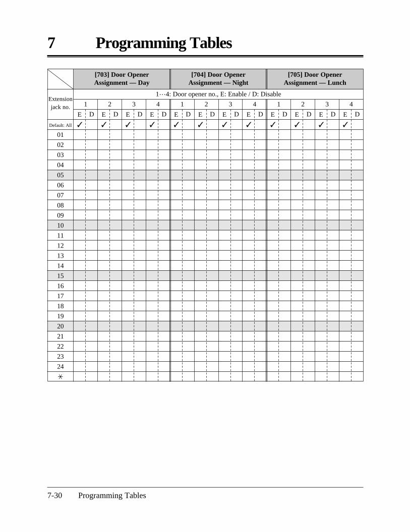
7 Programming Tables
7-30 Programming Tables
[703] Door Opener Assignment — Day
[704] Door Opener Assignment — Night
[705] Door Opener Assignment — Lunch
Default: All
01
02
03
04
05
06
07
08
09
10
11
12
13
14
15
16
17
18
19
20
21
22
23
24
*
Extension jack no. 1
E
D
2
E
D
3
E
D
4
E
D
1
E
D
2
E
D
3
E
D
4
E
D
1
E
D
2
E
D
3
E
D
4
E
D
1…4: Door opener no., E: Enable / D: Disable

Programming Tables 7-31
7 Programming Tables
[706] Doorphone Ringing / Tone Pattern Selection
[708] Doorphone Ringing Time
[707] Doorphone Access Tone Selection
Default: All
1
2
3
4
*
Doorphone no. Single
Selection Selection Selection
Double Triple
S-Double 15 sec
30 secEnable
Disable
Selection
[801] SMDR Parameter [802] Incoming/Outgoing Call Selection for Printing
[709] Door Opener Time
[800] SMDR RS-232C Communication Parameters
Default: All
1
2
3
4
*
Door opener no. 1 sec 2 sec 3 sec 4 sec 5 sec
6 sec 7 sec 8 sec
Selection
Default
Change
CR+LF
CR 150 300 600 1200 2400 4800 9600
21
Mark
Space Even Odd None
Stop bitParity bit
8
7
Wordlength
Baud rateNew line code
Default
On
Off
On
Off
Toll
Selection
Incoming calls
Outgoing calls
Default Selection
Page length(4…99)
66
0Skip perforation
(0…95)

7 Programming Tables
7-32 Programming Tables
Default
3
blank (not stored)
0
1
Change Default Change
[902] Caller ID Modification for Local Calls
[903] Caller ID Modification for Long Distance Calls
Number of digits to be deleted(0…9, 0: no deletion)
Number to be added (4 digits max.)
Selection
Outside (CO) line no. (1…6, : All)
[900] Caller ID Assignment
Enable
Disable
SelectionDefault
All
1 2 3 4 5 6
[803] Secret Speed Dialing / One-Touch Dialing Printing
[805] SMDR Account Code Selection
No Printing
CODE
Printing INDEXSelection
Default
Change
[901] Caller ID Area Code Assignment
CODE no.
Default
1
2
3
4
5
Parameter: 6 digits max., 0 – 9
All: Not stored
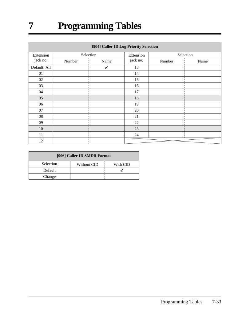
Programming Tables 7-33
7 Programming Tables
[904] Caller ID Log Priority Selection
13
14
15
16
17
18
19
20
21
22
23
24
Default: All
01
02
03
04
05
06
07
08
09
10
11
12
Extension jack no.
Selection
Number Name
Extension jack no.
Selection
Number Name
[906] Caller ID SMDR Format
Default
Change
Selection Without CID With CID

PSQX1424WA KW0698KM6020APC (M)
Panasonic Consumer ElectronicsCompany, Division of MatsushitaElectric Corporation of AmericaOne Panasonic Way, Secaucus, New Jersey 07094
Panasonic Sales Company (“PSC”),Division of Matsushita Electric ofPuerto Rico, Inc. Ave. 65 de Infantería, Km. 9.5, San Gabriel Industrial Park, Carolina, Puerto Rico 00985
Printed in the United Kingdom
Copyright:
This manual is copyrighted by Kyushu Matsushita Electric Co., Ltd. (KME). Under the copyright laws, thismanual may not be reproduced in any form, in whole or part, without the prior written consent of KME andits licensee.
C 1999 Kyushu Matsushita Electric Co., Ltd. All Rights Reserved.