Embed Size (px)
Citation preview
R-410A OUTDOOR SPLIT-SYSTEM AIR CONDITIONINGMODELS: 13, 14 & 17 SEER YCD, YFD, YCE, YCS, YFE, YCG, TC3, TCD, TF3, TC4, TW4, TF4, TC7, CC7, RAC13L, RAC13F, RAC14L, RAW14L, RAC14F, RAC17L SERIES1.5 TO 5 TONS – 1 & 3 PHASE
INSTALLATION MANUAL®
LIST OF SECTIONSGENERAL . . . . . . . . . . . . . . . . . . . . . . . . . . . . . . . . . . . . . . . . . . . . . .1SAFETY . . . . . . . . . . . . . . . . . . . . . . . . . . . . . . . . . . . . . . . . . . . . . . . .1UNIT INSTALLATION . . . . . . . . . . . . . . . . . . . . . . . . . . . . . . . . . . . . .2COIL METERING DEVICES . . . . . . . . . . . . . . . . . . . . . . . . . . . . . . . .5EVACUATION . . . . . . . . . . . . . . . . . . . . . . . . . . . . . . . . . . . . . . . . . . .7
SYSTEM CHARGE . . . . . . . . . . . . . . . . . . . . . . . . . . . . . . . . . . . . . . 7ELECTRICAL CONNECTIONS . . . . . . . . . . . . . . . . . . . . . . . . . . . . . 9INSTRUCTING THE OWNER . . . . . . . . . . . . . . . . . . . . . . . . . . . . . 12WIRING DIAGRAM . . . . . . . . . . . . . . . . . . . . . . . . . . . . . . . . . . . . . 13START UP SHEET . . . . . . . . . . . . . . . . . . . . . . . . . . . . . . . . . . . . . . 15
LIST OF FIGURESTypical Installation . . . . . . . . . . . . . . . . . . . . . . . . . . . . . . . . . . . . . . . .3Installation of Vapor Line . . . . . . . . . . . . . . . . . . . . . . . . . . . . . . . . . . .4Underground Installation . . . . . . . . . . . . . . . . . . . . . . . . . . . . . . . . . . .4Heat Protection . . . . . . . . . . . . . . . . . . . . . . . . . . . . . . . . . . . . . . . . . .4Recommended Distributor Adjustment . . . . . . . . . . . . . . . . . . . . . . . .6Piston Installation . . . . . . . . . . . . . . . . . . . . . . . . . . . . . . . . . . . . . . . . .6TXV Installation . . . . . . . . . . . . . . . . . . . . . . . . . . . . . . . . . . . . . . . . . .6TXV Bulb and Equalizer line Installations . . . . . . . . . . . . . . . . . . . . . .7Proper Bulb Location . . . . . . . . . . . . . . . . . . . . . . . . . . . . . . . . . . . . . .7Vertical Temperature Bulb Orientation . . . . . . . . . . . . . . . . . . . . . . . . .7Outdoor Unit Swing Away Control Box . . . . . . . . . . . . . . . . . . . . . . . .9
Outdoor Unit Control Box (Single Phase - Smaller Base) . . . . . . . . 10Outdoor Unit Control Box (Single Phase - Larger Base) . . . . . . . . . 10Outdoor Unit Control Box (Three Phase) . . . . . . . . . . . . . . . . . . . . . 10Typical Field Wiring (Air Handler / Electrical Heat) (Single-Phase) . . . . . . . . . . . . . . . . . . . . . . . . . . . . . 11Thermostat Chart - PSC Air Handler with Single Stage Air Conditioner . . . . . . . . . . . . . . . . . . . . . . . . . . . . . . . 11Thermostat Chart - Single Stage PSC Furnace with Single Stage Air Conditioner . . . . . . . . . . . . . . . . . . . . . . . . . . . . . . . 12Wiring Diagram - Single Phase 13 & 14 Seer . . . . . . . . . . . . . . . . . . 13Wiring Diagram - Single Phase 17 Seer . . . . . . . . . . . . . . . . . . . . . . 14
LIST OF TABLESApplication Limitations . . . . . . . . . . . . . . . . . . . . . . . . . . . . . . . . . . . . .2 R-410A Saturation Properties . . . . . . . . . . . . . . . . . . . . . . . . . . . . . . . 8
SECTION I: GENERALThese outdoor condensing units are designed to be connected to amatching UPG indoor coil. They are equipped with a filter-drier locatedin the liquid line.Units with quick-connect coupling connections are factory charged withrefrigerant to be matched with the appropriate pre-charged line set, andUPG indoor coil.
SECTION II: SAFETYThis is a safety alert symbol. When you see this symbol onlabels or in manuals, be alert to the potential for personalinjury.
Understand and pay particular attention to the signal words DANGER,WARNING, or CAUTION. DANGER indicates an imminently hazardous situation, which, if notavoided, will result in death or serious injury.WARNING indicates a potentially hazardous situation, which, if notavoided, could result in death or serious injury.CAUTION indicates a potentially hazardous situation, which, if notavoided may result in minor or moderate injury. It is also used toalert against unsafe practices and hazards involving only property dam-age.
WARNINGImproper installation may create a condition where the operation ofthe product could cause personal injury or property damage.Improper installation, adjustment, alteration, service or maintenancecan cause injury or property damage. Refer to this manual for assis-tance or for additional information, consult a qualified contractor,installer or service agency.
CAUTIONThis product must be installed in strict compliance with the enclosedinstallation instructions and any applicable local, state, and nationalcodes including, but not limited to building, electrical, and mechanicalcodes.
CAUTIONR-410A systems operate at higher pressures than R-22 systems. Donot use R-22 service equipment or components on R-410A equip-ment. Service equipment Must Be Rated for R-410A.
!
!
!
Johnson Controls Unitary Products 1183509-UIM-H-0416

1183509-UIM-H-0416
INSPECTIONAs soon as a unit is received, it should be inspected for possible dam-age during transit. If damage is evident, the extent of the damageshould be noted on the carrier’s delivery receipt. A separate request forinspection by the carrier’s agent should be made in writing. See LocalDistributor for more information.
Requirements For Installing/Servicing R-410A Equipment• Gauge sets, hoses, refrigerant containers, and recovery system
must be designed to handle the POE type oils, and the higherpressures of R-410A.
• Manifold sets should be high side and low side with low sideretard.
• All hoses must have a 700 psig service pressure rating.• Leak detectors should be designed to detect HFC refrigerant.• Recovery equipment (including refrigerant recovery containers)
must be specifically designed to handle R-410A.• Do not use an R-22 TXV.
LIMITATIONSThe unit should be installed in accordance with all National, State andLocal Safety Codes and the limitations listed below:1. Limitations for the indoor unit, coil, and appropriate accessories
must also be observed.2. The outdoor unit must not be installed with any duct work in the air
stream. The outdoor fan is the propeller type and is not designedto operate against any additional external static pressure.
3. The maximum and minimum conditions for operation must beobserved to ensure a system that will give maximum performancewith minimum service.
4. The unit should not be operated at outdoor temperatures below55°F without an approved low ambient operation accessory kitinstalled.
5. The maximum allowable line length for this product is 80 feet. Toinstall more than the maximum allowable line length, consult thePiping Application Guide (P/N 24077).
SECTION III: UNIT INSTALLATIONLOCATIONBefore starting the installation, select and check the suitability of thelocation for both the indoor and outdoor unit. Observe all limitations andclearance requirements.The outdoor unit must have sufficient clearance for air entrance to thecondenser coil, air discharge, and service access. See Figure 1.
If the unit is to be installed on a hot sun exposed roof or a paved groundarea that is seasonally hot, the unit should be raised sufficiently abovethe roof or ground to avoid taking the accumulated layer of hot air intothe outdoor unit.If the system is being installed during seasonally cold weather of 55°For below, the preferred method is to weigh in the charge. For chargingor checking the system charge at 55°F or below, refer to the “OptionalCold Weather Charging” procedures near the end of SECTION VI:SYSTEM CHARGE. There is an “Optional Cold Weather Charging”accessory kit to prevent the outdoor unit from taking in cold air below55°F. The kit part number can be found in the list of accessory kits onthe UPGNET web site.Provide adequate structural support for the unit.
ADD-ON REPLACEMENT/RETROFITWhen this unit is being used as a replacement for an R-410A unit, it isrequired that the outdoor unit, indoor coil, and metering device all bereplaced. The following steps should be performed in order to insureproper system operation and performance. Line-set change out is alsorecommended.1. Change-out of the indoor coil to an approved R-410A coil/ con-
densing unit combination with the appropriate metering device.2. Change-out of the line-set when replacing an R-22 unit with an
R410-A unit is highly recommended to reduce cross-contamina-tion of oils and refrigerants.
3. If change-out of the line set is not practical, then the following pre-cautions should be taken.
• Inspect the line set for kinks, sharp bends, or other restrictions,and for corrosion.
• Determine if there are any low spots which might be serving as oiltraps.
• Flush the line set with a commercially available flush kit toremove as much of the existing oil and contaminants as possible.
• Install a suction line filter-drier to trap any remaining contami-nants, and remove after 50 hours of operation.
4. If the outdoor unit is being replaced due to a compressor burnout,then installation of a 100% activated alumina suction-line filterdrier in the suction-line is required, in addition to the factoryinstalled liquid-line drier. Operate the system for 10 hours. Monitorthe suction drier pressure drop. If the pressure drop exceeds 3psig, replace both the suction-line and liquid-line driers. After atotal of 10 hours run time where the suction-line pressure drop hasnot exceeded 3 psig, replace the liquid line drier, and remove thesuction-line drier. Never leave a suction-line drier in the systemlonger than 50 hours of run time.
TABLE 1: Application Limitations
Ambient Air Temperature
on Outdoor Coil
Air Temperature on
Indoor CoilMODEL Min. DB Max. DB Min. WB Max. WB
YCD/TC3/RAC13L 55°F 115°F 57°F 72°FYCS/YFE/YCE/TW4/TF4/TC4/
RAC14L/RAW14L/RAC14F/YCG/TC7/CC7/RAC17L
55°F 125°F 57°F 72°F
NOTICEFor multiple unit installations, units must be spaced a minimum of 24”(61 cm) apart (coil face to coil face).
2 Johnson Controls Unitary Products

1183509-UIM-H-0416
GROUND INSTALLATIONThe unit should be installed on a solid base that is 2” (5.1 cm) abovegrade and will not shift or settle, causing strain on the refrigerant linesand possible leaks. Maintain the clearances shown in Figure 1 andinstall the unit in a level position. The base pad should not come in con-tact with the foundation or side of the structure because sound may betransmitted to the residence.The length of the refrigerant tubing between the outdoor unit and indoorcoil should be as short as possible to avoid capacity and efficiencylosses. Excessive spacing of the outdoor unit from the home can resultin the refrigerant lines being restricted by trampling or being puncturedby lawn mowers. Locate the outdoor unit away from bedroom windowsor other rooms where sound might be objectionable.Adverse effects of snow or sleet accumulating on the outdoor coil canbe eliminated by placing the outdoor unit where the prevailing winddoes not blow across the unit. Trees, shrubs, corners of buildings, andfences standing off from the coil can reduce capacity loss due to windchill effect.Provide ample clearance from shrubs to allow adequate air to passacross the outdoor coil without leaves or branches being pulled into thecoil.
ROOF INSTALLATIONWhen installing units on a roof, the structure must be capable of sup-porting the total weight of the unit, including a pad, lintels, rails, etc.,which should be used to minimize the transmission of sound or vibra-tion into the conditioned space.
WALL MOUNT INSTALLATIONCare must be taken to mount the outdoor unit on a solid base that issloped to shed water, secure from settlement, and is isolated from thestructural foundation or walls to prevent sound and vibration transmis-sion into the living space.
On occasion, site conditions may require direct wall mounted bracketsto be used to locate and support the outdoor unit. In these applications,care must be taken to address unit base pan support, structural integ-rity, safe access and serviceability, as well as the possible sound andvibration transmission into the structure. These applications are bestserved by a properly engineered solution.
LIQUID LINE FILTER-DRIERThe air conditioning unit’s filter/dryer is located inside the unit on the liq-uid line between the outdoor coil and the liquid valve inside the unit.
PIPING CONNECTIONSThe outdoor condensing unit must be connected to the indoor evapora-tor coil using field supplied refrigerant grade (ACR) copper tubing that isinternally clean and dry. Units should be installed only with the tubingsizes for approved system combinations as specified in tabular datasheet. The charge given is applicable for total tubing lengths up to 15feet (4.6 m). See Piping Application Guide (P/N 24077) for installingtubing of longer lengths and elevation differences.
FIGURE 1: Typical Installation
CAUTIONFailure to do so or using a substitute drier or a granular type mayresult in damage to the equipment.
Filter-Drier Source 1 Part No. Apply with ModelsS1-401021 All
NOTICEUsing a larger than specified line size could result in oil return prob-lems. Using too small a line will result in loss of capacity and otherproblems caused by insufficient refrigerant flow. Slope horizontalvapor lines at least 1" (2.5 cm) every 20 feet (6.1 m) toward the out-door unit to facilitate proper oil return. If more than the 80 foot linelength is necessary, facilitate proper refrigerant velocity with adjustedline diameter in accordance with the Piping Application Guide (P/N24077).
!
Johnson Controls Unitary Products 3

1183509-UIM-H-0416
PRECAUTIONS DURING LINE INSTALLATION1. Install the lines with as few bends as possible. Care must be taken
not to damage the couplings or kink the tubing. Use clean harddrawn copper tubing where no appreciable amount of bendingaround obstruction is necessary. If soft copper must be used, caremust be taken to avoid sharp bends which may cause a restriction.
2. The lines should be installed so that they will not obstruct serviceaccess to the coil, air handling system, or filter.
3. Care must also be taken to isolate the refrigerant lines to minimizenoise transmission from the equipment to the structure.
4. The vapor line must be insulated with a minimum of 1/2” foam rub-ber insulation (Armaflex or equivalent). Liquid lines that will beexposed to direct sunlight, high temperatures, or excessive humid-ity must also be insulated.
5. Tape and suspend the refrigerant lines as shown. DO NOT allowtube metal-to-metal contact. See Figure 2.
6. Use PVC piping as a conduit for all underground installations asshown in Figure 3. Buried lines should be kept as short as possibleto minimize the build up of liquid refrigerant in the vapor line duringlong periods of shutdown.
7. Pack fiberglass insulation and a sealing material such as perma-gum around refrigerant lines where they penetrate a wall to reducevibration and to retain some flexibility.
8. For systems with total line length exceeding 75 feet (22.86 m), seePiping Application Guide (P/N 24077) for vapor and liquid line siz-ing, calibration of liquid line pressure loss or gain, determination ofvapor line velocity, elevation limitations, TXV connections, systemcharging, traps, etc.
PRECAUTIONS DURING BRAZING OF LINESAll outdoor unit and evaporator coil connections are copper-to-copperand should be brazed with a phosphorous-copper alloy material suchas Silfos-5 or equivalent. DO NOT use soft solder. The outdoor unitshave reusable service valves on both the liquid and vapor connections.The total system refrigerant charge is retained within the outdoor unitduring shipping and installation. The reusable service valves are pro-vided to evacuate and charge per this instruction.Serious service problems can be avoided by taking adequate precau-tions to assure an internally clean and dry system.
PRECAUTIONS DURING BRAZING SERVICE VALVEPrecautions should be taken to prevent heat damage to service valveby wrapping a wet rag around it as shown in Figure 4. Also, protect allpainted surfaces, insulation, and plastic base during brazing. After braz-ing, cool joint with wet rag.
Valve can be opened by removing the service valve cap and fully insert-ing a hex wrench into the stem and backing out counter-clockwise untilvalve stem just touches the chamfered retaining wall.Connect the refrigerant lines using the following procedure:1. Remove the cap and Schrader core from both the liquid and vapor
service valve service ports at the outdoor unit. Connect low pres-sure nitrogen to the liquid line service port.
2. Braze the liquid line to the liquid valve at the outdoor unit. Be sureto wrap the valve body with a wet rag. Allow the nitrogen to con-tinue flowing.
3. Carefully remove the plugs from the indoor coil liquid and vaporconnections at the indoor coil.
CAUTIONThis system uses R-410A refrigerant which operates at higher pres-sures than R-22. No other refrigerant may be used in this system.Gauge sets, hoses, refrigerant containers, and recovery system mustbe designed to handle R-410A. If you are unsure, consult the equip-ment manufacturer.
WARNINGNever install a suction-line filter drier in the liquid line of an R-410Asystem. Failure to follow this warning can cause a fire, injury or death.
FIGURE 2: Installation of Vapor Line
FIGURE 3: Underground Installation
!
!
Liquid
Line
Incorrect
CorrectTape
Sheet Metal Hanger
Insulated Vapor LineA0151-001
TO INDOOR COIL TO OUTDOOR UNITLIQUID LINE
CAPPVC
CONDUIT
INSULATEDVAPOR LINE
A0152-001
CAUTION Dry nitrogen should always be supplied through the tubing while it isbeing brazed, because the temperature required is high enough tocause oxidation of the copper unless an inert atmosphere is provided.The flow of dry nitrogen should continue until the joint has cooled.Always use a pressure regulator and safety valve to insure that onlylow pressure dry nitrogen is introduced into the tubing. Only a smallflow is necessary to displace air and prevent oxidation.
WARNINGThis is not a backseating valve. The service access port has a valvecore. Opening or closing valve does not close service access port. If the valve stem is backed out past the chamfered retaining wall, theO-ring can be damaged causing leakage or system pressure couldforce the valve stem out of the valve body possibly causing personalinjury.
FIGURE 4: Heat Protection
!
!
4 Johnson Controls Unitary Products

1183509-UIM-H-0416
4. Braze the liquid line to the indoor coil liquid connection. Nitrogenshould be flowing through the indoor coil.
5. Slide the grommet away from the vapor connection at the indoorcoil. Braze the vapor line to the evaporator vapor connection. Afterthe connection has cooled, slide the grommet back into originalposition.
6. Protect the vapor valve with a wet rag and braze the vapor lineconnection to the outdoor unit. The nitrogen flow should be exitingthe system from the vapor service port connection. After this con-nection has cooled, remove the nitrogen source from the liquid fit-ting service port.
7. Replace the Schrader core in the liquid and vapor valves.8. Go to SECTION IV for TXV installation.9. Leak test all refrigerant piping connections including the service
port flare caps to be sure they are leak tight. DO NOT OVER-TIGHTEN (between 40 and 60 inch - lbs. maximum).
10. Evacuate the vapor line, indoor coil, and liquid line to 500 micronsor less.
11. Replace cap on service ports. Do not remove the flare caps fromthe service ports except when necessary for servicing the system.
12. Release the refrigerant charge into the system. Open both the liq-uid and vapor valves by removing the plunger cap and with anallen wrench back out counter-clockwise until valve stem justtouches the chamfered retaining wall. If the service valve is a ballvalve, use a Crescent wrench to turn valve stem one-quarter turncounterclockwise to open. Do not overturn or the valve stem maybreak or become damaged. See “PRECAUTIONS DURINGBRAZING SERVICE VALVE”.
13. Replace plunger cap finger tight, then tighten an additional 1/12turn (1/2 hex flat). Cap must be replaced to prevent leaks.
See “System Charge” section for checking and recording systemcharge.
SECTION IV: COIL METERING DEVICESA piston or a TXV is to be installed in the field. There is an installationmanual that comes with the TXV kit. It is recommended to install thepiston or TXV kit prior to installation of coil and brazing of line set. Untilbrazing is completed and cooled, the TXV sensing bulb must not beinstalled.The outdoor technical guide for outdoor units should be consulted forrequired piston or TXV on the indoor coil. The piston and the Schradercore are supplied with the outdoor unit. When the piston is used insteadof the TXV, the Schrader core is installed in the suction line equalizerconnection port and is capped with the supplied plastic cap. TheSchrader core must not be installed if the TXV is installed, because theTXV equalizer line attaches to the equalizer connection port.
PISTON INSTALLATION
Install Schrader Valve Core and Piston as follows:1. After holding charge is completely discharged, remove black plas-
tic cap from equalizer connection port on the vertical part of thevapor line.
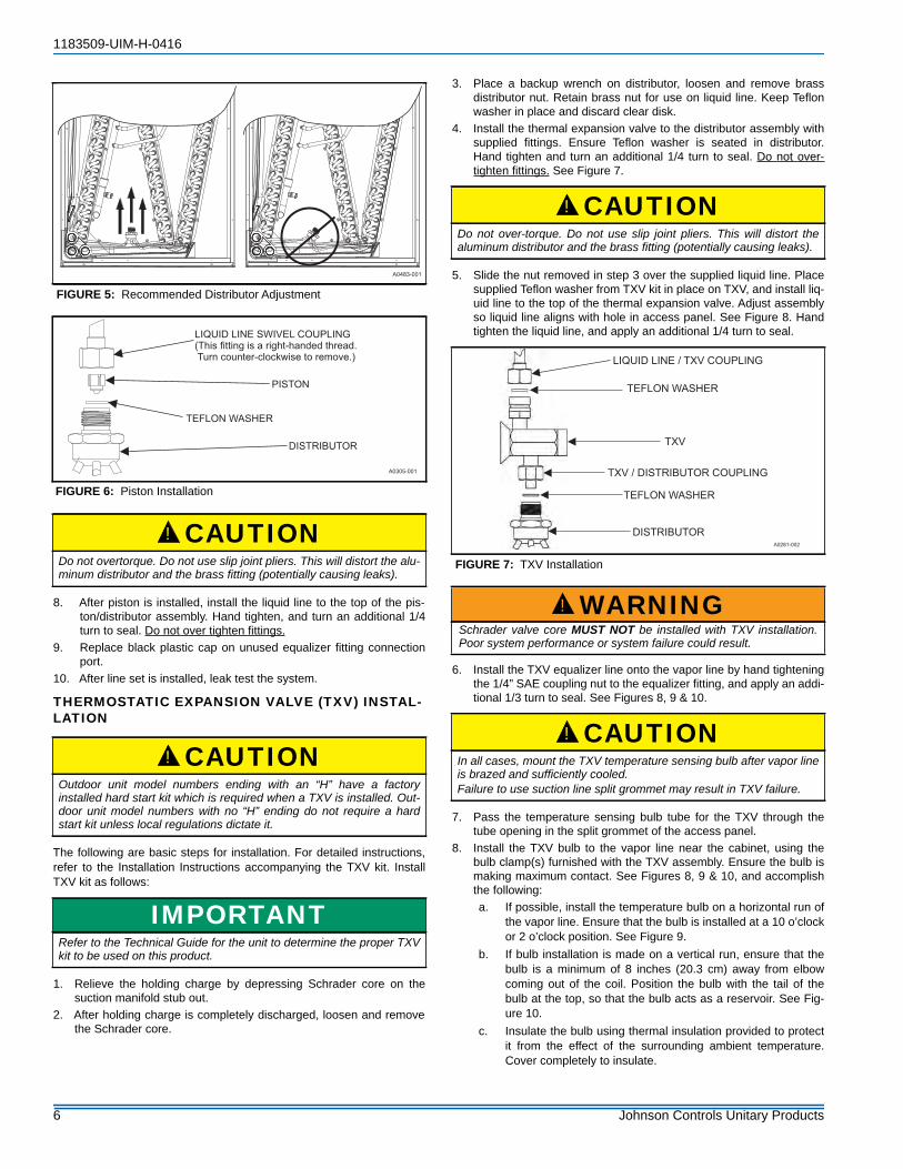
2. Distributor position must be adjusted to allow the preformed liquidline assembly to properly line up with the hole in the tubing accesspanel. Raise the distributor body approximately 2” toward the top ofthe coil or what would be the top of the coil if coil was in the upflowposition. See Figure 5. Adjust as necessary.
3. Install Schrader valve core supplied with the outdoor unit into theequalizer fitting connection port using a valve core tool.
4. Loosen and remove the liquid line connection nut and the sealingdisc from the distributor assembly. Note that the fitting has righthand threads.
5. Slide the nut over the liquid line to be installed, and discard theseal disc.
6. Install required size piston into the distributor. Refer to suppliedTabular Data Sheet for specific piston size and indoor coil matchup.
7. Verify that the Teflon washer is still in place in the distributor open-ing. See Figure 6.
CAUTIONDo not install any coil in a furnace which is to be operated during theheating season without attaching the refrigerant lines to the coil. Thecoil is under pressure which must be released to prevent excessivepressure build-up and possible coil damage.
NOTICELine set and indoor coil can be pressurized to 250 psig with dry nitro-gen and leak tested with a bubble type leak detector. Then releasethe nitrogen charge.Do not use the system refrigerant in the outdoor unit to purge or leaktest.
CAUTIONDo not connect manifold gauges unless trouble is suspected. Approx-imately 3/4 ounce of refrigerant will be lost each time a standard man-ifold gauge is connected.
WARNINGNever attempt to repair any brazed connections while the system isunder pressure. Personal injury could result.
!
!
!
CAUTIONCOIL UNDER PRESSURE.Verify that pressure has been released by depressing Schrader valvecore.The coil requires a metering device to be added. See outdoor unit documentation for correct TXV or piston to be used.
NOTICETo prevent moisture and contaminates from entering the system, thecoil should not be open to atmosphere for extended periods of time. Ifthe coil cannot be brazed into the refrigeration system during a rou-tine installation period, the ends should be temporarily closed orplugged. For a short term delay, use masking tape over the ends ofthe copper tubing to close the tube from the air. For a longer termdelay, use plugs or caps. There is no need to purge the coil if this pro-cedure is followed.
WARNINGFailure to install Schrader Valve Core in the vapor line equalizer con-nection port for piston applications could result in total refrigerant lossof the system!
!
!
Johnson Controls Unitary Products 5
1183509-UIM-H-0416
8. After piston is installed, install the liquid line to the top of the pis-ton/distributor assembly. Hand tighten, and turn an additional 1/4turn to seal. Do not over tighten fittings.
9. Replace black plastic cap on unused equalizer fitting connectionport.
10. After line set is installed, leak test the system.
THERMOSTATIC EXPANSION VALVE (TXV) INSTAL-LATION
The following are basic steps for installation. For detailed instructions,refer to the Installation Instructions accompanying the TXV kit. InstallTXV kit as follows:
1. Relieve the holding charge by depressing Schrader core on thesuction manifold stub out.
2. After holding charge is completely discharged, loosen and removethe Schrader core.
3. Place a backup wrench on distributor, loosen and remove brassdistributor nut. Retain brass nut for use on liquid line. Keep Teflonwasher in place and discard clear disk.
4. Install the thermal expansion valve to the distributor assembly withsupplied fittings. Ensure Teflon washer is seated in distributor.Hand tighten and turn an additional 1/4 turn to seal. Do not over-tighten fittings. See Figure 7.
5. Slide the nut removed in step 3 over the supplied liquid line. Placesupplied Teflon washer from TXV kit in place on TXV, and install liq-uid line to the top of the thermal expansion valve. Adjust assemblyso liquid line aligns with hole in access panel. See Figure 8. Handtighten the liquid line, and apply an additional 1/4 turn to seal.
6. Install the TXV equalizer line onto the vapor line by hand tighteningthe 1/4” SAE coupling nut to the equalizer fitting, and apply an addi-tional 1/3 turn to seal. See Figures 8, 9 & 10.
7. Pass the temperature sensing bulb tube for the TXV through thetube opening in the split grommet of the access panel.
8. Install the TXV bulb to the vapor line near the cabinet, using thebulb clamp(s) furnished with the TXV assembly. Ensure the bulb ismaking maximum contact. See Figures 8, 9 & 10, and accomplishthe following:a. If possible, install the temperature bulb on a horizontal run of
the vapor line. Ensure that the bulb is installed at a 10 o’clockor 2 o’clock position. See Figure 9.
b. If bulb installation is made on a vertical run, ensure that thebulb is a minimum of 8 inches (20.3 cm) away from elbowcoming out of the coil. Position the bulb with the tail of thebulb at the top, so that the bulb acts as a reservoir. See Fig-ure 10.
c. Insulate the bulb using thermal insulation provided to protectit from the effect of the surrounding ambient temperature.Cover completely to insulate.
FIGURE 5: Recommended Distributor Adjustment
FIGURE 6: Piston Installation
CAUTIONDo not overtorque. Do not use slip joint pliers. This will distort the alu-minum distributor and the brass fitting (potentially causing leaks).
CAUTIONOutdoor unit model numbers ending with an “H” have a factoryinstalled hard start kit which is required when a TXV is installed. Out-door unit model numbers with no “H” ending do not require a hardstart kit unless local regulations dictate it.
IMPORTANTRefer to the Technical Guide for the unit to determine the proper TXVkit to be used on this product.
A0305-001
DISTRIBUTOR
PISTON
LIQUID LINE SWIVEL COUPLING
(This fitting is a right-handed thread.
Turn counter-clockwise to remove.)
TEFLON WASHER
!
!
CAUTIONDo not over-torque. Do not use slip joint pliers. This will distort thealuminum distributor and the brass fitting (potentially causing leaks).
FIGURE 7: TXV Installation
WARNINGSchrader valve core MUST NOT be installed with TXV installation.Poor system performance or system failure could result.
CAUTIONIn all cases, mount the TXV temperature sensing bulb after vapor lineis brazed and sufficiently cooled.Failure to use suction line split grommet may result in TXV failure.
!
TXV / DISTRIBUTOR COUPLING
LIQUID LINE / TXV COUPLING
TEFLON WASHER
TXV
TEFLON WASHER
DISTRIBUTOR
A0281-002
!
!
6 Johnson Controls Unitary Products

1183509-UIM-H-0416
9. After line set is installed, leak test the system.
SECTION V: EVACUATIONIt will be necessary to evacuate the system to 500 microns or less. If aleak is suspected, leak test with dry nitrogen to locate the leak. Repairthe leak and test again.To verify that the system has no leaks, simply close the valve to thevacuum pump suction to isolate the pump and hold the system undervacuum. Watch the micron gauge for a few minutes. If the microngauge indicates a steady and continuous rise, it’s an indication of aleak. If the gauge shows a rise, then levels off after a few minutes andremains fairly constant, it’s an indication that the system is leak free butstill contains moisture and may require further evacuation if the readingis above 500 microns.
SECTION VI: SYSTEM CHARGE
The factory charge in the outdoor unit includes enough charge for theunit, a 15 ft. (4.6 m) line set, and the smallest indoor coil match-up.Some indoor coil matches may require additional charge. See tabulardata sheet provided in unit literature packet for charge requirements.
The “TOTAL SYSTEM CHARGE” must be permanently stamped on theunit data plate.TOTAL SYSTEM CHARGE is determined as follows:1. Determine the Base Charge shipped in the outdoor unit from the
Tabular Data Sheet included with the outdoor unit.2. Determine the charge adder for the matched indoor unit from the
Tabular Data Sheet included with the outdoor unit.3. If the lineset length is greater than 15 feet (4.6 m), calculate the
charge adder for actual lineset length using the Tabular DataSheet included with the outdoor unit.
4. Once the charge adders for matched indoor unit and for linesethave been weighed in, verify the system operation against thetemperatures and pressures in the Charging Chart for the outdoorunit. Locate Charging Charts on the outdoor unit and also in theService Application Data on www.upgnet.com. Follow the Subcoolor the Superheat charging procedure in the section below accord-ing to the type of indoor metering device in the system, and allowten minutes after each charge adjustment for the system operationto stabilize. Record the charge adjustment made to match theCharging Chart.
5. Verify that TOTAL SYSTEM CHARGE = Base Charge (asshipped) + charge adder for matched indoor unit + charge adderfor actual lineset length + charge adjustments to match ChargingChart.
6. Permanently stamp the unit data plate with the TOTAL SYSTEMCHARGE as defined above.
This method is to be used whenever additional refrigerant is requiredfor the system charge.
FIGURE 8: TXV Bulb and Equalizer line Installations
FIGURE 9: Proper Bulb Location
FIGURE 10: Vertical Temperature Bulb Orientation
TXV BULB
(Cover completely
with insulation.)
VAPOR LINE
OF LINE SETA0269-002
CLAMP
A
DETAIL A
TXV SENSING BULB
(Pass through split hole
in grommet.)
VAPOR
LINE
NUT
NUT
Bulb at
10 o’clock
position.
Bulb at
2 o’clock
position.
SCREW
SCREW
CLAMP
VAPOR LINE
OF LINE SET
A0378-002
CLAMP
TXV
TEMPERATURE
BULB
TAIL END UP
8” (20.3 cm)
NOTE:
Ensure bulb is on opposite
side of tubing bend plane.
NOTICEFor cold weather charging of the system at temperatures of 55°F orbelow, refer to the “Optional Cold Weather Charging” proceduresnear the end of SECTION VI: SYSTEM CHARGE.
CAUTIONDo not leave the system open to the atmosphere.
WARNINGDO NOT attempt to pump “Total System Charge” into micro channeloutdoor unit for maintenance, service, etc. This can cause damage tothe compressor and/or other components. The micro channel outdoorunit only has enough volume for the “Factory Charge,” not the “TotalSystem Charge.”
!
!
Johnson Controls Unitary Products 7

1183509-UIM-H-0416
If a calibrated charging cylinder or accurate weighing device is avail-able, add refrigerant accordingly. Otherwise, model-specific chargingcharts are provided on the access panel of the unit.
SUBCOOLING CHARGING METHOD - TXV INDOORThe outdoor unit comes equipped with subcooling charts optimized forthat particular unit. Please follow the instructions on the unit. If thoseinstructions are not readily available, follow the instructions below. 1. Set the system running in cooling mode by setting the thermostat
at least 6°F below the room temperature and operate system for atleast 10 – 15 minutes.
2. Refer to the technical guide for the recommended indoor airflowand verify it is correct (it should be 350- 400 SCFM per ton).
3. Measure and record the indoor wet bulb (WB) and the outdoorambient dry bulb (DB) temperature.
4. Using the charging chart located on the unit, find the intersectionof the indoor wet bulb and the outdoor dry bulb. This is the recom-mended liquid pressure (and subcooling value).
5. Measure and record the pressure at the liquid valve pressure portand compare to the value obtained in step 4.
6. Add charge if the measured liquid pressure is lower than the rec-ommended value. Remove / recover charge if the measured liquidpressure is above the recommended value.
Condenser subcooling is obtained by calculating the difference of thesaturated refrigerant temperature of the pressure measured at the liquidbase valve and the liquid tube temperature as measured at the liquidbase valve.Subcooling Temp. (TC) = Saturated Temp. (TS) – Liquid Temp. (T).
SUPERHEAT CHARGING METHOD - PISTON INDOOR1. Set the system running in cooling mode by setting the thermostat
at least 6°F below the room temperature and operate system for atleast 10 – 15 minutes.
2. Refer to the technical guide for the recommended airflow and ver-ify indoor airflow (it should be about 350-450 SCFM per ton).
3. Measure and record the outdoor ambient (DB) temperature andthe suction pressure at the suction service valve.
4. Using the charging chart located on the unit, find the intersectionof the outdoor ambient dry bulb and the suction pressure obtainedin step 3. This is the recommended suction tube temperature atthe service valve.
5. Measure and record the suction tube temperature at the servicevalve and compare to the recommended temperature obtained instep 4.
6. Add charge if the measured suction temperature in step 5 is abovethe recommended value. Remove / recover refrigerant if the mea-sured suction temperature is below the recommended value.
WARNINGIt is recommended to not attempt to pump more than the “FactoryCharge” and an additional 15 foot line charge into a tube and fin out-door unit for maintenance, service, etc. This can cause damage to thecompressor and/or other components.
CAUTIONRefrigerant charging should only be carried out by a qualified air con-ditioning contractor.
CAUTIONCompressor damage will occur if system is improperly charged. Onnew system installations, charge system per tabular data sheet forthe matched coil and follow guidelines in this instruction.
!
!
!
Example: The liquid pressure listed at the intersection of the indoor WB and the outdoor DB 320 psig. Pressure at the liquid valve is 305 psig. It would be necessary to add refrigerant to increase the liquid pressure to 320 psig.
CAUTIONIT IS UNLAWFUL TO KNOWINGLY VENT, RELEASE OR DIS-CHARGE REFRIGERANT INTO THE OPEN AIR DURING REPAIR,SERVICE, MAINTENANCE OR THE FINAL DISPOSAL OF THISUNIT.
Example: The suction tube temperature listed on the table at the intersection of the outdoor DB and the suction pressure is 63°F. Temperature of the suction tube at the service valve is 68°F. It would be necessary to add refrigerant to drop the suction tube temperature to 63°F.
!
TABLE 2: R-410A Saturation Properties
TEMP. °F PRESSURE PSIG TEMP. °F PRESSURE
PSIG TEMP. °F PRESSURE PSIG TEMP. °F PRESSURE
PSIG TEMP. °F PRESSURE PSIG
45 130 60 170 75 217 90 274 105 34146 132 61 173 76 221 91 278 106 34547 135 62 176 77 224 92 282 107 35048 137 63 179 78 228 93 287 108 35549 140 64 182 79 232 94 291 109 36050 142 65 185 80 235 95 295 110 36551 145 66 188 81 239 96 299 111 37052 147 67 191 82 243 97 304 112 37553 150 68 194 83 247 98 308 113 38054 153 69 197 84 250 99 313 114 38555 156 70 201 85 254 100 317 115 39156 158 71 204 86 258 101 322 116 39657 161 72 207 87 262 102 326. 117 40158 164 73 211 88 266 103 331 118 40759 167 74 214 89 270 104 336 119 412
8 Johnson Controls Unitary Products

1183509-UIM-H-0416
OPTIONAL COLD WEATHER CHARGING
1. Assemble the charging tent. 2. Slide charging tent over top of condenser unit.3. Position the door zipper over the lineset so charging tent sits
evenly on ground.4. Make sure distance around condenser inside of charging tent is
even for airflow.5. Stake down the edges of the charging tent cover to prevent the
unit fan from blowing the charging tent away.6. Start condenser.7. For better temperature measurement inside the charging tent, use
a thermocouple to monitor temperature readings. Locate the ther-mocouple monitor approximately 8-10 inches away from the coilguard and 2/3 the way above the bottom of the coil on the oppositeside from the control box.
8. Based on outdoor ambient temperature, begin adjusting windowsin order to achieve a stable temperature above 55°F inside tent.Note that the colder the outdoor ambient temperature is the fewerwindows need removal.
9. Use condenser charging chart. Verify that the outdoor ambienttemperature listed on the charging chart is the temperature insidethe charging tent.
10. Carefully adjust the charging tent windows until reaching thedesired temperature, and allow the unit to stabilize for a minimumof 15 minutes. Check the thermocouple to make sure the tempera-ture is still maintained at desired temperature. If the temperature isout of range, adjust the windows by opening or closing them.
11. Once the condition inside the charging tent is STABILIZED, followthe “System Charge” procedure to adjust charge in the unit.
12. Add or remove charge, and adjust windows to maintain thedesired temperature inside the tent.
SECTION VII: ELECTRICAL CONNECTIONSGENERAL INFORMATION & GROUNDINGThe control box cover is held in place with 3 screws (one screw in eachlower corner and one screw at the top center post). The control box canswing open by removing the screw from the center of each side of thecontrol box and allowing the control box to lower an inch or so into apivotal position.
The control box can then swing open from the left by rotating on theright side pivots for easy service of refrigeration components. If no wir-ing is in or routed through the control box, it can be removed from theunit by lifting slightly, tilting the top hinge out, and lifting the bottomhinge out. During the installation, it is recommended to route the lowvoltage wiring for the thermostat along the unit whip to help facilitate theswing away feature of the control box. Refer to Figure 11.
Check the electrical supply to be sure that it meets the values specifiedon the unit nameplate and wiring label. Power wiring, control (low voltage) wiring, disconnect switches and overcurrent protection must be supplied by the installer. Wire size should besized per NEC requirements.
The complete connection diagram and schematic wiring label is locatedon the inside surface of the unit service access panel.
FIELD CONNECTIONS POWER WIRING1. Install the proper size weatherproof disconnect switch outdoors
and within sight of the unit.2. Remove the screws at the top and sides of the corner cover. Slide
the control box cover down and remove from unit.3. Run power wiring from the disconnect switch to the unit.4. Route wires from disconnect through power wiring exit provided
and into the unit control box as shown in Figures 11, 12, 13 & 14.5. Install the proper size time-delay fuses or circuit breaker, and
make the power supply connections.
NOTICEFor better airflow, the size of the charging tent must be at least70"x70”x70” and must have some adjustable flaps or windows to con-trol the temperature inside the charging tent. The charging tent mustnot have a floor or floor covering. Be sure to follow the “SystemCharge” procedures from Section VI of this Installation Manual.
NOTICEA flexible electrical whip must be installed in order to use the swingaway function of the control box. Other type electrical whips requirethe wiring to be disconnected in order to swing the control box open.
FIGURE 11: Outdoor Unit Swing Away Control Box
CAUTIONAll field wiring must USE COPPER CONDUCTORS ONLY and be inaccordance with Local, National, Fire, Safety & Electrical Codes. Thisunit must be grounded with a separate ground wire in accordancewith the above codes.
A0336-001
HIGH VOLTAGE
ELECTRICAL WHIP
CONTROL BOX
(Swing away)
!
Johnson Controls Unitary Products 9

1183509-UIM-H-0416
FIELD CONNECTIONS CONTROL WIRING1. Route low voltage wiring into bottom of control box as shown in
Figure 12, 13 or 14. Make low voltage wiring connections insidethe low voltage box per Figure 15.
2. The complete connection diagram and schematic wiring label islocated on the inside surface of the unit service access panel.
3. Replace the control box cover removed in Step 2 of the FIELDCONNECTINS POWER WIRING procedures.
4. All field wiring to be in accordance with national electrical codes(NEC) and/or local-city codes.
5. Mount the thermostat about 5 ft. above the floor, where it will beexposed to normal room air circulation. Do not place it on an out-side wall or where it is exposed to the radiant effect from exposedglass or appliances, drafts from outside doors or supply air grilles.
6. Route the 24-volt control wiring (NEC Class 2) from the outdoorunit to the indoor unit and thermostat.
FIGURE 12: Outdoor Unit Control Box (Single Phase - Smaller Base)
FIGURE 13: Outdoor Unit Control Box (Single Phase - Larger Base)
FIGURE 14: Outdoor Unit Control Box (Three Phase)
NOTICEA Start Assist Kit is available and recommended for long line setapplications or in areas of known low voltage problems. The kit maybe required when a TXV is used (reference the Tabular Data Sheet todetermine if applicable).
NOTICETo eliminate erratic operation, seal the hole in the wall at the thermo-stat with permagum or equivalent to prevent air drafts affecting theoperation of in the thermostat.
10 Johnson Controls Unitary Products

1183509-UIM-H-0416
For additional connection diagrams for all UPG equipment refer to “Low Voltage System Wiring” document available online at www.upgnet.com inthe Product Catalog Section.
FIGURE 15: Typical Field Wiring (Air Handler / Electrical Heat) (Single-Phase)
ALL FIELD WIRING TO BE IN ACCORDANCE WITH ELECTRIC CODE (NEC) AND/OR LOCAL CODES
POWER WIRING
CONTACTOR
TERMINALS
COILGND.
LUG
C Y R G W
Y R G W
POWER WIRING
CONTROL WIRING
FACTORY WIRING24 VOLT CONTROL WIRING
MINIMUM 18 GA. WIRE
(NEC CLASS 2)
FURNACE OR AIR HANDLER TERMINAL BLOCK
ROOM THERMOSTATCONDENSING UNIT
ALL OUTDOOR WIRING MUST BE WEATHERPROOF. USE COPPER CONDUCTORS ONLY.
Terminal W is only
required on systems
with heat.
*
*
A0158-001
FIGURE 16: Thermostat Chart - PSC Air Handler with Single Stage Air Conditioner
A0288-001
Johnson Controls Unitary Products 11

1183509-UIM-H-0416
SECTION VIII: INSTRUCTING THE OWNERAssist owner with processing warranty cards and/or online registration.Review Owners Guide and provide a copy to the owner and guidanceon proper operation and maintenance. Instruct the owner or the opera-tor how to start, stop and adjust temperature setting.When applicable, instruct the owner that the compressor is equippedwith a crankcase heater to prevent the migration of refrigerant to thecompressor during the OFF cycle. The heater is energized only whenthe unit is not running. If the main switch is disconnected for long peri-ods of shut down, do not attempt to start the unit until 8 hours after theswitch has been connected. This will allow sufficient time for all liquidrefrigerant to be driven out of the compressor.The installer should also instruct the owner on proper operation andmaintenance of all other system components.
MAINTENANCE1. Dirt should not be allowed to accumulate on the outdoor coils or
other parts in the air circuit. Clean as often as necessary to keepthe unit clean. Use a brush, vacuum cleaner attachment, or othersuitable means.
2. The outdoor fan motor is permanently lubricated and does notrequire periodic oiling.
3. If the coil needs to be cleaned, use clean water to wash dust, dirt,and debris from outdoor condensing coil.
4. Refer to the furnace or air handler instructions for filter and blowermotor maintenance.
5. The indoor coil and drain pan should be inspected and cleaned regularly to prevent odors and assure proper drainage.
FIGURE 17: Thermostat Chart - Single Stage PSC Furnace with Single Stage Air Conditioner
A0289-001
NOTICEDO NOT use coil cleaners to clean outdoor condensing coil. Cleanerscontaining HF –, hydroxides, chlorides, and sulfates can greatlyreduce the lifetime of the micro channel coil.
CAUTIONIT IS UNLAWFUL TO KNOWINGLY VENT, RELEASE OR DIS-CHARGE REFRIGERANT INTO THE OPEN AIR DURING REPAIR,SERVICE, MAINTENANCE OR THE FINAL DISPOSAL OF THISUNIT.
!
12 Johnson Controls Unitary Products

1183509-UIM-H-0416
SECTION IX: WIRING DIAGRAM
FIGURE 18: Wiring Diagram - Single Phase 13 & 14 Seer
C
R
S
S
C
R
FANMOTOR
GND
5
2
1
C
HERM
FAN
HIGH VOLTAGE FACTORY WIRINGLOW VOLTAGE FACTORY WIRINGOPTIONAL WIRINGFIELD WIRING, LINE VOLTAGE
DU
AL
CA
PA
CIT
OR
HPS
SR
SC
JUNCTIONBOX
TURN OFF ELECTRICAL POWER BEFORESERVICING TOPREVENT POSSIBLE DAMAGETO THE EQUIPMENT AND POSSIBLEPERSONAL INJURY. TO PREVENT ELECTRICAL SHOCK OPENREMOTE DISCONNECT SO ELECTRICALSUPPLY TO AIR CONDITIONER IS SHUT OFF. COMPONENTS SHOWN IN DASHED LINES ARE OPTIONAL. DUAL CAPACITOR SHOWN SEPARATE CAPACITORS MAY BE USED ON ACTUAL UNIT. WIRING MUST CONFORM TO NATIONAL AND LOCAL CODES. IF ANY OF THE ORIGINAL WIRE SUPPLIED WITH THIS UNIT MUST BE REPLACED, IT MUST BE REPLACED WITH TYPE 105°C. THERMOPLASTIC OR ITS EQUIVALENT. WHERE POWER SUPPLY HAS ONE (1) 230 VOLT CONDUCTOR AND ONE (1) NEUTRAL CONDUCTOR, CONNECT L2 OF CONTACTOR TO NEUTRAL.
GND.24 VAC
CONTROLCIRCUIT
(20 VA MIN.)
208-230 VAC 60 Hz 1 PHASE SUPPLY220-240 VAC 50 Hz 1 PHASE SUPPLY
USECOPPER
CONDUCTORSONLY
CONTACTOR
GND.LUG
HS
CCH
HPS - HIGH PRESSURE SWITCHLPS - LOW PRESSURE SWITCHCCH - CRANKCASE HEATERHS - HEATER SWITCHSR - START RELAYSC - START CAPACITORCC - CONTACTOR COIL
DANGER - SHOCK HAZARD
CAUTION
1
2
3
4
5
BLK
BLK
BLK
BR
N
BLK
RE
D
RED
BR
N
RE
D
RE
D
GRN
BRN
BRN
RED
YEL
RE
D
BLU
BLK
BLK
BLK
T1 T2
L1 L2
CC
COMPRESSORMOTOR
BLK
2
5
1
1
1
1183564-UWD-B-0215
LPS1
BLU
YE
L/P
NK
OR
YE
LY
EL/
PN
KO
R Y
EL
Johnson Controls Unitary Products 13

1183509-UIM-H-0416
FIGURE 19: Wiring Diagram - Single Phase 17 Seer
C
R
S
5
2
1
C
HERM
FAN
HIGH VOLTAGE FACTORY WIRINGLOW VOLTAGE FACTORY WIRINGOPTIONAL WIRINGFIELD WIRING, LINE VOLTAGE
DU
AL
CA
PA
CIT
OR
HPS
SR
SC
JUNCTIONBOX
DANGER - SHOCK HAZARD TURN OFF ELECTRICAL POWER BEFORESERVICING TO PREVENT POSSIBLE DAMAGETO THE EQUIPMENT AND POSSIBLEPERSONAL INJURY. TO PREVENT ELECTRICAL SHOCK OPENREMOTE DISCONNECT SO ELECTRICALSUPPLY TO AIR CONDITIONER IS SHUT OFF. COMPONENTS SHOWN IN DASHED LINES ARE OPTIONAL. DUAL CAPACITOR SHOWN SEPARATE CAPACITORS MAY BE USED ON ACTUAL UNIT. WIRING MUST CONFORM TO NATIONAL AND LOCAL CODES. IF ANY OF THE ORIGINAL WIRE SUPPLIED WITH THIS UNIT MUST BE REPLACED, IT MUST BE REPLACED WITH TYPE 105°C. THERMOPLASTIC OR ITS EQUIVALENT. WHERE POWER SUPPLY HAS ONE (1) 230 VOLT CONDUCTOR AND ONE (1) NEUTRAL CONDUCTOR, CONNECT L2 OF CONTACTOR TO NEUTRAL. HPS - HIGH PRESSURE SWITCHLPS - LOW PRESSURE SWITCHCCH - CRANKCASE HEATERHS - HEATER SWITCHSR - START RELAYSC - START CAPACITORCC - CONTACTOR COIL
GND.
24 VACCONTROLCIRCUIT
(20 VA MIN.)
208-230 VAC 60 Hz 1 PHASE SUPPLY220-240 VAC 50 Hz 1 PHASE SUPPLY
USECOPPER
CONDUCTORSONLY
CONTACTORGND.LUG
HS
CCH
CAUTION
1
2
3
4
5
BLK
BLK
BLK
BR
N
RE
D
RE
D
BRN
RED
YEL
RE
D
BLUBLK
BLK
BLK
T1 T2
L1 L2
CC
COMPRESSORMOTOR
BLK
2
5
1
1
1
5160254-UWD-B-0116
LPS1
BLU
YE
L/P
NK
OR
YE
LY
EL/
PN
KO
R Y
EL
SC
R
FAN MOTOR
63 5
PLU
G
421
GR
N/Y
EL
BLU
RED
BLK
BLK
VSCONTROL
BLU
YE
L O
R W
HT
OR
OR
G O
R P
UR
BLK
RED
BLU
SLV
SLV
RE
D O
RB
RN
RE
D O
R B
RN
14 Johnson Controls Unitary Products

1183509-UIM-H-0416
SECTION X: START UP SHEET
Air Conditioning and Heating Start-Up Sheet Proper start-up is critical to customer comfort and equipment longevity
Name Address
City State or Province Zip or Postal Code
Indoor Unit Model # Indoor Unit Serial #
Indoor Coil Model # Indoor Coil Serial #
Upflow Downflow Horizontal Left Horizontal Right
Unit is level
Venting system properly sized, within the limitations of the charts in the installation instructions.
Condensate drain for indoor coil properly connected
Filter Type
Intake Size
Exhaust Size
# of 90 Degree Ells # 0f 45 Degree Ells Length
Length # 0f 45 Degree Ells# of 90 Degree Ells
Polarity is correct (120vac indoor units) black is L1 (hot), white is N (neutral)Ground wire is connected
Indoor unit (volts AC)
Low voltage values: "R" and "C" at Indoor unit control board (volts AC)
Thermostat Type Other System Equipment and Accessories
Owner Information
Equipment Data
Venting (if applicable)
Electrical: Line Voltage
Outdoor Unit Model # Outdoor Unit Serial #
Filter, Thermostat, Accessories
Filter Location(s)
Connections -- Per Installation Instructions and Local Codes
Gas piping is connected (if applicable)
Supply plenum and return ducts are connected and sealed
Filter Size
Vent system is connected (if applicable)
Thermostat wiring complete
Heat anticipator is set to the recommended value listed in the Installation Instructions
Electrical: Low Voltage
Technician Performing Start-Up Installing Contractor Name
Start-Up Date
Condensate drain for furnace (if applicable)
Refrigerant piping complete and leak tested
Outdoor unit (volts AC) Overcurrent Protection Breaker / Fuses Amperes
"R" and "C" Outdoor unit control board (volts AC)
Heating Set-Up Natural Gas LP Gas (Requires LP Conversion Kit)Electric Air Handler
LP Gas Conversion Kit Part # Used
LP Kit Installed By
Inlet Gas Pressure (in. w.c.")
Calculated input in btuh - clock the gas meter (Nat Gas Only)
Manifold Gas Pressure (in. w.c.")
Heating Type
Heat anticipator recommended value
Electric Heat Kit Part # (if applicable) KW installed
Continued on next Page
Rated BTU/H (furnaces)
Print Form Reset Form
Johnson Controls Unitary Products 15

Supply static after indoor coil (in w.c.")
Return Static (in w.c.") before filter
Total External Static Pressure
Installation debris disposed of and indoor and outdoor areas cleaned up?
Explain operation of system to equipment owner
Low
1 2
Medium Low Medium
3 4
Medium High High
5
A B DC
A B C D
Explain the importance of regular filter replacement and equipment maintenance
Air Side: System Total External Static Pressure
Owner Education
Supply static before indoor coil (in w.c.")
Return Static (in w.c.") after filter (furnace side)
Cooling Indoor
Blower Set-Up
Clean Up
Provide owner with the owner's manual
Explain thermostat use and programming (if applicable) to owner
Cycle Test
Operate the unit through several heating cycles (if applicable) from the thermostat, noting and correcting any problems
Operate the unit through continuous fan cycles from the thermostat, noting and correcting any problems
Operate the unit through a cooling cycles, noting and correcting any problems
COOL
ADJUSTECM
X-13
PSC
A B C DDELAY
Heating Indoor
Blower Set-Up
ECM
X-13
PSC
A
1 5
High
2 3 4
Low Medium Low Medium Medium
High
DB C
Temperature Rise
Maximum Rated ESP (in w.c.")
HEAT
Refrigerant Charge and Metering Device
TXV Fixed OrificeR-22 R-410A
Oz.
# 45s# Elbows
Additional Lineset Length Adder per foot - lbs.
Total Added - lbs. Oz.
Comments Section
Liquid Line Temp Low Side PressureSuction Line TempHigh Side Pressure
Subcooling Superheat
Orifice Size
TXV #
Return Air: Dry Bulb Supply Air: Dry Bulb Temperature Drop Outside Air: Dry Bulb Wet Bulb
Supply Air: Dry Bulb Wet Bulb Return Air: Dry Bulb
Subject to change without notice. Published in U.S.A. 1183509-UIM-H-0416Copyright © 2016 by Johnson Controls, Inc. All rights reserved. Supersedes: 1183509-UIM-G-0316
York International Corp.5005 York Drive
Norman, OK 73069