Embed Size (px)
Citation preview

REVISED 4/05/11
INSTALLATION MANUAL
AppLIcATION:
240 gph @ 45psi (FA D11 240g)
Cummins 5.9L 12 ValveWith p7100 injection pump
1994-1998

3
Dear Valued Customer,
“Made in the USA” is not just a slogan at FASS; it‟s what we live by! FASS is not only assembled in
the USA but 98%+ of the FASS product is manufactured in the USA, helping to employ Americans and
strengthen America. At FASS, we scrutinize our suppliers and demand the highest quality American-made
components. However, this does come at a price, which is one of the main reasons FASS products are more
expensive than the competition. Remember price does not dictate quality but quality does dictate price! Here
at FASS, we believe it‟s worth the commitment and will continue this practice to support America! Our com-
petition is doing exactly the opposite by using foreign-made components.
Building extremely “High-Quality” fuel products is our business. We concentrate all of our efforts in
this arena. No one else is as specialized as FASS in what we do! This is one of the ingredients to insure you
are running with the “Highest-Quality” fuel system in the world! We have implemented very rigorous testing
procedures to provide the “Highest Quality” we have become known for. Not only is our product superior, but
customer satisfaction is #1 at FASS. It is our goal to provide the best service possible. Our confidence is evi-
dent in the products we make as each product is backed by an industry leading warranty!
Our R & D department, in conjunction with our Dealer Support department, is continually searching
for ways to improve quality, expand our product line, and provide superb support to our network of dealers so
our customers‟ needs and expectations will be exceeded.
To help insure you receive the proper system and customer support at the local level, FASS has a VIP
and Authorized Dealer network representing FASS products. This is one reason you must purchase through a
dealer to comply with our warranty policies. If you do not, there is no warranty! We recommend you go to
www.FASSride.com, click “Find A Dealer”, put in their ZIP code, select the type of dealer, and see if the com-
pany you purchased from is listed. If they are not, put their phone number in the field below the ZIP code field
to see if they are listed. Below these two fields is a list of “Terminated/Unauthorized” dealers. You may want
to review this list. If the company is not listed or is on the “Terminated/Unauthorized” list, we suggest you
return the product immediately to that dealer and call FASS. We‟ll recommend you to the nearest dealer.
VERY IMPORTANT: Make sure to fill out your product registration form and return the original form
to FASS Fuel Systems within 30 days of purchase accompanied with a copy of the purchase receipt. Comply-
ing with these guidelines will qualify you for the Extended Warranty!
See the Owner‟s Manual for full Limitation of Warranty. In the event that the buyer does not agree
with this agreement: the buyer may promptly return this product, in a new and unused condition, with a dated
receipt, to the place of purchase within thirty (30) days from date of purchase for a full refund less shipping.
The installation of this product indicates that the buyer has read and understands the Limitation of
Warranty agreement and accepts its terms and conditions.

4
STEPS TO CUSTOMER SATISFACTION
We expect every FASS System to exceed your expectation. Customer satisfaction, your satisfac-
tion, is the all-important ingredient for success to our business, as it is in any other.
Normally, technical issues can be resolved by your dealer‟s service department, as they can usual-
ly inspect the situation physically. If you‟re not satisfied with the dealership‟s response you can either
email or call FASS.
Email [email protected] with the following information:
Your Name, address and daytime phone number
Model and Serial Number (Not Motor Number)
Example: Model – Fuel Pump (Adjustable) Serial: 00125966
Vin Number of Vehicle
Date of purchase
Nature of Problem
Call customer service; to better assist you please gather the following information before calling:
Model and Serial Number (Not Motor Number)
Example: Model – Fuel Pump (Adjustable) Serial: 00125966
Vin Number of Vehicle
Date of purchase
Serial #
Serial #

5
WARNING!!
Installing the improper FASS Fuel Pump can cause severe engine damage.
This installation manual applies to the FA D11 240G contained in the same package. The serial number on
the installation/owners manual package should match the serial number on the outside of the box. If it
doesn’t, call your dealer.
This FA D11 240G applies to this application:
Recommendation: FA D11 240G – Dodge Cummins Truck 1994-1998 (12 Valve Cummins
engine), with Extreme horsepower modifications.
SAFETY GUIDELINES AND WARNINGS!
TIP! Flush and clean all brass fittings and fuel line free from debris.
WARNING! SECURE VEHICLE FROM ROLLING!
WARNING! Use care not to drill into any electrical wires, air lines or other damageable compo-
nents when drilling.
WARNING! Consult vehicle manufacturer‟s instructions concerning the electrical system before
attempting any electrical connections.
CAUTION: Wear safety glasses when operating power tools such as drills and grinders or when
using a punch or chisel.
CAUTION: Properly secure lines to prevent chaffing.
Read all instructions before starting installation of this product!

6
WARNINGS!!
Use caution when preparing or installing items in fluid connectivity with the “T” port, as debris can lock up
the motor. This also includes applying thread tape over the threads “ONLY”, not blocking or obstructing any
path that fuel travels. If the motor does lock up from debris, call FASS for technical assistance. 100% of the
FASS Fuel Pumps are vigorously tested, which includes (but not limited to) wet testing for pressure, amps,
flow, & including total all around performance before being shipped.
For the same reason as mentioned above, the FASS Pump must be protected by a fuel filter as debris is pre-
sent in diesel fuel and fuel systems. Use the inline fuel filter, or equivalent, which accompanied your FASS
Fuel Pump.

7
INSTALLATION MANUAL
The installation of the FASS HIGH PERFORMANCE FUEL PUMP can be relatively simple
when the following steps are followed.
1. Inventory the package components completely. Notify the place of purchase immedi-
ately of any parts missing or damaged.
2. We have invested many hours into the development of the installation manual to simplify
the installation of the FASS Fuel Pumps. Please read the installation manual completely
before attempting installation. Understand how the system operates and installation rec-
ommendations before beginning installation. Most of the questions that you will have will
be answered in the manual. If you have a question please review the installation manual.
3. The installation recommendations contained herein are suggested installation guidelines
only. Each installation can and may vary considerably because of the many options and
accessories available to the truck market.
Installation personnel should use good judgment and common sense when installing the
FASS High Performance Fuel Pump.
If any installation procedure is uncertain, contact FASS technical support.
Due to training, communication, and our relationship with our authorized dealers, we recom-
mend an authorized FASS Fuel Systems dealer for the installation. They are prepared to in-
stall the FASS fuel pumps with the most efficiency. If a situation/problem arises during the
installation, they are the most prepared for that situation/problem. It may take more time for
an unauthorized shop to address the situation/problem. We are not responsible for any instal-
lation mistakes.

8
Adjustable Fuel pump Series
240 GPH
45 PSI Approximately
A fuel pressure gauge is highly recommended to identify fuel filter life and to prevent engine damage!
Installation
Step 1: Install Electrical Harness
Step 2: Prepare Fuel Tank
Step 3: Mount Fuel System
Step 4: Install Fuel Line
Step 5: Check/Setting Pressure
Step 6: Review Installation
“E”
To Engines
„T‟
Fuel Inlet Port
Boost
Compensation
Port
Fuel Pressure Port
Adjustment Lock Nut
Set screw

9
CONTENTS:
FL-1002 x 14‟ FF 3248 THB-1001 &
BHB-1001
(1/4)” - 20 x 1.75” .25 Nuts .25 Lock Washers (1/4)” - 20 x 3.5”
WH-1005
MP-9037
PL-1004 10-300 PL-1005 1/2” Plug DIPF-1004
Ring Terminal NP-1001 RS-1002 PL-2003
BHF-1002 LW-1001 BHN-1001 ST-1005P
14” x 5/8”
OR-223
HC-1001
WE-1001 Fuse Tap Flag Terminal
10
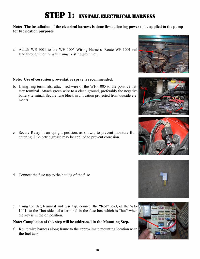
Step 1: Install Electrical Harness
a. Attach WE-1001 to the WH-1005 Wiring Harness. Route WE-1001 red
lead through the fire wall using existing grommet.
c. Secure Relay in an upright position, as shown, to prevent moisture from
entering. Di-electric grease may be applied to prevent corrosion.
b. Using ring terminals, attach red wire of the WH-1005 to the positive bat-
tery terminal. Attach green wire to a clean ground, preferably the negative
battery terminal. Secure fuse block in a location protected from outside ele-
ments.
Note: Use of corrosion preventative spray is recommended.
Neg.
Pos.
Fuse
Note: The installation of the electrical harness is done first, allowing power to be applied to the pump
for lubrication purposes.
d. Connect the fuse tap to the hot leg of the fuse.
e. Using the flag terminal and fuse tap, connect the “Red” lead, of the WE-
1001, to the “hot side” of a terminal in the fuse box which is “hot” when
the key is in the on position.
Note: Completion of this step will be addressed in the Mounting Step.
f. Route wire harness along frame to the approximate mounting location near
the fuel tank.

11
Step 2: Prepare Fuel Tank
b. Disconnect the factory suction and return line. The factory lines are removed
by pressing in on the two tabs located in the connecting fuel line. Keep the tab
on the factory return.
c. Disconnect the factory electrical harness on top of the fuel tank.
d. With the fuel tank empty of fuel, remove it from the vehicle.
e. Clean the fuel module area then remove the lock ring on the top of the fuel
tank.
f. Once the lock ring is removed, remove pick up module from fuel tank. Be
careful not to bend the fuel sending arm.
Very Important: Before removing the fuel tank identify “ALL” areas of clear-
ance between the tank and bed to install the draw tube assembly.
The closer the suction tube is placed to the center of the fuel tank, front to back
and left to right, the more usable fuel there will be!
Helpful Hints: If more space is required to access the top of the fuel tank, loosen
the strap nuts to the end of the stud. This will gain you about 3” more working
room.
Some of the photo‟s are of a different application, procedures are the same.
a. Remove the filler neck and overflow tubes from the truck by loosening the
clamps at both ends.
g. Assemble the BHF-1002 with the PL-1004 in port “S” using thread tape, the
1/2” plug in port “R” along with pushing the ST-1005P onto the barb portion
of the BHF-1002. Insert O-ring into groove. Torque to 40ft/lbs.

12
STEP 2: Prepare Fuel Tank, Continued
n. Attach fuel line to Push-Lok fitting. Remember to oil the fitting and fuel line.
Cap or plug factory suction port.
k. Place the bulk head assembly into the drilled hole, take measurements so the
bottom of the suction tube is only 1/8” (no more than 2 quarters stacked) from
the bottom of the fuel tank. Using a razor knife, make multiple cuts to insure
proper length, it is easy to shave the suction tube with the razor.
It is more efficient to cut the tube too long and then correct to proper
length than it would be to cut too short.
l. With proper length being obtained place the assembly into the drilled hole se-
curing the assembly using the lock washer & nut. Tighten Nut. Loctite may be
applied to the threads of the BHF-1002 for added insurance.
i. Drill a 1 1/2” hole, catching all debris. De-bur hole and remove any missed
debris in the fuel tank.
j. VERY IMPORTANT: Support fuel tank on both ends allowing the natural for-
mation of the tank to take place. Failure to perform this step can and will create
an issue with less usable fuel!
m. Carefully reinstall install pick up module making sure the fuel sending arm is
not obstructed by the suction tube. Reinstall factory lock ring.
h. Before drilling marked location, clean area of debris. Using the photo double
check area selected for any interference including the fuel level arm.

13
p. Connect factory wire harness to the fuel module along with the factory return
fuel line.
STEP 2: Prepare Fuel Tank, Continued
o. Route fuel line over the frame rail while reinstalling the fuel tank. Torque tank
hanger bolts to proper specifications.
q. Reattach filler neck and clamps.
FASS harness

14
c. Using thread tape, install the two 10-300 into the “T” & “E” ports.
Torque to 40 ft./lbs.
VERY IMPORTANT: REMEMBERING THE POSITION OF THE “T” PORT,
THERE IS A SMALL WEEP HOLE IN THE BASE DIRECTLY NEXT TO THE
ELECTRIC MOTOR, THIS HOLE MUST AIM DIRECTLY TO THE GROUND!! IM-
PROPER INSTALLATION OF THE PUMP CAN CAUSE PREMATURE WEAR
AND VOID MANUFACTURES WARRANTY.
d. Connect the male end of the wire harness to the female electrical connector
on the FASS pump. Turn key to the “On” position. With the FASS pump
on, squirt a liberal amount of WD-40 or other lubricant into the “T” port.
This procedure will “wet” the Gerotor and allow for better suction during
initial priming.
e. Using the bottom portion of the mounting bracket and the four ¼” – 20 x
1 ¾” bolts, mount the fuel pump mount the pump so the port labeled “T”
is facing the rear of the truck. Torque the 4 ¼ - 20x 1 ¾” bolts to 110 inch
pounds.
Note: Use of Anti-seize compound is highly recommended.
b. Install the two ¼”-20 x 3 1/4” bolts, nuts and lock washers and THB-
1001.
a. Position system to mounting location, drivers side bed rail in front of the
axle. Use the mounting template, located at the rear of this manual, to help
mark the mounting location. Drill two ¼” holes.
Note: Place a rubber spacer between the hanger bracket and bed rail and
the other rubber spacer on the opposite side between the bed rail and NP-
1001 nut plate.
Step 3: Mount FASS Fuel Pump
Note: the mounting bracket may be mounted on either side.

15
STEP 4: Installing Fuel Line
NOTE: Hose clamps are not recommended for push lock fittings. They will hold up to 300psi!
Caution: Do Not use sealant on AN fittings. Only use sealant on threads installed into pump assembly.
a. Route fuel line to the suction port on the FASS pump labeled “T”.
Cut the fuel line. Insert PL-1005 into fuel line using oil. Attach to 10
-300 in „T‟ port. Torque to 18 ft./lbs.
T
c. Insert PL-1005 into fuel line. Attach to 10-300 located in the port
labeled “E”. Use oil. Torque to 18 ft./lbs. Route this line to the inlet
port of the factory filter housing.
E
b. Install in-line fuel filter in an accessible location in the suction line
using the HC-1001‟s. Make sure the fuel flows in the direction of the
arrow on the canister.
d. Measure and cut fuel line. Insert PL-2003 90° Push-Lok fitting using
oil.
f. Disconnect factory fuel line and injector return line from inlet side of
the factory fuel filter and install the DIPF-1003. Torque to 18 ft./lbs.
Note: Use oil on fittings and inside fuel line when installing Push-Lok fittings.

16
h. Attach the PL-2003 to DIPF-1003. Torque to 18 ft./lbs.
i. Remove banjo bolt connecting the outlet line of the factory fuel filter.
This is the line in front of the inlet line removed in step f.
j. Move the injector return line from step f and stack on top of the outlet
line of the factory fuel filter. Light bending will be required, be very
careful not to kink or crack this fuel line. Install the Banjo Bolt removed
in step f. Torque to 18 ft./lbs.

17
The port with 1/8” Allen plug marked with the letter “P” is a gauge port.
To adjust the pressure follow these procedures:
With the pump running –
Loosen the lock nut
Turn the adjustment screw clock wise to increase pressure and counter clock wise to de-
crease pressure.
Once desired fuel pressure is obtained, tighten lock nut.
Warning: Exceeding factory fuel pressure may result in severe engine damage. Consult with en-
gine manufacture before adjusting pressure!
The preset pressure is approximately 45 psi. Proceed to the following step to check or reset the fuel pres-
sure.
Step 5: Checking/Setting Pressure
Step 6: Review Installation
Blow out any open lines/cover any open ports
Bolts and fasteners properly tightened?
Electrical harness and fuel lines secured and properly tightened?
Has the system been primed?
1. Turn key to the ignition position, turning on the FASS pump.
2. While the pump is running loosen the 90 degree fitting on the filter housing until fuel is present and
then retighten.
Check for leaks.
Start the engine
Recheck all fluid and filter connections for leaks
Fill out product registration, attach receipt of purchase and mail to:
FASS Fuel Systems
16240 State Hwy O, Suite B
Marthasville, MO 63357

18
template