Embed Size (px)
Citation preview
AQUA-LAB™ Chemical Dispensing System
Installation Manual REV M
Installation Manual
© Hydra-Flex Inc 2011
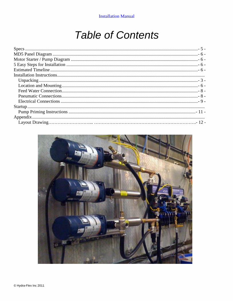
Table of Contents
Specs ....................................................................................................................................................... - 5 - MD5 Panel Diagram ............................................................................................................................... - 6 - Motor Starter / Pump Diagram ............................................................................................................... - 6 - 5 Easy Steps for Installation ................................................................................................................... - 6 - Estimated Timeline ................................................................................................................................. - 6 - Installation Instructions .................................................................................................................................
Unpacking ........................................................................................................................................... - 3 - Location and Mounting ....................................................................................................................... - 6 - Feed Water Connection....................................................................................................................... - 8 - Pneumatic Connections ....................................................................................................................... - 8 - Electrical Connections ........................................................................................................................ - 9 -
Startup ........................................................................................................................................................... Pump Priming Instructions ............................................................................................................... - 11 -
Appendix ....................................................................................................................................................... Layout Drawing………………………... ………………………………………………………….- 12 -
Installation Manual
© Hydra-Flex Inc 2011
- 1 -
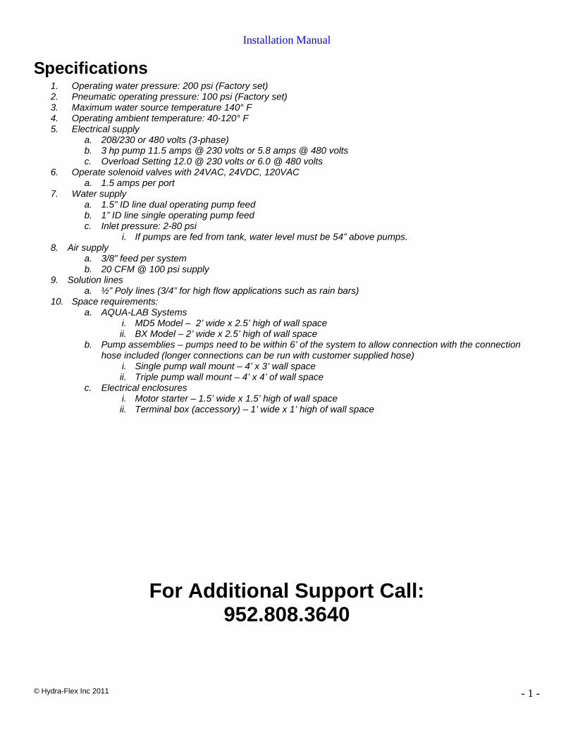
Specifications 1. Operating water pressure: 200 psi (Factory set) 2. Pneumatic operating pressure: 100 psi (Factory set) 3. Maximum water source temperature 140° F 4. Operating ambient temperature: 40-120° F 5. Electrical supply
a. 208/230 or 480 volts (3-phase) b. 3 hp pump 11.5 amps @ 230 volts or 5.8 amps @ 480 volts c. Overload Setting 12.0 @ 230 volts or 6.0 @ 480 volts
6. Operate solenoid valves with 24VAC, 24VDC, 120VAC a. 1.5 amps per port
7. Water supply a. 1.5” ID line dual operating pump feed b. 1” ID line single operating pump feed c. Inlet pressure: 2-80 psi
i. If pumps are fed from tank, water level must be 54” above pumps. 8. Air supply
a. 3/8” feed per system b. 20 CFM @ 100 psi supply
9. Solution lines a. ½” Poly lines (3/4” for high flow applications such as rain bars)
10. Space requirements: a. AQUA-LAB Systems
i. MD5 Model – 2’ wide x 2.5’ high of wall space ii. BX Model – 2’ wide x 2.5’ high of wall space
b. Pump assemblies – pumps need to be within 6’ of the system to allow connection with the connection hose included (longer connections can be run with customer supplied hose)
i. Single pump wall mount – 4’ x 3’ wall space ii. Triple pump wall mount – 4’ x 4’ of wall space
c. Electrical enclosures i. Motor starter – 1.5’ wide x 1.5’ high of wall space ii. Terminal box (accessory) – 1’ wide x 1’ high of wall space
For Additional Support Call: 952.808.3640
Installation Manual
© Hydra-Flex Inc 2011
- 2 -
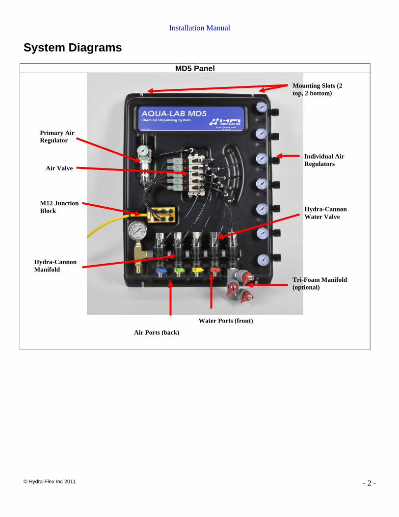
System Diagrams
MD5 Panel
Primary Air Regulator
Individual Air Regulators
Mounting Slots (2 top, 2 bottom)
Air Valve
M12 Junction Block
Hydra-Cannon Manifold
Water Ports (front)
Air Ports (back)
Tri-Foam Manifold (optional)
Hydra-Cannon Water Valve
Installation Manual
© Hydra-Flex Inc 2011
- 3 -
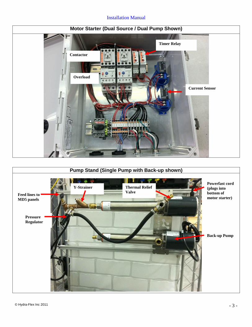
Motor Starter (Dual Source / Dual Pump Shown)
Pump Stand (Single Pump with Back-up shown)
Current Sensor
Timer Relay
Contactor
Overload
Thermal Relief Valve
Pressure Regulator
Y-Strainer
Feed lines to MD5 panels
Powerfast cord (plugs into bottom of motor starter)
Back-up Pump
Installation Manual
© Hydra-Flex Inc 2011
- 4 -
5 Easy Steps for Installation Complete Pre-Installation Checklist before these steps.
1. Unpack
2. Hang the equipment
3. Make connections
4. Start-up
5. Optimize equipment (see Operating Manual)
Installation Manual
© Hydra-Flex Inc 2011
- 5 -
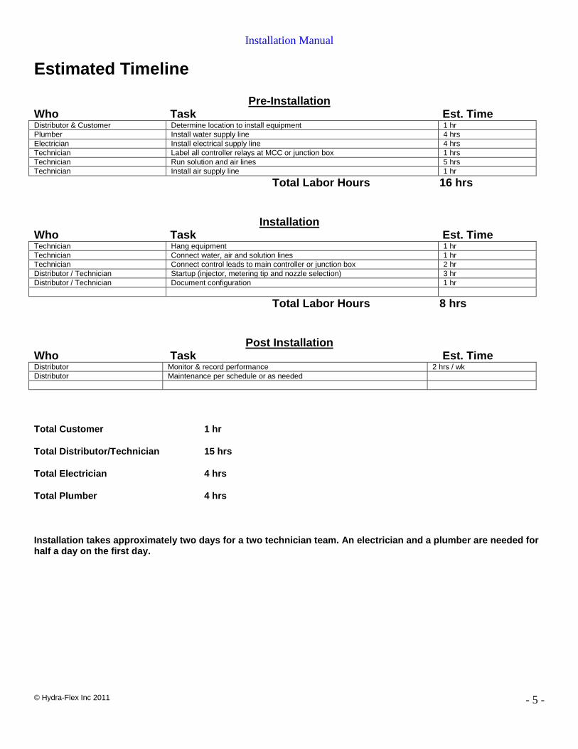
Estimated Timeline
Pre-Installation Who Task Est. Time Distributor & Customer Determine location to install equipment 1 hr Plumber Install water supply line 4 hrs Electrician Install electrical supply line 4 hrs Technician Label all controller relays at MCC or junction box 1 hrs Technician Run solution and air lines 5 hrs Technician Install air supply line 1 hr
Total Labor Hours 16 hrs
Installation Who Task Est. Time Technician Hang equipment 1 hr Technician Connect water, air and solution lines 1 hr Technician Connect control leads to main controller or junction box 2 hr Distributor / Technician Startup (injector, metering tip and nozzle selection) 3 hr Distributor / Technician Document configuration 1 hr
Total Labor Hours 8 hrs
Post Installation Who Task Est. Time Distributor Monitor & record performance 2 hrs / wk Distributor Maintenance per schedule or as needed
Total Customer 1 hr
Total Distributor/Technician 15 hrs
Total Electrician 4 hrs
Total Plumber 4 hrs
Installation takes approximately two days for a two technician team. An electrician and a plumber are needed for half a day on the first day.
Installation Manual
© Hydra-Flex Inc 2011
- 6 -
Installation Instructions General Skill Level
• Mechanical: Basic - mounting equipment • Electrical: Advanced - three phase power and controls knowledge (local codes knowledge required) • Plumbing: Moderate – principal supply line required • Pneumatic: Basic- pneumatic utility connection required • Chemical Knowledge: Moderate : Advanced - chemical titrations required
Tools and Equipment Needed • Drill with Phillips head • Concrete drill bit 3/8” • Concrete drill bit 5/32” • Hammer • Tape measure • Level
• Utility knife • Wire stripper • Socket set • Adjustable wrench • Screw driver set • Teflon tape
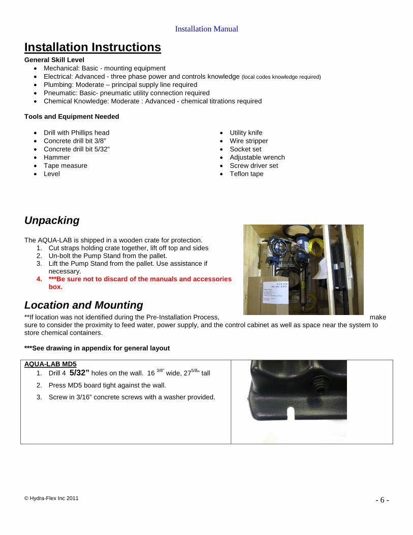
Unpacking
The AQUA-LAB is shipped in a wooden crate for protection. 1. Cut straps holding crate together, lift off top and sides 2. Un-bolt the Pump Stand from the pallet. 3. Lift the Pump Stand from the pallet. Use assistance if
necessary. 4. ***Be sure not to discard of the manuals and accessories
box.
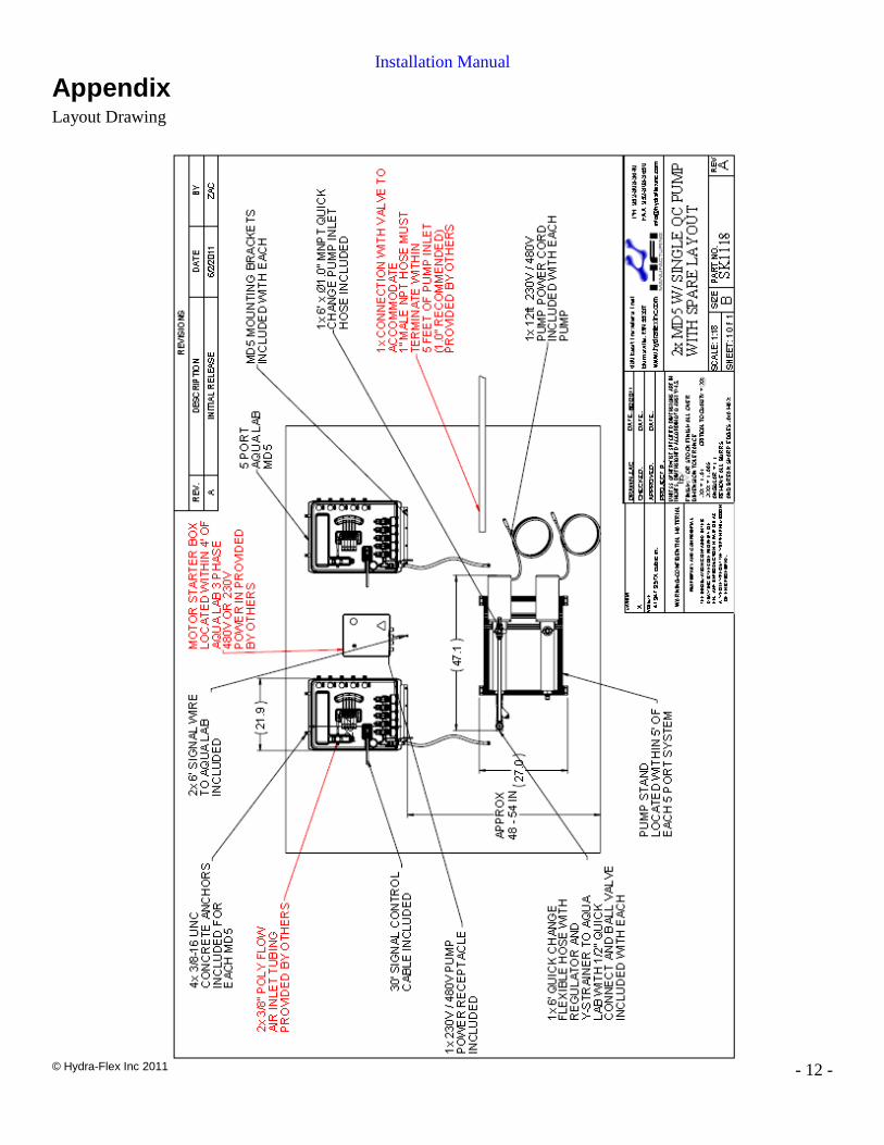
Location and Mounting **If location was not identified during the Pre-Installation Process, make sure to consider the proximity to feed water, power supply, and the control cabinet as well as space near the system to store chemical containers. ***See drawing in appendix for general layout AQUA-LAB MD5
1. Drill 4 5/32” holes on the wall. 16 3/8” wide, 275/8” tall
2. Press MD5 board tight against the wall.
3. Screw in 3/16” concrete screws with a washer provided.
Installation Manual
© Hydra-Flex Inc 2011
- 7 -
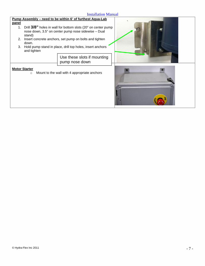
Pump Assembly – need to be within 6’ of furthest Aqua-Lab panel
1. Drill 3/8” holes in wall for bottom slots (20” on center pump nose down, 3.5” on center pump nose sidewise – Dual stand)
2. Insert concrete anchors, set pump on bolts and tighten down.
3. Hold pump stand in place, drill top holes, insert anchors and tighten
Motor Starter o Mount to the wall with 4 appropriate anchors
Use these slots if mounting pump nose down
Installation Manual
© Hydra-Flex Inc 2011
- 8 -
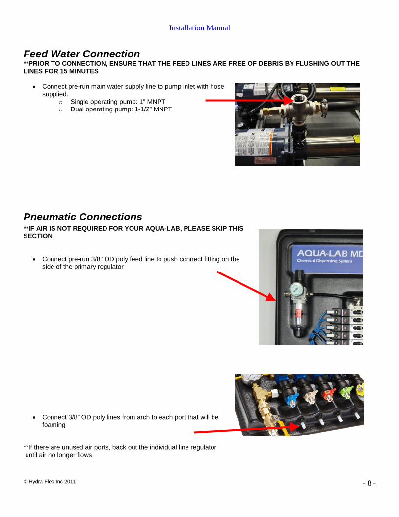
Feed Water Connection **PRIOR TO CONNECTION, ENSURE THAT THE FEED LINES ARE FREE OF DEBRIS BY FLUSHING OUT THE LINES FOR 15 MINUTES
• Connect pre-run main water supply line to pump inlet with hose supplied.
o Single operating pump: 1” MNPT o Dual operating pump: 1-1/2” MNPT
Pneumatic Connections **IF AIR IS NOT REQUIRED FOR YOUR AQUA-LAB, PLEASE SKIP THIS SECTION
• Connect pre-run 3/8" OD poly feed line to push connect fitting on the side of the primary regulator
• Connect 3/8” OD poly lines from arch to each port that will be foaming
**If there are unused air ports, back out the individual line regulator until air no longer flows
Installation Manual
© Hydra-Flex Inc 2011
- 9 -
Electrical Connections
1. Electrical Connections a. Wire yellow homerun control cables to car wash control panel
(See diagram below for wiring schematic) Manifold position below designates which port is associated to what color wire.
• Example: if you want Presoak 1 to be on manifold port 2, connect the green wire to your controller relay for Presoak 1.
********************(HFI supplied motor starter)****************
Electrical Connection
Main Trunk Cable Wire Color
GROUND Green/Yellow DO NOT USE Blue
Control Voltage Constant HOT / + Brown
Neutral / Common Red Port 1 White Port 2 Green Port 3 Yellow Port 4 Grey Port 5 Pink
(Left to right on water manifold, top to bottom on air valves refer to diagram on Page 2)
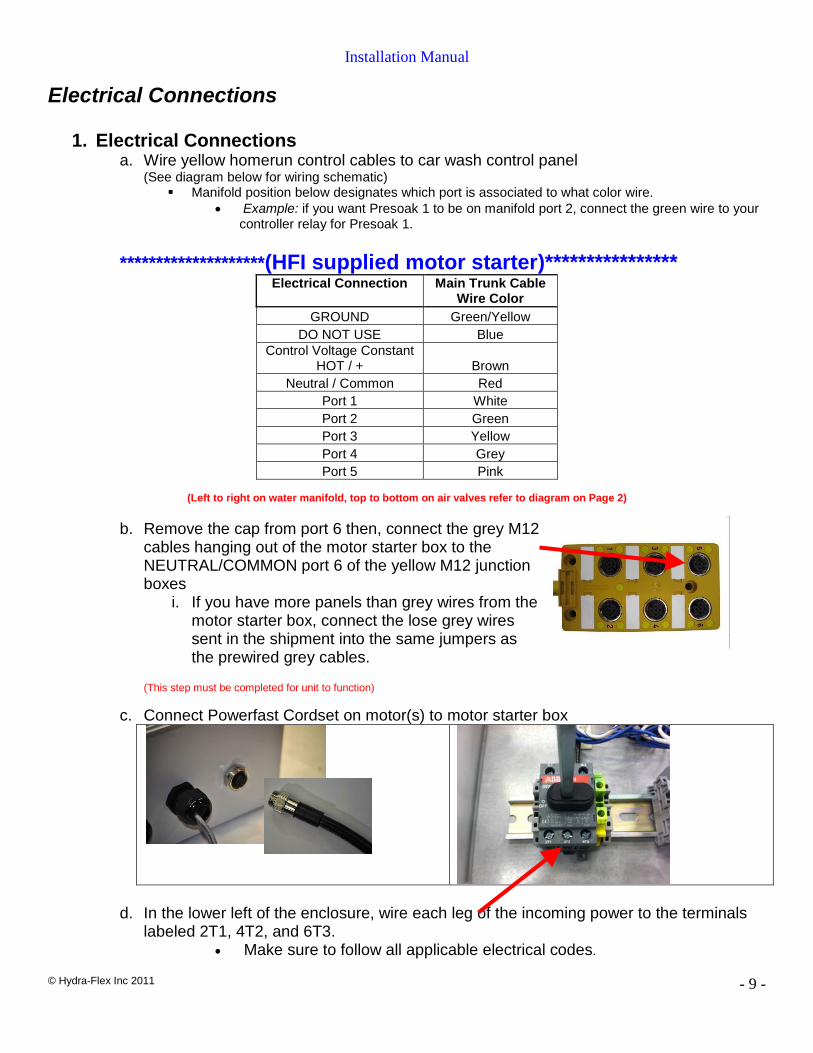
b. Remove the cap from port 6 then, connect the grey M12
cables hanging out of the motor starter box to the NEUTRAL/COMMON port 6 of the yellow M12 junction boxes
i. If you have more panels than grey wires from the motor starter box, connect the lose grey wires sent in the shipment into the same jumpers as the prewired grey cables.
(This step must be completed for unit to function)
c. Connect Powerfast Cordset on motor(s) to motor starter box
d. In the lower left of the enclosure, wire each leg of the incoming power to the terminals
labeled 2T1, 4T2, and 6T3. • Make sure to follow all applicable electrical codes.
Installation Manual
© Hydra-Flex Inc 2011
- 10 -
2. Electrical Connections a. Connect yellow homerun control cables to car wash control panel
(See diagram below for wiring schematic) Manifold Position below designates which port is associated to what color wire.
• Example: If you want Presoak 1 to be on manifold port 2, then connect the green wire to your controller relay for Presoak 1.
Schematic for Solenoid Valve Signal Connection *****************(NON - HFI supplied motor starter)*************
Manifold Port or Use Main Trunk Cable
Wire Color GROUND Green/Yellow
NEUTRAL / COMMON Blue DO NOT USE Brown
Port 1 White Port 2 Green Port 3 Yellow Port 4 Grey Port 5 Pink
DO NOT USE Red
(Left to right on water manifold, top to bottom on air valves refer to diagram on page 6)
b. Wire each leg of the power from your starter to each pump i. See diagram on pump for wiring schematic or pump manual
Installation Manual
© Hydra-Flex Inc 2011
- 11 -
Startup Pump Priming Instructions
1. Pull each pump outlet line at AQUA-LAB manifold quick-connect. Open ball valve until a steady stream of water is flowing, and then reconnect.
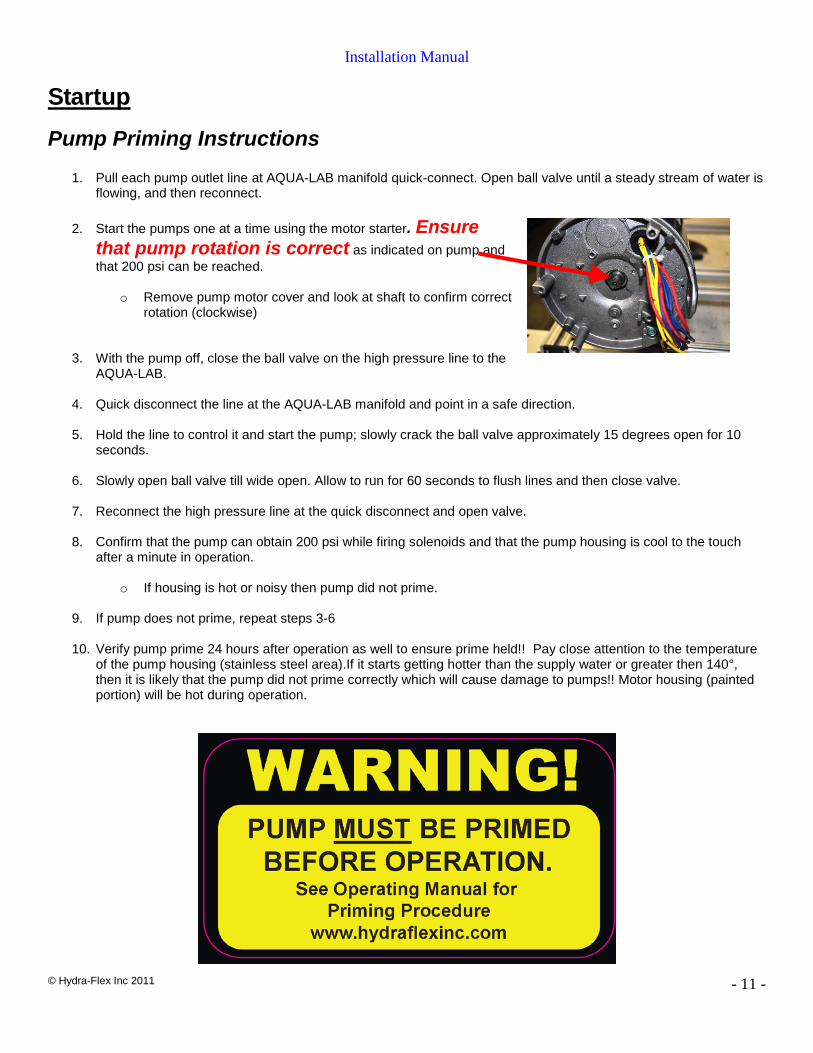
2. Start the pumps one at a time using the motor starter. Ensure
that pump rotation is correct as indicated on pump and that 200 psi can be reached.
o Remove pump motor cover and look at shaft to confirm correct
rotation (clockwise)
3. With the pump off, close the ball valve on the high pressure line to the
AQUA-LAB. 4. Quick disconnect the line at the AQUA-LAB manifold and point in a safe direction.
5. Hold the line to control it and start the pump; slowly crack the ball valve approximately 15 degrees open for 10
seconds.
6. Slowly open ball valve till wide open. Allow to run for 60 seconds to flush lines and then close valve.
7. Reconnect the high pressure line at the quick disconnect and open valve. 8. Confirm that the pump can obtain 200 psi while firing solenoids and that the pump housing is cool to the touch
after a minute in operation.
o If housing is hot or noisy then pump did not prime. 9. If pump does not prime, repeat steps 3-6 10. Verify pump prime 24 hours after operation as well to ensure prime held!! Pay close attention to the temperature
of the pump housing (stainless steel area).If it starts getting hotter than the supply water or greater then 140°, then it is likely that the pump did not prime correctly which will cause damage to pumps!! Motor housing (painted portion) will be hot during operation.
Installation Manual
© Hydra-Flex Inc 2011
- 12 -
Appendix Layout Drawing