Embed Size (px)
Citation preview

Installation Manual ECS Membrane Processor: PMC and ISD
Part: VST ECS-CS3-310 – Three Phase VST-ECS-CS3-110 – Single Phase
Executive Orders: VR-203 VR-204
Version: 1.0 (i)
Vapor Systems Technologies, Inc. 650 Pleasant Valley Drive Springboro, Ohio 45066 937-704-9333 PH 937-704-9443 FX www.vsthose.com
VST EVR Total Balance System Solution
Page 14-2 Version 1.0(i) ARB Approved IOM-14 – Processor Installation Manual – Executive Orders VR-203-D and VR-204-D
Table of Contents Table of Figures ........................................................................................................................................................... 5
UL Declaration Notice .................................................................................................................................................. 6
About VST ..................................................................................................................................................................... 7
Notice ............................................................................................................................................................................ 7
Warranty ....................................................................................................................................................................... 8
Warranty Cards ............................................................................................................................................................ 9
Components and Warranties .................................................................................................................................... 10
Activating the Processor Warranty .......................................................................................................................... 11
VST Contractor Requirements .................................................................................................................................. 12
Veeder-Root Contractor Requirements .................................................................................................................... 13
Safety Icons ................................................................................................................................................................ 14
Table of Terms & Abbreviations ............................................................................................................................... 15
1 ECS Membrane Processor Overview .............................................................................................................. 16
1.1 ECS Membrane Processor Theory of Operation ........................................................................................ 16 1.2 Overview of How the Processor Operates .................................................................................................. 17 1.3 Processor Dimensions and Weight ............................................................................................................. 17 1.4 Processor Components .............................................................................................................................. 18 1.5 Processor Auxiliary Components ................................................................................................................ 19 1.6 Explanation of VST Processor Model Numbers ......................................................................................... 19 1.7 Included with the Processor Package ......................................................................................................... 19 1.8 Contractor-Supplied Components for the Processor .................................................................................. 19
2 Pre-Installation Site Survey ............................................................................................................................. 25
3 How the Processor is Shipped ........................................................................................................................ 25
4 Preparing the Processor for Installation ........................................................................................................ 25
5 Pre-Installation Processor Leak Test .............................................................................................................. 26
5.1 Safety ......................................................................................................................................................... 26 5.2 Preparation ................................................................................................................................................. 26 5.3 Conducting the Initial Leak Check .............................................................................................................. 26
6 Site Requirements ............................................................................................................................................ 28
6.1 Regulations / Jurisdiction ............................................................................................................................ 28 6.2 Snapshot of Site Requirements .................................................................................................................. 29

VST EVR Total Balance System Solution
Page 14-3 Version 1.0(i) ARB Approved IOM-14 – Processor Installation Manual – Executive Orders VR-203-D and VR-204-D
7 Ground Installation ........................................................................................................................................... 31
7.1 Ground Installation Safety .......................................................................................................................... 31 7.2 Protecting the Processor ............................................................................................................................ 31 7.3 Ground-Mount Location .............................................................................................................................. 32 7.4 Setting the Concrete Pad ........................................................................................................................... 34
7.4.1 Processor Weight and Dimensions ......................................................................................................................... 34 7.5 Installing the Processor on the Concrete Pad ............................................................................................ 35
8 Roof-Top Installation ........................................................................................................................................ 38
8.1 Roof-Top Installation Safety ....................................................................................................................... 38 9 Canopy Top Installation ................................................................................................................................... 40
9.1 Canopy Top Installation Safety ................................................................................................................... 40 10 Vapor Piping ..................................................................................................................................................... 42
10.1 Vapor Piping Safety .................................................................................................................................... 42 10.2 Piping Connection Material ......................................................................................................................... 42 10.3 Piping Connections to the Processor .......................................................................................................... 42
10.3.1 Flexible Connections .......................................................................................................................................... 43 10.4 Trenching .................................................................................................................................................... 43 10.5 Underground Vapor Piping Instructions ...................................................................................................... 44 10.6 Vapor Inlet and Vapor Return Connections ................................................................................................ 49
10.6.1 Flexible Connections .......................................................................................................................................... 49 11 Air Outlet Connection ...................................................................................................................................... 50
11.1 Flexible Connections .................................................................................................................................. 51 11.2 Underground Piping Connection ................................................................................................................. 55 11.3 Storage Tank Vapor Manifolds ................................................................................................................... 55 11.4 P / V Valves ................................................................................................................................................ 55
12 Electrical ........................................................................................................................................................... 56
12.1 Electrical Safety .......................................................................................................................................... 56 12.2 Single-Phase Processor ............................................................................................................................. 56
12.2.1 Power Requirements for Single-Phase Electrical Service ................................................................................. 57 12.3 Three-Phase Processor .............................................................................................................................. 57
12.3.1 Power Requirements for Three-Phase Electrical Service .................................................................................. 58 12.4 Reference Information for Processor Power Requirements ....................................................................... 59 12.5 Power for the Motors .................................................................................................................................. 60
12.5.1 Single-Phase Processor .................................................................................................................................... 60 12.5.2 Three-Phase Processor ..................................................................................................................................... 60 12.5.3 Power for the HC Sensor in both the Single-Phase and the Three-Phase Processor ....................................... 60
12.6 Power for the Heat-Trace Cables in both Single-Phase and Three-Phase Processors ............................. 61 12.7 Power for the Motor Starter Relay Coil ....................................................................................................... 61 12.8 Optional Convenience Outlet at the Processor ......................................................................................... 61
VST EVR Total Balance System Solution
Page 14-4 Version 1.0(i) ARB Approved IOM-14 – Processor Installation Manual – Executive Orders VR-203-D and VR-204-D
13 Electrical Installation ........................................................................................................................................ 62
13.1 Electical Safety ........................................................................................................................................... 62 13.2 Electrical Installation Code Requirements .................................................................................................. 62
13.2.1 Single-Phase Processor Configuration .............................................................................................................. 62 13.2.2 Three-Phase Processor Configuration ............................................................................................................... 63
13.3 Single and Three-Phase Processors .......................................................................................................... 64 13.3.1 Wiring between the Processor and components: .............................................................................................. 64
13.4 Auxiliary Output Relay ................................................................................................................................ 75 13.5 HC Sensor / HC Sentry .............................................................................................................................. 77 13.6 Multiport Card for Vapor Processor Communication .................................................................................. 80 13.7 Veeder-Root TLS 350 with PMC or ISD Controls ....................................................................................... 82
14 Post-Installation Checklist ............................................................................................................................... 83
VST EVR Total Balance System Solution
Page 14-5 Version 1.0(i) ARB Approved IOM-14 – Processor Installation Manual – Executive Orders VR-203-D and VR-204-D
Table of Figures Figure 1: VST Registration Card ................................................................................................................................................... 9 Figure 2: ECS Membrane Processor Sticker ............................................................................................................................... 9 Figure 3: How the Processor fits into the GDF layout .............................................................................................................. 20 Figure 4: Processor Piping Diagram .......................................................................................................................................... 21 Figure 5: ECS Vent Configurations ............................................................................................................................................ 22 Figure 6: Processor Isometric Drawing (1 of 1) ........................................................................................................................ 23 Figure 7: Processor Isometric Drawing (2 of 2) ........................................................................................................................ 24 Figure 8: Processor Inlets & Outlets .......................................................................................................................................... 27 Figure 9: Typical Leak Check Test Fixture ................................................................................................................................ 27 Figure 10: ECS Membrane Processor Hazardous Locations .................................................................................................. 33 Figure 11: Concrete Mounting Pad Dimensions ....................................................................................................................... 36 Figure 12: Processor Ground Mounting Pad ............................................................................................................................ 37 Figure 13: Processor Connections with Multiple Vent Risers ................................................................................................. 45 Figure 14: Processor Connections with 2 Vent Risers ............................................................................................................ 46 Figure 15: Processor Connections with Single Vent Riser ...................................................................................................... 47 Figure 16: Typical GDF Vapor Piping Diagram for Processor ................................................................................................. 48 Figure 17: ECS Processor Piping Diagram ............................................................................................................................... 52 Figure 18: ECS Vent Configuration ............................................................................................................................................ 53 Figure 19: Processor Piping Connections ................................................................................................................................ 54 Figure 20: Single-Phase Wiring Schematic ............................................................................................................................... 65 Figure 21: Processor Single-Phase Wiring Diagram ................................................................................................................ 66 Figure 22: Processor Single-Phase ESO Wiring Diagram ....................................................................................................... 67 Figure 23: Vacuum Pump: Single-Phase Motor Wiring Diagram ........................................................................................... 68 Figure 24: Blower: Single-Phase Motor Wiring Diagram ........................................................................................................ 69 Figure 25: Processor Three-Phase Wiring Schematic ............................................................................................................. 70 Figure 26: Processor Three-Phase Wiring Schematic ............................................................................................................. 71 Figure 27: Processor Three-Phase ESO Wiring Diagram ........................................................................................................ 72 Figure 28: Vacuum Pump: Three-Phase Motor Wiring Diagram ............................................................................................ 73 Figure 29: Blower: Three-Phase Motor Wiring Diagram ......................................................................................................... 74 Figure 30: VR TLS Multi-Port Card Connection to HC Sentry Module .................................................................................... 76 Figure 31: HC Sentry Front & Back Views ................................................................................................................................. 77 Figure 32: HC Sentry and HC Sensor Wiring Diagram ............................................................................................................. 78 Figure 33: HC Sensor and HC Sentry Pictures ......................................................................................................................... 79 Figure 34: VR TLS Multi-Port Card Connection to the HC Sentry Module ............................................................................. 80 Figure 35: HC Sentry RS-485 Cable Wiring Diagram ................................................................................................................ 81 Figure 36: VR TLS-350 ................................................................................................................................................................. 82
VST EVR Total Balance System Solution
Page 14-6 Version 1.0(i) ARB Approved IOM-14 – Processor Installation Manual – Executive Orders VR-203-D and VR-204-D
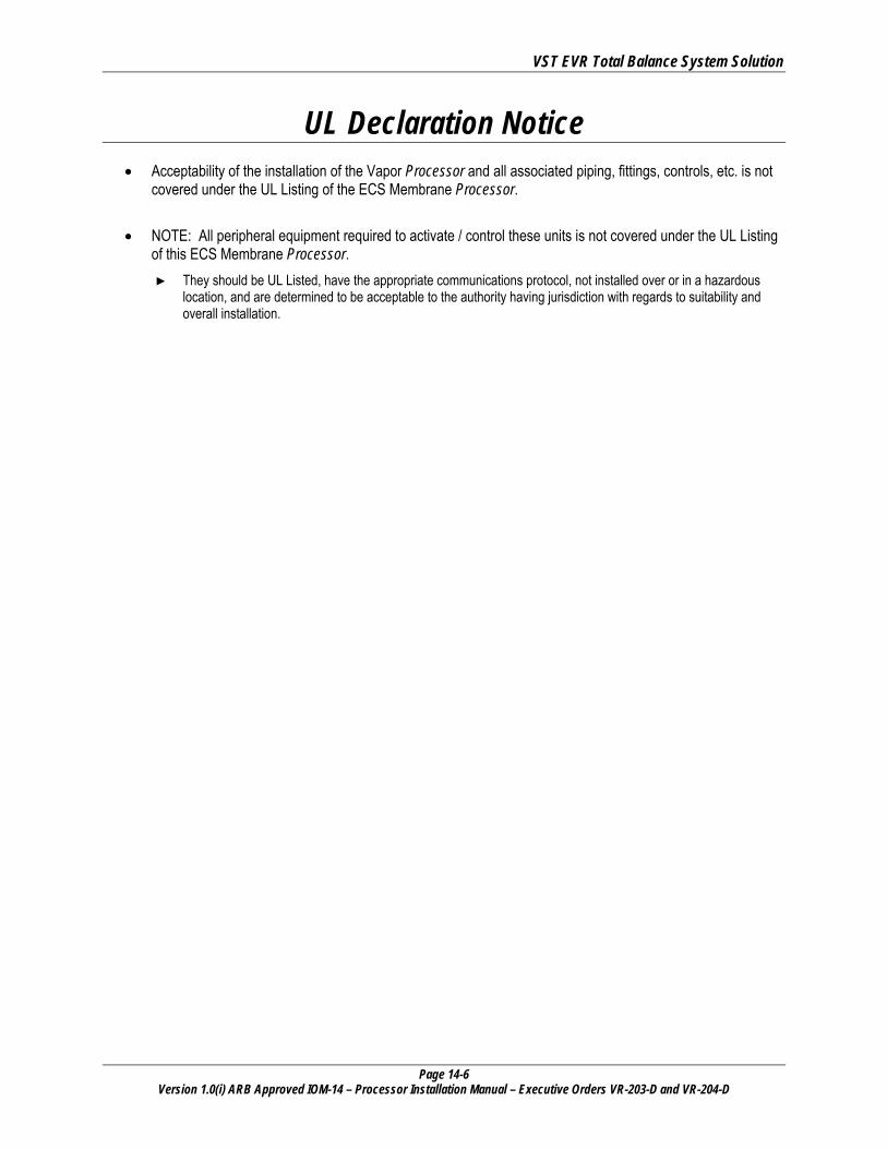
UL Declaration Notice • Acceptability of the installation of the Vapor Processor and all associated piping, fittings, controls, etc. is not
covered under the UL Listing of the ECS Membrane Processor.
• NOTE: All peripheral equipment required to activate / control these units is not covered under the UL Listing of this ECS Membrane Processor. ► They should be UL Listed, have the appropriate communications protocol, not installed over or in a hazardous
location, and are determined to be acceptable to the authority having jurisdiction with regards to suitability and overall installation.
VST EVR Total Balance System Solution
Page 14-7 Version 1.0(i) ARB Approved IOM-14 – Processor Installation Manual – Executive Orders VR-203-D and VR-204-D
About VST Vapor Systems Technologies, Inc. began in 1989 with the vision of One Company – One Integrated Solution. Today, that philosophy is still in place and getting stronger. Recognizing that a healthier environment is a need and not an option, VST has dedicated its
undivided attention to the ever-changing, stringent regulations that govern fugitive vapors at gasoline dispensing facilities (GDF). To this challenge, VST is committed to a continual R&D campaign of developing the most current, technologically advanced solutions to service not only the United States, but also the world. VST specializes in the development, engineering, and manufacturing of products that are sold into the GDF segment of the petroleum industry. The VST focus provides our customers and users with exceptional products, services, and innovative solutions for improving the fueling-station experience as well as the world’s air quality. VST’s product offering includes curb pump and vapor recovery hoses, safety breakaways, nozzles, and emission-control system Processors. The ENVIRO-LOC™ vapor-recovery product offering represents the most innovative concept in the industry for trapping fugitive vapors from the front end (vehicle refueling) to the back end (vent risers) of the GDF site.
Notice Vapor Systems Technologies, Inc. shall not be liable for errors contained herein or for incidental or consequential damages in connection with the furnishing, performance, or use of this publication. No part of this publication may be translated to another language without the prior written consent of Vapor Systems Technologies, Inc.
VST EVR Total Balance System Solution
Page 14-8 Version 1.0(i) ARB Approved IOM-14 – Processor Installation Manual – Executive Orders VR-203-D and VR-204-D
Warranty • The warranty is conditional on whether the Processor was installed by a VST ASC Level B or a
VST Level C.
• 12-month warranty becomes effective at the time of installation. If this card is not returned, the warranty becomes effective from the date of shipment at VST.
• VST cannot be held responsible for damage to the Processor or the Processor equipment (inclusive) due to acts of nature, vandalism, or neglect.
• Membranes exposed to gasoline (liquid) due to an overfill or any other reason voids the membrane warranty.
• VST products are warranted to be free of defects in material and workmanship.
• Liability under any expressed or implied warranty is limited to replacement of the product.
• Use of VST products on non-UL Listed systems, or use which falls outside intended field of use, voids any stated or implied warranty.
• VST is not responsible for misuse of, nor improperly installed, products.
• In the event of a warranty claim, the purchaser must obtain a copy of the Return Goods Authorization (RGA) prior to returning product to insure proper processing. Return shipping charges are the responsibility of the customer.
• Warranty status will be determined within 30 days of the return of suspected items.
• VST provides for a warranty program in conjunction with VST’s exclusive serial number tracking system.
• Each VST product carries a unique serial number and warranty tracking card.
• Requests for warranty shall be through VST’s Return Goods Authorization (RGA) procedure. Call VST at 937-704-9333.
• This warranty does not cover any components exposed to contact with fuels more than 5% menthanol, 10% ethanol, 15% MTBE by volume or any exposure to M85 / E85 fuel.
VST EVR Total Balance System Solution
Page 14-9 Version 1.0(i) ARB Approved IOM-14 – Processor Installation Manual – Executive Orders VR-203-D and VR-204-D
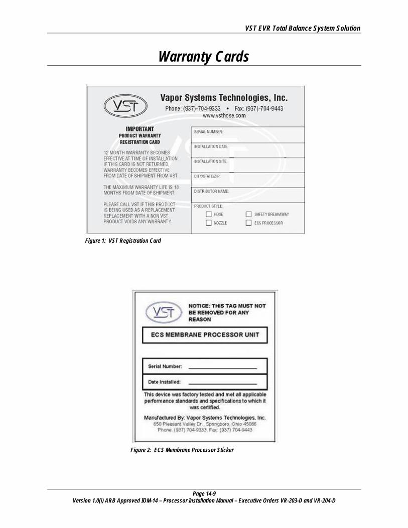
Warranty Cards
Figure 1: VST Registration Card
Figure 2: ECS Membrane Processor Sticker
VST EVR Total Balance System Solution
Page 14-10 Version 1.0(i) ARB Approved IOM-14 – Processor Installation Manual – Executive Orders VR-203-D and VR-204-D
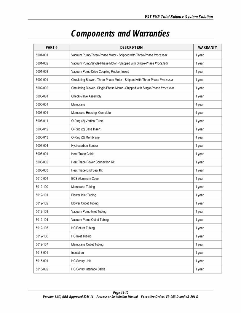
Components and Warranties PART # DESCRIPTION WARRANTY
5001-001 Vacuum Pump/Three-Phase Motor - Shipped with Three-Phase Processor 1 year
5001-002 Vacuum Pump/Single-Phase Motor - Shipped with Single-Phase Processor 1 year
5001-003 Vacuum Pump Drive Coupling Rubber Insert 1 year
5002-001 Circulating Blower / Three-Phase Motor - Shipped with Three-Phase Processor 1 year
5002-002 Circulating Blower / Single-Phase Motor - Shipped with Single-Phase Processor 1 year
5003-001 Check-Valve Assembly 1 year
5005-001 Membrane 1 year
5006-001 Membrane Housing, Complete 1 year
5006-011 O-Ring (2) Vertical Tube 1 year
5006-012 O-Ring (2) Base Insert 1 year
5006-013 O-Ring (2) Membrane 1 year
5007-004 Hydrocarbon Sensor 1 year
5008-001 Heat-Trace Cable 1 year
5008-002 Heat Trace Power Connection Kit 1 year
5008-003 Heat Trace End Seal Kit 1 year
5010-001 ECS Aluminum Cover 1 year
5012-100 Membrane Tubing 1 year
5012-101 Blower Inlet Tubing 1 year
5012-102 Blower Outlet Tubing 1 year
5012-103 Vacuum Pump Inlet Tubing 1 year
5012-104 Vacuum Pump Outlet Tubing 1 year
5012-105 HC Return Tubing 1 year
5012-106 HC Inlet Tubing 1 year
5012-107 Membrane Outlet Tubing 1 year
5013-001 Insulation 1 year
5015-001 HC Sentry Unit 1 year
5015-002 HC Sentry Interface Cable 1 year
VST EVR Total Balance System Solution
Page 14-11 Version 1.0(i) ARB Approved IOM-14 – Processor Installation Manual – Executive Orders VR-203-D and VR-204-D
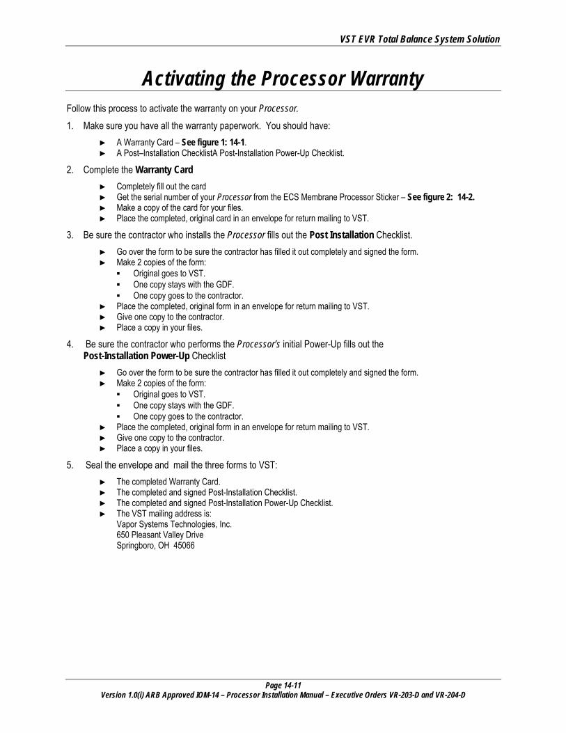
Activating the Processor Warranty Follow this process to activate the warranty on your Processor.
1. Make sure you have all the warranty paperwork. You should have: ► A Warranty Card – See figure 1: 14-1. ► A Post–Installation ChecklistA Post-Installation Power-Up Checklist.
2. Complete the Warranty Card ► Completely fill out the card ► Get the serial number of your Processor from the ECS Membrane Processor Sticker – See figure 2: 14-2. ► Make a copy of the card for your files. ► Place the completed, original card in an envelope for return mailing to VST.
3. Be sure the contractor who installs the Processor fills out the Post Installation Checklist. ► Go over the form to be sure the contractor has filled it out completely and signed the form. ► Make 2 copies of the form:
▪ Original goes to VST. ▪ One copy stays with the GDF. ▪ One copy goes to the contractor.
► Place the completed, original form in an envelope for return mailing to VST. ► Give one copy to the contractor. ► Place a copy in your files.
4. Be sure the contractor who performs the Processor’s initial Power-Up fills out the Post-Installation Power-Up Checklist
► Go over the form to be sure the contractor has filled it out completely and signed the form. ► Make 2 copies of the form:
▪ Original goes to VST. ▪ One copy stays with the GDF. ▪ One copy goes to the contractor.
► Place the completed, original form in an envelope for return mailing to VST. ► Give one copy to the contractor. ► Place a copy in your files.
5. Seal the envelope and mail the three forms to VST: ► The completed Warranty Card. ► The completed and signed Post-Installation Checklist. ► The completed and signed Post-Installation Power-Up Checklist. ► The VST mailing address is:
Vapor Systems Technologies, Inc. 650 Pleasant Valley Drive Springboro, OH 45066
VST EVR Total Balance System Solution
Page 14-12 Version 1.0(i) ARB Approved IOM-14 – Processor Installation Manual – Executive Orders VR-203-D and VR-204-D
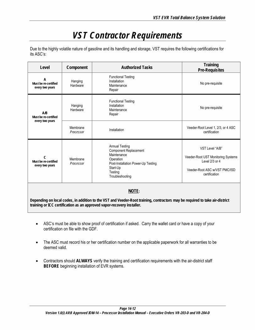
VST Contractor Requirements Due to the highly volatile nature of gasoline and its handling and storage, VST requires the following certifications for its ASC’s:
Level Component Authorized Tasks Training Pre-Requisites
A Must be re-certified
every two years Hanging
Hardware
Functional Testing Installation Maintenance Repair
No pre-requisite
A/B Must be re-certified
every two years
Hanging Hardware
Functional Testing Installation Maintenance Repair
No pre-requisite
Membrane Processor Installation Veeder-Root Level 1, 2/3, or 4 ASC
certification
C Must be re-certified
every two years Membrane Processor
Annual Testing Component Replacement Maintenance Operation Post-Installation Power-Up Testing Start-Up Testing Troubleshooting
VST Level “A/B”
Veeder-Root UST Monitoring Systems Level 2/3 or 4
Veeder-Root ASC w/VST PMC/ISD
certification
NOTE:
Depending on local codes, in addition to the VST and Veeder-Root training, contractors may be required to take air-district training or ICC certification as an approved vapor-recovery installer.
• ASC’s must be able to show proof of certification if asked. Carry the wallet card or have a copy of your certification on file with the GDF.
• The ASC must record his or her certification number on the applicable paperwork for all warranties to be deemed valid.
• Contractors should ALWAYS verify the training and certification requirements with the air-district staff BEFORE beginning installation of EVR systems.

VST EVR Total Balance System Solution
Page 14-13 Version 1.0(i) ARB Approved IOM-14 – Processor Installation Manual – Executive Orders VR-203-D and VR-204-D
Veeder-Root Contractor Requirements
Veeder-Root Level 1
Contractors holding valid Level 1 Certification are approved to perform wiring and conduit routing, equipment mounting, probe and sensor installation, tank and line preparation, and line leak detector installation.
Veeder-Root Level 2/3 or 4
Contractors holding valid Level 2, 3, or 4 certifications are approved to perform installation checkout, startup, programming and operations training, troubleshooting and servicing for all Veeder-Root Tank Monitoring Systems, including Line Leak Detection and associated accessories.
PMC / ISD
This course of training includes In-Stations Diagnostics/Pressure Management Control (ISD/PMC) installation checkout, startup, programming, and operations training. It also includes troubleshooting and service techniques for the Veeder-Root In-Station Diagnostics system. A current level 2/3 or 4 certification is a prerequisite for the ISD/PMC course. After successful completion of this course the contractor will receive a certificate as well as a Veeder-Root ISD/PMC contractor certification card.
Warranty Registrations may only be submitted by selected distributors.
VST EVR Total Balance System Solution
Page 14-14 Version 1.0(i) ARB Approved IOM-14 – Processor Installation Manual – Executive Orders VR-203-D and VR-204-D
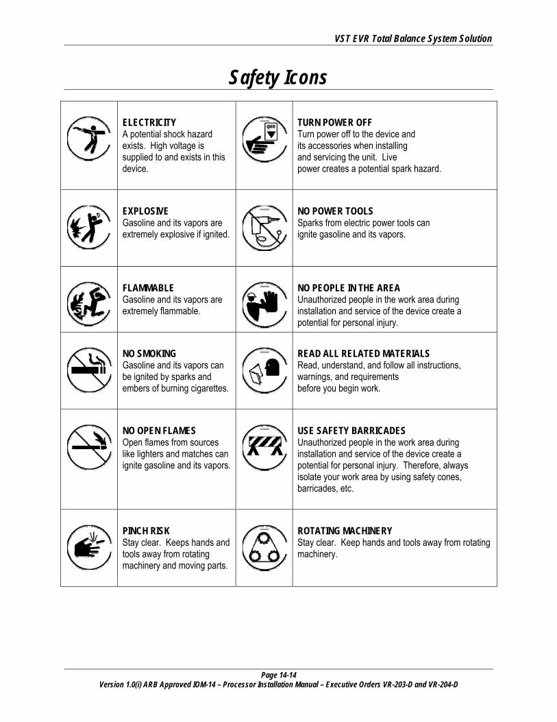
Safety Icons
ELECTRICITY A potential shock hazard exists. High voltage is supplied to and exists in this device.
TURN POWER OFF Turn power off to the device and its accessories when installing and servicing the unit. Live power creates a potential spark hazard.
EXPLOSIVE Gasoline and its vapors are extremely explosive if ignited.
NO POWER TOOLS Sparks from electric power tools can ignite gasoline and its vapors.
FLAMMABLE Gasoline and its vapors are extremely flammable.
NO PEOPLE IN THE AREA Unauthorized people in the work area during installation and service of the device create a potential for personal injury.
NO SMOKING Gasoline and its vapors can be ignited by sparks and embers of burning cigarettes.
READ ALL RELATED MATERIALS Read, understand, and follow all instructions, warnings, and requirements before you begin work.
NO OPEN FLAMES Open flames from sources like lighters and matches can ignite gasoline and its vapors.
USE SAFETY BARRICADES Unauthorized people in the work area during installation and service of the device create a potential for personal injury. Therefore, always isolate your work area by using safety cones, barricades, etc.
PINCH RISK Stay clear. Keeps hands and tools away from rotating machinery and moving parts.
ROTATING MACHINERY Stay clear. Keep hands and tools away from rotating machinery.
VST EVR Total Balance System Solution
Page 14-15 Version 1.0(i) ARB Approved IOM-14 – Processor Installation Manual – Executive Orders VR-203-D and VR-204-D
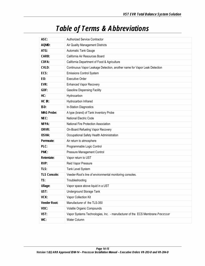
Table of Terms & Abbreviations ASC: Authorized Service Contractor AQMD: Air Quality Management Districts ATG: Automatic Tank Gauge CARB: California Air Resources Board CDFA: California Department of Food & Agriculture CVLD: Continuous Vapor Leakage Detection, another name for Vapor Leak Detection ECS: Emissions Control System EO: Executive Order EVR: Enhanced Vapor Recovery GDF: Gasoline Dispensing Facility HC: Hydrocarbon HC IR: Hydrocarbon Infrared ISD: In-Station Diagnostics MAG Probe: A type (brand) of Tank Inventory Probe NEC: National Electric Code NFPA: National Fire Protection Association ORVR: On-Board Refueling Vapor Recovery OSHA: Occupational Safety Health Administration Permeate: Air return to atmosphere PLC: Programmable Logic Control PMC: Pressure Management Control Retentate: Vapor return to UST RVP: Reid Vapor Pressure TLS: Tank Level System TLS Console: Veeder-Root’s line of environmental monitoring consoles. TS: Troubleshooting Ullage: Vapor space above liquid in a UST UST: Underground Storage Tank VCK: Vapor Collection Kit Veeder Root: Manufacturer of the TLS-350 VOC: Volatile Organic Compounds VST: Vapor Systems Technologies, Inc. - manufacturer of the ECS Membrane Processor WC: Water Column
VST EVR Total Balance System Solution
Page 14-16 Version 1.0(i) ARB Approved IOM-14 – Processor Installation Manual – Executive Orders VR-203-D and VR-204-D
1 ECS Membrane Processor Overview
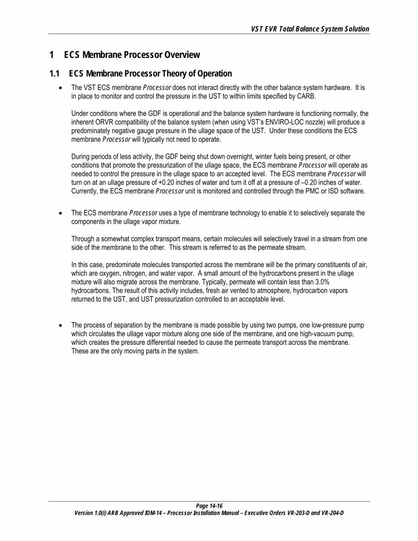
1.1 ECS Membrane Processor Theory of Operation • The VST ECS membrane Processor does not interact directly with the other balance system hardware. It is
in place to monitor and control the pressure in the UST to within limits specified by CARB. Under conditions where the GDF is operational and the balance system hardware is functioning normally, the inherent ORVR compatibility of the balance system (when using VST’s ENVIRO-LOC nozzle) will produce a predominately negative gauge pressure in the ullage space of the UST. Under these conditions the ECS membrane Processor will typically not need to operate. During periods of less activity, the GDF being shut down overnight, winter fuels being present, or other conditions that promote the pressurization of the ullage space, the ECS membrane Processor will operate as needed to control the pressure in the ullage space to an accepted level. The ECS membrane Processor will turn on at an ullage pressure of +0.20 inches of water and turn it off at a pressure of –0.20 inches of water. Currently, the ECS membrane Processor unit is monitored and controlled through the PMC or ISD software.
• The ECS membrane Processor uses a type of membrane technology to enable it to selectively separate the components in the ullage vapor mixture. Through a somewhat complex transport means, certain molecules will selectively travel in a stream from one side of the membrane to the other. This stream is referred to as the permeate stream. In this case, predominate molecules transported across the membrane will be the primary constituents of air, which are oxygen, nitrogen, and water vapor. A small amount of the hydrocarbons present in the ullage mixture will also migrate across the membrane. Typically, permeate will contain less than 3.0% hydrocarbons. The result of this activity includes, fresh air vented to atmosphere, hydrocarbon vapors returned to the UST, and UST pressurization controlled to an acceptable level.
• The process of separation by the membrane is made possible by using two pumps, one low-pressure pump which circulates the ullage vapor mixture along one side of the membrane, and one high-vacuum pump, which creates the pressure differential needed to cause the permeate transport across the membrane. These are the only moving parts in the system.
VST EVR Total Balance System Solution
Page 14-17 Version 1.0(i) ARB Approved IOM-14 – Processor Installation Manual – Executive Orders VR-203-D and VR-204-D
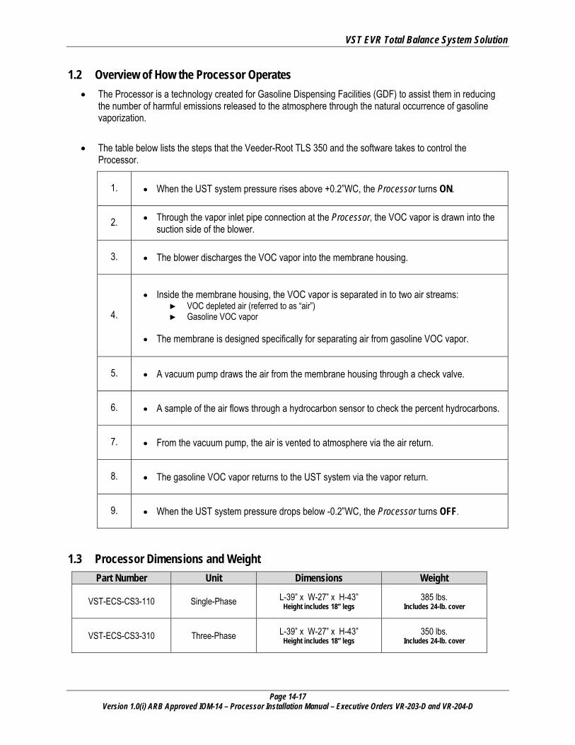
1.2 Overview of How the Processor Operates • The Processor is a technology created for Gasoline Dispensing Facilities (GDF) to assist them in reducing
the number of harmful emissions released to the atmosphere through the natural occurrence of gasoline vaporization.
• The table below lists the steps that the Veeder-Root TLS 350 and the software takes to control the Processor.
1. • When the UST system pressure rises above +0.2”WC, the Processor turns ON.
2. • Through the vapor inlet pipe connection at the Processor, the VOC vapor is drawn into the suction side of the blower.
3. • The blower discharges the VOC vapor into the membrane housing.
4.
• Inside the membrane housing, the VOC vapor is separated in to two air streams:
► VOC depleted air (referred to as “air”) ► Gasoline VOC vapor
• The membrane is designed specifically for separating air from gasoline VOC vapor.
5. • A vacuum pump draws the air from the membrane housing through a check valve.
6. • A sample of the air flows through a hydrocarbon sensor to check the percent hydrocarbons.
7. • From the vacuum pump, the air is vented to atmosphere via the air return.
8. • The gasoline VOC vapor returns to the UST system via the vapor return.
9. • When the UST system pressure drops below -0.2”WC, the Processor turns OFF.
1.3 Processor Dimensions and Weight Part Number Unit Dimensions Weight
VST-ECS-CS3-110 Single-Phase L-39” x W-27” x H-43” Height includes 18” legs
385 lbs. Includes 24-lb. cover
VST-ECS-CS3-310 Three-Phase L-39” x W-27” x H-43” Height includes 18” legs
350 lbs. Includes 24-lb. cover
VST EVR Total Balance System Solution
Page 14-18 Version 1.0(i) ARB Approved IOM-14 – Processor Installation Manual – Executive Orders VR-203-D and VR-204-D
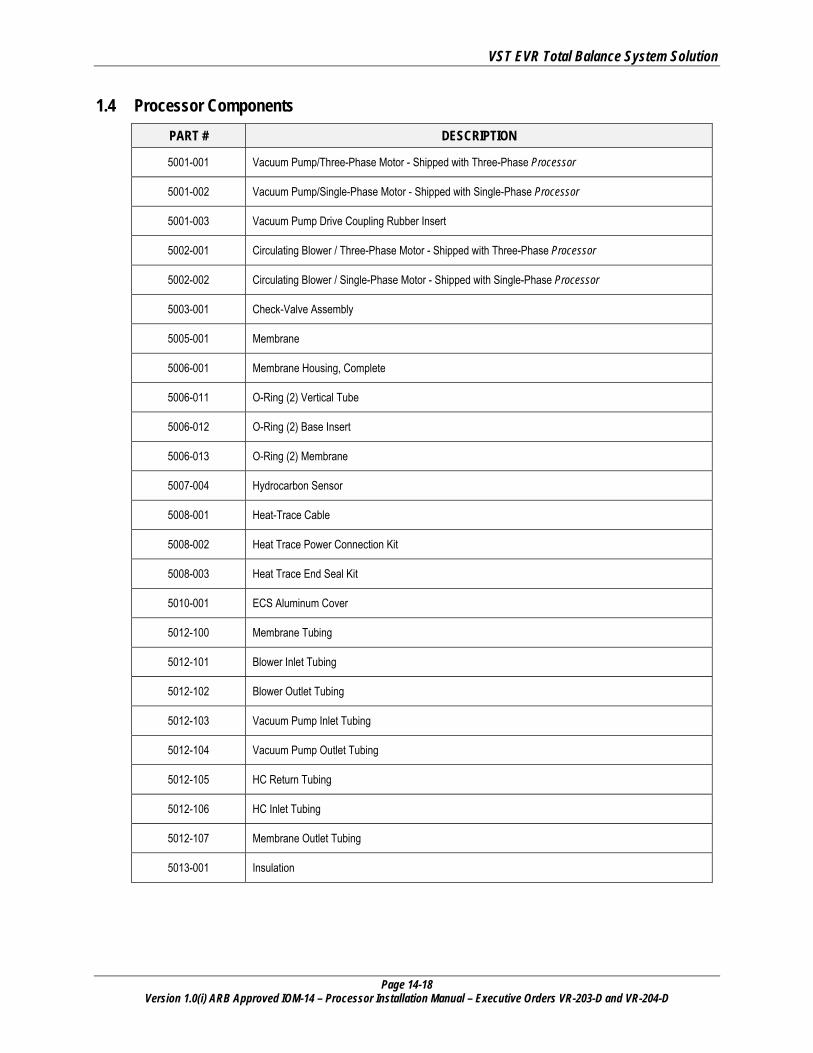
1.4 Processor Components PART # DESCRIPTION
5001-001 Vacuum Pump/Three-Phase Motor - Shipped with Three-Phase Processor
5001-002 Vacuum Pump/Single-Phase Motor - Shipped with Single-Phase Processor
5001-003 Vacuum Pump Drive Coupling Rubber Insert
5002-001 Circulating Blower / Three-Phase Motor - Shipped with Three-Phase Processor
5002-002 Circulating Blower / Single-Phase Motor - Shipped with Single-Phase Processor
5003-001 Check-Valve Assembly
5005-001 Membrane
5006-001 Membrane Housing, Complete
5006-011 O-Ring (2) Vertical Tube
5006-012 O-Ring (2) Base Insert
5006-013 O-Ring (2) Membrane
5007-004 Hydrocarbon Sensor
5008-001 Heat-Trace Cable
5008-002 Heat Trace Power Connection Kit
5008-003 Heat Trace End Seal Kit
5010-001 ECS Aluminum Cover
5012-100 Membrane Tubing
5012-101 Blower Inlet Tubing
5012-102 Blower Outlet Tubing
5012-103 Vacuum Pump Inlet Tubing
5012-104 Vacuum Pump Outlet Tubing
5012-105 HC Return Tubing
5012-106 HC Inlet Tubing
5012-107 Membrane Outlet Tubing
5013-001 Insulation

VST EVR Total Balance System Solution
Page 14-19 Version 1.0(i) ARB Approved IOM-14 – Processor Installation Manual – Executive Orders VR-203-D and VR-204-D
1.5 Processor Auxiliary Components PART # DESCRIPTION
5015-001 HC Sentry Interface Module w/24VDC power supply
5015-002 HC Sentry Interface Cable
1.6 Explanation of VST Processor Model Numbers • The GDF owner can choose the model number of the Processor based on the electrical availability at the
GDF. ► All the electrical requirements are the same, except for the motors, where the choice is between single-phase and
three-phase power.
• There are two choices of Processors: ► VST-ECS-CS3-110: Single-Phase: The single-phase refers to the motor requirements. ► VST-ECS-CS3-310: Three-Phase: The three-phase refers to the motor requirements.
1.7 Included with the Processor Package • ECS Membrane Processor
• Bolted to a skid
• (4) 18” attached legs
• Attached aluminum cover
• Packaged with the processor in a separate, smaller box: ► HC Sentry Module ► 24-volt Power Supply ► HC Sentry Interface Cable
• Owner package with warranty paperwork to be filled out and returned to VST in order to activate the warranty
1.8 Contractor-Supplied Components for the Processor NOTE: This is not an exhaustive list. There may be more components the contractor will have to supply.
• Motor Starters • Ball Valves • Tees • Piping • Pipe Fittings • Electrical • Electrical Fittings • Conduit
• Lockable Disconnect • Wires • Electrical Seal-Offs • Concrete • Veeder-Root TLS-350 • Veeder-Root PMC or ISD Software • Veeder-Root Pressure Sensor • Veeder-Root Flow Meters (ISD only)

VST EVR Total Balance System Solution
Page 14-20 Version 1.0(i) ARB Approved IOM-14 – Processor Installation Manual – Executive Orders VR-203-D and VR-204-D
Figure 3: How the Processor fits into the GDF layout

VST EVR Total Balance System Solution
Page 14-21 Version 1.0(i) ARB Approved IOM-14 – Processor Installation Manual – Executive Orders VR-203-D and VR-204-D
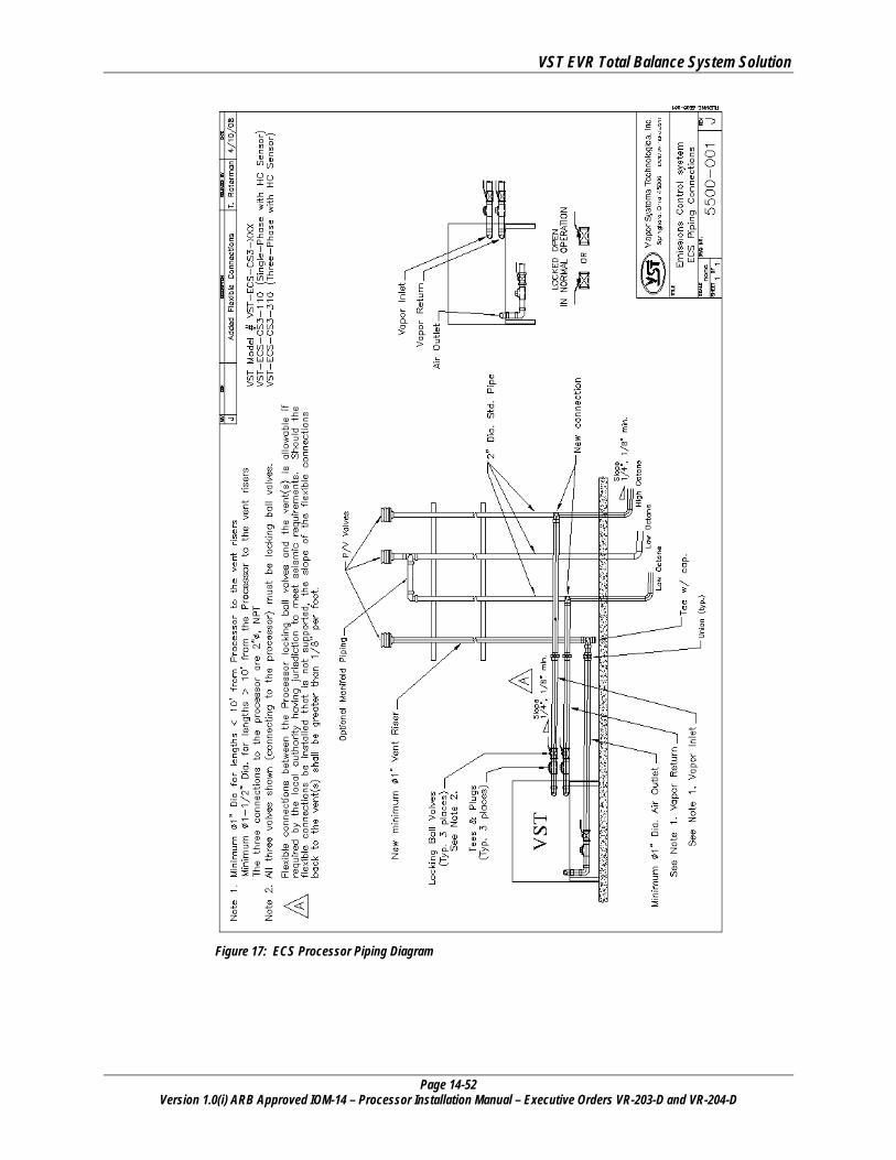
Figure 4: Processor Piping Diagram
VST EVR Total Balance System Solution
Page 14-22 Version 1.0(i) ARB Approved IOM-14 – Processor Installation Manual – Executive Orders VR-203-D and VR-204-D
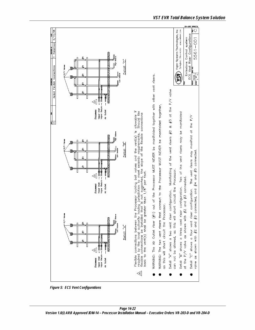
Figure 5: ECS Vent Configurations
VST EVR Total Balance System Solution
Page 14-23 Version 1.0(i) ARB Approved IOM-14 – Processor Installation Manual – Executive Orders VR-203-D and VR-204-D
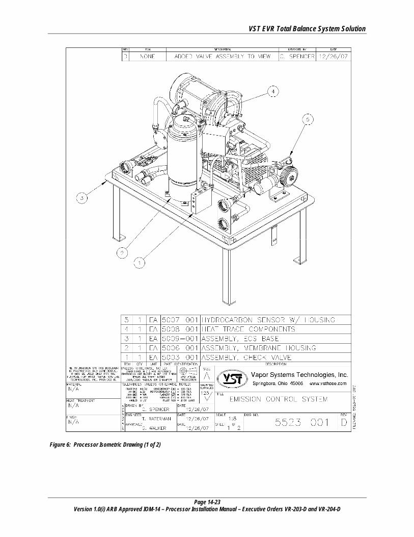
Figure 6: Processor Isometric Drawing (1 of 2)
VST EVR Total Balance System Solution
Page 14-24 Version 1.0(i) ARB Approved IOM-14 – Processor Installation Manual – Executive Orders VR-203-D and VR-204-D
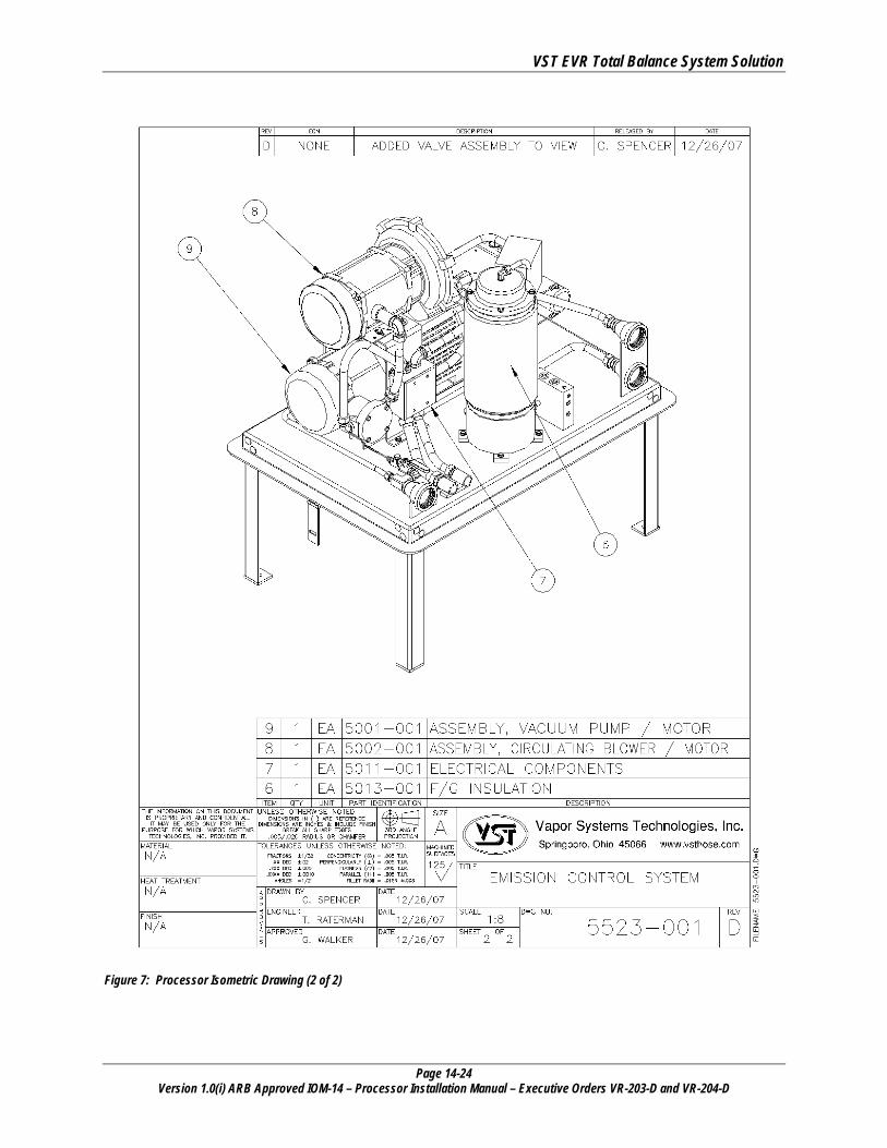
Figure 7: Processor Isometric Drawing (2 of 2)
VST EVR Total Balance System Solution
Page 14-25 Version 1.0(i) ARB Approved IOM-14 – Processor Installation Manual – Executive Orders VR-203-D and VR-204-D
2 Pre-Installation Site Survey Vapor Systems Technologies, Inc. created a “Pre-Installation Site Survey,” as a guide to help certified installers and troubleshooters in the planning of an ECS Membrane Processor installation. The “Pre-Installation Site Survey” is to be completely filled out in advance of an installation so that installation problems and delays are reduced or avoided. You will find the “Pre-Installation Site Survey” on our website at www.vsthose.com.
3 How the Processor is Shipped • The Processor is shipped with the following:
► ECS Membrane Processor ► Bolted to a skid ► (4) 18” attached legs ► Attached aluminum cover ► HC Sentry Module ► 24-volt power supply ► HC Sentry Interface Cable ► Owner package with warranty paperwork to be filled out and returned to VST in order to activate the warranty
4 Preparing the Processor for Installation • Follow these steps to prepare the Processor for installation:
1. Verify that all the items are in the shipping crate.
2. Visually inspect all the items for any obvious damage.
3. Before mounting the Processor, conduct the Pre-Installation Processor Leak Test.
Be sure to conduct a Pre-Installation Processor Leak Test before mounting the Processor to verify that the Processor is leak tight.
VST EVR Total Balance System Solution
Page 14-26 Version 1.0(i) ARB Approved IOM-14 – Processor Installation Manual – Executive Orders VR-203-D and VR-204-D
5 Pre-Installation Processor Leak Test
5.1 Safety • The purpose of the pre-installation leak check is to insure that all of the tubing fittings and tubes located
inside the Processor are leak-free prior to installation.
5.2 Preparation Follow these steps to prepare the Processor for the pre-installation leak check after the Processor is delivered to the GDF where it will be installed. Prior to installation:
1. Remove the packaging from the skid.
2. Optional: Remove the Processor from the skid.
3. Remove the cover from the Processor.
4. Place 2” NPT plugs in two of the pipe connection openings: See figure 8: 14-27. • VST recommends placing the plugs in the Vapor Inlet and Vapor Return locations. • The third 2” NPT pipe opening (Air Outlet) will be used for testing.
5.3 Conducting the Initial Leak Check 1. Install a 2” NPT pipe plug in the empty 2” pipe connection on the Processor:
• This plug must have a ¼” NPT tapped hole for attaching the nitrogen air line.
2. The leak check is conducted with 1.0 to 2.0 PSI nitrogen.
3. A pressure regulator must be used either on the compressed nitrogen bottle or at the ¼” NPT fitting where the nitrogen is connected. See figure 9: 14-27.
4. Slowly pressurize the Processor to a maximum of 2.0 PSI compressed nitrogen.
CAUTION: PRESSURIZING THE PROCESSOR OVER A MAXIMUM OF 5.0 PSI MAY CAUSE DAMAGE TO THE PROCESSOR O-RINGS AND/OR PUMP SEALS, WHICH WILL VOID ALL WARRANTIES OF THE PROCESSOR 5. With the Processor pressurized between 1.0 to 2.0 PSI compressed nitrogen, spray a soapy solution
on each fitting to check for bubbles: • If bubbles do not appear, the connection is tight. • If bubbles do appear, tighten the leaking fitting 1/8” turn and re-check for leaks. • If the fitting cannot be tightened so that the connection is leak free, replace the 45° flare
tube assembly that is leaking with a new tube assembly.
6. Continue this process until all the internal tube fittings have been checked and found leak free.
7. Remove the compressed nitrogen connection to the Processor.
8. Once this test is complete, remove the three 2” NPT plugs previously installed.
9. The Processor is now ready to install.

VST EVR Total Balance System Solution
Page 14-27 Version 1.0(i) ARB Approved IOM-14 – Processor Installation Manual – Executive Orders VR-203-D and VR-204-D
Air Outlet
Vapor Inlet
Vapor Return
Figure 8: Processor Inlets & Outlets
Figure 9: Typical Leak Check Test Fixture
VST EVR Total Balance System Solution
Page 14-28 Version 1.0(i) ARB Approved IOM-14 – Processor Installation Manual – Executive Orders VR-203-D and VR-204-D
C A U T I O N
Always obtain approval from the local authority having jurisdiction. Installation of the Processor must comply with (if applicable): • CARB CP-201 • VST EVR E.O. • Fire Marshall • Water Board • Local Air Pollution
District • ICC • NEC • NFPA 30 and 30A • UL • Any other applicable
federal, state, and local codes
6 Site Requirements
Be sure to read and understand all site requirements before beginning an installation.
6.1 Regulations / Jurisdiction • Under vapor recovery rules, air pollution control districts have primary authority for
regulating GDF’s. ► Before modifying the facility, GDF operators should contact the local air district for
specific information on local vapor-recovery requirements.
► Contact information for local air pollution control districts is available on the air district permit to operate (PTO) and/or the California Air Pollution Control Officers Association (CAPCOA) website at http://www.capcoa.org.
• The area inside the Processor cover has been evaluated as a Class I, Division 2 hazardous area as defined by Underwriters Laboratory.
• The Processor must not be installed in a Class I, Division 1 or a Class I, Division 2 hazardous location as defined by the NEC (National Electric Code). ► Because the area inside the Processor cover has been evaluated as a Class I, Division
2 hazardous location, be sure that all existing electrical seal-offs continue to meet NEC and NFPA requirements after installation of the Processor.
VST EVR Total Balance System Solution
Page 14-29 Version 1.0(i) ARB Approved IOM-14 – Processor Installation Manual – Executive Orders VR-203-D and VR-204-D
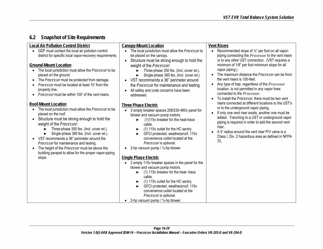
6.2 Snapshot of Site Requirements Local Air Pollution Control District • GDF must contact the local air pollution control
district for specific local vapor-recovery requirements.
Ground-Mount Location • The local jurisdiction must allow the Processor to be
placed on the ground. • The Processor must be protected from damage. • Processor must be located at least 10’ from the
property line. • Processor must be within 100’ of the vent risers.
Roof-Mount Location • The local jurisdiction must allow the Processor to be
placed on the roof. • Structure must be strong enough to hold the
weight of the Processor: ► Three-phase 350 lbs. (Incl. cover wt.). ► Single-phase 385 lbs. (Incl. cover wt.).
• VST recommends a 36” perimeter around the Processor for maintenance and testing.
• The height of the Processor must be above the building parapet to allow for the proper vapor-piping slope.
Canopy-Mount Location • The local jurisdiction must allow the Processor to
be placed on the canopy. • Structure must be strong enough to hold the
weight of the Processor: ► Three-phase 350 lbs. (Incl. cover wt.). ► Single-phase 385 lbs. (Incl. cover wt.).
• VST recommends a 36” perimeter around the Processor for maintenance and testing.
• All safety and code concerns have been addressed.
Three Phase Electric • 3 empty breaker spaces 208/230-460v panel for
blower and vacuum pump motors. ► (1)115v breaker for the heat-trace
cable. ► (1) 115v outlet for the HC sentry. ► GFCI protected, weatherproof, 115v
convenience outlet located at the Processor is optional.
• 2-hp vacuum pump / ½-hp blower. Single Phase Electric • 2 empty 115v breaker spaces in the panel for the
blower and vacuum pump motors. ► (1) 115v breaker for the heat- trace
cable. ► (1) 115v outlet for the HC sentry. ► GFCI protected, weatherproof, 115v
convenience outlet located at the Processor is optional.
• 2-hp vacuum pump / ½-hp blower.
Vent Risers • Recommended slope of ¼” per foot on all vapor-
piping connecting the Processor to the vent risers or to any other UST connection. (VST requires a minimum of 1/8” per foot minimum slope for all vapor piping.)
• The maximum distance the Processor can be from the vent risers is 100-feet.
• Any type of trap, regardless of the Processor location, is not permitted in any vapor lines connected to the Processor.
• To install the Processor, there must be two vent risers connected at different locations to the UST’s or to the underground vapor piping.
• If only one vent riser exists, another one must be added. Trenching to a UST or underground vapor piping is required in order to add the second vent riser.
• A 5’ radius around the vent riser P/V valve is a Class I, Div. 2 hazardous area as defined in NFPA 70.
VST EVR Total Balance System Solution
Page 14-30 Version 1.0(i) ARB Approved IOM-14 – Processor Installation Manual – Executive Orders VR-203-D and VR-204-D
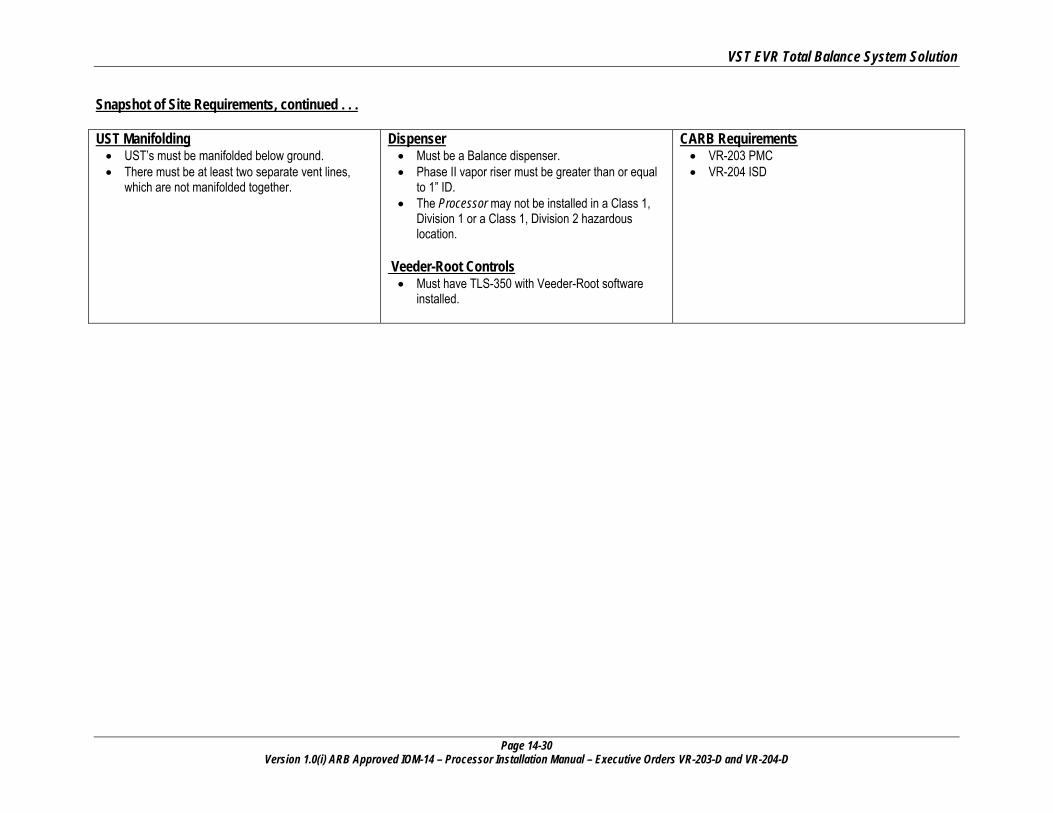
Snapshot of Site Requirements, continued . . . UST Manifolding • UST’s must be manifolded below ground. • There must be at least two separate vent lines,
which are not manifolded together.
Dispenser • Must be a Balance dispenser. • Phase II vapor riser must be greater than or equal
to 1” ID. • The Processor may not be installed in a Class 1,
Division 1 or a Class 1, Division 2 hazardous location.
Veeder-Root Controls • Must have TLS-350 with Veeder-Root software
installed.
CARB Requirements • VR-203 PMC • VR-204 ISD
VST EVR Total Balance System Solution
Page 14-31 Version 1.0(i) ARB Approved IOM-14 – Processor Installation Manual – Executive Orders VR-203-D and VR-204-D
7 Ground Installation
7.1 Ground Installation Safety
• The Processor will be installed near locations where highly flammable and explosive gasoline vapors may be present.
• Installation of the ECS Membrane Processor must comply with the National Electric Code, federal, state and local codes, as well as other applicable safety codes.
• Use extreme caution due to the risk of fire or explosion, which could result in serious injury or even death.
• If you are working in an area where vehicle traffic may occur, always block off the work area during installation, testing, and service to protect yourself and others.
• Do not use power tools that can generate sparks if there is a risk of flammable or explosive vapors being present.
• Read and understand all materials related to installing, testing, and operating the Processor prior to installation.
7.2 Protecting the Processor • Take measures to protect the Processor and external vapor piping from damage in areas near vehicle traffic
with guards, such as concrete-filled bollards or guardrails. ► Check local codes for protective-device guidelines before setting the bollards or guardrails.
• A fence should not be required since there is a lockable cover on the Processor with lockable hasps to prevent tampering. The contractor will provide the locks for the hasps.
• VST requires lockable ball valves be used at the inlet and outlet connections at the Processor. ► VST does not include any locks or lockable valves for the Processor; therefore, the contractor must provide them.
► Lockable ball valves used in this application must be compatible with gasoline and gasoline vapor. For further
requirements, consult the lockable-valve installation instructions provided by the manufacturer.
• The Processor cover is designed and built to withstand snow accumulation, rain, and landscaping sprinklers.

VST EVR Total Balance System Solution
Page 14-32 Version 1.0(i) ARB Approved IOM-14 – Processor Installation Manual – Executive Orders VR-203-D and VR-204-D
C A U T I O N Always obtain approval from the local authority having jurisdiction. Installation of the Processor must comply with (if applicable): • CARB CP-201 • VST EVR E.O. • Fire Marshall • Water Board • Local Air Pollution
District • ICC • NEC • NFPA 30 and 30A • UL • Any other applicable
federal, state, and local codes
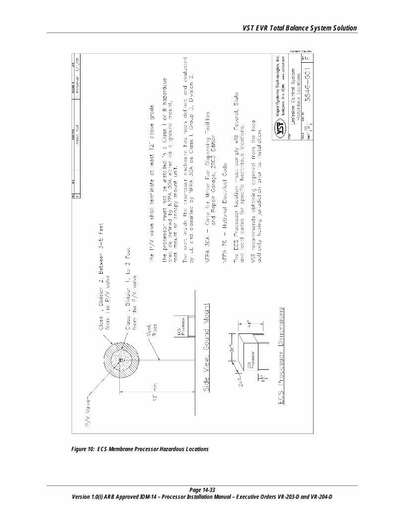
7.3 Ground-Mount Location • Location to property line: according to NFPA 30A, Section 10.1.7.1
“. . . in no case shall the vapor-processing equipment so protected be located within 3m (10-feet) of adjacent property lines that can be built upon.” ► Local authorities may grant reduced distance depending on the specific circumstances
• To minimize the installation cost and to maximize operating efficiency, locate the Processor adjacent to the existing vent risers.
• All vapor-piping connecting to the Processor must be sloped away from the Processor. VST recommends ¼” per foot slope. (VST requires a minimum of 1/8” per foot slope.)
• The Processor must be installed in accordance with the NEC and the NFPA standards.
• VST recommends a minimum clearance of 36” around the Processor for maintenance and testing.
• A new air outlet vent riser connected to the Processor must be installed to release air to the atmosphere.
• See Figure 5: Page 14-21.
VST EVR Total Balance System Solution
Page 14-33 Version 1.0(i) ARB Approved IOM-14 – Processor Installation Manual – Executive Orders VR-203-D and VR-204-D
Figure 10: ECS Membrane Processor Hazardous Locations
VST EVR Total Balance System Solution
Page 14-34 Version 1.0(i) ARB Approved IOM-14 – Processor Installation Manual – Executive Orders VR-203-D and VR-204-D
7.4 Setting the Concrete Pad • The Processor must be installed on a concrete pad, on grade, and permanently anchored to the concrete
pad.
• The Processor CANNOT be installed directly on or anchored directly to asphalt. It must be installed and anchored directly to a concrete pad.
• The Processor can be installed on existing concrete, provided: ► The existing concrete is of sufficient strength and thickness to support the Processor.
▪ VST recommends a minimum of 4-inch thick concrete to accommodate 3 1/2” expansion-type anchor bolts. ▪ Cracked concrete without re-bar may NOT be of sufficient strength to properly support the Processor.
► The Processor is installed level.
• NOTE: VST CANNOT BE HELD RESPONSIBLE FOR DAMAGE CAUSED BY IMPROPER PROCESSOR FOUNDATION SUPPORT.
• VST does not provide any hardware to install the Processor on the pad.
• VST recommends using the minimum clearances listed below for maintenance and service: ► Back: 36” ► Front: 36” ► Left: 36” ► Right: 36”
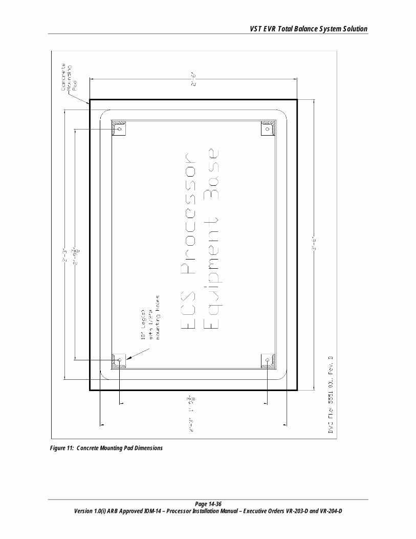
• Concrete pad minimum dimensions: ► 3’6” long x 2’6” wide ► 6” thick (minimum) ► See figure 11: Page 14-36.
• Use steel re-enforced rebar in the pad for additional strength.
• Install the pad level.
• Install expansion-type bolts after completing the concrete pad. The bolts must be: ► 3/8” diameter ► Embedded 3 ½” to 4” into the slab ► Extend approx. 1 ½” above the top of the slab
7.4.1 Processor Weight and Dimensions
Part Number Unit Dimensions Weight
VST-ECS-CS3-110 Single-Phase L-39” x W-27” x H-43” Height includes 18” legs
385 lbs. Includes 24-lb. cover
VST-ECS-CS3-310 Three-Phase L-39” x W-27” x H-43” Height includes 18” legs
350 lbs. Includes 24-lb. cover

VST EVR Total Balance System Solution
Page 14-35 Version 1.0(i) ARB Approved IOM-14 – Processor Installation Manual – Executive Orders VR-203-D and VR-204-D
7.5 Installing the Processor on the Concrete Pad
1 After the concrete has properly cured, install the expansion anchor bolts according to the manufacturer’s recommendations.
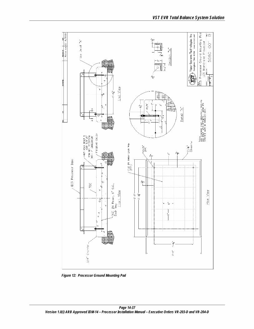
2 For non-seismic applications, VST recommends using the HILTI KWIK BOLT, KB3 3/8” X 5” / item #00282524 as shown in Figure 12: 14-37 or an approved equal.
3
For applications that require expansion anchors that are especially suited to seismic and cracked concrete, VST recommends using the HILTI KWIK TZ (KB-TZ) BOLT, KB-TZ 3/8” X 5”, (item number 00304583) or approved equal.
► The contractor or design engineer is responsible for sizing the expansion anchors and the concrete pad to meet seismic and cracked concrete specifications required by local, state, and federal jurisdictions.
► Since seismic regulations may be different by location, VST has not included a specific drawing for this application.
► For seismic design reference, www.us.hilti.com.
4 After the appropriate anchor bolts have been installed, position the Processor onto the anchor bolts in the cement slab.
5 Bolt the Processor into place (according to the manufacturer recommended installation guidelines) with 3/8” galvanized lock washers and bolts that are included with the expansion bolt.
VST EVR Total Balance System Solution
Page 14-36 Version 1.0(i) ARB Approved IOM-14 – Processor Installation Manual – Executive Orders VR-203-D and VR-204-D
Figure 11: Concrete Mounting Pad Dimensions
VST EVR Total Balance System Solution
Page 14-37 Version 1.0(i) ARB Approved IOM-14 – Processor Installation Manual – Executive Orders VR-203-D and VR-204-D
Figure 12: Processor Ground Mounting Pad
VST EVR Total Balance System Solution
Page 14-38 Version 1.0(i) ARB Approved IOM-14 – Processor Installation Manual – Executive Orders VR-203-D and VR-204-D
C A U T I O N Always obtain approval from the local authority having jurisdiction. Installation of the Processor must comply with (if applicable): • CARB CP-201 • VST EVR E.O. • Fire Marshall • Water Board • Local Air Pollution
District • ICC • NEC • NFPA 30 and 30A • UL • Any other applicable
federal, state, and local codes
8 Roof-Top Installation
8.1 Roof-Top Installation Safety
• The Processor will be installed near locations where highly flammable and explosive gasoline vapors may be present.
• Installation of the ECS Membrane Processor must comply with the National Electric Code, federal, state and local codes, as well as other applicable safety codes.
• Use extreme caution due to the risk of fire or explosion, which could result in serious injury or even death.
• If you are working in an area where vehicle traffic may occur, always block off the work area during installation, testing, and service to protect yourself and others.
• Do not use power tools that can generate sparks if there is a risk of flammable or explosive vapors being present.
• Read and understand all materials related to installing, testing, and operating the Processor prior to installation.
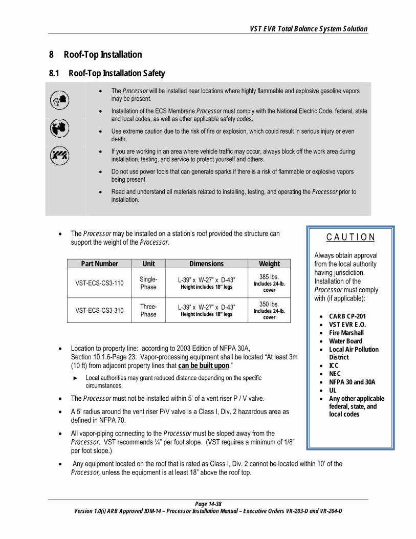
• The Processor may be installed on a station’s roof provided the structure can support the weight of the Processor.
Part Number Unit Dimensions Weight
VST-ECS-CS3-110 Single-Phase
L-39” x W-27” x D-43” Height includes 18” legs
385 lbs. Includes 24-lb.
cover
VST-ECS-CS3-310 Three-Phase
L-39” x W-27” x D-43” Height includes 18” legs
350 lbs. Includes 24-lb.
cover
• Location to property line: according to 2003 Edition of NFPA 30A, Section 10.1.6-Page 23: Vapor-processing equipment shall be located “At least 3m (10 ft) from adjacent property lines that can be built upon.” ► Local authorities may grant reduced distance depending on the specific
circumstances.
• The Processor must not be installed within 5’ of a vent riser P / V valve.
• A 5’ radius around the vent riser P/V valve is a Class I, Div. 2 hazardous area as defined in NFPA 70.
• All vapor-piping connecting to the Processor must be sloped away from the Processor. VST recommends ¼” per foot slope. (VST requires a minimum of 1/8” per foot slope.)
• Any equipment located on the roof that is rated as Class I, Div. 2 cannot be located within 10’ of the Processor, unless the equipment is at least 18” above the roof top.

VST EVR Total Balance System Solution
Page 14-39 Version 1.0(i) ARB Approved IOM-14 – Processor Installation Manual – Executive Orders VR-203-D and VR-204-D
• The Processor must be installed in accordance with the NEC and the NFPA standards.
• VST recommends a minimum clearance of 36” around the Processor for maintenance and testing.
• Due to a variety of roof construction designs, VST cannot recommend how the Processor should be mounted on the roof; however, the Processor must be installed at a height allowing the piping inlet and outlets to be above the building parapet.
• The Processor is shipped on 18” legs bolted on the base, but the legs may be removed and the Processor secured to a steel structure attached to the roof.
• A new air outlet vent riser connected to the Processor must be installed to release air to the atmosphere.

VST EVR Total Balance System Solution
Page 14-40 Version 1.0(i) ARB Approved IOM-14 – Processor Installation Manual – Executive Orders VR-203-D and VR-204-D
C A U T I O N Always obtain approval from the local authority having jurisdiction. Installation of the Processor must comply with (if applicable): • CARB CP-201 • VST EVR E.O. • Fire Marshall • Water Board • Local Air Pollution
District • ICC • NEC • NFPA 30 and 30A • UL • Any other applicable
federal, state, and local codes
9 Canopy Top Installation
9.1 Canopy Top Installation Safety
• The Processor will be installed near locations where highly flammable and explosive gasoline vapors may be present.
• Installation of the ECS Membrane Processor must comply with the National Electric Code, federal, state and local codes, as well as other applicable safety codes.
• Use extreme caution due to the risk of fire or explosion which could result in serious injury or even death.
• If you are working in an area where vehicle traffic may occur, always block off the work area during installation, testing, and service to protect yourself and others.
• Do not use power tools that can generate sparks if there is a risk of flammable or explosive vapors being present.
• Read and understand all materials related to installing, testing, and operating the Processor prior to installation.
• The Processor may be installed on a station’s canopy provided the structure can support the weight of the Processor.
Part Number Unit Dimensions Weight
VST-ECS-CS3-110 Single-Phase
L-39” x W-27” x D-43” Height includes 18” legs
385 lbs. Includes 24-lb.
cover
VST-ECS-CS3-310 Three-Phase
L-39” x W-27” x D-43” Height includes 18” legs
350 lbs. Includes 24-lb.
cover
• Location to property line: according to 2003 Edition of NFPA 30A, Section 10.1.6, Page 23: Vapor-processing equipment shall be located ► “At least 3m (10 ft) from adjacent property lines that can be built upon.”
Local authorities may grant reduced distance depending on the specific circumstances.
• The Processor cannot be installed within 5’ of a vent riser P / V valve.
• A 5’ radius around the vent riser P/V valve is a Class I, Div. 2 hazardous area as defined in NFPA 70.
• All vapor-piping connecting to the Processor must be sloped away from the Processor. VST recommends ¼” per foot slope. (VST requires a minimum of 1/8” per foot slope).
• The Processor must be installed in accordance with the NEC and the NFPA standards.
VST EVR Total Balance System Solution
Page 14-41 Version 1.0(i) ARB Approved IOM-14 – Processor Installation Manual – Executive Orders VR-203-D and VR-204-D
• VST recommends a minimum clearance of 36” around the Processor for maintenance and testing.
• Due to a variety of canopy construction designs, VST cannot recommend how the Processor should be mounted on the canopy.
• All safety and code concerns should be taken into consideration prior to a canopy-top installation.
• The Processor is shipped on 18” legs bolted on the base, but the legs may be removed and the Processor secured to a steel structure attached to the canopy or to the roof top. NOTE: THE MINIMUM PIPING SLOPE MUST ALWAYS BE MAINTAINED.
• A new air outlet vent riser connected to the Processor must be installed to release air to the atmosphere.
VST EVR Total Balance System Solution
Page 14-42 Version 1.0(i) ARB Approved IOM-14 – Processor Installation Manual – Executive Orders VR-203-D and VR-204-D
C A U T I O N Always obtain approval from the local authority having jurisdiction. Installation of the Processor must comply with (if applicable): • CARB CP-201 • VST EVR E.O. • Fire Marshall • Water Board • Local Air Pollution
District • ICC • NEC • NFPA 30 and 30A • UL • Any other applicable
federal, state, and local codes
10 Vapor Piping
10.1 Vapor Piping Safety
• The Processor will be installed near locations where highly flammable and explosive
gasoline vapors may be present. • Installation of the ECS Membrane Processor must comply with the National Electric Code,
federal, state and local codes, as well as other applicable safety codes. • Use extreme caution due to the risk of fire or explosion which could result in serious injury
or even death. • If you are working in an area where vehicle traffic may occur, always block off the work
area during installation, testing, and service to protect yourself and others. • Do not use power tools that can generate sparks if there is a risk of flammable or
explosive vapors being present. • Read and understand all materials related to installing, testing, and operating the
Processor prior to installation.
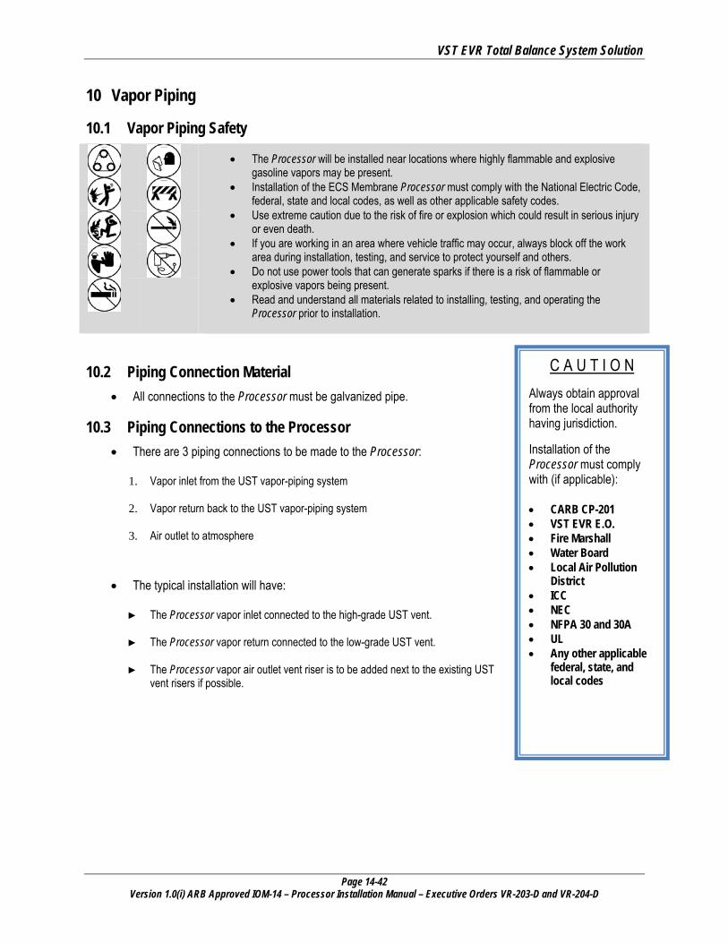
10.2 Piping Connection Material • All connections to the Processor must be galvanized pipe.
10.3 Piping Connections to the Processor • There are 3 piping connections to be made to the Processor:
1. Vapor inlet from the UST vapor-piping system
2. Vapor return back to the UST vapor-piping system
3. Air outlet to atmosphere
• The typical installation will have: ► The Processor vapor inlet connected to the high-grade UST vent.
► The Processor vapor return connected to the low-grade UST vent.
► The Processor vapor air outlet vent riser is to be added next to the existing UST
vent risers if possible.

VST EVR Total Balance System Solution
Page 14-43 Version 1.0(i) ARB Approved IOM-14 – Processor Installation Manual – Executive Orders VR-203-D and VR-204-D
10.3.1 Flexible Connections • Flexible connections between the Processor locking ball and the vent riser(s) are allowable if required by
the local Authority Having Jurisdiction to meet seismic requirements.
• Should the flex connection be installed such that it is not supported, the slope of the flex connection from the Processor back to the vent riser(s) shall be greater than the 1/8” / foot slope required for the rest of the one-inch galvanized piping.
• The flexible connector must be UL approved for a service station above-ground application.
• The local contractor is responsible to provide all necessary galvanized piping, non-hardening UL-classified pipe joint compound and plumbing fittings.
• This requirement may apply for ground, rooftop, and canopy-mount locations.
10.4 Trenching • The Processor may be installed without any trenching provided:
► There are at least 2 vent risers connected to the UST’s.
► The vent-riser piping connecting to the UST’s will not short circuit the Processor.
• Trenching will be required if only one vent riser exists at the GDF to connect the Processor to the UST’s. ► When one vent riser exists at a GDF, trenching is required to return the concentrated vapor from the Processor to
the UST’s.
► The existing vent riser will be used as the “Vapor Inlet” connection to the Processor.
► A new vent riser must be installed that connects the Processor to the UST’s.
▪ The connection pipe must be a minimum of 2” ID for all underground piping. ▪ All new piping must be sloped back to the UST’s. ▪ VST recommends a ¼” per foot slope away from the Processor for all vapor piping connecting the Processor
to the UST vent risers or to any other UST connection points. A minimum of 1/8” slope is required by VST. ▪ The connection location to the UST’s must be configured to prevent short-circuit of the inlet vapor piping to
the Processor. ▪ The connection should be used as the “Vapor Return” piping returning the concentrated vapor from the
Processor to the Low Octane UST.

VST EVR Total Balance System Solution
Page 14-44 Version 1.0(i) ARB Approved IOM-14 – Processor Installation Manual – Executive Orders VR-203-D and VR-204-D
C A U T I O N
Always obtain approval from the local authority having jurisdiction. Installation of the Processor must comply with (if applicable): • CARB CP-201
• VST EVR E.O.
• Fire Marshall
• Water Board
• Local Air Pollution
District
• ICC
• NEC
• NFPA 30 and 30A
• UL
• Any other applicable federal, state, and local codes
10.5 Underground Vapor Piping Instructions • From the dispenser to the UST:
► A minimum of 2” ID is acceptable unless the dispenser lines are
manifolded together.
► Manifolded dispenser lines require a minimum 3” ID piping, including the float-vent valve, if applicable.
► Check the “Vapor-Recovery Piping Configurations” section of Exhibit 2 for Underground Piping Requirements.
• From the UST to the vent riser ► Stations that use only one vent riser require a minimum of 3” ID vapor
piping and will require trenching as well.
► Stations that use multiple risers require a minimum of 2” ID vapor piping.
• From the Processor vapor return to the UST ► When new underground piping is required from the Processor vapor return to the
low octane UST, VST requires a minimum of 2” ID piping.
VST EVR Total Balance System Solution
Page 14-45 Version 1.0(i) ARB Approved IOM-14 – Processor Installation Manual – Executive Orders VR-203-D and VR-204-D
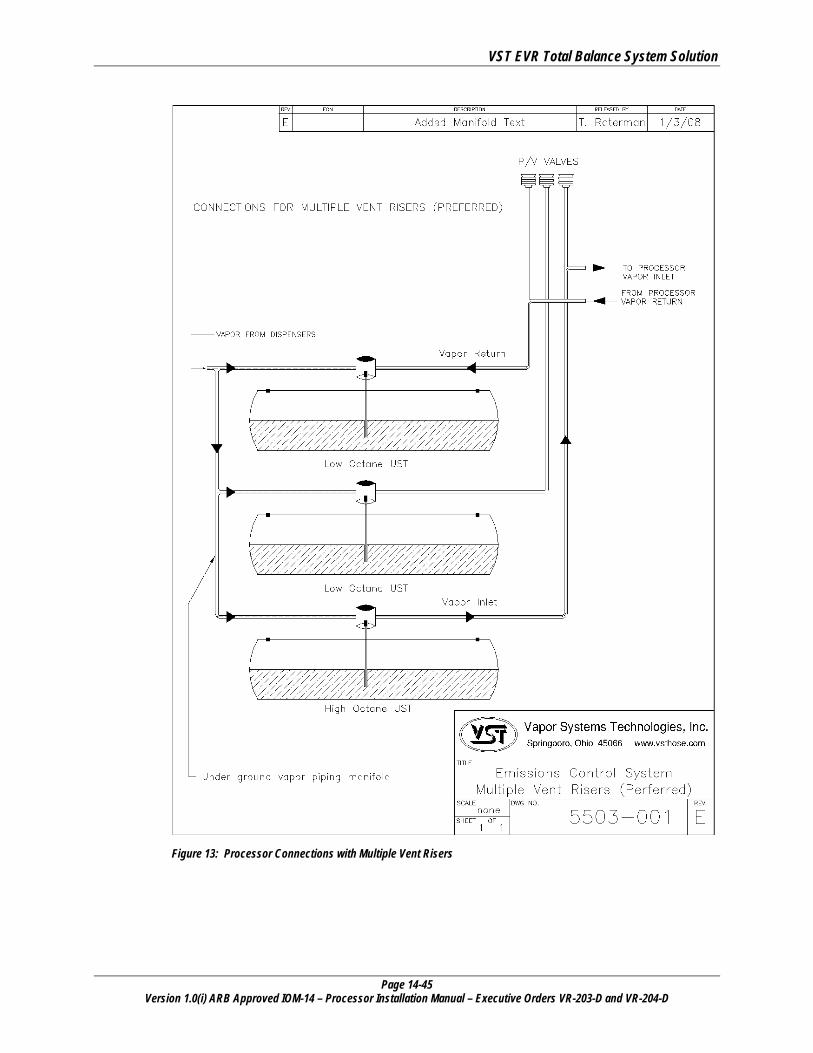
Figure 13: Processor Connections with Multiple Vent Risers
VST EVR Total Balance System Solution
Page 14-46 Version 1.0(i) ARB Approved IOM-14 – Processor Installation Manual – Executive Orders VR-203-D and VR-204-D
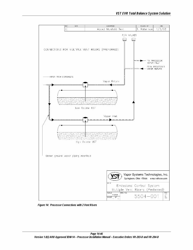
Figure 14: Processor Connections with 2 Vent Risers
VST EVR Total Balance System Solution
Page 14-47 Version 1.0(i) ARB Approved IOM-14 – Processor Installation Manual – Executive Orders VR-203-D and VR-204-D
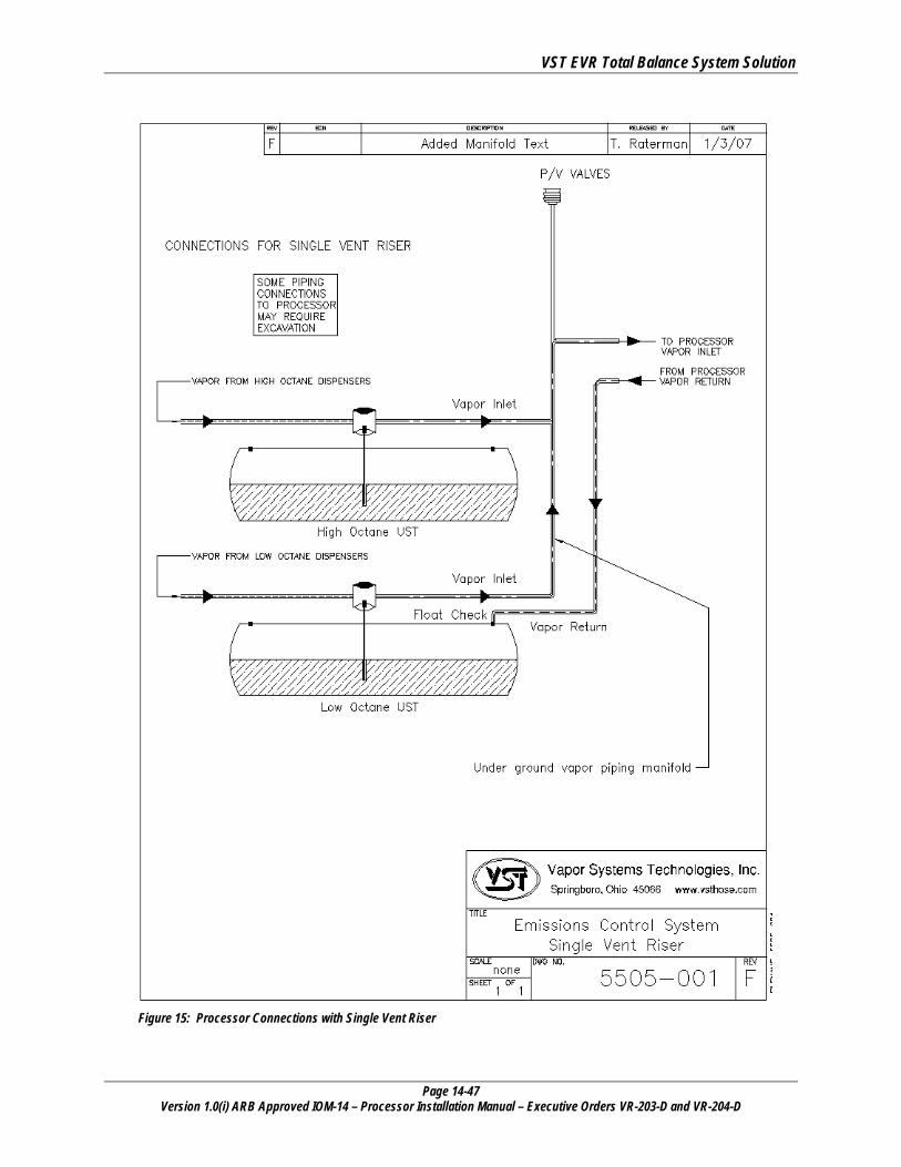
Figure 15: Processor Connections with Single Vent Riser
VST EVR Total Balance System Solution
Page 14-48 Version 1.0(i) ARB Approved IOM-14 – Processor Installation Manual – Executive Orders VR-203-D and VR-204-D
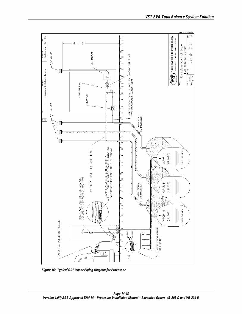
Figure 16: Typical GDF Vapor Piping Diagram for Processor
VST EVR Total Balance System Solution
Page 14-49 Version 1.0(i) ARB Approved IOM-14 – Processor Installation Manual – Executive Orders VR-203-D and VR-204-D
10.6 Vapor Inlet and Vapor Return Connections • Install a minimum 1” galvanized pipe between the Processor and the vent riser(s) if the distance between
the Processor and the vent riser is less than 10’.
• If the distance between the Processor and vent risers is greater than 10’, use a minimum 1 ½” diameter pipe.
• See Figure 17: Page 14-X for pipe size requirements.
• When new underground piping is required from the Processor to the low-octane UST, a minimum of 2” ID piping is required.
• Order of installation:
1. Processor 2. Tee (sized for the pipe diameter) 3. Ball Valve (sized for the pipe diameter) 4. Union (sized for the pipe diameter) 5. Vent Riser
• Provide a slope for the piping from the Processor of at least ¼” per foot.
► VST requires a minimum slope of 1/8” per foot.
• Verify that all piping connections are leak tight.
• Connect the vapor inlet and vapor return for the Processor to existing vent risers provided there are multiple vent risers connecting to individual USTs.
• Install new tees in the existing vent risers for connection to the Processor vapor inlet & outlet.
• Take note that pipe connecting vent risers to the Processor MUST slope away from the Processor towards the vent risers.
10.6.1 Flexible Connections • Flexible connections between the Processor locking ball and the vent riser(s) are allowable if required by
the local Authority Having Jurisdiction to meet seismic requirements.
• Should the flex connection be installed such that it is not supported, the slope of the flex connection from the Processor back to the vent riser(s) shall be greater than the 1/8” / foot slope required for the rest of the one-inch galvanized piping.
• The flexible connector must be UL approved for a service station above-ground application.
• The local contractor is responsible to provide all necessary galvanized piping, non-hardening UL-classified pipe joint compound and plumbing fittings.
• This requirement may apply for ground, rooftop, and canopy-mount locations.
The tee and the ball valve allow for isolation of the Processor from the vapor-piping system for maintenance and testing. See Figure 17: Page 14-52
VST EVR Total Balance System Solution
Page 14-50 Version 1.0(i) ARB Approved IOM-14 – Processor Installation Manual – Executive Orders VR-203-D and VR-204-D
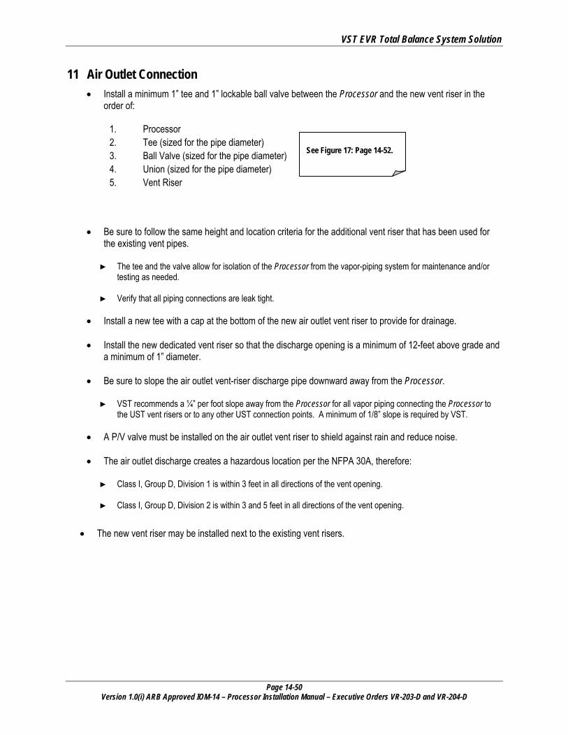
11 Air Outlet Connection • Install a minimum 1” tee and 1” lockable ball valve between the Processor and the new vent riser in the
order of:
1. Processor 2. Tee (sized for the pipe diameter) 3. Ball Valve (sized for the pipe diameter) 4. Union (sized for the pipe diameter) 5. Vent Riser
• Be sure to follow the same height and location criteria for the additional vent riser that has been used for the existing vent pipes. ► The tee and the valve allow for isolation of the Processor from the vapor-piping system for maintenance and/or
testing as needed.
► Verify that all piping connections are leak tight.
• Install a new tee with a cap at the bottom of the new air outlet vent riser to provide for drainage.
• Install the new dedicated vent riser so that the discharge opening is a minimum of 12-feet above grade and a minimum of 1” diameter.
• Be sure to slope the air outlet vent-riser discharge pipe downward away from the Processor. ► VST recommends a ¼” per foot slope away from the Processor for all vapor piping connecting the Processor to
the UST vent risers or to any other UST connection points. A minimum of 1/8” slope is required by VST.
• A P/V valve must be installed on the air outlet vent riser to shield against rain and reduce noise.
• The air outlet discharge creates a hazardous location per the NFPA 30A, therefore: ► Class I, Group D, Division 1 is within 3 feet in all directions of the vent opening.
► Class I, Group D, Division 2 is within 3 and 5 feet in all directions of the vent opening.
• The new vent riser may be installed next to the existing vent risers.
See Figure 17: Page 14-52.
VST EVR Total Balance System Solution
Page 14-51 Version 1.0(i) ARB Approved IOM-14 – Processor Installation Manual – Executive Orders VR-203-D and VR-204-D
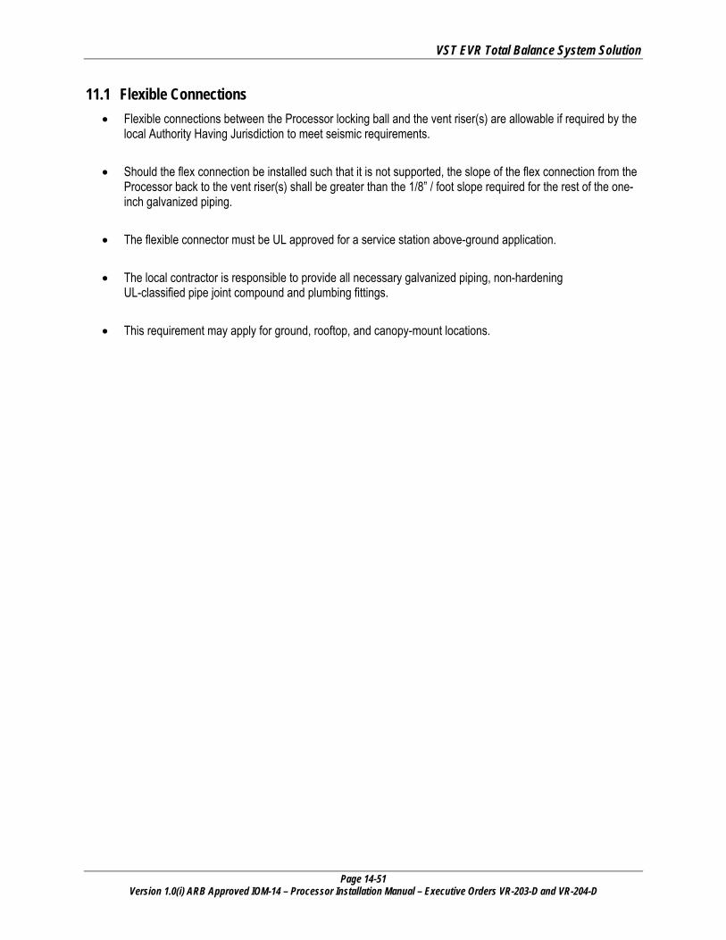
11.1 Flexible Connections • Flexible connections between the Processor locking ball and the vent riser(s) are allowable if required by the
local Authority Having Jurisdiction to meet seismic requirements.
• Should the flex connection be installed such that it is not supported, the slope of the flex connection from the Processor back to the vent riser(s) shall be greater than the 1/8” / foot slope required for the rest of the one-inch galvanized piping.
• The flexible connector must be UL approved for a service station above-ground application.
• The local contractor is responsible to provide all necessary galvanized piping, non-hardening UL-classified pipe joint compound and plumbing fittings.
• This requirement may apply for ground, rooftop, and canopy-mount locations.
VST EVR Total Balance System Solution
Page 14-52 Version 1.0(i) ARB Approved IOM-14 – Processor Installation Manual – Executive Orders VR-203-D and VR-204-D
Figure 17: ECS Processor Piping Diagram
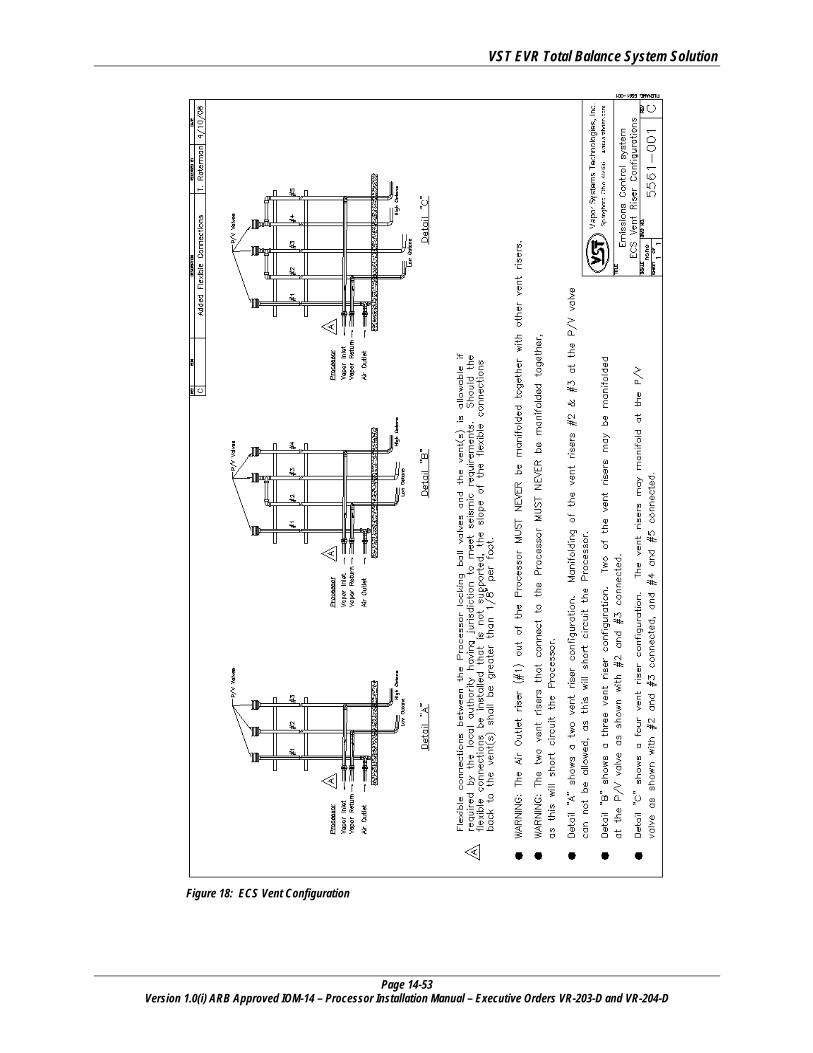
VST EVR Total Balance System Solution
Page 14-53 Version 1.0(i) ARB Approved IOM-14 – Processor Installation Manual – Executive Orders VR-203-D and VR-204-D
Figure 18: ECS Vent Configuration
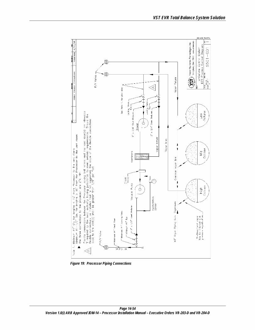
VST EVR Total Balance System Solution
Page 14-54 Version 1.0(i) ARB Approved IOM-14 – Processor Installation Manual – Executive Orders VR-203-D and VR-204-D
Figure 19: Processor Piping Connections
VST EVR Total Balance System Solution
Page 14-55 Version 1.0(i) ARB Approved IOM-14 – Processor Installation Manual – Executive Orders VR-203-D and VR-204-D
C A U T I O N
Always obtain approval from the local authority having jurisdiction. Installation of the Processor must comply with (if applicable): • CARB CP-201
• VST EVR E.O.
• Fire Marshall
• Water Board
• Local Air Pollution
District
• ICC
• NEC
• NFPA 30 and 30A
• UL
• Any other applicable federal, state, and local codes
11.2 Underground Piping Connection • Provide a slope for the vapor piping for drainage. VST recommends a ¼” per foot slope for all vapor piping.
A minimum of 1/8” slope is required by VST.
• Meet all CP-201 size and slope requirements for all underground piping. ► To avoid the possibility of an underground liquid trap, never use flexible vapor piping.
• All underground vapor piping must be a minimum of 2” NPT. ► Always check with local authorities for applicable requirements; larger pipe size may
be required.
• Refer to pipe-size requirements in Exhibit 2, Executive Orders VR/203 and VR/204.
11.3 Storage Tank Vapor Manifolds • Storage tanks must be vapor manifolded below ground.
11.4 P / V Valves • All of the vent risers, including the additional vent risers for the Processor air
outlet, must have a P/V valve installed.
• The air outlet P/V valve (functional or non-functional) is not regulated by CARB and does not need to be tested by AQMD’s.
• The P/V valve for each vent riser (not including the Processor air outlet) is part of the Phase I system, and therefore must be a CARB-certified component.
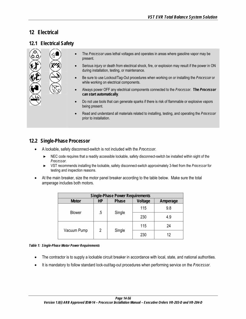
VST EVR Total Balance System Solution
Page 14-56 Version 1.0(i) ARB Approved IOM-14 – Processor Installation Manual – Executive Orders VR-203-D and VR-204-D
12 Electrical
12.1 Electrical Safety
• The Processor uses lethal voltages and operates in areas where gasoline vapor may be
present.
• Serious injury or death from electrical shock, fire, or explosion may result if the power in ON during installation, testing, or maintenance.
• Be sure to use Lockout/Tag-Out procedures when working on or installing the Processor or while working on electrical components.
• Always power OFF any electrical components connected to the Processor. The Processor can start automatically.
• Do not use tools that can generate sparks if there is risk of flammable or explosive vapors being present.
• Read and understand all materials related to installing, testing, and operating the Processor prior to installation.
12.2 Single-Phase Processor • A lockable, safety disconnect-switch is not included with the Processor.
► NEC code requires that a readily accessible lockable, safety disconnect-switch be installed within sight of the Processor.
► VST recommends installing the lockable, safety disconnect-switch approximately 3-feet from the Processor for testing and inspection reasons.
• At the main breaker, size the motor panel breaker according to the table below. Make sure the total amperage includes both motors.
Single-Phase Power Requirements Motor HP Phase Voltage Amperage
Blower .5 Single 115 9.8
230 4.9
Vacuum Pump 2 Single 115 24
230 12 Table 1: Single-Phase Motor Power Requirements
• The contractor is to supply a lockable circuit breaker in accordance with local, state, and national authorities.
• It is mandatory to follow standard lock-out/tag-out procedures when performing service on the Processor.
VST EVR Total Balance System Solution
Page 14-57 Version 1.0(i) ARB Approved IOM-14 – Processor Installation Manual – Executive Orders VR-203-D and VR-204-D
• Following such procedures may be required by local, state, and national authorities. ► You must install the Processor in accordance with the National Electric Code (NEC), NFPA 70, and with the
Automotive and Marine Service Station Code (NFPA30A). ► According to NFPA 30A and the California Fire Code:
“Electrically energized vapor-recovery equipment shall be directly connected to and controlled by the emergency pump shut off in Section 5202.4.7.” See figure 22: Page 14-67.
• The contractor shall supply 115v motor starter(s) with a 115v relay coil to start/stop the single-phase motors.
12.2.1 Power Requirements for Single-Phase Electrical Service
• 115v/230v, single-phase, 60Hz (blower and vacuum pump motors). ► See Table 1: Page 14-56 for the motor amperage.
• 115v breaker (heat-trace cable power). ► 115v, 2-amp service to power the heat trace.
• 115v, 2-amp minimum service to power a dedicated outlet for the 24VDC power supply for the HC sensor and the HC sentry.
• The ECS motor-starter relay(s) connects to the TLS.
• The ECS motor-starter relay(s) can be located inside the GDF or at the Processor, depending on the electrical design.
12.3 Three-Phase Processor • A circuit disconnect device is not included with the Processor.
► NEC code requires that a readily accessible lockable, safety disconnect-switch be installed within sight of the Processor.
► VST recommends installing the lockable, safety disconnect-switch approximately 3-feet from the Processor for testing and inspection reasons.
• At the main breaker use a 208/230-460v, 3-phase, 60Hz electric service. ► See Table 2: Page 14-58 for the motor amperage.
• The contractor is to supply a lockable circuit breaker in accordance with local, state, and national authorities. ► It is mandatory practice to follow standard lock-out / tag-out procedures when performing service on the unit.
• Following such procedures may be required by local, state, and national authorities. ► You must install the Processor in accordance with the National Electric Code (NEC), NFPA 70, and with the
Automotive and Marine Service Station Code (NFPA30A).
► According to NFPA 30A and the California Fire Code: “Electrically energized vapor-recovery equipment shall be directly connected to and controlled by the emergency pump shut off in Section 5202.4.7.” See figure 27: Page 14-72.
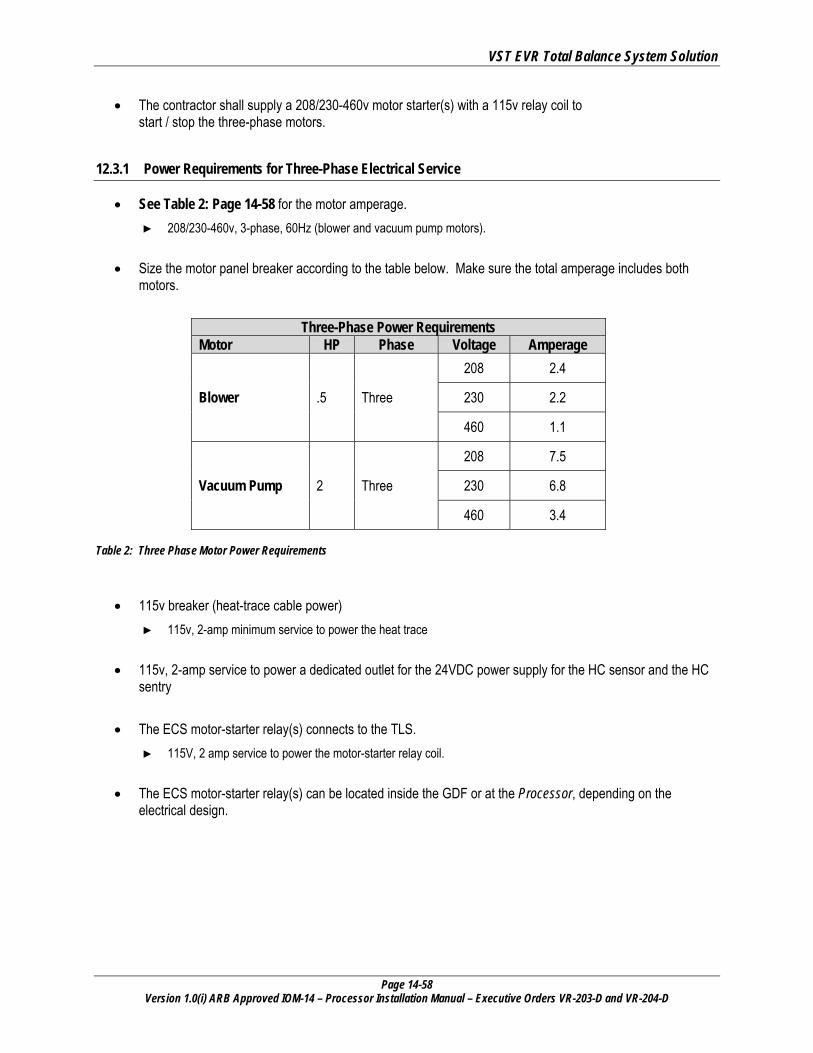
VST EVR Total Balance System Solution
Page 14-58 Version 1.0(i) ARB Approved IOM-14 – Processor Installation Manual – Executive Orders VR-203-D and VR-204-D
• The contractor shall supply a 208/230-460v motor starter(s) with a 115v relay coil to start / stop the three-phase motors.
12.3.1 Power Requirements for Three-Phase Electrical Service
• See Table 2: Page 14-58 for the motor amperage. ► 208/230-460v, 3-phase, 60Hz (blower and vacuum pump motors).
• Size the motor panel breaker according to the table below. Make sure the total amperage includes both motors.
Three-Phase Power Requirements Motor HP Phase Voltage Amperage
Blower .5 Three
208 2.4
230 2.2
460 1.1
Vacuum Pump 2 Three
208 7.5
230 6.8
460 3.4 Table 2: Three Phase Motor Power Requirements
• 115v breaker (heat-trace cable power) ► 115v, 2-amp minimum service to power the heat trace
• 115v, 2-amp service to power a dedicated outlet for the 24VDC power supply for the HC sensor and the HC sentry
• The ECS motor-starter relay(s) connects to the TLS. ► 115V, 2 amp service to power the motor-starter relay coil.
• The ECS motor-starter relay(s) can be located inside the GDF or at the Processor, depending on the electrical design.
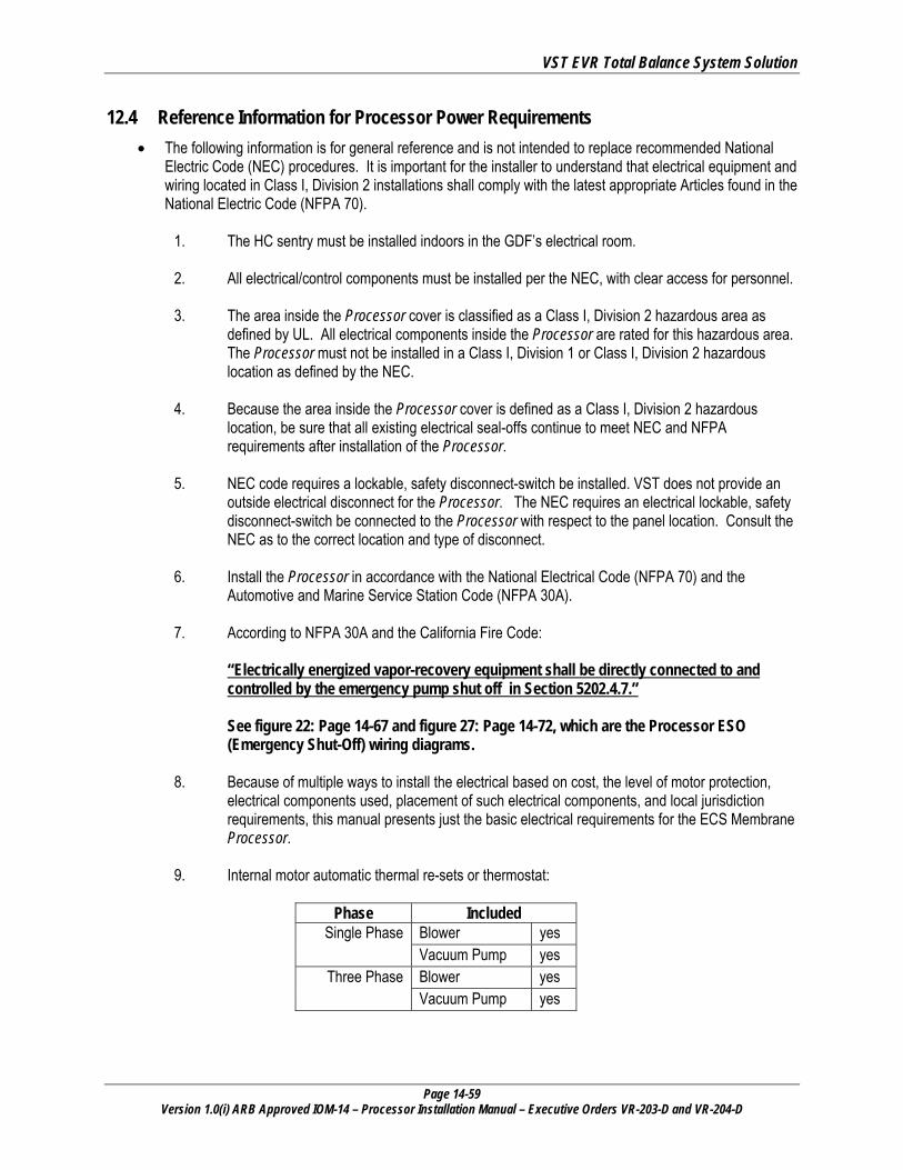
VST EVR Total Balance System Solution
Page 14-59 Version 1.0(i) ARB Approved IOM-14 – Processor Installation Manual – Executive Orders VR-203-D and VR-204-D
12.4 Reference Information for Processor Power Requirements • The following information is for general reference and is not intended to replace recommended National
Electric Code (NEC) procedures. It is important for the installer to understand that electrical equipment and wiring located in Class I, Division 2 installations shall comply with the latest appropriate Articles found in the National Electric Code (NFPA 70).
1. The HC sentry must be installed indoors in the GDF’s electrical room.
2. All electrical/control components must be installed per the NEC, with clear access for personnel.
3. The area inside the Processor cover is classified as a Class I, Division 2 hazardous area as
defined by UL. All electrical components inside the Processor are rated for this hazardous area. The Processor must not be installed in a Class I, Division 1 or Class I, Division 2 hazardous location as defined by the NEC.
4. Because the area inside the Processor cover is defined as a Class I, Division 2 hazardous location, be sure that all existing electrical seal-offs continue to meet NEC and NFPA requirements after installation of the Processor.
5. NEC code requires a lockable, safety disconnect-switch be installed. VST does not provide an outside electrical disconnect for the Processor. The NEC requires an electrical lockable, safety disconnect-switch be connected to the Processor with respect to the panel location. Consult the NEC as to the correct location and type of disconnect.
6. Install the Processor in accordance with the National Electrical Code (NFPA 70) and the Automotive and Marine Service Station Code (NFPA 30A).
7. According to NFPA 30A and the California Fire Code: “Electrically energized vapor-recovery equipment shall be directly connected to and controlled by the emergency pump shut off in Section 5202.4.7.” See figure 22: Page 14-67 and figure 27: Page 14-72, which are the Processor ESO (Emergency Shut-Off) wiring diagrams.
8. Because of multiple ways to install the electrical based on cost, the level of motor protection, electrical components used, placement of such electrical components, and local jurisdiction requirements, this manual presents just the basic electrical requirements for the ECS Membrane Processor.
9. Internal motor automatic thermal re-sets or thermostat:
Phase Included Single Phase Blower yes
Vacuum Pump yes Three Phase Blower yes
Vacuum Pump yes
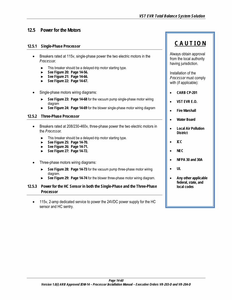
VST EVR Total Balance System Solution
Page 14-60 Version 1.0(i) ARB Approved IOM-14 – Processor Installation Manual – Executive Orders VR-203-D and VR-204-D
C A U T I O N
Always obtain approval from the local authority having jurisdiction. Installation of the Processor must comply with (if applicable): • CARB CP-201
• VST EVR E.O.
• Fire Marshall
• Water Board
• Local Air Pollution
District
• ICC
• NEC
• NFPA 30 and 30A
• UL • Any other applicable
federal, state, and local codes
12.5 Power for the Motors
12.5.1 Single-Phase Processor
• Breakers rated at 115v, single-phase power the two electric motors in the Processor. ► This breaker should be a delayed-trip motor starting type. ► See Figure 20: Page 14-56. ► See Figure 21: Page 14-66. ► See Figure 22: Page 14-67.
• Single-phase motors wiring diagrams: ► See Figure 23: Page 14-68 for the vacuum pump single-phase motor wiring
diagram ► See Figure 24: Page 14-69 for the blower single-phase motor wiring diagram
12.5.2 Three-Phase Processor
• Breakers rated at 208/230-460v, three-phase power the two electric motors in the Processor. ► This breaker should be a delayed-trip motor starting type. ► See Figure 25: Page 14-70. ► See Figure 26: Page 14-71. ► See Figure 27: Page 14-72.
• Three-phase motors wiring diagrams: ► See Figure 28: Page 14-73 for the vacuum pump three-phase motor wiring
diagram. ► See Figure 29: Page 14-74 for the blower three-phase motor wiring diagram.
12.5.3 Power for the HC Sensor in both the Single-Phase and the Three-Phase Processor
• 115v, 2-amp dedicated service to power the 24VDC power supply for the HC sensor and HC sentry.
VST EVR Total Balance System Solution
Page 14-61 Version 1.0(i) ARB Approved IOM-14 – Processor Installation Manual – Executive Orders VR-203-D and VR-204-D
12.6 Power for the Heat-Trace Cables in both Single-Phase and Three-Phase Processors
• 115v circuit powers the heat-trace cable. ► The negative side of the circuit is off a common neutral with a common ground inside the electrical enclosure
located inside the Processor.
12.7 Power for the Motor Starter Relay Coil • 115v circuit provides power to the relay coil.
12.8 Optional Convenience Outlet at the Processor • An optional convenience outlet located near the Processor may be installed for powering tools and test
equipment.
CAUTION: The optional convenience outlet located near the Processor CANNOT be installed in a Class 1, Div. 2 hazardous area.
► The wires for the convenience outlet can go in the same conduit as the motor power wires.
• Seal-offs are required as per NFPA 70 for a conduit run leaving a Division 2 location to an unclassified location. ► Install as required by the NEC and local authority having jurisdiction.
• Other seal-offs may be necessary based on the installation and site specifics.
VST EVR Total Balance System Solution
Page 14-62 Version 1.0(i) ARB Approved IOM-14 – Processor Installation Manual – Executive Orders VR-203-D and VR-204-D
13 Electrical Installation
13.1 Electical Safety
• The Processor uses lethal voltages and operates in areas where gasoline vapor may be
present.
• Serious injury or death from electrical shock, fire, or explosion may result if the power in ON during installation, testing, or maintenance.
• Be sure to use Lockout/Tag-Out procedures when working on or installing the Processor or while working on electrical components.
• Always power OFF any electrical components connected to the Processor. The Processor can start automatically.
• Do not use tools that can generate sparks if there is risk of flammable or explosive vapors being present.
• Read and understand all materials related to installing, testing, and operating the Processor prior to installation.
13.2 Electrical Installation Code Requirements • According to NFPA 30:
“Electrical wiring and electrical utilization equipment shall be a type specified by and be installed in accordance with NFPA 70. Electrical wiring and electrical utilization equipment shall be approved for the locations in which they are installed.”
• All electrical wiring and electrical utilization equipment must be installed to meet federal, state, and local codes.
• Flexible electrical conduit connections to the Processor may be required by local jurisdictions to meet seismic code requirements.
13.2.1 Single-Phase Processor Configuration
• The ECS motor-starter relay can be installed inside the GDF’s electrical room or at the Processor, depending on the electrical design.
• Install properly-sized conduit from the electrical room to a lockable, safety disconnect-switch (located near the Processor).
• From the disconnect switch to the Processor: ► The first ¾” rigid conduit is for the 115v vacuum pump and blower motors. It is also for 115v power for the heat
trace cable. ► The second ¾” rigid conduit is for 24VDC and HC signal control wiring.
If you are using existing conduit, it is acceptable by VST to run the electrical and the communications through the same conduit, provided that the local jurisdiction authorizes doing so.
BE SURE TO CHECK WITH LOCAL AUTHORITIES.
VST EVR Total Balance System Solution
Page 14-63 Version 1.0(i) ARB Approved IOM-14 – Processor Installation Manual – Executive Orders VR-203-D and VR-204-D
13.2.2 Three-Phase Processor Configuration
• The ECS motor-starter relay can be installed inside the GDF’s electrical room or at the Processor, depending on the electrical design.
• Install properly-sized conduit from the electrical room to a lockable, safety disconnect-switch (located near the Processor).
• From the disconnect switch to the Processor: ► The first ¾” rigid conduit is for 208/230-460v vacuum pump and blower motors. It is also for 115v power for the
heat trace cable. ► The second ¾” rigid conduit is for 24VDC and HC signal control wiring.
If you are using existing conduit, it is acceptable by VST to run the electrical and the communications through the same conduit, provided that the local jurisdiction authorizes doing so.
BE SURE TO CHECK WITH LOCAL AUTHORITIES.
VST EVR Total Balance System Solution
Page 14-64 Version 1.0(i) ARB Approved IOM-14 – Processor Installation Manual – Executive Orders VR-203-D and VR-204-D
13.3 Single and Three-Phase Processors • Install the electrical / communications conduit(s) sized to meet NEC and local code standards from the
electrical room to a lockable, safety disconnect-switch. ► THE NEC REQUIRES THAT A LOCKABLE, SAFETY DISCONNECT-SWITCH BE LOCATED NEAR THE
PROCESSOR. ► Flexible electrical conduit connections to the Processor may be required by local jurisdictions to meet seismic
code requirements.
• Install either one or two ¾” diameter conduit connections on the Processor. ► There are two ¾” diameter conduit connections on the Processor. ► The contractor may decide to use either one or both of these conduits depending on:
▪ The configuration of the electrical switch ▪ Single phase or three phase Processor ▪ Size of the wire used in the Processor
13.3.1 Wiring between the Processor and components:
• All wiring (208/203-460 VAC and 24 VDC) to be TFFN or THHN with 600 V insulation.
• All wiring must be gasoline and oil resistant.
• VST provides the 24VDC power supply for the HC Sentry module. ► The 24VDC power-supply plugs into a dedicated 115v outlet. ► The 115v outlet must be located within 3-feet of the HC sentry module.
• The HC sensor receives 24VDC power from the HC sentry module, and the HC sentry module receives 4-20 mA control signal from the HC sensor. ► One cable contains the 24VDC power and 4-20 mA signals. ► The cable must be a minimum 3 conductor, 18 AWG, twisted pair with a shielded ground. ► The isolated ground is connected to the HC Sentry. The HC Sentry receives power from a separate 115V circuit.
• Run two ground wires from the electrical panel: ► 1st ground wire is the equipment ground. ► 2nd ground wire is an electrical ground. ► Both grounds must be a minimum 12 AWG (follow all NEC requirements for equipment grounding).
• Wiring the 208/230-460v or 115/230V power for the motors is a minimum 14 AWG: ► Sizing must comply with NEC requirements for motor load and wiring distance. ► Larger gauge wire may be necessary based on conductor length and voltage supplied by the load center.
• NEC recommends a maximum conductor voltage drop of 3%, but notes that with a conductor voltage drop of 5%, most devices should operate with acceptable efficiency.

VST EVR Total Balance System Solution
Page 14-65 Version 1.0(i) ARB Approved IOM-14 – Processor Installation Manual – Executive Orders VR-203-D and VR-204-D
Figure 20: Single-Phase Wiring Schematic

VST EVR Total Balance System Solution
Page 14-66 Version 1.0(i) ARB Approved IOM-14 – Processor Installation Manual – Executive Orders VR-203-D and VR-204-D
Figure 21: Processor Single-Phase Wiring Diagram
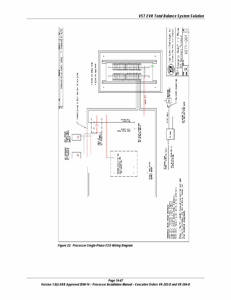
VST EVR Total Balance System Solution
Page 14-67 Version 1.0(i) ARB Approved IOM-14 – Processor Installation Manual – Executive Orders VR-203-D and VR-204-D
Figure 22: Processor Single-Phase ESO Wiring Diagram
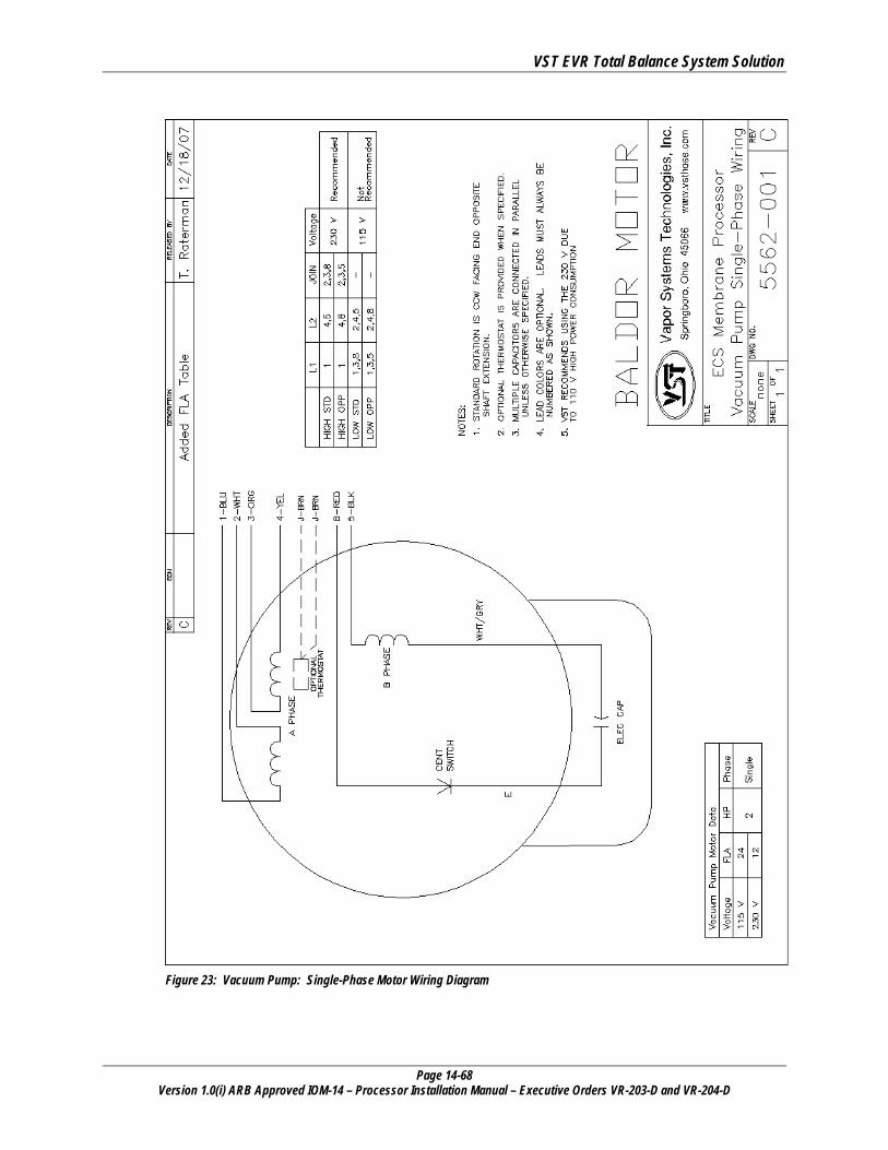
VST EVR Total Balance System Solution
Page 14-68 Version 1.0(i) ARB Approved IOM-14 – Processor Installation Manual – Executive Orders VR-203-D and VR-204-D
Figure 23: Vacuum Pump: Single-Phase Motor Wiring Diagram
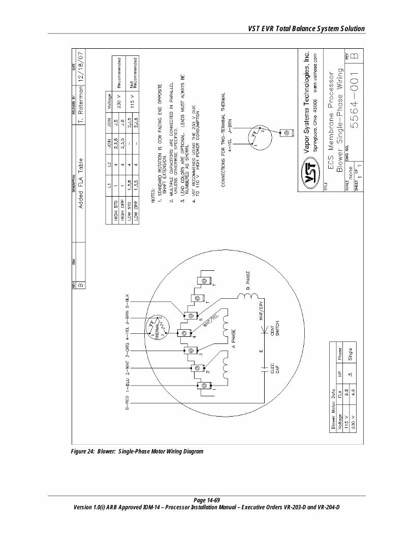
VST EVR Total Balance System Solution
Page 14-69 Version 1.0(i) ARB Approved IOM-14 – Processor Installation Manual – Executive Orders VR-203-D and VR-204-D
Figure 24: Blower: Single-Phase Motor Wiring Diagram
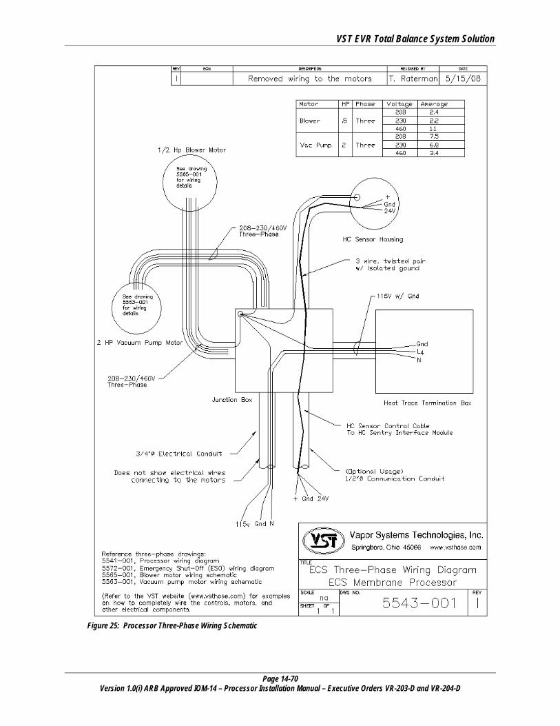
VST EVR Total Balance System Solution
Page 14-70 Version 1.0(i) ARB Approved IOM-14 – Processor Installation Manual – Executive Orders VR-203-D and VR-204-D
Figure 25: Processor Three-Phase Wiring Schematic
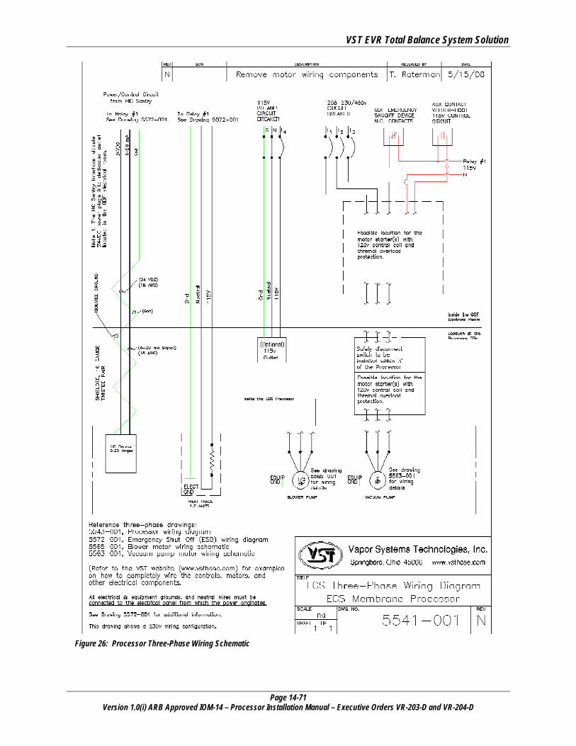
VST EVR Total Balance System Solution
Page 14-71 Version 1.0(i) ARB Approved IOM-14 – Processor Installation Manual – Executive Orders VR-203-D and VR-204-D
Figure 26: Processor Three-Phase Wiring Schematic
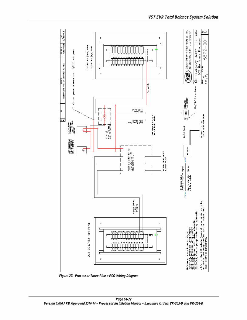
VST EVR Total Balance System Solution
Page 14-72 Version 1.0(i) ARB Approved IOM-14 – Processor Installation Manual – Executive Orders VR-203-D and VR-204-D
Figure 27: Processor Three-Phase ESO Wiring Diagram
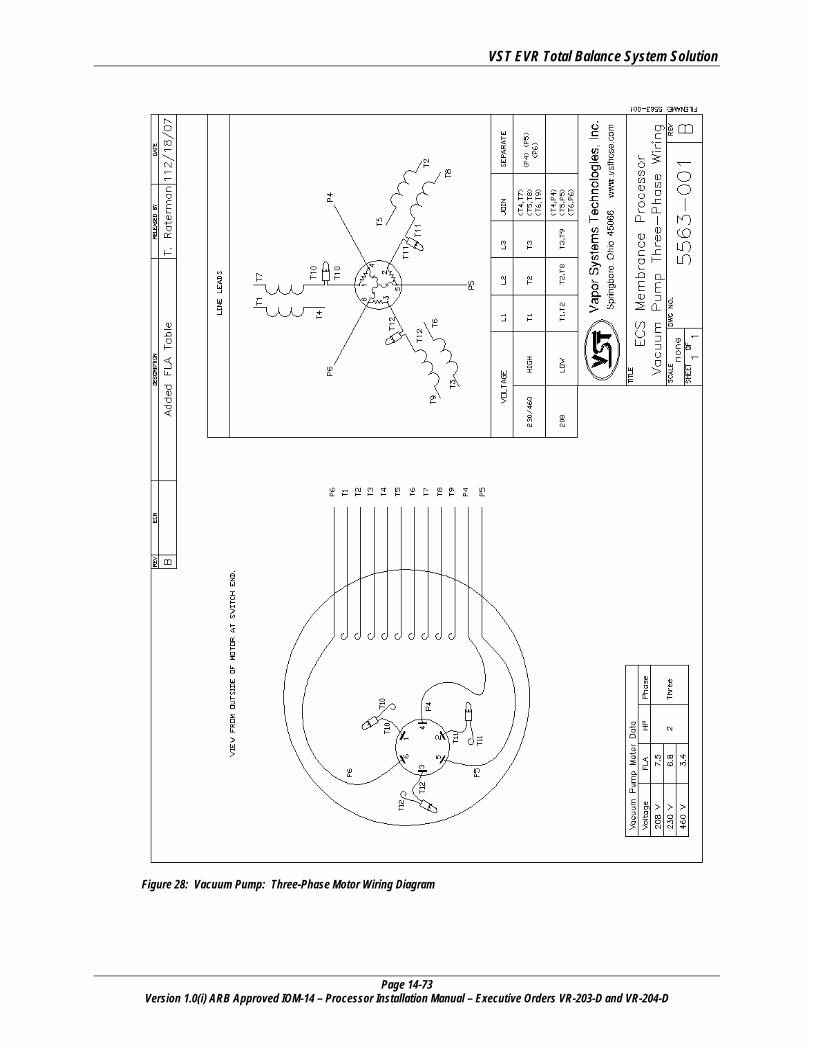
VST EVR Total Balance System Solution
Page 14-73 Version 1.0(i) ARB Approved IOM-14 – Processor Installation Manual – Executive Orders VR-203-D and VR-204-D
Figure 28: Vacuum Pump: Three-Phase Motor Wiring Diagram
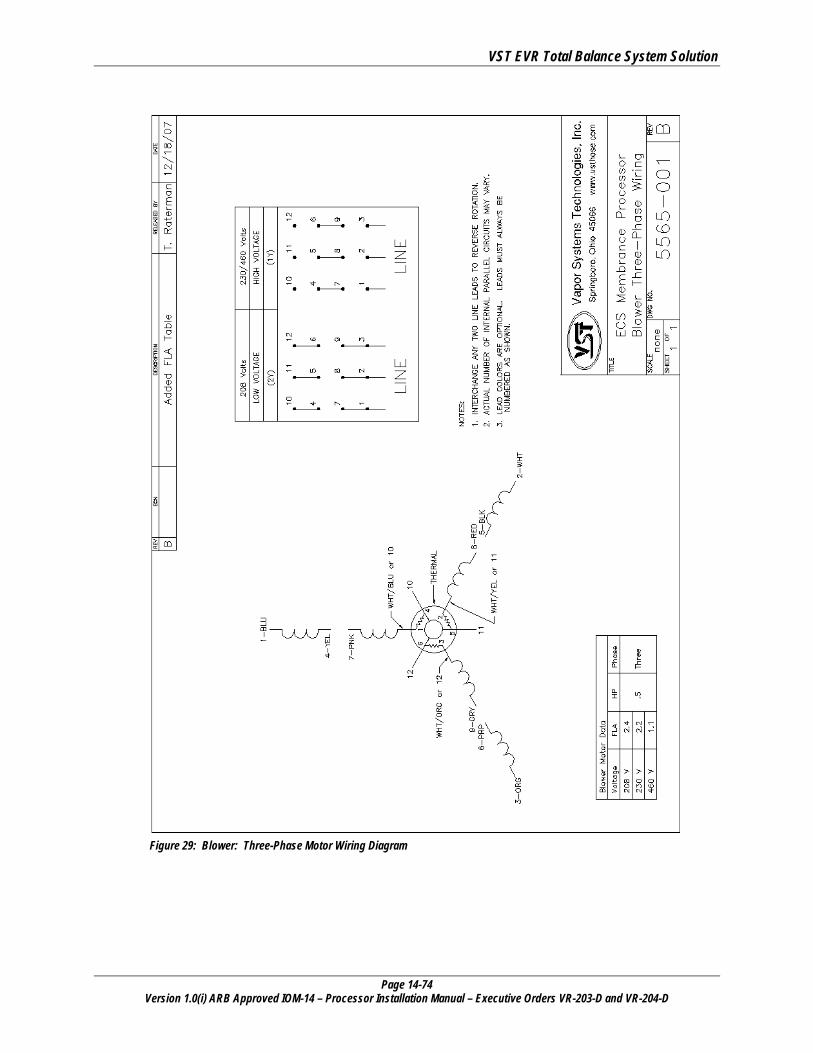
VST EVR Total Balance System Solution
Page 14-74 Version 1.0(i) ARB Approved IOM-14 – Processor Installation Manual – Executive Orders VR-203-D and VR-204-D
Figure 29: Blower: Three-Phase Motor Wiring Diagram
VST EVR Total Balance System Solution
Page 14-75 Version 1.0(i) ARB Approved IOM-14 – Processor Installation Manual – Executive Orders VR-203-D and VR-204-D
13.4 Auxiliary Output Relay • Run two wires from motor relay contacts to the Veeder-Root TLS.
DO NOT MAKE THIS FINAL CONNECTION. THIS FINAL CONNECTION IS TO BE MADE AT THE TIME OF START-UP. THIS ACTION REQUIRES THAT THE VST ASC (LEVEL C) BE A VEEDER-ROOT CERTIFIED CONTRACTOR WITH A MINIMUM OF VEEDER-ROOT LEVEL 1, OR 2/3, OR 4 CERTIFICATION.
► The user interface is equipped with an Auxiliary Output Relay for external monitoring of the Processor.
• The 115V control voltage for the motor control contactor is from the 115V electrical panel.
• This relay will be used when the Processor is installed with a PMC or an ISD system as specified by CARB Enhanced Vapor Recovery Program.
• When the Processor is powered and operating normally, the auxiliary relay is energized (green LED on Auxiliary Relay is lit).
• In ISD, when the Processor is powered off (either manually or due to an alarm mode), or is in alarm mode, the auxiliary relay is de-energized.
• Auxiliary relay contact rating: 240V, 6A with 4000V isolation. ► Connect the Processor motor control relay on either the 4-Relay Module or
the I/O Combination Module.
► DO NOT CONNECT TO POWER
► See Figure 30: Page 14-76.
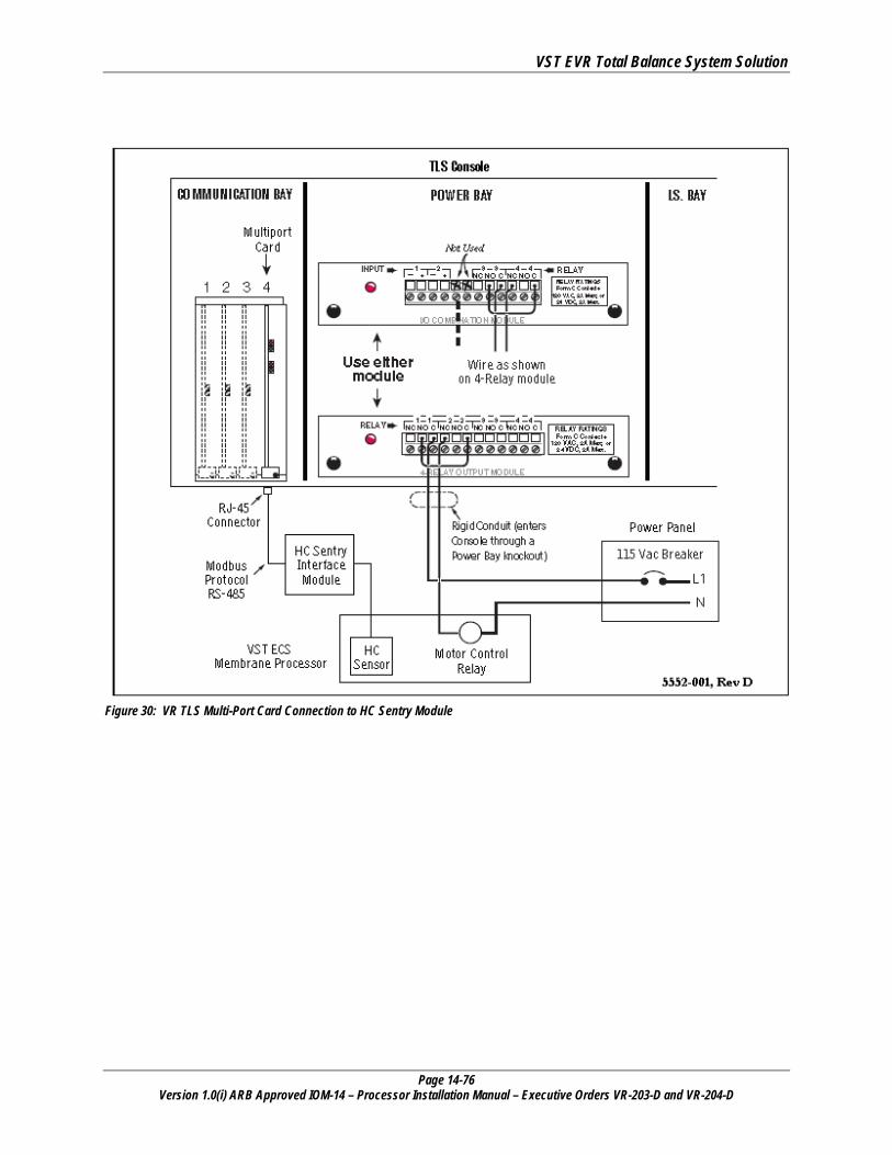
VST EVR Total Balance System Solution
Page 14-76 Version 1.0(i) ARB Approved IOM-14 – Processor Installation Manual – Executive Orders VR-203-D and VR-204-D
Figure 30: VR TLS Multi-Port Card Connection to HC Sentry Module
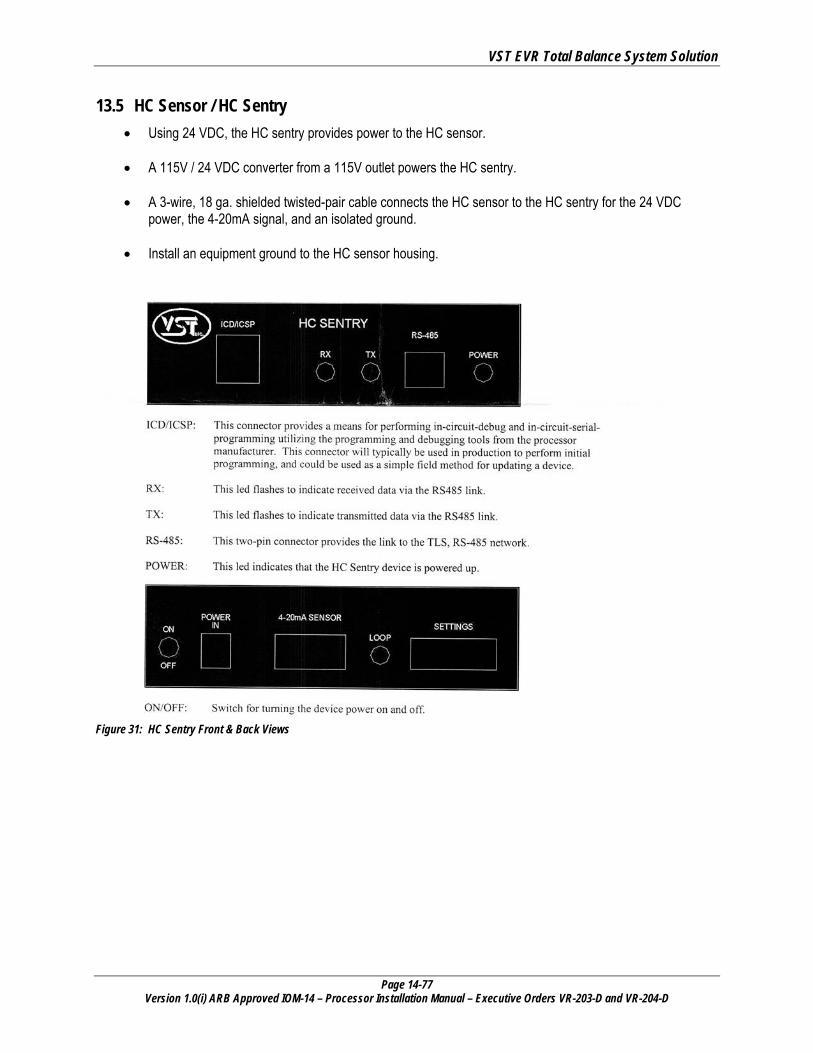
VST EVR Total Balance System Solution
Page 14-77 Version 1.0(i) ARB Approved IOM-14 – Processor Installation Manual – Executive Orders VR-203-D and VR-204-D
13.5 HC Sensor / HC Sentry • Using 24 VDC, the HC sentry provides power to the HC sensor.
• A 115V / 24 VDC converter from a 115V outlet powers the HC sentry.
• A 3-wire, 18 ga. shielded twisted-pair cable connects the HC sensor to the HC sentry for the 24 VDC
power, the 4-20mA signal, and an isolated ground.
• Install an equipment ground to the HC sensor housing.
Figure 31: HC Sentry Front & Back Views
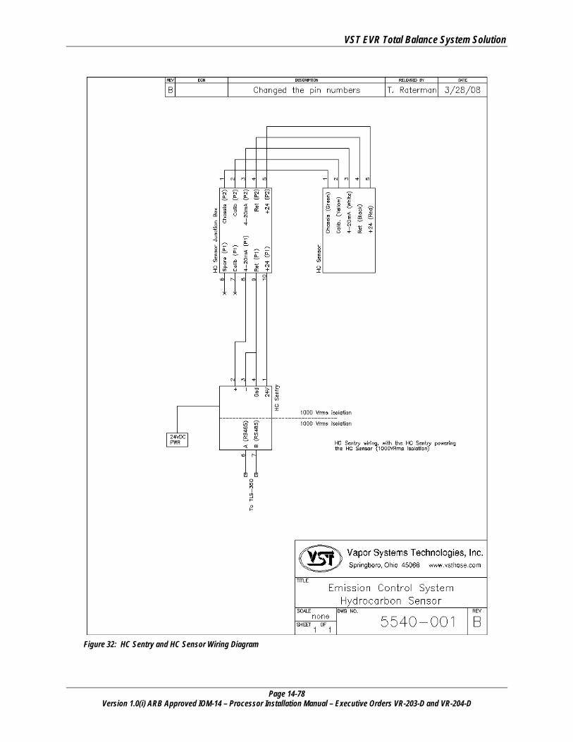
VST EVR Total Balance System Solution
Page 14-78 Version 1.0(i) ARB Approved IOM-14 – Processor Installation Manual – Executive Orders VR-203-D and VR-204-D
Figure 32: HC Sentry and HC Sensor Wiring Diagram

VST EVR Total Balance System Solution
Page 14-79 Version 1.0(i) ARB Approved IOM-14 – Processor Installation Manual – Executive Orders VR-203-D and VR-204-D
Figure 33: HC Sensor and HC Sentry Pictures

VST EVR Total Balance System Solution
Page 14-80 Version 1.0(i) ARB Approved IOM-14 – Processor Installation Manual – Executive Orders VR-203-D and VR-204-D
13.6 Multiport Card for Vapor Processor Communication • Run wire from HC sentry to TLS
► This action requires that the VST ASC (Level B) be a Veeder-Root Certified Contractor with Level 1, or 2/3, or 4
certification.
• The HC sensor is powered by the HC Sentry Interface Module using 24VDC power.
• Power required for the HC Sentry Interface Module is 24VDC power supply plugged into an 115VAC outlet.
• A three-wire, 18-gauge, shielded twisted-pair cable connects the HC sensor to the HC Sentry Interface Module for the 24VDC power, the 4-20mA signal, and an isolated ground.
• The wiring from the HC sensor is connected to the two twisted pair wires inside the HC electrical housing.
• See Figure 34: Page 14-80 - TLS / HC Sentry RS-485 Cable for the wiring diagram. ► VST provides the HC Sentry Interface Cable.
Figure 34: VR TLS Multi-Port Card Connection to the HC Sentry Module

VST EVR Total Balance System Solution
Page 14-81 Version 1.0(i) ARB Approved IOM-14 – Processor Installation Manual – Executive Orders VR-203-D and VR-204-D
Figure 35: HC Sentry RS-485 Cable Wiring Diagram
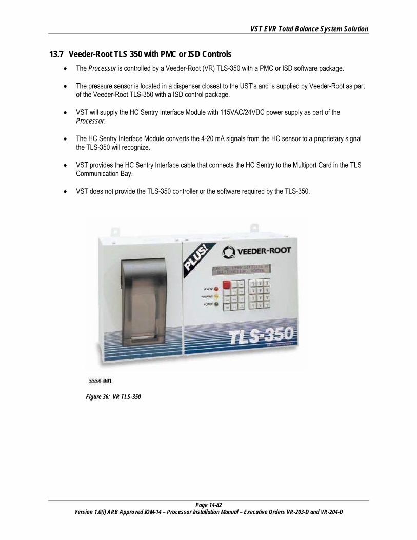
VST EVR Total Balance System Solution
Page 14-82 Version 1.0(i) ARB Approved IOM-14 – Processor Installation Manual – Executive Orders VR-203-D and VR-204-D
13.7 Veeder-Root TLS 350 with PMC or ISD Controls • The Processor is controlled by a Veeder-Root (VR) TLS-350 with a PMC or ISD software package.
• The pressure sensor is located in a dispenser closest to the UST’s and is supplied by Veeder-Root as part
of the Veeder-Root TLS-350 with a ISD control package.
• VST will supply the HC Sentry Interface Module with 115VAC/24VDC power supply as part of the Processor.
• The HC Sentry Interface Module converts the 4-20 mA signals from the HC sensor to a proprietary signal the TLS-350 will recognize.
• VST provides the HC Sentry Interface cable that connects the HC Sentry to the Multiport Card in the TLS Communication Bay.
• VST does not provide the TLS-350 controller or the software required by the TLS-350.
Figure 36: VR TLS-350
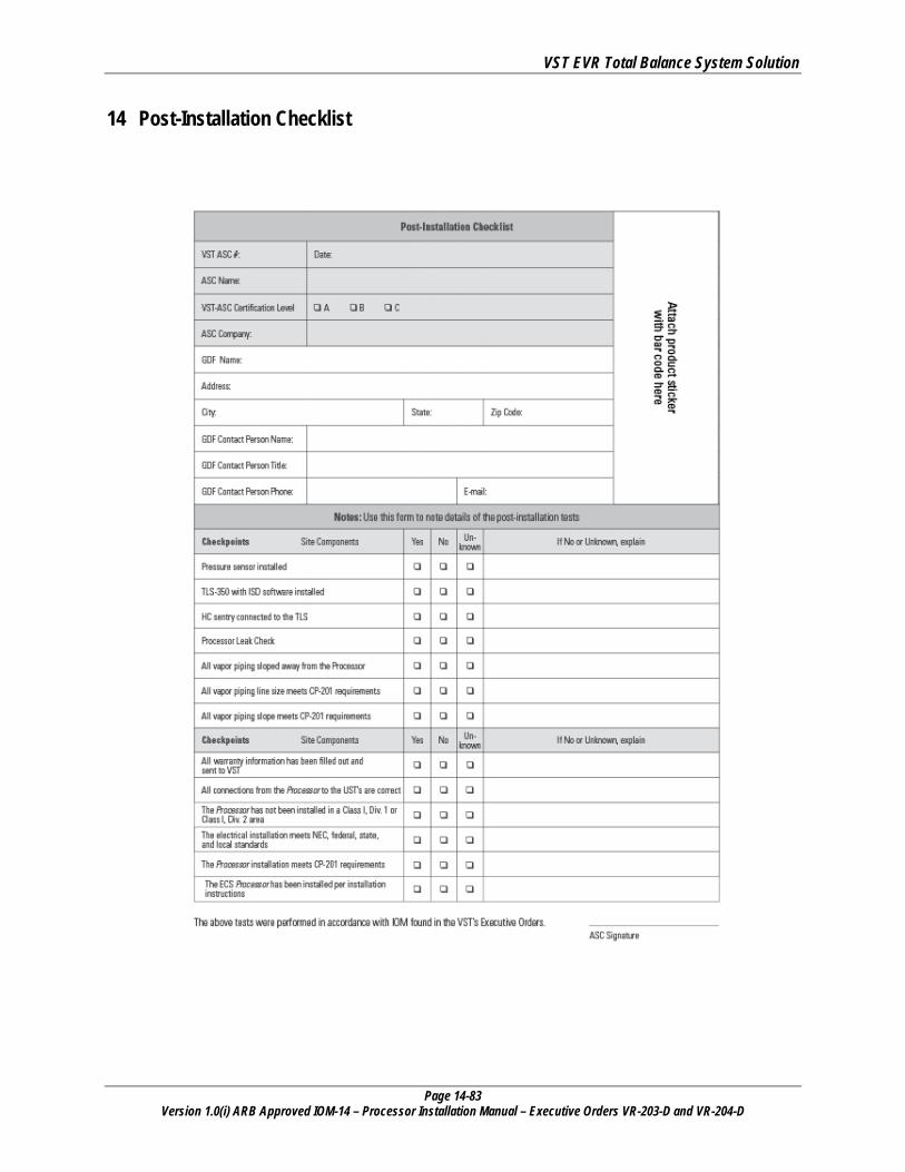
VST EVR Total Balance System Solution
Page 14-83 Version 1.0(i) ARB Approved IOM-14 – Processor Installation Manual – Executive Orders VR-203-D and VR-204-D
14 Post-Installation Checklist