Embed Size (px)
Citation preview

EO:6918 Rev 10
1-2013 80122701
Installation Manual
HLF-25, 30, 40, & 50 2500, 3000, 4000, & 5000 lb. Capacity Flipaway Liftgates
Last Change
Date Page(s) Description
1-2013 33 & 35 P33, Added schematic decal to pump cover, P35, Added removal of shims
to final checklist
Waltco Lift Corp. Waltco Lift Corp. Waltco Lift Inc. Corporate Office United State United States Canada 285 Northeast Ave. 620 S Hambledon Ave. 90 North Queen St. Tallmadge, OH 44278 City of Industry, CA 91744 Etobicoke, ON M8Z 2C5 P: 330.633.9191 P: 626.964.0990 P: 888.343.4550 F: 330.633.1418 F: 626.964.0149
www.waltco.com Phone: 800.411.5685 [email protected] Fax: 800.411.5684

Table of Contents
Introduction ................................
Safety Information ................................
Liftgate Terminology ................................
Basic Mounting Requirements
Installation ................................
Placement of Decals ................................
Lubrication Instructions ................................
Final Inspection ................................
How to Order Parts ................................
Optional Kit Instructions:
Hand Held Remote Kit ................................Kit #80000430
Aux Dual Cable Battery Kit (Truck)Kit #80001066
Dual Cable Kit (Trailer) ................................Kit #80001069
Dual Control Kit ................................Kit #80000437
Cab Shut-Off Kit ................................Kit #80000827
Underride Kit ................................Kit #22796001 & 22796002
Walk Ramp Kit ................................Kits #22766001 & 22766002
Chain Anchor Kit ................................Kit #22745001
Improper installation of thideath.
Read and understand the contents of these instructions before proceeding. When installed, this liftgate must not alter or prevent vehicle compliance to any existing state or federal standards.
Each chassis manufacturer’s recommendations should be consulted for compliance.
Table of Contents
................................................................................................
................................................................................................
................................................................................................
Basic Mounting Requirements ........................................................................................
.......................................................................................................................
................................................................................................
................................................................................................
................................................................................................
................................................................................................
................................................................................................
Battery Kit (Truck) ................................................................
................................................................................................
................................................................................................
................................................................................................
................................................................................................
................................................................................................
................................................................................................
Improper installation of this liftgate could result in severe personal injury or
Read and understand the contents of these instructions before proceeding.
When installed, this liftgate must not alter or prevent vehicle compliance to any existing state or federal standards.
Each chassis manufacturer’s recommendations should be consulted for
..................................................... 3
........................................... 4
....................................... 6
........................ 9
....................... 10
....................................... 32
................................... 34
............................................... 35
......................................... 51
.................................... 35
................................................. 38
................................... 39
............................................... 43
.............................................. 44
................................................... 45
................................................ 46
............................................. 49
s liftgate could result in severe personal injury or
Read and understand the contents of these instructions before proceeding.
When installed, this liftgate must not alter or prevent vehicle compliance to any
Each chassis manufacturer’s recommendations should be consulted for
Page 2

Introduction If anyone observes improper installation, improper operation, or damage, they should immediately
contact a qualified person for assistance and correction. We strongly urge anyone that has any questions or doubts as to the installation, condition, use, operation, maintenance or repair of the liftgate to contact us at Waltco where we have qualified personnel that will be happy to assist you. Telephone numbers and addresses of these locations are listed in the Owner’s Manual and Installation Instructions. INSTALLATION
Waltco liftgates should only be installed by those with sufficient basic skills to understand the installation and operation of the liftgate, along with the equipment on which the liftgate is being installed. Waltco’s installation instructions are not intended to give rationale for all the instructions that are given; however, it is the intent of these instructions to give the installer both the operations and what we believe to be the most desirable sequence of implementing these operations. These instructions can in no way expand into an area where they will replace a qualified person, or clear thinking and a basic knowledge that must be possessed by the installer.
It has been our experience that a knowledgeable journeyman following these instructions and observing the operation of the liftgate will have a sufficient comprehension of the liftgate to enable this person to troubleshoot and correct all normal problems that may be encountered.
Failure to follow the installation instructions, adjustments and mounting dimensions may result in improper and unsafe operation of the liftgate. Unauthorized alterations of the liftgate can cause an undesirable and dangerous condition. OWNER’S MANUAL
The Waltco Owner’s Manual is intended to act as a guide for operation and routine maintenance but is no way intended to encourage usage or repair of the liftgate by those who are not qualified to do so.
The contents of the owner’s manual include, but are not limited to general operation instructions, routine lubrication, parts lists, and an outline of things that should be checked but may not be obvious to those not technically qualified. This manual assumes the liftgate is properly installed, undamaged and operates correctly. Improper installation, improper operation, or damage should be immediately corrected by a qualified person. INSPECTION
As part of the regular inspection of a liftgate and after damage or suspicion of an overload, inspect for wear or structural damage and make necessary repairs or replacements. Check all structural components and their attachment to the liftgate for cracked welds, loose fasteners, wear and part deformation. Check cylinder and hose for leaks. Inspections and repairs should be made by a qualified mechanic. REPLACEMENT PARTS
Use only Waltco original equipment replacement parts. Components of other liftgate manufacturers may outwardly appear to be the same but are not interchangeable with Waltco products. Waltco components are specifically designed for safety requirements, reliability and compatibility with our products. Refer to your Waltco parts manual when ordering parts. NOTE: When ordering, give model and serial number of liftgate. DECALS
It is important that every vehicle that has a WALTCO Liftgate have legible DECALS clearly posted on the vehicle and an OWNER’S MANUAL in the vehicle at all times as a guide for proper operation and maintenance. Additional DECALS and OWNER’S MANUALS can be obtained from WALTCO LIFT CORP.
Page 3

Chapter 1 Safety Information
WARNING
Read, understand, and follow all of the warning listed below.
Failure to follow these warning could result in severe personal injury or death.
• Read and understand the Owner’s Manual, all decals and warning on liftgate before operating liftgate.
• Do not operate liftgate without a thorough knowledge and understanding of the operation of the liftgate.
• Liftgate hazards can result in crushing or falling.
• This liftgate is designed for loading and unloading of cargo. If personnel are required to ride liftgate, observe and familiarize yourself with the liftgate operation, decals and manuals. Ensure stable footing at all times.
• Do not ride liftgate with unstable loads.
• Wheeled loads must be properly retained from rolling.
• Tall, high center of gravity loads must be retained from falling over.
• Never overload liftgate:
Load platform as close to the vehicle, and towards the middle of the platform as possible. Refer to owner’s manual and capacity decal of liftgate for maximum load and load placement.
• Keep hands and feet clear of all potential pinch points.
• Never use liftgate if it makes any unusual noise, has unusual vibration, raises or lowers unevenly, or fails to operate smoothly.
• Never use liftgate if it shows any signs of structural damage such as cracked welds, bent or distorted members.
• Do not attempt any repairs unless you are qualified to do so. Care should be taken when work is performed on a disabled liftgate located near moving traffic. When possible the vehicle should be moved away from traffic areas for repair. Precautionary measures should be taken to ensure personal safety including those recommended in Federal Motor Vehicle Safety Standards 571.125.
• When welding to liftgate, or liftgate components, take all necessary safety precautions, including using respiratory protection and other pertinent personal protective gear when welding harmful materials.
• All protective covers, guards, and safety devices must be in place and access doors closed before operating liftgate.
• Do not allow anyone to stand in, or near area, in which Platform will open and close before opening or closing Platform.
• Do not allow anyone to stand near the Platform where a falling load could land on them.
• Platform is always to be properly stored and secured for transit. See the Owner’s Manual for details.
• Take care to retain cargo during transit for liftgate Platforms which function as the tailgate or door of the cargo area. Small objects can fall through the space between the vehicle and the folded Platform.
• A Lock-Out device or Shut-Off Switch should always be used to prevent unauthorized use of liftgate.
• For liftgates with Runners, never use liftgate if Runners do not travel freely and smoothly.
• For liftgates with Roller Lifting Chain, the Chain should be replaced every (5) five years or 15,000 cycles, whichever comes first. Replace only with Waltco approved Roller Chain.
• Never transfer loads which exceed lifting capacity on or over any part of the Platform unless the liftgate is equipped with a special reinforced Platform and Platform Support Bars for use when the Platform is used as loading ramp (dock board). Refer to the “Using Platform as a loading ramp” Chapter in the Operation Instructions of the BZ/RZ series Owner’s Manual.
• For liftgates equipped with Trailer Hitches, never exceed the rated capacity of the hitch. Do not exceed the vehicle’s weight rating. Refer to the vehicle’s Owner’s Manual.
• Vehicle must comply with all state and federal standards.
• Follow the “Maintenance Guide” chapter in the Owner’s Manual.
Page 4

Liftgates with Tilt Function
• Proper use of the Control Switches is of extreme importance.
• Improper use of Tilt Switch could cause load to fall from the Platform or damage the liftgate.
• Platform should be in a generally horizontal position when raising or lowering with a load.
• In any tilt position, the Platform may vary from level while raising or lowering the Platform.
Liftgates equipped with spring operated Cam Closer
• Replace Cam Release Spring every five (5) years or 15,000 cycles, whichever comes first.
RGL-Series Liftgates
• Make certain Platform Brake mechanisms are operating properly.
• The Runners are always to remain powered up against the Up-stops Pins when in transit.
• Inspect Cables every three (3) months or 750 cycles, whichever comes first. Cables must be replaced if they show signs of wear, distortion, kinking or if any broken wires are visible
• Replace cables every five (5) years or 10,000 cycles, whichever comes first.
This is the safety alert symbol. This manual uses this symbol to alert you to potential personal injury hazards. Obey all safety messages that follow this symbol to avoid personal injury or death.
SIGNAL WORDS
WARNING
Indicates a potentially hazardous situation, which if not avoided, could result in death or serious injury. Black letters on an orange background
CAUTION
Indicates a potentially hazardous situation, which if not avoided, may result in minor or moderate injury. May also be used to alert against unsafe practices. Black letters on a yellow background. NOTICE
Indicates a potentially hazardous situation, which if not avoided, may result in property damage.
WARNING
CAUTION
NOTICE
Page 5

Chapter 2 Liftgate Terminology 1. Hydraulic Cylinder 2. Hose Assembly 3. Hose Guard 4. Dual Hose Clamp 5. Pump Unit Starter Solenoid 6. Breather Cap 7. Lowering Valve Coil 8. Raise Valve Coil 9. Bulkhead Elbow, 90 Deg.
10. 90 Deg. Hose Fitting 11. Tee, Hose Fitting 12. Drain Plug 13. Pump 14. Thermal Switch (Inside Motor) 15. Ground Cable 16. Pump Unit Motor 17. Pump Unit Reservoir 18. Lock Valve
GR02778
2
7
6
8
14
5
1
10
4
3
16
13
12
15
1
2
4
9
11
17
2
9
18
Page 6

Chapter 2 Liftgate Terminology
19. Mount Tube Assembly
20. Parting Bar Assembly
21. Deck Assembly
22. Torsion Bar
23. Deck Extension Assembly
24. Lift Arm Assembly
25. Folding Assist Springs
26. Parallel Arm
27. Pump Box
28. Mount Plate
29. Spec Tag
30. Bed Extension
31. Dock Bumper
32. Transit Chain
GR02779
20
25
21
22
26
27
28
19
29
31
2324
30
32
Page 7
Chapter 2 Liftgate Terminology
Explanation of Specification Tag
Model Name Description Capacity
HLF Twin Cylinder 2500 lb.
HLF Twin Cylinder 3000 lb.
HLF Twin Cylinder 4000 lb.
HLF Twin Cylinder 5000 lb.
GR00241
GR02837
MODEL NAME RATED CAPACITY Based on an evenly distributed load on the platform flat surface.
SERIAL NUMBER of liftgate. To be used when ordering parts or when contacting Waltco for service or warranty questions
DATE OF MANUFACTURE Month / Year
Specification Tag
Page 8

Chapter 3 Determine Basic Mounting Requirements
Measure distance from ground to floor level. This is the bed height.
Refer to bed height dimension on mounting chart to determine basic mounting dimension “A” and minimum mount frame clearance required.
NOTE: Max bed height dimensions for unloaded vehicle. Min bed height dimensions for fully loaded vehicle
NOTE: Tire clearance should be 6” minimum between tire and mount frame.
GR00139
STANDARD BED HEIGHT MODELS
MOUNTING CHART
Bed Height “A” Dimension Mount Frame Clearance
46”-57” 25-1/2” 35-1/2”
57”-60” 26-1/2” 34-1/4”
GR02781
Bed Height (Ground to Floor)
395
8413
4
813
8
A - DIM
MOUNT FRAME
CLEARENCE
17
7
8
CENTER LINE
OF LIFTGATE
12
Page 9

Chapter 4 Installation
PREPARATION OF BODY SILL
Remove all obstructions that would interfere with operation of Liftgate; such as dock bumpers, trailer hitches, projections, etc.
Locate and mark the center of body sill.
NOTE:
All mounting measurements for centering liftgate will come from centerline mark.
Body sill must have clearances indicated. Cut or notch Rear Sill to obtain these clearances.
Refer to chart p. 3-1
Hold “X” as follows:
“A” Dimension “X” Max.
25-1/2” 6”
26-1/2” 7”
GR02184
Additional Notching.
Additional notching of the rear sill may be necessary on units with larger sills.
GR02782
46” TO 57” BED HEIGHT
25-1/2”
“A” Dimension
GR02783
“X”
Platform Width +2”
Cut away vehicle frame as required to obtain the minimum clearance indicated.
Page 10

Chapter 4 Installation
57” TO 60” BED HEIGHT
26-1/2”
“A” Dimensions
GR02784
Cap Vehicle Frame, using a 3/16” or 1/4” X 2” steel strap. Body Crossmember
3/16” or 1/4” x 2”steel strap
Vehicle Frame
GR00625
INSTALLATION OF BED EXTENSION If bed extension is to be bolted on, use pattern at right for drilling holes. Thirteen (13) 9/16” diameter holes required.
GR02905
Cut away vehicle frame as required to obtain the minimum clearance indicated.
Page 11

Chapter 4 Installation
Position Bed Extension up to rear sill using a forklift or crane. Make certain bed extension is centered on vehicle body and level with bed
Other means may be used to support Bed Extension in position. ALWAYS verify the safety of your supporting method before proceeding.
GR02647
IF BOLTING: Bed extension to sill, use thirteen (13) 1/2” bolts, nuts and washers provided with kit. Torque bolts to 90 ft. lbs. IF WELDING:
NOTE:
To help protect vehicle paint, notches have been provided so top of bed extension does not have to be welded.
NOTE:
If corner posts of vehicle body extend beyond rear sill of body, shims may be added behind bed extension to prevent bowing of bed extension.
Weld underside of Bed Extension.
Weld all Notches 100% with 1/8” weld to rear sill of vehicle body.
Weld under the side bars and all gussets with 1/8” weld x 2” long.
GR02648
Bottom of Side Bar
Notches
Bottom of Gussets
Bed Extension
Page 12

Chapter 4 Installation
ALTERNATIVE WELDING OF BED EXTENSION Weld top side of bed extension, 1/8” x 2” welds over each of the notches on underside of extension.
Weld under the side bars and all gussets with 1/8” weld x 2” long.
GR02647 & 48
Remove liftgate from shipping pallet, and all banding. Do not unfold platform until instructed to do so.
STOP Before proceeding; verify vehicle bed
height and A-dimension to be used! Refer to Chapter 3 of this manual. NOTE: If mounting to 26-1/2” A-Dimension, the Mounting Bars will need to be removed before proceeding. Do not remove the Auto Tilt Wedge Blocks. Mount Bars are set for 25-1/2” A-Dimension when shipped from factory. Do not remove Mounting Bars until instructed to do so. Unfold platform to open position.
GR02785
Mounting Bar
(Each Side)
Auto Tilt Wedge
Block (Each Side)
Under Gussets
Under Side Bars
1/8” weld x 2” long above each of the notches
Page 13

Chapter 4 Installation
Bed Extension
Centerline of body, bed
extension and platform
A-Dim
Bed Extension
Platform
3/16” Shim
Platform
3/16” Coil Pin for
shims
2 places
Position liftgate up under vehicle. Using a forklift or crane, raise platform up to bed extension.
Ensure 3/16” coil pins are between platform and bed extension skins.
Platform to be centered on vehicle, and level with floor (bed) of vehicle.
A jack can be used to help position mount tube to proper A-Dimension.
Be sure platform is centered on vehicle body and bed extension.
Other means may be used to support Liftgate in position. ALWAYS verify the safety of your supporting method before proceeding.
Position platform so it is level with vehicle body, and verify proper A-Dimension. NOTE: If unable to obtain correct A-Dimension with platform level, it may be necessary to screw in the Platform Adjustment Bolts as shown below. Platform and Mount Tube should be level.
GR02786 & GR02787 & GR02937
Page 14

Chapter 4 Installation
Bolts heads should be contacting platform hinges, if they are not, ensure the platform and mount tube are parallel prior to adjusting.
Note: Platform springs are engaged and under tension.
Take care when adjusting liftgate.
GR02660
Use two 3” channels (tubes, or similar), lay on vehicle floor and clamp to bed extension and platform as shown.
Install counter weight on channels as required.
Platform is to be held parallel with vehicle floor, and is to shimmed 3/16” away from bed extension, centered with vehicle body.
Other means may be used to support Liftgate in position. ALWAYS verify the safety of your supporting method before proceeding.
IMPORTANT: Verify mount tube is at correct A-Dimension before proceeding to next step:
• Correct A-Dimension for bed height
• If using 26-1/2” A-Dimension and no mounting bar, square up mount tube with ground by temporarily powering the gate to obtain the correct A-Dimension.
GR02788
CONFIRM PROPER MOUNT PLATE
Higher capacity liftgates (4000# & 5000#) must use 5/8”Mount Plate
Confirm the capacity and mount plate profiles match the picture to the right.
Contact Waltco immediately if you have a high capacity liftgate with the wrong mount plate.
GR02899
3/8" 5/8"
For 2500# & 3000#
(2 notches)
For 4000# & 5000#
(1 notch)
Channel
Counter
Weight
Platform Bed
Extension
3/16” Shims
Platform Adjustment Bolt
Page 15

Chapter 4 Installation
Non-Galvanized: 3/8” weld 100%, all around both sides and ends
5-1/4” Min.
Mount Tube
Mount Plate
FOR GALVANIZED, BOLT-ON MOUNT PLATES
Align mount plates with outside surface of brackets on mount tube. Loosely install all of the ¾” diameter hardware to hold mount plate in position.
Once aligned, weld mount plates to chasis frame per instructions below.
Tighten hardware after welding to 250-300 ft-lbs.
GR02907
MOUNT PLATE INSTALLATION
Locate mount plates on mount tube. Mount plates should be approximately 90° to vehicle frame.
Check that mount plates extend a minimum of 5-1/4" above bottom of vehicle frame. If dimension cannot be held, refer to the optional installation.
Shield all wires and hoses from heat and weld splatter.
Recheck “A” dimension. Weld three sides of mount plates 100% to vehicle frame with 3/8” weld.
For Non-Galvanized units: Weld mount tube to the mount plates. Weld all around, both sides of the mount plates, and ends, with 3/8" weld.
To avoid injury or property damage, do not remove clamps from deck. Use forklift, crane, or other safe means to support deck and then remove clamps.
GR02789
¾” dia hardware
Torque to 250 -
300 ft-lbs
Mount plate
to be on
outside of
brackets.
3/8” weld 100%, three sides of Mount Plates
Page 16

Chapter 4 Installation
3/8” weld 100%, three sides of mount plate and adapter plates as shown.
3/8” Adapter Plate
5-1/4” Min.
OPTIONAL INSTALLATION
If the 5-1/4” dimension cannot be met a 3/8” thick plate must be added.
Shield all wires and hoses from heat and weld splatter.
Recheck “A” dimension. Weld three sides of mount plates and three sides of 3/8” plate 100% with 3/8” weld.
For Non-Galvanized units: Weld mount tube to mount plates. Weld all around, both sides of mount plates, and ends, with 3/8" weld.
To avoid injury or property damage, do not remove clamps from deck. Use forklift, crane, or other safe means to support deck and then remove clamps.
GR02790
NOTE: If necessary, liftgate may be mounted to inside of frame as shown.
GR02791
37” or wider
One 8” to 12” channel or two 5” to 6” channels
Weld channel to Truck Frame with 3/8“ weld. Weld 100% all around as shown.
Weld Mount Plate to channel with 3/8” weld after channel is welded to the Truck Frame.
5-1/4” Min.
5-1/4” Min.
Non-Galvanized 3/8” weld 100%, all around both sides and ends of mount plates.
Truck Frame
Page 17

Chapter 4 Installation
INSTALLATION OF CONTROLS Locate switch such that, when operating liftgate, operator will have clear view of entire platform area and will not be in area that liftgate will pass through. Use this template to locate screw holes, and hole for control cord.
GR02662
If Control Cord will be run through a hole of body, remove all sharp edges from hole.
Use 1/4” Self-tapping Screws to secure switch.
GR02761
1/4-20 Self Tapping Screws
Corner Post
Control Cord
Page 18

Chapter 4 Installation
Route control cord into pump enclosure, using grommet supplied. Hints:
With grommet loose, insert largest terminal of control cord through the grommet first, then the others.
Apply a drop or two of oil on grommet to help insert terminals through grommet, and to install grommet into pump enclosure.
Connect control cord to pump unit as shown. Terminals are gendered to allow only correct connections.
Note: Some components not shown for clarity.
GR02765
INSTALLING BATTERY CABLES Route both power and ground cables into pump enclosure using grommets as shown. Note: The power cable has red ends, ground cable is all
black. Power cable is bolted to either one of the solenoids and copper bus bar. Ground cable is bolted to pump unit side, with Lock Valve ground wire. Route power and ground cables along truck chassis, towards truck batteries, securing them every 24” with cable ties provided.
Do not connect any cables to batteries at this time.
Be certain cables are protected with grommets when passing through metal holes or over sharp edges.
Note: Some components not shown for clarity.
GR02765
Power Cable (Red)
Lock Valve Wires
Solenoid
Ground Cable (Black)
Grommets
Pump Enclosure
Grommet Control Cord
Page 19

Chapter 4 Installation
INSTALLATION OF TERMINAL LUG
Strip 1” to 1-1/4” of insulation from end of cable.
Slide heat shrinkable tubing onto cable.
Insert bare wire into compression nut until it seats.
IMPORTANT: Be sure to use correct compression nut, use 1&2 gauge nut for 1 gauge cable, use 0 gauge nut for 0 gauge cable.
Note: Copper wire should be flush with, or slightly past nut
7/8” to 1”
Heat shrinkable tubingbefore installation
GR00299
Grip nut with wrench and turn terminal until nut seats
GR00300
Position heat shrinkable tubing over terminal and end of cable
Shrink tubing using electric heat gun or torch.
Note: To reduce chance of damaging tube and cable, a heat gun is recommended
Apply sufficient heat to produce thin bead of sealant all around tube edges
Heat ShrinkableTubing
Beads of Sealant
GR00301
Compression Nut
1” – 1-1/4”
Page 20

Chapter 4 Installation
INSTALLATION OF POWER CABLES
These instructions are for connecting to truck batteries only. Refer to auxiliary battery instructions in back of this manual.
Locate and mount circuit breaker directly to batteries using copper terminal link supplied.
Circuit breaker must be mounted to give good protection against any objects coming into contact with circuit breaker terminals and causing a short. Position must also be readily accessible to reset breaker.
NOTE: Circuit Breaker is to rest solidly on battery to prevent vibration during transit.
If unable to connect circuit breaker direct to batteries, an optional jumper cable can be made from excessive length of power cable, see instructions above for installing terminal lugs.
Connect power cable (positive) from liftgate to circuit breaker. Then connect ground cable to negative terminal on batteries.
Apply a generous amount of Dielectric Grease to all Battery terminals and Circuit Breaker terminals.
Protect wires from any sharp edges or holes that may abrade insulated covering of wires.
Secure battery cable so it does not come near, or in contact with, other vehicle wiring, fuel lines, brake lines, air hoses, exhaust system, etc.
IMPORTANT: DO NOT operate liftgate until Mounting Bar has been removed.
GR02764
Vehicle Batteries
Circuit Breaker
Battery Cables from Liftgate
Copper Terminal Link
Page 21

Chapter 4 Installation
Electrical Schematic
GR02798
DIVERT WATER FROM ENCLOSURE
To help prevent channeling water into pump or battery enclosures:
• Secure hoses, cables and cords downward as they exit the enclosure.
• If a downward exit is impractical, a Zip Tie can be installed around hose or cable to help interrupt the flow of water as shown.
GR02460
HOSE INSTALLATION
Avoid twisting of hoses. Avoid sharp bends when routing hoses Hoses will contract under pressure. Allow plenty of slack between connecting points. Do not clamp hoses at bends to allow for length changes when hose is pressurized.
No Pressure
High Pressure
GR00717
Zip Tie
Pump or Battery Enclosure
Flow of water
Page 22

Chapter 4 Installation
REMOVE MOUNTING BAR, WEDGE BLOCKS, AND 3/16” COIL PIN SHIMS
Insure platform is properly supported before disconnecting the Mounting Bars and Wedge Blocks.
Do not be under platform or lift arms when disconnecting the Mounting Bar. Access bar from forward side of mount tube.
Remove two 3/16” coil pins from platform at spring retainer.
GR02785
FILLING HYDRAULIC RESERVOIR
Position liftgate deck into raise position (use forklift,
crane, or other safe device if necessary).
Remove Reservoir Plug.
Oil level should be 1/2” from top of reservoir in raised position.
If low, fill as required.
Replace Plug with Breather.
Run liftgate full cycle several times to release trapped air from system.
GR02792
Mounting Bar
(Each Side)
Auto Tilt Wedge
Block (Each Side)
Coil Pins
Replace cap
with Breather
Page 23

Chapter 4 Installation
Lock Valve
Lowering
Solenoid
Valve
Raise
Solenoid
Valve
Hydraulic Schematic
GR02797
Recommended Fluids Fill reservoir
Temperature Range Acceptable Fluids • Fill with recommended fluid or equivalent.
0° to 120° F Waltco Biodegradable Liftlube
TM part #85803860
• Fill the reservoir to within 1/2” from the top.
• Fluids are available from the Waltco parts Shell Tellus S2 V 32 Dept. 1-800-411-5685 www.waltco.com
Chevron AW32
-20° to 90° F Waltco Biodegradable
LiftLube Arctic part #85803866
NOTE: Do not use the following fluids:
Shell Tellus S2 V 15 Mobil DTE 13 MIL – H - 5606
Brake Fluid
Power steering fluid
Automatic Transmission Fluid (ATF)
A good quality SAE 10W motor oil may also be used in
temperatures above 32° F.
Page 24

Chapter 4 Installation
There is no speed adjustment on this liftgate.
Lowering speed is controlled by the pressure compensative valve plumbed into the pump.
Regardless of weight on platform, liftgate should lower at approximately six (6) inches per second.
Bed Height (inches) = Lowering Time (seconds)
6
This liftgate must have the pressure compensative valve installed in the pump.
GR02792
ADJUSTMENT OF PARTING BAR
IMPORTANT: Parting bar and rubber snubbers MUST be installed before attempting to fold platform and raise to stored position.
The snubbers are necessary to protect platform from contacting the chassis frame and damaging paint on platform.
NOTE: Identify parting bar supplied and proceed to proper instructions.
PARTING BAR 1:
To assist the opening of the platform:
If vehicle is 52” or less without walk ramp, proceed to next page of instructions.
Hole 1 (As shipped): For vehicles with no walk ramp. Hole 2: For vehicles with walk ramp or vehicle bed height exceeds 57”.
Platform is to lean in towards parting bar when at ground. It is not to fall open to ground.
GR02799
Hole 1 Hole 2
2 to 18 degree lean
Parting Bar
¼” 100% weld
after located
PARTING BAR 1 – This Page
PARTING BAR 2 – Next Page
Pressure Compensative Flow Control Valve inside Pump
Page 25

Chapter 4 Installation
Roller Bracket Adjustment: (For bed heights above 52” and all walk ramp applications)
Verify roller bracket is in correct orientation for bed height of vehicle and walk ramp application.
If needed, remove all (3) three bolts to re-orientate the roller bracket as show for correct application.
NOTE: Platform must lean towards parting bar between 2 and 18
degrees.
IMPORTANT: Improper installation of parting bar can result in damage to the liftgate platform, by powering into the chassis frame of vehicle. WELD PARTING BAR AFTER FUNCTIONALITY IS CONFIRMED. ¼” WELD 100% GR02800
PARTING BAR 2:
To assist the opening of the platform:
Vehicles without walk ramp: Lower platform to ground with slight tilt towards vehicle as shown. Slide parting bar to platform and bolt into place. Vehicles with walk ramp: Locate parting bar in hole closest to mount tube and bolt into place. Tighten nuts and bolts to 50 ft lbs.
Platform is to lean in towards parting bar when at ground. It is not to fall open to ground.
GR02900
Walk Ramp Position
2 to 18 degree lean
Parting Bar
23"
2534"
For Bed Heights of 52” or lower
For Bed Heights above 52”
Also used if vehicle has a walk ramp
Page 26

Chapter 4 Installation
ADJUST PLATFORM TILT
Adjust bolts between Stop Block and Platform Hinge to achieve 1” - 2” tilt up of platform as shown. A greater tilt up is recommended for higher capacities.
NOTE: Adjust both Stop Block Bolts evenly. Tighten Jam Nuts.
GR02668, GR02690
Adjustment Bolt
Jam Nut
1” - 2”
Page 27

Chapter 4 Installation
INSTALLATION OF RUBBER SNUBBERS Rubber snubbers are important for holding the platform tight in stored position. If platform, deck and deck extension are not tight excessive ware can occur. Raise platform up 1” below the bed extension as shown.
Note: Take care not to fully raise platform so as to contact chassis frame and damage paint on platform.
Locate Rubber Snubber flat against deck tube or against the aluminum extrusion as shown. Weld one Snubber in place and check operation: Check that snubber holds platform tight. Check that platform clears snubber while
opening. Weld second snubber on opposite side of chassis frame. Note: Weld snubbers to mount plate or chassis frame as required. Steel angle of snubber may be trimmed as needed. After installing parting bar and snubbers, carefully run liftgate up to stored position and verify platform clears the chassis frame cutout (see beginning of this chapter).
GR02793
1"
Locate snubber flat against
platform cross tube or against the
aluminum extrusion as shown
¼” weld x 2” long
Page 28

Chapter 4 Installation
Waltco offers three suggestions for the installation of the vehicle taillights. We believe these suggested locations meet D.O.T. regulations but do not warrant that they do. Your installation of the vehicle taillights should meet all applicable regulations and requirements. This is in no way to infer that these suggestions are the only correct method of installing taillights. Location “A”: Mount lights above bed extension and to the rear of the body rear corner posts. Location “B”: Mount lights into the rear corner posts. Waltco also offers dock bumpers with lights pre-installed. IMPORTANT: All lights must be installed in accordance with all applicable D.O.T. regulations.
GR02762
INSTALL DOCK BUMPERS Slip dock bumpers on to bed extension. Bolt bumpers to bed extension using four 5/8” bolts, washers and lock washers. Torque bolts to 167-179 ft. lbs.
GR02740
Dock Bumper
Bed Extension
Bolts Washers
Location “B”
Location “A”
Page 29

Chapter 4 Installation
INSTALL BRACES Bolt brace and support angles as shown. Support angle to span a minimum of 3 or 4 crossmembers. Note: It may be necessary to trim rearward end of support angles to clear rear sill and/or dock bumper. Weld support angles to all crossmembers it contacts with minimum four (4) inches of 1/8” weld.
GR02921
After installation of dock bumpers, ground clearance needs to be considered. If dock bumper steps are too low, they may hit the ground when driving in or out of driveways, etc.
Adjust dock bumper steps to achieve recommended ground clearance of 20” – 24” as shown below.
Note: Overhangs greater than 11 feet may need dock bumper steps set higher to maintain a 10º departure angle. Use formula below to calculate ground clearance.
Bed heights below 46” may require the lower step to be completely removed to achieve sufficient ground clearance.
GR02896
Ground Clearance 20" - 24"
OVERHANG (inches)
Support Angle *
Brace Angle *
Calculate Ground Clearance for 10º
departure angle:
Ground Clearance = Overhang x .176
Page 30

Chapter 4 Installation
STEP ADJUSTMENT Steps for non-light dock bumpers can be lowered by simply unbolting and lowering to desired setting. For dock bumpers with lights, it will be necessary to install steps.
1. Determine correct step height per above recommendations.
2. Identify hole set required for bolting into position.
3. Cut off step legs just above hole set required. 4. Bolt into position as shown.
Torque bolts to 34-37 ft. lbs.
GR02744
Cut both legs just above holes to be used for bolting
Page 31

Chapter 5 Placement of Decals
To order complete set of HLF-Series liftgate decals, order kits below:
HLF-25 = Kit part number 80002130
HLF-30 = Kit part number 80002131
HLF-40 = Kit part number 80002132
HLF-50 = Kit part number 80002133
Page 32

Chapter 5 Placement of Decals
All decals must be in place and legible or all warranties are void.
ITEM DECAL QTY PART NO. LOCATION
1
Safety Instructions 1 80100850 Locate in a conspicuous place near controls.
If your liftgate is equipped with dual controls, an additional Safety Instruction decal (80100850) is to be placed in a conspicuous place near the second set of controls.
Refer to the following diagram showing decal locations.
Operation 1 80101528
Hazard Decal 1 80101370
Important Decal 1 80100828
Motor Thermal Switch 1 80101480
Stand Clear Decal 1 75089296
2
Capacity Decal-2500lb 1 80100255 Locate on curbside of platform
(Position so as to be read when platform is open) Capacity Decal-3000lb 1 80100257 Capacity Decal-4000lb 1 80100260
Capacity Decal-5000lb 1 80100263
3
Use Handle Decal 1 75089295
Locate near platform handle
(Positioned so as to be read when platform
is being unfolded into loading position)
Stand Clear Decal 1 75089296
Capacity Decal-2500lb 1 80100255
Capacity Decal-3000lb 1 80100257
Capacity Decal-4000lb 1 80100260
Capacity Decal-5000lb 1 80100263
4 Circuit Breaker Decal 1 80100829
Locate next to liftgate circuit breaker. In applications where more than one circuit breaker is used, this decal must be placed in both locations
5 Stand Clear Decal 1 75089296 Locate on driver’s side of vehicle body near liftgate
6 Schematics Decal 1 80101622 Locate inside of pump box cover
GR02940
To maximize decal adhesion to surfaces:
• Surface must be dry and clean
• Firm pressure must be applied to decal
• Minimum surface temperature 65º Heat gun may be used to heat surface
Page 33

Chapter 6 Lubrication Instructions
The liftgate should be lubricated every 120 days.
#1 – Grease all grease fittings in pins and cylinders with grease gun.
#2 - Oil with a light weight machine oil (do not use on bearings in platform).
GR02794
1
1
1
2
2
Page 34
Chapter 7 FINAL INSPECTION SHEET
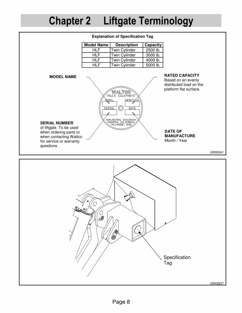
IMPORTANT:
All of the following are to be checked and verified before installation is complete.
A. Are all pivot pins secured with retaining bolt and lock washer?
B. Are all roll pins securely in place?
C. Does liftgate fold and unfold properly?
D. Does the platform meet the vehicle properly?
E. Do controls operate properly?
F. Are bed extension, mount frame, mount plates, dock bumpers, bumper braces, taillight guards and taillights all finish welded?
G. Are hydraulic hoses and fittings properly connected with no leaks?
H. Is battery cable attached and clamped tight?
I. Is circuit breaker installed at battery?
J. Are all electrical connections coated with dielectric grease?
K. Has hydraulic system been properly bled of all air?
L. Is pump reservoir full of oil and capped with breather plug?
M. Are all parts properly lubricated according to the lubrication instructions?
N. Do lights operate properly (Note: Lights must be installed in accordance with all applicable state and federal D.O.T. regulations)
O. Is license plate properly installed?
P. Are all decals properly in place and legible according to the decal placement drawings?
Q. Is pump cover installed and securely latched?
R. Is the owner’s manual in the vehicle?
S. Are 3/16” coil pin shims removed from platform?
WARNING: Do not use liftgate if any of the above are not checked and verified. If you have any questions not covered in this manual, contact your nearest Waltco distributor, or the nearest Waltco factory.
Page 35

Hand Held Remote Installation
80101485 EO6447 Rev.04
DRILL SOCKET HOLES
Using dimension shown, drill mounting holes in desired location for socket.
GR00036
INSTALL SOCKET
Assemble socket as shown.
Install wires according to colors: W = White (Raise) B or BK = Black (Lower) G = Green (Power)
GR02240
CONNECT WIRES TO PUMP UNIT
This step is for most liftgates, see next page for MDL series liftgate instructions. Route Control Cord into pump enclosure.
First connect Pump wires to Dual Control Adapter Harness as shown.
Connect both Control Cords to other ends of Adapter Harness as shown.
Note! Match wire connections male to female. Color of wire may vary.
GR02082
CONTROL
CORD
ADAPTOR
HARNESS
CONTROL
CORD
1-1/4” DIA.
7/32” DIA.
SOCKET
Page 36

Hand Held Remote Installation
80101485 EO6447 Rev.04
LPF Liftgate Instructions
Loosen cover bolt and remove Access Cover from center of Mount Tube. Remove Plastic Plug in top of Mount Tube and insert Strain Relief Fitting through the same hole. Tighten plastic Mounting Nut.
MOUNTINGNUT
STRAIN RELIEF
PLUG
GR00335
Remove Strain Relief cap nut and slide cap nut over Control Cord. Insert Control Cord into Mount Tube through Strain Relief, pushing one wire connector through at a time.
GR00336
Route Control Cords behind Battery Cable, keeping them close to back wall of Mount Tube and away from battery cable stud (Contact between any connectors and battery cable stud could result in a short circuit). Connect both Control Cords to three way Dual Control Adapter Harness.
NOTE: Match wire connections male to female. Color of wire may vary
BATTERYCABLE
CONTROLCORDS
ADAPTERHARNESS
GR00337
Pull unsupported lengths of Control Cord out of Mount Tube and thread Strain Relief cap nuts on snuggly. Do not over-tighten cap nuts, as this may damage the wires. Using 8” cable ties provided, secure Control Cords to Hose Fittings as shown. Secure Control Cords to vehicle with 16” cable ties.
CABLE TIES
GR00338
Page 37

Hand Held Remote Installation
80101485 EO6447 Rev.04
MDL, MDLBG, SB, PTN, SB & DT Liftgate Instructions:
Route Control Cord 10099332 into crossbeam box.
Disconnect green wire of existing control switch from valve solenoid.
Connect 10098429 to valve solenoid.
Connect green wires on existing control switch and on 10099332 to 10098429 as shown.
Connect white and black wires on 10099332 to same places the black and white wires on existing control switch connect.
Note! Match wire connections male to female. Color of wire may vary.
GR02804
Page 38

Auxiliary Battery Kit w/Dual Cables 80101569
DETERMINE BATTERY LOCATION AND CABLE ROUTING Determine where auxiliary battery box will be mounted on the vehicle.
For trucks your installation will use cables supplied with liftgate.
For trailers additional cables are supplied with the trailer kit.
GR02768
Locate battery box in a suitable location under the vehicle body. Weld hanger channel to body crossmembers. Install batteries into box.
GR02769
Install #1 ga. power and ground cables to liftgate pump unit per liftgate instructions.
Route cables along chassis frame towards auxiliary battery box, securing them every 24” with cable ties provided.
Do not connect any cables to batteries at this time.
Be certain cables are protected with grommets when passing through metal holes or over sharp edges.
Battery Box
Hanger Channel
Body Crossmembers
Pump Auxiliary Batteries
Vehicle Batteries
Auxiliary Batteries
Pump
Page 39

Auxiliary Battery Kit w/Dual Cables 80101569 Cut cables to required length. Use remaining length of cables to connect from auxiliary batteries to vehicle batteries (truck applications only, trailers will use additional 0 ga. cables). Install terminal lugs on ends of cables as shown below.
Protect wires from any sharp edges or holes that may abrade insulated covering of wires.
Secure battery cable so it does not come near, or in contact with, other vehicle wiring, fuel lines, brake lines, air hoses, exhaust system, etc.
Install cable lugs as shown below.
GR01961
INSTALLATION OF TERMINAL LUG
Strip 7/8” to 1” of insulation from end of cable.
Slide heat shrinkable tubing onto cable.
Insert bare wire into compression nut until it seats.
IMPORTANT: Be sure to use correct compression nut, use 1&2 gauge nut for 1 gauge cable, use 0 gauge nut for 0 gauge cable.
Note: Copper wire should be flush with, or slightly past nut
7/8” to 1”
Heat shrinkable tubingbefore installation
GR00299
Grip nut with wrench and turn terminal until nut seats
GR00300
AUXILIARY OR VEHICLE BATTERIES
Compression Nut
Page 40

Auxiliary Battery Kit w/Dual Cables 80101569
Position heat shrinkable tubing over terminal and end of cable.
Note: Red heat shrink is applied to power cable and black heat shrink to ground.
Shrink tubing using electric heat gun or torch.
Note: To reduce chance of damaging tube and cable, a heat gun is recommended
Apply sufficient heat to produce thin bead of sealant all around tube edges
Heat ShrinkableTubing
Beads of Sealant
GR00301
Page 41

Auxiliary Battery Kit w/Dual Cables 80101569 INSTALLATION OF CIRCUIT BREAKER(S) Batteries on a truck will require circuit breakers at both the auxiliary batteries and the vehicle batteries.
Locate and mount circuit breaker directly to batteries using copper terminal link supplied.
Circuit breakers must be mounted to give good protection against any objects coming into contact with circuit breaker terminals and causing a short. Positions must also be readily accessible to reset breakers.
Note: Circuit Breaker is to rest solidly on battery to prevent vibration during transit.
If unable to connect circuit breaker direct to batteries, an optional 24”, maximum length, 2 Ga. battery cable may be used.
Connect cables as shown.
Apply a generous amount of Dielectric Grease to all Positive (Hot) Battery terminals and Circuit Breaker terminals.
Install circuit breaker decal, 80100829, near the circuit breaker.
For trucks, use remaining length of cables supplied with liftgate, and route from auxiliary batteries to vehicle batteries.
Install terminal lugs on cables as required per previous instructions.
Install circuit breaker and cables to vehicle batteries per previous instructions.
Protect wires from any sharp edges or holes that may abrade insulated covering of wires.
Secure battery cable so it does not come near, or in contact with, other vehicle wiring, fuel lines, brake lines, air hoses, exhaust system, etc.
IMPORTANT: DO not operate liftgate until Mounting Bar has been removed from liftgate.
See below for trailer applications.
GR01962
Ground (-) Cables
Terminal Links
Cable to vehicle batteries or nose of trailer
Circuit Breaker
Power (+) Cables
Cable from liftgate
Circuit Breaker Decal
Circuit Beaker
Page 42

Auxiliary Battery Kit w/Dual Cables 80101569
Trailer applications:
Using 0 ga. cable, supplied with trailer kit, cut two (2) lengths to reach from auxiliary batteries to nose of trailer.
Install compression cable lugs as shown earlier.
For trailer applications.
Install dual pole socket in nose of trailer. Drill 1-3/4” hole in trailer and mount with hardware provided.
Route cables from auxiliary batteries to nose of trailer.
Install cables to socket as shown.
IMPORTANT: Be sure to orientate cables as shown, power (+) to the left, ground (-) to the right.
Power (charge) cable from tractor batteries to trailer must also be protected with a 150 amp circuit breaker at the tractor batteries.
GR02770
EO6663 Rev 02 9-8-11
Dual Pole Socket
Attach Ground (-) Cable This Side
Attach Power (+) Cable This Side
Cables made from 0 ga. cable
Page 43

80101550 EO6434R Rev. 02
Dual Control Switch, Installation Instructions
For Kit 80000437
Note: Kit may include additional parts not used in all installations
Locating and Mounting Switch
Locate a position for Switch such that operator has a clear view of entire Platform area and will not be in the area that liftgate passes through.
IMPORTANT Verify that Control Cord is long enough to reach pump unit before advancing to the
next step.
Using Switch Mounting Template or diagram to the right, drill two fastener holes with a 7/32” drill bit.
If Control Cord will be run through a hole in the side of the truck, drill ½” dia hole and remove all sharp edges and insert a grommet.
Mount Switch with ¼” Self-tapping screws provided.
GR02652
GR02653
Route Control Cord into pump enclosure.
First connect Pump wires to Dual Control Adapter Harness as shown.
Connect both Control Cords to other ends of Adapter Harness as shown.
NOTE: Match wire connections male to female. Color of wire may vary.
GR02654
CONTROL CORD
ADAPTER HARNESS
CONTROL CORD
¼” SELF-TAPPING SCREWS
Page 44

Installation of Cab Shut Off Switch
80101363 REV 04 09-08-11
Install cab shut off switch and shut off switch decal in convenient location in vehicle cab.
GR00379
Remove fuse line from motor solenoid. Unplug fuse line (or cut if required) from switch and save for later installation. Connect green 16 ga. cab shut off wire to switch. Install supplied bullet connector onto switch wire, if required. GR02087
Run green 16 ga. cab shut off wire to cab shut off switch.
Cut off excess wire and connect to cab shut off switch with supplied #10 ring terminal.
Re-using the fuse line, attach supplied bullet connector if not already equipped. Connect to excess 16 ga. wire.
Run excess 16 ga. wire from vehicle battery to cab shut off switch. Fuse end to be toward battery.
Note: Do not connect to battery at this time.
Connect 16 ga. wire to cab shut off switch with supplied #10 ring terminal.
Connect fuse line to battery with attached 3/8” ring terminal.
Important: Heat shrink all connectors.
GR00716
To switch green wire
Fuse
Excess Wire
Bullet Connector
Battery Cable
Switch
Cab Shut Off Switch
Remove
To Battery
16 Ga. Cab Shut Off Wire
Decal
Motor Solenoid
Cab Shut Off Switch
NOTE: Circuit Breaker to rest solidly on battery to prevent vibration during transit
Page 45

EM / EM-TC UNDER-RIDE INSTALLATION
80101565 E.O. 6309Y Rev. 01
INSTALLATION OF UNDER-RIDE BUMPER
Align slots of under-ride bumper weldment with holes in lift arm at the desired height.
Install supplied 5/8” bolts, washers (2 per instance), and nuts. Three (3) must be used on each side of bumper as shown.
Torque to 100 ft-lbs minimum.
Operate liftgate to ensure proper ground clearances through complete cycle.
NOTE: To be compliant with Federal DOT Standard, Part 571.224, bumper must be installed per above directions and cannot exceed 22” of Ground Clearance in stored position.
GR02734
GROUND CLEARANCE
INSTALL 5/8 HEX BOLT, WASHERS, AND NUT. THREE (3) TIMES EACH SIDE AS SHOWN.
Page 46

HLF WALK RAMP KIT INSTALLATION INSTRUCTIONS
80101571 E.O. 6708 Rev. 06
HLF WALK RAMP KIT *This kit is for bed height ranges of 49” fully laden to 60” empty. **Additional bed height restrictions may apply.
Walk Ramp Clearances
Check clearances prior to installing walk ramp kit.
Note Walk Ramp “A” Dim
Remove any items that cause interference.
This kit includes Walk Ramp Latch, Up-Stops, and Mounting Bracket.
GR02804
Assemble Walk Ramp Bracket and Up-Stops to Bed Extension Bolt Walk Ramp Bracket to Bed Extension, as shown, with supplied 3/8” bolts, nuts, and washers. See chart on next page. Note: Walk Ramp Bracket goes outside of support bars of Bed Extension. Bolt on Up-Stop Pads to Bed Extension, as shown, with supplied 5/16” bolts, nuts, and washers. Note: Failure to locate up-stop pads will result in damage to liftgate and walk ramp.
GR02805
Bolt Walk Ramp Bracket to outside of support bars as shown. See Chart for proper mounting.
Up-Stop Pads
22" MIN - 32" MAX(RAMP WIDTH)
A + 3/4 A
20 12
214
2712
112
Page 47

HLF WALK RAMP KIT INSTALLATION INSTRUCTIONS
80101571 E.O. 6708 Rev. 06
Mounting Chart for Walk Ramp Bracket Based on the walk ramp “A” dim and type of walk ramp, mounting the walk ramp bracket varies slightly.
Walk Ramp Type
A = 8-1/2” A = 9”
Bracket Hole Set
Bed Ext. Hole Set
Bracket Hole Set
Bed Ext. Hole Set
Standard 2 1 1 1
Spring Assist 2 2 1 2
IMPORTANT: For every inch the walk ramp is lowered beyond 8-1/2”, the equal amount must be added to minimum laden bed height.
GR02858
Additional Spacers If “A” dim is 8-1/2” with standard walk ramp, no spacers needed. If “A” dim is 8-1/2” with spring assist walk ramp, add Walk Ramp Guide Spacers and one (1) Up-Stop spacer at each location. If “A” dim is 9” with standard walk ramp applies, add one (1) Up-Stop Spacer to each location. If “A” dim is 9” with spring assist walk ramp applies, add Walk Ramp Guide Spacers and two (2) Up-Stop spacers at each location.
IMPORTANT: For every inch the walk ramp is lowered beyond 8-1/2”, the equal amount must be added to minimum laden bed height.
GR02857
Assemble Platform Brackets to Platform Frame Orientate the Platform Bracket with short leg towards the platform hinge. Bolt on Platform Brackets with supplied ½” self tapping bolts.
GR02806
2
2 14
Short Leg of Platform Bracket Towards Platform Hinge
Bolt to existing frame plate
Platform Hinge
Walk Ramp Guide Spacer (2 places)
Up-Stop Spacers (2 places)
Bed Ext Hole Set 1
Bed Ext Hole Set 2
Bracket Hole Set 1
Bracket Hole Set 2
Page 48

HLF WALK RAMP KIT INSTALLATION INSTRUCTIONS
80101571 E.O. 6708 Rev. 06
Adjustment of Parting Bar The Parting Bar must be located in the fully retracted position as show to right.
Tighten nuts and bolts to 50 ft lbs.
GR02799
Final Inspection After all components from Walk Ramp Kit have been installed, carefully run liftgate through a complete cycle to check for interferences. Check platform storage: - Ensure Up-Stops contact Platform Brackets - Ensure liftgate does not extend beyond steel of
Dock Bumper Check platform operation: - Ensure platform does not contact Walk Ramp
Bracket nor Up-Stops when opening and closing. - If contact does occur, the Parting Bar was not
adjusted or the bed height is too low.
GR02808
Check Up-Stop contact & liftgate location
Check for contact while opening and closing liftgate
Fully retracted Parting Bar
Page 49

Chain Anchor Kit Installation Instructions 80101620
EO6903 Rev 01 11/5/12
CHAIN ANCHOR INSTALLATION Remove first bolt of platform on curb side of vehicle. Locate Chain Anchor into side plate hole and align bolt holes as shown. Re-install first bolt of platform and tighten to 30-35 ft lbs.
GR02939
TRANSIT CHAIN INSTALLATION Bolt Transit Chain to Bed Extension with 3/8-16 x 1-1/4” Gr 8 bolt, Washer and Locknut as shown. Note: If Dock Bumpers are included, they must be installed prior to installing Transit Chain.
GR02898
Transit Chain
Hardware
First bolt of platform Tighten to 30-35 ft lbs
Chain Anchor
Page 50

80101389 EO 5534A Rev 02
Chapter 8 How To Order Parts
Repairs should be made only by authorized mechanics using WALTCO Replacement parts. When ordering repair or replacement parts, please include all the information asked for below. If this information is not available, a complete written description or sketch of the required part will help WALTCO identify and deliver the needed part to you. ________________________________________________________________
THE FOLLOWING INFORMATION MUST BE INCLUDED:
1. SERIAL NUMBER - [WALTCO liftgate serial numbers can be found on the Specification Tag attached to the mount frame. (On older units the Specification Tag is located on the side or bottom of the platform.)]
2. MODEL NUMBER - [Or capacity] 3. PLATFORM SIZE ________________________________________________________________
THEN INCLUDE THE FOLLOWING INFORMATION:
4. PART NUMBERS 5. DESCRIPTION 6. QUANTITY REQUIRED ________________________________________________________________
MAIL, E-MAIL OR PHONE YOUR REQUEST TO:
Waltco Truck Equipment Co. 285 Northeast Avenue Tallmadge, OH 44278
1-800-411-5685 FAX: 1-800-411-5684
E-MAIL: [email protected]
ALL PARTS ARE F.O.B. FROM THE SHIPPING FACTORY ________________________________________________________________
PLEASE NOTE:
To assure you of continuing and effective quality control, our warranty policy permits replacement of hydraulic cylinders, valves and motor pump units when their factory seals are intact. Parts under warranty will be exchanged promptly after careful inspection of the returned assemblies.
________________________________________________
Page 51

This page intentionally left blank.
Page 52

Every vehicle that has a WALTCO Liftgate must have legible WARNING AND OPERATION DECALS clearly posted on the vehicle and an OWNER’S MANUAL in the vehicle at all times as a guide for proper operation and maintenance.
Additional WARNING DECALS, OPERATION DECALS and OWNER’S MANUALS can be obtained from WALTCO TRUCK EQUIPMENT COMPANY.
____________________ NOTE:
When ordering, give model
and serial number of the liftgate. ____________________
Page 53
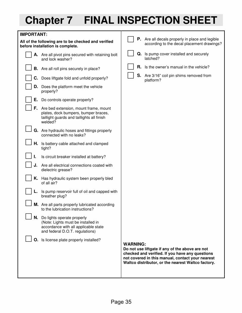
IMPORTANT
WARNING Improper operation and maintenance of this liftgate could result in severe personal injury or death.
Read and understand the contents of this manual and all warning and operation decals before operating and/or performing maintenance on this liftgate.
For SAFETY information on this liftgate see Chapter 1 of this manual
80101520 EO6156
Rev 01
Page 54


![Nouredine HADJSAID HLF V1 2 - HLF Giant Grenoble ...hlf-giant-grenoble.org/.../2017/10/...Nouredine_Hadjsaid_Grenoble.pdf · 6rph whqghqflhv rq hqhuj\ v\vwhpv ¾,qwhjudwlqj ghfhqwudol]hg](https://img.dokumen.tips/doc/110x75/5b54a7cb7f8b9ae30b8d8138/nouredine-hadjsaid-hlf-v1-2-hlf-giant-grenoble-hlf-giant-6rph-whqghqflhv.jpg)