Embed Size (px)
Citation preview

INSTALLATION MANUAL FOR
SR-1000 STANDALONE INTEGRATED MEDIA BLOCK™
Version 17.0
March 15, 2018

- 1 - March 15, 2018
Installation Manual for SR-1000 Standalone Integrated Media Block™
TABLE OF CONTENTS
Table of Contents 1. INTRODUCTION .................................................................................................................6
1.1. Equipment List ......................................................................................................................... 7
2. INSTALLING SR-1000 INTO THE PROJECTOR ........................................................................8
2.1. Remove existing interface board/placeholders from the projector ....................................... 9
2.1.1. Barco Projector Placement ................................................................................................... 9
2.1.2. Christie Projector Placement .............................................................................................. 10
2.1.3. NEC Projector Placement ................................................................................................... 10
2.2. Installing the SR-1000 into the projector .............................................................................. 11
2.3. Projector Network ................................................................................................................. 11
3. CONNECTING PORTABLE STORAGE/ENTERPRISE STORAGE WITH THE SR-1000 .................. 12
3.1. Connecting the Portable Storage .......................................................................................... 12
3.2. Connecting the Enterprise Storage........................................................................................ 12
4. SR-1000 WEBUI ACCESS ................................................................................................... 14
5. SR-1000 IP ADDRESS SETUP ............................................................................................. 15
5.1. IMB Network Setup ............................................................................................................... 15
6. STORAGE CONFIGURATION .............................................................................................. 17
7. SERIES 2 PROJECTOR SETUP ............................................................................................. 19
7.1. IMB Marriage and Clearing the Service Door Tamper from the SR-1000 ............................. 19
7.2. Barco Series 2 Projector Setup .............................................................................................. 20
7.3. NEC Series 2 Projector ........................................................................................................... 21
7.4. Christie Series 2 Projector ..................................................................................................... 22
7.5. 3D settings for Series 2 projectors ........................................................................................ 24
8. TIME ZONE SETUP ........................................................................................................... 25
9. CONTENT INGEST MANAGEMENT SETUP .......................................................................... 26
9.1. Content ingest from USB disk ................................................................................................ 26
9.2. Content ingest from FTP ........................................................................................................ 27
10. AUDIO SETUP ................................................................................................................ 28
11. SUBTITLES ..................................................................................................................... 30
12. AUTOMATION SETUP ..................................................................................................... 31
12.1. Automation setup for server GPIO ...................................................................................... 31

- 2 - March 15, 2018
Installation Manual for SR-1000 Standalone Integrated Media Block™
TABLE OF CONTENTS
12.2. Automation setup for projectors ......................................................................................... 32
12.3. Automation setup for eCNA devices ................................................................................... 33
12.4. Automation setup for JNIOR devices ................................................................................... 34
12.5. Automation setup for Christie ACT devices ......................................................................... 35
12.6. Automation setup for Dolby devices ................................................................................... 36
12.7. Automation setup for USL DAX devices ............................................................................... 37
12.8. Automation setup for USL JSD devices ................................................................................ 38
13. COMPONENT ENGINNERING TA-10 SETUP ...................................................................... 39
14. TESTING PROCEDURES FOR QC AFTER INSTALLATION ..................................................... 39
15. APPENDIX...................................................................................................................... 40
15.1. AES Audio and GPIO Pinout ................................................................................................. 40
15.2. GPIO Power Details .............................................................................................................. 40

- 3 - March 15, 2018
Installation Manual for SR-1000 Standalone Integrated Media Block™
User Manual
Thank you for purchasing a GDC SR-1000 Standalone Integrated Media Block™ from GDC Technology Limited.
To ensure proper operation and to maximize value of the SR-1000, please review this Installation Manual. It will guide you through all the features and benefits of the new SR-1000 Standalone Integrated Media Block™.
COPYRIGHT NOTICE
Copyright © 2018 by GDC Technology Limited
All rights reserved. No part of this manual may be copied or distributed, transmitted, transcribed, stored in a retrieval system, or translated into any human or computer language, in a form or by any means, electronic, mechanical, photocopying, recording, magnetic, optical, manual or otherwise, or disclosed to third parties without prior written permission of GDC Technology Limited.
MANUAL DISCLAIMER
This manual is made with version 17.0 and there might be slight differences depending on the software version the IMB is running. The contents, features and specifications stated in this manual are subject to change without notice due to continuous product development and improvements. In no other event shall GDC Technology Limited be liable for any loss of profit or any other commercial damages, including but not limited to special, consequential, or other damages.
FCC COMPLIANCE STATEMENT
This device complies with Part 15 of the FCC Rules. Operation is subject to the following two conditions: (1) this device may not cause harmful interference, and (2) this device must accept any interference received, including interference that may cause undesired operation.
NOTE: This equipment has been tested and found to comply with the limits for a Class A digital device, pursuant to Part 15 of the
FCC Rules. These limits are designed to provide reasonable protection against harmful interference when the equipment is operated in a commercial environment. This equipment generates, uses, and can radiate radio frequency energy and, if not installed and used in accordance with the instruction manual, may cause harmful interference to radio communications. Operation of this equipment in a residential area is likely to cause harmful interference in which case the user will be required to correct the interference at his own expense.

- 4 - March 15, 2018
Installation Manual for SR-1000 Standalone Integrated Media Block™
CONTACTS AND OFFICES
CONTACTS AND OFFICES
Website: www.gdc-tech.com Email: [email protected] 24/7 Engineering Support Hotline:
Hong Kong (Headquarters)
China (Beijing)
China (Shenzhen)
Spain(Barcelona)
Unit 1-7, 20th Floor, Kodak House II, 39 Healthy Street East, North Point, Hong Kong Tel: +852 2507 9555
Rm. 609-618, Office Building,20# Xinde Street, Xicheng District, Beijing, P.R. China 100088 Tel: +86 10 6205 7040
Room A701, 7/F, Languang Technology Building, No.7 Xinxi Road, North Zone, HighTech Park, Nanshan District, Shenzhen, China Tel: +86 755 8608 6000
C/ Esteve Terradas, nº 27, esc. D, Despacho 1 08023 Barcelona, Spain Tel: +34 93 159 51 75
Peru (Lima)
USA (Los Angeles)
Brazil (São Paulo)
Singapore
Calle Manuel Miota 170,
Miraflores Lima 18, Peru
Tel: +51 1 340 5146
1016 West Magnolia Boulevard Burbank, CA 91506, USA Tel: +1 818 972 4370 / +1 877 743 2872 (Toll Free)
Av. Antônio Carlos Comitre, 540, 3º andar, Conjunto 31, Campolim, Sorocaba / São Paulo, CEP 18047-620, Brasil
Tel: +55 15 33269301
10 Ubi Crescent, Ubi Tech Park, Lobby B, #06-25 Singapore 408564 Tel: +65 6222 1082
North America +1 877 743 2872 (Toll Free) Latin America +52 55 8851 1198 Europe +34 928 912 295 China +86 400 886 0966 (Toll Free) North Asia +852 3520 0920 India +91 022 4044 0500 South East Asia +65 6100 4328 Australia/
New Zealand
+61 407 040 744

- 5 - March 15, 2018
Installation Manual for SR-1000 Standalone Integrated Media Block™
CONTACTS AND OFFICES
Indonesia (Jakarta)
Japan (Tokyo)
India (Mumbai)
Mexico (Mexico City)
Total Building Lantai 4 Suite 0401, Jl. Letjen S. Parman Kav. 106A, Kel Tomang, Kec. Grogol Petamburan, Jakarta Barat 11440, Indonesia Tel: +62 21 2920 4691
3F, Kyobashi-Chuo Bldg, 1-14-7 Kyobashi Chuo-ku Tokyo 104-0031, Japan Tel: +81 3 5524 2607
Office No. B-207/208, Everest Chamber, Andheri Kurla Road, Marol, Andheri (East), Mumbai-400 059, India Tel: +91 22 4044 0500
Ave. Santa Fe 94, Torre A Piso 8, Col. Zedec Santa Fe, Alvaro Obregon, Mexico, D.F., C.P. 01210 Mexico Tel: +52 55 8851 1198/ ___+52 55 8851 1165
United Arab Emirates (Dubai)
Business Centre, Dubai World Central, PO Box 390667, Dubai UAE

- 6 - March 15, 2018
Installation Manual for SR-1000 Standalone Integrated Media Block™
1. INTRODUCTION
1. INTRODUCTION
This document is a guide through the process of setting up the SR-1000 with the projector, audio system, and automation devices used in cinema theatres. In this manual, the SR-1000 WebUI is used to configure the SR-1000. The Dashboard of the SR-1000 WebUI is shown below (see Figure 1).
Figure 1 Dashboard tab.

- 7 - March 15, 2018
Installation Manual for SR-1000 Standalone Integrated Media Block™
1.INTRODUCTION
1.1. Equipment List
This section provides a suggested installation configuration of GDC SR-1000 for reference. Please contact
our sales representative to specify the accessories needed for the installation.
The SR-1000 Packaging Includes:
Item Qty Photo
SR-1000 Unit with projector coverplate 1
RJ45 AES Audio Cable 1#
RJ45 GPIO Cables 2#
Network Cable 1
RJ45 to DB25 Audio Converter #
# Subject to actual configuration. Please specify with our sales representative.

- 8 - March 15, 2018
Installation Manual for SR-1000 Standalone Integrated Media Block™
2.INSTALLING SR-1000 INTO THE PROJECTOR
2. INSTALLING SR-1000 INTO THE PROJECTOR Note: If the projector comes with the GDC IMB pre-installed, the instructions in this section can be skipped.
This section of the manual describes the physical installation of the SR-1000 into the projector. If the projector does not have the GDC SR-1000 installed, follow the steps below to install the SR-1000 into the projector.
Figure 2 SR-1000 Standalone IMB®

- 9 - March 15, 2018
Installation Manual for SR-1000 Standalone Integrated Media Block™
2.INSTALLING SR-1000 INTO THE PROJECTOR
2.1. Remove existing interface board/placeholders from the projector
Before installing the SR-1000, check the figures below to ensure proper placement.
2.1.1. Barco Projector Placement Figure 3 shows an interface board (with SMPTE 292 inputs) connected to a Barco projector. This board must be removed in order to install the SR-1000.
Figure 3 Remove interface board from Barco projector.
Figure 4 SR-1000 Placement on Barco projector.

- 10 - March 15, 2018
Installation Manual for SR-1000 Standalone Integrated Media Block™
2.INSTALLING SR-1000 INTO THE PROJECTOR
2.1.2. Christie Projector Placement Figure 5 shows the location where the SR-1000 should be installed on a Christie projector.
Remove any existing interface boards or placeholder faceplates from this position before
installing the SR-1000.
Figure 5 SR-1000 Placement on Christie projector.
2.1.3. NEC Projector Placement Figure 6 shows the location where the SR-1000 should be installed on a NEC projector. Remove any existing interface boards or placeholder faceplates from this position before installing the SR-1000.
Figure 6 SR-1000 Placement on NEC projector.
Note: When installing the SR-1000 into any NEC projector, it is recommended to install it into the
top slot of the projector. If the SR-1000 is installed into the bottom slot, the board runs the risk of
coming in contact with the IMB enclosure.
Please refer to the projector manuals for more details on preparing the projector for SR-1000
installation.

- 11 - March 15, 2018
Installation Manual for SR-1000 Standalone Integrated Media Block™
2.INSTALLING SR-1000 INTO THE PROJECTOR
2.2. Installing the SR-1000 into the projector Please make sure the projector is powered off before installing the SR-1000 on the projector. Note: Please check the SR-1000 for any physical damage like loose or burnt component before installing it into the projector.
Figure 7 Installing the SR-1000 into the projector.
Insert the SR-1000 as shown in Figure 7. The SR-1000 should slide into the projector on the rails
provided by the IMB slot, and the SR-1000 faceplate should be flush with the other existing
faceplates once properly inserted.
2.3. Projector Network
Connect the provided Cat 5e LAN cable from the SR-1000 Gigabit 2 port to cinema network.
Please see Section 5 for IP network instructions after the SR-1000 is installed.

- 12 - March 15, 2018
Installation Manual for SR-1000 Standalone Integrated Media Block™
3.CONNECTING PORTABLE STORAGE/ENTERPRISE STORAGE WITH THE SR-1000
3. CONNECTING PORTABLE STORAGE/ENTERPRISE STORAGE WITH THE SR-1000
For installation of Portable Storage or Enterprise Storage, please refer to Installation Manual for Portable Storage and Enterprise Storage.
3.1. Connecting the Portable Storage
1. Take out the adapter from the packaging and connect to the DC power connector.
2. Connect the eSATA cable to the back panel for data transfer.
Figure 8 Connect eSATA cable to the Portable Storage.
Making the connections to the SR-1000
3. Insert the eSATA cable into the SR-1000 eSATA port.
Figure 9 Insert eSATA cable into SR-1000 eSATA port.
NOTE: To use Portable Storage as the content source, it MUST be connected to the eSATA port of the SR-
1000 board.
3.2. Connecting the Enterprise Storage

- 13 - March 15, 2018
Installation Manual for SR-1000 Standalone Integrated Media Block™
3.CONNECTING PORTABLE STORAGE/ENTERPRISE STORAGE WITH THE SR-1000
1. Take out the power cord from the packaging and connect to the power connector of
Enterprise Storage.
2. Connect the eSATA cable to the back panel of the Enterprise Storage for data transfer.
Figure 10 Connect eSATA cable to the Enterprise Storage.
Making the connections to the SR-1000
3. Insert the eSATA cable into the SR-1000 eSATA port.
Figure 11 Insert eSATA cable into SR-1000 eSATA port.
NOTE: To use the Enterprise Storage as the content source, it MUST be connected to the eSATA port of
the SR-1000 board.

- 14 - March 15, 2018
Installation Manual for SR-1000 Standalone Integrated Media Block™
4. SR-1000 WEBUI ACCESS
4. SR-1000 WEBUI ACCESS
The SR-1000 uses a web-based user interface. The following steps show how to access the SR-
1000 WebUI.
1. To operate the SR-1000, connect the SR-1000 IMB to a laptop/PC, and make sure that
the IMB and laptop/PC are on the same network.
2. SR-1000 WebUI can be accessed by a web browser (Google Chrome or Mozilla Firefox
are recommended).
3. Enter the IP address of the SR-1000 on the web browser to access the login page on the
WebUI.
4. There are 3 levels of users available. Select User, Technician or Maintenance, and enter
the password to access the SR-1000.
Figure 12 SR-1000 Login Page

- 15 - March 15, 2018
Installation Manual for SR-1000 Standalone Integrated Media Block™
5. SR-1000 IP ADDRESS SETUP
5. SR-1000 IP ADDRESS SETUP
The IP address of the SR-1000 IMB will need to be set for proper operation.
5.1. IMB Network Setup
Change the IP addresses of the SR-1000 using the following steps:
1. Login as Maintenance user.
2. Under the Configuration tab in the menu, click the System subtab.
3. Go to Network Configuration section.
4. Enter the settings for Subnet Mask, Gateway, and IMB Ethernet 2.
Figure 13 Network Configuration setting
5. Once the settings have been entered, click Validate IPs.

- 16 - March 15, 2018
Installation Manual for SR-1000 Standalone Integrated Media Block™
5. SR-1000 IP ADDRESS SETUP
6. If all of the IP addresses are valid, the popup window below will appear:
Figure 14 Network Configuration setting
7. Click OK to exit.
8. Click Save to save the settings.

- 17 - March 15, 2018
Installation Manual for SR-1000 Standalone Integrated Media Block™
8. SERIES 2 PROJECTOR SETUP
6. STORAGE CONFIGURATION SR-1000 Storage can be configured using the Configuration tab’s Storage subtab. 1. Go to IMB Storage section and select the required Storage Type option.
2. The following options are available:
NAS – Connect to NFS server for storage
CineCacheTM – Use CineCache for storage (For SR-1000 with CineCache installed
only)
PSD – Use Portable Storage or Enterprise Storage
Figure 15 IMB Storage setting

- 18 - March 15, 2018
Installation Manual for SR-1000 Standalone Integrated Media Block™
8. SERIES 2 PROJECTOR SETUP
3. Go to Dashboard, click Restart, followed by OK to confirm. This is to ensure all components
in the SR-1000 are able to detect the selected storage after restart.
4. The SR-1000 will restart and use the selected option for storage.
Figure 16 Dashboard tab
Figure 17 Restart window

- 19 - March 15, 2018
Installation Manual for SR-1000 Standalone Integrated Media Block™
8. SERIES 2 PROJECTOR SETUP
7. SERIES 2 PROJECTOR SETUP
To play content with the SR-1000 in a projector, follow the instructions below:
IMB Marriage must be done,
Service door tamper must be cleared
The projector must be set up according to the requirements of the projector manufacturer.
7.1. IMB Marriage and Clearing the Service Door Tamper from the SR-1000
Follow the steps below to perform the marriage between the SR-1000 and to clear the service door tamper on the SR-1000:
1. Under the Configuration tab in the menu, click the System subtab.
2. Go to Clear IMB Tampers section.
3. Click Marry to perform the marriage of the projector and the SR-1000.
4. Click Close to clear the door tamper errors with the projector
5. After the Marriage is performed and the tampers are cleared, green Married and
Closed buttons will be shown respectively (as seen in Figure 18).
Figure 18 Clear IMB tampers setting

- 20 - March 15, 2018
Installation Manual for SR-1000 Standalone Integrated Media Block™
8. SERIES 2 PROJECTOR SETUP
7.2. Barco Series 2 Projector Setup
No system configuration is required for Barco Series 2 projector to work with the SR-1000. The
Service Door/Marriage Tamper on the server must be cleared before the SR-1000 can be used for
playback.
In order to use the SR-1000 for content playback, the INPUT source of the projector macros should
be set to “Mediablock” (as shown in Figure 19). If the input file is not present, please download and
install the latest projector configuration files for your projector. For details, please refer to the
projector manual.
Figure 19 INPUT source settings on Barco Series 2 projector.

- 21 - March 15, 2018
Installation Manual for SR-1000 Standalone Integrated Media Block™
8. SERIES 2 PROJECTOR SETUP
7.3. NEC Series 2 Projector
In order to configure an NEC Series 2 projector to work with the SR-1000, the following steps must be taken:
1. Switch on the projector so that it is in STANDBY mode. 2. Use the Digital Cinema Communicator for S2 Windows software provided by NEC to
connect to the projector. 3. Select [Start] [Mode] [Service] and enter the Service password to activate
service mode operation. (as shown in Figure 20)
Figure 20 Service Mode on NEC Digital Cinema Communicator.
4. Select [Setup] [Option Slot] on the Digital Cinema Communicator and select IMB
for Slot B in Option Slot Setting. (as shown in Figure 21)
Figure 21 Option slot settings on NEC Digital Cinema Communicator.
5. Select [Start] [Power] [On] to power on the projector.
6. Clear the Service Door/Marriage Tamper on the SR-1000.
To use the SR-1000 for content playback, the INPUT source of the projector macros must be set
to IMB.

- 22 - March 15, 2018
Installation Manual for SR-1000 Standalone Integrated Media Block™
8. SERIES 2 PROJECTOR SETUP
7.4. Christie Series 2 Projector
In order to configure a Christie Series 2 projector to work with the SR-1000, the following steps must be taken:
1. Switch on the projector.
2. Log in to the [Marriage] account on the projector TPC. Select [Menu] [Login] (as shown in Figure 22).
Figure 22 Marriage account
3. Enter Username as [marriage] and its password and click [Login] button. (as shown
in Figure 23).
Figure 23 Marriage account login

- 23 - March 15, 2018
Installation Manual for SR-1000 Standalone Integrated Media Block™
8. SERIES 2 PROJECTOR SETUP
4. Select [Menu] [Administrator Setup] [Content Devices Configuration] (as
Shown in Figure 24)
Figure 24 Content Devices Configuration
5. Select [GDC] for the [IMB Installed]. (as shown in Figure 25)
Figure 25 Content Devices Configuration
6. Clear the Service Door/Marriage Tamper on the SR-1000.
To use the SR-1000 for content playback, the INPUT for projector channel must be set to [IMB-
Generic].

- 24 - March 15, 2018
Installation Manual for SR-1000 Standalone Integrated Media Block™
8. SERIES 2 PROJECTOR SETUP
7.5. 3D settings for Series 2 projectors
The 3D macros for Series 2 projectors should be configured with the following settings for “3D
Input Control”:
• 3D Sync Input Mode: Use ‘Line Interleave’ (first line=Left, second line=Right)
• L/R Display Reference: Not Used
• Frame Rate: 6:2
• L/R Display Sequence: Left (L1R1 L2R2)
The following shows 3D settings on a Christie projector as an example (see Figure 26).
Figure 26 3D macro settings for Christie Series 2 projectors.
The settings for 3D output control (‘3D Sync Polarity’, ‘Dark Time’, ‘Output Delay’ and ‘Phase
Delay’) should be customized according to the type of 3D system used (RealD, XpanD or
Dolby3D).

- 25 - March 15, 2018
Installation Manual for SR-1000 Standalone Integrated Media Block™
10. CONTENT INGEST MANAGEMENT SETUP
8. TIME ZONE SETUP
The SR-1000 may or may not arrive with the local time zone set. The following steps show how to
change the time zone on the server.
1. Under the Configuration tab in the menu, click the System subtab.
2. Go to Configure TimeZone section.
3. Select the Region/City in the dropdown menu of TimeZone Select.
4. Click Save to save the setting.
Figure 27 TimeZone setting

- 26 - March 15, 2018
Installation Manual for SR-1000 Standalone Integrated Media Block™
10. CONTENT INGEST MANAGEMENT SETUP
9. CONTENT INGEST MANAGEMENT SETUP
An ingest source must be configured before content can be transferred to the SR-1000. This
section shows the configuration for content ingest from two different source types. The same
steps can be used to set up content ingest sources using other sources.
9.1. Content ingest from USB disk
The following steps describe the content ingestion from an external USB hard drive:
1. Under the Content tab in the menu, click the Source subtab.
2. On the left column, select USB Drive.
3. Click Open to choose content to be ingested from the USB disk.
Figure 28 Content source setting
- 27 - March 15, 2018
Installation Manual for SR-1000 Standalone Integrated Media Block™
10. CONTENT INGEST MANAGEMENT SETUP
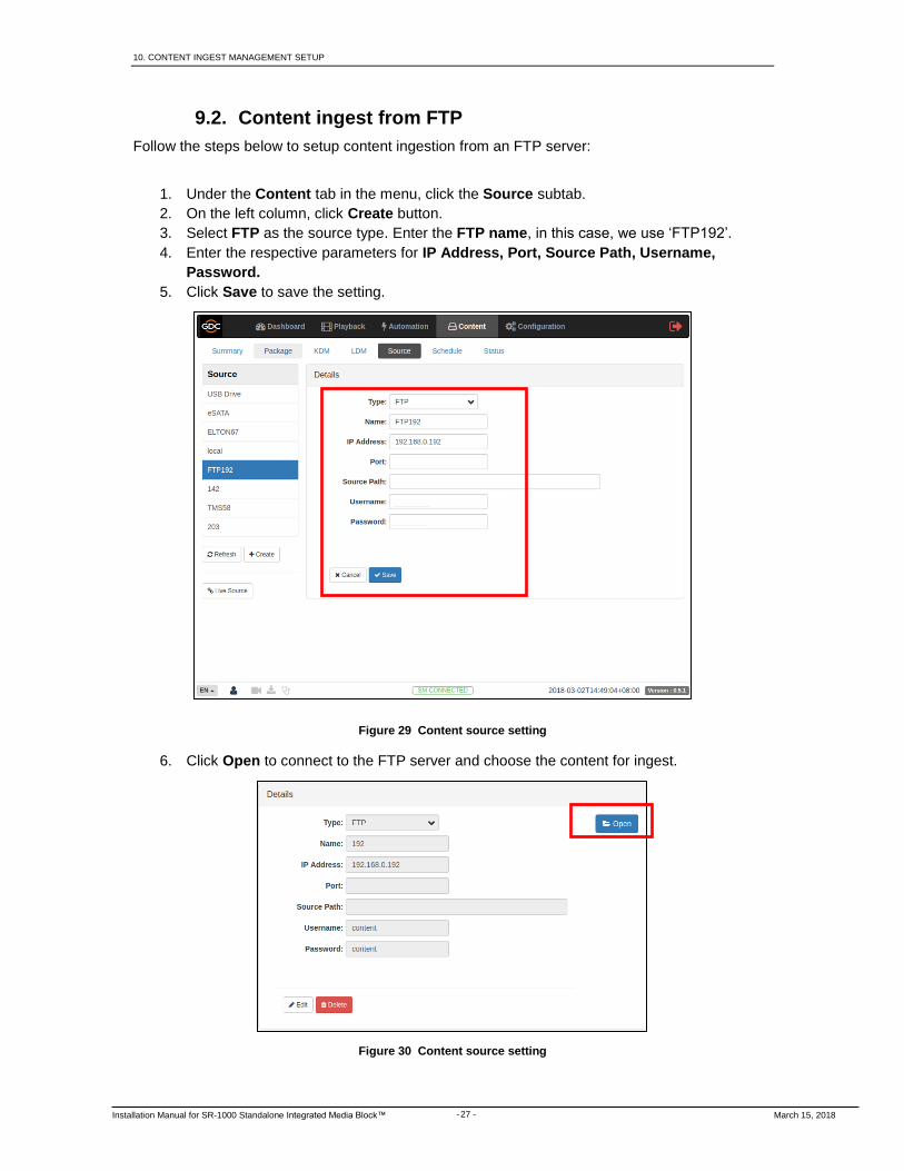
9.2. Content ingest from FTP
Follow the steps below to setup content ingestion from an FTP server:
1. Under the Content tab in the menu, click the Source subtab.
2. On the left column, click Create button.
3. Select FTP as the source type. Enter the FTP name, in this case, we use ‘FTP192’.
4. Enter the respective parameters for IP Address, Port, Source Path, Username,
Password.
5. Click Save to save the setting.
Figure 29 Content source setting
6. Click Open to connect to the FTP server and choose the content for ingest.
Figure 30 Content source setting

- 28 - March 15, 2018
Installation Manual for SR-1000 Standalone Integrated Media Block™
11. AUDIO SETUP
10. AUDIO SETUP
The SR-1000 features AES digital audio signal via two RJ45 Outputs. For compatibility with most
audio processors on the market, a standard RJ45 to DB25 connector is included in the packaging
(please refer to Figure 31).
Figure 31 RJ45 DB25 Audio Connector.
Figure 32 RJ45 DB25 pinout (For traditional audio connector).
Figure 33 RJ45 DB25 pinout (For CP750/JSD80 audio connector).

- 29 - March 15, 2018
Installation Manual for SR-1000 Standalone Integrated Media Block™
11. AUDIO SETUP
Figure 34 AES Audio RJ45 pinout.

- 30 - March 15, 2018
Installation Manual for SR-1000 Standalone Integrated Media Block™
12. SUBTITLES
11. SUBTITLES
It is recommended to use subtitle overlay for subtitle display. To do so, please check Subtitle
Overlay Option under the Playback subtab of the Configuration menu.
Figure 35 Subtitle setting

- 31 - March 15, 2018
Installation Manual for SR-1000 Standalone Integrated Media Block™
13. AUTOMATION SETUP
12. AUTOMATION SETUP
The SR-1000 is able to control external devices using its automation interface. This can be used
to automate repetitive tasks for the cinema operator to prevent user error.
12.1. Automation setup for server GPIO The SR-1000 GPIO automation device settings can be configured using the steps below:
1. Under the Automation tab in the menu, click the Device subtab.
2. On the left column, click IMBGPIO.
3. Enter the device name, Input Min Pulse width, Output Pulse Width.
Figure 36 Server GPIO setting
The output pulse width must be at least 100ms. If a different output pulse width is required, the value can be entered in the ‘Output Pulse Width’ setting. Click the [Save] button to save any changes made.

- 32 - March 15, 2018
Installation Manual for SR-1000 Standalone Integrated Media Block™
13. AUTOMATION SETUP
12.2. Automation setup for projectors The SR-1000 supports automation for Barco, Christie and NEC projectors. Follow the steps
below to configure a projector device in the server automation interface.
1. Under the Automation tab in the menu, click the Device subtab.
2. On the left column, click Create.
3. Select PROJECTOR as the device type. Enter the name of the projector, and click OK.
4. Enter the IP address of the projector device
5. Set the correct model of the projector. The port number will automatically change to the
default automation port number for the model. If the projector is a Series 2 projector,
check the ‘Series 2’ checkbox.
6. Enter Login and Password for the projector if required.
7. Click Save to save the settings.
Figure 37 Projector setting

- 33 - March 15, 2018
Installation Manual for SR-1000 Standalone Integrated Media Block™
13. AUTOMATION SETUP
12.3. Automation setup for eCNA devices
The SR-1000 supports the eCNA-10 automation system. Follow the steps below to configure an
eCNA device in the server automation interface.
1. Under the Automation tab in the menu, click the Device subtab.
2. On the left column, click create.
3. Select eCNA_IO as the device type. Enter the name of the eCNA device, and click OK.
4. Enter the IP address of the eCNA device.
5. The eCNA device has many cues available for automation. These cues can be enabled
or disabled by selecting them after clicking the buttons in Server events, eCNA
controls, eCNA status, and eCNA event report. All cues are disabled by default.
6. Click Save to save the settings.
Figure 38 eCNA device setting

- 34 - March 15, 2018
Installation Manual for SR-1000 Standalone Integrated Media Block™
13. AUTOMATION SETUP
12.4. Automation setup for JNIOR devices
The SR-1000 supports the JNIOR Ethernet I/O controller device. Follow the steps below to
configure a JNIOR device in the server automation interface.
1. Under the Automation tab in the menu, click the Device subtab.
2. On the left column, click create.
3. Select JNIOR_IO as the device type. Enter the name of the JNIOR device, and click
OK.
4. Enter the IP address of the JNIOR device.
5. The settings for Port, Login and Password are set to the default values for JUNIOR
device if left empty.
6. Click Save to save the settings.
Figure 39 JNIOR device setting

- 35 - March 15, 2018
Installation Manual for SR-1000 Standalone Integrated Media Block™
13. AUTOMATION SETUP
12.5. Automation setup for Christie ACT devices
The SR-1000 supports the Christie ACT automation device. Follow the steps below to configure a
Christie ACT device in the server automation interface.
1. Under the Automation tab in the menu, click the Device subtab.
2. On the left column, click Create.
3. Select ChristieACT as the device type. Enter the name of the ChristieACT device, and click OK.
4. Enter the IP address of the ChristieACT device. 5. The default setting for Port is displayed on the settings for the ChristieACT device.
Change this value if required. 6. Default control cues will be set up for a new ChristieACT automation device. Control
cues can be added or removed by clicking the + or – buttons. 7. Click Save to save the settings.
Figure 40 Christie device setting

- 36 - March 15, 2018
Installation Manual for SR-1000 Standalone Integrated Media Block™
13. AUTOMATION SETUP
12.6. Automation setup for Dolby devices
The SR-1000 supports automation for the Dolby sound processors. Follow the steps below to
configure a Dolby device in the server automation interface. For this example, the device refers to
the Dolby CP650 Sound Processor.
1. Under the Automation tab in the menu, click the Device subtab. 2. On the left column, click create. 3. Select DolbyCP650 as the device type. Enter the name of the Dolby CP650 device, and
click OK. 4. Enter the IP address of the Dolby CP650 device. 5. Click Save to save the settings.
Figure 41 Dolby device setting

- 37 - March 15, 2018
Installation Manual for SR-1000 Standalone Integrated Media Block™
13. AUTOMATION SETUP
12.7. Automation setup for USL DAX devices
The SR-1000 supports automation for USL DAX sound processor. Follow the steps below to
configure a USL DAX device in the server automation interface.
1. Under the Automation tab in the menu, click the Device subtab. 2. On the left column, click create. 3. Select USL-DAX as the device type. Enter the name of the USL DAX device, and click
OK. 4. Enter the IP address of the USL DAX device. 5. Click Save to save the settings.
Figure 42 USL DAX device setting

- 38 - March 15, 2018
Installation Manual for SR-1000 Standalone Integrated Media Block™
13. AUTOMATION SETUP
12.8. Automation setup for USL JSD devices
The SR-1000 supports automation for USL JSD-80 and JSD-100 sound processor. Follow the
steps below to configure a USL JSD device in the server automation interface.
1. Under the Automation tab in the menu, click the Device subtab. 2. On the left column, click create. 3. Select USL-JSD as the device type. Enter the name of the USL JSD device, and click
OK. 4. Enter the IP address of the USL JSD device. 5. Select the correct model (JSD-80 or JSD-100) of the device the server is connected to. 6. Click Save to save the settings.
Figure 43 USL JSD device setting

- 39 - March 15, 2018
Installation Manual for SR-1000 Standalone Integrated Media Block™
14. COMPONENTS ENGINEERING TA-10 SETUP
13. COMPONENT ENGINNERING TA-10 SETUP
The Component Engineering TA-10 can be used for theater automation with the SR-1000. It requires that the TA-10 be wired in a particular configuration. A wiring diagram can be seen in Figure 44. The TA-10 is connected to the SR-1000 using the server’s GPIO input/output port. Configure event labels with the GPIO device to trigger the TA-10.
Figure 44 Component Engineering TA-10 wiring diagram.
14. TESTING PROCEDURES FOR QC AFTER INSTALLATION
After the installation has been completed, it is necessary to test the following to ensure that the
SR-1000 has been properly installed:
1. Test the video playback capabilities of the SR-1000.
2. Test the audio playback capabilities of the SR-1000 and verify that all the channels are
working. Also check for any static noises.
3. Test the server’s ability to activate automation cues using test cues for lights, curtains,
sound and fire alarm.
4. Test the remote access capabilities of the server, including: Theater Management
System (TMS) access and network connectivity.

- 40 - March 15, 2018
Installation Manual for SR-1000 Standalone Integrated Media Block™
16. APPENDIX
15. APPENDIX
15.1. AES Audio and GPIO Pinout
Figure 45 AES audio and GPIO Pinout
15.2. GPIO Power Details
GPIO Input Details
-------------------
Vin High min level is 3.5 Volts
Vin Low max level is 1.5 Volts
Iin min -20 uA
Iin max +20 uA
(Essentially no current flows; this is a voltage sensing device)
The GPI inputs have a 5.62K Ohm resistor pull-up to an isolated 5 Volts. Shorting the pins would
send an input high (“dry contact”)
GPIO Output Details
--------------------
Outputs use a solid state relay
Max voltage across relay contacts GPO_nA and GPO_nB = 200 Volts
Relay ON-resistance: Min = 6 / Typ = 10 / Max = 15 ohms
Relay Current limit: Min = 300 / Typ = 360 / Max = 460 mA
Relay output power dissipation (continuous) = 600 mW
AES Audio GPIO

GDC Technology Offices
Hong Kong (Headquarters) Brazil (São Paulo) Unit 1-7, 20th Floor, Av. Antônio Carlos Comitre, 540, Kodak House II, 3º andar, Conjunto 31, Campolim, 39 Healthy Street East, Sorocaba / São Paulo, CEP 18047-620, Brasil North Point,Hong Kong. Tel: +55 15 33269301 Tel: +852 2507 9555
Singapore 10 Ubi Crescent, Ubi Tech Park China (Beijing) Lobby B, #06-25, Singapore 408564 Rm. 609-618, Office Building, Tel: +65 6222 1082 20# Xinde Street, Xicheng District, Indonesia (Jakarta) Beijing, P.R. China 100088 Total Building Lantai 4 Suite 0401, Tel: +86 10 6205 7040 Jl. Letjen S. Parman Kav. 106A, Kel. Tomang, Kec. Grogol Petamburan, China (Shenzhen) Jakarta Barat 11440, Indonesia Room A701, 7/F, Tel: +65 21 2920 3607 Languang Technology Building, No.7 Xinxi Road, Japan (Tokyo) North Zone, 3F, Kyobashi-Chuo Bldg, High-Tech Park, 1-14-7 Kyobashi Chuo-ku, Nanshan District, Tokyo 104-0031,Japan Shenzhen, China Tel: +81 3 5524 3607 Tel: +86 755 8608 6000 India (Mumbai) Spain (Barcelona) Office No. B-207/208, Everest Chamber, C/ Esteve Terradas, Andheri Kurla Road, Marol, Andheri (East), nº 27, esc. D, Despacho 1, Mumbai-400 059, India 08023 Barcelona, Spain Tel: +91 22 4044 0500 Tel: +34 93 159 51 75 Mexico (Mexico City) Peru (Lima) Av. Del peñon 411 esq. Ote 168 Calle Manuel Miota 170 Col. Moctezuma 2ª Sección, Miraflores Lima 18, Perú Venustiano Carranza, Distrito Federal, Tel: +51 1 340 5146 C.P. 01210 Mexico Tel: +52 55 8526 6220 USA (Los Angeles) United Arab Emirates (Dubai) 1016 West Magnolia Boulevard Business Centre, Burbank, CA 91506, USA Dubai World Central, Tel: +1 818 972 4370 / PO Box 390667, +1 877 743 2872 (Toll Free) Dubai UAE
Email: [email protected] Website: www.gdc-tech.com ISO 9001 QMS
Cert. No. CN09/32221 GDC Technology manufacturing facility is ISO 9001:2008 certified. Copyright © 2018 GDC Technology Limited. All rights reserved. All trademarks listed in this manual are properties of their respective owners. Specifications are subject to change without notice due to ongoing product development and improvement. UM-0738-1803-V1E
![Announces Q4 & FY16 Results (Standalone), Form A (Standalone) & Auditors Report (Standalone) for the period ended March 31, 2016 [Result]](https://img.dokumen.tips/doc/110x75/577c7af51a28abe05496b138/announces-q4-fy16-results-standalone-form-a-standalone-auditors-report.jpg)


![Pcp standalone [autosaved]](https://img.dokumen.tips/doc/110x75/55a251601a28abd1758b45fc/pcp-standalone-autosaved.jpg)