Embed Size (px)
Citation preview
Installation Manual For IP20 3U Power System
NSN IP20 3U Power System MODEL NO.:7001590-J000 PREPARED/DATE: Andy Brown / 15-07-2011 CHECKED/DATE:
ISSUE ECO # DATE SECTION REVISIONS DESCRIPTION APPROVED
A 25.Oct. 2011 CO# 10078396
BOM RELEASE Hubert Ulm

2
IP20 3U Power System
Installation Manual
Emerson Network Power Co., Ltd. http://www. emersonnetworkpower.com.cn
Flexi Power Rectifier Installation Manual

Installation Manual
Flexi Power Rectifier Installation Manual
Manual Number: 9702526-0000 Rev. A Manual Status: Standard Release Date: 25.October 2011
Copyright © 2011 Emerson Network Power Co., Ltd. All rights reserved Published in Austria This document, and the information it contains, are the property of Emerson Network Power Co., Ltd, and are protected by law. Both must be held in strictest confidence at all times. Emerson Network Power grants no license or right to copy, use or disclose either, expressly or by implication.
Disclaimer
This document and the information contained herein are provided on an "AS IS" basis. Emerson Network Power may make improvements or changes in this documentation, at any time and without notice and as it sees fit. The information in this documentation was prepared by Emerson Network Power with reasonable care and is believed to be accurate. However, Emerson Network Power shall not assume responsibility for losses or damages resulting from any omissions, inaccuracies, or errors contained herein.
History 4
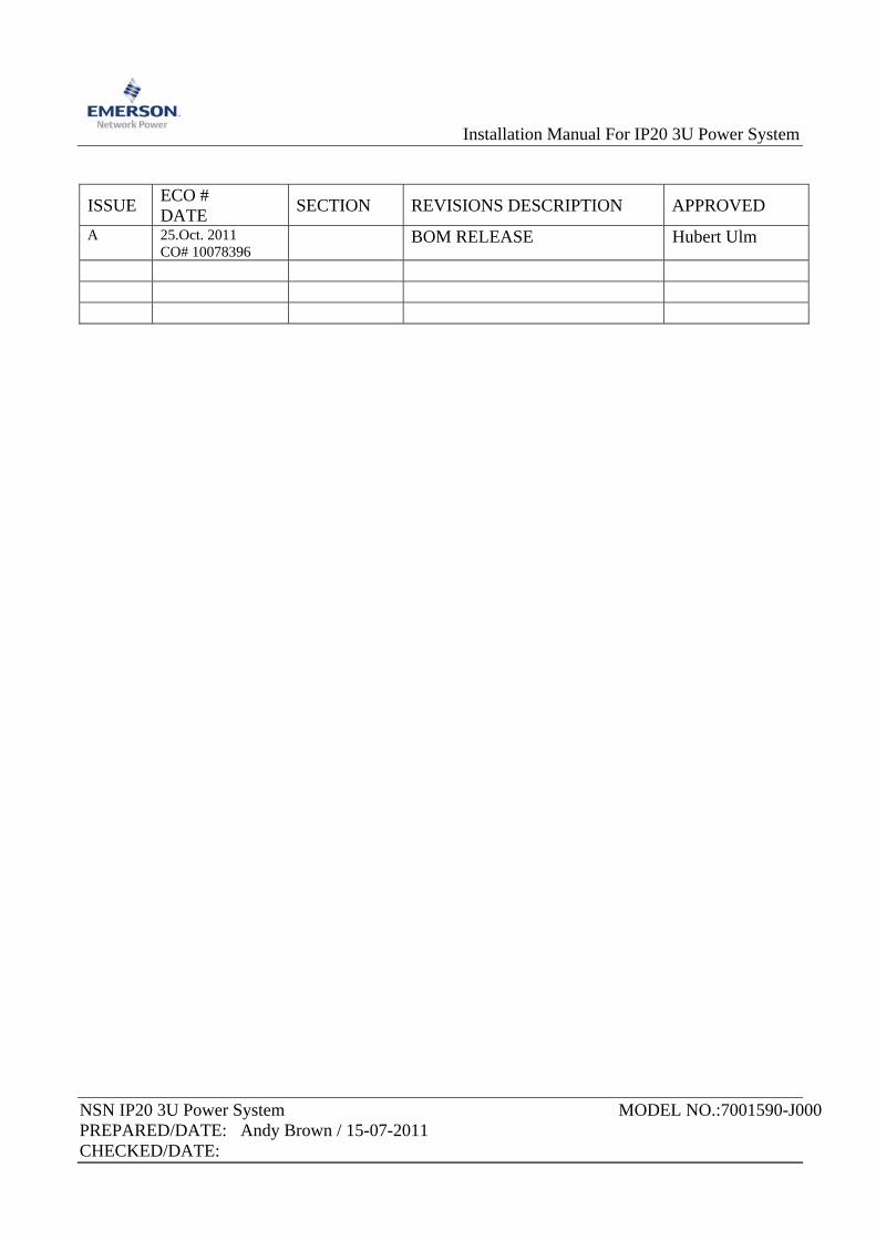
History
Date Version Author Change Note No./Notes 18/05/2010 01 Andy Brown First release 15/07/2011 02 Andy Brown Second release 11/08/2011 18/10/2011
03 A
Markus Grünwald Daniel Kreuzer
Add customer feedback Changed PSA Alarm Table
IP20 3U Power System Installation Manual
Table of contents 5
Table of contents
History ........................................................................................................ 4 Table of contents ........................................................................................ 5 List of figures .............................................................................................. 7 List of tables ............................................................................................... 9 List of terms .............................................................................................. 10 Preface ..................................................................................................... 11 Quick reference step guide ...................................................................... 13
Step description ........................................................................................ 13 Chapter 1 Product Introduction .............................................................. 14
1.1 General Description ............................................................................... 14 1.2 Specification .......................................................................................... 14 1.3 Properties .............................................................................................. 18 1.4 The Power Sub-rack Assembly (PSA) ................................................... 21 1.5 The Rectifier .......................................................................................... 25 1.6 The System control unit (SCU) .............................................................. 28 1.7 The additional Low voltage disconnect unit LVDU ................................ 29 1.8 The optional Surge Suppression Unit .................................................... 30
Chapter 2 Preparation ............................................................................ 31 2.1 Safety Summary .................................................................................... 31 2.2 Installation site ....................................................................................... 33 2.3 Installation tools and test equipments .................................................... 33 2.4 Check list of the IP20 3U Power System ............................................... 34
Chapter 3 Hardware Installation ............................................................. 39 3.1 Remove the unit from the packaging ..................................................... 40 3.2 Remove the lid from the system ............................................................ 41 3.3 Configure the terminal blocks ................................................................ 44 3.3.1 Configure the AC terminal blocks .......................................................... 44 3.3.2 Configure the DC terminal blocks and breakers .................................... 49 Installing the system modules .................................................................. 54 4.1 Installation of the rectifiers ..................................................................... 54 4.2 Removal of the SCU .............................................................................. 59 4.3 Installation of the SCU ........................................................................... 62 4.4 Installation of the additional Load and LVD unit .................................... 63 4.5 Installation of the surge protection device ............................................. 67
Connect the cables .................................................................................. 69 5.1 Connect the AC cables .......................................................................... 70 5.1.1 Earth connection - Connect the AC Earth cable .................................... 71 5.1.2 Earth connection - Connect the system earth ........................................ 72
IP20 3U Power System Installation Manual
Table of contents 6
IP20 3U Power System Installation Manual
5.1.3 Earth connection – Output earth link ..................................................... 73 5.1.4 Connect the AC Live cable(s) ................................................................ 74 5.2 Connect the DC LOAD cables ............................................................... 76 5.2.1 Connect the DC LOAD-1 cables ............................................................ 76 5.2.2 Connect the DC LOAD-2 cables ............................................................ 77 5.3 Connect the DC Battery cables ............................................................. 78
Final system Assembly ............................................................................ 79 6.1 Cable management ............................................................................... 79 The final system assembly ....................................................................... 80
List of figures 7
List of figures
Figure 1 Output power-derating characteristic Figure 2 The schematic of the IP20 3U Power System Figure 3 General view of the IP20 3U Power System Figure 4 Rear view of the IP20 Figure 5 The PSA sub-rack Figure 6 The PSA sub-rack without the casing lid Figure 7 Identifying the system components Figure 8 The IP20 rectifier Figure 9 The rectifier communication cable Figure 10 The SCU unit Figure 11 The optional LVD unit that can be fitted to the PSA Figure 12 The Surge suppression unit that can be fitted to the PSA Figure 13 Product tree Figure 14 The PSA when delivered before the installation Figure 15 Cutting the cable ties that secure the AC cables Figure 16 The screw positions on the PSA Figure 17 Lifting and removing the lid of the system Figure 18 The location of the electrical terminations within the chassis Figure 19 The AC cable connection chart Figure 20 Schematic diag of AC connection without the SPD 1Φ Figure 21 AC terminal block configuration – 1Φ Figure 22 Schematic diagram of AC connection without the SPD – 3∆ Figure 23 AC terminal block configuration – 3∆ Figure 24 Schematic diag of AC connection without the SPD 3Y Figure 25 AC terminal block configuration – 3Yconnection Figure 26 Breaker switch linking bar Figure 27 Standard DC connections NO linking bar’s or bridges in place Figure 28 Adding the bridging component to the load circuit breakers Figure 29 Adding the switch linking to the load circuit breakers Figure 30 Breaker bridge component in place and switch links fitted Figure 31 Fitting CB3/CB4 breaker switch linking bar Figure 32 System ready to accept the rectifier units Figure 33 Putting the rectifier into the first slot of the chassis Figure 34 DC connections of the rectifier Figure 35 The first rectifier fully engaged with the system Figure 36 The system fully populated with rectifiers Figure 37 AC cables connected to the rectifiers in the rack Figure 38 AC cables and signal cables connected to the rectifiers in the rack Figure 39 Placing the temperature probe
IP20 3U Power System Installation Manual
List of figures 8
IP20 3U Power System Installation Manual
Figure 40 Loosening the SCU mounting screws Figure 41 SCU withdrawn from the system chassis Figure 42 Removal of the SCU connectors Figure 43 Releasing the Alarm signal connector Figure 44 SCU rear panel detail Figure 45 Removal of the Load-2 blank panel Figure 46 Placement of the Load 2 LVD/Load module into the system Figure 47 Correct mechanical placement of the Load 2 LVD/Load unit Figure 48 Tighten the LVD M6 nut electrical connection Figure 49 Cable tie the LVD signal wires to the top of the SCU slot Figure 50 Fitting the Load-2 Load/LVD signal connector to the SCU Figure 51 Fitting the SPD to the DIN rail in the PSA. Figure 52 Wiring the SPD into the AC connections Figure 53 The SPD signal connections and wiring loom Figure 54 The SPD signal connector at the SCU Figure 55 Connecting the AC system earth cable Figure 56 Position of the protective earth bonding stud Figure 57 Position of the 0V dc bus ground connection Figure 58 AC cable connection to the system Figure 59 Load-1 DC cable connection to the system Figure 60 Load-2 DC cable connection to the system Figure 61 Battery DC cable connection to the system Figure 62 Cable tie position Figure 63 Cable exit from the system Figure 64 Refitting the cover to the system Figure 65 The finally assembled system ready for system integration Figure 66 The finally assembled system ready for system integration
List of tables 9
List of tables
Table 1 – Contents of this manual ...................................................................... 11 Table 2 – Symbols in the Installation Manual ...................................................... 12 Table 3 – Reference documents of the IP20 ....................................................... 12 Table 4 – Main specifications of the IP20 3U Power System .............................. 14 Table 5 – Applicable rated input voltage types of the IP20 3U Power System .... 15 Table 6 – Main voltages and the corresponding EAC alarms ............................. 16 Table 7 – Static data of the DC output ................................................................ 17 Table 8 – PSA alarm settings ............................................................................ 23 Table 9 – LEDS on the PDA front panel ............................................................. 24 Table 10 – LEDS on the rectifier front panel ....................................................... 26 Table 11 – Term and Symbols in this manual ..................................................... 32 Table 12 – Symbols on the IP20 ......................................................................... 32 Table 13 – Delivery contents by IP20 3U Power System .................................... 35 Table 14 – Three typical battery / load cables configurations ............................. 53
IP20 3U Power System Installation Manual
List of terms 10
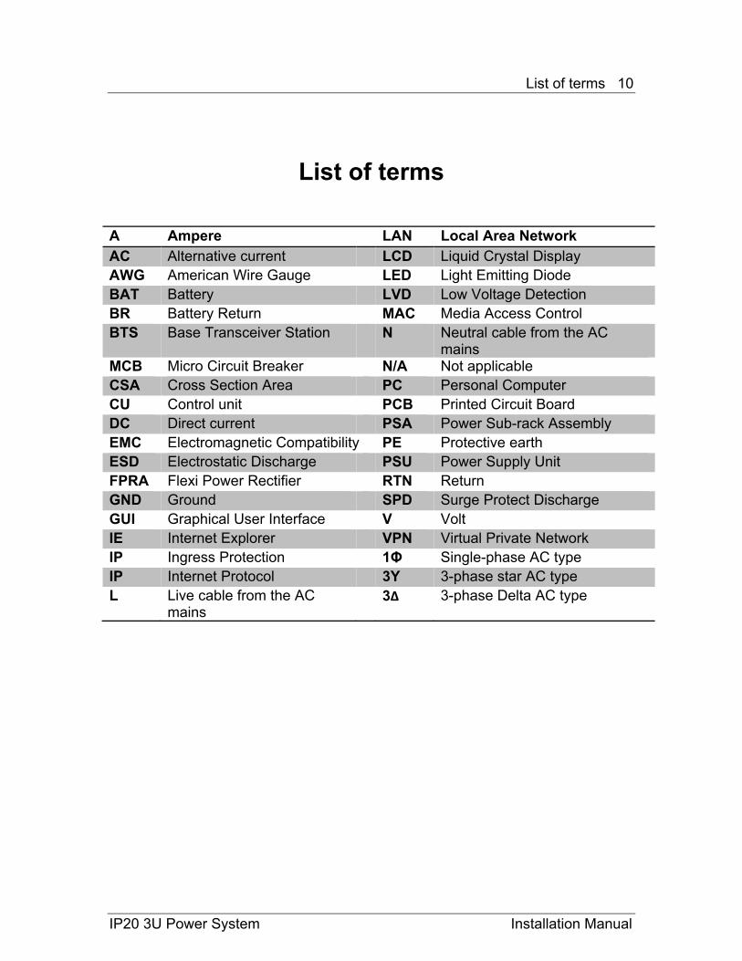
List of terms A Ampere LAN Local Area Network AC Alternative current LCD Liquid Crystal Display AWG American Wire Gauge LED Light Emitting Diode BAT Battery LVD Low Voltage Detection BR Battery Return MAC Media Access Control BTS Base Transceiver Station N Neutral cable from the AC
mains MCB Micro Circuit Breaker N/A Not applicable CSA Cross Section Area PC Personal Computer CU Control unit PCB Printed Circuit Board DC Direct current PSA Power Sub-rack Assembly EMC Electromagnetic Compatibility PE Protective earth ESD Electrostatic Discharge PSU Power Supply Unit FPRA Flexi Power Rectifier RTN Return GND Ground SPD Surge Protect Discharge GUI Graphical User Interface V Volt IE Internet Explorer VPN Virtual Private Network IP Ingress Protection 1Φ Single-phase AC type IP Internet Protocol 3Y 3-phase star AC type L Live cable from the AC
mains 3∆ 3-phase Delta AC type
IP20 3U Power System Installation Manual
List of terms 11
IP20 3U Power System Installation Manual
Preface About this manual
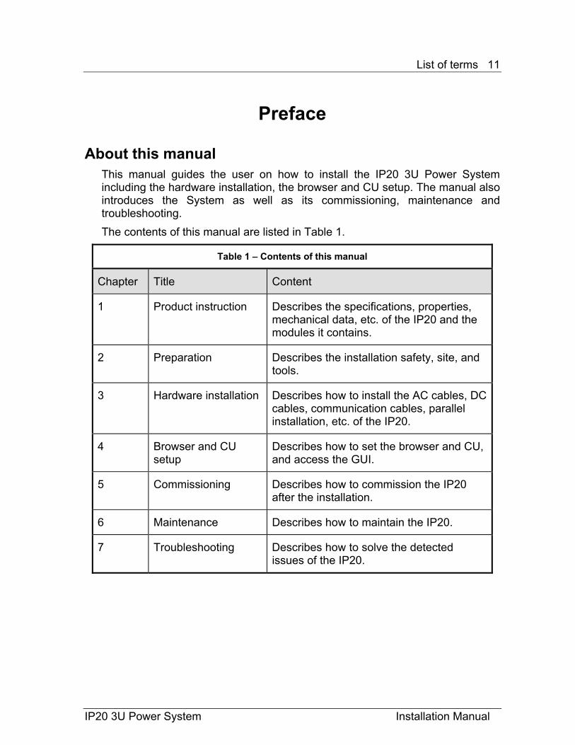
This manual guides the user on how to install the IP20 3U Power System including the hardware installation, the browser and CU setup. The manual also introduces the System as well as its commissioning, maintenance and troubleshooting. The contents of this manual are listed in Table 1.
Table 1 – Contents of this manual
Chapter Title Content
1 Product instruction Describes the specifications, properties, mechanical data, etc. of the IP20 and the modules it contains.
2 Preparation Describes the installation safety, site, and tools.
3 Hardware installation Describes how to install the AC cables, DC cables, communication cables, parallel installation, etc. of the IP20.
4 Browser and CU setup
Describes how to set the browser and CU, and access the GUI.
5 Commissioning Describes how to commission the IP20 after the installation.
6 Maintenance Describes how to maintain the IP20.
7 Troubleshooting Describes how to solve the detected issues of the IP20.
List of terms 12
IP20 3U Power System Installation Manual
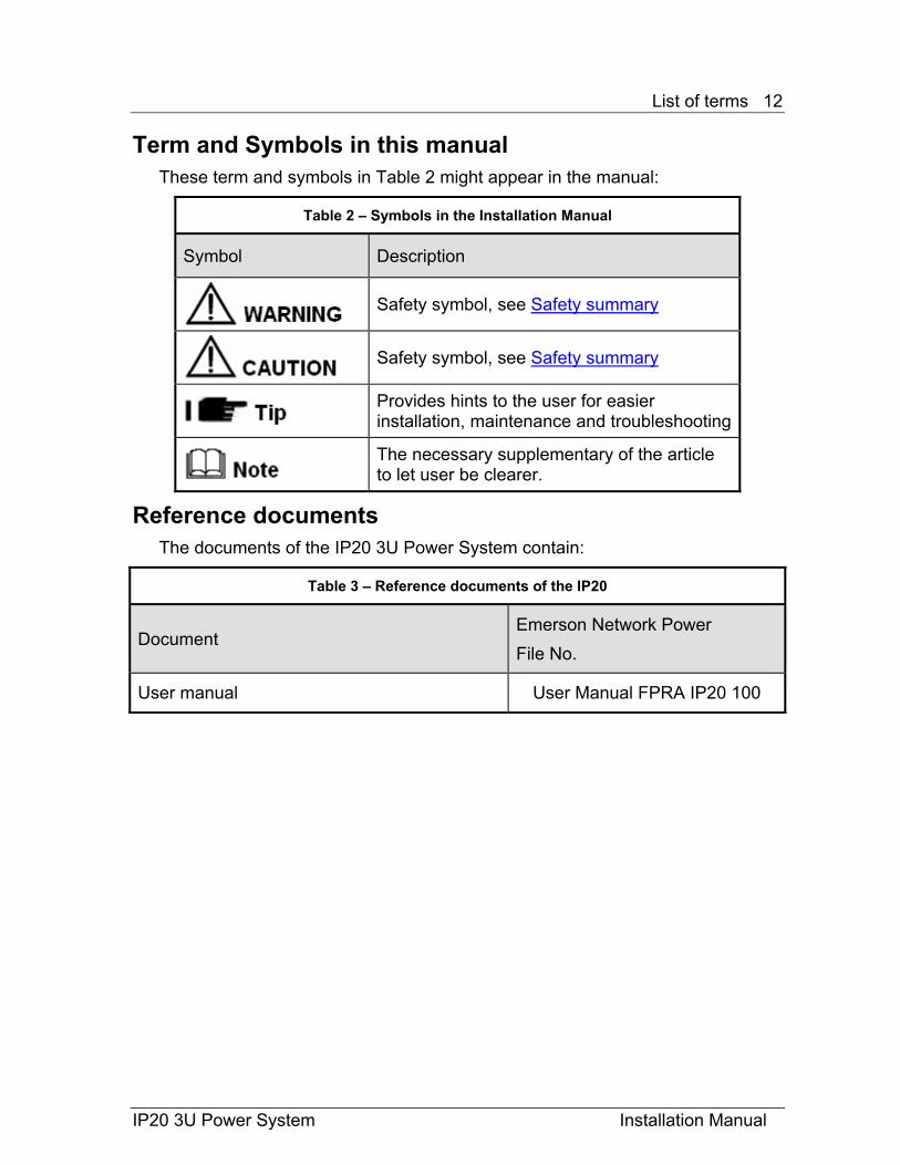
Term and Symbols in this manual These term and symbols in Table 2 might appear in the manual:
Table 2 – Symbols in the Installation Manual
Symbol Description
Safety symbol, see Safety summary
Safety symbol, see Safety summary
Provides hints to the user for easier installation, maintenance and troubleshooting
The necessary supplementary of the article to let user be clearer.
Reference documents The documents of the IP20 3U Power System contain:
Table 3 – Reference documents of the IP20
Document Emerson Network Power File No.
User manual User Manual FPRA IP20 100
List of terms 13
IP20 3U Power System Installation Manual
Quick reference step guide
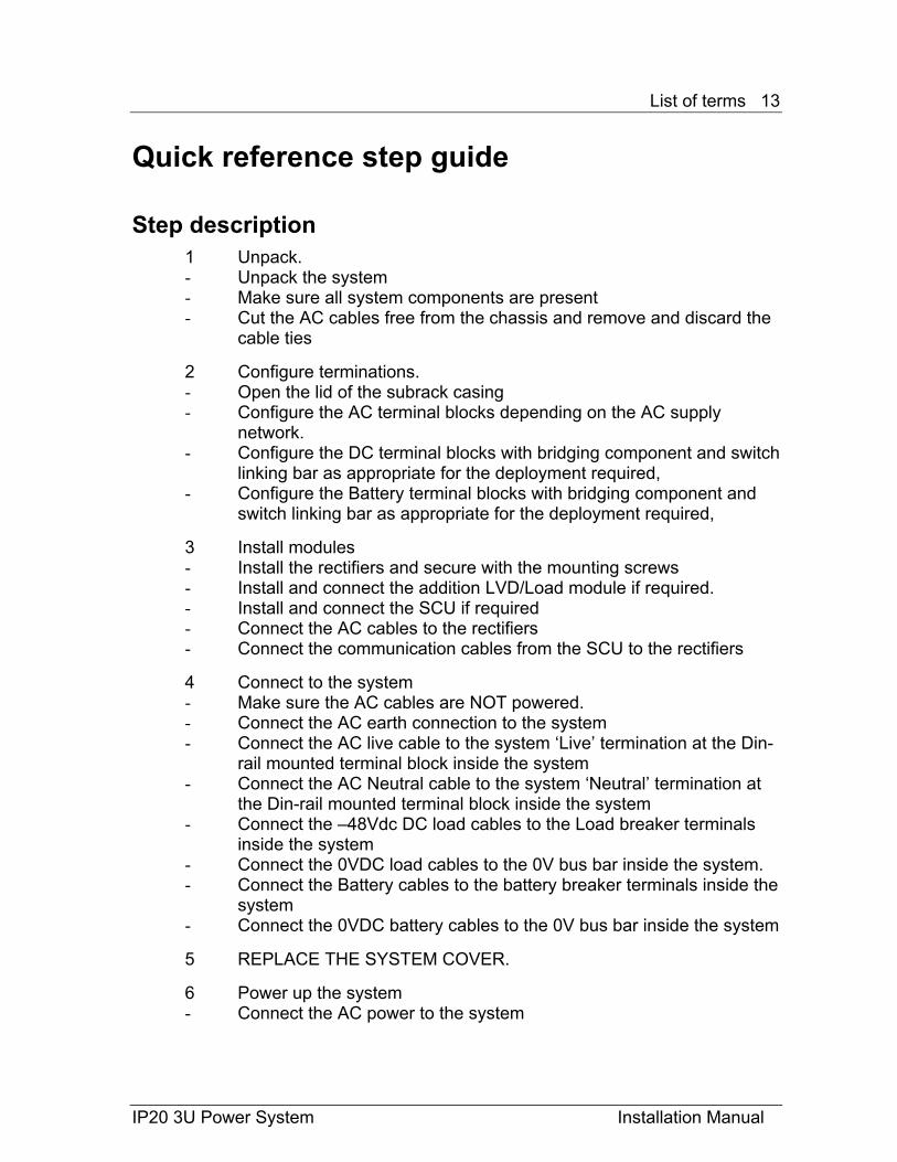
Step description 1 Unpack. - Unpack the system - Make sure all system components are present - Cut the AC cables free from the chassis and remove and discard the
cable ties 2 Configure terminations. - Open the lid of the subrack casing - Configure the AC terminal blocks depending on the AC supply
network. - Configure the DC terminal blocks with bridging component and switch
linking bar as appropriate for the deployment required, - Configure the Battery terminal blocks with bridging component and
switch linking bar as appropriate for the deployment required, 3 Install modules - Install the rectifiers and secure with the mounting screws - Install and connect the addition LVD/Load module if required. - Install and connect the SCU if required - Connect the AC cables to the rectifiers - Connect the communication cables from the SCU to the rectifiers 4 Connect to the system - Make sure the AC cables are NOT powered. - Connect the AC earth connection to the system - Connect the AC live cable to the system ‘Live’ termination at the Din-
rail mounted terminal block inside the system - Connect the AC Neutral cable to the system ‘Neutral’ termination at
the Din-rail mounted terminal block inside the system - Connect the –48Vdc DC load cables to the Load breaker terminals
inside the system - Connect the 0VDC load cables to the 0V bus bar inside the system. - Connect the Battery cables to the battery breaker terminals inside the
system - Connect the 0VDC battery cables to the 0V bus bar inside the system 5 REPLACE THE SYSTEM COVER. 6 Power up the system - Connect the AC power to the system
Product Introduction 14
Chapter 1 Product Introduction 1.1 General Description
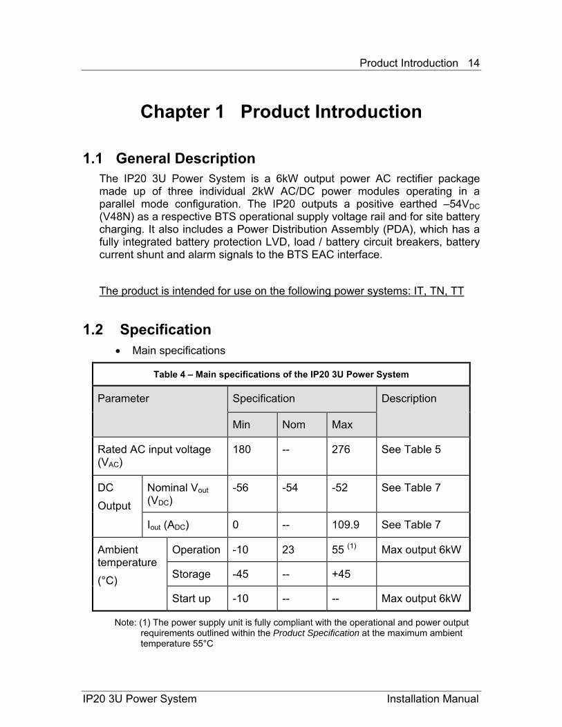
The IP20 3U Power System is a 6kW output power AC rectifier package made up of three individual 2kW AC/DC power modules operating in a parallel mode configuration. The IP20 outputs a positive earthed –54VDC (V48N) as a respective BTS operational supply voltage rail and for site battery charging. It also includes a Power Distribution Assembly (PDA), which has a fully integrated battery protection LVD, load / battery circuit breakers, battery current shunt and alarm signals to the BTS EAC interface. The product is intended for use on the following power systems: IT, TN, TT
1.2 Specification • Main specifications
Table 4 – Main specifications of the IP20 3U Power System
Parameter Specification Description
Min Nom Max
Rated AC input voltage (VAC)
180 -- 276 See Table 5
DC Output
Nominal Vout (VDC)
-56 -54 -52 See Table 7
Iout (ADC) 0 -- 109.9 See Table 7
Ambient temperature (°C)
Operation -10 23 55 (1) Max output 6kW
Storage -45 -- +45
Start up -10 -- -- Max output 6kW
Note: (1) The power supply unit is fully compliant with the operational and power output requirements outlined within the Product Specification at the maximum ambient temperature 55°C
IP20 3U Power System Installation Manual
Product Introduction 15
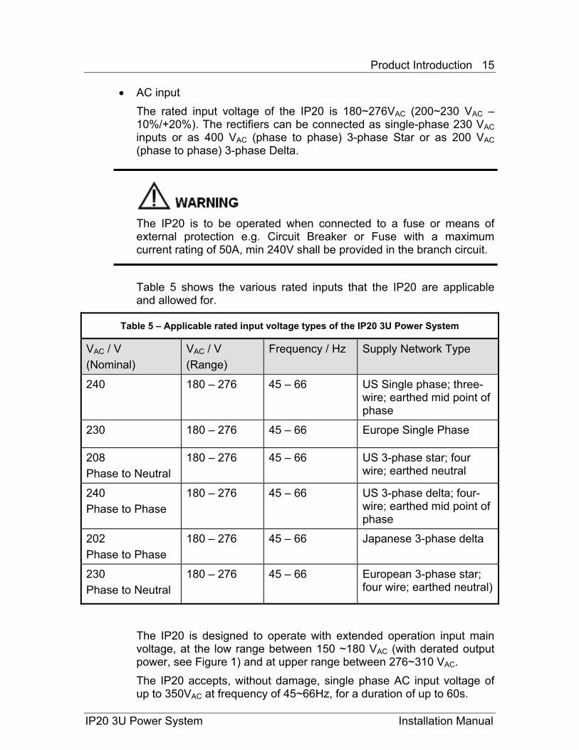
• AC input The rated input voltage of the IP20 is 180~276VAC (200~230 VAC –10%/+20%). The rectifiers can be connected as single-phase 230 VAC inputs or as 400 VAC (phase to phase) 3-phase Star or as 200 VAC (phase to phase) 3-phase Delta.
The IP20 is to be operated when connected to a fuse or means of external protection e.g. Circuit Breaker or Fuse with a maximum current rating of 50A, min 240V shall be provided in the branch circuit. Table 5 shows the various rated inputs that the IP20 are applicable and allowed for.
Table 5 – Applicable rated input voltage types of the IP20 3U Power System
VAC / V (Nominal)
VAC / V (Range)
Frequency / Hz Supply Network Type
240 180 – 276 45 – 66 US Single phase; three-wire; earthed mid point of phase
230 180 – 276 45 – 66 Europe Single Phase
208 Phase to Neutral
180 – 276 45 – 66 US 3-phase star; four wire; earthed neutral
240 Phase to Phase
180 – 276 45 – 66 US 3-phase delta; four-wire; earthed mid point of phase
202 Phase to Phase
180 – 276
45 – 66 Japanese 3-phase delta
230 Phase to Neutral
180 – 276
45 – 66 European 3-phase star; four wire; earthed neutral)
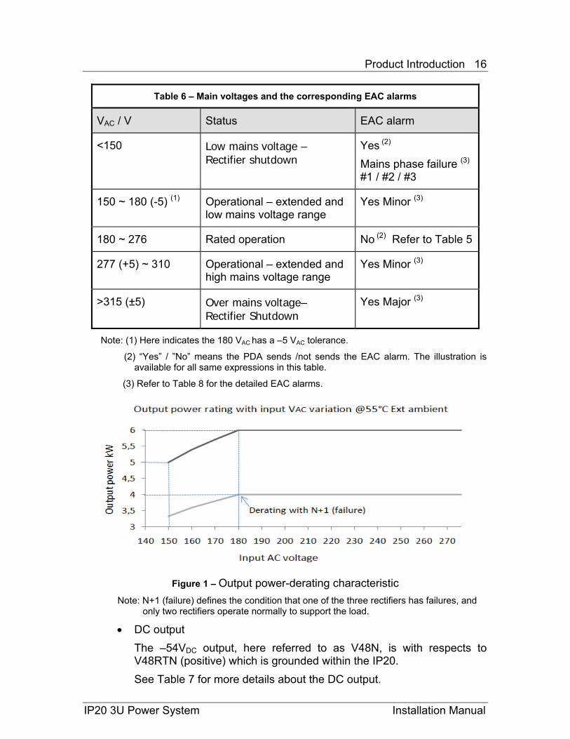
The IP20 is designed to operate with extended operation input main voltage, at the low range between 150 ~180 VAC (with derated output power, see Figure 1) and at upper range between 276~310 VAC. The IP20 accepts, without damage, single phase AC input voltage of up to 350VAC at frequency of 45~66Hz, for a duration of up to 60s.
IP20 3U Power System Installation Manual
Product Introduction 16
Table 6 – Main voltages and the corresponding EAC alarms
VAC / V Status EAC alarm
<150 Low mains voltage – Rectifier shutdown
Yes (2) Mains phase failure (3)
#1 / #2 / #3
150 ~ 180 (-5) (1) Operational – extended and low mains voltage range
Yes Minor (3)
180 ~ 276 Rated operation No (2) Refer to Table 5
277 (+5) ~ 310 Operational – extended and high mains voltage range
Yes Minor (3)
>315 (±5) Over mains voltage– Rectifier Shutdown
Yes Major (3)
Note: (1) Here indicates the 180 VAC has a –5 VAC tolerance.
(2) “Yes” / ”No” means the PDA sends /not sends the EAC alarm. The illustration is available for all same expressions in this table.
(3) Refer to Table 8 for the detailed EAC alarms.
Figure 1 – Output power-derating characteristic
Note: N+1 (failure) defines the condition that one of the three rectifiers has failures, and only two rectifiers operate normally to support the load.
• DC output The –54VDC output, here referred to as V48N, is with respects to V48RTN (positive) which is grounded within the IP20. See Table 7 for more details about the DC output.
IP20 3U Power System Installation Manual
Product Introduction 17
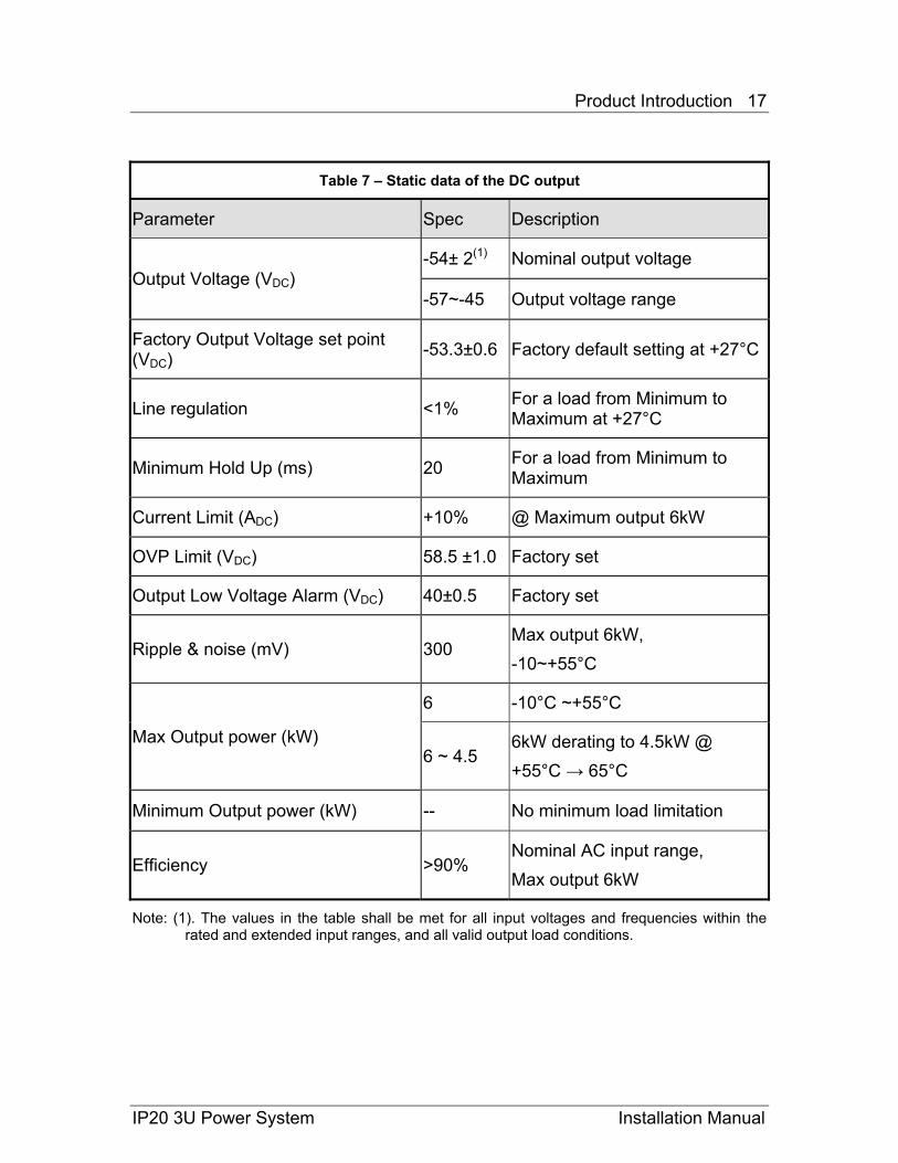
Table 7 – Static data of the DC output
Parameter Spec Description
Output Voltage (VDC) -54± 2(1) Nominal output voltage
-57~-45 Output voltage range
Factory Output Voltage set point (VDC) -53.3±0.6 Factory default setting at +27°C
Line regulation <1% For a load from Minimum to Maximum at +27°C
Minimum Hold Up (ms) 20 For a load from Minimum to Maximum
Current Limit (ADC) +10% @ Maximum output 6kW
OVP Limit (VDC) 58.5 ±1.0 Factory set
Output Low Voltage Alarm (VDC) 40±0.5 Factory set
Ripple & noise (mV) 300 Max output 6kW, -10~+55°C
Max Output power (kW)
6 -10°C ~+55°C
6 ~ 4.5 6kW derating to 4.5kW @ +55°C → 65°C
Minimum Output power (kW) -- No minimum load limitation
Efficiency >90% Nominal AC input range, Max output 6kW
Note: (1). The values in the table shall be met for all input voltages and frequencies within the rated and extended input ranges, and all valid output load conditions.
IP20 3U Power System Installation Manual
Product Introduction 18
IP20 3U Power System Installation Manual
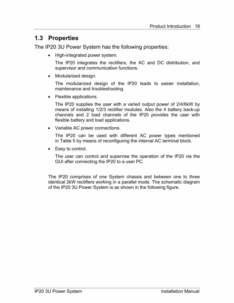
1.3 Properties The IP20 3U Power System has the following properties:
• High-integrated power system. The IP20 integrates the rectifiers, the AC and DC distribution, and supervisor and communication functions.
• Modularized design. The modularized design of the IP20 leads to easier installation, maintenance and troubleshooting.
• Flexible applications. The IP20 supplies the user with a varied output power of 2/4/6kW by means of installing 1/2/3 rectifier modules. Also the 4 battery back-up channels and 2 load channels of the IP20 provides the user with flexible battery and load applications.
• Variable AC power connections. The IP20 can be used with different AC power types mentioned in Table 5 by means of reconfiguring the internal AC terminal block.
• Easy to control. The user can control and supervise the operation of the IP20 via the GUI after connecting the IP20 to a user PC.
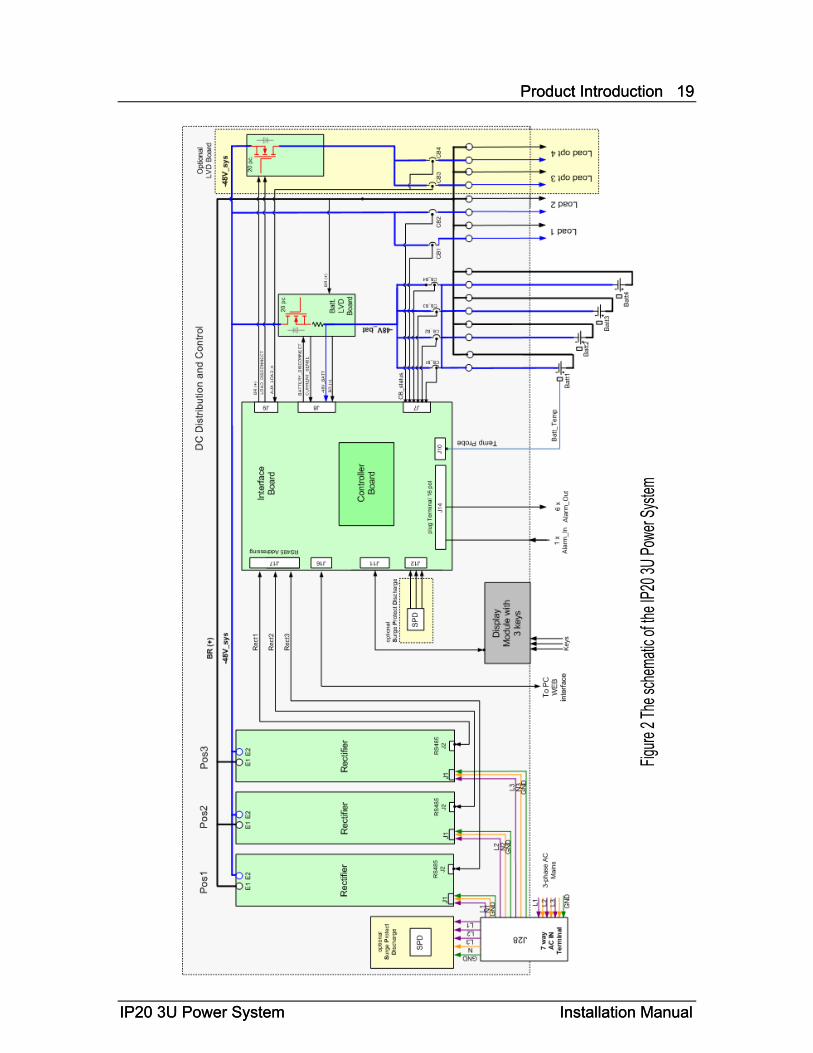
The IP20 comprises of one System chassis and between one to three identical 2kW rectifiers working in a parallel mode. The schematic diagram of the IP20 3U Power System is as shown in the following figure.
Product Introduction 19
IP20 3U Power System Installation Manual
Product Introduction 19
IP20 3U Power System Installation Manual
Product Introduction 20
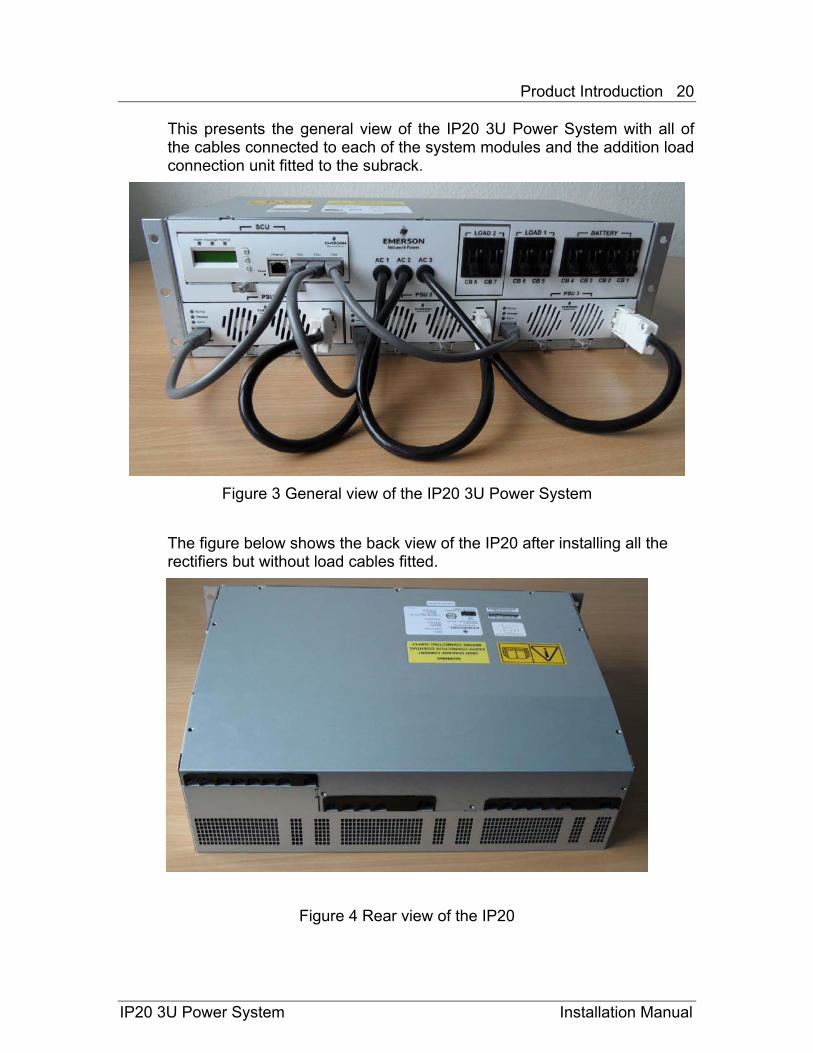
This presents the general view of the IP20 3U Power System with all of the cables connected to each of the system modules and the addition load connection unit fitted to the subrack.
Figure 3 General view of the IP20 3U Power System
The figure below shows the back view of the IP20 after installing all the rectifiers but without load cables fitted.
Figure 4 Rear view of the IP20
IP20 3U Power System Installation Manual
Product Introduction 21
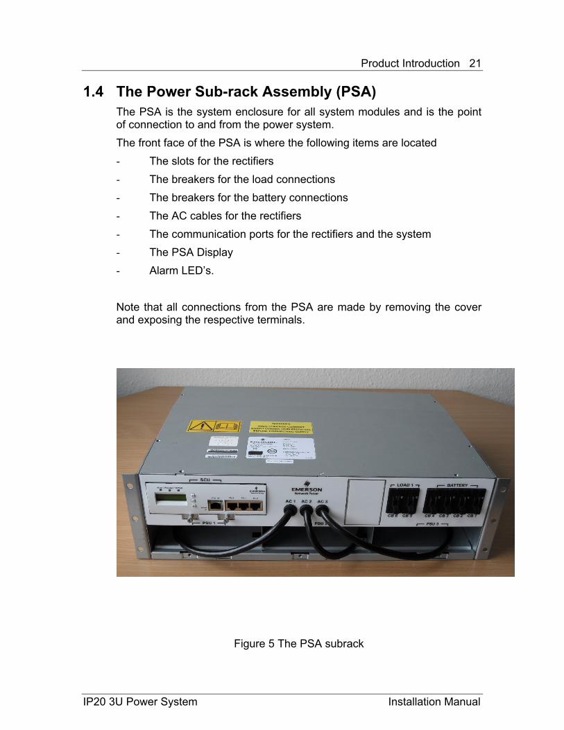
1.4 The Power Sub-rack Assembly (PSA) The PSA is the system enclosure for all system modules and is the point of connection to and from the power system. The front face of the PSA is where the following items are located - The slots for the rectifiers - The breakers for the load connections - The breakers for the battery connections - The AC cables for the rectifiers - The communication ports for the rectifiers and the system - The PSA Display - Alarm LED’s. Note that all connections from the PSA are made by removing the cover and exposing the respective terminals.
Figure 5 The PSA subrack
IP20 3U Power System Installation Manual
Product Introduction 22
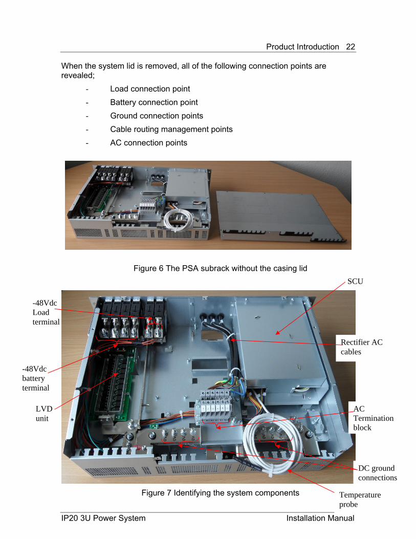
When the system lid is removed, all of the following connection points are revealed;
- Load connection point - Battery connection point - Ground connection points - Cable routing management points - AC connection points
Figure 6 The PSA subrack without the casing lid SCU
-48Vdc Load terminal
Rectifier AC cables
LVD unit
-48Vdc battery terminal
AC Termination block
Figure 7 Identifying the system components
IP20 3U Power System Installation Manual
Temperature probe
DC ground connections

Product Introduction 23
Table 8 – PSA alarm settings
EAC alarm Description
Alarm 1 Enables the Signal on Alarm Pin 1
Alarm 2 Enables the Signal on Alarm Pin 2
Alarm 3 Enables the Signal on Alarm Pin 3
Alarm 4 Enables the Signal on Alarm Pin 4
Alarm 5 Enables the Signal on Alarm Pin 5
Alarm 6 Enables the Signal on Alarm Pin 6
• Network connection based on LAN. The PDA can be connected to a user PC via the internal RJ45 interface. The user can monitor the whole system via a web-based GUI. Each possible Alarm of the System (including Control Unit and Rectifier) can be mapped to one of the Alarm Out Pins on the backside of the Control Unit. Multiple Alarms can be mapped to a single pin. Combinations of alarms can be mapped to a single pin. For a “how to change” the mapping of the alarms please put a reference to the User Manual (section tbd)
IP20 3U Power System Installation Manual
Product Introduction 24
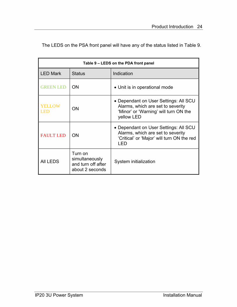
The LEDS on the PSA front panel will have any of the status listed in Table 9.
Table 9 – LEDS on the PDA front panel
LED Mark Status Indication
GREEN LED ON • Unit is in operational mode
YELLOW LED ON
• Dependant on User Settings: All SCU Alarms, which are set to severity ‘Minor’ or ‘Warning’ will turn ON the yellow LED
FAULT LED ON
• Dependant on User Settings: All SCU Alarms, which are set to severity ‘Critical’ or ‘Major’ will turn ON the red LED
All LEDS
Turn on simultaneously and turn off after about 2 seconds
System initialization
IP20 3U Power System Installation Manual
Product Introduction 25
1.5 The Rectifier The IP20 supports the operation of up to three rectifiers in parallel. Each rectifier is an AC/DC module, which meets the specifications listed in Table 5 and Table 7. The rectifier has the following properties:
• High efficiency. The rectifier has an over 90% efficiency at the nominal AC input voltage.
• Over current protection. The rectifier shuts down once an over current is detected, and recovers automatically when the fault is no longer present.
• Over voltage protection. The rectifier shuts down once an over voltage is detected for the first time, and recovers automatically when the fault is no longer present. If the over voltage is detected for the second time, the rectifier will shuts down for ever until the AC power supply re-powers up to restart the rectifier.
• Monitoring function. The rectifier monitors different parameters such as input voltage, output voltage, etc., and sends out a corresponding alarm signal in case it detects a fault.
• Self-cooling function. Each rectifier has an internal fan for cooling.
• RS485 interface. The rectifier can be connected to the PDA via the internal RS485 interface. In this way, user can monitor and control three rectifiers via the GUI.
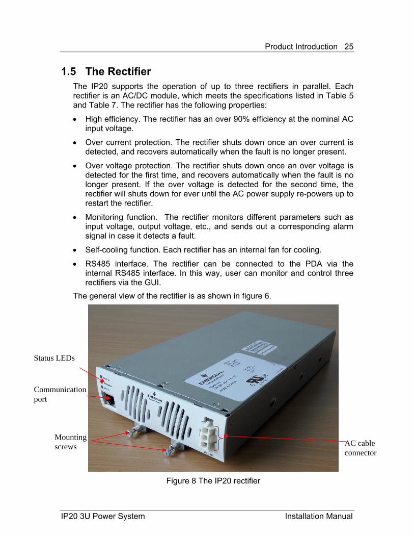
The general view of the rectifier is as shown in figure 6.
Figure 8 The IP20 rectifier
Status LEDs
Communication port
AC cable connector
Mounting screws
IP20 3U Power System Installation Manual
Product Introduction 26
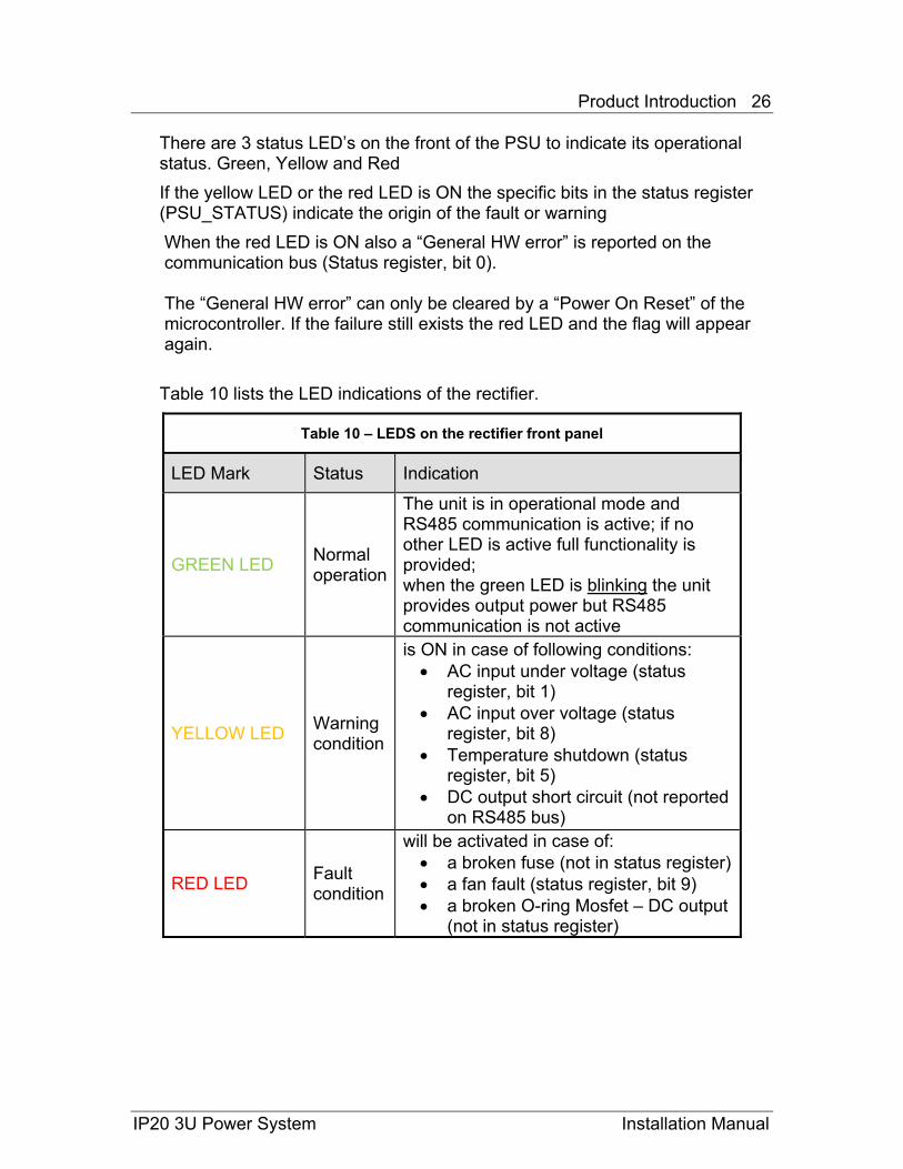
There are 3 status LED’s on the front of the PSU to indicate its operational status. Green, Yellow and Red If the yellow LED or the red LED is ON the specific bits in the status register (PSU_STATUS) indicate the origin of the fault or warning When the red LED is ON also a “General HW error” is reported on the communication bus (Status register, bit 0). The “General HW error” can only be cleared by a “Power On Reset” of the microcontroller. If the failure still exists the red LED and the flag will appear again. Table 10 lists the LED indications of the rectifier.
Table 10 – LEDS on the rectifier front panel
LED Mark Status Indication
GREEN LED Normal operation
The unit is in operational mode and RS485 communication is active; if no other LED is active full functionality is provided; when the green LED is blinking the unit provides output power but RS485 communication is not active
YELLOW LED Warning condition
is ON in case of following conditions: • AC input under voltage (status
register, bit 1) • AC input over voltage (status
register, bit 8) • Temperature shutdown (status
register, bit 5) • DC output short circuit (not reported
on RS485 bus)
RED LED Fault condition
will be activated in case of: • a broken fuse (not in status register)• a fan fault (status register, bit 9) • a broken O-ring Mosfet – DC output
(not in status register)
IP20 3U Power System Installation Manual
Product Introduction 27
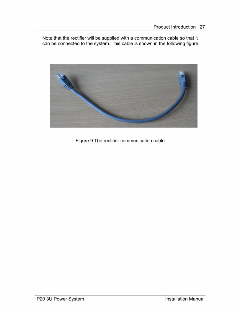
Note that the rectifier will be supplied with a communication cable so that it can be connected to the system. This cable is shown in the following figure
Figure 9 The rectifier communication cable
IP20 3U Power System Installation Manual
Product Introduction 28
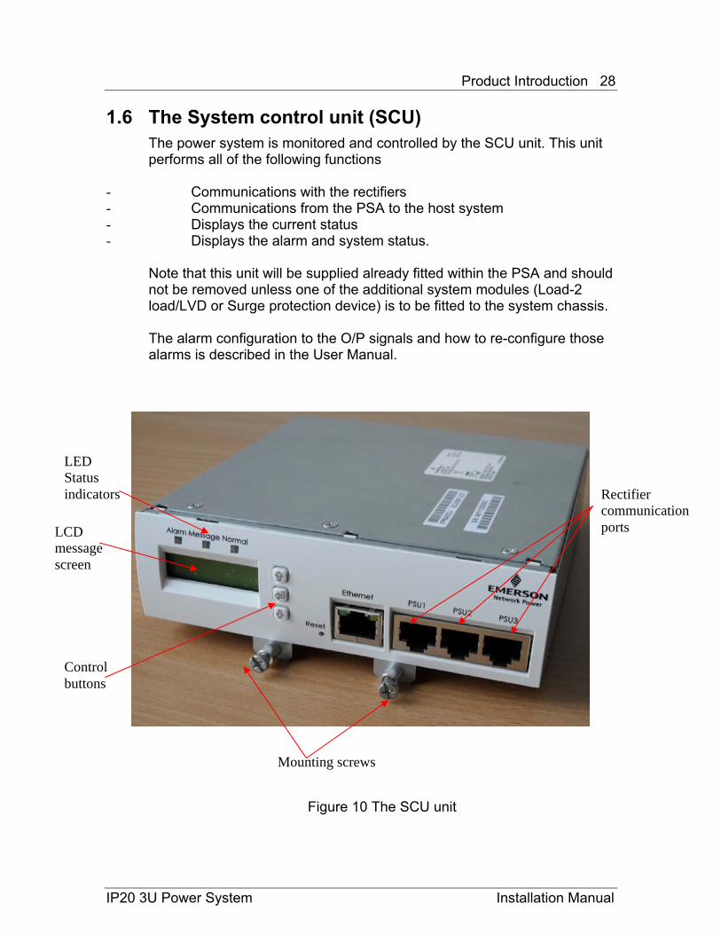
1.6 The System control unit (SCU) The power system is monitored and controlled by the SCU unit. This unit performs all of the following functions
- Communications with the rectifiers - Communications from the PSA to the host system - Displays the current status - Displays the alarm and system status.
Note that this unit will be supplied already fitted within the PSA and should not be removed unless one of the additional system modules (Load-2 load/LVD or Surge protection device) is to be fitted to the system chassis. The alarm configuration to the O/P signals and how to re-configure those alarms is described in the User Manual.
LCD message screen
LED Status indicators Rectifier
communication ports
Control buttons
Mounting screws
Figure 10 The SCU unit
IP20 3U Power System Installation Manual
Product Introduction 29
.
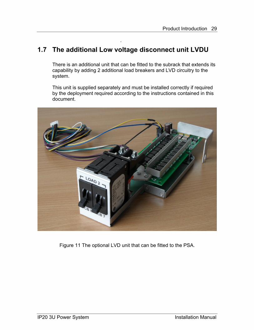
1.7 The additional Low voltage disconnect unit LVDU There is an additional unit that can be fitted to the subrack that extends its capability by adding 2 additional load breakers and LVD circuitry to the system. This unit is supplied separately and must be installed correctly if required by the deployment required according to the instructions contained in this document.
Figure 11 The optional LVD unit that can be fitted to the PSA.
IP20 3U Power System Installation Manual

Product Introduction 30
1.8 The optional Surge Suppression Unit
There is an additional surge suppression unit that can be fitted to the sub-rack which extends the systems surge immunity capability. This is required where the mains AC feed is particularly un-predictable and has transients on it.
This unit is supplied separately and must be installed correctly if required by the deployment required according to the instructions contained in this document.
Figure 12 The Surge suppression unit that can be fitted to the PSA.
IP20 3U Power System Installation Manual
Preparation 31
IP20 3U Power System Installation Manual
Chapter 2 Preparation 2.1 Safety Summary
2.1.1 Injury and product damage precautions The following precautions must be observed during all phases of servicing the product, such as installation, maintenance or configuration. Any omission of the precautions might cause injury and/or product damage. • Do not service the product during a thunder / lightning storm to avoid
electric shock.
• Turn off the AC power source when accessing the AC cables or the SPD to avoid electric shock.
• Make sure the product is well grounded before servicing the product to avoid electric shock.
• Do not install the product in an explosive atmosphere to avoid injury or fire hazard.
• Do not service the product if the environment cannot meet the requirements defined in the product specification.
• Do not place the product in an unstable rack, to avoid the product damage in case of a fall.
• Do not open the restricted area by unqualified personnel, to avoid damage to the product.
• After unpacking, do not start the installation if you suspect any product damage caused by shipment.
• Pay attention to the specific warning/caution terms and symbols in this manual.
• Equipment is intended for installation in restricted access locations
• Requirements for protection in service access areas and restricted access areas apply
• Equipment is intended for operation at altitudes up to 3000m above sea level
2.1.2 Safety Term and Symbols These term and symbols listed in Table 11 may appear in this manual:
Preparation 32
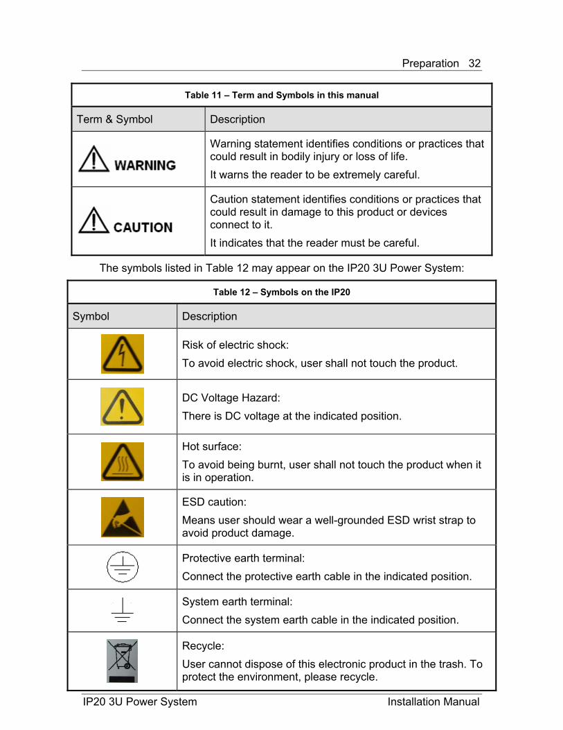
Table 11 – Term and Symbols in this manual
Term & Symbol Description
Warning statement identifies conditions or practices that could result in bodily injury or loss of life. It warns the reader to be extremely careful.
Caution statement identifies conditions or practices that could result in damage to this product or devices connect to it. It indicates that the reader must be careful.
The symbols listed in Table 12 may appear on the IP20 3U Power System:
Table 12 – Symbols on the IP20
Symbol Description
Risk of electric shock: To avoid electric shock, user shall not touch the product.
DC Voltage Hazard: There is DC voltage at the indicated position.
Hot surface: To avoid being burnt, user shall not touch the product when it is in operation.
ESD caution: Means user should wear a well-grounded ESD wrist strap to avoid product damage.
Protective earth terminal: Connect the protective earth cable in the indicated position.
System earth terminal: Connect the system earth cable in the indicated position.
Recycle: User cannot dispose of this electronic product in the trash. To protect the environment, please recycle.
IP20 3U Power System Installation Manual
Preparation 33
IP20 3U Power System Installation Manual
2.2 Installation site To ensure normal operation and long service life of the product, install it in an environment that meets the following requirements:
• Temperature The IP20 should be used and maintained in the temperature that defined in Table 4.
• Cleanness Dust is a hazard to the operation to the device. The dust accumulated on the chassis can be absorbed by static electricity and result in poor contact of metal connectors. This not only shortens the service life of your device but may also cause communication failures. Besides dust, the harmful gases, containing salts, acids and sulfides, can accelerate the corrosion and aging of metals.
• Ventilation Each rectifier has an integrated fan for cooling. The airflow is from the rear to the front of the rectifier unit. Consideration should be given to the amount of clearance necessary to ensure IP20 cooling when configured within cabinets.
2.3 Installation tools and test equipments Tool kit:
ESD wrist strap and cable TORX screwdriver set: T10, Flat screwdriver Cross screwdriver (6xP1 Phillips) Nut spinner for M6 and M5 nut Side cutters Lint-free swab or wipe and 99% alcohol for cleaning optical connectors Cable ties for routing cables Flashlight, pocket lamp or torch Pliers Wire-stripper
• Test equipments PC (optional) Multi-meter: FLUKE 170 or equivalent DC Current clamp: FLUKE I410 or equivalent
Preparation 34
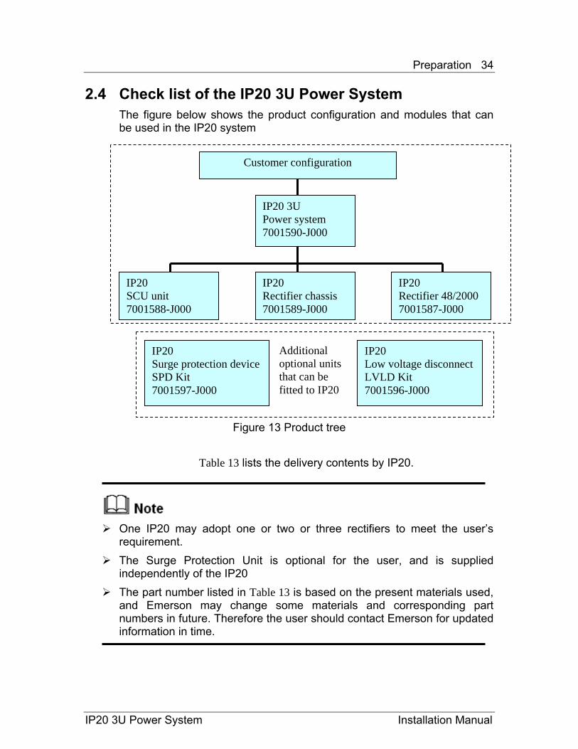
2.4 Check list of the IP20 3U Power System The figure below shows the product configuration and modules that can be used in the IP20 system
Customer configuration
IP20 3U Power system 7001590-J000
IP20 SCU unit 7001588-J000
IP20 Rectifier chassis 7001589-J000
IP20 Rectifier 48/2000 7001587-J000
IP20 Surge protection device SPD Kit 7001597-J000
IP20 Low voltage disconnect LVLD Kit 7001596-J000
Additional optional units that can be fitted to IP20
Figure 13 Product tree
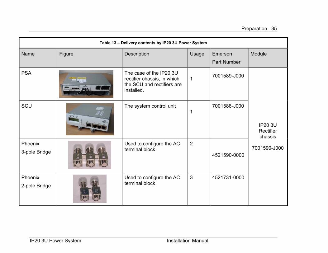
Table 13 lists the delivery contents by IP20.
One IP20 may adopt one or two or three rectifiers to meet the user’s
requirement. The Surge Protection Unit is optional for the user, and is supplied
independently of the IP20 The part number listed in Table 13 is based on the present materials used,
and Emerson may change some materials and corresponding part numbers in future. Therefore the user should contact Emerson for updated information in time.
IP20 3U Power System Installation Manual
Preparation 35
Table 13 – Delivery contents by IP20 3U Power System
Name Figure Description Usage Emerson Part Number
Module
PSA
The case of the IP20 3U rectifier chassis, in which the SCU and rectifiers are installed.
1 7001589-J000
IP20 3U Rectifier chassis
7001590-J000
SCU
The system control unit 1
7001588-J000
Phoenix 3-pole Bridge
Used to configure the AC terminal block
2
4521590-0000
Phoenix 2-pole Bridge
Used to configure the AC terminal block
3 4521731-0000
IP20 3U Power System Installation Manual
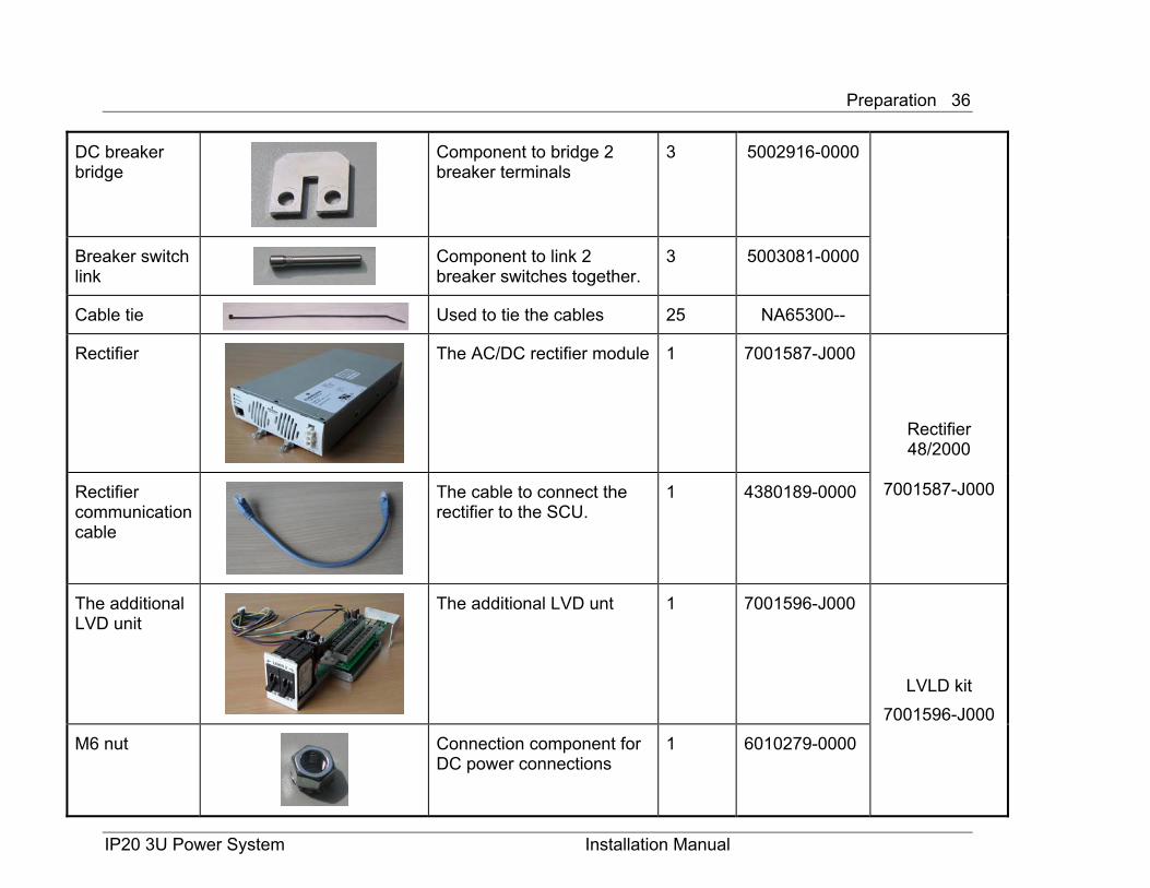
Preparation 36
DC breaker bridge
Component to bridge 2 breaker terminals
3 5002916-0000
Breaker switch link
Component to link 2 breaker switches together.
3 5003081-0000
Cable tie Used to tie the cables 25 NA65300--
Rectifier
The AC/DC rectifier module 1 7001587-J000
Rectifier 48/2000
7001587-J000 Rectifier
communication cable
The cable to connect the rectifier to the SCU.
1 4380189-0000
The additional LVD unit
The additional LVD unt 1 7001596-J000
LVLD kit 7001596-J000
M6 nut
Connection component for DC power connections
1 6010279-0000
IP20 3U Power System Installation Manual
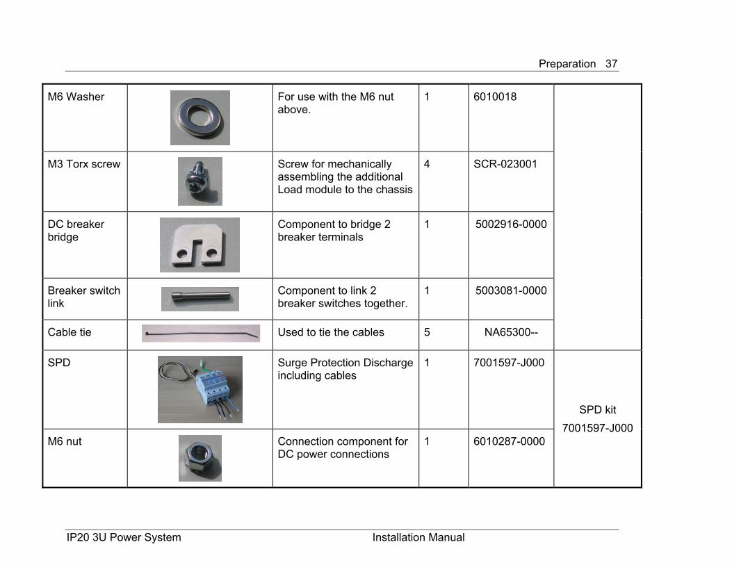
Preparation 37
M6 Washer
For use with the M6 nut above.
1 6010018
M3 Torx screw
Screw for mechanically assembling the additional Load module to the chassis
4 SCR-023001
DC breaker bridge
Component to bridge 2 breaker terminals
1 5002916-0000
Breaker switch link
Component to link 2 breaker switches together.
1 5003081-0000
Cable tie Used to tie the cables 5 NA65300--
SPD
Surge Protection Discharge including cables
1 7001597-J000
SPD kit 7001597-J000
M6 nut
Connection component for DC power connections
1 6010287-0000
IP20 3U Power System Installation Manual
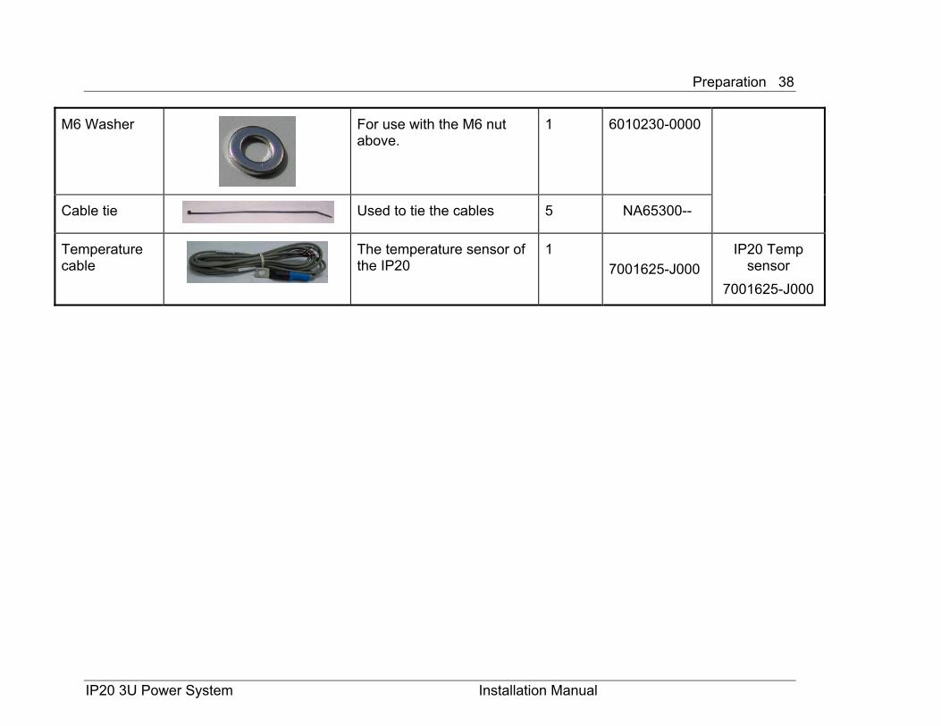
M6 Washer
For use with the M6 nut above.
1 6010230-0000
Cable tie Used to tie the cables 5 NA65300--
Preparation 38
IP20 3U Power System Installation Manual
Temperature cable
The temperature sensor of the IP20
1 7001625-J000
IP20 Temp sensor
7001625-J000
Hardware Installation 39
Chapter 3 Hardware Installation
Before hardware installation, please note:
All the precautions listed in the Safety summary. The installation should be carried out only by qualified personnel and in
accordance with local electrical codes.
The installation sequence summary of the various system modules described below is mandatory for first time installation of the IP20 components. The detailed installation procedure for each module can be found in the appropriate sections further on in this document.
IP20 3U Power System Installation Manual
Hardware Installation 40
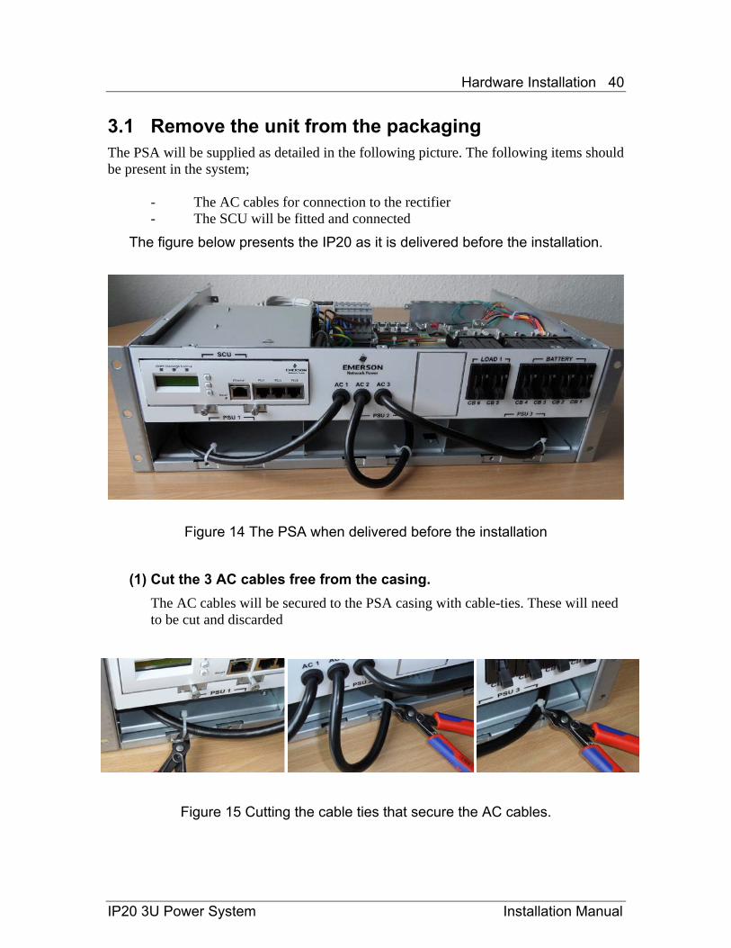
3.1 Remove the unit from the packaging The PSA will be supplied as detailed in the following picture. The following items should be present in the system;
- The AC cables for connection to the rectifier - The SCU will be fitted and connected
The figure below presents the IP20 as it is delivered before the installation.
Figure 14 The PSA when delivered before the installation
(1) Cut the 3 AC cables free from the casing. The AC cables will be secured to the PSA casing with cable-ties. These will need to be cut and discarded
Figure 15 Cutting the cable ties that secure the AC cables.
IP20 3U Power System Installation Manual

Hardware Installation 41
3.2 Remove the lid from the system
(2) Remove the PSA case To access the load and battery connections it will be necessary to remove the casing of the PSA. To do this remove the 10 screws as indicated below. These are P1 Phillips screws. There are 7 screws on the top of the cover and a further 3 on the rear panel of the PSA. Once the screws are removed, remove the cover from the subrack.
Figure 16 The screw positions on the PSA.
Screw locations on the subrack casing
IP20 3U Power System Installation Manual
Hardware Installation 42
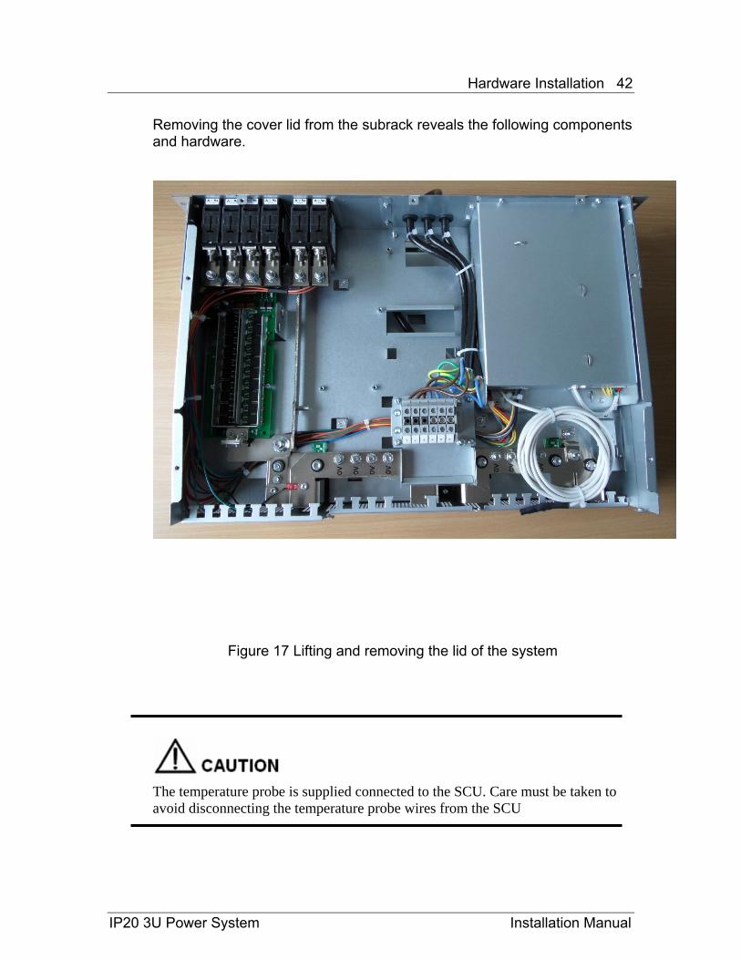
Removing the cover lid from the subrack reveals the following components and hardware.
Figure 17 Lifting and removing the lid of the system
The temperature probe is supplied connected to the SCU. Care must be taken to avoid disconnecting the temperature probe wires from the SCU
IP20 3U Power System Installation Manual
Hardware Installation 43
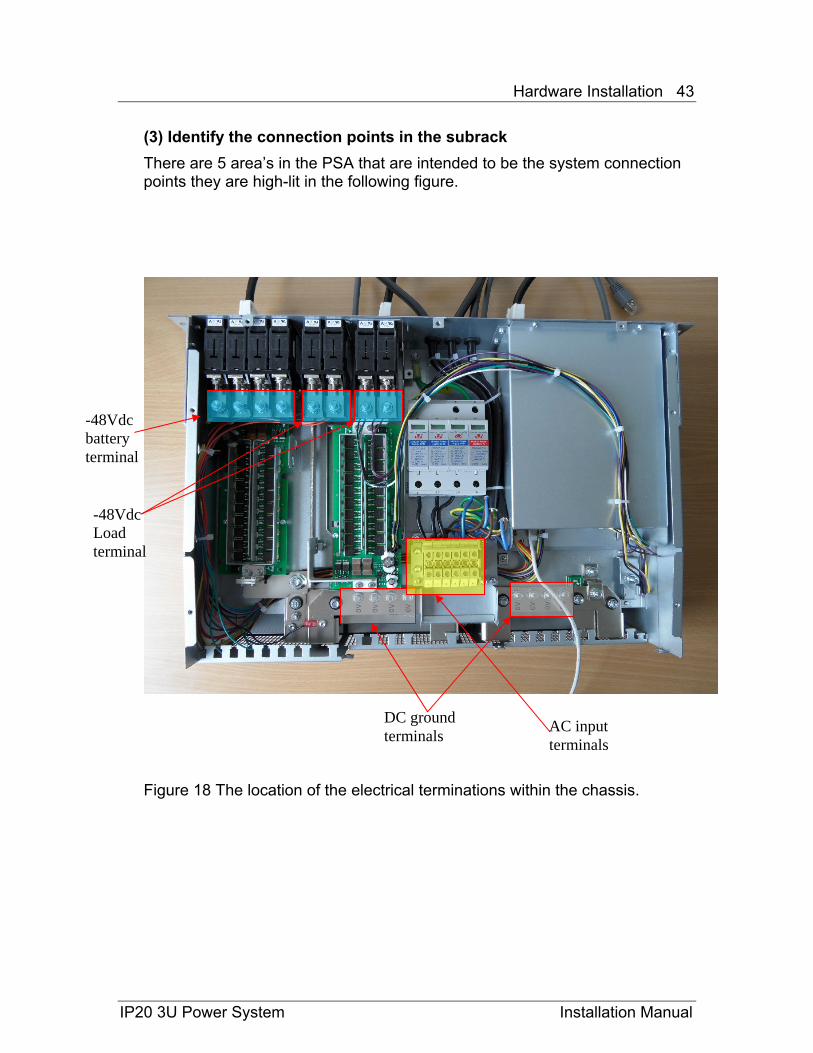
(3) Identify the connection points in the subrack There are 5 area’s in the PSA that are intended to be the system connection points they are high-lit in the following figure.
AC input terminals
DC ground terminals
-48Vdc Load terminal
-48Vdc battery terminal
Figure 18 The location of the electrical terminations within the chassis.
IP20 3U Power System Installation Manual

Hardware Installation 44
IP20 3U Power System Installation Manual
3.3 Configure the terminal blocks The terminal blocks for both the AC and DC terminations must be configured to suit the demands of the deployment site.
3.3.1 Configure the AC terminal blocks
Verify the AC power system types in field, and make sure the corresponding bridge configuration is used.
The AC terminal block has been already configured for 3-phase star AC mains before the shipment. Therefore the user has to change the AC terminal block configuration if required referring to the actual AC type in field.
Insert the Phoenix bridges and screws (provided as accessories) to the corresponding slots on top of the AC terminal block referring to the AC CABLE CONNECTION CHART located on the chassis (and reproduced in Figure). Secure the screws with a flat screwdriver, tightening to 0.8Nm.
Figure 19 The AC cable connection chart
Hardware Installation 45
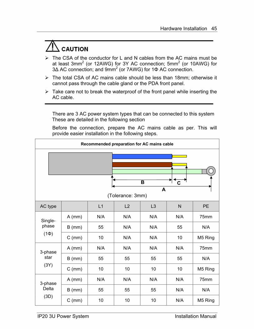
The CSA of the conductor for L and N cables from the AC mains must be
at least 3mm2 (or 12AWG) for 3Y AC connection; 5mm2 (or 10AWG) for 3∆ AC connection; and 9mm2 (or 7AWG) for 1Φ AC connection.
The total CSA of AC mains cable should be less than 18mm; otherwise it cannot pass through the cable gland or the PDA front panel.
Take care not to break the waterproof of the front panel while inserting the AC cable.
There are 3 AC power system types that can be connected to this system These are detailed in the following section Before the connection, prepare the AC mains cable as per. This will provide easier installation in the following steps.
Recommended preparation for AC mains cable
(Tolerance: 3mm)
AC type L1 L2 L3 N PE
Single-phase
(1Φ)
A (mm) N/A N/A N/A N/A 75mm
B (mm) 55 N/A N/A 55 N/A
C (mm) 10 N/A N/A 10 M5 Ring
3-phase star
(3Y)
A (mm) N/A N/A N/A N/A 75mm
B (mm) 55 55 55 55 N/A
C (mm) 10 10 10 10 M5 Ring
3-phase Delta
(3D)
A (mm) N/A N/A N/A N/A 75mm
B (mm) 55 55 55 N/A N/A
C (mm) 10 10 10 N/A M5 Ring
A C B
IP20 3U Power System Installation Manual
Hardware Installation 46
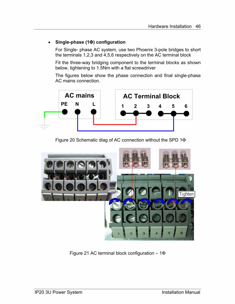
• Single-phase (1Φ) configuration For Single- phase AC system, use two Phoenix 3-pole bridges to short the terminals 1,2,3 and 4,5,6 respectively on the AC terminal block Fit the three-way bridging component to the terminal blocks as shown below, tightening to 1.5Nm with a flat screwdriver The figures below show the phase connection and final single-phase AC mains connection.
1 2 3 4 5 6
AC Terminal Block LNPE
AC mains
Figure 20 Schematic diag of AC connection without the SPD 1Φ
Figure 21 AC terminal block configuration – 1Φ
IP20 3U Power System Installation Manual
Hardware Installation 47
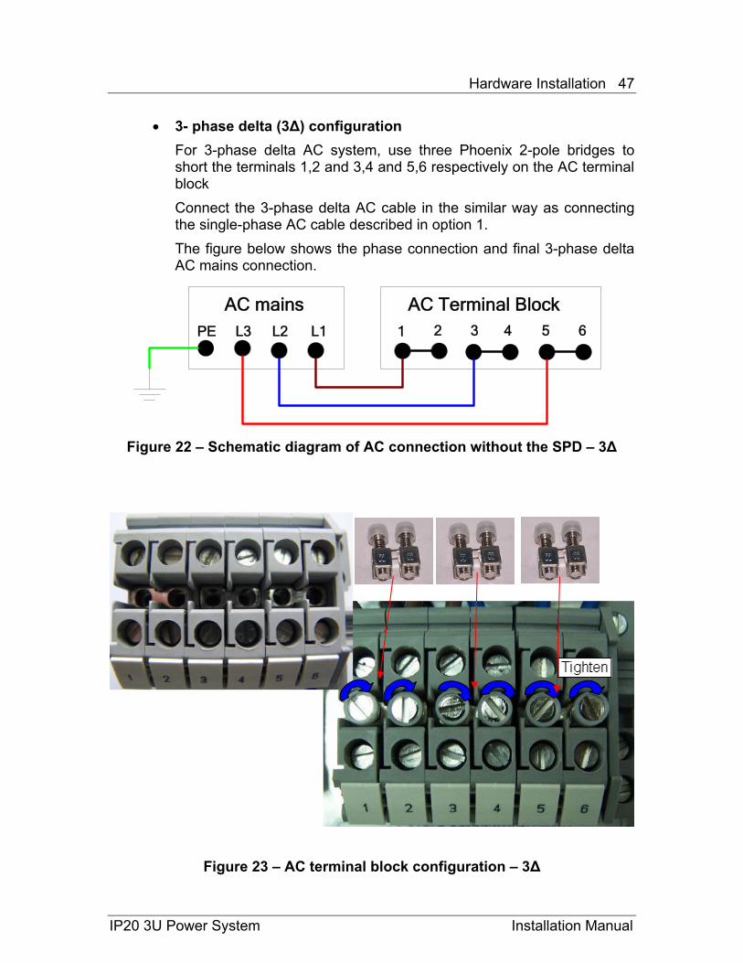
• 3- phase delta (3∆) configuration For 3-phase delta AC system, use three Phoenix 2-pole bridges to short the terminals 1,2 and 3,4 and 5,6 respectively on the AC terminal block Connect the 3-phase delta AC cable in the similar way as connecting the single-phase AC cable described in option 1. The figure below shows the phase connection and final 3-phase delta AC mains connection.
1 2 3 4 5 6
AC Terminal Block L3 L2PE
AC mainsL1
Figure 22 – Schematic diagram of AC connection without the SPD – 3∆
Figure 23 – AC terminal block configuration – 3∆
IP20 3U Power System Installation Manual
Hardware Installation 48
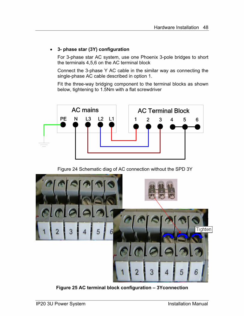
• 3- phase star (3Y) configuration For 3-phase star AC system, use one Phoenix 3-pole bridges to short the terminals 4,5,6 on the AC terminal block Connect the 3-phase Y AC cable in the similar way as connecting the single-phase AC cable described in option 1. Fit the three-way bridging component to the terminal blocks as shown below, tightening to 1.5Nm with a flat screwdriver
1 2 3 4 5 6
AC Terminal Block N L3PE
AC mainsL2 L1
Figure 24 Schematic diag of AC connection without the SPD 3Y
Figure 25 AC terminal block configuration – 3Yconnection
IP20 3U Power System Installation Manual
Hardware Installation 49
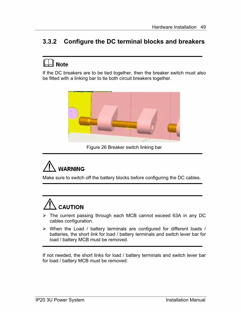
3.3.2 Configure the DC terminal blocks and breakers
If the DC breakers are to be tied together, then the breaker switch must also be fitted with a linking bar to tie both circuit breakers together.
Figure 26 Breaker switch linking bar
Make sure to switch off the battery blocks before configuring the DC cables.
The current passing through each MCB cannot exceed 63A in any DC
cables configuration. When the Load / battery terminals are configured for different loads /
batteries, the short link for load / battery terminals and switch lever bar for load / battery MCB must be removed.
If not needed, the short links for load / battery terminals and switch lever bar for load / battery MCB must be removed:
IP20 3U Power System Installation Manual
Hardware Installation 50
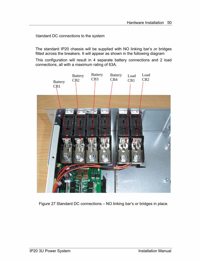
Standard DC connections to the system The standard IP20 chassis will be supplied with NO linking bar’s or bridges fitted across the breakers. It will appear as shown in the following diagram This configuration will result in 4 separate battery connections and 2 load connections, all with a maximum rating of 63A.
Battery CB3
Figure 27 Standard DC connections – NO linking bar’s or bridges in place.
Battery CB1
Load CB1
Load CB2
Battery CB4
Battery CB2
IP20 3U Power System Installation Manual
Hardware Installation 51
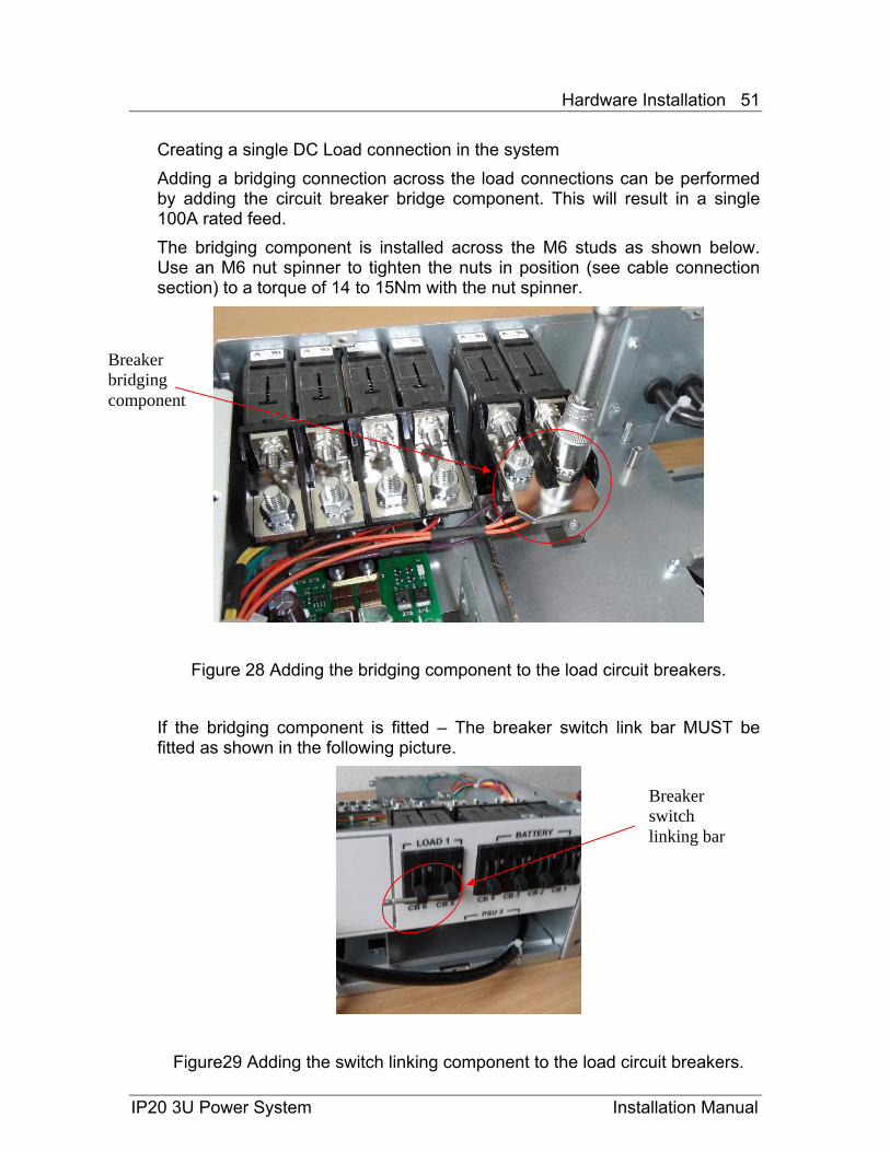
Creating a single DC Load connection in the system Adding a bridging connection across the load connections can be performed by adding the circuit breaker bridge component. This will result in a single 100A rated feed. The bridging component is installed across the M6 studs as shown below. Use an M6 nut spinner to tighten the nuts in position (see cable connection section) to a torque of 14 to 15Nm with the nut spinner.
Breaker bridging component
Figure 28 Adding the bridging component to the load circuit breakers.
If the bridging component is fitted – The breaker switch link bar MUST be fitted as shown in the following picture.
Breaker switch linking bar
Figure29 Adding the switch linking component to the load circuit breakers.
IP20 3U Power System Installation Manual

Hardware Installation 52
Creating 2 battery connections in the system. Adding similar bridging components to the battery circuit breakers will result in Two 100A rated feeds. These are installed in the same way as the load-bridge across the M6 threaded studs behind the breakers, tighten to a torque of 14 to 15Nm with a nut spinner. Note the switch bar also MUST be fitted.
Breaker bridging component
Breaker switch linking bar
Figure 30 Breaker bridge component in place and switch links fitted.
To install the switch bar across CB3 and CB4 they must both be in the ‘ON’ position. After fitting the switch link, return the breakers to their ‘OFF’ position
Figure 31 Fitting CB3/CB4 breaker switch linking bar
IP20 3U Power System Installation Manual
Hardware Installation 53
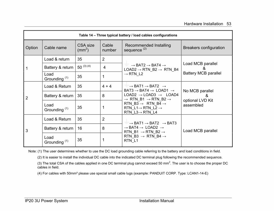
Table 14 – Three typical battery / load cables configurations
Option Cable name CSA size (mm2)
Cable number
Recommended Installing sequence (2) Breakers configuration
1
Load & return 35 2 → BAT2 → BAT4 →
LOAD2 → RTN_B2 → RTN_B4 → RTN_L2
Load MCB parallel & Battery MCB parallel
Battery & return 50 (3) (4) 4 Load Grounding (1) 35 1
2
Load & Return 35 4 + 4 → BAT1 → BAT2 → BAT3 → BAT4 → LOAD1 → LOAD2 → LOAD3 → LOAD4 → RTN_B1 → RTN_B2 → RTN_B3 → RTN_B4 → RTN_L1→ RTN_L2 → RTN_L3→ RTN_L4
No MCB parallel &
optional LVD Kit assembled
Battery & return 35 8
Load Grounding (1) 35 1
3
Load & Return 35 2 → BAT1 → BAT2 → BAT3
→ BAT4 → LOAD2 → RTN_B1 → RTN_B2 → RTN_B3 → RTN_B4 → RTN_L1
Load MCB parallel Battery & return 16 8
Load Grounding (1) 35 1
Note: (1) The user determines whether to use the DC load grounding cable referring to the battery and load conditions in field.
(2) It is easier to install the individual DC cable into the indicated DC terminal plug following the recommended sequence.
(3) The total CSA of the cables applied in one DC terminal plug cannot exceed 50 mm2. The user is to choose the proper DC cables in field.
(4) For cables with 50mm² please use special small cable lugs (example: PANDUIT CORP. Type: LCAN1-14-E)
IP20 3U Power System Installation Manual
Hardware Installation 54
IP20 3U Power System Installation Manual
Installing the system modules
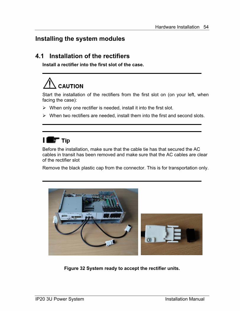
4.1 Installation of the rectifiers Install a rectifier into the first slot of the case.
Start the installation of the rectifiers from the first slot on (on your left, when facing the case):
When only one rectifier is needed, install it into the first slot. When two rectifiers are needed, install them into the first and second slots.
Before the installation, make sure that the cable tie has that secured the AC cables in transit has been removed and make sure that the AC cables are clear of the rectifier slot Remove the black plastic cap from the connector. This is for transportation only.
Figure 32 System ready to accept the rectifier units.
Hardware Installation 55
IP20 3U Power System Installation Manual
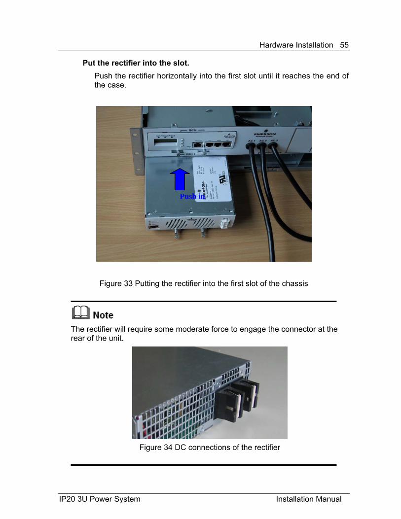
Put the rectifier into the slot. Push the rectifier horizontally into the first slot until it reaches the end of the case.
Figure 33 Putting the rectifier into the first slot of the chassis
The rectifier will require some moderate force to engage the connector at the rear of the unit.
Figure 34 DC connections of the rectifier
Push in
Hardware Installation 56
IP20 3U Power System Installation Manual
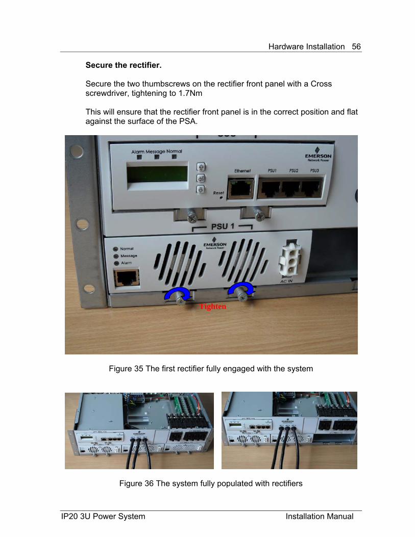
Secure the rectifier.
Secure the two thumbscrews on the rectifier front panel with a Cross screwdriver, tightening to 1.7Nm
This will ensure that the rectifier front panel is in the correct position and flat against the surface of the PSA.
Figure 35 The first rectifier fully engaged with the system
Figure 36 The system fully populated with rectifiers
Tighten
Hardware Installation 57
IP20 3U Power System Installation Manual
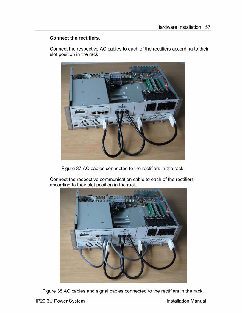
Connect the rectifiers. Connect the respective AC cables to each of the rectifiers according to their slot position in the rack
Figure 37 AC cables connected to the rectifiers in the rack.
Connect the respective communication cable to each of the rectifiers according to their slot position in the rack.
Figure 38 AC cables and signal cables connected to the rectifiers in the rack.
Hardware Installation 58
IP20 3U Power System Installation Manual
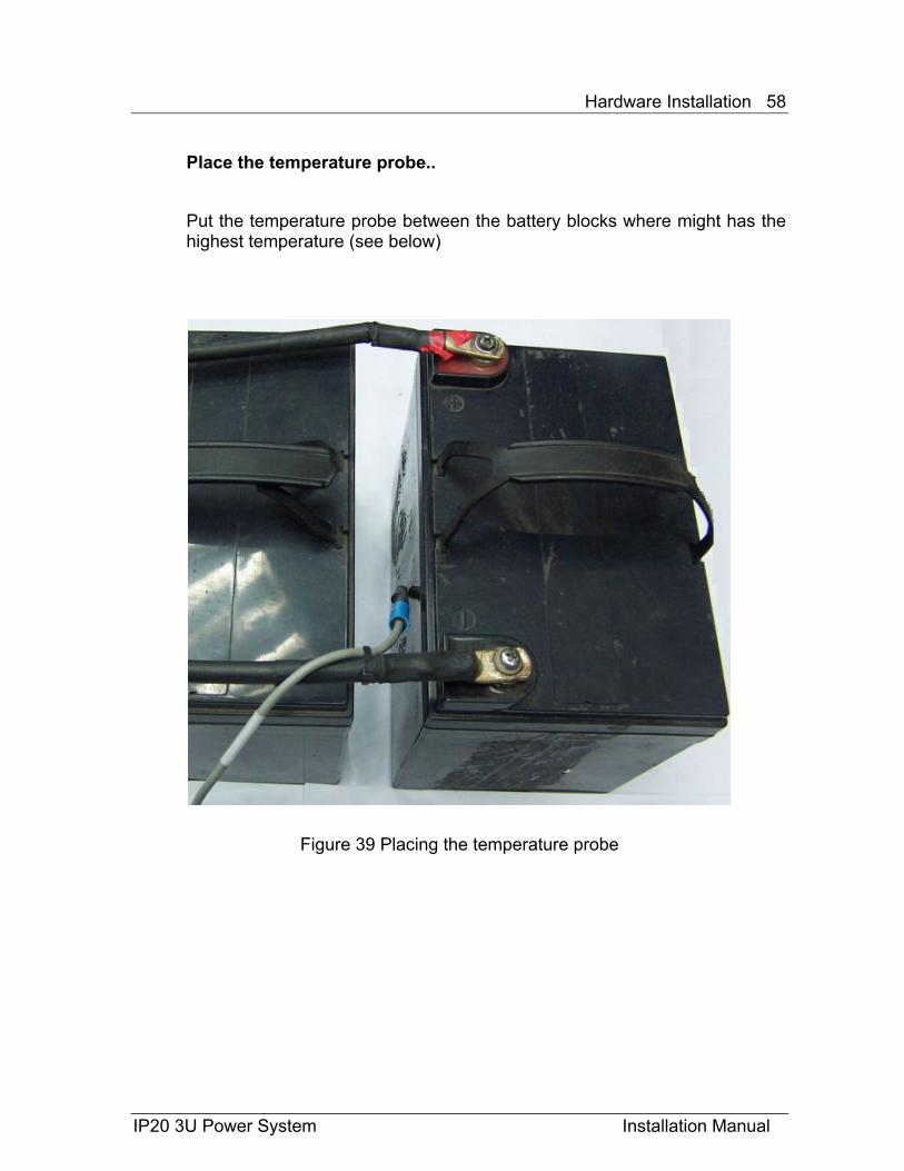
Place the temperature probe.. Put the temperature probe between the battery blocks where might has the highest temperature (see below)
Figure 39 Placing the temperature probe
Hardware Installation 59
IP20 3U Power System Installation Manual
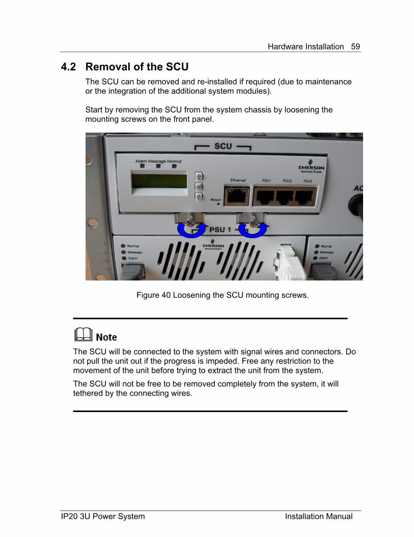
4.2 Removal of the SCU The SCU can be removed and re-installed if required (due to maintenance or the integration of the additional system modules). Start by removing the SCU from the system chassis by loosening the mounting screws on the front panel.
Figure 40 Loosening the SCU mounting screws.
The SCU will be connected to the system with signal wires and connectors. Do not pull the unit out if the progress is impeded. Free any restriction to the movement of the unit before trying to extract the unit from the system. The SCU will not be free to be removed completely from the system, it will tethered by the connecting wires.
Hardware Installation 60
IP20 3U Power System Installation Manual
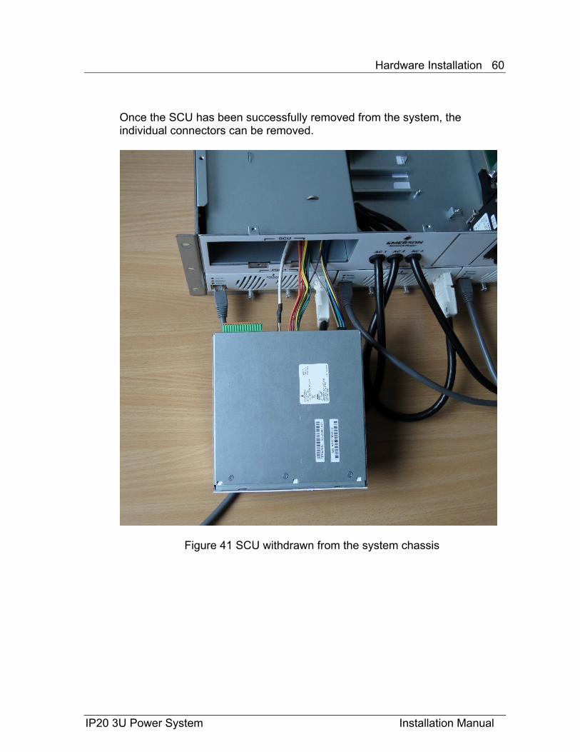
Once the SCU has been successfully removed from the system, the individual connectors can be removed.
Figure 41 SCU withdrawn from the system chassis

Hardware Installation 61
IP20 3U Power System Installation Manual
Figure 42 Removal of the SCU connectors
The alarm status connector can be removed from the unit and the signal wires can be connected to the connector as required by depressing the orange part of the connector body. The configuration of the alarms to Alarm O/P 1 through 6 is described in the User manual.
Figure 43 Releasing the Alarm signal connector.
Remove DC connector Remove CB status connector
Remove Temperature probe
Hardware Installation 62
IP20 3U Power System Installation Manual
4.3 Installation of the SCU
The installation of the SCU is the reverse of removal. Secure the two thumbscrews on the rectifier front panel with a Cross screwdriver, tightening to 1.7Nm
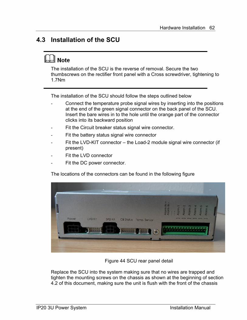
The installation of the SCU should follow the steps outlined below
- Connect the temperature probe signal wires by inserting into the positions at the end of the green signal connector on the back panel of the SCU. Insert the bare wires in to the hole until the orange part of the connector clicks into its backward position
- Fit the Circuit breaker status signal wire connector.
- Fit the battery status signal wire connector
- Fit the LVD-KIT connector – the Load-2 module signal wire connector (if present)
- Fit the LVD connector
- Fit the DC power connector.
The locations of the connectors can be found in the following figure
Figure 44 SCU rear panel detail Replace the SCU into the system making sure that no wires are trapped and tighten the mounting screws on the chassis as shown at the beginning of section 4.2 of this document, making sure the unit is flush with the front of the chassis
Hardware Installation 63
IP20 3U Power System Installation Manual
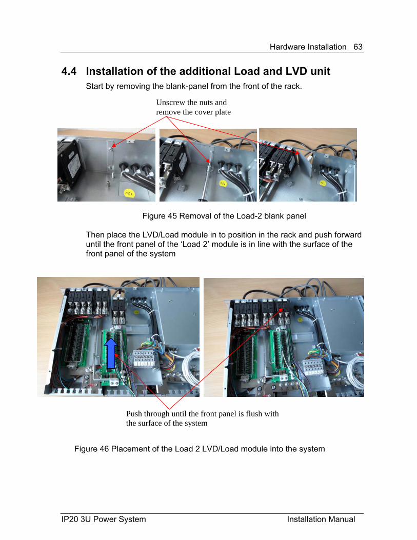
4.4 Installation of the additional Load and LVD unit Start by removing the blank-panel from the front of the rack.
Figure 45 Removal of the Load-2 blank panel Then place the LVD/Load module in to position in the rack and push forward until the front panel of the ‘Load 2’ module is in line with the surface of the front panel of the system
Figure 46 Placement of the Load 2 LVD/Load module into the system
Push through until the front panel is flush with the surface of the system
Unscrew the nuts and remove the cover plate
Hardware Installation 64
IP20 3U Power System Installation Manual
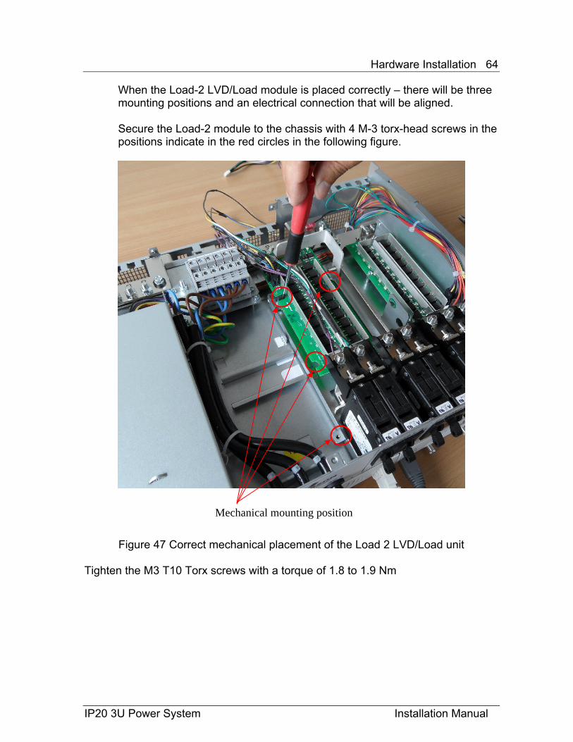
When the Load-2 LVD/Load module is placed correctly – there will be three mounting positions and an electrical connection that will be aligned. Secure the Load-2 module to the chassis with 4 M-3 torx-head screws in the positions indicate in the red circles in the following figure.
Figure 47 Correct mechanical placement of the Load 2 LVD/Load unit
Tighten the M3 T10 Torx screws with a torque of 1.8 to 1.9 Nm
Mechanical mounting position
Hardware Installation 65
IP20 3U Power System Installation Manual
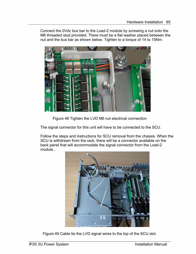
Connect the 0Vdc bus bar to the Load-2 module by screwing a nut onto the M6 threaded stud provided. There must be a flat washer placed between the nut and the bus bar as shown below. Tighten to a torque of 14 to 15Nm.
Figure 48 Tighten the LVD M6 nut electrical connection
The signal connector for this unit will have to be connected to the SCU. Follow the steps and instructions for SCU removal from the chassis. When the SCU is withdrawn from the rack, there will be a connector available on the back panel that will accommodate the signal connector from the Load-2 module..
Figure 49 Cable tie the LVD signal wires to the top of the SCU slot.
Hardware Installation 66
IP20 3U Power System Installation Manual
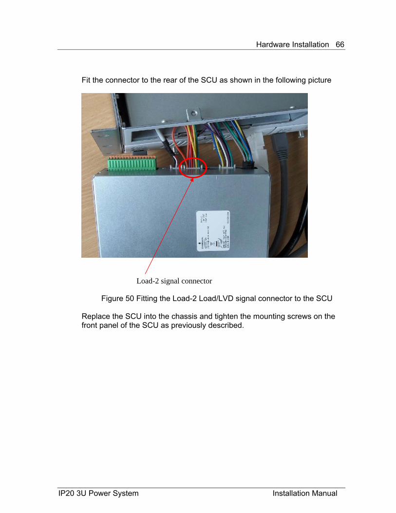
Fit the connector to the rear of the SCU as shown in the following picture
Figure 50 Fitting the Load-2 Load/LVD signal connector to the SCU
Replace the SCU into the chassis and tighten the mounting screws on the front panel of the SCU as previously described.
Load-2 signal connector
Hardware Installation 67
IP20 3U Power System Installation Manual
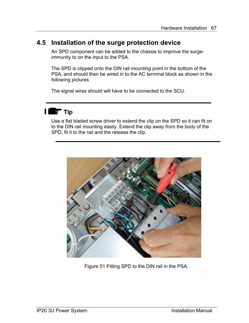
4.5 Installation of the surge protection device An SPD component can be added to the chassis to improve the surge-immunity to on the input to the PSA. The SPD is clipped onto the DIN rail mounting point in the bottom of the PSA, and should then be wired in to the AC terminal block as shown in the following pictures The signal wires should will have to be connected to the SCU.
Use a flat bladed screw driver to extend the clip on the SPD so it can fit on to the DIN rail mounting easily. Extend the clip away from the body of the SPD, fit it to the rail and the release the clip.
Figure 51 Fitting SPD to the DIN rail in the PSA.

Hardware Installation 68
IP20 3U Power System Installation Manual
Connect the AC wires to the AC terminal block in the manner shown in the set of pictures below, making sure that both ferules are in place safely and making electrical contact to the terminations. The earth connection can be made with the ring-terminal on the stud provided and as shown below
Figure 52 Wiring the SPD into the AC connections The Signal’s from the SPD have to be secured with cable-ties to the top of the SCU enclosure, and the plug is to be passed through the rear of the SCU enclosure and connected to the unit as shown below.
Figure 53 The SPD signal connections and wiring loom
Figure 54 The SPD signal connector at the SCU
SPD signal connector
Hardware Installation 69
IP20 3U Power System Installation Manual
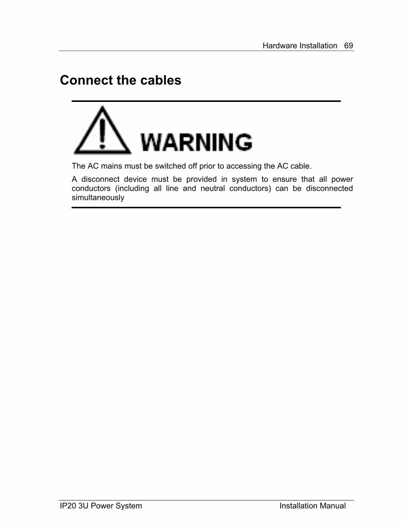
Connect the cables
The AC mains must be switched off prior to accessing the AC cable. A disconnect device must be provided in system to ensure that all power conductors (including all line and neutral conductors) can be disconnected simultaneously
Hardware Installation 70
IP20 3U Power System Installation Manual
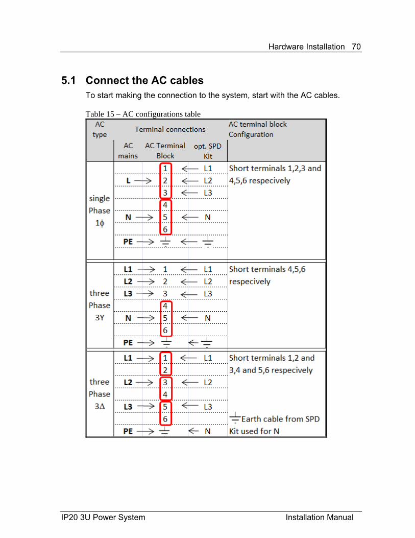
5.1 Connect the AC cables To start making the connection to the system, start with the AC cables. Table 15 – AC configurations table
Hardware Installation 71
IP20 3U Power System Installation Manual
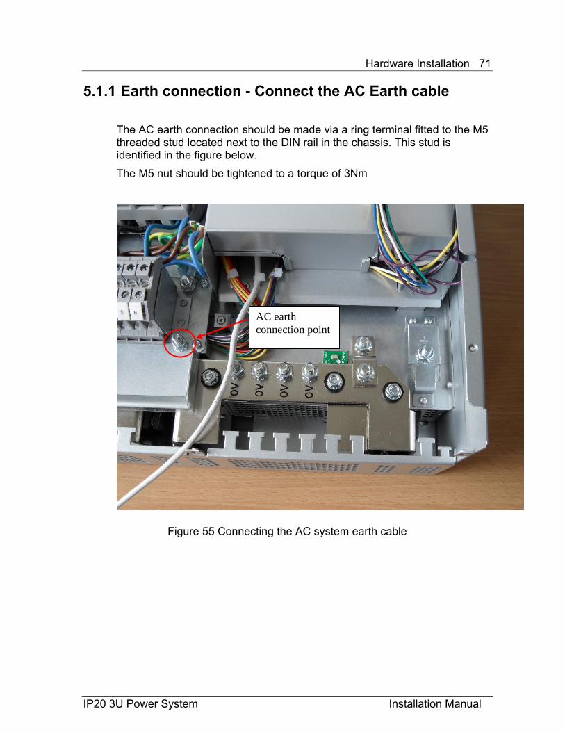
5.1.1 Earth connection - Connect the AC Earth cable The AC earth connection should be made via a ring terminal fitted to the M5 threaded stud located next to the DIN rail in the chassis. This stud is identified in the figure below. The M5 nut should be tightened to a torque of 3Nm
Figure 55 Connecting the AC system earth cable
AC earth connection point
Hardware Installation 72
IP20 3U Power System Installation Manual
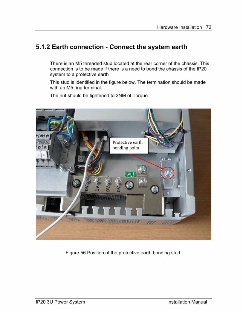
5.1.2 Earth connection - Connect the system earth There is an M5 threaded stud located at the rear corner of the chassis. This connection is to be made if there is a need to bond the chassis of the IP20 system to a protective earth This stud is identified in the figure below. The termination should be made with an M5 ring terminal. The nut should be tightened to 3NM of Torque.
Figure 56 Position of the protective earth bonding stud.
Protective earth bonding point
Hardware Installation 73
IP20 3U Power System Installation Manual
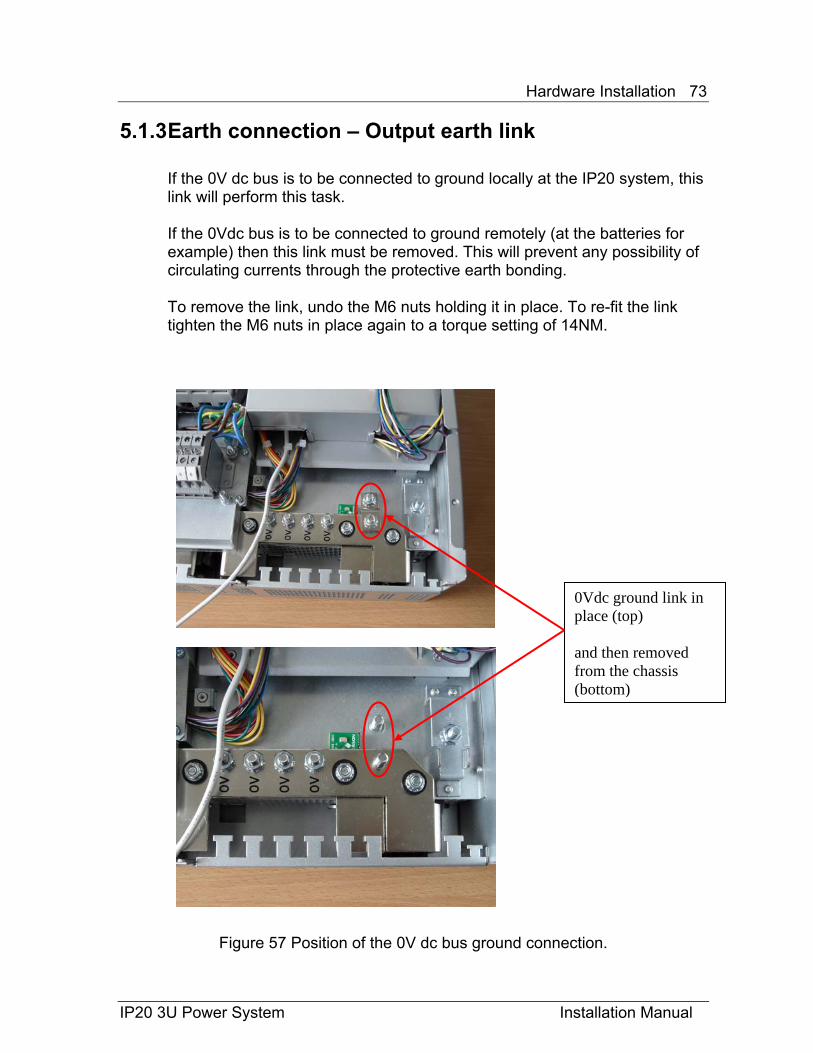
5.1.3 Earth connection – Output earth link If the 0V dc bus is to be connected to ground locally at the IP20 system, this link will perform this task. If the 0Vdc bus is to be connected to ground remotely (at the batteries for example) then this link must be removed. This will prevent any possibility of circulating currents through the protective earth bonding. To remove the link, undo the M6 nuts holding it in place. To re-fit the link tighten the M6 nuts in place again to a torque setting of 14NM.
Figure 57 Position of the 0V dc bus ground connection.
0Vdc ground link in place (top) and then removed from the chassis (bottom)
Hardware Installation 74
IP20 3U Power System Installation Manual
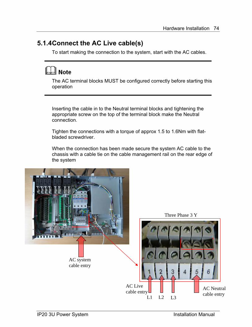
5.1.4 Connect the AC Live cable(s) To start making the connection to the system, start with the AC cables.
The AC terminal blocks MUST be configured correctly before starting this operation Inserting the cable in to the Neutral terminal blocks and tightening the appropriate screw on the top of the terminal block make the Neutral connection. Tighten the connections with a torque of approx 1.5 to 1.6Nm with flat-bladed screwdriver. When the connection has been made secure the system AC cable to the chassis with a cable tie on the cable management rail on the rear edge of the system
AC Neutral cable entry
AC Live cable entry
AC system cable entry
Three Phase 3 Y
L1 L2 L3
Hardware Installation 75
IP20 3U Power System Installation Manual
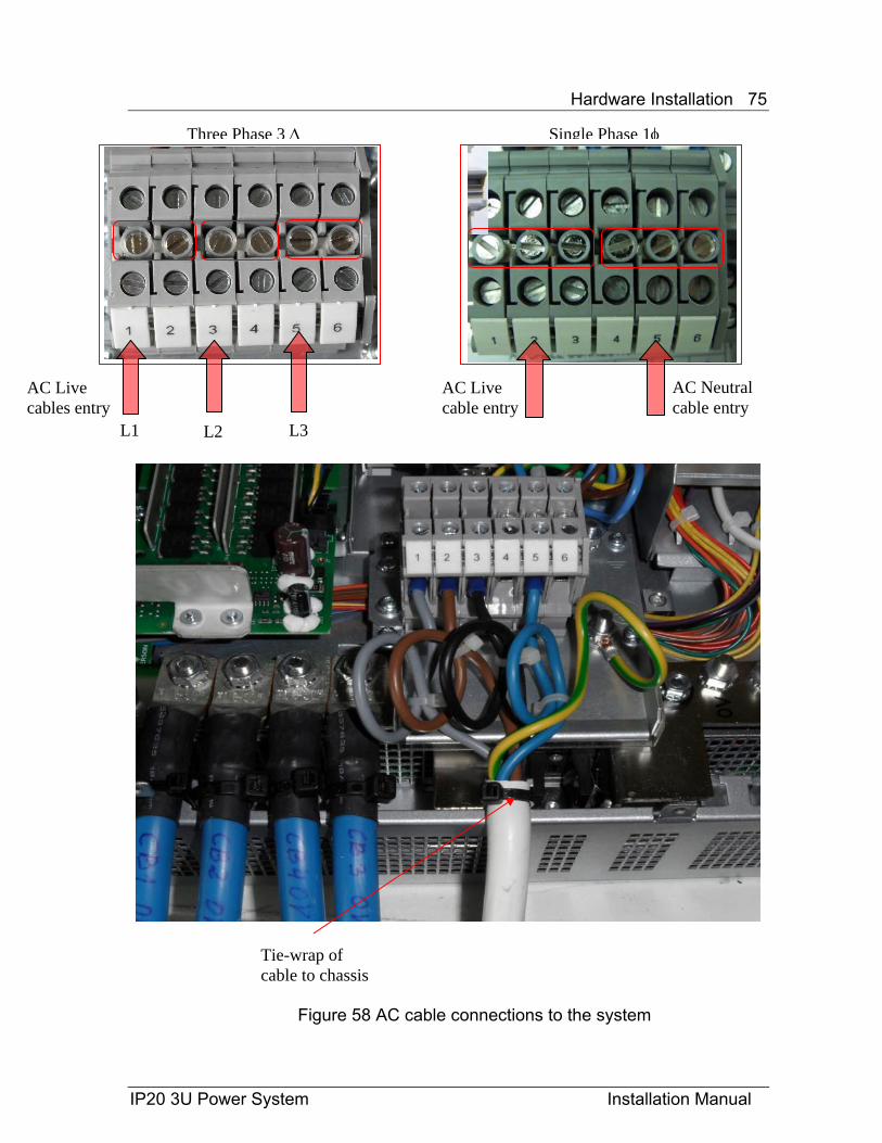
Figure 58 AC cable connections to the system
Tie-wrap of cable to chassis
AC Neutral cable entry
Three Phase 3 Δ Single Phase 1φ
AC Live cable entry
AC Live cables entry
L1 L2 L3
Hardware Installation 76
5.2 Connect the DC LOAD cables
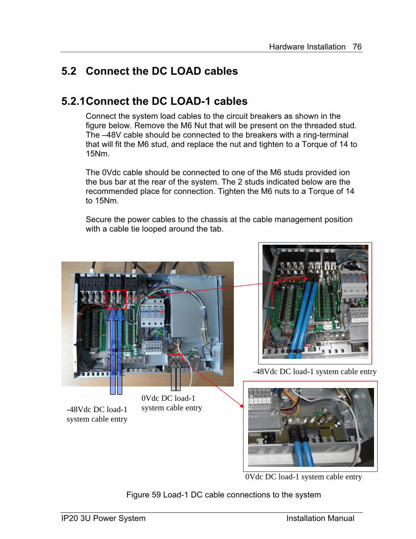
5.2.1 Connect the DC LOAD-1 cables Connect the system load cables to the circuit breakers as shown in the figure below. Remove the M6 Nut that will be present on the threaded stud. The –48V cable should be connected to the breakers with a ring-terminal that will fit the M6 stud, and replace the nut and tighten to a Torque of 14 to 15Nm. The 0Vdc cable should be connected to one of the M6 studs provided ion the bus bar at the rear of the system. The 2 studs indicated below are the recommended place for connection. Tighten the M6 nuts to a Torque of 14 to 15Nm. Secure the power cables to the chassis at the cable management position with a cable tie looped around the tab.
IP20 3U Power System Installation Manual
-48Vdc DC load-1 system cable entry
0Vdc DC load-1 system cable entry
0Vdc DC load-1 system cable entry
-48Vdc DC load-1 system cable entry
Figure 59 Load-1 DC cable connections to the system
Hardware Installation 77
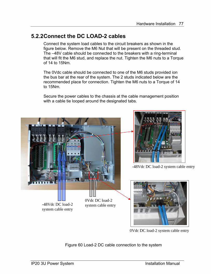
5.2.2 Connect the DC LOAD-2 cables Connect the system load cables to the circuit breakers as shown in the figure below. Remove the M6 Nut that will be present on the threaded stud. The –48V cable should be connected to the breakers with a ring-terminal that will fit the M6 stud, and replace the nut. Tighten the M6 nuts to a Torque of 14 to 15Nm. The 0Vdc cable should be connected to one of the M6 studs provided ion the bus bar at the rear of the system. The 2 studs indicated below are the recommended place for connection. Tighten the M6 nuts to a Torque of 14 to 15Nm. Secure the power cables to the chassis at the cable management position with a cable tie looped around the designated tabs.
IP20 3U Power System Installation Manual
0Vdc DC load-2 system cable entry
0Vdc DC load-2 system cable entry
-48Vdc DC load-2 system cable entry
-48Vdc DC load-2 system cable entry
Figure 60 Load-2 DC cable connection to the system
Hardware Installation 78
IP20 3U Power System Installation Manual
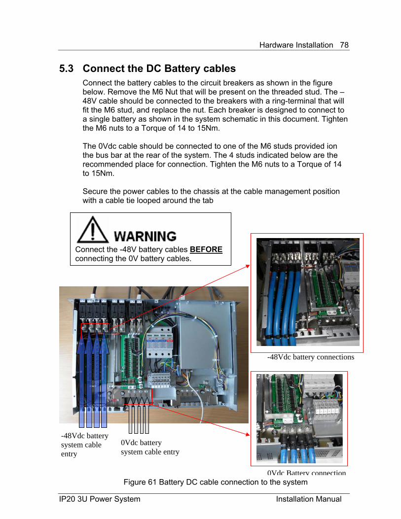
5.3 Connect the DC Battery cables Connect the battery cables to the circuit breakers as shown in the figure below. Remove the M6 Nut that will be present on the threaded stud. The –48V cable should be connected to the breakers with a ring-terminal that will fit the M6 stud, and replace the nut. Each breaker is designed to connect to a single battery as shown in the system schematic in this document. Tighten the M6 nuts to a Torque of 14 to 15Nm. The 0Vdc cable should be connected to one of the M6 studs provided ion the bus bar at the rear of the system. The 4 studs indicated below are the recommended place for connection. Tighten the M6 nuts to a Torque of 14 to 15Nm. Secure the power cables to the chassis at the cable management position with a cable tie looped around the tab
Figure 61 Battery DC cable connection to the system
-48Vdc battery connections
0Vdc Battery connection
-48Vdc battery system cable entry
0Vdc battery system cable entry
Connect the -48V battery cables BEFORE connecting the 0V battery cables.
Hardware Installation 79
IP20 3U Power System Installation Manual
Final system Assembly 6.1 Cable management
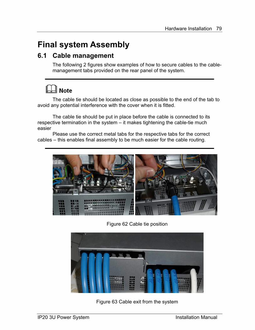
The following 2 figures show examples of how to secure cables to the cable-management tabs provided on the rear panel of the system.
The cable tie should be located as close as possible to the end of the tab to
avoid any potential interference with the cover when it is fitted. The cable tie should be put in place before the cable is connected to its
respective termination in the system – it makes tightening the cable-tie much easier
Please use the correct metal tabs for the respective tabs for the correct cables – this enables final assembly to be much easier for the cable routing.
Figure 62 Cable tie position
Figure 63 Cable exit from the system
Hardware Installation 80
IP20 3U Power System Installation Manual
The final system assembly Refit the cover to the system by pushing it back into the space provided under the front panel, then push the cover downwards
When pushing down on the cover, make sure that the cables that are now
coming out of the system are in their respective cut outs in the cover.
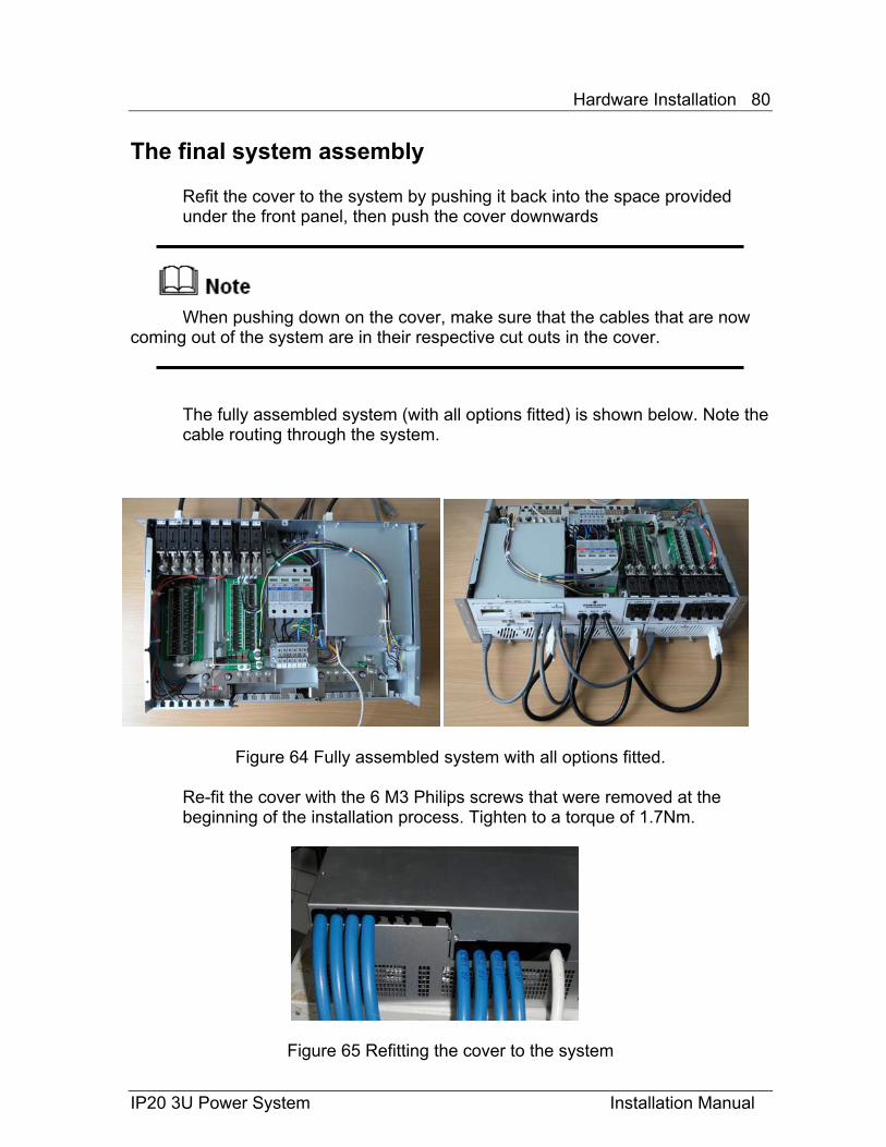
The fully assembled system (with all options fitted) is shown below. Note the cable routing through the system.
Figure 64 Fully assembled system with all options fitted.
Re-fit the cover with the 6 M3 Philips screws that were removed at the beginning of the installation process. Tighten to a torque of 1.7Nm.
Figure 65 Refitting the cover to the system
Hardware Installation 81
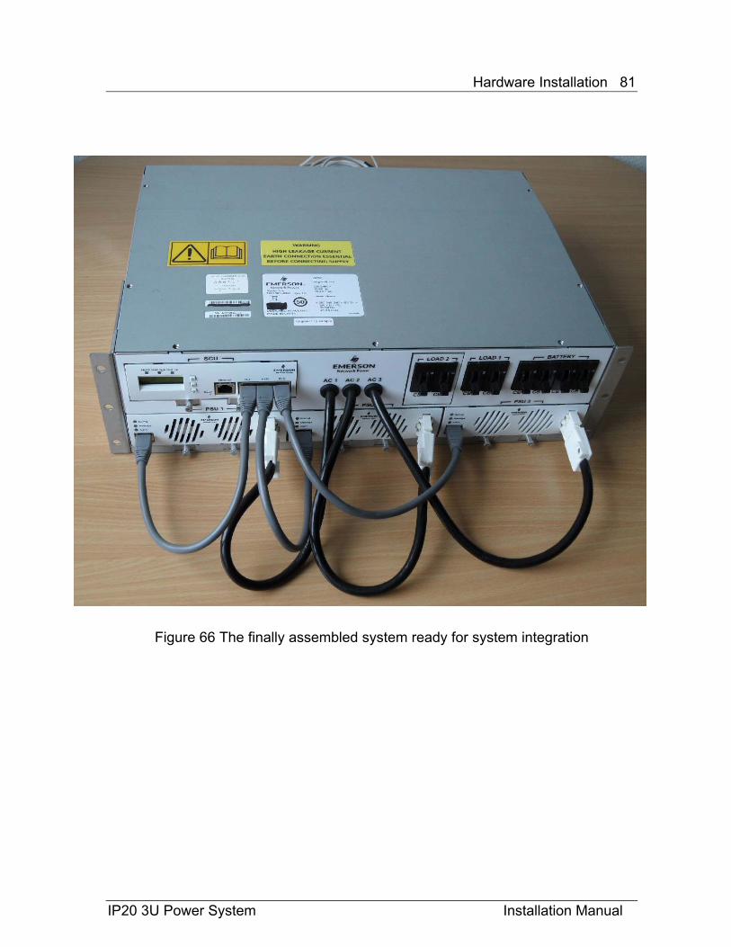
Figure 66 The finally assembled system ready for system integration
IP20 3U Power System Installation Manual
Hardware Installation 82
IP20 3U Power System Installation Manual
![Gebrauchsanweisung Basic Platte - compo-tec.de · Schutzart IP20 IP20 IP20 IP20 IP20 Gewicht 5,6 kg 4,1 kg 2,7 kg 1,8 kg 1,4 kg Abmessungen (Breite x Höhe x Tiefe) 1200x 600x 4 [mm]](https://img.dokumen.tips/doc/110x75/5b15cb637f8b9a332f8e203a/gebrauchsanweisung-basic-platte-compo-tecde-schutzart-ip20-ip20-ip20-ip20.jpg)