Embed Size (px)
Citation preview

INSTALLATION MANUAL
DIS8-BBF DISTRIBUTORLESS IGNITION SYSTEM
FOR BIG BLOCK FORD
2
TABLE OF CONTENTS KIT CONTENTS ......................................................................................... 2 INTRODUCTION ........................................................................................ 3 WASTE SPARK IGNITION – OVERVIEW .................................................. 3 REMOVE EXISTING COMPONENTS ........................................................ 4 INSTALL ELECTRONIC DISTRIBUTOR .................................................... 5 INSTALL COIL PACKS ............................................................................... 6 ASSEMBLE SPARK PLUG WIRES ............................................................ 7 FINAL ELECTRICAL CONNECTIONS ....................................................... 8 TROUBLESHOOTING ................................................................................ 9 WARRANTY ............................................................................................. 10 CONTACT COMPU-TRONIX .................................................................... 10
KIT CONTENTS VERIFY THE CONTENTS OF THE SYSTEM. It should contain the following: 1 DIS8-CHEVY Electronic Distributor 2 Four Terminal Coil Packs 8 Spark Plug Wires 8 Spark Plug Wire Terminals 8 Spark Plug Wire Boots 1 Mechanical Parts Bag 1 Electrical Parts Bag 1 Instruction Booklet W/Coil Pack Mounting Template READ THESE INSTRUCTIONS COMPLETELY BEFORE BEGINNING INSTALLATION! If you are in doubt about any of the procedures, have a qualified automotive technician install the system for you!
3
INTRODUCTION Congratulations! You have just purchased the highest performance modern ignition system available for a Big Block Ford.
These instruction sheets are precise and accurate. They are designed to take you through the installation, step by step, in a logical sequence. If you follow them, the system will work the first time, every time. If you do not follow them, Cypress Engineering cannot guarantee the results. Due to the high-energy output of this system, only 8mm silicone spark plug wires, such as the ones available from Compu-Tronix, should be used. High quality spark plugs, in new or good condition must be used. Spark plug gaps up to 0.045” may be used with this system. Use as large a spark plug gap as possible without inducing misfire. Never crank the engine with any high voltage spark plug wires disconnected from the coil pack terminals or spark plugs. This puts a very high stress on the coil and it is dangerous! DO NOT try to time this system with a dial back timing light. Each spark plug wire conducts current once per engine revolution instead of once every other revolution as in a conventional system. Use only a standard timing light with a clamp on inductive type pick up.
TECH TIP: Verify timing settings before removing any existing ignition components.
WASTE SPARK IGNITION – OVERVIEW The Compu-Tronix Distributorless Ignition System is a “waste spark” type ignition system. The spark events are controlled by the Mechanical Trigger Device and Electronic Control Module (ECM). The spark plugs are fired directly from a pair of high energy coil packs. Each coil pack has two internal coils making for a total of four coils. Each individual coil has two terminals that provide spark output to two cylinders. In a waste spark type ignition system, each cylinder is partnered with another cylinder that is phased 360° apart from it. This means both cylinders are at Top Dead Center (TDC) at the same time; one cylinder is at TDC compression while the other is at TDC exhaust. Each coil has two output terminals; one for each of the paired, out of phase, cylinders. When the ECM commands the coil packs to fire, an individual coil will provide spark to both of the paired cylinders. The spent gases in the cylinder at TDC exhaust act as a conductor and very little spark energy (1% of total available) is used to jump the plug gap. Thus, a spark is being “wasted” on the cylinder that’s on the exhaust stroke. The compressed air and fuel in the cylinder at TDC compression create a very high resistance thus requiring more spark energy (99% of total available) to jump the plug gap. This creates a very high spark that burns hot and has a long duration.
The Compu-Tronix Distributorless Ignition System uses a series of Hall Effect sensors and a
flying magnet trigger disk to trigger the ignition events. The ECM uses an advanced digital
controller to manage an adaptive dwell system. By controlling dwell, the high energy coil packs
maintain optimum spark energy output throughout the entire rpm range.
4
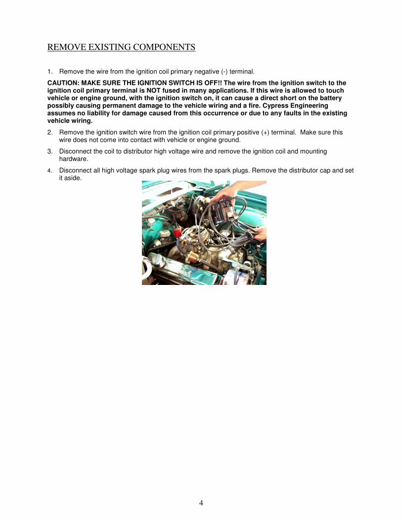
REMOVE EXISTING COMPONENTS
1. Remove the wire from the ignition coil primary negative (-) terminal.
CAUTION: MAKE SURE THE IGNITION SWITCH IS OFF!! The wire from the ignition switch to the ignition coil primary terminal is NOT fused in many applications. If this wire is allowed to touch vehicle or engine ground, with the ignition switch on, it can cause a direct short on the battery possibly causing permanent damage to the vehicle wiring and a fire. Cypress Engineering assumes no liability for damage caused from this occurrence or due to any faults in the existing vehicle wiring.
2. Remove the ignition switch wire from the ignition coil primary positive (+) terminal. Make sure this wire does not come into contact with vehicle or engine ground.
3. Disconnect the coil to distributor high voltage wire and remove the ignition coil and mounting hardware.
4. Disconnect all high voltage spark plug wires from the spark plugs. Remove the distributor cap and set it aside.
5
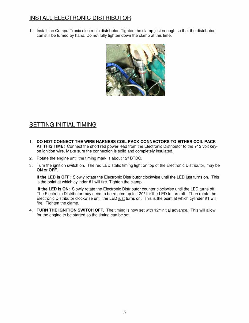
INSTALL ELECTRONIC DISTRIBUTOR
1. Install the Compu-Tronix electronic distributor. Tighten the clamp just enough so that the distributor can still be turned by hand. Do not fully tighten down the clamp at this time.
SETTING INITIAL TIMING
1. DO NOT CONNECT THE WIRE HARNESS COIL PACK CONNECTORS TO EITHER COIL PACK AT THIS TIME! Connect the short red power lead from the Electronic Distributor to the +12 volt key-on ignition wire. Make sure the connection is solid and completely insulated.
2. Rotate the engine until the timing mark is about 12º BTDC.
3. Turn the ignition switch on. The red LED static timing light on top of the Electronic Distributor, may be ON or OFF.
If the LED is OFF: Slowly rotate the Electronic Distributor clockwise until the LED just turns on. This is the point at which cylinder #1 will fire. Tighten the clamp.
If the LED is ON: Slowly rotate the Electronic Distributor counter clockwise until the LED turns off. The Electronic Distributor may need to be rotated up to 120° for the LED to turn off. Then rotate the Electronic Distributor clockwise until the LED just turns on. This is the point at which cylinder #1 will fire. Tighten the clamp.
4. TURN THE IGNITION SWITCH OFF. The timing is now set with 12° initial advance. This will allow for the engine to be started so the timing can be set.

6
INSTALL COIL PACKS The coil packs can essentially be mounted anywhere in the engine bay however it is recommended that they be mounted as close to the engine as possible. This keeps the spark plug wires short which reduces the amount of energy lost at the spark plugs. Possible mounting locations include on the valve covers, firewall, or fender wells. The coil packs could also be mounted on the side of the engine or oil pan so long as there is sufficient room and shielding from exhaust heat. When mounting the coils keep in mind that each coil pack will have two wires that go to one bank of the engine and two wires that will go the other bank of the engine. Because of this, either coil pack can be mounted on either side of the engine. For example, Coil Pack A can be mounted on either the driver side or the passenger side of the engine. Spark plug wires that cross over the top of the engine to connect to the opposite bank are usually routed in front of or behind the carburetor. Consider the length of the spark plug wires when choosing the coil pack mounting locations.
Coil Pack Mounted On Valve Cover

7
ASSEMBLE SPARK PLUG WIRES Determine the lengths of each wire before installing the spark plug terminals and boots. Use a small amount of dielectric grease to install terminals into back of boots. Review spark plug routing diagram for proper placement of each wire. NOTE: Performance will be seriously degraded If the terminals are not installed correctly.
2. Fold Wire Over Insulation 3. Slide Terminal Over Wire
4. Crimp Terminal Onto Wire 5. Ensure Terminal Is Fully Crimped
1. Strip Off ~1” Of Insulation

8
FINAL ELECTRICAL CONNECTIONS MAKE SURE THE IGNTION SWITCH IS OFF! 1. Connect each spark plug wire to the appropriate coil pack terminal and spark plug. Refer to the
diagram on pg. 12. NOTE: Each coil pack has two internal coils. Each of these coils has two terminals. Because each individual coil shares two cylinders, the respective spark plug wires can be connected to EITHER terminal. For example, the spark plug wires from cylinders 5 & 8 can connect to either the terminal marked 5 OR the terminal marked 8 because they share the same coil.
2. Add fuse connector onto the end of the longer, heavier gauge RED wire. CAUTION: DO NOT ATTEMPT TO USE THIS SYSTEM WITHOUT THE INLINE 20 AMP FUSE!! FAILURE TO DO SO MAY RESULT IN DAMAGE TO THE IGNITION SYSTEM! Install the appropriate ring terminal onto the end of the fuse connector wire and connect to the positive (+) battery terminal.
3. Connect the Electronic Distributor connectors to their respective coil pack connectors (A to A, B to B). The connectors will only go one way and have a spring clip to hold them together. Push the spring wire on the Electronic Distributor connector down to insert or remove the connector from the coil pack connector. Make sure the connectors are fully seated and that the spring clip locks in place when released.
4. Connect the shorter, smaller gauge RED wire to the vehicles positive (+) 12 volt key-on ignition switch wire. Use the supplied male or female spade connectors.
5. Connect the PURPLE wire to the tach input signal if applicable. Use the supplied male or female spade connectors. If a tach is not being used, simply tape the end of the wire with electrical tape
6. Make sure all wire is properly routed and not in direct contact with any hot or moving parts.
7. Start the engine. The engine is timed in the conventional manner using a conventional timing
light with an inductive pick up clamp. The inductive pick up should be clamped around #1
spark plug wire. If the timing light is weak, reverse the orientation of the inductive pick up
on the spark plug wire. If a dial back timing light is used, the dial back setting must be set
to zero. The timing should be set for maximum advance with the engine running above 3,200
rpm.

9
10
TROUBLESHOOTING DO NOT ATTEMPT TO SEE IF THE SYSTEM IS FIRING BY DISCONNECTING A SPARK PLUG WIRE AND HOLDING IT NEXT TO GROUND. THE HIGH VOLTAGE CREATED BY THIS PROCEDURE STRESSES THE INSULATION AT THE COIL AND IS VERY DANGEROUS! Engine cranks but does not start – No spark present Determine if the red LED light flashes on and off when the engine is cranked. If it does, the ignition switch wire connection is good and the Electronic Distributor is triggering correctly. If the red LED stays off, the Electronic Distributor is not getting 12 volts from the ignition switch wire. Verify that there is 12 volts present at the ignition switch wire when the ignition switch is turned on. Verify that the Electronic Distributor connectors are both fully inserted and seated into the Coil Pack Connectors. Engine starts but backfires/misfires The spark plug wires may be connected incorrectly. Recheck that the spark plug wires are connected as shown on page 12.
Make sure all rubber boots on the spark plug wires are fully seated at both the coil pack and
spark plug ends.
WARRANTY Compu-Tronix warrants its products, to the original purchaser, against defects in material and workmanship for a period of one year from the date of purchase. This warranty is limited to repair or replacement of the original part. Proof of purchase must accompany any warranty claim. No returned goods will be accepted without an RMA (Return Material Authorization) number clearly marked on the shipping container. Because electrical and electronic components can be damaged by improper installation and use, Compu-Tronix retains the sole discretion to decide whether or not a component failure was caused by defects in material or workmanship.
CONTACT COMPU-TRONIX Compu-Tronix 20470 Carrey Rd. Walnut, CA 91789 Phone: 909-598-0220 Fax: 909-444-9892 Sales Inquires: [email protected] Tech Support: [email protected]
Compu-Tronix is a division of Cypress Engineering.