Embed Size (px)
Citation preview

www.aquafilter.com
Installation Manual

2. Product Description
®Aquafilter EXCITO is a modern filtration system designed for the purification of potable and general-use water. Equipped with four in-line cartridges, the system effectively removes: rust, sand and sediments (cartridges: AIPRO-20MS and AIPRO-1MS); organic contaminants and chlorine (cartridge AICRO-L3); heavy metals such as lead, arsenic, cadmium as well as iron contents (AICRO-L4).
1. Safety Precautions
Product may be installed only by trained service professionals. Only original replacement parts, filter cartridges and accessories made by manufacturer may be used. Compliance with the following instructions ensures:- problem-free product operation,- manufacturer's warranty.
Failure to comply with the following instructions will result in loss of warranty.
1) The system is designed for the filtration of potable water only.2) Remember to remove safety clip before removing flexible tubing and elbow.
®Only original Aquafilter replacement cartridges may be used. Using cartridges made by other manufacturers results in a loss of warranty and relieves the manufacturer of responsibility for the incorrect operation of system.
EN
Inlet water temperature.............................................................................................................................................between 2°C and 23°CWater supply pressure......................................................................................................................................................................... 6 barWater supply adapter.............................................................................................................................................................................1/2”Outlet tubing..........................................................................................................................................................................................1/4”Dimensions (height x width x depth).................................................................................................................390 mm x 355 mm x 100 mm
3. Technical Specifications
Flexible tubingKTPE14W*
Shut-off valve SEWBV1414*
Water filtration System EXCITO
Chrome-plated adapter FT02
(3/4" MIP x 3/4" FIP)
brak w zestawie - dodatkowe wyposa¿enie.
Chrome-plated adapter FT07
(3/4" MIP x 3/4" FIP x 1/4" FIP)
Teflon tapeTAS0004*
Chrome-plated adapterFT06*
(1/2” MIP x 1/2” FIP x 1/4” FIP)
4. Included in the Box
Installation manualXI-EXCITO
WARNING! The system should not be used with biologically contaminated water or water of unknown origin.
IMPORTANT NOTE! The system must be secured from high pressures and rapid pressure changes caused by local water supply systems. Pressure regulator must be installed on the inlet of the system's water supply. The system's optimal performance pressure is 3.5 bar - pressure regulator must also be set to this parameter. Failure to install pressure regulator will result in loss of warranty. Regulator may be purchased separately - catalog nr. ADV-REG_K, -CR .ADV-REG _K
Installation Manual Èíòñðóêöèÿ ìîíòàæà
Instrukcja monta¿u
www.aquafilter.com
* Components are placed inside of filter housing.
Pressure regulator ADV-REG _K
ADV-REG-CR_K(not included in the set)
ChromeplatedFaucet
FXFCH17-C

®5. Connection Scheme for Aquafilter Excito
A
B
Ch
rom
e-p
late
d
ad
ap
ter
FT
06
Shut-off ball valveSEWBV1414
Cold water
Flexible Tubing Connections
A. Water inlet connection
B. Faucet connection
6. Connecting Flexible Tubing with Quick Connectors: Type JG (John Guest) and QC (Quick Connector)
Disconnecting Flexible Tubing:1) Remove safety clips from quick connector (Fig. 1).2) Press on the flange of quick connector (Fig. 2).3) Pull out flexible tubing (Fig. 3).
Connecting Flexible Tubing:1) Insert flexible tubing 1.5 cm (0.6 in) deep into the quick connector (Fig. 4).2) Insert safety clip (Fig. 5).
Fig. 1 Fig. 2 Fig. 3 Fig. 4 Fig. 5
6.1. Removing and Installing the Elbow in Quick Connector
Removing elbow from cartridge:1) Remove safety clip from quick connector (Fig. 1).2) Press on the flange of quick connector and remove the elbow (Fig. 2).
Installing the elbow into cartridge:1) Insert the elbow into quick connector to the point of resistance (Fig. 3).2) Insert safety clip (Fig. 4).
Fig. 1 Fig. 2 Fig. 3 Fig. 4
Pressure regulator ADV-REG _K*(not included in the set)
*Pressure regulator ADV-REG_K must be installed in systems with capillary membrane.

6.2. Instructions for connecting and disconnecting filter cartridge and elbow connector (new filter cartridge with elbow connector)
Disconnecting elbow connector from filter cartridge:1) Remove safety clips from quick connector (fig.1).2) Push quick connector's flange symmetrically and pull the tubing out (fig. 2).3) Unscrew inlet and outlet connectors from old filter cartridge (fig.3)4) Remove old Teflon tape (fig.4).5) Apply mutliply layers of new Telfon tape (ensure that Telflon tape is winded in the opposite direction to the direction connector will be installed) (fig. 5).
Connecting elbow connector with filter cartridge:1) Screw the elbow connector back to new filter cartridge.NOTE! Do NOT remove elbow connector after the installation has been started. Stopping and removing (unscrewing) the element may result in inadequate connection and water leak. (fig.6).
Fig. 1 Fig. 2 Fig. 3 Fig. 4 Fig. 5 Fig. 6
7. System Installation - Stage I
IMPORTANT NOTE! Manufacturer is not responsible for any damages that result from improper installation or use of system. System installation should be performed only in temperatures above 2°C (35.6°F).IMPORTANT NOTE: Before installing the system, remove from the filter housing all components necessary for installation.
Screw chrome-plated adapter onto the shut-off valve to allow easy installation of SEWBV1414 valve and its easy opening and closing.IMPORTANT NOTE! Remember to place rubber gaskets in between the connections.
Wind a few layers of Teflon Tape (TAS0003) on shut-off valve adapter (SEWBV1414).
3 4
Unscrew flexible tubing from the shut-off valve (the adapter).IMPORTANT NOTE! Between the shut-off valve and flexible tubing is a rubber gasket - be sure not to lose it.
Shut off cold water supply valve.
1 2

7
Connect flexible tubing of SEWBV1414 valve with system's water inlet [IN] (red ring).
Screw SEWBV1414 valve into chrome-plated adapter FT06.
Place the nut on flexible tubing and connect it with SEWBV1414 valve. Next, push the tubing all the way into the valve and tighten the nut.
5 6
7.1 System Installation - Wall Faucet Connection
Unscrew the faucet from the wall. Shut off water supply valve.
1 2
3 4
IMPORTANT NOTE! Manufacturer is not responsible for any damages that result from improper installation or use of system. System installation should be performed only in temperatures above 2°C (35.6°F).IMPORTANT NOTE: Before installing the system, remove from the filter housing all components necessary for installation.
Wind a few layers of Teflon Tape TAS0003 on shut-off valve adapter SEWBV 1414.
Screw chrome-plated adapter FT07 onto the cold water pipe to allow easy installation of SEWBV1414 valve and its easy opening and closing.IMPORTANT NOTE! Remember to place rubber gaskets in between the connections.

5 6
Screw SEWBV1414 valve into chrome-plated adapter FT07.
Place the nut on flexible tubing and connect it with SEWBV1414 valve. Next, push the tubing all the way into the valve and tighten the nut.
9
Connect flexible tubing of SEWBV1414 valve with system's water inlet [IN] (red ring).
Screw chrome-plated adapter FT02 onto the hot water pipe. IMPORTANT NOTE! Remember to place rubber gaskets in between the connections.
Screw the wall faucet to the installed adapters.
7 8

1
2
3
4
5
6
7
8
9
10
11
1) Drill a 12 mm opening in a kitchen counter or kitchen sink (in case of enamel sinks, the manufacturer recommends drilling openings in the structure supporting sink).
2) On threaded faucet extension [1], first put on cover plate [2], and then rubber gasket [3].
3) Secure the faucet in the drilled sink/counter opening. 4) Underneath the sink, put the rubber [5] and metal [6]
washers on the faucet extension [4], and tighten with metal nut [7].
5) Install flexible tubing (supplying water and connecting faucet with the system):
- put the tubing [11] through the metal nut [10] and plastic tightening ring [9],
- put the insert [8] into the tubing, push flexible tubing (all the way) into the faucet extension
[4] and tighten it (by hand!) with the metal nut [10].6) Connect other end of flexible tubing with connector [OUT]
(white ring) (Fig. 2).
Fig. 2 Connecting flexible tubing with [OUT] connector
8. System Installation - Stage II - FXFCH5, FXFCH17-C Faucet Installation
Fig. 1 Installing filter faucet on kitchen counter
COUNTERTOP
WATER SUPPLY INLET
AIP
RO
-20
MS
AIP
RO
-1M
S
AIC
RO
-L3
AIC
RO
-L4
®9. Cartridge Connection Scheme in Aquafilter EXCITO System

WATER SUPPLY INLET
WATER SUPPLY INLET
AIP
RO
-20
MS
AIP
RO
-3-L
AIC
RO
-L3
AIC
RO
-L4
AIP
RO
-20
MS
AIP
RO
-3-L
AIC
RO
-L4
TL
CH
F-F
P
9.1 Cartridge Connection Scheme (set EXCITO-CLR-CRT)
9.2 Cartridge Connection Scheme (set EXCITO-HF-CRT)

11. Replacement Cartridges
AIPRO-1MS Polypropylene cartridge removes sediments such as rust, sand and suspended solids.
AIPRO-3-L Three layer cartridge:- Polypropylene foam - removes sand, rust and other suspended matters,- Conditioning media - removes iron and iron derivative compounds.- Ion exchange filtration media - acts as water softener, exchanges ions of calcium and magnesium into ions of sodium preventing scale build-up,
AIPRO-20MS Polypropylene cartridge removes sediments such as rust, sand and suspended solids.
® ®Aquafiter offers three sets of cartridges for Aquafilter EXCITO systems:
Cartridge Type Description / Filtration StagesLongevity**
AICRO-L3 Granulated activated carbon cartridge made of the high grade activated coconut carbon. It is designed to remove up to 99% of chlorine, sediments and organic contaminants. It also improves the taste and aroma of water.
AICRO-L4 Granulated activated carbon cartridge made of the high grade activated coconut carbon. It is designed to remove up to 99% of chlorine, sediments and organic contaminants. In addition, a special filtration media removes heavy metals such as lead, nickel, chromium and many others. It also improves the taste and aroma of water.
TLCHF-FP Capillary membrane removes microscopic bacteria in size of 0.02 micron and larger.
AIPRO-20MS
AIPRO-1MS
AICRO-L3
AICRO-L4
AIPRO-3-L
TLCHF-FP
4000l 3 - 6
3 - 6
3 - 6
3 - 6
3 - 6
6 - 12
4000l
4000l
4000l
4000l
5000l
Liters Months
AIPRO-20MS AIPRO-20MS AIPRO-20MS
AIPRO-1MS AIPRO3-L AIPRO-3-L
AICRO-L3 AICRO-L3 AICRO-L4
AICRO-L4 AICRO-L4 TLCHF-FP*
EXCITO-HF-CRTEXCITO-CRTNAME OF SET
CARTRIDGE 1
CARTRIDGE 2
CARTRIDGE 3
CARTRIDGE 4
EXCITO-CLR-CRT
Before the first use and after each cartridge replacement procedure, the system should be flushed with 15 liters of water. Next, allow the system to standby for 5-6 hours to activate the filtration media. After these procedures, the water is ready for consumption.
IMPORTANT NOTE! Used cartridges may not be returned.
**depends on water quality and level of contamination.
10. Cartridge Sets
* capillary membrane is sold separately.

12. Filter cartridge replacement – General information
12.1. Filter cartridge replacement – System equipped with quick connect type cartridges
Shut off water supply valve. Open filter faucet to release pressure from the system.
Unscrew the holding screw and remove front panel of the system's housing.
Before replacing the membrane, disconnect all flexible tubing from the system (inlet / outlet).
2
4
Remove the elbows: one from the water inlet of the first cartridge; one from the water outlet of the last cartridge.IMPORTANT NOTE! While removing the elbows, be careful not to bend flexible tubing.
Unpin all cartridges together from the mounting clips.
1 2
3
IMPORTANT NOTE! Before removing flexible tubing and elbow, remove safety clip and symmetrically push in the flange of quick connector. After installing flexible tubing and installing the elbow, remember to insert safety clip of the quick connector.
1
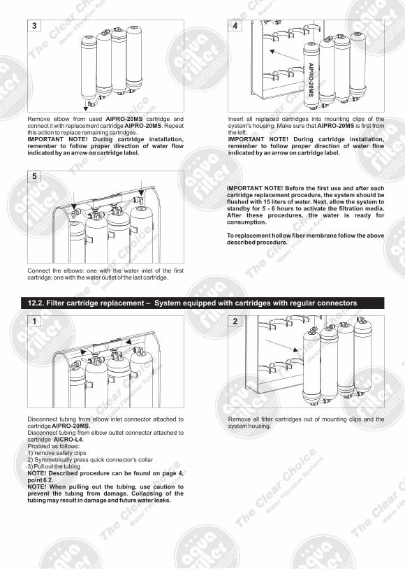
Insert all replaced cartridges into mounting clips of the system's housing. Make sure that AIPRO-20MS is first from the left.IMPORTANT NOTE! During cartridge installation, remember to follow proper direction of water flow indicated by an arrow on cartridge label.
Remove elbow from used AIPRO-20MS cartridge and connect it with replacement cartridge AIPRO-20MS. Repeat this action to replace remaining cartridges.IMPORTANT NOTE! During cartridge installation, remember to follow proper direction of water flow indicated by an arrow on cartridge label.
AIP
RO
-20
MS
Connect the elbows: one with the water inlet of the first cartridge; one with the water outlet of the last cartridge.
5
12.2. Filter cartridge replacement – System equipped with cartridges with regular connectors
Disconnect tubing from elbow inlet connector attached to cartridge AIPRO-20MS.Disconnect tubing from elbow outlet connector attached to cartridge AICRO-L4.Proceed as follows:1) remove safety clips2) Symmetrically press quick connector's collar3) Pull out the tubingNOTE! Described procedure can be found on page 4, point 6.2.NOTE! When pulling out the tubing, use caution to prevent the tubing from damage. Collapsing of the tubing may result in damage and future water leaks.
Remove all filter cartridges out of mounting clips and the system housing.
IMPORTANT NOTE! Before the first use and after each cartridge replacement procedure, the system should be flushed with 15 liters of water. Next, allow the system to standby for 5 - 6 hours to activate the filtration media. After these procedures, the water is ready for consumption.
To replacement hollow fiber membrane follow the above described procedure.

Unscrew inlet and outlet connectors from AIPRO-20MS filter housing.
Remove old Teflon tape out of the connectors thread surface.
Apply several layers of Teflon tape to the connectors threads.NOTE! Use only Teflon tape, do not use tow.NOTE! Apply Teflon tape in the opposite direction to the direction connectors will be installed.
Disconnect tubing from elbow outlet connected to cartridge AICRO-20MS.
Proceed as follows:1) Remove safety clips2) Symmetrically press quick connector's collar3) Pull out the tubingNOTE! Described procedure can be found on page 4, point 6.2. NOTE! When pulling out the tubing, use caution to prevent the tubing from damage. Collapsing of the tubing may result in damage and future water leaks.
Install (screw in) connectors into new filter cartridge.NOTE! During installing (screwing in) individual connectors do NOT withdraw (unscrew) them at any time. This may result in connection damage and future water leaks.
Connect tubing with elbow outlet connector attached to AIPRO-20MS filter cartridge.Proceed as follows:1) Ensure that new filter cartridge is placed in accordance with the direction of system's water flow.2) Insert tubing into outlet elbow connector attached to cartridge AIPRO-20MS (correctly inserted tubing is mounted 1.5 cm deep inside elbow connector).3) Secure the connection with safety clip.NOTE! Described procedure can be found on page 4, point 6.2.NOTE! When pulling out the tubing, use caution to prevent the tubing from damage. Collapsing of the tubing may result in damage and future water leaks.
In order to complete installation of the remaining replacement cartridges, repeat the procedures described in points 1-9.
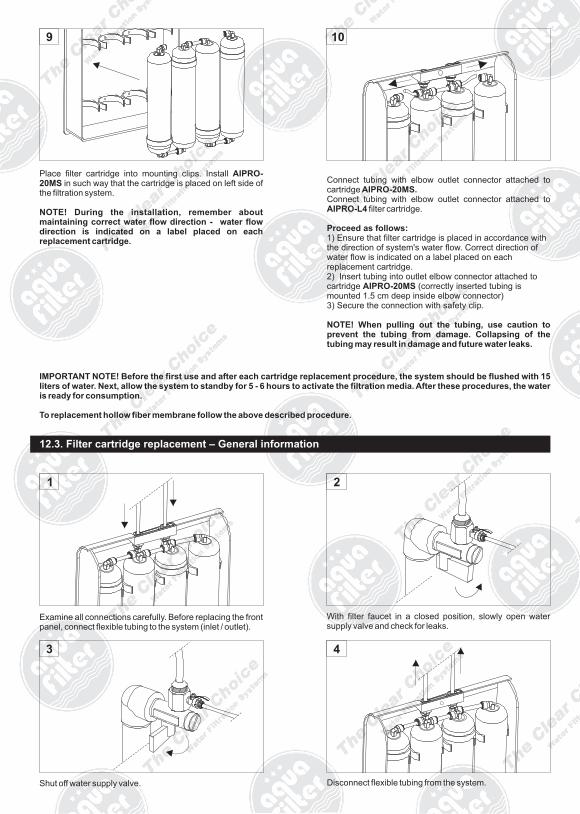
Place filter cartridge into mounting clips. Install AIPRO-20MS in such way that the cartridge is placed on left side of the filtration system.
NOTE! During the installation, remember about maintaining correct water flow direction - water flow direction is indicated on a label placed on each replacement cartridge.
Connect tubing with elbow outlet connector attached to cartridge AIPRO-20MS.Connect tubing with elbow outlet connector attached to AIPRO-L4 filter cartridge.
Proceed as follows:1) Ensure that filter cartridge is placed in accordance with the direction of system's water flow. Correct direction of water flow is indicated on a label placed on each replacement cartridge.2) Insert tubing into outlet elbow connector attached to cartridge AIPRO-20MS (correctly inserted tubing is mounted 1.5 cm deep inside elbow connector)3) Secure the connection with safety clip.
NOTE! When pulling out the tubing, use caution to prevent the tubing from damage. Collapsing of the tubing may result in damage and future water leaks.
IMPORTANT NOTE! Before the first use and after each cartridge replacement procedure, the system should be flushed with 15 liters of water. Next, allow the system to standby for 5 - 6 hours to activate the filtration media. After these procedures, the water is ready for consumption.
To replacement hollow fiber membrane follow the above described procedure.
Examine all connections carefully. Before replacing the front panel, connect flexible tubing to the system (inlet / outlet).
With filter faucet in a closed position, slowly open water supply valve and check for leaks.
21
12.3. Filter cartridge replacement – General information
Disconnect flexible tubing from the system.
4
Shut off water supply valve.
3

Connect flexible tubing to the system (inlet / outlet).
6
Replace the front panel and screw it with the housing.
5
With filter faucet in an open position, slowly open water supply valve.
7
IMPORTANT NOTE! Before the first use and after each cartridge replacement procedure, the system should be flushed with 15 liters of water. Next, allow the system to standby for 5 - 6 hours to activate the filtration media. After these procedures, the water is ready for consumption.