Embed Size (px)
Citation preview

Revised 4/4/2014
Installation, Maintenance and
Troubleshooting Guide
VS-M-18 36” x 48” VariableSpeed Limit™ Sign VS-M-18 48” x 60” VariableSpeed Limit™ Sign

Revised 4/4/2014
Revised 4/4/2014
Table of Contents
OVERVIEW ............................................................................................................................................ 1
REQUIRED COMPONENTS ................................................................................................................ 2
SOLAR POWER SYSTEM ................................................................................................................... 4
SIGN MOUNTING ................................................................................................................................. 6
SIGN INSTALLATION AND ALIGNMENT ............................................................................................ 7
STRAPPING SIZE RECOMMENDATIONS .......................................................................................... 7
SOLAR PANEL INSTALLATION .......................................................................................................... 8
SOLAR POWER BATTERY BOX ........................................................................................................ 10
GROUNDING ....................................................................................................................................... 11
RADIO INSTALLATION ....................................................................................................................... 11
BACK PANEL COMPONENTS ............................................................................................................ 12
CONTROLLER FIRMWARE UPDATING ........................................................................................... 13
MAINTENANCE ................................................................................................................................... 13
TROUBLE SHOOTING ........................................................................................................................ 14
CONTACT INFORMATION – SALES AND SUPPORT ....................................................................... 15

Revised 4/4/2014
Information Display Company VS-M18 Display Manual Revised 4/4/2014 Page 1
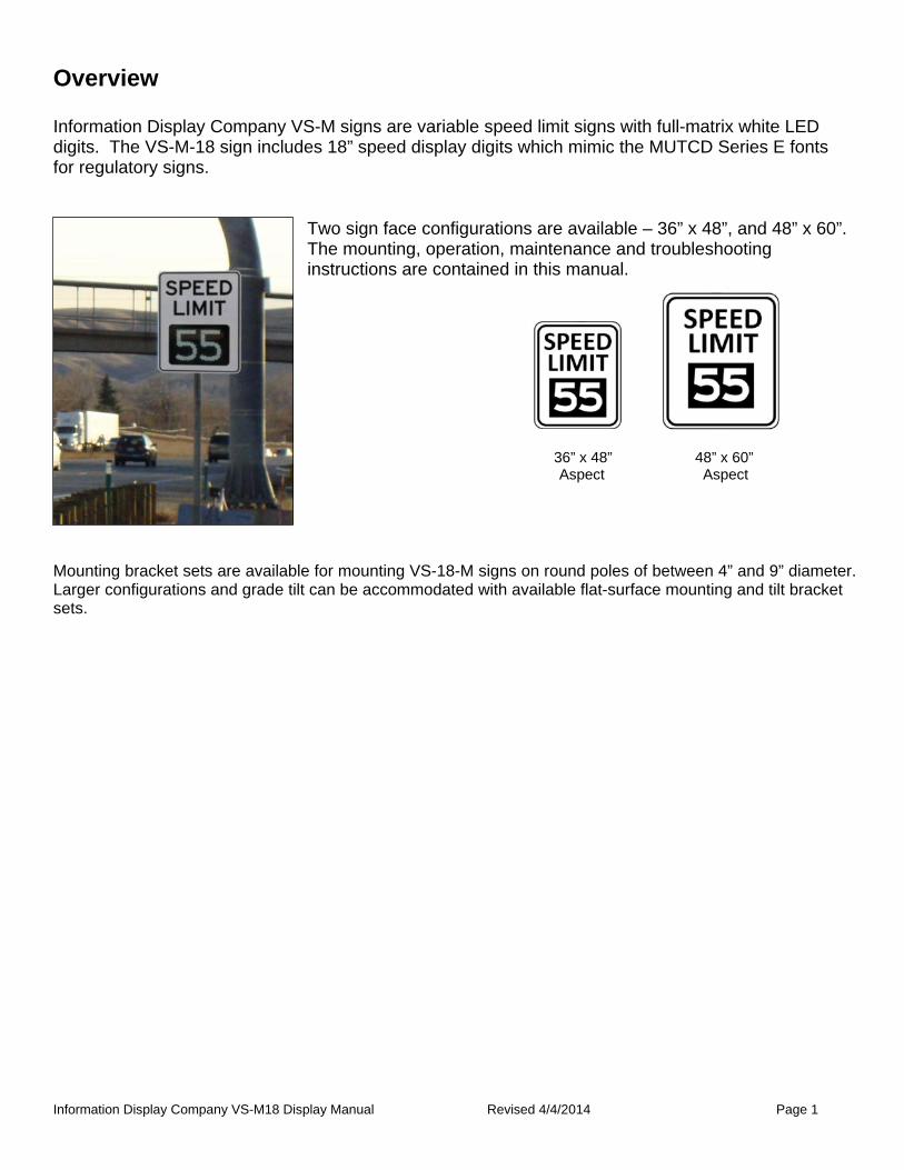
Overview Information Display Company VS-M signs are variable speed limit signs with full-matrix white LED digits. The VS-M-18 sign includes 18” speed display digits which mimic the MUTCD Series E fonts for regulatory signs.
Two sign face configurations are available – 36” x 48”, and 48” x 60”. The mounting, operation, maintenance and troubleshooting instructions are contained in this manual.
Mounting bracket sets are available for mounting VS-18-M signs on round poles of between 4” and 9” diameter. Larger configurations and grade tilt can be accommodated with available flat-surface mounting and tilt bracket sets.
36” x 48” 48” x 60” Aspect Aspect
Information Display Company VS-M18 Display Manual Revised 4/4/2014 Page 2
Required Components Following are the common installation methods and a listing of the components that are required for each method. All components listed as end user supplied are readily available from electrical or traffic control equipment suppliers. Vendor supplied components: Display System:
• VS-M-18 Speed limit sign • AC Systems include pole mounted power supply box w/conduit connectors (see next page) • Sign mounting brackets and fasteners. Attach using ¼-20x ½” button head cap screws • Installation manual
Solar Power Package:
• Solar panel(s) (usually drop-shipped from a solar panel distributor) • Solar panel mounting bracket(s); pole-top mount bracket is standard – pole-side mount is available
for light, telephone or other existing tall poles • Pole mounted solar power box including charge controller and solar battery • Conduit end fittings
RF Communication Package:
• Radio modules, 900MHz internal antenna with Cat-5 POE connection • Pole mounting brackets and attachment screws for radios • ¾” sealed conduit connector for Cat-5 POE cable to connect to sign control board in sign cabinet
Installer supplied components:
• SealTite™ or equivalent conduit in ½” diameter or ¾” diameter (radio uses ¾” diameter) • Stainless steel banding appropriately sized for the installation • Power cabling from the power boxes (AC or solar) to the sign back panel • Cat-5e cable for connecting the radio units to the control boards inside the sign cabinets
AC powered system – general recommendations:
• Frangible or break-away base & hardware if required • Footing materials or foundation for frangible or break-away base if required • Weather head or pole cap • Sign strapping and strap installation tool (see strapping size recommendations on page 6)

Information Display Company VS-M18 Display Manual Revised 4/4/2014 Page 3
Power feed options:
Internal to pole (recommended) The cleanest installation method is to use internal wiring with an entrance fitting going through the side of the pole a foot or two above the sign housing location, on the side of the pole facing the sign. If you contemplate doing this you will also need; • 1 length ¾” conduit for burial as lead-in to pole base • Pole cap • ¾” entrance elbow to be mounted to the pole • Fittings to go from this entrance elbow to the entrance elbow on the sign
External to pole:
The simplest installation by far, and the method most often used, is with the use of external conduit which is strapped to the pole. For this type of installation, in addition to the above, you will also need: • 1 length of ½” conduit suitable for the application • 3 additional bands to attach the conduit to the pole
Pole Mounted AC Power Supply Box
A separate AC power supply enclosure is supplied with 110 volt AC systems. This converts AC power to 12 volts DC needed to operate the sign. Connections and fuses are contained within the enclosure for AC main connection and sign power.
Information Display Company VS-M18 Display Manual Revised 4/4/2014 Page 4
Solar Power System Pole:
• For solar powered installations we recommend the use of at least a 4” pipe size pole. It will provide a solid platform that is capable of withstanding heavy wind loads with solar panels mounted. Based on the specific installation, number and size of solar panels, minimum wind design requirements for your area, local preference, etc., a traffic engineer or traffic control equipment specialist may conclude that something else is more appropriate for your application
• Frangible or break-away base & hardware if required • Footing materials if required • If power is run on outside of pole (as is typically done when installing to existing poles), 2 lengths of
½” conduit suitable for application (recommended IMC or Rigid) • Sign strapping and strap installation tool or heavy-duty tamper proof band clamps • U-bolts cannot be used with pole mounted battery box or Information Display Company side mount
solar racks but can be used with pole top solar panel mounts

Information Display Company VS-M18 Display Manual Revised 4/4/2014 Page 5
AC pole mounted power supply
Solar Powered
Typical Pole Mounting
AC Powered

Information Display Company VS-M18 Display Manual Revised 4/4/2014 Page 6
Sign Mounting The following photos illustrate the assembly of the sign to the pole. The brackets are best when attached to the pole using standard stainless steel sign strapping equipment. The chart on the following page lists the strapping requirements. Hose clamps are ideal for initial temporary installation. They allow easy alignments and adjustment of the various components. Do not use hose clamps for permanent installation.
Strapping provides the most secure and vandal resistant mounting. If you don’t have strapping equipment available, U-bolts can be used.
Strapping size recommendations
¾” x .030” stainless steel band - Single wrap provides adequate strength for 90 MPH wind loading for 36” x 48” sign. For other size sign faces and/or customized installations, consult a design engineer for the appropriate size banding required.

Information Display Company VS-M18 Display Manual Revised 4/4/2014 Page 7
Incorrect
Correct
Roa
dsid
e / F
og L
ine
Dire
cted
tow
ard
onco
min
g tr
affic
200
ft. a
head
Display Viewing
Sign Installation and Alignment Direct the sign into the roadway toward traffic as shown in the illustration; it should aimed at a point 200 ft. ahead of the sign.
Typically, the sign is mounted between 5 feet and 12 feet from the roadside.
Sky Reflections: The sign mounting brackets are designed to provide forward tilt, which prevents reflections of the sun or sky from being seen from a vehicle. The sign viewing angle needs to be in clear view of oncoming traffic with no obstructions, such as trees, signs, buildings, etc. Additional consideration should be made for road curvature.
Mounting brackets are designed to provide forward tilt, which prevents reflections of the sun or sky from being seen from a vehicle
Driver’s line of sight

Information Display Company VS-M18 Display Manual Revised 4/4/2014 Page 8
Solar Panel Installation When installing solar panel(s) always refer to manufacturer specifications for that particular panel(s), or feel free to call Information Display Company for technical assistance. Two panels should be wired in parallel – not in series. Use of a volt meter is always advised to determine proper terminal connection. Open solar panel circuit voltage should generally be between 17 – 22 volts. Typical Solar Power junction box connections are shown here. Exact terminal configuration depends on solar panel model. Black goes to the Negative (-) terminal, Red goes to the Positive (+) terminal. Use a volt meter to test panel output. We find it easier to connect the power cable while the solar panel is still on the ground.
When attaching conduit to the junction box, use caution to put minimum amount of strain on the box. A broken junction box is unrepairable. When a typical pole top mount is used, fully assemble the mounting bracket as shown in the assembly instructions that come with the bracket. Adjust the mounting bracket to fit the solar panel mounting holes (do not mount to panel yet).

Information Display Company VS-M18 Display Manual Revised 4/4/2014 Page 9
After the mounting bracket is assembled and properly set up for your specific solar panels, mount the bracket to the pole without the solar panel(s).
Our experience has shown that it is easier to install the bracket first . Simply lay the solar panel atop the mounting bracket. With the mounting bracket holding most of the weight of the solar panel, easily attach the mounting bolts to hold it in place. This is also safer, in that there is less chance of damaging the solar panel.
Locate the panel rotationally on the pole so that it is directed due TRUE south as opposed to magnetic (compass) south.
NOTE! Make sure to connect the battery to the controller first before connecting the solar panel, or the controller will be damaged and will no longer be usable.
Solar Panel Mounting Angle
Your Latitude Angle From
Horizontal Rise / Run (A/B)
60 77 4.33 55 72 3.08 50 67 2.36 45 62 1.88 40 57 1.54 35 52 1.28 30 47 1.07 25 42 0.90 20 37 0.75
18” signs may have an internal 4 amp fuse located inside the back panel. A 15 amp in-line fuse is used in the cable from the battery to the solar charge controller.
Information Display Company VS-M18 Display Manual Revised 4/4/2014 Page 10
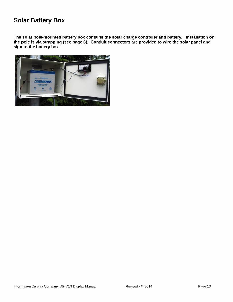
Solar Battery Box
The solar pole-mounted battery box contains the solar charge controller and battery. Installation on the pole is via strapping (see page 6). Conduit connectors are provided to wire the solar panel and sign to the battery box.
Information Display Company VS-M18 Display Manual Revised 4/4/2014 Page 11
Grounding Personal safety and equipment protection depends on adequate grounding. It is extremely important that all components be properly grounded per local electrical code and regional lightning protection, if required, including solar panels and solar power equipment. Use local standard practice to ground the mounting pole, solar power system and panel, and AC power conversion components.
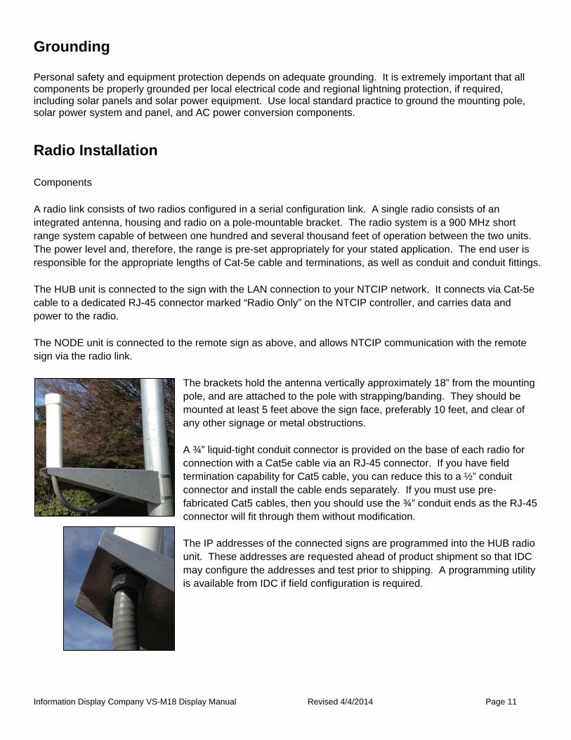
Radio Installation Components A radio link consists of two radios configured in a serial configuration link. A single radio consists of an integrated antenna, housing and radio on a pole-mountable bracket. The radio system is a 900 MHz short range system capable of between one hundred and several thousand feet of operation between the two units. The power level and, therefore, the range is pre-set appropriately for your stated application. The end user is responsible for the appropriate lengths of Cat-5e cable and terminations, as well as conduit and conduit fittings. The HUB unit is connected to the sign with the LAN connection to your NTCIP network. It connects via Cat-5e cable to a dedicated RJ-45 connector marked “Radio Only” on the NTCIP controller, and carries data and power to the radio. The NODE unit is connected to the remote sign as above, and allows NTCIP communication with the remote sign via the radio link.
The brackets hold the antenna vertically approximately 18” from the mounting pole, and are attached to the pole with strapping/banding. They should be mounted at least 5 feet above the sign face, preferably 10 feet, and clear of any other signage or metal obstructions. A ¾” liquid-tight conduit connector is provided on the base of each radio for connection with a Cat5e cable via an RJ-45 connector. If you have field termination capability for Cat5 cable, you can reduce this to a ½” conduit connector and install the cable ends separately. If you must use pre-fabricated Cat5 cables, then you should use the ¾” conduit ends as the RJ-45 connector will fit through them without modification.
The IP addresses of the connected signs are programmed into the HUB radio
unit. These addresses are requested ahead of product shipment so that IDC may configure the addresses and test prior to shipping. A programming utility is available from IDC if field configuration is required.

Information Display Company VS-M18 Display Manual Revised 4/4/2014 Page 12
Installation and Replacement of back panel components
The back panel of the sign contains the main control components. The NTCIP sign controller contains connections for the display boards and the 12VDC power connection. Note that there are two RJ-45 connectors, and one is labeled “Radio Only.” There are one or two conduit connector holes depending on your application. One is for sign power, and the other for the Cat-5 connection to the radio. You can enlarge either or both the holes to accept a ¾” conduit fitting if required. The controller board is protected by a 4A fuse in an inline fuse holder.

Information Display Company VS-M18 Display Manual Revised 4/4/2014 Page 13
Sign Firmware Updating Should the operating system in the NTCIP controller or the sign display panels need updating, the Information Display Company DisplayManager™ software package is used for this purpose. See the separate DisplayManager program guide for specific instructions.
Maintenance Typically the only maintenance required for the VS-M-18 sign is:
1. Ensure the display window is clean 2. Ensure the ventilation ports are not blocked 3. Ensure the solar panel is not obscured by debris or other matter which would block sunlight
4. Check and tighten banding and on U bolts
Information Display Company VS-M18 Display Manual Revised 4/4/2014 Page 14
Troubleshooting 1. Sign does not illuminate
a. Power feed to sign not complete
i. Check solar power battery fuse, wiring
ii. Check AC power fuse, wiring
iii. Check green LED on NTCIP controller is illuminated
b. No message programmed to be on the sign
i. Use a local connection to load a message to the sign
c. Sign damaged such that LEDs are misaligned with front panel windows
i. Replace the sign cabinet
2. Solar system battery depletes during the day
a. System not charging properly
i. Check charge light on the charge controller
ii. Check wiring in solar power battery box
iii. Check wiring to solar panel; should have 17+ volts open circuit at charge controller
iv. Check solar panel aiming; should be pointed true south at correct angle
v. Battery has failed; check for charge performance
3. Sign does not accept network communication
a. Network wiring error or failure
i. Check all connections

Information Display Company VS-M18 Display Manual Revised 4/4/2014 Page 15
Sales, Service and Support You can contact our sales department via email at [email protected] any time or complete our online information request form. We try to answer all email inquiries within 24 hours. Please call us if you have a pressing question.. Web site: http://www.informationdisplay.com/ Information Display Company / SpeedCheck 10950 SW 5th, Suite 330 Beaverton OR 97005 Business hours: Monday through Friday, 8AM–5PM
Phone: 800-421-8325
Fax: 503-626-3417
Email: [email protected]
Information Display Company 10950 SW. 5th, Suite 330
Beaverton OR 97005 (800) 421-8325 Fax
(503) 626-3417