Embed Size (px)
Citation preview

Installation Instructions
Siemens Energy & Automation, Inc. Alpharetta, Georgia U.S.A.
SAFETY INSTRUCTIONS
Instructions for installing commercial meteringFor use with modular metering equipment
and main disconnects
Hazardous Voltage.Will cause death, serious injuryor substantial property damage.
Turn off power supplying thisequipment before working inside.
DANGER
X7519
NOTE: This instruction outlines the recommended installation procedure.
Mount Alignment Rails (Supplied) for Entire Line-up.Determine proper mounting height so that the meter heights in the line-up are in accordance with local codes. (See page 2 Fig. 6 for metering dimensions.)Mount alignment rails for entire line-up as shown in Fig. 1 (Mounting screws supplied by installer).
Prepare Disconnect. Remove the plastic closure plate from side (or sides) of the disconnect which will be joined with the other modules. (Retain cover & hardware for future use.)Install or reposition mounting brackets on each corner on the back of the disconnect as shown in Fig. 2.
Hang Disconnect by slipping the alignment clip over the alignment rail as shown in Fig. 3.
Fig. 1 Alignment Rail Mounting
Wall
Horizontal Line On Wall At Height Determinedon Page 2, Fig. 6
3/8 DiaHoles
AlignmentRails Supplied
ScrewsSupplied ByInstaller
Fig. 3 Detail for Hanging Modular Unit
ModularUnit Wall
Alignment Rail
Alignment Clip
Fig. 2 Detail for Installing Mounting Brackets
Insert Single Bolt Joint into the cross bus opening of the disconnect (See Fig. 4A & 4B). The single bolt joint is supplied in the meter stacks and extension boxes. Single bolt joint not supplied with tap boxes.If needed, order Siemens # SBJ1 (1 Phase) or SBJ4 (3 Phase) single bolt joint or Murray Cat. # DC3 (1 Phase) or DC4 (3 Phase) single bolt joint.
Fig. 4A
Mtg.Bracket
HexHeadBolt
AlignmentClip
Plastic ClosurePlate
Page 1 of 2
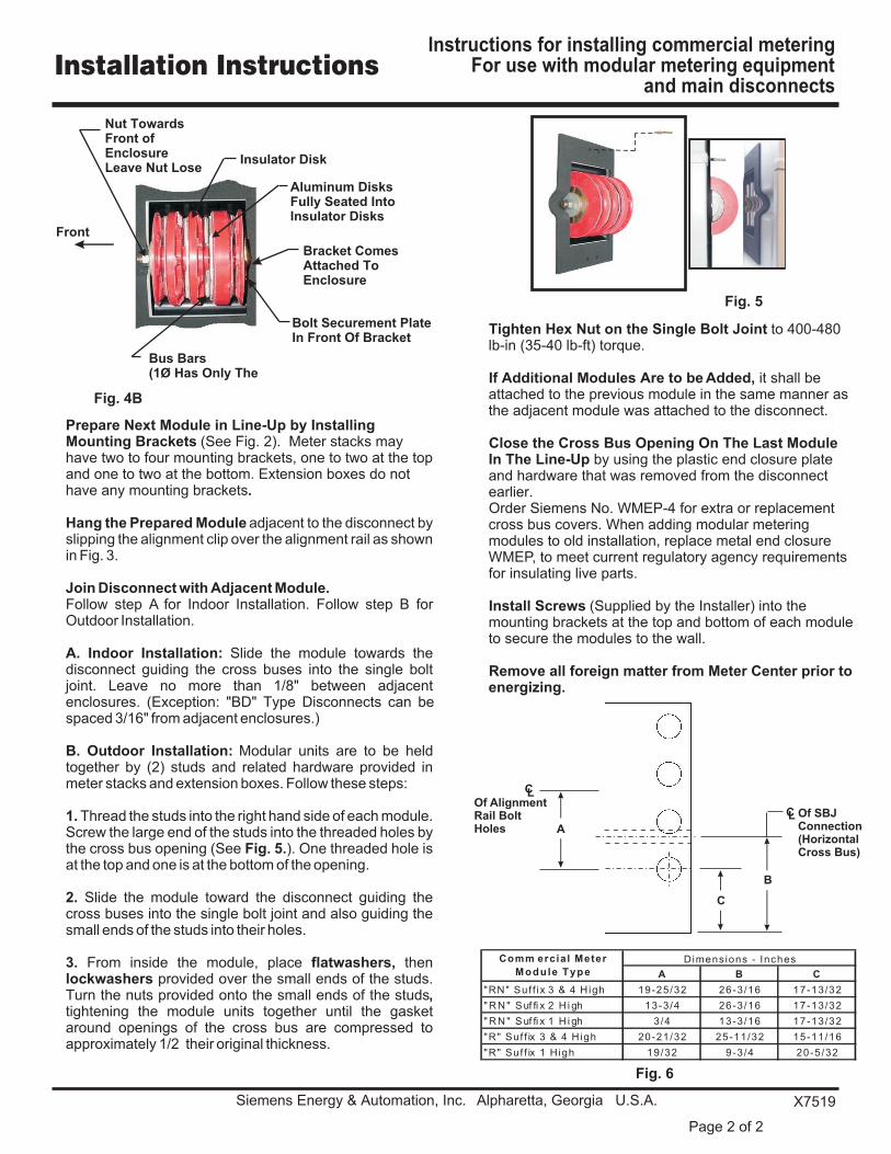
Prepare Next Module in Line-Up by Installing Mounting Brackets (See Fig. 2). Meter stacks may have two to four mounting brackets, one to two at the top and one to two at the bottom. Extension boxes do not have any mounting brackets.
Hang the Prepared Module adjacent to the disconnect by slipping the alignment clip over the alignment rail as shown in Fig. 3.
Join Disconnect with Adjacent Module.Follow step A for Indoor Installation. Follow step B for Outdoor Installation.
A. Indoor Installation: Slide the module towards the disconnect guiding the cross buses into the single bolt joint. Leave no more than 1/8" between adjacent enclosures. (Exception: "BD" Type Disconnects can be spaced 3/16" from adjacent enclosures.)
B. Outdoor Installation: Modular units are to be held together by (2) studs and related hardware provided in meter stacks and extension boxes. Follow these steps:
1. Thread the studs into the right hand side of each module. Screw the large end of the studs into the threaded holes by the cross bus opening (See Fig. 5.). One threaded hole is at the top and one is at the bottom of the opening.
2. Slide the module toward the disconnect guiding the cross buses into the single bolt joint and also guiding the small ends of the studs into their holes.
3. From inside the module, place flatwashers, then lockwashers provided over the small ends of the studs. Turn the nuts provided onto the small ends of the studs, tightening the module units together until the gasket around openings of the cross bus are compressed to approximately 1/2 their original thickness.
Tighten Hex Nut on the Single Bolt Joint to 400-480 lb-in (35-40 lb-ft) torque.
If Additional Modules Are to be Added, it shall be attached to the previous module in the same manner as the adjacent module was attached to the disconnect.
Close the Cross Bus Opening On The Last Module In The Line-Up by using the plastic end closure plate and hardware that was removed from the disconnect earlier.Order Siemens No. WMEP-4 for extra or replacement cross bus covers. When adding modular metering modules to old installation, replace metal end closure WMEP, to meet current regulatory agency requirements for insulating live parts.
Install Screws (Supplied by the Installer) into the mounting brackets at the top and bottom of each module to secure the modules to the wall.
Remove all foreign matter from Meter Center prior to energizing.
Fig. 4B
Fig. 5
Fig. 6
Front
Bolt Securement PlateIn Front Of Bracket
Aluminum DisksFully Seated IntoInsulator Disks
Insulator Disk
Nut TowardsFront of EnclosureLeave Nut Lose
Bracket ComesAttached ToEnclosure
Bus Bars(1 Has Only TheØ
LC
LC Of SBJConnection(Horizontal Cross Bus)
C
B
Of AlignmentRail BoltHoles A
Installation InstructionsInstructions for installing commercial metering
For use with modular metering equipmentand main disconnects
Siemens Energy & Automation, Inc. Alpharetta, Georgia U.S.A. X7519
Page 2 of 2
A B C
"RN" Suf f ix 3 & 4 High 19-25/32 26-3/16 17-13/32
" R N " S uf fi x 2 H i gh 13-3/4 26-3/16 17-13/32
" R N " S uf fi x 1 H i gh 3/4 13-3/16 17-13/32
"R" Suf f ix 3 & 4 High 20-21/32 25-11/32 15-11/16
"R" Suf f ix 1 High 19/32 9-3/4 20-5/32
Dimensions - InchesComm ercial Meter
Module Type


