Embed Size (px)
Citation preview

+49 (0) 8304 / 92933 - 444 · [email protected] · www.sonnenbatterie.de
Installation instructions sonnenBatterie eco 8.2 – for authorised electricians–
KD-228 · Part no. 52187 · Version 1.00

ENIMPORTANT
► Read this documentation carefully before installation.► Retain this document for reference purposes.
Publishersonnen GmbHAm Riedbach 187499 Wildpoldsried, GermanyEmergency hotline +49 (0)83 049 2933 444Email [email protected]
DocumentDocument number KD-228Item number 52187Version 0.12Publication date 22.06.2016
Scope of validityThis document relates to the following product:Product designation sonnenBatterie eco 8.2
page 2 of 57 KD-228 | Part no. 52187 | EN | Version 1.00

Table of contents
Table of contents1 Information about this document.................................................................6
1.1 Target group of this document.............................................................................61.2 Designations in this document............................................................................61.3 Explanation of symbols........................................................................................ 6
2 Safety..............................................................................................................72.1 Intended Use......................................................................................................... 72.2 Requirements for the electrician........................................................................72.3 General safety information................................................................................. 7
2.3.1 Danger due to incorrect operation.............................................................72.3.2 Danger to life due to explosive and flammable materials.......................82.3.3 Danger to life due to product modifications or changes to the product environment.......................................................................................................... 82.3.4 Conduct in case of a fire / Important information for fire services.......8
2.4 Regulations (directives, laws, standards)...........................................................92.5 Warnings............................................................................................................... 9
3 Product description......................................................................................123.1 Technical data...................................................................................................... 123.2 System components.......................................................................................... 133.3 Type plate........................................................................................................... 14
4 Transport and storage.................................................................................144.1 Storage................................................................................................................ 14
4.1.1 Ambient conditions during storage...........................................................144.1.2 Storing the battery modules..................................................................... 14
4.2 Transport............................................................................................................. 154.2.1 Ambient conditions during transport.......................................................154.2.2 Transporting battery modules.................................................................. 154.2.3 Inspecting for transport damage.............................................................154.2.4 Temperature adjustment after transport................................................17
5 Installation....................................................................................................185.1 Scope of delivery................................................................................................. 185.2 Selecting the installation location..................................................................... 19
5.2.1 Requirements for the installation location..............................................195.2.2 Observing minimum distances................................................................. 19
5.3 Opening the doors of the main cabinet........................................................... 195.4 Removing the cover of the extension cabinet...............................................205.5 Removing the filter plates................................................................................ 205.6 Installing the storage system.............................................................................21
KD-228 | Part no. 52187 | EN | Version 1.00 page 3 of 57

Table of contents
5.6.1 Using the correct mounting materials......................................................215.6.2 Placing the levelling mat or the pedestal................................................215.6.3 Drilling the holes...................................................................................... 225.6.4 Mounting the storage system.................................................................23
6 Electrical connection..................................................................................256.1 Working on the electrical distributor................................................................26
6.1.1 Placing components in the distributor.....................................................266.1.2 Wiring components in the electrical distributor.....................................26
6.2 Configurating the power meter........................................................................316.3 Connecting the Ethernet line..........................................................................336.4 Connecting the Modbus line...........................................................................346.5 Connecting the AC supply...............................................................................356.6 Installing the battery modules.........................................................................36
6.6.1 Measuring the battery module voltages..................................................376.6.2 Numbering the battery modules.............................................................376.6.3 Defining the communication addresses.................................................376.6.4 Setting the termination switches............................................................376.6.5 Positioning the battery modules.............................................................386.6.6 Batteriemodule erden..............................................................................396.6.7 Connecting the DC lines........................................................................406.6.8 Connecting the BMS communication line............................................436.6.9 Attaching the fuse plugs..........................................................................456.6.10 Entering the battery capacity/nominal power on the type plate.......45
6.7 Mounting filter plates and cover......................................................................466.7.1 Mounting filter plates............................................................................... 466.7.2 Mounting cover........................................................................................ 47
7 Commissioning............................................................................................487.1 Initial commissioning......................................................................................... 48
7.1.1 Commissioning checklist...........................................................................487.1.2 Commissioning report..............................................................................48
7.2 Switching on the storage system.....................................................................497.2.1 Removing the cover.................................................................................. 497.2.2 Switching on the storage system............................................................49
7.3 Running the commissioning wizard.................................................................507.3.1 Establishing connection to storage system..............................................517.3.2 Running the commissioning wizard.........................................................52
8 Troubleshooting...........................................................................................53
9 Decommissioning........................................................................................54
page 4 of 57 KD-228 | Part no. 52187 | EN | Version 1.00

Table of contents
10 Disposing of the storage system..............................................................54
11 Commissioning report................................................................................57
KD-228 | Part no. 52187 | EN | Version 1.00 page 5 of 57

1 Information about this document
1 Information about this document
This document describes the installation of the sonnenBatterie eco 8.0. Observe the following points:► Read this document in its entirety before beginning the installation work.► Keep this document in the vicinity of the sonnenBatterie.
1.1 Target group of this document
This document is intended for authorised electricians.The actions described here must only be performed by authorised electricians.
1.2 Designations in this document
The following designations are used in this document:
Table 1: Designations in this document
Complete designation Designation in this documentsonnenBatterie eco 8.0 storage system
1.3 Explanation of symbols
Extremely dangerous situation leading to certain death or serious injury if the safety information is not observed.
Dangerous situation leading to potential death or serious injury if the safety information is not observed.
Dangerous situation leading to potential injury if the safety information is not observed.
Indicates actions that may cause material damage.
Important information not associated with any risks to people or property.
Table 2: Additional symbols
Symbol Meaning► Work step1. 2. 3. … Work steps in a defined order
• List
page 6 of 57 KD-228 | Part no. 52187 | EN | Version 1.00
CAUTION
DANGER
WARNING
Notice
CAUTION
DANGER
WARNING
Notice
CAUTION
DANGER
WARNING
Notice
CAUTION
DANGER
WARNING
Notice

Safety 2
2 Safety
2.1 Intended Use
The sonnenBatterie eco 8.0 is a battery storage system which can be used to store electrical energy. Improper use of this system poses a risk of death or injury to the user or third parties as well as damage to the product and other items of value.
The following points must therefore be observed in order to comply with the intended use of the product:• The storage system must be fully installed in accordance with the installation
instructions.• The storage system must be installed by a qualified electrician.• The storage system must only be used at a suitable installation location.• The transport and storage conditions must be observed.
Failure to comply with the conditions of the warranty and the information specified in this document invalidates any warranty claims.
2.2 Requirements for the electrician
The storage system must only be installed and commissioning by authorised electricians. Authorised electricians must meet the following criteria:• The company for which the electrician works must be certified by sonnen
GmbH.• The electrician must be considered competent and registered to work to the UK
national safety standard (BS 7671).• The electrician must have successfully complete sonnen GmbH certification
training for this product.
2.3 General safety information
► Only use the storage system in its original state – without any unauthorised modifications – and when it is in proper working order.► Ensure that all protective devices are working properly.
2.3.1 Danger due to incorrect operation
Incorrect operation puts you and others at risk and could cause material damage.
► Read through these instructions and all further applicable documents carefully, paying special attention to the chapters on safety and warnings.
The device must not be opened during operation.
Manipulating the cabling inside can lead to short circuits/arcs during operation, thus posing a risk of burns and electrocution.
KD-228 | Part no. 52187 | EN | Version 1.00 page 7 of 57

2 Safety
2.3.2 Danger to life due to explosive and flammable materials
► Do not use the storage system in potentially explosive environments.
2.3.3 Danger to life due to product modifications or changes to the product environment
► Never block or bypass the protective devices.► Never modify the protective devices.► Do not make changes to the storage system.► Do not make changes to the electrical and data supply lines.
2.3.4 Conduct in case of a fire / Important information for fire services
Fire may occur with electrical equipment despite its careful design. Likewise, a fire in the vicinity of the equipment can cause the storage system to catch fire, releasing the contents of the battery modules.
► Observe the warnings about the risk of injury/burns due to the escape of electrolyte (see section 2.5 – pg. 9).
In the event of a fire in the vicinity of the product or in the storage system itself, proceed as follows:
► Only firefighters with appropriate protective equipment (safety gloves, safety clothing, face guard, breathing protection) are permitted to enter the room where the burning storage system is located.
There is a danger of electrocution when extinguishing fire while the storage system is switched on. Therefore, before starting to extinguish the fire:► Switch off the storage system.► Switch off the mains fuses in the building.
If the storage system and/or mains fuses cannot be safely switched off:► Observe the minimum distances specified in DIN VDE 0132 for the extinguishing agent used.
The storage system works with an output voltage of 400 V (AC) and is therefore considered a low-voltage system.► A storage system fire can be extinguished using conventional extinguishing agents.► Water is recommended as an extinguishing agent in order to cool the battery modules and therefore prevent thermal runaway in battery modules which are still intact.
Information on the battery modules:• The battery modules have a nominal voltage of 51.2 V (DC) and therefore fall
into the range of protected extra-low voltage (under 60 V DC).• The battery modules do not contain metallic lithium.
page 8 of 57 KD-228 | Part no. 52187 | EN | Version 1.00

Safety 2
Further information can be found in the following document: Merkblatt für Einsatzkräfte – Einsatz an stationären Lithium Solarstromspeichern (Information sheet for electricians – Use on stationary lithium solar energy storage systems, published by the German Solar Association, or BSW – Bundesverband der Solarwirtschaft e.V.)
2.4 Regulations (directives, laws, standards)
► Observe all relevant, currently applicable national regulations, especially the following:
• Regulations of the local power supply companies.This list presents only a selection and does not claim to be exhaustive. The authorised electrician is responsible for knowing and observing all of the regulationsrelevant to their work.
2.5 Warnings
This section contains specific warnings that must always be observed when working with the product.
Danger to life due to electrocution!Touching components inside the storage system poses a danger to life due to electrocution.► Do not touch any components.► Do not remove any plastic covers.► Never reach below covers.
Danger to life due to electrocution!When carrying our electrical work on the storage system, the following must be observed:► Switch off the storage system.► Disconnect the relevant electrical circuits.► Secure against anyone switching on the device again.► Check that the device is disconnected from the power supply.► Only authorised electricians are permitted to carry out electrical work.
Risk of burns!Very high short-circuit currents are possible. The following must be observed when working with the battery modules:The battery module is activated when the fuse connector is plugged in. The voltage runs between the plus and minus contacts of the battery module (nominal
KD-228 | Part no. 52187 | EN | Version 1.00 page 9 of 57
CAUTION
DANGER
WARNING
Notice
CAUTION
DANGER
WARNING
Notice
CAUTION
DANGER
WARNING
Notice

2 Safety
voltage of battery modules: 51.2 V DC). The battery module is deactivated when the fuse connector is unplugged. No voltage runs between the plus and minus contacts of the battery module. If all interconnected battery modules are deactivated, it is safe to work on a battery module.
When working on the DC circuit:► Set aside metal jewellery.► Switch off the storage system.► Switch off the series fuse.► Remove the orange fuse connectors on all battery modules.
page 10 of 57 KD-228 | Part no. 52187 | EN | Version 1.00

Safety 2
Risk of injury and burns due to the escape of electrolyteThe battery modules installed in the storage system are protected by multiple protective devices and can be operated safely.Despite their careful design, the battery cells inside the battery modules may corrode or experience thermal runaway in the event of mechanical damage, heat or a fault.
This can have the following effects:• High heat generation on the surface of the battery cells.• Electrolyte may escape.• The escaping electrolyte may ignite and cause an explosive flame.• The smoke from burning battery modules can irritate the skin, eyes and throat.
Therefore, proceed as follows:► Do not open the battery modules.► Do not mechanically damage the battery modules (pierce, deform, strip down, etc.)► Do not modify the battery modules.► Do not allow the battery modules to come into contact with water (except when extinguishing a fire in the storage system).► Do not heat the battery modules. Operate them only within the permissible temperature range.► Do not short-circuit the battery modules. Do not allow them to come into contact with metal.► Do not continue to use the battery modules after a short circuit.► Do not deep-discharge the battery modules.
In the event that module contents are released:► Do not enter the room under any circumstance.► Avoid contact with the escaping electrolyte.► Contact the fire services.
Damage to battery modules due to deep-discharge!Without a connection to the public electrical mains, the battery modules may be damaged due to being deep-discharged.► Do not disconnect the storage system from the public electrical mains for an extended period of time.
KD-228 | Part no. 52187 | EN | Version 1.00 page 11 of 57
CAUTION
DANGER
WARNING
Notice
CAUTION
DANGER
WARNING
Notice

3 Product description
3 Product description
3.1 Technical datasonnenBatterie eco 8.2/2 eco 8.2/4 eco 8.2/6 eco 8.2/8 eco 8.2/10 eco 8.2/12 eco 8.2/14 eco 8.2/16
System data (AC)Nominal voltage 230 VNominal frequency 50 HzNominal power 1,500 W 2,000 W 2,500 W 2,500 W 2,500 W 2,500 W 2,500 W 2,500 WNominal current 6.5 A 8.7A 13.0 A 13.0 A 13.0 A 13.0 A 13.0 A 13.0 AMains connection single-phase, L / N / PEMains topology TN / TTMains connection fuse miniature circuit breaker | type B | 16 A
Battery data (DC)Cell technology lithium iron phosphate (LiFePO4)Usable capacity 2.0 kWh 4.0 kWh 6.0 kWh 8.0 kWh 10 kWh 12 kWh 14 kWh 16 kWhNominal voltage 51.2 V
Dimensions / weight with small extension cabinet (from 2 kWh up to 10 kWh)Dimensions (H/B/T) in cm 70/64/22 137/64 /22 137/64 /22 137/64 /22 137/64 /22 – – –Weight in kg 53 88 115 142 169 – – –
Dimensions / weight with big extension cabinet (from 2 kWh up to 16 kWh)Dimensions (H/B/T) in cm 70/64/22 184/64 /22 184/64 /22 184/64 /22 184/64 /22 184/64 /22 184/64 /22 184/64 /22Weight in kg 53 93 120 147 174 201 228 255
Power meterVoltage measurement inputs Nominal voltage (AC): 230 V (L-N), 400 V (L-L) | max. connectible conductor cross-section: 1.5 mm2
Clamp-on current transformer Max. measurable current: 60 A
SafetyProtection class I (PE conductor)Degree of protection IP21
Ambient conditionsAmbient temperature range 5°C … 30°CStorage temperature range 0°C … 40°CTransport temperature range -15 °C … 40°CMax. rel. humidity 90%Permissible installation altitude 2000 m above sea levelAdditionalambient conditions • Installation room can be ventilated
• Free from vibrations• Free from dust (especially flour dust or sawdust)• Free from corrosive and explosive gases (ammonia
content max. 20 ppm)
• No direct sunlight• Even floor, suitable for heavy loads• Free access to the installation location• The currently applicable building codes must be
observedTable 3: Technical data
page 12 of 57 KD-228 | Part no. 52187 | EN | Version 1.00

Product description 3
3.2 System componentsFigure 1:
System components
1
XAC
XDIO
S1
F1
XETH
XMOD
2
3
Table 4: System components
No. Designation Function1 Battery inverter Conversion of direct current into alternating current 2 Battery module Storage of electrical power3 Filter plate Holder for filter padF1 fuse switch On/off switch for storage systemXAC AC supply connection Connection to the public electrical mainsXDIO Digital In- and Outputs Interface to emit and receive digital signalsXETH Ethernet port Data connection to router for home networkXMOD Modbus port Data connection to power meterS1 switch Pressed during the switch-on procedure (see section 7.2 –
pg. 49).
KD-228 | Part no. 52187 | EN | Version 1.00 page 13 of 57

3 Product description
3.3 Type plate
The type plate for the storage system is located on the outer surface of the system.The type plate can be used to uniquely identify the storage system. The information on the type plate is required for the safe use of the system and for service matters.
The following information is specified on the type plate:
• Item designation
• Item number
• Version (hardware version)
• Technical data of the storage system
The nominal power and battery capacity of the storage system differ depending on the number of battery modules installed. For this reason the nominal power and battery capacity must be entered on the type plate by the electrician installing the system.
4 Transport and storage
4.1 Storage
Storage describes the condition when the storage system is not connected to the public electrical mains and the battery modules cannot be automatically charged.
4.1.1 Ambient conditions during storage
The ambient conditions specified in Tabular 3 (pg. 12) must be observed during storage.
4.1.2 Storing the battery modules
Damage/destruction of battery modules due to deep-discharge!During storage the battery modules automatically discharge at a minimal level. Deep-discharge could damage or destroy the battery modules. For this reason, the battery modules can only be stored for a limited amount of time.Observe the following points:
• The battery modules must be charged to 85% (charging status upon delivery) when stored.
• Store the battery modules for no longer than 6 months.
• Install the battery modules in the storage system after 6 months at the mostand commission the storage system.
• During storage the orange fuse plug must not be plugged into any battery
page 14 of 57 KD-228 | Part no. 52187 | EN | Version 1.00
CAUTION
DANGER
WARNING
Notice

Transport and storage 4
module.
4.2 Transport
4.2.1 Ambient conditions during transport
The ambient conditions specified in Tabular 3 (pg. 12) must be observed during transport.
4.2.2 Transporting battery modules
Lithium-ion batteries are hazardous goods. Therefore the following points must be observed when transporting the battery modules:► Observe the general transport regulations based on the mode of transport as well as all legal regulations.► Consult an external hazardous goods expert.
The battery module data relevant for transport is provided in the following:• Hazardous goods class: 9• UN number: UN3480 ‘lithium-ion batteries’• Battery module mass (including packaging): 29 kg
4.2.3 Inspecting for transport damage
Danger of injury due to using damaged battery modules!Using damaged battery modules poses risk of releasing hazardous battery contents.► Unpack the battery modules immediately after transport and inspect them for transport damage.If damage (deformation, damage to the housing, release of contents, or similar) is discovered:► Do not use the battery modules under any circumstance.► Notify the service team.
Paragraph 425 of the German Commercial Code (Handelsgesetzbuch) forms the legal basis for processing transport damage. The shipping company can only be held liable for transport damage if it can be proven that the damage occurred during the course of transport. For this reason it is important to follow the instructions given here as closely as possible.
Transport damage is divided into open and hidden damage. Open damage is externally visible damage to the transported goods or their packaging. Hidden damage occurs when the packaging is not damaged but the transported goods inside are.
Open transport damage must be reported to the shipping company immediately. The following timeframes apply in the case of hidden transport damage:
KD-228 | Part no. 52187 | EN | Version 1.00 page 15 of 57
CAUTION
DANGER
WARNING
Notice

4 Transport and storage
• Deutsche Post / DHL / parcel services: report damage within 24 hours
• Shipping company: report damage within 7 daysProceed as follows:
1 Check the shipping documents
dsds► Check the recipient address and number of shipped goods in the presence of theshipper.
2 Inspect the goods for open damage
dsds► Inspect the packaging and transport goods for external damage in the presence of the shipper.
If damage is discovered:► Inspect the goods for hidden damage in the presence of the shipper.
Figure 2: Transport indicator affixed to the
packaging
► Check the transport indicator affixed to the packaging of the main cabinet in the presence of the shipper.
The storage system has not been transported properly if blue powder has been transferred into the arrow of the transport indicator.► Refuse to accept the goods if blue powder has been transferred into the arrow of the transport indicator.
3 Inspect the goods for hidden damage
dsdsThis inspection should also take place in the presence of the shipper if possible.
► Unpack the goods.
► Inspect the goods for hidden (not immediately visible) transport damage.
If transport damage is discovered:► Stop unpacking the product.► Collect photographic evidence of the damage.► Refuse to accept the goods if the discovered defects are serious.
4 Document the defects
dsds► Document the defects identified on the consignment note. The documentation should include the following:• Notation ‘Conditional acceptance’• Registration number of the delivery vehicle• Signature of the shipper
5 Report the damage
dsds► Report the damage to the responsible transport company and the manufacturer
page 16 of 57 KD-228 | Part no. 52187 | EN | Version 1.00

Transport and storage 4
immediately.► Send the consignment note/delivery note with the shipper's confirmation of the damage and photographic evidence to the manufacturer by email.
Damage claims cannot be settled if the abovementioned documentation is not submitted within the stated reporting timeframes.
4.2.4 Temperature adjustment after transport
Damage to the storage system due to condensationIf the temperature of the storage system is lower than the ambient temperature of the room when it is delivered, condensation may form inside the storage system. This may damage the storage system.► Check the inside of the storage system for condensation before installation.► Only install the storage system if there is no condensation on the surfaces.
If the storage system has been transported in sub-zero temperatures,proceed as follows:1. Set up the storage system in a suitable location.2. Open all control cabinet doors.3. Leave the storage system to stand for at least 24 hours with open control cabinet doors.4. Only then can you commission the storage system.
KD-228 | Part no. 52187 | EN | Version 1.00 page 17 of 57
CAUTION
DANGER
WARNING
Notice

5 Installation
5 Installation
5.1 Scope of delivery
► Check the following scope of delivery to ensure it is complete.Abbildung 3:
Scope of delivery1 Scope of delivery for main cabinet2 Scope of delivery for battery
module3 Scope of delivery for big extension
cabinet (up to 16 kWh)4 Scope of delivery for small extension
cabinet (up to 10 kWh)5 Scope of delivery for pedestal
1
2
3
4
453024531245322
11082 11040 20837 20838
21027
KL K
L
KL
1 2 3
KSW
21028600063
45003
20878
1x
3x
1x
2x
1x1x
1x
1x 1x
1x
+49 (0) 8304 / 92933 - 444 · info@s onn e n ba tte rie .de · www.s on n e nba tte rie .de
Installationsanleitung sonnenBatterie eco 8.0 – für Elektrofachkräfte –
+49 (0) 8304 / 92933 - 444 · info@s onn e n ba tte rie .de · www.s on n e nba tte rie .de
Installationsanleitung sonnenBatterie eco 8.0 – für Elektrofachkräfte –
52186 52187
1x 1x1x
A1 A2 N L1 L2 L3
power meter WM 271
StrommessungErzeugung Verbrauch
Current MeasurementGeneration Consumption
Voltage Metering
Spannungsmessung
215121x
1x
1x
45720
453034531345323
113841x
21684
2151521724
5 215442154321545
1x
21724
4x
1x
7x
7x4x
11040 BMS communication line 30 cm 21724 Earth conductor11082 Fuse plug 45003 Battery module11384 RJ45 coupling 45302 Big extension cabinet (color white)20837 DC line red 45312 Big extension cabinet (color black)20838 DC line black 45322 Big extension cabinet (color silver)20878 Sticker numbering for battery modules 45303 Small extension cabinet (color white)21027 Power meter 45313 Small extension cabinet (color black)21028 KSW60-3 current transformer 45323 Small extension cabinet (color silver)21512 Modbus line 45720 Main cabinet (color white)21515 Levelling mat 52186 Operating instructions21543 Pedestal (color black) 52187 Installation instructions21544 Pedestal (color white) 600063 B6 miniature circuit breaker21545 Pedestal (color silver)21684 AC cable
page 18 of 57 KD-228 | Part no. 52187 | EN | Version 1.00

Installation 5
5.2 Selecting the installation location
5.2.1 Requirements for the installation location
► Observe the required ambient conditions (see Table 3: Technical data – pg. 12).
5.2.2 Observing minimum distancesFigure 4:
Minimum distances
50 cm 100 cm
5 cm
15 cm
► Observe the specified minimum distances to neighbouring objects.
The minimum distances ensure that:• there is sufficient heat dissipation,• the storage system door can be
opened easily and• there is sufficient space for
maintenance work.
5.3 Opening the doors of the main cabinetFigure 5: Opening the doors of the
main cabinet► Remove the two Allen screws on theleft side of the main cabinet.
The doors can then be opened.
KD-228 | Part no. 52187 | EN | Version 1.00 page 19 of 57

5 Installation
5.4 Removing the cover of the extension cabinetFigure 6: Removing the cover of the
optional extension cabinetTo remove the cover of the optional extension cabinet:
► Remove the three screws.
► Slide the cover up.
5.5 Removing the filter platesFigure 7: Removing the filter plates
2
1
1
The filter plates of the main and optional extension cabinet can be removed. Removing them makes it easier to install the battery modules later.
► Remove the nuts (1) inside the main and extension cabinet.
► Slide the covers up (2) and take off the cover and place it to the side.
page 20 of 57 KD-228 | Part no. 52187 | EN | Version 1.00
Installation 5
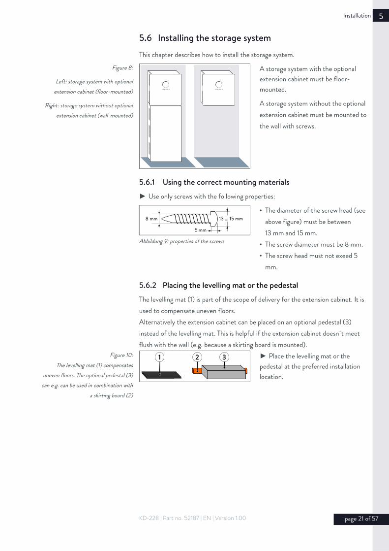
5.6 Installing the storage system
This chapter describes how to install the storage system. Figure 8:
Left: storage system with optionalextension cabinet (floor-mounted)
Right: storage system without optionalextension cabinet (wall-mounted)
A storage system with the optional extension cabinet must be floor-mounted.
A storage system without the optional extension cabinet must be mounted to the wall with screws.
5.6.1 Using the correct mounting materials
► Use only screws with the following properties:
• The diameter of the screw head (see above figure) must be between 13 mm and 15 mm.
• The screw diameter must be 8 mm.• The screw head must not exeed 5
mm.
5.6.2 Placing the levelling mat or the pedestal
The levelling mat (1) is part of the scope of delivery for the extension cabinet. It is used to compensate uneven floors.Alternatively the extension cabinet can be placed on an optional pedestal (3) instead of the levelling mat. This is helpful if the extension cabinet doesn´t meet flush with the wall (e.g. because a skirting board is mounted).
Figure 10:The levelling mat (1) compensates
uneven floors. The optional pedestal (3)can e.g. can be used in combination with
a skirting board (2)
1 32 ► Place the levelling mat or the pedestal at the preferred installation location.
KD-228 | Part no. 52187 | EN | Version 1.00 page 21 of 57
Abbildung 9: properties of the screws
8 mm 13 ... 15 mm
5 mm

5 Installation
5.6.3 Drilling the holes
Holes must be drilled into the wall to mount the storage system. The arrangement of the holes depends on wheather the big or the small extension cabinet is used.
With small extension cabinet (up to 10 kWh)Figure 11: Drill template for storage
systems with small extension cabinet (figure is not to scale – all specifications
are in millimetres)
A Main cabinetB Small extension cabinetC Levelling mat (height: 10 mm) or
pedestal (optional – height: 80 mm)
1610
1532
838,
5
256
65672
3916
1316
524
690
226
33
626
B
A
C
For storage systems consisting of main and small extension cabinet:► Drill the holes shown in red in figure on the left.
► Note that the storage system must be placed on the levelling mat or the pedestal (C).
With big extension cabinet (up to 16 kWh)Figure 12: Drill template for storagesystems with big extension cabinet
(figure is not to scale – all specificationsare in millimetres)
A Main cabinetB Big extension cabinetC Levelling mat (height: 10 mm) or
pedestal (optional – height: 80 mm)
1610
1532
838,
5
402
1142120914
0218
02
52411
76
226
33
626
B
A
C
For storage systems consisting of main and big extension cabinet:► Drill the holes shown in red in figure on the left.
► Note that the storage system must be placed on the levelling mat or the pedestal (C).
Without extension cabinetIf the storage system is used without extension cabinet it is a good idea to observe the dimensions provided in one of the two figures above. That way no new holes need to be drilled if the storage system is extended at a later time.
page 22 of 57 KD-228 | Part no. 52187 | EN | Version 1.00

Installation 5
5.6.4 Mounting the storage system
1 Mount the extension cabinet
Figure 13: Screwing on the extension cabinet
► Mount the extension cabinet (optional) on the wall using suitable screws and dowels (see 5.6.1 – pg. 21).
2 Apply the screws
There are keyhole attachments on the rear of the main cabinet. The main cabinet ismounted using these attachments.
Figure 14: Distance between screw head and wall
2 mm ► Apply suitable screws and anchors (see 5.6.1 – pg. 21) to the previously drilled holes.
The screw should not be completely screwed in. The screw head should protrude from the wall by approx. 2 mm (see above figure).
3 Remove the blind caps
1.Figure 15: Remove the blind caps ► Remove the blind caps.The blind caps are located at the bottom of the main cabinet.
4 Mount the main cabinet
Figure 16: Mounting the main cabinet
► Hang the main cabinet on the previously mounted screws.
KD-228 | Part no. 52187 | EN | Version 1.00 page 23 of 57

5 Installation
5 Tighten the screws
Figure 17: Tightening the screws on the main
cabinet
► Tighten the five screws.
6 Connect the housing
Figure 18: Connecting the housing
An earth conductor is already connected in the extension cabinet.
► Connect the other end of the earth conductor to the earth bolt in the main cabinet.
page 24 of 57 KD-228 | Part no. 52187 | EN | Version 1.00

Electrical connection 6
6 Electrical connection
Danger to life due to electrocution!The following points must be observed when carrying out electrical work on the storage system or on the electrical distributor:► Switch off the storage system.► Disconnect the relevant electrical circuits.► Secure against anyone switching on the device again.► Check that the device is disconnected from the power supply.► Only authorised electricians are permitted to carry out electrical work.
Touch voltage in the event of a faultDanger to life due to electrocution.► Install a residual current device (RCD) in line to the storage system. ► The maximum rated leakage current of the RCD must be 30 mA. The type of the RCD must be adapted to the local conditions. If there are no specific requirements due to the local conditions then a RCD of the type A can be used.
Observe the maximum line lengths.None of the lines connected to the storage system (electrical power, Ethernet line, Modbus line, other data lines, etc.) are allowed to exceed a maximum length of 30 m.
KD-228 | Part no. 52187 | EN | Version 1.00 page 25 of 57
CAUTION
DANGER
WARNING
Notice
CAUTION
DANGER
WARNING
Notice
CAUTION
DANGER
WARNING
Notice

6 Electrical connection
6.1 Working on the electrical distributor
6.1.1 Placing components in the distributor
Several components must be placed in the electrical distributor for the electrical connection of the storage system. Approx. 25 cm of free space on a mounting rail is required for placing the components.► Place the following components in the electrical distributor:
Figure 19: Components to be placed in the
distributor
T
2
A1 A2 13 14 15 16
power meter WM 271
StrommessungErzeugung Verbrauch
Current MeasurementGeneration Consumption
Voltage Metering
Spannungsmessung
1 2 3
KSW
1 2 3
KSW
3 4 51
1 Miniature circuit breaker B16 (not included in scope of delivery)2 WM 271 power meter3 Transformer interfaces4 B6 miniature circuit breaker5 Residual current device (RCD) – 30 mA (not included in scope of delivery)
Explanations for the components:• The miniature circuit breaker (1) protects the connection line to the storage
system.
• The power meter (2) and the transformer interfaces (3) are used to measure the consumption and generation of power in the building.
• The miniature circuit breaker (4) protects the line that is connected to the input for measuring the voltage of the power meter (2).
• The RCD (5) protects against high touch voltage in the event of a fault.
6.1.2 Wiring components in the electrical distributor
► Wire the components previously placed in the electrical distributor like it is shown on the following pages.
page 26 of 57 KD-228 | Part no. 52187 | EN | Version 1.00

Electrical connection 6
Figure 20: Circuit diagram overview – electrical connection at single-phase mains
1 Consumers in building 7 B16 miniature circuit breaker 13 PV inverter miniature circuit breaker2 Transformer interface for consumption (A2) 8 RCD – 30 mA 14 Transformer interface for generation (A2)3 Current transformer for consumption – L1 9 Bidirectional counter 15 Current transformer for production – L14 Current transformer for consumption – L2 10 Public electrical mains 16 Current transformer for production – L25 Current transformer for consumption – L3 11 B6 miniature circuit breaker 17 Current transformer for production – L36 Storage system 12 WM 271 power meter 18 PV inverter
KD-228 | Part no. 52187 | EN | Version 1.00 page 27 of 57
A1A2
1314
1516
pow
er m
eter
W
M 2
71
Stro
mm
essu
ngEr
zeug
ung
Verb
rauc
h
Curre
nt M
easu
rem
ent
Gene
ratio
nCo
nsum
ptio
n
Volta
ge M
eter
ing
Span
nung
smes
sung
kWh
LN
PE
LN
PEL
NPE
T
KL
12
3KSW
KL
KL
KL
1
2
34
5
6 7
8
13
12
11
18
9
10
LN
PE
12
3KSW
14
15
KL
16
KL 17
L
16
->
N
15
->
6 Electrical connection
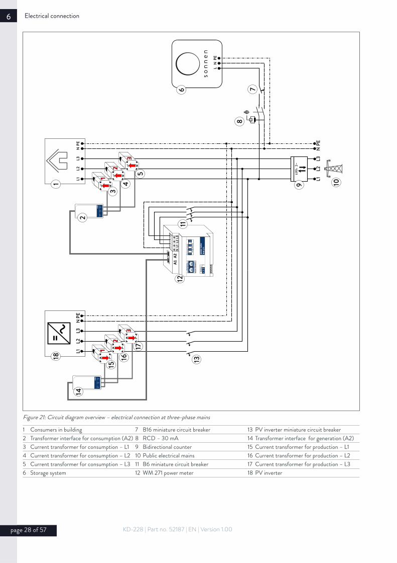
Figure 21: Circuit diagram overview – electrical connection at three-phase mains
1 Consumers in building 7 B16 miniature circuit breaker 13 PV inverter miniature circuit breaker2 Transformer interface for consumption (A2) 8 RCD – 30 mA 14 Transformer interface for generation (A2)3 Current transformer for consumption – L1 9 Bidirectional counter 15 Current transformer for production – L14 Current transformer for consumption – L2 10 Public electrical mains 16 Current transformer for production – L25 Current transformer for consumption – L3 11 B6 miniature circuit breaker 17 Current transformer for production – L36 Storage system 12 WM 271 power meter 18 PV inverter
page 28 of 57 KD-228 | Part no. 52187 | EN | Version 1.00
T
6 7
8
LN
PE
kWh
3~
L1L2
L3N
PE
L1L2
L3N
PEL1
L2L3
NPE
A1A2
NL1
L2L3
KL
KL
KL
12
3KSW
K L
K L
K L
12
3KSW
1
pow
er m
eter
W
M 2
71
Stro
mm
essu
ngEr
zeug
ung
Verb
rauc
h
Curre
nt M
easu
rem
ent
Gene
ratio
nCo
nsum
ptio
n
Volta
ge M
eter
ing
Span
nung
smes
sung
2
3
4
5
13
1211
14
18
15
16
17
9 10
Electrical connection 6
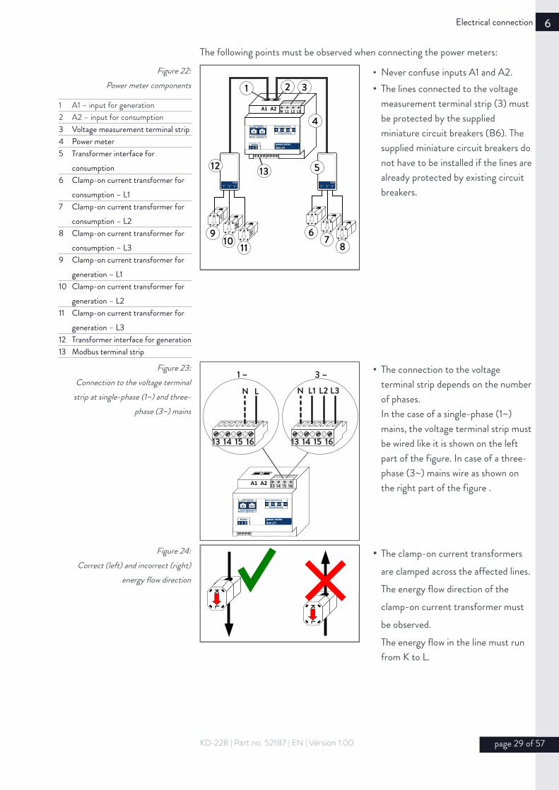
The following points must be observed when connecting the power meters:Figure 22:
Power meter components
1 A1 – input for generation2 A2 – input for consumption3 Voltage measurement terminal strip4 Power meter5 Transformer interface for
consumption6 Clamp-on current transformer for
consumption – L17 Clamp-on current transformer for
consumption – L28 Clamp-on current transformer for
consumption – L39 Clamp-on current transformer for
generation – L110 Clamp-on current transformer for
generation – L211 Clamp-on current transformer for
generation – L312 Transformer interface for generation13 Modbus terminal strip
A1 A2 N L1 L2 L3
KL
KL
KL
KL
KL
1 2 3
KSW
KL
1 2 3
KSW
1 3
4
5
67
8
1312
119
10
2
power meter WM 271
StrommessungErzeugung Verbrauch
Current MeasurementGeneration Consumption
Voltage Metering
Spannungsmessung
• Never confuse inputs A1 and A2.• The lines connected to the voltage
measurement terminal strip (3) must be protected by the supplied miniature circuit breakers (B6). The supplied miniature circuit breakers do not have to be installed if the lines arealready protected by existing circuit breakers.
Figure 23:Connection to the voltage terminal
strip at single-phase (1~) and three-phase (3~) mains
A1 A2 13 14 15 16
power meter WM 271
StrommessungErzeugung Verbrauch
Current MeasurementGeneration Consumption
Voltage Metering
Spannungsmessung
13 14 15 16 13 14 15 16
N L1 L2 L3N L
1 ~ 3 ~ • The connection to the voltage terminal strip depends on the numberof phases.In the case of a single-phase (1~) mains, the voltage terminal strip mustbe wired like it is shown on the left part of the figure. In case of a three-phase (3~) mains wire as shown on the right part of the figure .
Figure 24: Correct (left) and incorrect (right)
energy flow direction
KL K
L
• The clamp-on current transformers are clamped across the affected lines. The energy flow direction of the clamp-on current transformer must be observed.The energy flow in the line must run from K to L.
KD-228 | Part no. 52187 | EN | Version 1.00 page 29 of 57

6 Electrical connection
Figure 25: Connecting the clamp-on current
transformers for three-phase (left) andone-phase generators (right)
1 Clamp-on current transformer for generation L1
2 Clamp-on current transformer for generation L2
3 Clamp-on current transformer for generation L3
4 Transformer interface for generation5 PV inverter or generator
L1 L2 L3 N PE
KL
KL
KL
1 2 3
KSW
L1 N PE
KL
KL K
L
1 2 3
KSW
1
2
3
4
5
1
23
4
5
• In the case of a one-phase PV inverter or a single-phase mains, only the clamp-on current transformer for the phase in question is connected. The other two clamp-on current transformers must not be connected.
Figure 26: Connecting the clamp-on currenttransformers – incorrect (top) and
correct (bottom)
1 2 3KSW
KL
KL
KL
KL
KL
KL
1 2 3KSW
• Do not confuse the phases.Power measurement only works if thecurrent and voltage of the same phase are measured. Example: clamp-on current transformer L1 (marked with number 1) must be connected to phase L1. This phase L1 must also be connected to terminal L1 of the voltage measurement terminal strip. Only then can the correct power for phase L1 be determined.
page 30 of 57 KD-228 | Part no. 52187 | EN | Version 1.00

Electrical connection 6
6.2 Configurating the power meter
The power meter can only work correctly, if the right measuring mode is activated.By default the measuring mode single-phase measurement is activated. In case of athree-phase mains the power meter must therefore be changed to three-phase measurement.
1 Front cover of the power meter2 Clip to remove the front cover
► Press the clips (2) on both sides of the power meter. You might use a small screwdriver.
► Remove the front cover (1).
1 Touch display
► Insert the touch display into the power meter.
► Supply the power meter with energy.
Figure 29: Touch display
► Press for a longer period of time until the password entry screen appears.
Figure 30: password entry screen
► Press for a longer period of time until the CnGPASS screen appears.
Figure 31: CnGPASS screen
► Press once.
The SYS screen appears.
KD-228 | Part no. 52187 | EN | Version 1.00 page 31 of 57
Figure 27: Remove the front cover of the powermeter
1
2
3
4
5
6
A1 A2 N L1 L2 L3
power meter WM 271
StrommessungErzeugung Verbrauch
Current MeasurementGeneration Consumption
Voltage Metering
Spannungsmessung
1
2
Figure 28: Inserting the touch display
1
2
3
4
5
6
A1 A2 N L1 L2 L3
1
1
2
3
4
5
61
2
3
4
5
61
2
3
4
5
6
6 Electrical connection
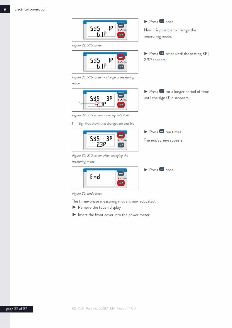
Figure 32: SYS screen
► Press once.
Now it is possible to change the measuring mode.
Figure 33: SYS screen – change of measuring mode
► Press twice until the setting 3P |2.3P appears.
1
2
3
4
5
6
1
Figure 34: SYS screen – setting 3P | 2.3P
1 Sign that shows that changes are possible
► Press for a longer period of time until the sign (1) disappears.
Figure 35: SYS screen after changing the measuring mode
► Press ten times.
The end screen appears.
Figure 36: End screen
► Press once.
The three-phase measuring mode is now activated.► Remove the touch display► Insert the front cover into the power meter.
page 32 of 57 KD-228 | Part no. 52187 | EN | Version 1.00
1
2
3
4
5
61
2
3
4
5
6
1
2
3
4
5
61
2
3
4
5
6

Electrical connection 6
6.3 Connecting the Ethernet line
► Use a patch cable with the following properties as the Ethernet line:• Category: Cat 5 e• Shielded• The patch cable has an angled connector (1). Otherwise it is not possible to close
the cover.
► Connect the patch cable (2) to the Ethernet port (XETH) of the main cabinet.
► Connect the other end of the Ethernet line (2) to the router of the home network (3).
Figure 37:Connecting the Ethernet line to the top
of the main cabinet
1 Angled connector2 Patch cable (not included in
scope of delivery)3 Router of the home networkXETH Ethernet port
XETH
2
3
1
The storage system automatically establishes the connection to the internet once the Ethernet line has been correctly connected.
If the connection to the internet does not establish automatically:
► Follow the instruction in section 8 (S. 53).
KD-228 | Part no. 52187 | EN | Version 1.00 page 33 of 57

6 Electrical connection
6.4 Connecting the Modbus line
Measurement data is transmitted from the power meter to the storage system using the Modbus line.
► Use a patch cable with the following properties as the Modbus line:• Category: Cat 5 e• Shielded• The patch cable has an angled connector (1). Otherwise it is not possible to close
the cover.
► Connect the patch cable (1) as shown in the following figure.Figure 38:
Connecting the Modbus line
1 Angled connector2 Patch cable (not included in
scope of delivery)3 Power meter4 Modbus terminal strip5 Modbus line
A- = white/blueB+ = blueGND = brown
6 RJ45 coupling7 Ports on top of the main cabinetXMOD Modbus port
XMOD
power meter WM 271
StrommessungErzeugung Verbrauch
Current MeasurementGeneration Consumption
Voltage Metering
Spannungsmessung
A1 A2
4
6
5
21 3
7
page 34 of 57 KD-228 | Part no. 52187 | EN | Version 1.00

Electrical connection 6
6.5 Connecting the AC supply
Danger to life due to electrocution!The following points must be observed when carrying out electrical work on the storage system or on the electrical distributor:► Switch off the storage system.► Disconnect the relevant electrical circuits.► Secure against anyone switching on the device again.► Check that the device is disconnected from the power supply.► Only authorised electricians are permitted to carry out electrical work.
► Connect the AC line as shown in the figure below.
Take care of the positioning of the plug (5). Both labels (2) and (3) must face upwards.
► Close the locking device (4).
Abbildung 39: Netzleitung anschließen
1 Top side of the storage system2 Label 3 Label 4 Locking device5 Plug of the AC lineXAC AC supply connection
KD-228 | Part no. 52187 | EN | Version 1.00 page 35 of 57
CAUTION
DANGER
WARNING
Notice
1
XAC
2 3
5
4

6 Electrical connection
6.6 Installing the battery modules
Risk of burns!Very high short-circuit currents are possible. The following must be observed when working with the battery modules:The battery module is activated when the fuse connector is plugged in. The voltage runs between the plus and minus contacts of the battery module (nominalvoltage of battery modules: 51.2 V DC). The battery module is deactivated when the fuse connector is unplugged. No voltage runs between the plus and minus contacts of the battery module. If all interconnected battery modules are deactivated, it is safe to work on a battery module.
When working on the DC circuit:► Set aside metal jewellery.► Switch off the storage system.► Switch off the series fuse.► Remove the orange fuse connectors on all battery modules.
Damage to battery modules due to short circuit!If a short circuit occurs when installing the battery modules despite great care to avoid this, proceed as follows:► Do not install the affected battery modules under any circumstance.► Notify the service team.
page 36 of 57 KD-228 | Part no. 52187 | EN | Version 1.00
CAUTION
DANGER
WARNING
Notice
CAUTION
DANGER
WARNING
Notice

Electrical connection 6
6.6.1 Measuring the battery module voltages
Damage to battery modules due to high compensating currents!Differing battery module voltages lead to high compensating currents when the storage system is switched on.► Measure the voltages between the internal plus and minus poles of all battery modules (see figure below) and note these down.The battery modules are only allowed to be installed if the maximum deviation between the measured voltages is less than 1 V. If the deviation is greater than 1 V:► Notify the service team.
Figure 40: Measuring the battery module voltages
VCOM
V
6.6.2 Numbering the battery modulesFigure 41:
Numbering the battery module
0
► Apply the supplied stickers to the modules.The numbering begins with zero and continues in ascending order.
6.6.3 Defining the communication addressesFigure 42:
Setting the communication addressesusing the rotary switch
0
► Set the communication addresses for the battery modules using the rotary switch.The communication address matches the number of the battery module.
6.6.4 Setting the termination switches
KD-228 | Part no. 52187 | EN | Version 1.00 page 37 of 57
CAUTION
DANGER
WARNING
Notice

6 Electrical connection
Figure 43: Setting the termination switch on the
battery module with the highest number
7
► Slide the termination switch (switch 4) of the battery module with the highest number1 up (switch position ON).
► Ensure that the termination switchesof all other battery modules are in switch position OFF.
6.6.5 Positioning the battery modulesFigure 44:
Positioning the battery modules –without extension cabinet (left) and
with extension cabinet (right)
1
0
0
1
2
3
4
5
6
7
If no extension cabinet is used:► Position the battery module as shown in the left part of the image.
If an extension cabinet is used:► Position the battery modules as shown in the right part of the image.
1 With a sonnenBatterie eco 8/2 this is battery module 0, with a sonnenBatterie eco 8/4 this is battery module 1, and so on... With a sonnenBatterie eco 8/16 this is battery module 7.
page 38 of 57 KD-228 | Part no. 52187 | EN | Version 1.00

Electrical connection 6
6.6.6 Grounding of the battery modulesFigure 45:
Grounding of the battery module in themain cabinet
1 Earth bolt2, 11 Washer3 – 10, 16 Cable lug12 Locking nut13 Earth conductor14 Earth connection of the
battery module15 Socket screw
0
1
2
3
4
5
6
7
1 2 3 4 5 6 7 8 9 1011 12
13
15
1614
► Connect all earthing wires to the earthing pin (1). Take care of the positioning of the components (2) to (12). The cable lugs have to be arranged circularly.
► Tighten the locking nut (12) with a torque of 5 Nm.
► Connect the other end of the earth conductors to the earth connections (14) of the battery modules.
► Tighten the socket screws (15) with atorque of 4 Nm.
KD-228 | Part no. 52187 | EN | Version 1.00 page 39 of 57

6 Electrical connection
6.6.7 Connecting the DC lines
Risk of fire due to high contact resistances and short circuit!Incorrectly connected DC lines can cause a short circuit and thus high heat generation. Improperly connected DC lines can also create high resistance at the point of contact. As very high currents flow through the DC circuit, this high contact resistance can lead to great loss of energy (electrical energy is converted into heat). This can have the following effects:• Cable fire:The area around the affected point of contact is heated above permissible temperatures. A fire breaks out and hazardous substances are released.• Damage to the battery modules:The high contact resistance generates various high battery module loads. Battery modules may be damaged or destroyed by this. Therefore, proceed as follows:► Check all plug connections. Only red lines are allowed to be plugged into red sockets. Only black lines are allowed to be plugged into black sockets.
Figure 46: Correctly connected (top) and
incorrectly connected (bottom) DC line
► Ensure that all DC lines are plugged into the sockets all the way.
Danger to life due to electrocution if DC lines are incorrectly connected!Each battery module has a nominal voltage of 51.2 volts. The battery modules are connected in parallel using the supplied DC lines. The battery modules must neverbe connected in series, as this could result in life-threatening high voltages from the series connection. The high voltage can also lead to damage/destruction of components.► Ensure that all battery modules are connected in parallel, i.e. all plus poles of the battery modules are connected together (red to red). Likewise, ensure that all minus poles of the battery modules are connected together (black to black).
page 40 of 57 KD-228 | Part no. 52187 | EN | Version 1.00
CAUTION
DANGER
WARNING
Notice
CAUTION
DANGER
WARNING
Notice

Electrical connection 6
If no extension cabinet is used:► Connect the DC lines as shown in the figure on the right.
KD-228 | Part no. 52187 | EN | Version 1.00 page 41 of 57
1
0
F1
X1
Figure 47: Connecting the DC lines on the sonnenBatterie eco 8/2 without extension cabinet
6 Electrical connection
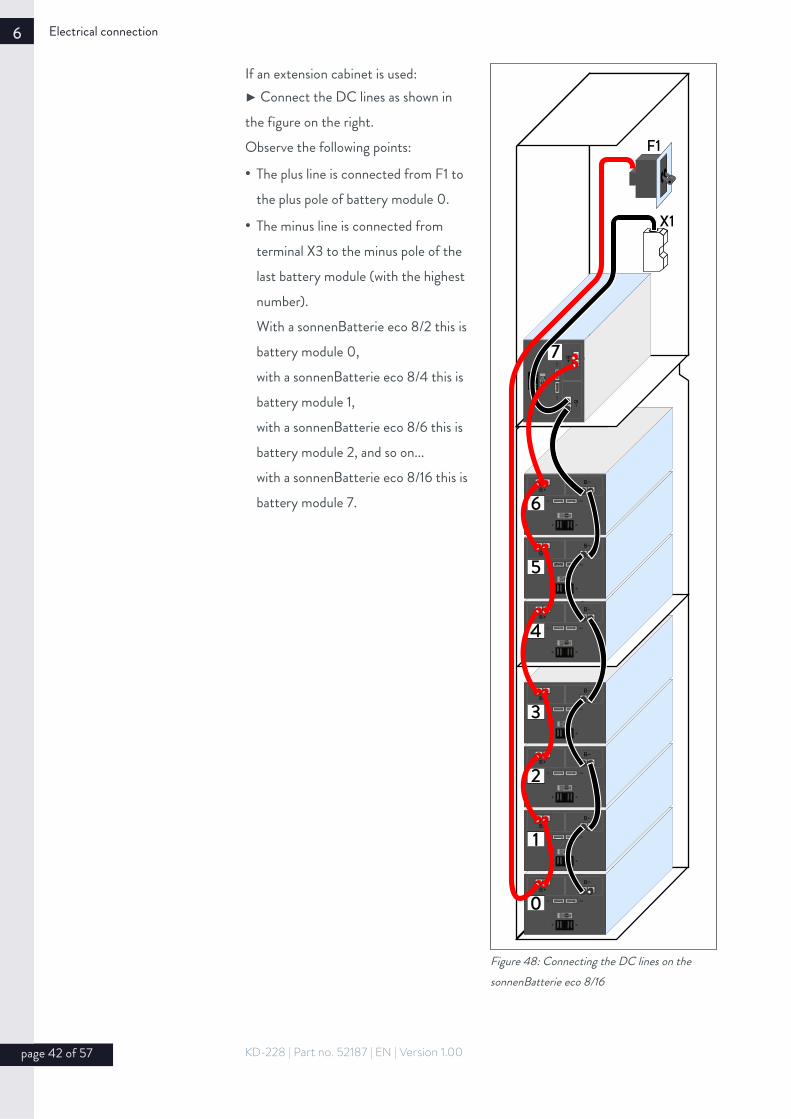
If an extension cabinet is used:► Connect the DC lines as shown in the figure on the right.Observe the following points:
• The plus line is connected from F1 to the plus pole of battery module 0.
• The minus line is connected from terminal X3 to the minus pole of the last battery module (with the highest number). With a sonnenBatterie eco 8/2 this is battery module 0,with a sonnenBatterie eco 8/4 this is battery module 1, with a sonnenBatterie eco 8/6 this is battery module 2, and so on...with a sonnenBatterie eco 8/16 this is battery module 7.
page 42 of 57 KD-228 | Part no. 52187 | EN | Version 1.00
0
1
2
3
4
5
6
7
F1
X1
Figure 48: Connecting the DC lines on the sonnenBatterie eco 8/16

Electrical connection 6
6.6.8 Connecting the BMS communication line
► Connect the BMS lines as shown in the following figures.Use the supplied BMS communication lines.
Figure 49: Connecting the BMS communication
line on the sonnenBatterie eco 8/2
0
Combox
ON
1 2 3 4
KD-228 | Part no. 52187 | EN | Version 1.00 page 43 of 57

6 Electrical connection
Figure 50: Connecting the BMS communication
lines to 8 battery modules
0
1
2
3
4
5
6
Combox
7
ON
1 2 3 4
0
ON
1 2 3 4
0
ON
1 2 3 4
0
ON
1 2 3 4
ON
1 2 3 4
0
ON
1 2 3 4
0
ON
1 2 3 4
0
page 44 of 57 KD-228 | Part no. 52187 | EN | Version 1.00

Electrical connection 6
6.6.9 Attaching the fuse plugs
Prerequisite:✔ All DC lines and BMS communication lines are correctly connected to the battery modules.
► Attach the fuse plugs on all battery modules.
Figure 51: Attaching the fuse plugs
6.6.10 Entering the battery capacity/nominal power on the type plate
Tools:• Permanent marker
► Mark off the correct battery capacity and nominal power on the type plate of the storage system.The type plate is located on the outside of the storage system. The battery capacityand nominal power can be determined from the technical data (see page 12).
KD-228 | Part no. 52187 | EN | Version 1.00 page 45 of 57

6 Electrical connection
6.7 Mounting filter plates and cover
6.7.1 Mounting filter plates
The previously removed filter plates must be reinstalled.Figure 52: Mounting the filter plates 1. Mount the filter plate at the
extension cabinet.
2. Slide the filter plate down, till it is in its end position.
3. Mount the filter plate at the main cabinet.
4. Slide the filter plate down, till it is in its end position.
5. Mount the nuts on the inside of the cabinets.
page 46 of 57 KD-228 | Part no. 52187 | EN | Version 1.00

Electrical connection 6
6.7.2 Mounting coverFigure 53: Mounting the cover of the
extension cabinet► Hook the cover into the front of theextension cabinet.
► Mount the cover with the three screws. Tighten the screws only slightly,making sure that the cover can still be moved.
► Close the door of the main cabinet and align the cover.
► Fully tighten the screws.
KD-228 | Part no. 52187 | EN | Version 1.00 page 47 of 57

7 Commissioning
7 Commissioning
7.1 Initial commissioning
7.1.1 Commissioning checklist
► Check the following points during initial commissioning before switching on the system:
Table 5: Commissioning checklist
OK Points to check□ The installation location meets the requirements.□ All DC lines are completely and correctly connected.□ The Modbus line is correctly connected.□ The Ethernet line is correctly connected.□ The AC supply is correctly connected.□ The AC line meets the requirements of all local and national guidelines for line dimensions.□ The dimensions of the miniature circuit breaker installed in the AC line are correct.□ A residual current device (RCD) has been correctly installed.
7.1.2 Commissioning report
► Complete the commissioning report in the appendix of this document in full.
► Make two copies of the commissioning report.
► Give the first copy to the operator.
► Send the second copy to sonnen GmbH within 5 working days.
page 48 of 57 KD-228 | Part no. 52187 | EN | Version 1.00

Commissioning 7
7.2 Switching on the storage system
To switch on the storage system, the fuse switch F1 and switch S1 must be engaged in a specific order. F1 and S1 are located under the cover at the top side of the storage system.
7.2.1 Removing the cover F1
XMOD1
2
Abbildung 54: Removing the cover (2) at the top side of the storage system
► Remove the knurled nut (1).To do this, rotate the knurled nut (1) counterclockwise.
► Remove the cover (2).
7.2.2 Switching on the storage system
Abbildung 55: Fuse switch F1 and switch S1 at the top side of the storage system
1 Press switch S1 and hold it down while the following steps are carried out.
2 Switch on fuse switch F1.3 Keep switch S1 held down for at
least another 5 seconds.4 Release switch S1.
The storage system then starts up and performs a self-test. Once the self-test is successful, the storage system is ready to operate.
► Mount the previously removed cover.
KD-228 | Part no. 52187 | EN | Version 1.00 page 49 of 57
off off
S1
F1
off

7 Commissioning
7.3 Running the commissioning wizard
With the help of the commissioning wizard the storage system can be configured. The operator as well as the authorised electrician have to enter some informations while the commissioning wizard is running.
The storage system is only ready for operation if the commissioning wizard is fully completed.
page 50 of 57 KD-228 | Part no. 52187 | EN | Version 1.00

Commissioning 7
7.3.1 Establishing connection to storage system
► Connect the laptop (2) to the router of the home network. The storage system must also be connected to the router of the home network.
Figure 56:Ethernet wiring
1 Ethernet line2 Router of the home network3 Ethernet line4 LaptopXETH Ethernet port at the top side of
the storage system
1
43
XETH
1
2
► Start a browser (e.g. Firefox, Chrome, Safari, …) at your laptop.
► Enter the adress finde-meine.sonnenbatterie.de in the adress line of your browser.
https://finde-meine.sonnenbatterie.de
The following window appears:Figure 57: finde-
meine.sonnenbatterie.de
► Click the button Anzeigen.
The login page appears.
If the page finde.meine.sonnenbatterie.de does not appear or the storage system is not displayed:► Follow the instructions in section 8 (S. 53).
KD-228 | Part no. 52187 | EN | Version 1.00 page 51 of 57

7 Commissioning
7.3.2 Running the commissioning wizard
► Select your preferred language from the language selection list (1).
► Select the User Installer from the user selection list (2).
► Enter Sonnen@Installer2016 in the password entry box (3).
► Click the button (4) to confirm your entries.Figure 58: login page
1 Language selection list2 User selection list3 Password entry box4 Confirm button
User
Password
EN DE
User Installer Service Vendor
Anmelden
1
2
43
After that the commissioning wizard will start. ► Run the commissioning wizard until it is fully completed.
page 52 of 57 KD-228 | Part no. 52187 | EN | Version 1.00

Troubleshooting 8
8 Troubleshooting
disturbance reason correctionNo internet connection (the storage system is not displayed at the Internet portal https://meine.sonnenbatterie.de)
• No connection between the storage system and the server.
► Make sure that the Ethernet line between the storage system and the Router of the home network is correctly connected.
► Make sure that the Router of the home network allows connections on the following ports:
TCP-Port Service
22 SecureShell (ssh)
37 Time Server (ntp)
80 Online-Check (http)
222 VPN (Serververbindung ssl)
232 VPN (backup)
443 App-Steuerung (https)
UDP-Port Service
1196 (Serververbindung, ssl)
KD-228 | Part no. 52187 | EN | Version 1.00 page 53 of 57

9 Decommissioning
9 Decommissioning
Damage to battery modules due to deep-discharge!Without a connection to the public electrical mains, the battery modules may be damaged due to being deep-discharged.► Do not disconnect the storage system from the public electrical mains for an extended period of time.
Figure 59: Fuse switch F1 and switch S1 at the top
side of the storage system
off off
S1
F1
► Remove the cover at the top side of the storage system (see chapter 7.2.1 – p. 49).
► Switch off F1.
10 Disposing of the storage systemFigure 60:
WEEE symbolThe storage system and the batteries it contains must not be disposed of as domestic waste.
► Dispose of the storage system and the batteries it contains in an environmentally friendly way through suitable collection systems.
page 54 of 57 KD-228 | Part no. 52187 | EN | Version 1.00
CAUTION
DANGER
WARNING
Notice

Disposing of the storage system 10
KD-228 | Part no. 52187 | EN | Version 1.00 page 55 of 57

sonnen GmbHAm Riedbach 1 D-87499 Wildpoldsried
t +49 ( 0 ) 8304 / 92933 - 444 o info@ sonnenbatterie.de

Commissioning report 11
11 Commissioning report
The completed commissioning report must be sent to the following email address within 5 working days of successful commissioning: [email protected]
Commissioning details
Storage system serial number: Date of commissioning:
Operator details
Surname, first name Street Post code, town
Telephone Email address
Storage system location (only required if location is different from the adress above)
Street Post code, town
Specialist company details
Company Street Post code, town
Telephone Email address
Details on electrician carrying out the work
Name Company Certification number
Details on network topology (mark off the applicable network)
□ TT | □ TN-S | □ TN-C-S | □ TN-C | □ TN-C (classic earthing)
Details on PV system
Feed-in: □ one-phase | □ three-phase Feed-in via phase: □ L1 | □ L2 | □ L3
Nominal power of PV system
Special notes/points to be addressed
Electrician's declaration
I confirm that my details are correct. The storage system was installed and commissioned by me in the proper manner. I followed the installationinstructions in doing so.
Place, date Electrician's signature
Operator's declaration
I confirm that my details are correct.
Place, date Operator's signature
KD-228 | Part no. 52187 | EN | Version 1.00 page 57 of 57