Embed Size (px)
Citation preview

INSTALLATIONINSTRUCTIONS
Single Wall or Double Wall AL29-4C® or 316LSpecial Gas Vent for Category I, II, III and IVTYPE L VENT Low Temperature Venting System (3” to 24”)
3” to 36” Diameter Vent for use on Positive, Neutral and Negative Pressures up to 35” W.C.Also for venting listed gas or oil fired appliances listed for venting with TYPE L low temperature venting system (SSD-SSID ONLY 3” to 24”)
This installation manual will enable you to obtain a safe, efficient and dependable installation of this vent system. Please read and understand these instructions before beginning your installation.Do not alter or modify the components of this chimney system under any circum-stances. Any modification of alteration of the vent system or approved accesso-ries, including but not limited to the appliance it is connected to, may void the warranty, listings and approvals of this system and could result in an unsafe and potentially dangerous installation.A. Examine all components for possible shipping damage prior to installation.B. Proper joint assembly is essential for a safe installation. Follow these instructions exactly as written: Check severeness of joints upon completion of
assembly.C. This venting system must be free to expand and contract. This venting system
must be supported in accordance with these instructions.D. Check for unrestricted vent movement through walls, ceilings, and roof penetrations.E. Different manufacturers have different joint systems and adhesives. Do not mix
pipe, fittings, or joining methods from different manufacturers.
WARNINGSFAILURE TO FOLLOW THESE INSTALLATION INSTRUCTIONS COULD CAUSE FIRE, CARBON MONOXIDE POISONING, OR DEATH. IF YOU ARE UNSURE OF INSTALLA-TION REQUIREMENTS, CALL THE PHONE NUMBER LISTED ON THE BACK OF THESE INSTRUCTIONS.A MAJOR CAUSE OF CHIMNEY RELATED FIRE IS FAILURE TO MAINTAIN REQUIRED CLEARANCES (AIR SPACES) TO COMBUSTIBLE MATERIALS. IT IS OF UTMOST IM-PORTANCE THAT THIS VENT SYSTEM BE INSTALLED ONLY IN ACCORDANCE WITH THESE INSTRUCTIONS
MODEL SS
MODEL SSD MODEL SSID
MODEL LDCS MODEL LDCD
PI SECURESEAL LS474 REV. 15 07-14-17
Listed to standards:UL-1738ULC-S636 Type ‘‘BH’’ ventUL-641 (SSD/SSID ONLY)ULC-S609 (SSD/SSID ONLY)Report # G100215896MTL-006
SAVE THESE INSTRUCTIONS FOR FUTURE REFERENCE
MODEL Secure Seal® SS-SSD-SSID (3” to 24”) LDCS-LDCD (26” to 36”)
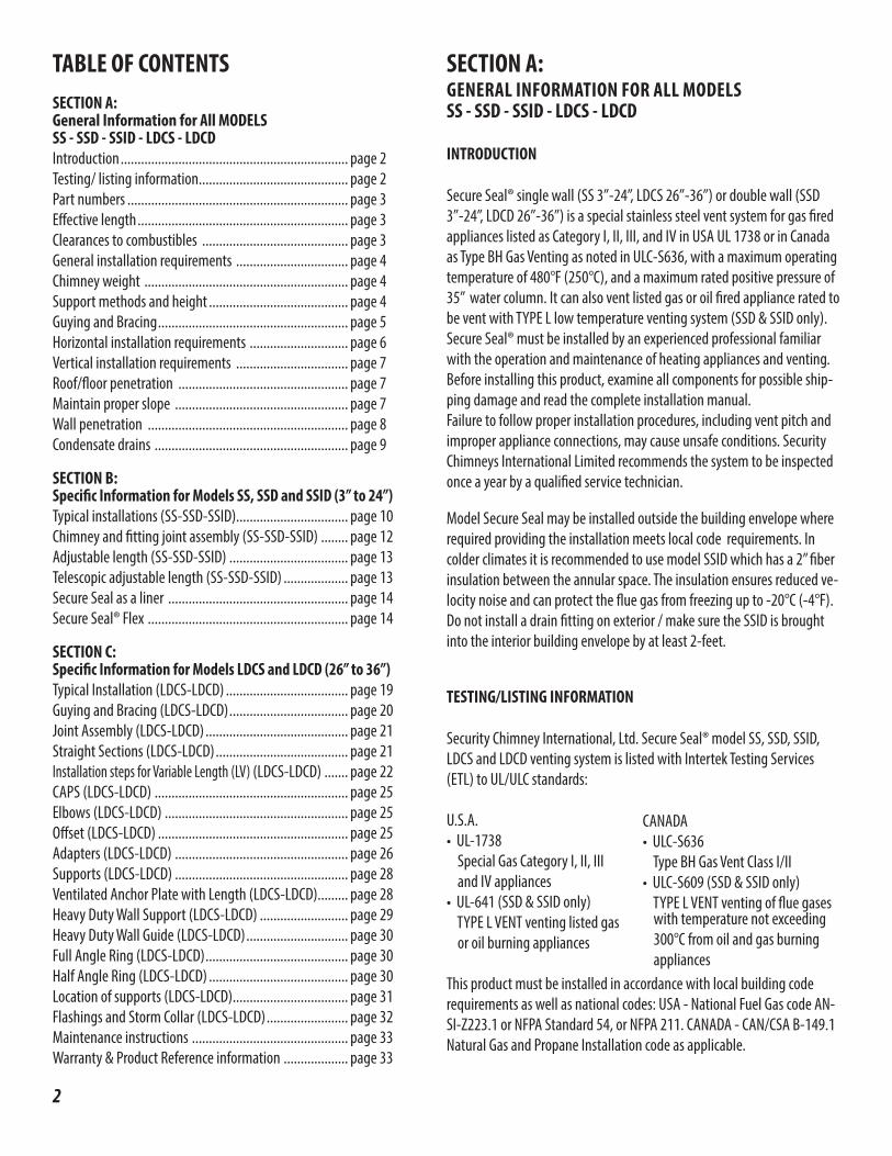
TABLE OF CONTENTSSECTION A: General Information for All MODELS SS - SSD - SSID - LDCS - LDCDIntroduction ................................................................... page 2Testing/ listing information ............................................ page 2Part numbers ................................................................. page 3Effective length .............................................................. page 3Clearances to combustibles ........................................... page 3General installation requirements ................................. page 4Chimney weight ............................................................ page 4Support methods and height ......................................... page 4Guying and Bracing ........................................................ page 5Horizontal installation requirements ............................. page 6Vertical installation requirements ................................. page 7Roof/floor penetration .................................................. page 7Maintain proper slope ................................................... page 7Wall penetration ........................................................... page 8Condensate drains ......................................................... page 9
SECTION B: Specific Information for Models SS, SSD and SSID (3” to 24”)Typical installations (SS-SSD-SSID)................................. page 10Chimney and fitting joint assembly (SS-SSD-SSID) ........ page 12Adjustable length (SS-SSD-SSID) ................................... page 13Telescopic adjustable length (SS-SSD-SSID) ................... page 13Secure Seal as a liner ..................................................... page 14Secure Seal® Flex ........................................................... page 14
SECTION C: Specific Information for Models LDCS and LDCD (26” to 36”) Typical Installation (LDCS-LDCD) .................................... page 19Guying and Bracing (LDCS-LDCD) ................................... page 20Joint Assembly (LDCS-LDCD) .......................................... page 21Straight Sections (LDCS-LDCD) ....................................... page 21Installation steps for Variable Length (LV) (LDCS-LDCD) ....... page 22CAPS (LDCS-LDCD) ......................................................... page 25Elbows (LDCS-LDCD) ...................................................... page 25Offset (LDCS-LDCD) ........................................................ page 25Adapters (LDCS-LDCD) ................................................... page 26Supports (LDCS-LDCD) ................................................... page 28Ventilated Anchor Plate with Length (LDCS-LDCD)......... page 28Heavy Duty Wall Support (LDCS-LDCD) .......................... page 29Heavy Duty Wall Guide (LDCS-LDCD) .............................. page 30Full Angle Ring (LDCS-LDCD) .......................................... page 30Half Angle Ring (LDCS-LDCD) ......................................... page 30Location of supports (LDCS-LDCD) .................................. page 31Flashings and Storm Collar (LDCS-LDCD) ........................ page 32Maintenance instructions .............................................. page 33Warranty & Product Reference information ................... page 33
SECTION A: GENERAL INFORMATION FOR ALL MODELS SS - SSD - SSID - LDCS - LDCD
INTRODUCTION
Secure Seal® single wall (SS 3”-24”, LDCS 26”-36”) or double wall (SSD 3”-24”, LDCD 26”-36”) is a special stainless steel vent system for gas fired appliances listed as Category I, II, III, and IV in USA UL 1738 or in Canada as Type BH Gas Venting as noted in ULC-S636, with a maximum operating temperature of 480°F (250°C), and a maximum rated positive pressure of 35” water column. It can also vent listed gas or oil fired appliance rated to be vent with TYPE L low temperature venting system (SSD & SSID only). Secure Seal® must be installed by an experienced professional familiar with the operation and maintenance of heating appliances and venting. Before installing this product, examine all components for possible ship-ping damage and read the complete installation manual. Failure to follow proper installation procedures, including vent pitch and improper appliance connections, may cause unsafe conditions. Security Chimneys International Limited recommends the system to be inspected once a year by a qualified service technician.
2
Model Secure Seal may be installed outside the building envelope where required providing the installation meets local code requirements. In colder climates it is recommended to use model SSID which has a 2’’ fiber insulation between the annular space. The insulation ensures reduced ve-locity noise and can protect the flue gas from freezing up to -20°C (-4°F). Do not install a drain fitting on exterior / make sure the SSID is brought into the interior building envelope by at least 2-feet.
TESTING/LISTING INFORMATION
Security Chimney International, Ltd. Secure Seal® model SS, SSD, SSID, LDCS and LDCD venting system is listed with Intertek Testing Services (ETL) to UL/ULC standards:
U.S.A.• UL-1738 Special Gas Category I, II, III and IV appliances• UL-641 (SSD & SSID only) TYPE L VENT venting listed gas or oil burning appliances
This product must be installed in accordance with local building code requirements as well as national codes: USA - National Fuel Gas code AN-SI-Z223.1 or NFPA Standard 54, or NFPA 211. CANADA - CAN/CSA B-149.1 Natural Gas and Propane Installation code as applicable.
CANADA• ULC-S636 Type BH Gas Vent Class I/II• ULC-S609 (SSD & SSID only) TYPE L VENT venting of flue gases
with temperature not exceeding 300°C from oil and gas burning appliances
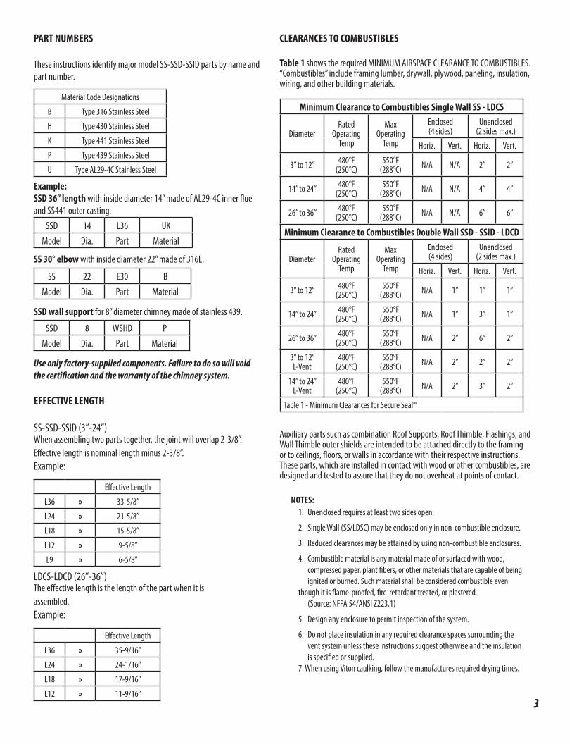
PART NUMBERS
These instructions identify major model SS-SSD-SSID parts by name and part number.
Example:SSD 36” length with inside diameter 14” made of AL29-4C inner flue and SS441 outer casting.
SS 30° elbow with inside diameter 22” made of 316L.
SSD wall support for 8” diameter chimney made of stainless 439.
Use only factory-supplied components. Failure to do so will void the certification and the warranty of the chimney system.
EFFECTIVE LENGTH
SS-SSD-SSID (3”-24”)When assembling two parts together, the joint will overlap 2-3/8”. Effective length is nominal length minus 2-3/8”.Example:
LDCS-LDCD (26”-36”)The effective length is the length of the part when it is assembled.Example:
SSD 14 L36 UKModel Dia. Part Material
SS 22 E30 BModel Dia. Part Material
SSD 8 WSHD PModel Dia. Part Material
Effective Length
L36 » 33-5/8”
L24 » 21-5/8”
L18 » 15-5/8”
L12 » 9-5/8”
L9 » 6-5/8”
Effective Length
L36 » 35-9/16”
L24 » 24-1/16”
L18 » 17-9/16”
L12 » 11-9/16”
CLEARANCES TO COMBUSTIBLES
Table 1 shows the required MINIMUM AIRSPACE CLEARANCE TO COMBUSTIBLES. “Combustibles” include framing lumber, drywall, plywood, paneling, insulation, wiring, and other building materials.
Auxiliary parts such as combination Roof Supports, Roof Thimble, Flashings, and Wall Thimble outer shields are intended to be attached directly to the framing or to ceilings, floors, or walls in accordance with their respective instructions. These parts, which are installed in contact with wood or other combustibles, are designed and tested to assure that they do not overheat at points of contact.
NOTES: 1. Unenclosed requires at least two sides open.
2. Single Wall (SS/LDSC) may be enclosed only in non-combustible enclosure.
3. Reduced clearances may be attained by using non-combustible enclosures.
4. Combustible material is any material made of or surfaced with wood, compressed paper, plant fibers, or other materials that are capable of being ignited or burned. Such material shall be considered combustible even
though it is flame-proofed, fire-retardant treated, or plastered. (Source: NFPA 54/ANSI Z223.1)
5. Design any enclosure to permit inspection of the system.
6. Do not place insulation in any required clearance spaces surrounding the vent system unless these instructions suggest otherwise and the insulation is specified or supplied. 7. When using Viton caulking, follow the manufactures required drying times.
Minimum Clearance to Combustibles Single Wall SS - LDCS
DiameterRated
Operating Temp
MaxOperating
Temp
Enclosed(4 sides)
Unenclosed(2 sides max.)
Horiz. Vert. Horiz. Vert.
3” to 12” 480°F(250°C)
550°F(288°C) N/A N/A 2” 2”
14” to 24” 480°F(250°C)
550°F(288°C) N/A N/A 4” 4”
26” to 36” 480°F(250°C)
550°F(288°C) N/A N/A 6” 6”
Minimum Clearance to Combustibles Double Wall SSD - SSID - LDCD
DiameterRated
Operating Temp
MaxOperating
Temp
Enclosed(4 sides)
Unenclosed(2 sides max.)
Horiz. Vert. Horiz. Vert.
3” to 12” 480°F(250°C)
550°F(288°C) N/A 1” 1” 1”
14” to 24” 480°F(250°C)
550°F(288°C) N/A 1” 3” 1”
26” to 36” 480°F(250°C)
550°F(288°C) N/A 2” 6” 2”
3” to 12”L-Vent
480°F(250°C)
550°F(288°C) N/A 2” 2” 2”
14” to 24”L-Vent
480°F(250°C)
550°F(288°C) N/A 2” 3” 2”
Table 1 - Minimum Clearances for Secure Seal®
3
Material Code Designations
B Type 316 Stainless Steel
H Type 430 Stainless Steel
K Type 441 Stainless Steel
P Type 439 Stainless Steel
U Type AL29-4C Stainless Steel
GENERAL INSTALLATION REQUIREMENTS
When venting Category I, II, III, or IV appliances or TYPE L vented appliance, Secure Seal® must be used for the entire length of the system. Do not mix pipe, fittings, or joining methods from different manufacturers. See the Secure Seal® catalog for a complete list of parts and products. Every vent system must be planned and installed for optimum performance and safety. The venting system must be free to expand and contract and must be supported in accordance with these instructions (Check for unrestricted vent movement through walls, ceilings, and roof penetrations). Refer to the gas appliance manufacturer’s instructions to determine venting requirements and limitations with respect to installation and use of the appliance. It is the responsibility of the installer to contact local building and fire officials concerning any installation restrictions and/or inspection requirements that may apply. Permits may be required before starting an installation.
• If required by the appliance manufacturer, a Drain Tee Cap must be located as close as possible to the appliance flue outlet. Depending on the arrangement of the vent, more than one drain may be required. Unless a Drain Tee Cap is supplied with the appliance, install a Secure Seal® Drain Tee Cap.
• More than one Category II, III, IV appliance may not be connected into the same vent system, unless the appliance manufacturer specifically approved such a system and the appliance are designed for multiple venting. Cat. II, III or IV appliances MAY NOT be common vented with Cat. I, natural draft appliances. This limitation can be removed if an engineering analysis demonstrates normal and safe operation of appliances.
• Secure Seal® must not come in contact with plumbing or electrical systems.
• Maintain rated clearances to combustibles over the entire length of the vent system.
• Secure Seal® shall not be routed into, through, or within any vent, such as an existing masonry or factory-built chimney, that is connected to another appliance.
• Transition parts are available to connect Model SS & SSD to LDCS and LDCD larger size. Refer to Security Chimney’s Technical assistance for guidance.
4
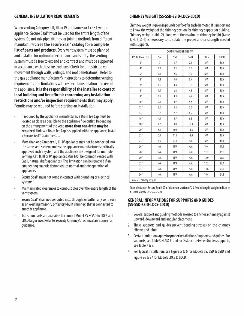
CHIMNEY WEIGHT (SS-SSD-SSID-LDCS-LDCD)
Chimney weight is given in pounds per foot for each diameter. It is important to know the weight of the chimney section for chimney support or guiding. Chimney weight (table 2) along with the maximum chimney height (table 3, 4, 5, & 6) is necessary to calculate the proper anchor strength needed with supports.
CHIMNEY WEIGHT IN LB/FT
INSIDE DIAMETER SS SSD SSID LDCS LDCD
3” .7 1.7 2.1 N/A N/A
4” 0.9 2.1 2.6 N/A N/A
5” 1.1 2.6 3.0 N/A N/A
6” 1.3 3.0 3.4 N/A N/A
7” 1.5 3.4 3.9 N/A N/A
8” 1.7 3.8 4.3 N/A N/A
9” 1.9 4.3 N/A N/A N/A
10” 2.1 4.7 5.5 N/A N/A
12” 2.6 6.2 7.0 N/A N/A
14” 3.6 7.7 8.2 N/A N/A
16” 4.1 8.7 9.3 N/A N/A
18” 4.6 9.8 10.3 N/A N/A
20” 5.1 10.8 11.3 N/A N/A
22” 5.7 11.8 12.4 N/A N/A
24” 6.2 12.8 N/A N/A N/A
26” N/A N/A N/A 10.4 17.9
28” N/A N/A N/A 11.2 19.3
30” N/A N/A N/A 12.0 20.7
32” N/A N/A N/A 12.3 22.1
34” N/A N/A N/A 13.6 23.5
36” N/A N/A N/A 14.4 24.8
Table 2- Chimney weight
Example: Model Secure Seal SSD 6” diameter section of 25 feet in length, weight in lb/ft = 3. Total length 3 x 25 = 75lbs.
GENERAL INFORMATIONS FOR SUPPORTS AND GUIDES (SS-SSD-SSID-LDCS-LDCD)
1. Several support and guiding methods are used to anchor a chimney against upward, downward and angular placement.
2. These supports and guides prevent bending stresses on the chimney elbows and joints.
3. Certain limitations apply for proper installation of supports and guides. For supports, see Table 3, 4, 5 & 6, and for Distance between Guides/supports, see Table 7 & 8.
4. For Typical installation, see Figure 5 & 6 for Models SS, SSD & SSID and Figure 26 & 27 for Models LDCS & LDCD.
5
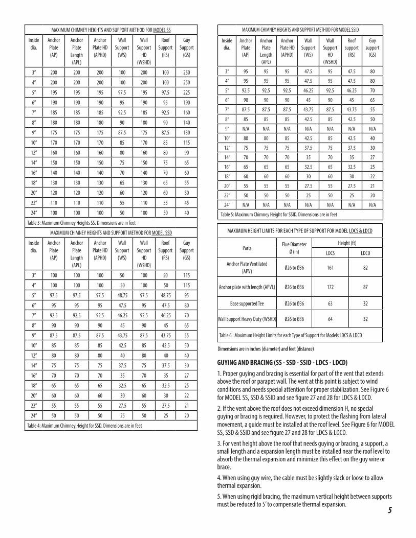
MAXIMUM CHIMNEY HEIGHTS AND SUPPORT METHOD FOR MODEL SS
Inside dia.
Anchor Plate (AP)
Anchor Plate
Length (APL)
Anchor Plate HD (APHD)
Wall Support
(WS)
Wall Support
HD (WSHD)
Roof Support
(RS)
Guy Support
(GS)
3” 200 200 200 100 200 100 250
4” 200 200 200 100 200 100 250
5” 195 195 195 97.5 195 97.5 225
6” 190 190 190 95 190 95 190
7” 185 185 185 92.5 185 92.5 160
8” 180 180 180 90 180 90 140
9” 175 175 175 87.5 175 87.5 130
10” 170 170 170 85 170 85 115
12” 160 160 160 80 160 80 90
14” 150 150 150 75 150 75 65
16” 140 140 140 70 140 70 60
18” 130 130 130 65 130 65 55
20” 120 120 120 60 120 60 50
22” 110 110 110 55 110 55 45
24” 100 100 100 50 100 50 40
Table 3: Maximum Chimney Heights SS. Dimensions are in feet
MAXIMUM CHIMNEY HEIGHTS AND SUPPORT METHOD FOR MODEL SSD
Inside dia.
Anchor Plate (AP)
Anchor Plate
Length (APL)
Anchor Plate HD (APHD)
Wall Support
(WS)
Wall Support
HD (WSHD)
Roof Support
(RS)
Guy Support
(GS)
3” 100 100 100 50 100 50 115
4” 100 100 100 50 100 50 115
5” 97.5 97.5 97.5 48.75 97.5 48.75 95
6” 95 95 95 47.5 95 47.5 80
7” 92.5 92.5 92.5 46.25 92.5 46.25 70
8” 90 90 90 45 90 45 65
9” 87.5 87.5 87.5 43.75 87.5 43.75 55
10” 85 85 85 42.5 85 42.5 50
12” 80 80 80 40 80 40 40
14” 75 75 75 37.5 75 37.5 30
16” 70 70 70 35 70 35 27
18” 65 65 65 32.5 65 32.5 25
20” 60 60 60 30 60 30 22
22” 55 55 55 27.5 55 27.5 21
24” 50 50 50 25 50 25 20
Table 4: Maximum Chimney Height for SSD. Dimensions are in feet
MAXIMUM CHIMNEY HEIGHTS AND SUPPORT METHOD FOR MODEL SSID
Inside dia.
Anchor Plate (AP)
Anchor Plate
Length (APL)
Anchor Plate HD (APHD)
Wall Support
(WS)
Wall Support
HD (WSHD)
Roof support
(RS)
Guy support
(GS)
3” 95 95 95 47.5 95 47.5 80
4” 95 95 95 47.5 95 47.5 80
5” 92.5 92.5 92.5 46.25 92.5 46.25 70
6” 90 90 90 45 90 45 65
7” 87.5 87.5 87.5 43.75 87.5 43.75 55
8” 85 85 85 42.5 85 42.5 50
9” N/A N/A N/A N/A N/A N/A N/A
10” 80 80 85 42.5 85 42.5 40
12” 75 75 75 37.5 75 37.5 30
14” 70 70 70 35 70 35 27
16” 65 65 65 32.5 65 32.5 25
18” 60 60 60 30 60 30 22
20” 55 55 55 27.5 55 27.5 21
22” 50 50 50 25 50 25 20
24” N/A N/A N/A N/A N/A N/A N/A
Table 5: Maximum Chimney Height for SSID. Dimensions are in feet
GUYING AND BRACING (SS - SSD - SSID - LDCS - LDCD)1. Proper guying and bracing is essential for part of the vent that extends above the roof or parapet wall. The vent at this point is subject to wind conditions and needs special attention for proper stabilization. See Figure 6 for MODEL SS, SSD & SSID and see figure 27 and 28 for LDCS & LDCD.2. If the vent above the roof does not exceed dimension H, no special guying or bracing is required. However, to protect the flashing from lateral movement, a guide must be installed at the roof level. See Figure 6 for MODEL SS, SSD & SSID and see figure 27 and 28 for LDCS & LDCD.3. For vent height above the roof that needs guying or bracing, a support, a small length and a expansion length must be installed near the roof level to absorb the thermal expansion and minimize this effect on the guy wire or brace.4. When using guy wire, the cable must be slightly slack or loose to allow thermal expansion.5. When using rigid bracing, the maximum vertical height between supports must be reduced to 5’ to compensate thermal expansion.
MAXIMUM HEIGHT LIMITS FOR EACH TYPE OF SUPPORT FOR MODEL LDCS & LDCD
PartsFlue Diameter
Ø (in)Height (ft)
LDCS LDCD
Anchor Plate Ventilated (APV)
Ø26 to Ø36 161 82
Anchor plate with length (APVL) Ø26 to Ø36 172 87
Base supported Tee Ø26 to Ø36 63 32
Wall Support Heavy Duty (WSHD) Ø26 to Ø36 64 32
Table 6 : Maximum Height Limits for each Type of Support for Models LDCS & LDCD
Dimensions are in inches (diameter) and feet (distance)
6
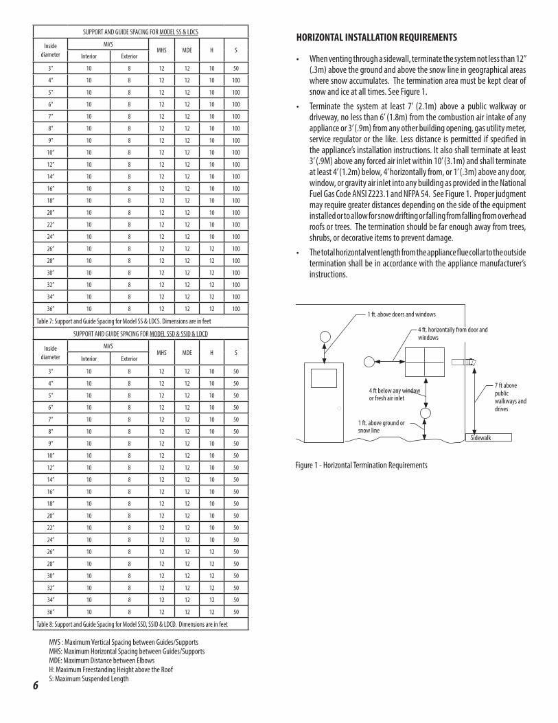
HORIZONTAL INSTALLATION REQUIREMENTS
• When venting through a sidewall, terminate the system not less than 12” (.3m) above the ground and above the snow line in geographical areas where snow accumulates. The termination area must be kept clear of snow and ice at all times. See Figure 1.
• Terminate the system at least 7’ (2.1m) above a public walkway or driveway, no less than 6’ (1.8m) from the combustion air intake of any appliance or 3’ (.9m) from any other building opening, gas utility meter, service regulator or the like. Less distance is permitted if specified in the appliance’s installation instructions. It also shall terminate at least 3’ (.9M) above any forced air inlet within 10’ (3.1m) and shall terminate at least 4’ (1.2m) below, 4’ horizontally from, or 1’ (.3m) above any door, window, or gravity air inlet into any building as provided in the National Fuel Gas Code ANSI Z223.1 and NFPA 54. See Figure 1. Proper judgment may require greater distances depending on the side of the equipment installed or to allow for snow drifting or falling from falling from overhead roofs or trees. The termination should be far enough away from trees, shrubs, or decorative items to prevent damage.
• The total horizontal vent length from the appliance flue collar to the outside termination shall be in accordance with the appliance manufacturer’s instructions.
MVS : Maximum Vertical Spacing between Guides/SupportsMHS: Maximum Horizontal Spacing between Guides/SupportsMDE: Maximum Distance between ElbowsH: Maximum Freestanding Height above the RoofS: Maximum Suspended Length
SUPPORT AND GUIDE SPACING FOR MODEL SS & LDCS
Inside diameter
MVSMHS MDE H S
Interior Exterior
3” 10 8 12 12 10 50
4” 10 8 12 12 10 100
5” 10 8 12 12 10 100
6” 10 8 12 12 10 100
7” 10 8 12 12 10 100
8” 10 8 12 12 10 100
9” 10 8 12 12 10 100
10” 10 8 12 12 10 100
12” 10 8 12 12 10 100
14” 10 8 12 12 10 100
16” 10 8 12 12 10 100
18” 10 8 12 12 10 100
20” 10 8 12 12 10 100
22” 10 8 12 12 10 100
24” 10 8 12 12 10 100
26” 10 8 12 12 12 100
28” 10 8 12 12 12 100
30” 10 8 12 12 12 100
32” 10 8 12 12 12 100
34” 10 8 12 12 12 100
36” 10 8 12 12 12 100
Table 7: Support and Guide Spacing for Model SS & LDCS. Dimensions are in feet
SUPPORT AND GUIDE SPACING FOR MODEL SSD & SSID & LDCD
Inside diameter
MVSMHS MDE H S
Interior Exterior
3” 10 8 12 12 10 50
4” 10 8 12 12 10 50
5” 10 8 12 12 10 50
6” 10 8 12 12 10 50
7” 10 8 12 12 10 50
8” 10 8 12 12 10 50
9” 10 8 12 12 10 50
10” 10 8 12 12 10 50
12” 10 8 12 12 10 50
14” 10 8 12 12 10 50
16” 10 8 12 12 10 50
18” 10 8 12 12 10 50
20” 10 8 12 12 10 50
22” 10 8 12 12 10 50
24” 10 8 12 12 10 50
26” 10 8 12 12 12 50
28” 10 8 12 12 12 50
30” 10 8 12 12 12 50
32” 10 8 12 12 12 50
34” 10 8 12 12 12 50
36” 10 8 12 12 12 50
Table 8: Support and Guide Spacing for Model SSD, SSID & LDCD. Dimensions are in feet
7 ft above public walkways and drives
1 ft. above doors and windows
4 ft below any window or fresh air inlet
1 ft. above ground or snow line
Sidewalk
Figure 1 - Horizontal Termination Requirements
4 ft. horizontally from door and windows
7Figure 2- Vertical Installation Requirements
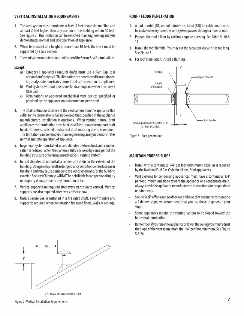
MAINTAIN PROPER SLOPE
• Install with a continuous 1/4” per foot (minimum) slope, as is required by the National Fuel Gas Code for all gas-fired appliances.
• Vent systems for condensing appliances must have a continuous 1/4” per foot (minimum) slope toward the appliance or a condensate drain. Always check the appliance manufacturer’s instructions for proper drain requirements.
• Secure Seal® offers a range of tees and elbows that are built incorporating a 2 degree slope, we recommend that you use these to generate your slope.
• Some appliances require the venting system to be sloped toward the horizontal termination.
• Remember, if you raise the appliance or lower the ceiling you must adjust the slope of the vent to maintain the 1/4” per foot minimum. See Figure 5 & 26.
VERTICAL INSTALLATION REQUIREMENTS
1. The vent system must terminate at least 3 feet above the roof line and at least 2 feet higher than any portion of the building within 10 feet. See Figure 2. This limitation can be removed if an engineering analysis demonstrates normal and safe operation of appliance.
2. When terminated at a height of more than 10 feet, the stack must be supported by a Guy Section.
3. The vent system must terminate with one of the Secure Seal® terminations.
Except; a) Category I appliances (natural draft) must use a Rain Cap. It is
optional on Category II. This limitation can be removed if an engineer-ing analysis demonstrates normal and safe operation of appliance.
b) Vent systems without provisions for draining rain water must use a Rain Cap.
c) Terminations or approved mechanical vent devices specified or provided by the appliance manufacturer are permitted.
4. The total continuous distance of the vent system from the appliance flue collar to the termination shall not exceed that specified in the appliance manufacturer’s installation instructions. When venting natural draft appliances the termination must be at least 5 feet above the topmost draft hood. Otherwise a listed mechanical draft inducing device is required. This limitation can be removed if an engineering analysis demonstrates normal and safe operation of appliance.
5. In general, systems installed in cold climates perform best, and conden-sation is reduced, when the system is fully enclosed by some part of the building structure or by using insulated SSID venting system.
6. In cold climates do not install a condensate drain on the exterior of the building. Doing so may result in dangerous icy conditions on surfaces near the drain and may cause damage to the vent system and/or the building exterior. Security Chimneys will NOT be held liable for any personal injury or property damage due to any formation of ice.
7. Vertical supports are required after every transition to vertical. Vertical supports are also required after every offset elbow.
8. Unless Secure Seal is installed in a fire rated shaft, a roof thimble and support is required when penetration fire rated floors, walls or ceilings.
2 ft. above structures within 10 ft.
10’
2’
ROOF / FLOOR PENETRATION
1. A roof thimble (RT) or roof thimble insulated (RTI) for cold climate must be installed every time the vent system passes through a floor or roof.
2. Prepare the roof / floor by cutting a square opening. See Table 9, 10 & 11.
3. Install the roof thimble. You may cut the radiation sleeve if it is too long. See Figure 3.
4. For roof installation, install a flashing.
Support or Guide
Roof thimbleOpening dimension See Table 9, 10
& 11 for all Models
Air gap or insulated
Flashing
Figure 3 - Roof penetration
8
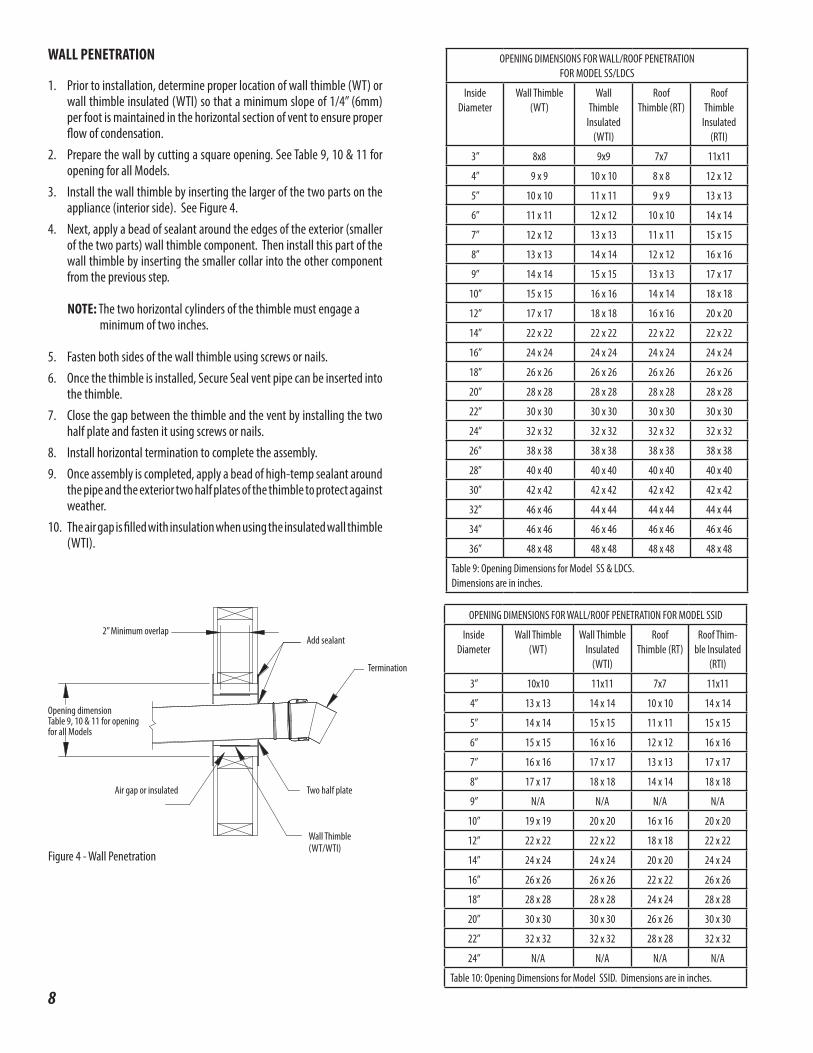
Figure 4 - Wall Penetration
Wall Thimble(WT/WTI)
Air gap or insulated Two half plate
Termination
Add sealant
Opening dimensionTable 9, 10 & 11 for opening for all Models
2” Minimum overlap
WALL PENETRATION
1. Prior to installation, determine proper location of wall thimble (WT) or wall thimble insulated (WTI) so that a minimum slope of 1/4” (6mm) per foot is maintained in the horizontal section of vent to ensure proper flow of condensation.
2. Prepare the wall by cutting a square opening. See Table 9, 10 & 11 for opening for all Models.
3. Install the wall thimble by inserting the larger of the two parts on the appliance (interior side). See Figure 4.
4. Next, apply a bead of sealant around the edges of the exterior (smaller of the two parts) wall thimble component. Then install this part of the wall thimble by inserting the smaller collar into the other component from the previous step.
NOTE: The two horizontal cylinders of the thimble must engage a minimum of two inches.
5. Fasten both sides of the wall thimble using screws or nails.6. Once the thimble is installed, Secure Seal vent pipe can be inserted into
the thimble.7. Close the gap between the thimble and the vent by installing the two
half plate and fasten it using screws or nails.8. Install horizontal termination to complete the assembly.9. Once assembly is completed, apply a bead of high-temp sealant around
the pipe and the exterior two half plates of the thimble to protect against weather.
10. The air gap is filled with insulation when using the insulated wall thimble (WTI).
OPENING DIMENSIONS FOR WALL/ROOF PENETRATION FOR MODEL SSID
Inside Diameter
Wall Thimble (WT)
Wall Thimble Insulated
(WTI)
Roof Thimble (RT)
Roof Thim-ble Insulated
(RTI)
3” 10x10 11x11 7x7 11x11
4” 13 x 13 14 x 14 10 x 10 14 x 14
5” 14 x 14 15 x 15 11 x 11 15 x 15
6” 15 x 15 16 x 16 12 x 12 16 x 16
7” 16 x 16 17 x 17 13 x 13 17 x 17
8” 17 x 17 18 x 18 14 x 14 18 x 18
9” N/A N/A N/A N/A
10” 19 x 19 20 x 20 16 x 16 20 x 20
12” 22 x 22 22 x 22 18 x 18 22 x 22
14” 24 x 24 24 x 24 20 x 20 24 x 24
16” 26 x 26 26 x 26 22 x 22 26 x 26
18” 28 x 28 28 x 28 24 x 24 28 x 28
20” 30 x 30 30 x 30 26 x 26 30 x 30
22” 32 x 32 32 x 32 28 x 28 32 x 32
24” N/A N/A N/A N/A
Table 10: Opening Dimensions for Model SSID. Dimensions are in inches.
OPENING DIMENSIONS FOR WALL/ROOF PENETRATIONFOR MODEL SS/LDCS
Inside Diameter
Wall Thimble (WT)
Wall Thimble
Insulated (WTI)
Roof Thimble (RT)
Roof Thimble
Insulated (RTI)
3” 8x8 9x9 7x7 11x11
4” 9 x 9 10 x 10 8 x 8 12 x 12
5” 10 x 10 11 x 11 9 x 9 13 x 13
6” 11 x 11 12 x 12 10 x 10 14 x 14
7” 12 x 12 13 x 13 11 x 11 15 x 15
8” 13 x 13 14 x 14 12 x 12 16 x 16
9” 14 x 14 15 x 15 13 x 13 17 x 17
10” 15 x 15 16 x 16 14 x 14 18 x 18
12” 17 x 17 18 x 18 16 x 16 20 x 20
14” 22 x 22 22 x 22 22 x 22 22 x 22
16” 24 x 24 24 x 24 24 x 24 24 x 24
18” 26 x 26 26 x 26 26 x 26 26 x 26
20” 28 x 28 28 x 28 28 x 28 28 x 28
22” 30 x 30 30 x 30 30 x 30 30 x 30
24” 32 x 32 32 x 32 32 x 32 32 x 32
26” 38 x 38 38 x 38 38 x 38 38 x 38
28” 40 x 40 40 x 40 40 x 40 40 x 40
30” 42 x 42 42 x 42 42 x 42 42 x 42
32” 46 x 46 44 x 44 44 x 44 44 x 44
34” 46 x 46 46 x 46 46 x 46 46 x 46
36” 48 x 48 48 x 48 48 x 48 48 x 48
Table 9: Opening Dimensions for Model SS & LDCS.Dimensions are in inches.
9
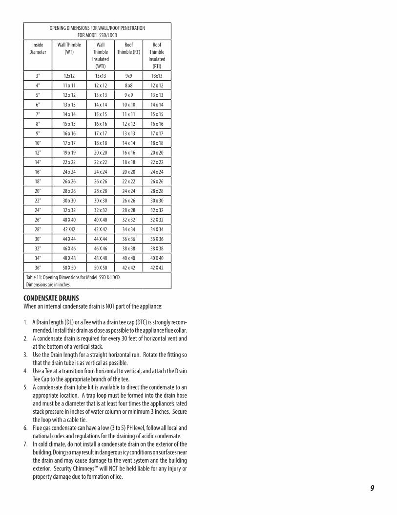
OPENING DIMENSIONS FOR WALL/ROOF PENETRATIONFOR MODEL SSD/LDCD
Inside Diameter
Wall Thimble (WT)
Wall Thimble
Insulated (WTI)
Roof Thimble (RT)
Roof Thimble
Insulated (RTI)
3” 12x12 13x13 9x9 13x13
4” 11 x 11 12 x 12 8 x8 12 x 12
5” 12 x 12 13 x 13 9 x 9 13 x 13
6” 13 x 13 14 x 14 10 x 10 14 x 14
7” 14 x 14 15 x 15 11 x 11 15 x 15
8” 15 x 15 16 x 16 12 x 12 16 x 16
9” 16 x 16 17 x 17 13 x 13 17 x 17
10” 17 x 17 18 x 18 14 x 14 18 x 18
12” 19 x 19 20 x 20 16 x 16 20 x 20
14” 22 x 22 22 x 22 18 x 18 22 x 22
16” 24 x 24 24 x 24 20 x 20 24 x 24
18” 26 x 26 26 x 26 22 x 22 26 x 26
20” 28 x 28 28 x 28 24 x 24 28 x 28
22” 30 x 30 30 x 30 26 x 26 30 x 30
24” 32 x 32 32 x 32 28 x 28 32 x 32
26” 40 X 40 40 X 40 32 x 32 32 X 32
28” 42 X42 42 X 42 34 x 34 34 X 34
30” 44 X 44 44 X 44 36 x 36 36 X 36
32” 46 X 46 46 X 46 38 x 38 38 X 38
34” 48 X 48 48 X 48 40 x 40 40 X 40
36” 50 X 50 50 X 50 42 x 42 42 X 42
Table 11: Opening Dimensions for Model SSD & LDCD. Dimensions are in inches.
CONDENSATE DRAINSWhen an internal condensate drain is NOT part of the appliance:
1. A Drain length (DL) or a Tee with a drain tee cap (DTC) is strongly recom-mended. Install this drain as close as possible to the appliance flue collar.
2. A condensate drain is required for every 30 feet of horizontal vent and at the bottom of a vertical stack.
3. Use the Drain length for a straight horizontal run. Rotate the fitting so that the drain tube is as vertical as possible.
4. Use a Tee at a transition from horizontal to vertical, and attach the Drain Tee Cap to the appropriate branch of the tee.
5. A condensate drain tube kit is available to direct the condensate to an appropriate location. A trap loop must be formed into the drain hose and must be a diameter that is at least four times the appliance’s rated stack pressure in inches of water column or minimum 3 inches. Secure the loop with a cable tie.
6. Flue gas condensate can have a low (3 to 5) PH level, follow all local and national codes and regulations for the draining of acidic condensate.
7. In cold climate, do not install a condensate drain on the exterior of the building. Doing so may result in dangerous icy conditions on surfaces near the drain and may cause damage to the vent system and the building exterior. Security Chimneys™ will NOT be held liable for any injury or property damage due to formation of ice.
10
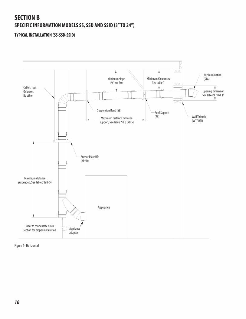
TYPICAL INSTALLATION (SS-SSD-SSID)
Cables, rodsOr bracesBy other
Minimum slope1/4” per foot
Minimum ClearancesSee table 1
Maximum distance betweensupport, See Table 7 & 8 (MHS)
30º Termination(STA)
Opening dimensionSee Table 9, 10 & 11
Wall Thimble(WT/WTI)
Roof Support (RS)
Suspension Band (SB)
Anchor Plate HD(APHD)
Appliance
Maximum distance suspended, See Table 7 & 8 (S)
Figure 5- Horizontal
Refer to condensate drain section for proper installation Appliance
adaptor
SECTION BSPECIFIC INFORMATION MODELS SS, SSD AND SSID (3” TO 24”)
11
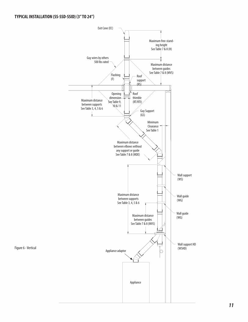
TYPICAL INSTALLATION (SS-SSD-SSID) (3” TO 24”)
Exit Cone (EC)
Guy wires by others500 lbs rated
Flashing(F)
Roofsupport(RS)
Guy Support(GS)
Wall guide(WG)
Wall guide(WG)
Wall support HD(WSHD)
Appliance
Wall support(WS)
Roofthimble(RT/RTI)
Maximum distancebetween guides
See Table 7 & 8 (MVS)
Opening dimension
See Table 9, 10 & 11
MinimumClearance
See Table 1
Maximum distancebetween supports
See Table 3, 4, 5 & 6
Maximum distancebetween elbows without
any support or guideSee Table 7 & 8 (MDE)
Maximum distancebetween guides
See Table 7 & 8 (MVS)
Maximum distancebetween supports
See Table 3, 4, 5 & 6
Maximum free-stand-ing height
See Table 7 & 8 (H)
Figure 6 - VerticalAppliance adaptor

12
CHIMNEY AND FITTING JOINT ASSEMBLY (SS-SSD-SSID)(See Page 21 for LDCS-LDCD)All components have a male and female end, the male end has the gasket. The installation orientation is indicated on the labeling of each chimney section with an arrow. The arrow indicated the direction of the flow.
1. Add a thin film of silicone lubricant on the o-ring.
2. Insert the male end into the female end.
3. Close the clips to secure
the joint.
NOTE: Clips are self-locking
Figure 7 - Joint assembly steps
Figure 8 - Opening clips
Secure Seal® SS Secure Seal SSD / SSID
To open clips, push the secondary catch while pulling up the lever
Push
Pull Up
ASSEMBLY JOINT SS/SSD/SSID LUBE REQUIREMENT
Inside Diameter Qty (oz)
3” 0.1
4” 0.1
5” 0.1
6” 0.1
7” 0.1
8” 0.2
9” 0.2
10” 0.2
12” 0.3
14” 0.3
16” 0.3
18” 0.4
20” 0.4
22” 0.5
24” 0.5
Table 12
Figure 9 - Position of Support
*Important Notes: ( SS-SSD-SSID ONLY)
1. For Anchor Plate (AP) / Anchor Plate Heavy Duty (APHD) / Wall Support Heavy Duty (WSHD), the support must be installed below a bead. See Figure 9.
2. For Wall Support (WS) / Roof Support (RS) , the support can be installed anywhere on the part.
3. For Anchor plate length, the support is already integrated to a length. Directly attached to the building structure or supported by non combustible structural elements (not included). No other installation is required than the standard installation for a regular length.
Anchor plate,Anchor plate HD or Wall support HD
1. Pass the female end through the hole of the one part plate.
2. Install the two parts plate below a bead and bolt it to the one part plate.
Bead Bead
Bolts and nuts
Two parts plate
One part plate
13
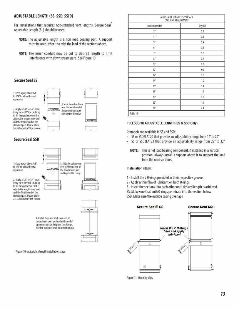
TELESCOPIC ADJUSTABLE LENGTH (SS & SSD Only)
2 models are available in SS and SSD :• SS or SSD0LAT20 that provide an adjustability range from 14”to 20”• SS or SSD0LAT32 that provide an adjustability range from 22” to 32”
NOTE : This is not load bearing component. If installed in a vertical position, always install a support above it to support the load from the next sections.
Installation steps:
1 - Install the 2 0-rings provided in their respective groove;2 - Apply a thin film of lubricant on both 0-rings;3 - Insert the sections into each other until desired length is achieved.SS: Make sure that both 0-rings penetrate into the section belowSSD: Make sure the outside casing overlaps
ADJUSTABLE LENGTH SS/SSD/SSID CAULKING REQUIREMENT
Inside diameter Qty(oz)
3” 0.2
4” 0.3
5” 0.4
6” 0.5
7” 0.6
8” 0.7
9” 0.8
10” 0.9
12” 1.0
14” 1.2
16” 1.4
18” 1.5
20” 1.7
22” 1.9
24” 2.1
Table 13
Figure 11- Opening clips
ADJUSTABLE LENGTH (SS, SSD, SSID)
For installations that requires non-standard vent lengths, Secure Seal® Adjustable Length (AL) should be used.
NOTE: The adjustable length is a non load bearing part. A support must be used after it to take the load of the sections above.
NOTE: The inner conduit may be cut to desired length to limit interference with downstream part. See Figure 10
Figure 10 -Adjustable length installation steps
1. Keep a play about 1/8”to 1/4” to allow thermalexpansion
2. Apply a 1/8” to 1/4” bead (may vary) of Viton caulking to fill the gap between the adjustable length inner wall and the female end of the standard part. Please allow 24-36 hours for Viton to cure.
1. Keep a play about 1/8”to 1/4” to allow thermalexpansion
2. Apply a 1/8” to 1/4” bead (may vary) of Viton caulking to fill the gap between the adjustable length inner wall and the female end of the standard part. Please allow 24-36 hours for Viton to cure.
3. Slide the collar downover the female end ofthe downstream partand tighten the collar
3. Slide the collar downover the female end ofthe downstream part and tighten the clamp
4. Install the outer shell over end ofdownstream part and under the end ofupstream part and tighten the clamps.Need to cut outer shell to correct length.
Secure Seal SS
Secure Seal SSD
14
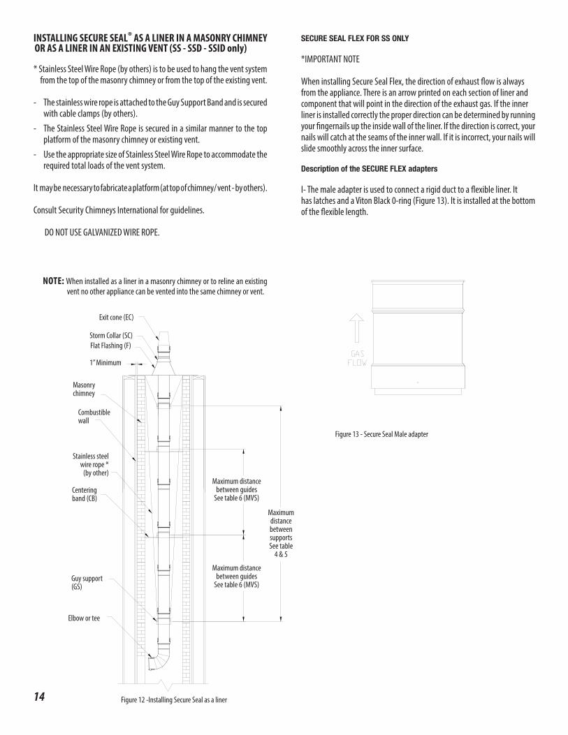
SECURE SEAL FLEX FOR SS ONLY
*IMPORTANT NOTE
When installing Secure Seal Flex, the direction of exhaust flow is alwaysfrom the appliance. There is an arrow printed on each section of liner andcomponent that will point in the direction of the exhaust gas. If the innerliner is installed correctly the proper direction can be determined by running your fingernails up the inside wall of the liner. If the direction is correct, your nails will catch at the seams of the inner wall. If it is incorrect, your nails will slide smoothly across the inner surface.
Description of the SECURE FLEX adapters
I- The male adapter is used to connect a rigid duct to a flexible liner. Ithas latches and a Viton Black 0-ring (Figure 13). It is installed at the bottom of the flexible length.
Figure 13 - Secure Seal Male adapter
NOTE: When installed as a liner in a masonry chimney or to reline an existing vent no other appliance can be vented into the same chimney or vent.
Elbow or tee
Guy support (GS)
Centering band (CB)
Stainless steel wire rope *
(by other)
Combustible wall
Masonry chimney
1” Minimum
Exit cone (EC)
Maximum distance between guides
See table 6 (MVS)
Maximum distance between supports See table
4 & 5
Maximum distance between guides
See table 6 (MVS)
INSTALLING SECURE SEAL® AS A LINER IN A MASONRY CHIMNEY OR AS A LINER IN AN EXISTING VENT (SS - SSD - SSID only)
* Stainless Steel Wire Rope (by others) is to be used to hang the vent system from the top of the masonry chimney or from the top of the existing vent.
- The stainless wire rope is attached to the Guy Support Band and is secured with cable clamps (by others).
- The Stainless Steel Wire Rope is secured in a similar manner to the top platform of the masonry chimney or existing vent.
- Use the appropriate size of Stainless Steel Wire Rope to accommodate the required total loads of the vent system.
It may be necessary to fabricate a platform (at top of chimney/ vent - by others).
Consult Security Chimneys International for guidelines.
DO NOT USE GALVANIZED WIRE ROPE.
Figure 12 -Installing Secure Seal as a liner
Storm Collar (SC)Flat Flashing (F)
15
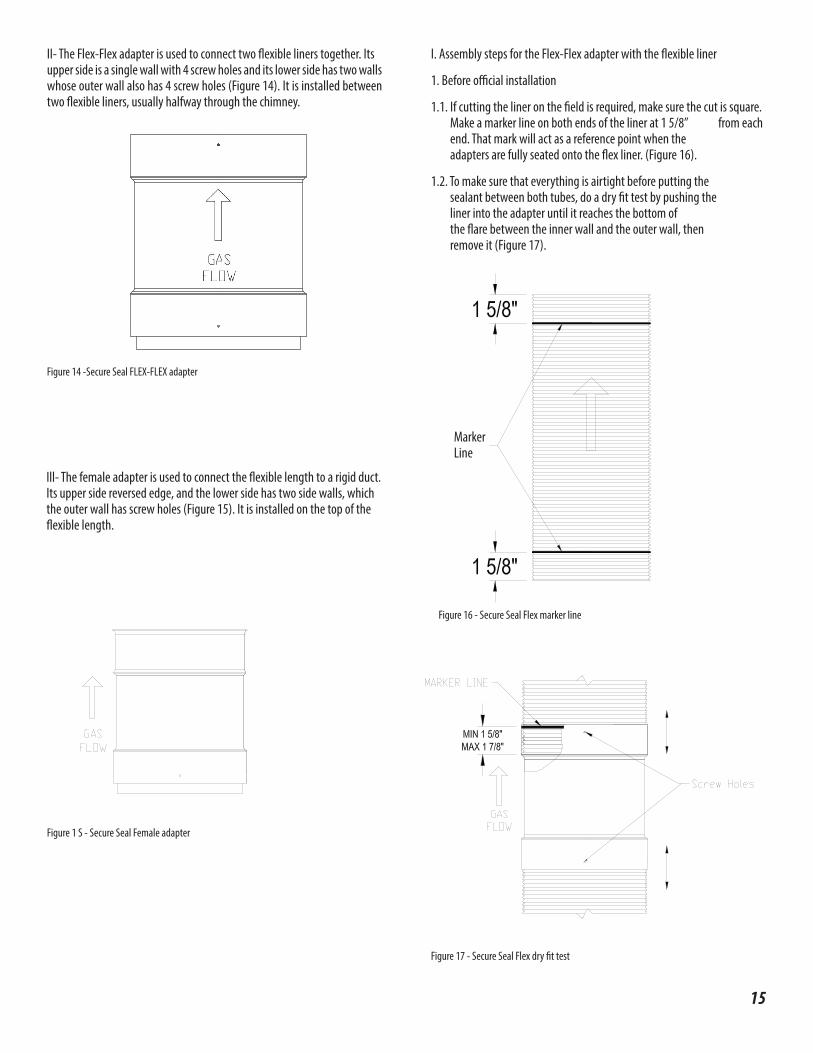
II- The Flex-Flex adapter is used to connect two flexible liners together. Itsupper side is a single wall with 4 screw holes and its lower side has two walls whose outer wall also has 4 screw holes (Figure 14). It is installed between two flexible liners, usually halfway through the chimney.
Ill- The female adapter is used to connect the flexible length to a rigid duct. Its upper side reversed edge, and the lower side has two side walls, which the outer wall has screw holes (Figure 15). It is installed on the top of the flexible length.
I. Assembly steps for the Flex-Flex adapter with the flexible liner
1. Before official installation
1.1. If cutting the liner on the field is required, make sure the cut is square. Make a marker line on both ends of the liner at 1 5/8” from each end. That mark will act as a reference point when the adapters are fully seated onto the flex liner. (Figure 16).
1.2. To make sure that everything is airtight before putting the sealant between both tubes, do a dry fit test by pushing the liner into the adapter until it reaches the bottom of the flare between the inner wall and the outer wall, then remove it (Figure 17).
Figure 14 -Secure Seal FLEX-FLEX adapter
Figure 1 S - Secure Seal Female adapter
Figure 17 - Secure Seal Flex dry fit test
Figure 16 - Secure Seal Flex marker line
Marker Line

16
Official installation of the upper side of the adapter on the flexible liner2.1. Add a bead of Viton® caulking (resistance to condensate) all around
inside the adapter on the beginning of the flare. Add another bead of Viton® caulking all around the outside of the flexible liner at 3/4” from the edge (Figure 18).
Figure 18 -Secure Seal Flex Vi ton• caulking
2.2.Push the adapter on the liner all the way in, until you can’t seethemark made on the flexible liner earlier (Figure 19). Make sure thatthe Viton® caulking is sealed well at the joint inside the adaptorby verifying inside the adaptor.
Figure 19-Secure Seal Flex assembly
2.3. Add a bead of the S-650 red caulking all around the outer junction of the adapter and the flexible liner to make sure everything is well sealed. Also add over the screw holes (Figure 20).
Figure 20- Secure Seal Flex S-650 caulking
Screw holes

17
2.4. lnstall screws in the screw hole and tighten.
2.5. Add the red S-650 caulking over the screws (Figure 21).
Figure 21 -Secure Seal Flex screws
3. Official installation of the lower side of the adapter on the flexible liner
3.1. Add a bead of Viton® caulking (resistance to condensate) all around the adapter between both tubes of the adapter. Just make sure that the gap is well filled about 1 /4” of Viton®.
3.2. Add another bead of Viton® caulking at 1 /2” from the edge of the flexible liner all around the inner side of it (Figure 22).
Figure 22 -Secure Seal Flex Viton® caulking
3.3. Push the adapter on the liner all the way in, until you can’t see the mark made on the flexible liner earlier. Add a bead of the S-650 red caulking all around the outer junction of the adapter and the flexible liner to make sure everything is well sealed. Also add over the screw holes (Figure 23).
Figure 23 -Secure Seal Flex S-650 caulking
3.4. lnstall screws in the screw hole and tighten.
3.5. Add the red S-650 caulking over the screws (Figure 24).
Figure 24 - Secure Seal Flex screws
Stainless Screw No. 6, 1/4” length
18
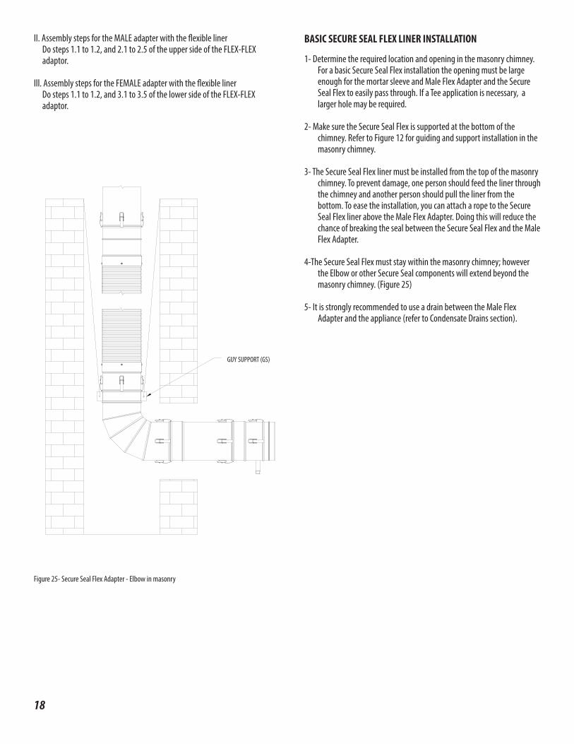
II. Assembly steps for the MALE adapter with the flexible linerDo steps 1.1 to 1.2, and 2.1 to 2.5 of the upper side of the FLEX-FLEXadaptor.
Ill. Assembly steps for the FEMALE adapter with the flexible linerDo steps 1.1 to 1.2, and 3.1 to 3.5 of the lower side of the FLEX-FLEXadaptor.
Figure 25- Secure Seal Flex Adapter - Elbow in masonry
BASIC SECURE SEAL FLEX LINER INSTALLATION
1- Determine the required location and opening in the masonry chimney. For a basic Secure Seal Flex installation the opening must be large enough for the mortar sleeve and Male Flex Adapter and the Secure Seal Flex to easily pass through. If a Tee application is necessary, a larger hole may be required.
2- Make sure the Secure Seal Flex is supported at the bottom of the chimney. Refer to Figure 12 for guiding and support installation in the masonry chimney.
3- The Secure Seal Flex liner must be installed from the top of the masonry chimney. To prevent damage, one person should feed the liner through the chimney and another person should pull the liner from the bottom. To ease the installation, you can attach a rope to the Secure Seal Flex liner above the Male Flex Adapter. Doing this will reduce the chance of breaking the seal between the Secure Seal Flex and the Male Flex Adapter.
4-The Secure Seal Flex must stay within the masonry chimney; however the Elbow or other Secure Seal components will extend beyond the masonry chimney. (Figure 25)
5- It is strongly recommended to use a drain between the Male Flex Adapter and the appliance (refer to Condensate Drains section).
GUY SUPPORT (GS)
19
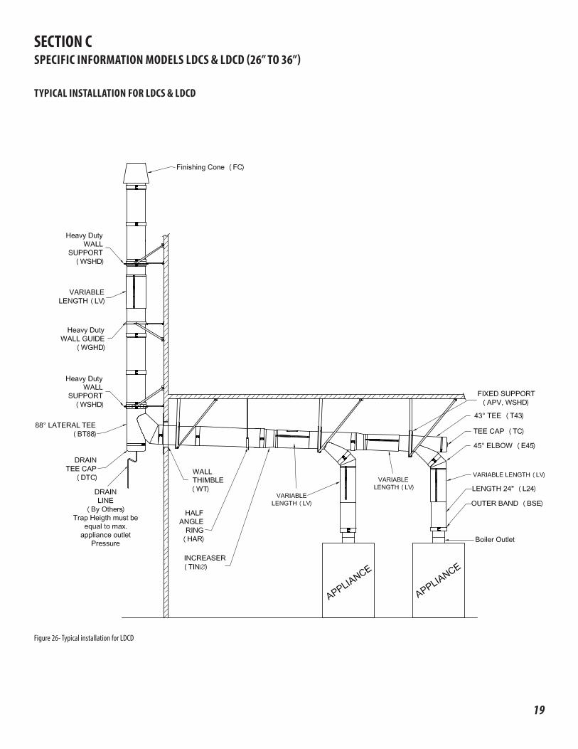
SECTION CSPECIFIC INFORMATION MODELS LDCS & LDCD (26” TO 36”)
TYPICAL INSTALLATION FOR LDCS & LDCD
Figure 26- Typical installation for LDCD

20
7 & 8
7 & 8
6
7 & 8
7 & 8
MAXIMUM HEIGHT SEE TABLE 6
7 & 8
• If Dimension “H” exceeds the value In the Table 7 & 8, use bracingor cable guying to stabilize chimney section above the roof.See Figure 27
Figure 27 - Height with rigid bracing or guying option for LDCS & LDCD Figure 28- Maximum freestanding Height for LDCS & LDCD
TYPICAL INSTALLATION FOR LDCS & LDCD (26” TO 36”)
21
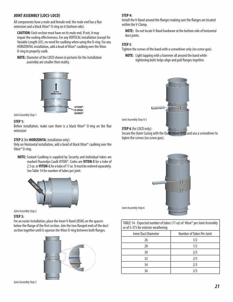
TABLE 14 - Expected number of tubes (11 oz) of Viton® per Joint Assembly or of S-375 for exterior weathering
Inner Duct Diameter Number of Tubes Per Joint26 1/228 1/230 2/332 2/334 2/336 2/3
JOINT ASSEMBLY (LDCS-LDCD)All components have a male and female end: the male end has a flue extension and a black Viton® O-ring on it (bottom side).
CAUTION: Each section must have on its male end. If not, it may impair the sealing effectiveness. For any VERTICAL installation (except for Variable Length (LV), no need for caulking when using the O-ring. For any HORIZONTAL installation, add a bead of Viton® caulking over the Viton O-ring to properly caulk.
NOTE: Diameter of the LDCD shown in pictures for the installation assembly are smaller then reality.
STEP 1:Before installation, make sure there is a black Viton® O-ring on the flue extension STEP 2 (for HORIZONTAL installation only):Only on Horizontal installation, add a bead of black Viton® caulking over the Viton® O-ring.
NOTE: Sealant Caulking is supplied by Security and Individual tubes are marked Fluorodyn Caulk VITON®. Codes are VITON-S for a tube of 2.5 oz. or VITON-L for a tube of 11 oz. It must be ordered separately. See Table 14 for number of tubes per joint.
STEP 3:For an easier installation, place the Inner V-Band (BSIK) on the spacers below the flange of the first section. Join the two flanged ends of the duct section together until it squeeze the Viton O-ring between both flanges.
STEP 4:Install the V-Band around the flanges making sure the flanges are located within the V-Clamp.
NOTE: Do not locate V-Band hardware at the bottom side of horizontal duct joints.
STEP 5:Tighten the screws of the band with a screwdriver only (no screw gun).
NOTE: Light tapping with a hammer all around the band while tightening bolts helps align and pull flanges together.
STEP 6 (for LDCD only):Secure the Outer Casing with the Outer Band (BSE) and use a screwdriver to tigten the screws (no screw gun).
Joint Assembly Step 1
Joint Assembly Step 2
Joint Assembly Step 3
Joint Assembly Step 4-5
Joint Assembly Step 6
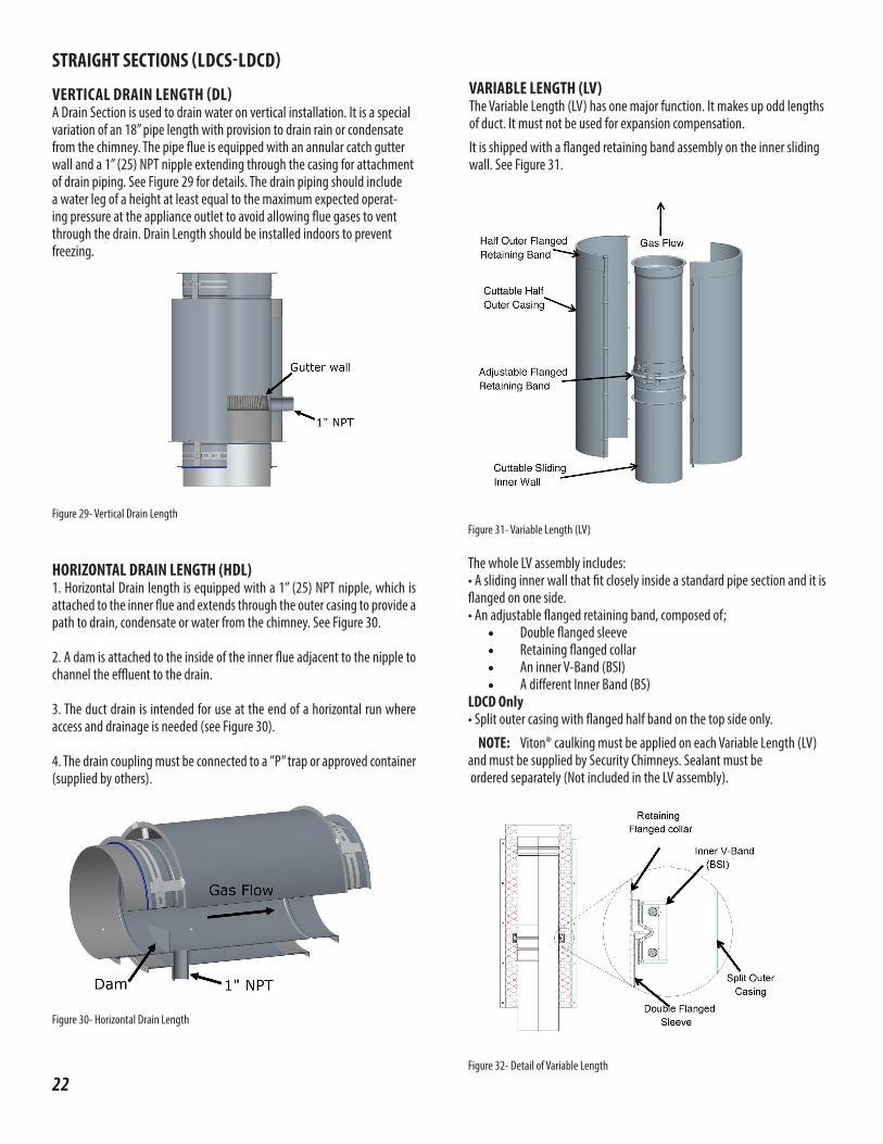
Figure 30- Horizontal Drain Length
22
STRAIGHT SECTIONS (LDCS-LDCD)
VERTICAL DRAIN LENGTH (DL)A Drain Section is used to drain water on vertical installation. It is a special variation of an 18” pipe length with provision to drain rain or condensate from the chimney. The pipe flue is equipped with an annular catch gutter wall and a 1” (25) NPT nipple extending through the casing for attachment of drain piping. See Figure 29 for details. The drain piping should include a water leg of a height at least equal to the maximum expected operat-ing pressure at the appliance outlet to avoid allowing flue gases to vent through the drain. Drain Length should be installed indoors to prevent freezing.
HORIZONTAL DRAIN LENGTH (HDL) 1. Horizontal Drain length is equipped with a 1” (25) NPT nipple, which is attached to the inner flue and extends through the outer casing to provide a path to drain, condensate or water from the chimney. See Figure 30.
2. A dam is attached to the inside of the inner flue adjacent to the nipple to channel the effluent to the drain.
3. The duct drain is intended for use at the end of a horizontal run where access and drainage is needed (see Figure 30).
4. The drain coupling must be connected to a ”P” trap or approved container (supplied by others).
Figure 31- Variable Length (LV)
Figure 32- Detail of Variable Length
VARIABLE LENGTH (LV) The Variable Length (LV) has one major function. It makes up odd lengths of duct. It must not be used for expansion compensation.
It is shipped with a flanged retaining band assembly on the inner sliding wall. See Figure 31.
The whole LV assembly includes:• A sliding inner wall that fit closely inside a standard pipe section and it is flanged on one side.• An adjustable flanged retaining band, composed of;
• Double flanged sleeve• Retaining flanged collar• An inner V-Band (BSI)• A different Inner Band (BS)
LDCD Only• Split outer casing with flanged half band on the top side only.
NOTE: Viton® caulking must be applied on each Variable Length (LV) and must be supplied by Security Chimneys. Sealant must be ordered separately (Not included in the LV assembly).
Figure 29- Vertical Drain Length

Flange to flange length adjustment can range from 7”x 281/2”
NOTE: If the flue is too long to fit into the adjacent section of duct without interfering with the flow path, it should be trimmed to desired flange to flange length plus an overlap of 4” with the inner wall of the inlet end duct section. The minimum overlap for the outer casing is 1” with the inlet end section outer wall. (See Figure 33 & 35a).
NOTE: If an LV joint must be joined to one of these fittings, the unflanged end of the tube should always point downward or towards downward slope.
Figure 33 - Overlap Details for Variable Length
INSTALLATION STEPS FOR THE VARIABLE LENGTH (LV) (LDCS-LDCD)Step 1- Measure the distance X required for the variable length. See Figure 34.
Figure 34-Step 1 for Installation of Variable length
Step 2 - Cut the inner wall at the dimension X found at the first Step plus 4”. See Figure 35a.
Step 3 - Cut the split outer casing on the opposite side of the flanged half at dimension X plus 1’’. See Figure 35b.
Figure 35a -Step 2 -Cut of the Sliding Inner Wall
Figure 35b - Step 3 -Cut of the Outer Casing
Cut Split Outercasing to X + 1”
Cut Sliding InnerWall to X + 4”
Distance ”X”
23
24
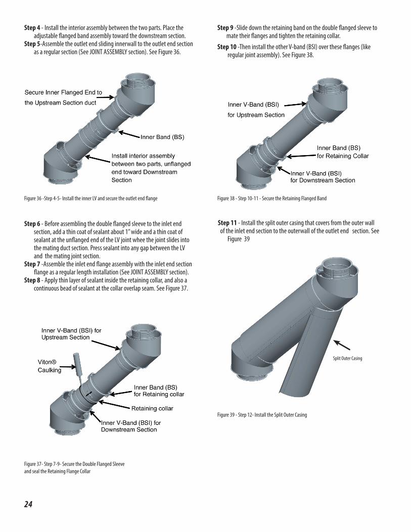
Step 4 - Install the interior assembly between the two parts. Place the adjustable flanged band assembly toward the downstream section.
Step 5-Assemble the outlet end sliding innerwall to the outlet end section as a regular section (See JOINT ASSEMBLY section). See Figure 36.
Step 6 - Before assembling the double flanged sleeve to the inlet end section, add a thin coat of sealant about 1” wide and a thin coat of sealant at the unflanged end of the LV joint whee the joint slides into the mating duct section. Press sealant into any gap between the LV and the mating joint section.
Step 7 -Assemble the inlet end flange assembly with the inlet end section flange as a regular length installation (See JOINT ASSEMBLY section).
Step 8 - Apply thin layer of sealant inside the retaining collar, and also a continuous bead of sealant at the collar overlap seam. See Figure 37.
Figure 36 -Step 4-5- Install the inner LV and secure the outlet end flange
Figure 37- Step 7-9- Secure the Double Flanged Sleeveand seal the Retaining Flange Collar
Step 9 -Slide down the retaining band on the double flanged sleeve to mate their flanges and tighten the retaining collar.
Step 10 -Then install the other V-band (BSI) over these flanges (like regular joint assembly). See Figure 38.
Figure 38 - Step 10-11 - Secure the Retaining Flanged Band
Step 11 - Install the split outer casing that covers from the outer wall of the inlet end section to the outerwall of the outlet end section. See
Figure 39
Figure 39 - Step 12- Install the Split Outer Casing
Split Outer Casing
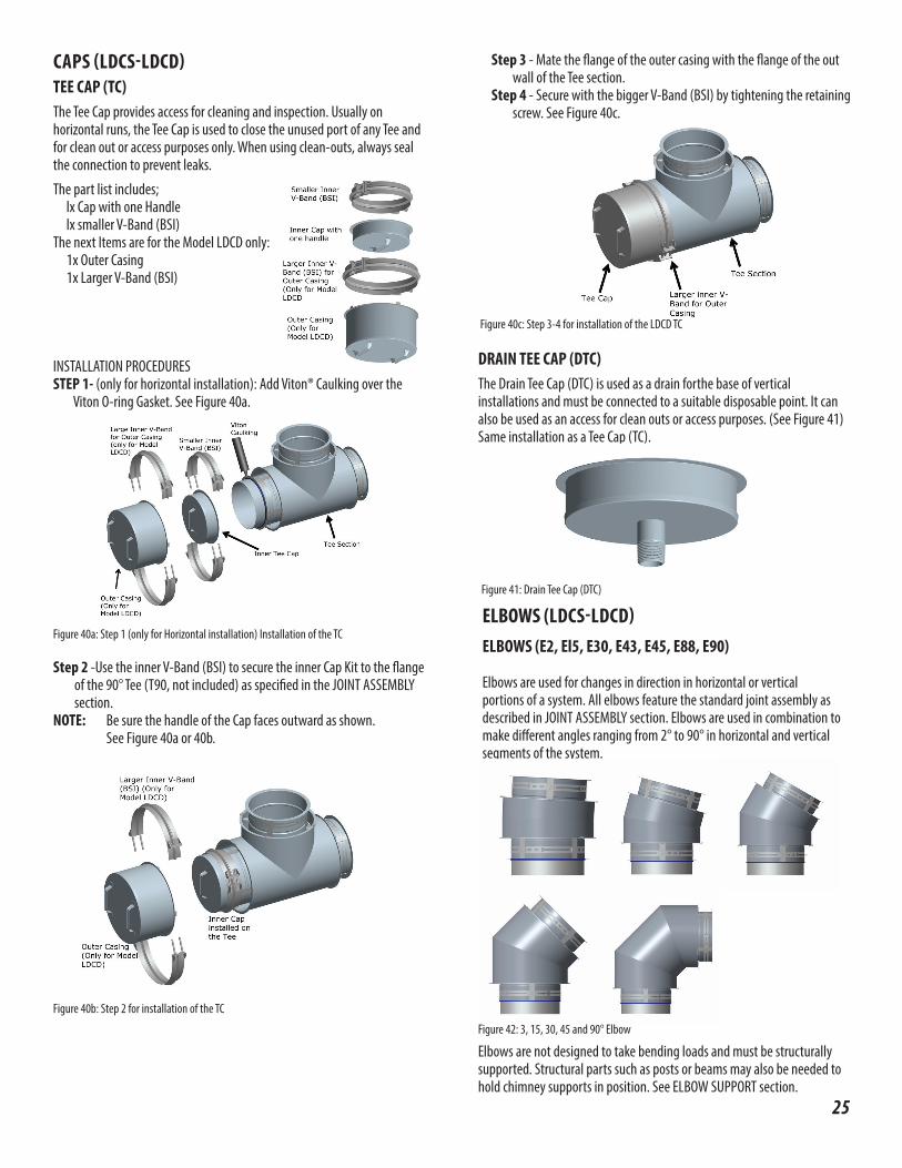
CAPS (LDCS-LDCD)TEE CAP (TC) The Tee Cap provides access for cleaning and inspection. Usually on horizontal runs, the Tee Cap is used to close the unused port of any Tee and for clean out or access purposes only. When using clean-outs, always seal the connection to prevent leaks.
The part list includes;lx Cap with one Handlelx smaller V-Band (BSI)
The next Items are for the Model LDCD only:1x Outer Casing1x Larger V-Band (BSI)
INSTALLATION PROCEDURESSTEP 1- (only for horizontal installation): Add Viton® Caulking over the
Viton O-ring Gasket. See Figure 40a.
Step 2 -Use the inner V-Band (BSI) to secure the inner Cap Kit to the flange of the 90° Tee (T90, not included) as specified in the JOINT ASSEMBLY section.
NOTE: Be sure the handle of the Cap faces outward as shown. See Figure 40a or 40b.
Figure 40b: Step 2 for installation of the TC
DRAIN TEE CAP (DTC) The Drain Tee Cap (DTC) is used as a drain forthe base of vertical installations and must be connected to a suitable disposable point. It can also be used as an access for clean outs or access purposes. (See Figure 41) Same installation as a Tee Cap (TC).
ELBOWS (LDCS-LDCD)ELBOWS (E2, El5, E30, E43, E45, E88, E90)
Elbows are used for changes in direction in horizontal or vertical portions of a system. All elbows feature the standard joint assembly as described in JOINT ASSEMBLY section. Elbows are used in combination to make different angles ranging from 2° to 90° in horizontal and vertical segments of the system.
Elbows are not designed to take bending loads and must be structurally supported. Structural parts such as posts or beams may also be needed to hold chimney supports in position. See ELBOW SUPPORT section.
Figure 42: 3, 15, 30, 45 and 90° Elbow
Figure 40a: Step 1 (only for Horizontal installation) Installation of the TC
Figure 41: Drain Tee Cap (DTC)
Step 3 - Mate the flange of the outer casing with the flange of the out wall of the Tee section.
Step 4 - Secure with the bigger V-Band (BSI) by tightening the retaining screw. See Figure 40c.
Figure 40c: Step 3-4 for installation of the LDCD TC
25

26
OFFSETS (LDCS-LDCD)1. The length of the offset is determined by strength considerations. The
maximum dimension between supports is given in Table 7 & 8, and is applicable to all horizontal and sloped orientations. See Figure 44.
2. The minimum offset is accomplished with two elbows directly connected to each other (see Figure 43 and Table 15 & 16).
3. With frequent re-support, there is no structural or operating limit to the length of horizontal or sloped portions, providing the system meets the capacity, pressure drop of available equipment.
4. The carrying capacity of supports and their structural attachments must take into account the weight of the offset plus whatever vertical section is carried by that support.
5. Height limits for supports are tabulated in Table 6.
6. The vertical sections above the offset must also be supported or anchored and guided where necessary.
7. Anchor Plate Wall Support (WSHD) and Wall Guide (WGHD) may be used in a variety of ways for offset support to achieve the structural stability of the system.
8. Re-supports must be securely anchored to walls, posts, or locally fabricated rigid framework. This framework must be designed to assure stability of supports, such as Ventilated anchor Plate (APV)supports and Heavy Duty Wall Supports (WSHD).
9. Supports suspended by threaded rods or from small size angles or straps are usually not satisfactory to resist bending moments due to offsets.
Figure 44: Maximum Spacing between supports for Offset
ADAPTERS (LDCS-LDCD)TAPERED INCREASER (TIN0)The Tapered Increaser Adapter is used for a diameter change in duct system. Uses when there is a sufficient length for duct run available for the size change. The TIN0 is used uses 2” of length per 1 “increment diameter change. The TIN0 is considered to have the same load strength as a straight duct. See Figure 45.
Figure 45: Tapered Increaser Adapter (TIN0)
ECCENTRIC TAPERED INCREASER (ETIN0)The Eccentric Tapered Increaser Adapter is similar as the Tapered IncreaserAdapter except the smaller diameter is offset from the larger diameter. When installed horizontally, the ETIN0 keep a flat slope unlike the TIN0.See Figure 46.
Figure 46: Eccentric Tapered Increaser (ETIN0)
Figure 43: Minimum Offset for each Elbows
LDCS
Flue Diameter Ø (in.)
3° 15° 30° 45° 90°
26 3/8 2 5/8 6 7/8 12 7/16 34 1/4
28 3/8 2 11/16 7 1/8 13 36 1/4
30 3/8 2 3/4 7 3/8 13 9/16 38 1/4
32 3/8 2 7/8 7 5/8 14 1/8 40 1/4
34 3/8 2 15/16 7 15/16 14 3/4 42 1/4
36 3/8 3 8 3/16 15 5/16 44 1/4
TABLE 15 - Minimum Offset for Each Elbow - LDCS
Dimensions are in inches
LDCD
Flue Diameter Ø (in.)
3° 15° 30° 45° 90°
26 1/2 3 1/4 8 1/8 14 3/8 39 1/2
28 1/2 3 1/4 8 3/8 14 7/8 41 1/2
30 1/2 3 3/8 8 5/8 15 1/2 43 1/2
32 1/2 3 3/8 8 7/8 16 1/8 45 1/2
34 1/2 3 1/2 9 1/8 16 3/4 47 1/2
36 1/2 3 1/2 9 1/2 17 1/4 49 1/2
TABLE 16- Minimum Offset for Each Elbow - LDCD
Dimensions are in inches
Table 7 & 8
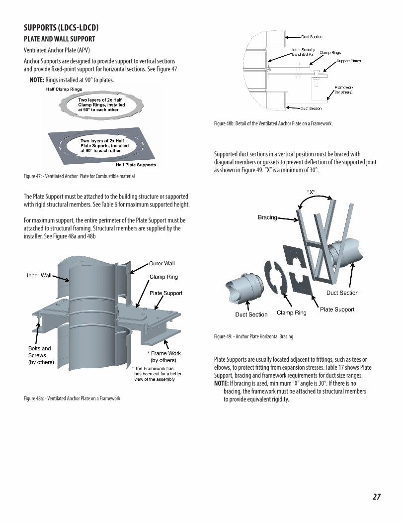
SUPPORTS (LDCS-LDCD)PLATE AND WALL SUPPORTVentilated Anchor Plate (APV)
Anchor Supports are designed to provide support to vertical sectionsand provide fixed-point support for horizontal sections. See Figure 47
NOTE: Rings installed at 90° to plates.
Figure 47: - Ventilated Anchor Plate for Combustible material
The Plate Support must be attached to the building structure or supported with rigid structural members. See Table 6 for maximum supported height.
For maximum support, the entire perimeter of the Plate Support must be attached to structural framing. Structural members are supplied by the installer. See Figure 48a and 48b
Figure 48a: - Ventilated Anchor Plate on a Framework
Figure 48b: Detail of the Ventilated Anchor Plate on a Framework.
Supported duct sections in a vertical position must be braced with diagonal members or gussets to prevent deflection of the supported joint as shown in Figure 49. ”X” is a minimum of 30°.
Plate Supports are usually located adjacent to fittings, such as tees orelbows, to protect fitting from expansion stresses. Table 17 shows Plate Support, bracing and framework requirements for duct size ranges.NOTE: If bracing is used, minimum “X” angle is 30°. If there is no bracing, the framework must be attached to structural members
to provide equivalent rigidity.
Figure 49: - Anchor Plate Horizontal Bracing
27
28
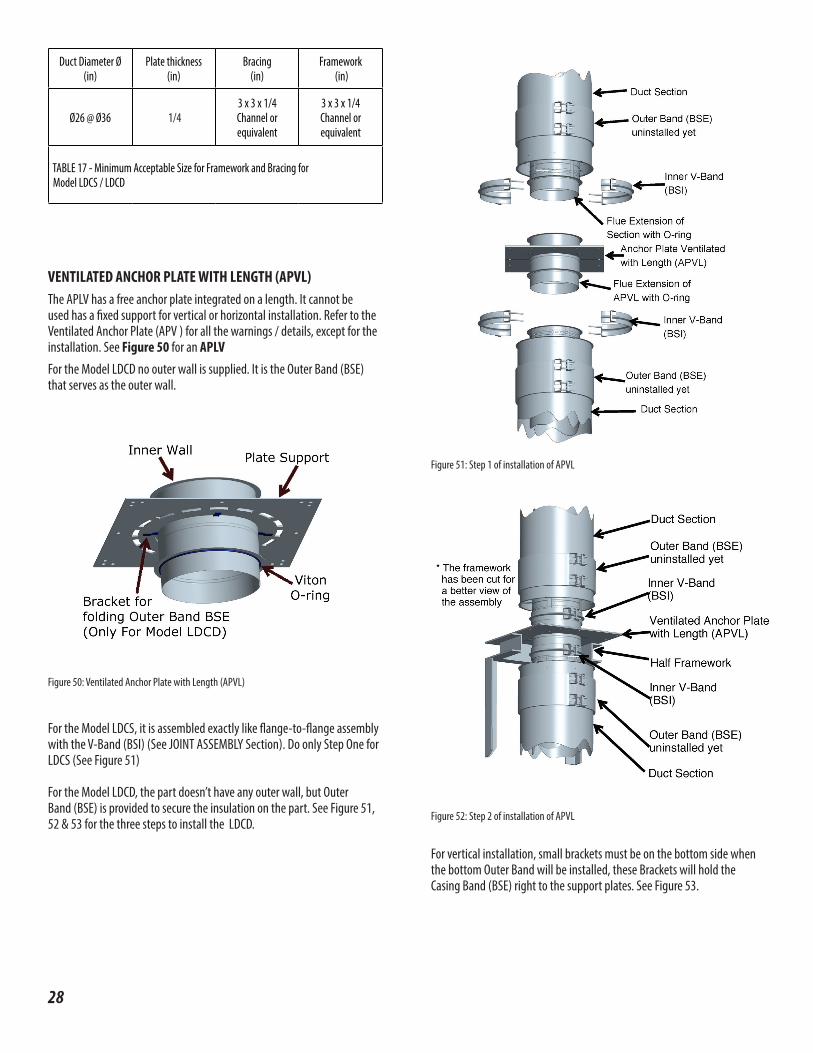
VENTILATED ANCHOR PLATE WITH LENGTH (APVL) The APLV has a free anchor plate integrated on a length. It cannot be used has a fixed support for vertical or horizontal installation. Refer to the Ventilated Anchor Plate (APV ) for all the warnings / details, except for the installation. See Figure 50 for an APLVFor the Model LDCD no outer wall is supplied. It is the Outer Band (BSE) that serves as the outer wall.
For the Model LDCS, it is assembled exactly like flange-to-flange assembly with the V-Band (BSI) (See JOINT ASSEMBLY Section). Do only Step One for LDCS (See Figure 51)
For the Model LDCD, the part doesn’t have any outer wall, but OuterBand (BSE) is provided to secure the insulation on the part. See Figure 51, 52 & 53 for the three steps to install the LDCD.
Figure 50: Ventilated Anchor Plate with Length (APVL)
Figure 51: Step 1 of installation of APVL
Figure 52: Step 2 of installation of APVL
For vertical installation, small brackets must be on the bottom side when the bottom Outer Band will be installed, these Brackets will hold the Casing Band (BSE) right to the support plates. See Figure 53.
Duct Diameter Ø (in)
Plate thickness (in)
Bracing (in)
Framework (in)
Ø26 @ Ø36 1/4 3 x 3 x 1/4 Channel or equivalent
3 x 3 x 1/4 Channel or equivalent
TABLE 17 - Minimum Acceptable Size for Framework and Bracing for Model LDCS / LDCD
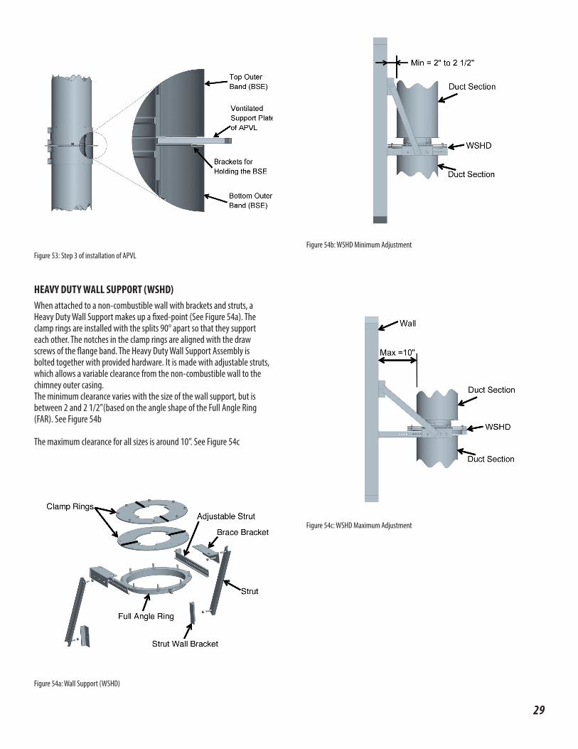
Figure 53: Step 3 of installation of APVL
HEAVY DUTY WALL SUPPORT (WSHD) When attached to a non-combustible wall with brackets and struts, aHeavy Duty Wall Support makes up a fixed-point (See Figure 54a). Theclamp rings are installed with the splits 90° apart so that they supporteach other. The notches in the clamp rings are aligned with the drawscrews of the flange band. The Heavy Duty Wall Support Assembly isbolted together with provided hardware. It is made with adjustable struts, which allows a variable clearance from the non-combustible wall to the chimney outer casing.The minimum clearance varies with the size of the wall support, but isbetween 2 and 2 1/2”(based on the angle shape of the Full Angle Ring(FAR). See Figure 54b
The maximum clearance for all sizes is around 10”. See Figure 54c
Figure 54a: Wall Support (WSHD)
Figure 54c: WSHD Maximum Adjustment
Figure 54b: WSHD Minimum Adjustment
29
30
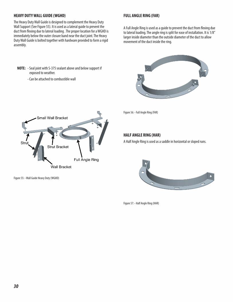
Figure 55: - Wall Guide Heavy Duty (WGHD)
HEAVY DUTY WALL GUIDE (WGHD) The Heavy Duty Wall Guide is designed to complement the Heavy Duty Wall Support (See Figure 55). It is used as a lateral guide to prevent the duct from flexing due to lateral loading . The proper location for a WGHD is immediately below the outer closure band near the duct joint. The Heavy Duty Wall Guide is bolted together with hardware provided to form a rigid assembly.
NOTE: - Seal joint with S-375 sealant above and below support if exposed to weather.
- Can be attached to combustible wall
FULL ANGLE RING (FAR)
A Full Angle Ring is used as a guide to prevent the duct from flexing due to lateral loading. The angle ring is split for ease of installation. It is 1/8” larger inside diameter than the outside diameter of the duct to allow movement of the duct inside the ring.
Figure 56: - Full Angle Ring (FAR)
HALF ANGLE RING (HAR) A Half Angle Ring is used as a saddle in horizontal or sloped runs.
Figure 57: - Half Angle Ring (HAR)

LOCATION OF SUPPORTS (LDCS-LDCD)Supports can be used in different combinations to secure grease duct in place. See Figure 26, 27 and 28 for typical support and guide locations.
VARIABLE LENGTH SUPPORTTo prevent the LV from sagging, it is recommended that the duct section adjacent to a LV is supported or guided. See Figure 58 for typical support locations for Variable Length. When necessary, properly guide the Variable Length (LV) by installing a Heavy Duty Wall Guide (WGHD) or any support immediately on the next (upstream) section.
Figure 58: - Typical Installation locations for the Variable Lengths
NOTE: LV overlapping joints are not intended to support any weight in the vertical position. The inlet and outlet ends must each be supported.
TEE SUPPORTThe Tees must be supported properly to protect them from bending. It can be done by means of Anchor Plate (AP), Anchor Plate with Length (APL) or Heavy Duty Wall Support (WSHD)
When a tee is used at the base of the riser, the preferred location for sup-port is above the Tee, thus suspending the Tee. See Figure 59
A Heavy Duty Wall Support (WSHD), a Ventilated Anchor Plate (APV) or a Ventilated Anchor Plate with Length (APVL) can be used to support the TEE.
Figure 59: - Suspended Tee Support
NOTE: In the case of an AP, Flange joint of duct and Tee are to besecured in place between the Clamp Rings. If it is not possible tosuspend the Tee, it may be supported with a base(a structural steel stand).
When a Tee is used as a supported Tee, A Drain Tee Cap (DTC) must be used at the bottom of the Tee for draining
31

32
ELBOW SUPPORTElbows are to be supported on one end with either a Ventilated Anchor Plate (APV), a Ventilated Anchor Plate with Length (APVL), or a Heavy Duty Wall Support (WSHD). See Figure 60 for an example with an APV and Figure 61 for an example with a (WSHD).
Figure 60: - Elbow with a Ventilated Anchor Plate (APV)
NOTE: In the case of an APV, flange joint of duct and elbow are to be secured in place between the Clamp Ring and square plate support.
Figure 61: - Elbow with an Heavy Duty Wall Support (HOWS)
NOTE: Flange joint of duct and elbow are to be secured in place between the Clamp Rings
ROOF PENETRATION (LDCS-LDCD)STORM COLLAR (SC)The Storm Collar (SC) is used above the flashing for completeweatherization above the roof. It has to be sealed with the outer joint sealant (not included). See Figure 62.
FLASHING (F)The roof Flashing (F) is used in conjunction with Storm Collar (SC) forweatherization on a flat roof. See Figure 63.
ADJUSTABLE FLASHING (F30)The Adjustable Flashing (F30) is used in conjunction with Storm Collar(SC) for weatherization on a roof with a pitch 5° to 30°. See Figure 64.
Figure 62 - Storm Collar
Figure 63 - Flashing
Figure 64 - Adjustable Flashing
NOTE : The flashings are non-ventilated and does not provide for any reduced clearance to combustible.
INSTALLATION PROCEDURE FOR FLASHINGS1. Cut opening to dimensions specified in Table 9, 10 & 11. See Figure 65a
for flat roof and Figure 66 for a sloped roof.NOTE: Reinforced the edges of the hole as appropriate for the expected
lead bearing requirements. 2. Slide chimney section through the hole.
3. For lateral stability, supports or guides must be used. The Heavy Duty Floor Guide (WSHD) must be installed on top of the roof. Any supports (APV, APVL or WSHD) or a Full Angle Ring must be installed below.
NOTE: Flashing is not intended to take any side load or wind loads
4. Install flashing over the grease duct and the guide/support and screw it.
5. The Storm Collar (SC) is placed around the chimney and sealed tothe casing with outer joint sealant S-350. See Figure 66 for an installed Flashing (F)
The storm collar should not quite rest on the flashing when the chimney is cold (a 1/4” gap between the collar and the top of the flashing) .
Duct Section
Half Closure Band(DBSEK)
Heavy Duty WallSupport (WSHD)
Half Closure Band(DBSEK)
45-Degree Elbow(E45)
Wall
Duct Section
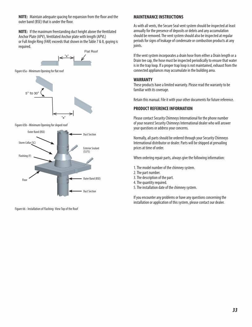
NOTE: Maintain adequate spacing for expansion from the floor and the outer band (BSE) that is under the floor.
NOTE: If the maximum freestanding duct height above the Ventilated Anchor Plate (APV), Ventilated Anchor plate with length (APVL) or Full Angle Ring (FAR) exceeds that shown in the Table 7 & 8, guying is required.
Figure 65a - Minimum Opening for flat roof
Figure 65b - Minimum Opening for sloped roof
Figure 66 - Installation of Flashing- View Top of the Roof
Flat Roof ”x”
5° to 30°
”x”
Outer Band (BSE)
Exterior Sealant (S375)
Duct Section
Flashiing (F)
Storm Collar (SC)
Floor Outer Band (BSE)
Duct Section
33
MAINTENANCE INSTRUCTIONS
As with all vents, the Secure Seal vent system should be inspected at least annually for the presence of deposits or debris and any accumulation should be removed. The vent system should also be inspected at regular periods for signs of leakage of condensate or combustion products at any joints.
If the vent system incorporates a drain hose from either a Drain length or a Drain tee cap, the hose must be inspected periodically to ensure that water is in the trap loop. If a proper trap loop is not maintained, exhaust from the connected appliances may accumulate in the building area.
WARRANTYThese products have a limited warranty. Please read the warranty to befamiliar with its coverage.
Retain this manual. File it with your other documents for future reference.
PRODUCT REFERENCE INFORMATION
Please contact Security Chimneys International for the phone numberof your nearest Security Chimneys International dealer who will answeryour questions or address your concerns.
Normally, all parts should be ordered through your Security ChimneysInternational distributor or dealer. Parts will be shipped at prevailingprices at time of order.
When ordering repair parts, always give the following information:
1. The model number of the chimney system.2. The part number.3. The description of the part.4. The quantity required.5. The installation date of the chimney system.
If you encounter any problems or have any questions concerning the installation or application of this system, please contact our dealer.

Printed in Canada © 2016, 2017 Security Chimneys International PI SECURESEAL LS474 REV. 15 07-14-17
Security Chimneys International Limited reserves the right to make changes at any time, without notice, in design, materials, specifications, prices. Consult your local distributor for chimney system code information.
2125 MONTEREY ST. • LAVAL, QC., CANADA • H7L 3T6800-667-3387; www.securitychimneys.com