Embed Size (px)
Citation preview

462 01 2104 00 Feb. 2012Specifications subject to change without notice.
INSTALLATION INSTRUCTIONSR−410A 2−Stage Single Package Gas/Electric Cooling
PGR524−601 & 3 Phase
NOTE: Read the entire instruction manual before starting theinstallation.NOTE: Installer: Make sure the Owner’s Manual and ServiceInstructions are left with the unit after installation.
TABLE OF CONTENTSPAGE
SAFETY CONSIDERATIONS 1. . . . . . . . . . . . . . . . . . . . . . . . . . . . . . . . .INTRODUCTION 2. . . . . . . . . . . . . . . . . . . . . . . . . . . . . . . . . . . . . . . . . . .RECEIVING AND INSTALLATION 2. . . . . . . . . . . . . . . . . . . . . . . . . . . . .CHECK EQUIPMENT 2. . . . . . . . . . . . . . . . . . . . . . . . . . . . . . . . . . . . . . .PROVIDE UNIT SUPPORT 2. . . . . . . . . . . . . . . . . . . . . . . . . . . . . . . . . .FIELD FABRICATE DUCTWORK 3. . . . . . . . . . . . . . . . . . . . . . . . . . . . .PROVIDE CLEARANCES 3. . . . . . . . . . . . . . . . . . . . . . . . . . . . . . . . . . . .RIG AND PLACE UNIT 3. . . . . . . . . . . . . . . . . . . . . . . . . . . . . . . . . . . . . .
INSPECTION 3. . . . . . . . . . . . . . . . . . . . . . . . . . . . . . . . . . . . . . . . . . . . . .PHYSICAL DATA 9. . . . . . . . . . . . . . . . . . . . . . . . . . . . . . . . . . . . . . . . . . .MAXIMUM GAS FLOW CAPACITY 11. . . . . . . . . . . . . . . . . . . . . . . . . . . .
CONFIGURING UNITS 12. . . . . . . . . . . . . . . . . . . . . . . . . . . . . . . . . . . . . .INSTALL ELECTRICAL CONNECTIONS 13. . . . . . . . . . . . . . . . . . . . . . .
CONTROL VOLTAGE CONNECTIONS 13. . . . . . . . . . . . . . . . . . . . . . . .STANDARD CONNECTION 14. . . . . . . . . . . . . . . . . . . . . . . . . . . . . . . . . .HEAT ANTICIPATOR SETTING 14. . . . . . . . . . . . . . . . . . . . . . . . . . . . . . .TRANSFORMER PROTECTION 14. . . . . . . . . . . . . . . . . . . . . . . . . . . . . .PRE−START−UP 14. . . . . . . . . . . . . . . . . . . . . . . . . . . . . . . . . . . . . . . . . . .CHECK FOR REFRIGERANT LEAKS 15. . . . . . . . . . . . . . . . . . . . . . . . .HEATING AND MAKE ADJUSTMENTS 15. . . . . . . . . . . . . . . . . . . . . . . .
CHECK HEATING CONTROL 15. . . . . . . . . . . . . . . . . . . . . . . . . . . . . . . .CHECK GAS INPUT 16. . . . . . . . . . . . . . . . . . . . . . . . . . . . . . . . . . . . . . . .
ALTITUDE DERATE MULTIPLIER FOR U.S.A. 16. . . . . . . . . . . . . . . . . .ADJUST GAS INPUT 16. . . . . . . . . . . . . . . . . . . . . . . . . . . . . . . . . . . . . . .CHECK BURNER FLAME 17. . . . . . . . . . . . . . . . . . . . . . . . . . . . . . . . . . . .
HEATING INPUTS 17. . . . . . . . . . . . . . . . . . . . . . . . . . . . . . . . . . . . . . . . . .NORMAL OPERATION 26. . . . . . . . . . . . . . . . . . . . . . . . . . . . . . . . . . . . . .
LED INDICATIONS 26. . . . . . . . . . . . . . . . . . . . . . . . . . . . . . . . . . . . . . . . . .AIRFLOW AND TEMPERATURE RISE 26. . . . . . . . . . . . . . . . . . . . . . . .HEATING SEQUENCE OF OPERATION 26. . . . . . . . . . . . . . . . . . . . . . .LIMIT SWITCHES 26. . . . . . . . . . . . . . . . . . . . . . . . . . . . . . . . . . . . . . . . . .ROLLOUT SWITCH 26. . . . . . . . . . . . . . . . . . . . . . . . . . . . . . . . . . . . . . . . .START−UP COOLING AND MAKE ADJUSTMENTS 26. . . . . . . . . . . . .
CHECKING COOLING CONTROL OPERATION 26. . . . . . . . . . . . . . . . .CHECKING AND ADJUSTING REFRIGERANT CHARGE 26. . . . . . . .INDOOR AIRFLOW AND AIRFLOW ADJUSTMENTS 27. . . . . . . . . . . .
OPERATION MODES AND FAN SPEEDS 27. . . . . . . . . . . . . . . . . . . . . .COLOR CODING FOR INDOOR FAN MOTOR LEADS 27. . . . . . . . . . . .
COOLING SEQUENCE OF OPERATION 28. . . . . . . . . . . . . . . . . . . . . . .SUBCOOLING CHARGING CHART 29. . . . . . . . . . . . . . . . . . . . . . . . . . . .DRY COIL AIR DELIVERY 30. . . . . . . . . . . . . . . . . . . . . . . . . . . . . . . . . . . .WET COIL PRESSURE DROP 48. . . . . . . . . . . . . . . . . . . . . . . . . . . . . . . .ECONOMIZER WITH 1−IN. FILTER 48. . . . . . . . . . . . . . . . . . . . . . . . . . . .FILTER PRESSURE DROP TABLE (IN. W.C.) 48. . . . . . . . . . . . . . . . . . .
MAINTENANCE 49. . . . . . . . . . . . . . . . . . . . . . . . . . . . . . . . . . . . . . . . . . . .AIR FILTER 49. . . . . . . . . . . . . . . . . . . . . . . . . . . . . . . . . . . . . . . . . . . . . . . .INDOOR BLOWER AND MOTOR 49. . . . . . . . . . . . . . . . . . . . . . . . . . . . .INDUCED DRAFT BLOWER ASSEMBLY 50. . . . . . . . . . . . . . . . . . . . . .LIMIT SWITCH 50. . . . . . . . . . . . . . . . . . . . . . . . . . . . . . . . . . . . . . . . . . . . .BURNER IGNITION 50. . . . . . . . . . . . . . . . . . . . . . . . . . . . . . . . . . . . . . . . .ELECTRICAL CONTROLS AND WIRING 51. . . . . . . . . . . . . . . . . . . . . . .REFRIGERANT CIRCUIT 52. . . . . . . . . . . . . . . . . . . . . . . . . . . . . . . . . . .PRESSURE SWITCHES 52. . . . . . . . . . . . . . . . . . . . . . . . . . . . . . . . . . . . .REFRIGERANT SYSTEM 53. . . . . . . . . . . . . . . . . . . . . . . . . . . . . . . . . . . .R−410A REFRIGERANT CHARGING 53. . . . . . . . . . . . . . . . . . . . . . . . . .
TROUBLESHOOTING 53. . . . . . . . . . . . . . . . . . . . . . . . . . . . . . . . . . . . . . .START−UP CHECKLIST 53. . . . . . . . . . . . . . . . . . . . . . . . . . . . . . . . . . . .
TROUBLESHOOTING CHART 55. . . . . . . . . . . . . . . . . . . . . . . . . . . . . . . .START−UP CHECKLIST 57. . . . . . . . . . . . . . . . . . . . . . . . . . . . . . . . . . . . .
A09034
Figure 1 − Unit PGR5(Low NOx Model Available)
SAFETY CONSIDERATIONSImproper installation, adjustment, alteration, servicemaintenance, or use can cause explosion, fire, electrical shock,or other conditions which may cause death, personal injury, orproperty damage. Consult a qualified installer, service agency,or your distributor or branch for information or assistance. Thequalified installer or agency must use factory−authorized kits oraccessories when modifying this product. Refer to theindividual instructions packaged with the kits or accessorieswhen installing.Follow all safety codes. Wear safety glasses, protectiveclothing, and work gloves. Have a fire extinguisher available.Read these instructions thoroughly and follow all warnings orcautions included in literature and attached to the unit. consultlocal building codes, the current editions of the National FuelGas Code (NFGC) NFPA 54/ANSI Z223.1, and the NationalElectrical Code (NEC) NFPA 70.In Canada refer to the current editions of the NationalStandards of Canada CAN/CSA−B149.1 and .2 Natural Gasand Propane Installation codes, and Canadian Electrical CodeCSA C22.1Recognize safety information. This is the safety−alert symbol
. When you see this symbol on the unit and in instructions ormanuals, be alert to the potential for personal injury.Understand these signal words: DANGER, WARNING, andCAUTION. These words are used with the safety−alert symbol.DANGER identifies the most serious hazards which will resultin severe personal injury or death. WARNING signifies hazardswhich could result in personal injury or death. CAUTION isused to identify unsafe practices which may result in minorpersonal injury or product and property damage. NOTE is usedto highlight suggestions which will result in enhancedinstallation, reliability, or operation.

2 462 01 2104 00Specifications subject to change without notice.
! WARNINGEXPLOSION HAZARD
Failure to follow this warning couldresult in death serious personalinjury, and/or property damage.
Never use air or gases containingoxygen for leak testing oroperating refrigerant compressors.Pressurized mixtures of air orgases containing oxygen can leadto an explosion.
ELECTRICAL SHOCK HAZARD
Failure to follow this warning could result in personalinjury or death.
Before installing or servicing system, always turn offmain power to system and install lockout tag. Theremay be more than one disconnect switch. Turn offaccessory heater power switch if applicable.
! WARNING
PERSONAL INJURY AND ENVIRONMENTALHAZARD
Failure to relieve system pressure could result inpersonal injury and/or death.
1. Relieve pressure and recover all refrigerant beforeservicing existing equipment, and before final unitdisposal. Use all service ports and open allflow−control devices, including solenoid valves.2. Federal regulations require that you do not ventrefrigerant into the atmosphere. Recover duringsystem repair or final unit disposal.
! WARNING
FIRE, EXPLOSION, ELECTRICAL SHOCK ANDCARBON MONOXIDE POISONING HAZARD
Failure to follow this warning could result in personalinjury or unit damage.
A qualified installer or agency must use onlyfactory−authorized kits or accessories whenmodifying this product.
WARNING!
CUT HAZARD
Failure to follow this caution may result in personalinjury.
When removing access panels (see Figure 16) orperforming maintenance functions inside your unit, beaware of sharp sheet metal parts and screws.Although special care is taken to reduce sharp edgesto a minimum, be extremely careful and wearappropriate protective clothing, safety glasses andgloves when handling parts or reaching into the unit.
! CAUTION
INTRODUCTIONThe PGR5 unit (see Figure 1) is a fully self−contained,combination Category I gas heating/electric cooling unitdesigned for outdoor installation (See Figure 3 and Figure 4
for unit dimensions). All unit sizes have return and dischargeopenings for both horizontal and downflow configurations, andare factory shipped with all downflow duct openings covered.Units may be installed either on a rooftop or on a cement slab.(See Figure 5 for roof curb dimensions).In gas heating mode, this unit is designed for a minimumcontinuous return−air temperature of 55�F (13�C) db and amaximum continuous return−air temperature of 80�F (27�C)db. Failure to follow these return−air temperature limits mayaffect reliability of heat exchangers, motors, and othercomponents.Models with a “1” in the thirteenth position of the model numberare dedicated Low NOx units designed for Californiainstallations. These models meet the California maximumoxides of nitrogen (NOx) emissions requirements of 40nanograms/joule or less as shipped from the factory and mustbe installed in California Air Quality Management Districts orany other regions in North America where a Low NOx ruleexists.NOTE: Low NOx requirements apply only to natural gasinstallations.
RECEIVING AND INSTALLATIONStep 1 — Check EquipmentIdentify UnitThe unit model number and serial number are stamped on theunit information plate. Check this information against shippingpapers.Inspect ShipmentInspect for shipping damage before removing packagingmaterials. If unit appears to be damaged or is torn loose fromits anchorage, have it examined by transportation inspectorsbefore removal. Forward claim papers directly to transportationcompany. Manufacturer is not responsible for any damageincurred in transit. Check all items against shipping list.Immediately notify the nearest equipment distribution office ifany item is missing. To prevent loss or damage, leave all partsin original packages until installation.If the unit is to be mounted on a curb in a downflow application,review Step 9 to determine which method is to be used toremove the downflow panels before rigging and lifting intoplace. The panel removal process may require the unit to be onthe ground.Step 2 — Provide Unit SupportFor hurricane tie downs, contact distributor for details and PE(Professional Engineering) Certificate if required.Roof CurbInstall accessory roof curb in accordance with instructionsshipped with curb (See Figure 5). Install insulation, cant strips,roofing, and flashing. Ductwork must be attached to curb.IMPORTANT: The gasketing of the unit to the roof curbis critical for a water tight seal. Install gasketing materialsupplied with the roof curb. Improperly applied gasketingalso can result in air leaks and poor unit performance.Curb should be level to within 1/4 in. (6 mm). This is necessaryfor unit drain to function properly. Refer to accessory roof curbinstallation instructions for additional information as required.Installation on older “G” series roof curbs.Two accessory kits are available to aid in installing a new “G”series unit on an old “G” roof curb.
1. Accessory kit number CPADCURB001A00, (smallchassis) and accessory kit number CPADCURB002A00,(large chassis) includes roof curb adapter and gasketsfor the perimeter seal and duct openings. No additionalmodifications to the curb are required when using this kit.
2. An alternative to the adapter curb is to modify theexisting curb by removing the outer horizontal flange and

462 01 2104 00 3Specifications subject to change without notice.
use accessory kit number CPGSKTKIT001A00 whichincludes spacer blocks (for easy alignment to existingcurb) and gaskets for the perimeter seal and ductopenings. This kit is used when existing curb is modifiedby removing outer horizontal flange.
UNITS/STRUCTURAL DAMAGE HAZARD
Failure to follow this caution may result in propertydamage.
Ensure there is sufficient clearance for saw bladewhen cutting the outer horizontal flange of the roofcurb so there is no damage to the roof or flashing.
WARNING!
Slab MountPlace the unit on a solid, level pad that is at least 2 in. (51 mm)above grade. The pad should extend approximately 2 in. (51mm) beyond the casing on all 4 sides of the unit. (SeeFigure 2.) Do not secure the unit to the pad except whenrequired by local codes.
OPTIONALRETURN
AIROPENING
OPTIONALSUPPLY
AIROPENING
EVAP. COIL COND. COIL
2˝(50.8mm)
A07926
Figure 2 − Slab Mounting DetailsStep 3 — Field Fabricate DuctworkSecure all ducts to roof curb and building structure on verticaldischarge units. Do not connect ductwork to unit. For horizontalapplications, unit is provided with flanges on the horizontalopenings. All ductwork should be secured to the flanges.Insulate and weatherproof all external ductwork, joints, and roofopenings with counter flashing and mastic in accordance withapplicable codes.Ducts passing through an unconditioned space must beinsulated and covered with a vapor barrier.If a plenum return is used on a vertical unit, the return shouldbe ducted through the roof deck to comply with applicable firecodes.Read unit rating plate for any required clearances aroundductwork. Cabinet return−air static shall not exceed −.25 IN.W.C.Step 4 — Provide ClearancesIMPORTANT: The unit must be secured to the curb byinstalling screws through the bottom of the curb flangeand into the unit base rails. When installing large baseunits onto the common curb, the screws must beinstalled before allowing the full weight of the unit to reston the curb. A minimum of six screws are required forlarge base units. Failure to secure unit properly couldresult in an unstable unit. See Warning nearRigging/Lifting information and accessory curbinstructions for more details.
The required minimum operating and service clearances areshown in Figure 3 and Figure 4. Adequate combustion,ventilation and condenser air must be provided.IMPORTANT: Do not restrict outdoor airflow. An airrestriction at either the outdoor−air inlet or the fandischarge may be detrimental to compressor life.The outdoor fan pulls air through the outdoor coil anddischarges it through the top grille. Be sure that the fandischarge does not recirculate to the outdoor coil. Do notlocate the unit in either a corner or under an overheadobstruction. The minimum clearance under a partial overhang(such as a normal house overhang) is 48−in. (1219 mm) abovethe unit top. The maximum horizontal extension of a partialoverhang must not exceed 48−in. (1219 mm).Do not place the unit where water, ice, or snow from anoverhang or roof will damage or flood the unit. Do not install theunit on carpeting or other combustible materials. Slab−mountedunits should be at least 2 in. (51 mm) above the highestexpected water and runoff levels. Do not use unit if it has beenunder water.
Step 5 — Rig and Place UnitRigging and handling of this equipment can be hazardous formany reasons due to the installation location (roofs, elevatedstructures, etc.).Only trained, qualified crane operators and ground support staffshould handle and install this equipment.When working with this equipment, observe precautions in theliterature, on tags, stickers, and labels attached to theequipment, and any other safety precautions that might apply.Training for operators of the lifting equipment should include,but not be limited to, the following:
1. Application of the lifter to the load, and adjustment of thelifts to adapt to various sizes or kinds of loads.
2. Instruction in any special operation or precaution.3. Condition of the load as it relates to operation of the
lifting kit, such as balance, temperature, etc.Follow all applicable safety codes. Wear safety shoes and workgloves.
InspectionPrior to initial use, and at monthly intervals, all rigging shackles,clevis pins, and straps should be visually inspected for anydamage, evidence of wear, structural deformation, or cracks.Particular attention should be paid to excessive wear at hoisthooking points and load support areas. Materials showing anykind of wear in these areas must not be used and should bediscarded.
UNIT FALLING HAZARD
Failure to follow this warning could result in personalinjury or death.
Never stand beneath rigged units or lift over people.
! WARNING
PROPERTY DAMAGE HAZARD
Failure to follow this warning could result in personalinjury/death or property damage.
When straps are taut, the clevis should be a minimumof 36 in. (914 mm) above the unit top cover.
! WARNING

4 462 01 2104 00Specifications subject to change without notice.
Rigging/Lifting of Unit (See Figure 6)
UNIT FALLING HAZARD
Failure to follow this warning could result in personalinjury or death.
Large base units must be secured to common curbbefore allowing full weight of unit to rest on curb.Install screws through curb into unit base rails whilerigging crane is still supporting unit.
! WARNING
Lifting holes are provided in base rails as shown in Figure 3and Figure 4.
1. Leave top shipping skid on the unit for use as a spreaderbar to prevent the rigging straps from damaging the unit.If the skid is not available, use a spreader bar ofsufficient length to protect the unit from damage.
2. Attach shackles, clevis pins, and straps to the base railsof the unit. Be sure materials are rated to hold the weightof the unit (See Figure 6).
3. Attach a clevis of sufficient strength in the middle of thestraps. Adjust the clevis location to ensure unit is liftedlevel with the ground.
After the unit is placed on the roof curb or mounting pad,remove the top skid.

462 01 2104 00 5Specifications subject to change without notice.
Figure 3 − PGR524−30 Unit Dimensions

6 462 01 2104 00Specifications subject to change without notice.
Figure 4 − PGR536−60 Unit Dimensions

462 01 2104 00 7Specifications subject to change without notice.
RETURN AIR
SMALLBASE UNIT
SUPPLYAIR
LARGEBASE UNIT
UNIT PLACEMENT ON COMMON CURB
LARGE CURB SMALL OR LARGE BASE UNIT
SMALL/COMMON CURB
ROOF CURB DETAIL
Wood nailer*
Roofcurb*
Insulation(field supplied)
*Provided with roofcurb
Cant stripfield supplied
Roofing materialfield supplied
Flashing fieldsupplied
HVAC unitbase rails
Roofcurb
SealingGasket
HVAC unitbasepan
Anchor screw
A09090
A09413
A09094
A09415
C
B
AF
DE
Dashed lines show cross supportlocation for large basepan units.
G
H
C
B
AF
D
E
G
H
A09414
UNITSIZE
CATALOGNUMBER
AIN.
(mm)
B (small / commonbase)
IN. (mm)*
B (largebase)
IN. (mm)*
CIN.
(mm)
DIN.
(mm)
EIN.
(mm)
FIN.
(mm)
GIN. (mm)
HIN. (mm)
Smallor
Large
CPRFCURB010A00 11 (279)10 (254)
14 (356) 16 (406) 47.8(1214)
32.4(822)
2.7 (69)30.6 (778)
46.1 (1170)CPRFCURB011A00 14 (356)
LargeCPRFCURB012A00 11 (279)
14 (356) 43.9(1116) 42.2 (1072)
CPRFCURB013A00 14 (356)
* Part Numbers CPRCURB010A00 and CPRCURB011A00 can be used on both small and large basepan units. The cross supports must be located based on whether theunit is a small basepan or a large basepan.NOTES:
1. Roof curb must be set up for unit being installed.2. Seal strip must be applied, as required, to unit being installed.3. Roof curb is made of 16−gauge steel.4. Attach ductwork to curb (flanges of duct rest on curb).5. Insulated panels: 1−in. (25.4 mm) thick fiberglass 1 lb. density.
Figure 5 − Roof Curb Dimensions

8 462 01 2104 00Specifications subject to change without notice.
ACCESS PANELS MUST BE IN PLACE WHEN RIGGING.PANNEAUX D'ACCES DOIT ÊTRE EN PLACE POUR MANIPULATION.
50CY502286 2.0
CAUTION - NOTICE TO RIGGERSPRUDENCE - AVIS AUX MANIPULATEUR
Use top skid as spreader bar. / Utiliser la palette du haut comme barre de répartition
SEAL STRIP MUST BE INPLACE BEFORE PLACINGUNIT ON ROOF CURB
DUCTS
DETAIL AVOIR DÉTAIL A
MINIMUM HEIGHT: 36" (914.4 mm)HAUTEUR MINIMUM
UNIT HEIGHTHAUTEUR D'UNITÉ
SEE DETAIL AVOIR DÉTAIL A
BANDE SCELLANT DOIT ÊTRE EN PLACE AVANT DE PLACER L'UNITÉ SUR LA BASE DE TOIT
A09051
Standard Copper Tube Aluminum FinSMALL CABINET LARGE CABINET
Unit24 30
Unit *36 42 48 60
lb kg lb kg lb kg lb kg lb kg lb kg
Rigging Weight 352 160 359 163 Rigging Weight 455 206 455 206 500 227 520 236
NOTE: See dimensional drawing for corner weights.
Optional Copper Tube Copper FinSMALL CABINET LARGE CABINET
Unit24 30
Unit *36 42 48 60
lb kg lb kg lb kg lb kg lb kg lb kg
Rigging Weight 390 177 416 189 Rigging Weight 517 235 517 235 584 265 610 277
NOTE: See dimensional drawing for corner weights.Figure 6 − PGR5 Unit Suggested Rigging

462 01 2104 00 9Specifications subject to change without notice.
Table 1 – Physical Data − Unit PGR5
UNIT SIZE 24040 24060 30040 30060 36060 36090 42060 42090
NOMINAL CAPACITY (ton) 2 2 2−1/2 2−1/2 3 3 3−1/2 3−1/2
SHIPPING WEIGHT** lb.SHIPPING WEIGHT** (kg)
352160
352160
359163
359163
455206
455206
455206
455206
COMPRESSORS Quantity
Scroll
1
REFRIGERANT (R−410A) Quantity lb. Quantity (kg)
6.42.9
6.42.9
8.33.8
8.33.8
8.13.7
8.13.7
8.73.9
8.73.9
REFRIGERANT METERING DEVICE TXV
OUTDOOR COIL Rows...Fins/in. Face Area (sq ft)
1..2113.6
1...2113.6
2...2113.6
2...2113.6
2...2113.6
2...2113.6
2...2113.6
2...21 13.6
OUTDOOR FAN Nominal CFM Diameter in. Diameter (mm) Motor Hp (Rpm)
250024
609.61/10 (810)
250024
609.61/10 (810)
270024
609.61/5 (810)
270024
609.61/5 (810)
300026
600.41/5 (810)
300026
600.41/5 (810)
300026
660.41/5 (810
300026
660.41/5 (810)
INDOOR COIL Rows...Fins/in. Face Area (sq ft)
3...173.7
3...173.7
3...173.7
3...173.7
3...174.7
3...174.7
3...174.7
3...174.7
INDOOR BLOWER Nominal Low Stage Cooling Airflow (Cfm) Nominal High Stage Cooling Airflow (Cfm) Size in. Size (mm.) Motor HP (RPM)
600 600 750 750 900 900 1050 1050600800
10x10254x254
1/2 (1050)
600800
10x10254x254
1/2 (1050)
750100010x10
254x2541/2 (1050)
750100010x10
254x2541/2 (1050)
900120011x10
279.4x2543/4 (1000)
900120011x10
279.4x2543/4 (1000)
1050140011x10
279.4x2543/4 (1075)
1050140011x10
279.4x2543/4 (1075)
FURNACE SECTION*
Burner Orifice No. (Qty...Drill Size) Natural Gas (Factory Installed) Propane Gas
2...442...55
3...443...55
2...442...55
3...443...55
VAC Models3...443...55
3…383…53
VAC Models3...443...55
3...383...53
HIGH−PRESSURE SWITCH(psig) Cut−out Reset (Auto)
650 +/− 15420 +/− 25
LOSS−OF−CHARGE / LOW−PRESSURESWITCH (Liquid Line) (psig) cut−out Re-set (auto)
50 +/− 795 +/− 7
RETURN−AIR FILTERS†�Throwaway Size in.
(mm)20x20x1
508x508x2520x24x1
508x610x2524x30x1
610x762x25
*Based on altitude of 0 to 2000 ft (0−610 m).� Required filter sizes shown are based on the larger of the AHRI (Air Conditioning Heating and Refrigeration Institute) rated cooling airflow or the heating airflow velocityof 300 ft/minute for throwaway type. Air filter pressure drop for non−standard filters must not exceed 0.08 IN. W.C.� If using accessory filter rack refer to the filter rack installation instructions for correct filter sizes and quantity.
10 462 01 2104 00Specifications subject to change without notice.
Table 1—Physical Data Con’t − Unit PGR5UNIT SIZE 48090 48115 48130 60090 60115 60130
NOMINAL CAPACITY (ton) 4 4 4 5 5 5
SHIPPING WEIGHT lbSHIPPING WEIGHT kg
500227
500227
500227
520236
520236
520236
COMPRESSORS Quantity
Scroll
1
REFRIGERANT (R-410A) Quantity lb Quantity (kg.)
10.84.9
10.84.9
10.84.9
12.15.5
12.15.5
12.15.5
REFRIGERANT METERING DEVICE TXV
OUTDOOR COIL Rows...Fins/in. Face Area (sq ft)
2...2119.4
2...2119.4
2...2119.4
2...2121.4
2...2121.4
2...2121.4
OUTDOOR FAN Nominal Cfm Diameter in. Diameter (mm) Motor Hp (Rpm)
330026
660.41/5 (810)
330026
660.41/5 (810)
330026
660.41/5 (810)
360026
660.41/5 (810)
360026
660.41/5 (810)
360026
660.41/5 (810)
INDOOR COIL Rows...Fins/in. Face Area (sq ft)
3...175.7
3...175.7
3...175.7
3...175.7
3...175.7
3...175.7
INDOOR BLOWER Nominal Low Stage Cooling Airflow (Cfm) Nominal High Stage Cooling Airflow (Cfm) Size in. Size (mm) Motor HP (RPM)
1200 1200 1200 1200 1200 12001200160011x10
279.4x2541.0 (1075)
1200160011x10
279.4x2541.0 (1075)
1200160011x10
279.4x2541.0 (1075)
1200175011x10
279.4x2541.0 (1075)
1200175011x10
279.4x2541.0 (1075)
1200175011x10
279.4x2541.0 (1075)
FURNACE SECTION*Burner Orifice No. (Qty...Drill Size) Natural Gas (Factory Installed) Propane Gas
3...383...53
3...333...51
3...313...49
3...383...53
3...333...51
3...313...49
HIGH−PRESSURE SWITCH(psig) Cut−out Reset (Auto)
650 +/− 15420 +/− 25
LOSS−OF−CHARGE / LOW−PRESSURESWITCH (psig) cut−out Reset (auto)
50 +/−795 +/− 7
RETURN−AIR FILTERS Throwaway†� in. (mm)
24x36x1 610x914x25
*Based on altitude of 0 to 2000 ft (0−610 m).� Required filter sizes shown are based on the larger of the AHRI (Air Conditioning Heating and Refrigeration Institute) rated cooling airflow or the heating airflow velocityof 300 ft/minute for throwaway type. Air filter pressure drop for non−standard filters must not exceed 0.08 IN. W.C.� If using accessory filter rack refer to the filter rack installation instructions for correct filter sizes and quantity.
Step 6 — Connect Condensate DrainNOTE: When installing condensate drain connection be sureto comply with local codes and restrictions.Model PGR5 disposes of condensate water through a 3/4 in.NPT fitting which exits through the base on the evaporator coilaccess side. See Figure 3 & Figure 4 for location.Condensate water can be drained directly onto the roof inrooftop installations (where permitted) or onto a gravel apron inground level installations. Install a field−supplied 2−in. (51 mm)condensate trap at the end of condensate connection to ensureproper drainage. Make sure that the outlet of the trap is at least1 in. (25 mm) lower than the drain−pan condensate connectionto prevent the pan from overflowing (See Figure 7). Prime thetrap with water. When using a gravel apron, make sure it slopesaway from the unit.
TRAPOUTLET
1-in. (25 mm) min.
2-in. (51 mm) min.
A09052
Figure 7 − Condensate TrapConnect a drain tube using a minimum of 3/4−in. PVC or3/4−in. copper pipe (all field−supplied) at the outlet end of the2−in. (51 mm) trap. Do not undersize the tube. Pitch the drain
tube downward at a slope of at least 1−in. (25 mm) for every 10ft (3.1 m) of horizontal run. Be sure to check the drain tube forleaks.
Step 7 — Install Flue HoodThe flue assembly is secured and shipped in the return air duct.Remove duct cover to locate the assembly (See Figure 9).NOTE: Dedicated low NOx models MUST be installed inCalifornia Air Quality Management Districts where a Low NOxrule exists.
These models meet the California maximum oxides of nitrogen(NOx) emissions requirements of 40 nanograms/joule or lessas shipped from the factory.NOTE: Low NOx requirements apply only to natural gasinstallations.
CARBON MONOXIDE POISONING HAZARD
Failure to follow this warning could result in personalinjury or death.
The venting system is designed to ensure properventing. The flue hood assembly must be installed asindicted in this section of the unit installationinstructions.
! WARNING
Install the flue hood as follows:1. This installation must conform with local building codes
and with NFPA 54/ANSI Z223.1 National Fuel Gas Code(NFGC), (in Canada, CAN/CGA B149.1, and B149.2)latest revision. Refer to Provincial and local plumbing orwastewater codes and other applicable local codes.

462 01 2104 00 11Specifications subject to change without notice.
2. Remove flue hood from shipping location (inside thereturn section of the blower compartment−see Figure 9).Remove the return duct cover to locate the flue hood.Place flue hood assembly over flue panel. Orient screwholes in flue hood with holes in the flue panel.
3. Secure flue hood to flue panel by inserting a single screwon the top flange and the bottom flange of the hood.
Step 8 — Install Gas PipingThe gas supply pipe enters the unit through the access holeprovided. The gas connection to the unit is made to the 1/2−in.(12.7 mm) FPT gas inlet on the gas valve.Install a gas supply line that runs to the heating section. Referto the NFGC for gas pipe sizing. Do not use cast−iron pipe. It isrecommended that a black iron pipe is used. Check the localutility for recommendations concerning existing lines. Size gassupply piping for 0.5 IN. W.C. maximum pressure drop. Neveruse pipe smaller than the 1/2−in. (12.7 mm) FPT gas inlet onthe unit gas valve.For natural gas applications, the gas pressure at unit gasconnection must not be less than 4.0 IN. W.C. or greater than13 IN. W.C. while the unit is operating. For propaneapplications, the gas pressure must not be less than 11.0 IN.W.C. or greater than 13 IN. W.C. at the unit connection.A 1/8−in. (3.2 mm) NPT plugged tapping, accessible for testgauge connection, must be installed immediately upstream ofthe gas supply connection to the gas valve.When installing the gas supply line, observe local codespertaining to gas pipe installations. Refer to the NFPA 54/ANSIZ223.1 latest edition (in Canada, CAN/CGA B149.1).NOTE: In the state of Massachusetts:
1. Gas supply connections MUST be performed by alicensed plumber or gas fitter.
2. When flexible connectors are used, the maximum lengthshall not exceed 36 inches (915 mm).
3. When lever handle type manual equipment shutoffvalves are used, they shall be T−handle valves.
4. The use of copper tubing for gas piping is NOT approvedby the state of Massachusetts.
In the absence of local building codes, adhere to the followingpertinent recommendations:
1. Avoid low spots in long runs of pipe. Grade all pipe 1/4in. (6.35 mm) for every 15 ft (4.6 m) of length to preventtraps. Grade all horizontal runs downward to risers. Userisers to connect to heating section and to meter.
2. Protect all segments of piping system against physicaland thermal damage. Support all piping with appropriate
straps, hangers, etc. Use a minimum of one hangerevery 6 ft (1.8 m). For pipe sizes larger than 1/2 in.,follow recommendations of national codes.
3. Apply joint compound (pipe dope) sparingly and only tomale threads of joint when making pipe connections. Useonly pipe dope that is resistant to action of liquefiedpetroleum gases as specified by local and/or nationalcodes. Never use Teflon tape.
4. Install sediment trap in riser leading to heating section(See Figure 8). This drip leg functions as a trap for dirtand condensate.
5. Install an accessible, external, manual main shutoff valvein gas supply pipe within 6 ft (1.8 m) of heating section.
6. Install ground−joint union close to heating sectionbetween unit manual shutoff and external manual mainshut−off valve.
7. Pressure test all gas piping in accordance with local andnational plumbing and gas codes before connectingpiping to unit.
OUTTEE
NIPPLE
CAP
IN
C99020
Figure 8 − Sediment TrapNOTE: Pressure test the gas supply system after the gassupply piping is connected to the gas valve. The supply pipingmust be disconnected from the gas valve during the testing ofthe piping systems when test pressure is in excess of 0.5 psig.Pressure test the gas supply piping system at pressures equalto or less than 0.5 psig. The unit heating section must beisolated from the gas piping system by closing the externalmain manual shutoff valve and slightly opening theground−joint union.
Table 2 – Maximum Gas Flow Capacity*
NOMINALIRON PIPESIZE (IN.)
INTERNALDIAMETER
(IN.)
LENGTH OF PIPE FT (m)†
10(3)
20(6)
30(9)
40(12)
50(15)
60(18)
70(21)
80(24)
90(27)
100(30)
125(38)
150(46)
175(53)
200(61)
1/2 .622 175 120 97 82 73 66 61 57 53 50 44 40 — —
3/4 .824 360 250 200 170 151 138 125 118 110 103 93 84 77 72
1 1.049 680 465 375 320 285 260 240 220 205 195 175 160 145 135
1-1/4 1.380 1400 950 770 600 580 530 490 460 430 400 360 325 300 280
1-1/2 1.610 2100 1460 1180 990 900 810 750 690 650 620 550 500 460 430
*Capacity of pipe in cu ft of gas per hr for gas pressure of 0.5 psig or less. Pressure drop of 0.5−IN. W.C. (based on a 0.60 specific gravity gas). Refer to Table 2 andNational Fuel Gas Code NFPA 54/ANSI Z223.1.� This length includes an ordinary number of fittings.
12 462 01 2104 00Specifications subject to change without notice.
FIRE OR EXPLOSION HAZARD
Failure to follow this warning could result in personalinjury, death and/or property damage.
−Connect gas pipe to unit using a backup wrench toavoid damaging gas controls.
−Never purge a gas line into a combustion chamber.Never test for gas leaks with an open flame. Use acommercially available soap solution made specificallyfor the detection of leaks to check all connections. Afire or explosion may result causing property damage,personal injury or loss of life.
−Use proper length of pipe to avoid stress on gascontrol manifold.
−If a flexible connector is required or allowed byauthority having jurisdiction, black iron pipe shall beinstalled at furnace gas valve and extend a minimum of2 in. (51 mm) outside furnace casing.
−If codes allow a flexible connector, always use a newconnector. Do not use a connector which haspreviously serviced another gas appliance.
! WARNING
8. Check for gas leaks at the field−installed andfactory−installed gas lines after all piping connectionshave been completed. Use a commercially availablesoap solution (or method specified by local codes and/orregulations).
Step 9 — Install Duct ConnectionsThe unit has duct flanges on the supply− and return−airopenings on the side and bottom of the unit. For downshotapplications, the ductwork connects to the roof curb (SeeFigure 3 and Figure 4 for connection sizes and locations).
Configuring Units for Downflow (Vertical)Discharge
ELECTRICAL SHOCK HAZARD
Failure to follow this warning could result in personalinjury or death.
Before installing or servicing system, always turn offmain power to system and install lockout tag. Theremay be more than one disconnect switch.
! WARNING
1. Open all electrical disconnects before starting anyservice work.
2. Remove horizontal (metal) duct covers to access vertical(downflow) discharge duct knockouts in unit basepan.(See Figure 9.)
PROPERTY DAMAGE HAZARD
Failure to follow this caution may result in propertydamage.
Collect ALL screws that were removed. Do not leavescrews on rooftop as permanent damage to the roofmay occur.
CAUTION!
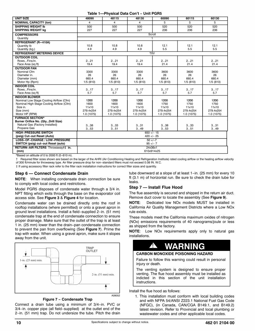
To remove downflow return and supply knockout covers, breakfront and right side connecting tabs with a screwdriver andhammer. Push cover down to break rear and left side tabs.NOTE: These panels are held in place with tabs similar to anelectrical knockout. Reinstall horizontal duct covers (seeFigure 9) shipped on unit from factory. Insure openings are airand watertight.
NOTE: The design and installation of the duct system must bein accordance with the standards of the NFPA for installation ofnonresidence−type air conditioning and ventilating systems,NFPA 90A or residence−type, NFPA 90B; and/or local codesand ordinances.
Horizontal Duct Covers
A09076
BasepanDownflow(Vertical)SupplyKnockout
BasepanDownflow (Vertical)ReturnKnockout
A09077
Figure 9 − Supply and Return Duct OpeningAdhere to the following criteria when selecting, sizing, andinstalling the duct system:
1. Units are shipped for horizontal duct installation (byremoving duct covers).
2. Select and size ductwork, supply−air registers, andreturn−air grilles according to American Society ofHeating, Refrigeration and Air Conditioning Engineers(ASHRAE) recommendations.
3. Use flexible transition between rigid ductwork and unit toprevent transmission of vibration. The transition may bescrewed or bolted to duct flanges. Use suitable gasketsto ensure weather−tight and airtight seal.
4. All units must have field−supplied filters or accessoryfilter rack installed in the return−air side of the unit.Recommended sizes for filters are shown in Table 1.
5. Size all ductwork for maximum required airflow (eitherheating or cooling) for unit being installed. Avoid abruptduct size increases or decreases or performance may beaffected.
6. Adequately insulate and weatherproof all ductworklocated outdoors. Insulate ducts passing through

462 01 2104 00 13Specifications subject to change without notice.
unconditioned space, and use vapor barrier inaccordance with latest issue of Sheet Metal and AirConditioning Contractors National Association(SMACNA) and Air Conditioning Contractors of America(ACCA) minimum installation standards for heating andair conditioning systems. Secure all ducts to buildingstructure.
7. Flash, weatherproof, and vibration isolate all openings inbuilding structure in accordance with local codes andgood building practices.
Step 10 — Install Electrical Connections
ELECTRICAL SHOCK HAZARD
Failure to follow this warning could result in personalinjury or death.
The unit cabinet must have an uninterrupted,unbroken electrical ground. This ground may consistof an electrical wire connected to the unit groundscrew in the control compartment, or conduitapproved for electrical ground when installed inaccordance with NFPA 70 (NEC) (latest edition) (inCanada, Canadian Electrical Code CSA C22.1) andlocal electrical codes.
! WARNING
UNIT COMPONENT DAMAGE HAZARD
Failure to follow this caution may result in damage tothe unit being installed.1. Make all electrical connections in accordance with
NFPA 70 (NEC) (latest edition) and local electricalcodes governing such wiring. In Canada, allelectrical connections must be in accordance withCSA standard C22.1 Canadian Electrical CodePart 1 and applicable local codes. Refer to unitwiring diagram.
2. Use only copper conductor for connectionsbetween field−supplied electrical disconnect switchand unit. DO NOT USE ALUMINUM WIRE.
3. Be sure that high−voltage power to unit is withinoperating voltage range indicated on unit ratingplate. On 3−phase units, ensure phases arebalanced within 2 percent. Consult local powercompany for correction of improper voltage and/orphase imbalance.
4. Insulate low−voltage wires for highest voltagecontained within conduit when low−voltage controlwires are in same conduit as high−voltage wires.
5. Do not damage internal components when drillingthrough any panel to mount electrical hardware,conduit, etc.
! CAUTION
High−Voltage ConnectionsWhen routing power leads into unit, use only copper wirebetween disconnect and unit. The high voltage leads should bein a conduit until they enter the duct panel; conduit terminationat the duct panel must be watertight.The unit must have a separate electrical service with afield−supplied, waterproof disconnect switch mounted at, orwithin sight from, the unit. Refer to the unit rating plate, NECand local codes for maximum fuse/circuit breaker size andminimum circuit amps (ampacity) for wire sizing.
The field−supplied disconnect switch box may be mounted onthe unit over the high−voltage inlet hole when the standardpower and low−voltage entry points are used (See Figure 3and Figure 4 for acceptable location).NOTE: Field supplied disconnect switch box should bepositioned so that it does not cover up any of the unit gascombustion supply air louvers.
See unit wiring label (Figure 14, Figure 16 and Figure 17)and Figure 10 for reference when making high voltageconnections. Proceed as follows to complete the high−voltageconnections to the unit.Single phase units:
1. Run the high−voltage (L1, L2) and ground lead into thecontrol box.
2. Connect ground lead to chassis ground connection.3. Locate the black and yellow wires connected to the line
side of the contactor (if equipped).4. Connect field L1 to black wire from connection 11 of the
compressor contactor.5. Connect field wire L2 to yellow wire from connection 23
of the compressor contactor.Three−phase units:
1. Run the high−voltage (L1, L2, L3) and ground lead intothe control box.
2. Connect ground lead to chassis ground connection.3. Locate the black and yellow wires connected to the line
side of the contactor (if equipped).4. Connect field L1 to black wire from connection 11 of the
compressor contactor.5. Connect field wire L3 to yellow wire from connection 13
of the compressor contactor.6. Connect field wire L2 to blue wire from compressor.
Special Procedures for 208−v Operation
ELECTRICAL SHOCK HAZARD
Failure to follow this warning could result in personalinjury or death.
Make sure the power supply to the unit is switchedOFF and install lockout tag. before making any wiringchanges. With disconnect switch open, move blackwire from transformer (3/16 in. [4.8 mm]) terminalmarked 230 to terminal marked 208. This retapstransformer to primary voltage of 208 vac.
! WARNING
ELECTRICAL SHOCK FIRE/EXPLOSION HAZARD
Failure to follow this warning could result in personalinjury or death and property damage.
Before making any wiring changes, make sure thegas supply is switched off first. Then switch off thepower supply to the unit and install lockout tag.
! WARNING
Control Voltage ConnectionsDo not use any type of power−stealing thermostat. Unit controlproblems may result.Use no. 18 American Wire Gage (AWG) color−coded, insulated(35�C minimum) wires to make the control voltage connectionsbetween the thermostat and the unit. If the thermostat islocated more than 100 ft (30.5 m) from the unit (as measured

14 462 01 2104 00Specifications subject to change without notice.
along the control voltage wires), use no. 16 AWG color−coded,insulated (35�C minimum) wires.
Standard ConnectionRun the low−voltage leads from the thermostat, through theinlet hole, and into unit low−voltage splice box.Locate eight 18−gage wires leaving control box. Theselow−voltage connection leads can be identified by the colorsred, green, yellow, brown, blue, and white (See Figure 10).Ensure the leads are long enough to be routed into thelow−voltage splice box (located below right side of control box).Route leads through hole in bottom of control box and makelow−voltage connections (See Figure 10). Secure all cut wires,so that they do not interfere with operation of unit.
POWERSUPPLY
FIELD-SUPPLIEDFUSED DISCONNECT
HIGH VOLTAGEPOWER LEADS(SEE UNIT WIRINGLABEL)
EQUIP GR
3-PHASE SHOWN1-PHASE USES TWO POWER LEADS
SPLICE BOX
LOW-VOLTAGEPOWER LEADS(SEE UNITWIRING LABEL)
WHT(W1)W/W1
YEL (Y)Y1/Y
GGRN(G)
RED(R)
BRN(C)
BLU(DH)
R
C
DH
Y2
W2
PINK(Y2)
BLK(W2)
CONTROL BOX
(
THERMOSTAT(TYPICAL)
L13P007
Figure 10 − High− and Control−Voltage Connections
IMPORTANT: Dehumidification control must opencontrol circuit on humidity rise above set point.Use of the dehumidification cooling fan speed requiresuse of either a 24 VAC dehumidistat or a thermostatwhich includes control of a 24 VAC dehumidistatconnection. In either case, the dehumidification controlmust open the control circuit on humidity rise above thedehumidification set point.
Heat Anticipator Setting(Electro−Mechanical Thermostats only)The room thermostat heat anticipator must be properlyadjusted to ensure proper heating performance. Set the heatanticipator, using an ammeter between the W1 and R terminalsto determine the exact required setting.NOTE: For thermostat selection purposes, use 0.18 amp forthe approximate required setting. Failure to make a proper heatanticipator adjustment will result in improper operation,discomfort to the occupants of the conditioned space, andinefficient energy utilization; however, the required setting maybe changed slightly to provide a greater degree of comfort for aparticular installation.
Transformer ProtectionThe transformer is of the energy−limiting type, however a directshort will likely blow a secondary fuse. If an overload or short ispresent, correct overload condition and check for blown fuse on
Indoor Fan board or Integrated Gas Controller. Replace fuse asrequired with correct size and rating.
PRE−START−UP
ENVIRONMENTAL, FIRE, EXPLOSION,ELECTRICAL SHOCK HAZARD
Failure to follow this warning could result in personalinjury or death.1. Follow recognized safety practices and wear
protective goggles when checking or servicingrefrigerant system.
2. Do not operate compressor or provide any electricpower to unit unless compressor plug is in placeand secured.
3. Do not remove compressor plug until all electricalsources are disconnected and tagged.
4. Relieve and recover all refrigerant from systembefore touching or disturbing compressor plug ifrefrigerant leak is suspected around compressorterminals.
5. Never attempt to repair soldered connection whilerefrigerant system is under pressure.
6. Do not use torch to remove any component.System contains oil and refrigerant under pressure.To remove a component, wear protective gogglesand proceed as follows:
a. Shut off electrical power to unit and installlockout tag.
b. Relieve and reclaim all refrigerant fromsystem using both high− and low−pressureports.
c. Cut component connecting tubing withtubing cutter and remove component fromunit.
d. Carefully unsweat remaining tubing stubswhen necessary. Oil can ignite whenexposed to torch flame.
! WARNING
Use the Start−Up Checklist supplied at the end of this book andproceed as follows to inspect and prepare the unit for initialstart−up:
1. Remove access panels (see Figure 20).2. Read and follow instructions on all DANGER, WARNING,
CAUTION, and INFORMATION labels attached to, orshipped with unit.
3. Make the following inspections:a. Inspect for shipping and handling damage, such as
broken lines, loose parts, disconnected wires, etc.b. Inspect for oil at all refrigerant tubing connections and
on unit base. Detecting oil generally indicates arefrigerant leak.
c. Leak−test all refrigerant tubing connections usingelectronic leak detector, or liquid−soap solution. If arefrigerant leak is detected, see following Check forRefrigerant Leaks section.
d. Inspect all field− and factory−wiring connections. Besure that connections are completed and tight.
e. Ensure wires do not touch refrigerant tubing or sharpsheet metal edges.
f. Inspect coil fins. If damaged during shipping andhandling, carefully straighten fins with a fin comb.

462 01 2104 00 15Specifications subject to change without notice.
FIRE, EXPLOSION HAZARD
Failure to follow this warning could result in personalinjury, death or property damage.
Do not purge gas supply into the combustionchamber. Do not use a match or other open flame tocheck for gas leaks.Use a commercially available soap solution madespecifically for the detection of leaks to check allconnections. A fire or explosion may result causingproperty damage, personal injury or loss of life.
! WARNING
4. Verify the following conditions:a. Make sure gas line is free of air. Before lighting the
unit for the first time, perform the following with thegas valve in the OFF position:
NOTE: If the gas supply pipe was not purged beforeconnecting the unit, it will be full of air. It is recommended thatthe ground joint union be loosened, and the supply line beallowed to purge until the odor of gas is detected. Never purgegas lines into a combustion chamber. Immediately upondetection of gas odor, retighten the union. Allow 5 minutes toelapse, then light unit.
b. Make sure that outdoor−fan blade is correctlypositioned in the fan orifice.
c. Make sure that air filter(s) is in place.d. Make sure that condensate drain trap is filled with
water to ensure proper drainage.e. Make sure that all tools and miscellaneous loose
parts have been removed.
START−UPStep 1 — Check for Refrigerant LeaksProceed as follows to locate and repair a refrigerant leak and tocharge the unit:
1. Locate leak and make sure that refrigerant systempressure has been relieved and reclaimed from bothhigh− and low−pressure ports.
2. Repair leak following accepted practices.NOTE: Install a filter drier whenever the system has beenopened for repair.
3. Add a small charge of R−410A refrigerant vapor tosystem and leak−test unit.
4. Recover refrigerant from refrigerant system andevacuate to 500 microns if no additional leaks are found.
5. Charge unit with R−410A refrigerant, using an accuratescale. Refer to unit rating plate for required charge.
Step 2 — Start−up Heating and Make AdjustmentsComplete the required procedures given in the Pre−Start−Upsection before starting the unit. Do not jumper any safetydevices when operating the unit. Make sure that burner orificesare properly aligned. Unstable operation my occur when theburner orifices in the manifold are misaligned.Follow the lighting instructions on the heating section operationlabel (located on the inside of the control access panel) to startthe heating section.NOTE: Make sure that gas supply has been purged, and thatall gas piping has been checked for leaks.
Pipe PlugManifold
A07679
Figure 11 − Burner Assembly
MANIFOLD
BURNER
BURNER FLAME
C99021
Figure 12 − Monoport Burner
Check Heating ControlStart and check the unit for proper heating control operation asfollows (see furnace lighting instructions located on the insideof the control access panel):
1. Place room thermostat SYSTEM switch in the HEATposition and the fan switch in AUTO position.
2. Set the heating temperature control setting severaldegrees higher than the room temperature reading.
3. The induced−draft motor will always start on high speedfor the ignition sequence, regardless of the heating stagecalled.
4. After a pre−purge time of 15 sec with the induced−draftmotor on high speed, the sparker will be energized for3−to−8 sec, and the gas valve will be energized on lowstage. If the burners do not light, there is a 20−sec delaybefore another ignition attempt. If the burners still do notlight by the 4th consecutive ignition attempt, there is alockout. To reset the lockout, break the 24−v power toW1 and W2.
5. Once flame is established the integrated gas unitcontroller (IGC) will look for 24−v power to W1 and W2. Ifthere is 24−v power to W1 only, the IGC will switch theinduced−draft motor down to low speed and maintain lowstage on the gas valve. If there is 24−v power to both W1and W2, the IGC will maintain the induced−draft motor onhigh speed and switch the gas valve to high stage.
6. With the desired temperature set several degrees higherthan the room temperature, most thermostats willenergize low and high stage. Verify that the gas valve is

16 462 01 2104 00Specifications subject to change without notice.
energized on high stage and the induced−draft motor ison high speed.
7. Verify proper operation of low stage (induced−draft motoron low speed and gas valve on high stage) by turningthe heating temperature control setting down until thedesired temperature is 1 degree above roomtemperature. Most thermostats will energize low stageonly with a 1 degree differential.
8. The evaporator fan will turn on 30 sec after the flame hasbeen established. If there is 24−v power to W1 only, thefan will run on low heat speed. If there is 24−v power toW1 and W2, the fan will run on high heat speed. Oncethe heating coll is satisfied, the IGC will turn the fan offafter a field−selectable fan delay of 90, 120, 150, or 180sec is completed.
Check Gas InputCheck gas input and manifold pressure after unit start−up (SeeTable 4. If adjustment is required proceed as follows:
� The rated gas inputs shown in Table 4 are foraltitudes from sea level to 2000 ft (610 m) above sealevel. These inputs are based on natural gas with aheating value of 1025 Btu/ft3 at 0.60 specific gravity, orpropane gas with a heating value of 2500 Btu/ft3 at 1.5specific gravity.
IN THE U.S.A.:The input rating for altitudes above 2,000 ft (610 m) must bereduced by 4% for each 1,000 ft (305 m) above see level.For installations below 2,000 ft (610 m), refer to the unit ratingplate.For installations above 2,000 ft (610 m). multiply the input onthe rating plate by the derate multiplier in Table 3 for correctinput rate.
Table 3 – Altitude Derate Multiplier for U.S.A.*
ALTITUDE FT (M) PERCENT OF DERATEDERATE MULTIPLIER
FACTOR�
0-2000(0-610)
0 1.00
2001-3000*(610-914)
8-12 0.90
3001-4000(915-1219)
12-16 0.86
4001-5000(1220-1524)
16-20 0.82
5001-6000(1524 -1829)
20-24 0.78
6001-7000(1829-2134)
24-28 0.74
7001-8000(2134-2438)
28-32 0.70
8001-9000(2439-2743)
32-36 0.66
9001-10,000(2744-3048)
36-40 0.62
*In Canada see Canadian Altitude Adjustment.�Derate multiplier factors are based on midpoint altitude for altitude range.
IN CANADA:The input rating for altitudes from 2,000 (610 m) to 4,500 ft(1372 m) above sea level must be derated 10% by anauthorized Gas Conversion Station or Dealer.EXAMPLE:90,000 Btu/hr Input Furnace Installed at 4300 ft.
Furnace Input Rate atSea Level
X Derate MultiplierFactor
= Furnace Input Rate atInstallation Altitude
90,000 X 0.90 = 81,000
When the gas supply being used has a different heating valueor specific gravity, refer to national and local codes, or contactyour distributor to determine the required orifice size.
UNIT DAMAGE HAZARD
Failure to follow this caution may result in reducedunit and/or component life.Do Not redrill an orifice. Improper drilling (burrs,out−of−round holes, etc.) can cause excessive burnernoise and misdirection of burner flame. If orifice holeappears damaged or it is suspected to have beenredrilled, check orifice hole with a numbered drill bit ofcorrect size.
! CAUTION
Adjust Gas InputThe gas input to the unit is determined by measuring the gasflow at the meter or by measuring the manifold pressure.Measuring the gas flow at the meter is recommended fornatural gas units. The manifold pressure must be measured todetermine the input of propane gas units.Measure Gas Flow (Natural Gas Units)Minor adjustment to the gas flow can be made by changing themanifold pressure(s). The manifold pressure(s) must bemaintained between 3.2 and 3.8 IN. W.C. for high stage andbetween 1.4 and 2.0 IN. W.C. for low stage.
REGULATOR COVER SCREW
PLASTIC ADJUST SCREW
LOW STAGE GAS PRESSURE REGULATOR ADJUSTMENT
MANIFOLDPRESSURE TAP
INLETPRESSURE TAP
ON/OFF SWITCH
REGULATOR SPRING
HIGH STAGE GAS PRESSURE REGULATOR ADJUSTMENT
1/2˝ NPT OUTLET
1/2˝ NPT INLET
A04167
Figure 13 − Two−Stage Gas Valve
If larger adjustments are required, change main burner orificesfollowing the recommendations of national and local codes.NOTE: All other appliances that use the same meter must beturned off when gas flow is measured at the meter.Proceed as follows:
1. Turn off gas supply to unit.2. Remove pipe plug on manifold (See Figure 11) and
connect manometer. Turn on gas supply to unit.3. Record number of seconds for gas meter test dial to
make one revolution.4. Divide number of seconds in Step 3 into 3600 (number of
seconds in one hr).5. Multiply result of Step 4 by the number of cubic feet (cu
ft) shown for one revolution of test dial to obtain cubicfeet (cu ft) of gas flow per hour.
6. Multiply result of Step 5 by Btu heating value of gas toobtain total measured input in Btuh. Compare this valuewith heating input shown in Table 4 (Consult the localgas supplier if the heating value of gas is not known).

462 01 2104 00 17Specifications subject to change without notice.
EXAMPLE: Assume that the size of test dial is 1 cu ft, onerevolution takes 32 sec and the heating value of the gas is1050 Btu/ft3. Proceed as follows:
1. 32 sec to complete one revolution.2. 3600 ÷ 32 = 112.5.3. 112.5 x 1 =112.5 ft3 of gas flow/hr.4. 112.5 x 1050 = 118,125 Btuh input.
If the desired gas input is 115,000 Btuh, only a minor change inthe manifold pressure is required.Observe manifold pressure(s) and proceed as follows to adjustgas input(s):
1. Remove regulator cover screw(s) over plastic adjustmentscrew(s) on gas valve (Figure 13).
2. Turn the high stage plastic adjustment screw clockwiseto increase gas input and counterclockwise to decreaseinput (see Figure 13). Manifold pressure must bebetween 3.2 and 3.8 IN. W.C. for high stage.
3. Replace high stage regulator cover screw on gas valve(see Figure 13).
4. Turn the low stage plastic adjustment screw clockwise toincrease gas input and counterclockwise to decreaseinput (see Figure 13). Low stage manifold pressure mustbe between 1.4 and 2.0 IN. W.C.
NOTE: Low stage manifold pressure must be adjusted afterhigh stage manifold pressure is already adjusted.
5. Replace low stage regulator cover screw(s) on gas valve(see Figure 13).
6. Turn off gas supply to unit. Remove manometer frompressure tap and replace pipe plug on manifold (seeFigure 11). Turn on gas and check for leaks
FIRE AND UNIT DAMAGE HAZARD
Failure to follow this warning could result in personalinjury or death and/or property damage.
Unsafe operation of the unit may result if manifoldpressure is outside this range.
! WARNING
Measure Manifold Pressure (Propane Units)Refer to propane kit installation instructions for properlychecking gas input.NOTE: For installations below 2,000 ft (610 m), refer to the unitrating plate for proper propane conversion kit. For installationsabove 2,000 ft (610 m), contact your distributor for properpropane conversion kit.
Check Burner FlameWith control access panel (see Figure 20) removed, observethe unit heating operation. Watch the burner flames to see ifthey are light blue and soft in appearance, and that the flamesare approximately the same for each burner. Propane will haveblue flame (See Figure 12). Refer to the Maintenance sectionfor information on burner removal.
Table 4 – Heating Inputs 208/230 VAC Models
HEATING INPUT(BTUH)
NUMBER OF
GAS SUPPLY PRESSURE (IN. W.C.) MANIFOLD PRESSURE NUMBER OF
ORIFICESNatural� Propane*�
MANIFOLD PRESSURE (IN. W.C.)
ORIFICES
Min Max Min Max Natural� Propane*†
40,000 2 4.0 13.0 11.0 13.0 3.2∼3.8 10.0∼11.0
60,000 2 4.0 13.0 11.0 13.0 3.2∼3.8 10.0∼11.0
90,000 3 4.0 13.0 11.0 13.0 3.2∼3.8 10.0∼11.0
115,000 3 4.0 13.0 11.0 13.0 3.2∼3.8 10.0∼11.0
130,000 3 4.0 13.0 11.0 13.0 3.2∼3.8 10.0∼11.0*When a unit is converted to propane, different size orifices must be used. See separate, natural−to−propane conversion kit instructions.�Based on altitudes from sea level to 2000 ft (610 m) above sea level. In U.S.A. for altitudes above 2000 ft (610 m), reduce input rating 4 percent for each additional 1000ft (305 m) above sea level. In Canada, from 2000 ft (610 m) above sea level to 4500 ft (1372 m) above sea level, derate the unit 10 percent.

18 462 01 2104 00Specifications subject to change without notice.
A13018
Figure 14 − 208/230−1−60 Connection Wiring Diagram Gas Inputs 40, 60, 90 K Btu/hr

462 01 2104 00 19Specifications subject to change without notice.
A13019
Figure 14 Cont. − 208/230−1−60 Ladder Wiring Diagram Gas Inputs 40, 60, 90 K Btu/hr

20 462 01 2104 00Specifications subject to change without notice.
A13020
Figure 15 − 208/230−1−60 Connection Wiring Diagram Gas Inputs 115, 130 K Btu/hr
462 01 2104 00 21Specifications subject to change without notice.
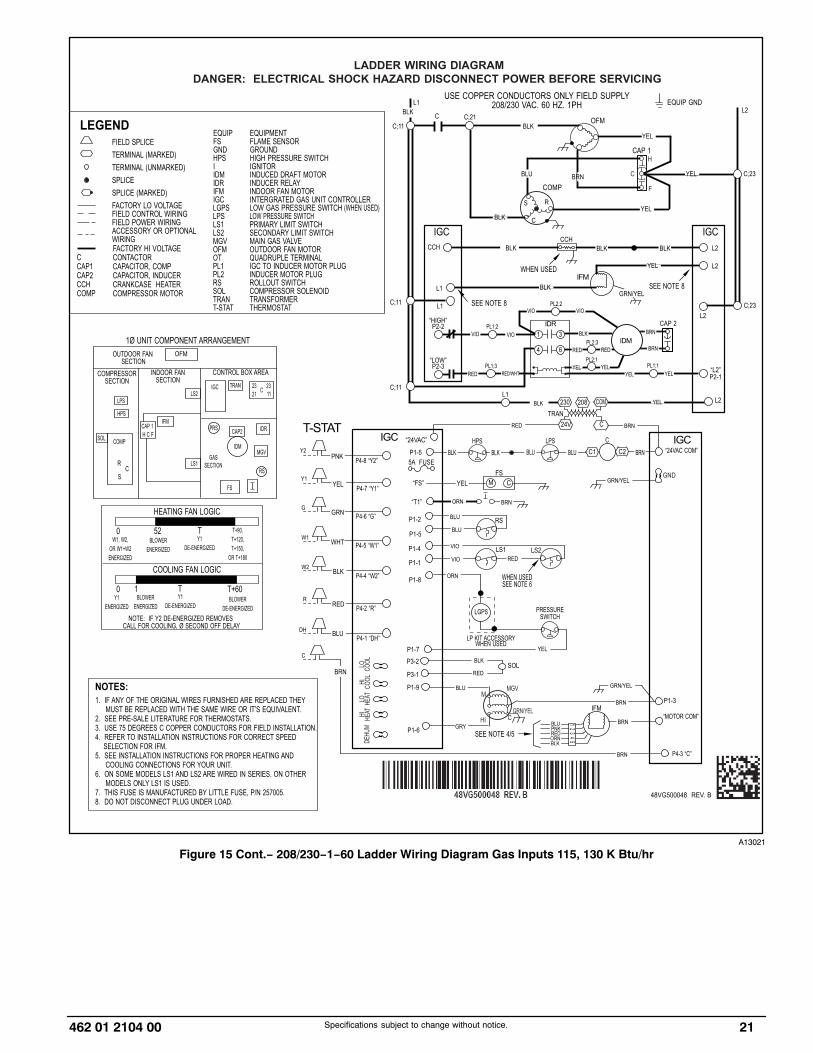
A13021
Figure 15 Cont.− 208/230−1−60 Ladder Wiring Diagram Gas Inputs 115, 130 K Btu/hr

22 462 01 2104 00Specifications subject to change without notice.
A13022
Figure 16 − 208/230−3−60 Connection Wiring Diagram Gas Inputs 40, 60, 90 K Btu/hr

462 01 2104 00 23Specifications subject to change without notice.
A13023
Figure 16 Cont. − 208/230−3−60 Ladder Wiring Diagram Gas Inputs 40, 60, 90 K Btu/hr

24 462 01 2104 00Specifications subject to change without notice.
A13024
Figure 17 − 208/230−3−60 Connection Wiring Diagram Gas Inputs 115, 130 K Btu/hr

462 01 2104 00 25Specifications subject to change without notice.
A13025
Figure 17 Cont. − 208/230−3−60 Ladder Wiring Diagram Gas Inputs 115, 130 K Btu/hr

26 462 01 2104 00Specifications subject to change without notice.
Normal OperationAn LED (light−emitting diode) indicator is provided on theintegrated gas unit controller (IGC) to monitor operation. TheIGC is located by removing the control access panel (seeFigure 20). During normal operation, the LED is continuouslyon (See Table 5 for error codes).
Table 5 – LED IndicationsSTATUS CODE LED INDICATION
Normal Operation2 OnNo Power or Hardware Failure Off
Limit Switch Fault 2 FlashesFlame Sense Fault 3 Flashes
Four Consecutive Limit Switch Faults 4 FlashesIgnition Lockout Fault 5 FlashesPressure Switch Fault 6 FlashesRollout Switch Fault 7 FlashesInternal Control Fault 8 Flashes
Temporary 1 hr auto reset1 9 Flashes
NOTES:1.This code indicates an internal processor fault that will reset itself in one hr.Fault can be caused by stray RF signals in the structure or nearby. This is a ULrequirement.2. LED indicates acceptable operation. Do not change ignition control board.3. When W is energized the burners will remain on for a minimum of 60 sec.4. If more than one error code exists they will be displayed on the LED insequence.
Airflow and Temperature Rise The heating section for each size unit is designed andapproved for heating operation within the temperature−riserange(s) stamped on the unit rating plate.Tables 9 show the approved temperature rise range for eachheating input and stage, and the air delivery cfm at varioustemperature rises for a given external static pressure. Theheating operation airflow must produce a temperature rise thatfalls within the approved range for each heating stage.Refer to Indoor Airflow and Airflow Adjustments section toadjust heating airflow when required.
Heating Sequence of Operation(See Figure 14, Figure 16, Figure 17 and unit wiring label.)On a call for low stage heating, terminal W1 on the thermostatis energized. On a call for high stage heating both terminals W1and W2 are energized. Regardless of the stage of the heatingcall, the induced−draft motor is turned on to high speed for a 15sec pre−purge time. After the pre−purge, when the pressureswitch senses that sufficient combustion air is being moved bythe induced−draft motor, the ignition sequence begins. The IGCwill energize the sparker and the low stage gas valve solenoid.Upon sensing flame, the IGC will check the heating call. If W2is not energized, the IGC will drop the induced−draft motor tolow speed and maintain the gas valve on low stage. If W2 isenergized, the IGC will maintain the induced−draft motor onhigh speed and energize the high stage gas valve solenoid.Thirty sec after flame is sensed the IGC will turn on theevaporator fan motor. If W2 is not energized, the evaporator fanmotor will run on low heat speed. If W2 is energized, theevaporator fan motor will run on high heat speed. After the callfor heat is satisfied, the IGC will run the evaporator fan motoran additional field−selectable time of 90, 120, 150, or 180 secbefore shutting the evaporator fan motor off.
Limit SwitchesNormally closed limit switch(es) (LS) complete the controlcircuit. Should the leaving−air temperature rise above themaximum allowable temperature, the limit switch opens and thecontrol circuit “breaks.” Any interruption in the control circuitinstantly closes the gas valve and stops gas flow to theburners. The blower motor continues to run until LS resets.
When the air temperature at the limit switch drops to thelow−temperature setting of the limit switch, the switch closesand completes the control circuit. The direct−spark ignitionsystem cycles and the unit returns to normal heating operation.
Rollout SwitchThe function of the rollout switch is to close the main gas valvein the event of flame rollout. The switch is located above themain burners. When the temperature at the rollout switchreaches the maximum allowable temperature, the control circuittrips, closing the gas valve and stopping gas flow to theburners. The indoor (evaporator) fan motor (IFM) and induceddraft motor continue to run until switch is reset. The IGC LEDwill display FAULT CODE 7.
Step 3 — Start−up Cooling and Make AdjustmentsComplete the required procedures given in the Pre−Start−Upsection before starting the unit. Do not jumper any safetydevices when operating the unit. Do not operate thecompressor when the outdoor temperature is below 40°F(4.4°C) (unless accessory low−ambient kit is installed). Do notrapid−cycle the compressor. Allow 5 minutes between oncycles to prevent compressor damage.
Checking Cooling Control OperationStart and check the unit for proper control operation as follows:
1. Place room thermostat SYSTEM switch or MODE controlin OFF position. Observe that blower motor starts whenFAN mode is placed in FAN ON position and shuts downwhen FAN MODE switch is placed in AUTO position.
2. Thermostat:On a typical two stage thermostat, when the roomtemperature rises 1 or 2 degrees above the coolingcontrol setting of the thermostat, the thermostatcompletes the circuit between thermostat terminal R andterminals Y1, and G. These completed circuits throughthe thermostat connect the contactor coil (C) (throughunit wire Y1) and indoor fan board (through unit wire G)across the 24−v. secondary of transformer (TRAN).On a typical two stage thermostat, when the roomtemperature is several degrees above the cooling controlsetting of the thermostat, the thermostat completes thecircuit between terminal R and terminals T1, Y2 , and G.
3. When using an automatic changeover room thermostatplace both SYSTEM or MODE control and FAN modestitches in AUTO positions. Observe that unit operates inCooling mode when temperature control is set to “call forCooling” (below room temperature).
NOTE: Once the compressor has started and then hasstopped, it should not be started again until 5 minutes haveelapsed.
IMPORTANT: Three−phase, scroll compressors aredirection oriented. Unit must be checked to ensureproper compressor 3−phase power lead orientation. Ifnot corrected within 5 minutes, the internal protector willshut off the compressor. The 3−phase power leads tothe unit must be reversed to correct rotation. Whenturning backwards, the difference between compressorsuction and discharge pressures will be minimal.
Checking and Adjusting Refrigerant ChargeThe refrigerant system is fully charged with R−410A refrigerantand is tested and factory sealed. Allow system to operate aminimum of 15 minutes before checking or adjusting charge.NOTE: Adjustment of the refrigerant charge is not requiredunless the unit is suspected of not having the proper R−410Acharge.A subcooling chart is attached to the inside of the compressoraccess panel. (See Table 8 and Figure 20) The chart includes

462 01 2104 00 27Specifications subject to change without notice.
the required liquid line temperature at given discharge linepressures and outdoor ambient temperatures for high stagecooling.An accurate thermocouple− or thermistor−type thermometer,and a gauge manifold are required when using the subcoolingcharging method for evaluating the unit charge. Do not usemercury or small dial−type thermometers because they are notadequate for this type of measurement.
UNIT DAMAGE HAZARD
Failure to follow this caution may result in unitdamage.When evaluating the refrigerant charge, an indicatedadjustment to the specified factory charge mustalways be very minimal. If a substantial adjustment isindicated, an abnormal condition exists somewhere inthe cooling system, such as insufficient airflow acrosseither coil or both coils.
! CAUTION
IMPORTANT: When evaluating the refrigerant charge,an indicated adjustment to the specified factory chargemust always be very minimal. If a substantial adjustmentis indicated, an abnormal condition exists somewhere inthe cooling system, such as insufficient airflow acrosseither coil or both coils.Proceed as follows:
1. Remove caps from low− and high−pressure servicefittings.
2. Using hoses with valve core depressors, attach low− andhigh−pressure gauge hoses to low− and high−pressureservice fittings, respectively.
3. Start unit in high stage cooling mode and let unit run untilsystem pressures stabilize.
4. Measure and record the following:a. Outdoor ambient−air temperature (°F [°C] db).b. Liquid line temperature (°F [°C]).c. Discharge (high−side) pressure (psig).d. Suction (low−side) pressure (psig) (for reference
only).5. Using “Subcooling Charging Charts,” compare
outdoor−air temperature(°F [°C] db) with the dischargeline pressure (psig) to determine desired systemoperating liquid line temperature (See Table 8).
6. Compare actual liquid line temperature with desiredliquid line temperature. Using a tolerance of ± 2°F(±1.1°C), add refrigerant if actual temperature is morethan 2°F (1.1°C) higher than proper liquid linetemperature, or remove refrigerant if actual temperatureis more than 2°F (1.1°C) lower than required liquid linetemperature.
NOTE: If the problem causing the inaccurate readings is arefrigerant leak, refer to the Check for Refrigerant Leakssection.
Indoor Airflow and Airflow Adjustments
UNIT OPERATION HAZARD
Failure to follow this caution may result in unitdamage.
For cooling operation, the recommended airflow is350 to 450 cfm for each 12,000 Btuh of rated coolingcapacity. For heating operation, the airflow mustproduce a temperature rise that falls within the rangestamped on the unit rating plate.
CAUTION!
NOTE: Be sure that all supply−and return−air grilles are open,free from obstructions, and adjusted properly.
ELECTRICAL SHOCK HAZARD
Failure to follow this warning could result in personalinjury or death.
Disconnect electrical power to the unit and installlockout tag before changing blower speed(s).
! WARNING
This unit has independent fan speeds for low stage cooling andhigh stage cooling. In addition all models have thefield−selectable capability to run an enhanced dehumidification(’DHUM’) speed on high stage cooling (as low as 320CFM perton). Coupled with the improved dehumidification associatedwith low stage cooling, the DHUM speed allows for a completedehumidification solution independent of cooling stage. allmodels also have independent fan speeds for low stage gasheating and high stage gas heating. Table 6 shows theoperation modes and the associated fan speeds with eachmode:
Table 6 – Operation Modes and Fan Speeds 208/230 VAC Models
OPERATION MODEFAN SPEED TAPCONNECTION
Low Stage Gas Heating LO HEAT
High Stage Gas Heating HI HEAT
Low Stage Cooling LO COOL
High Stage Cooling HI COOL
High Stage Enhanced Dehumidification Cooling
DHUM
Continuous Fan LO COOL
The evaporator fan motor is factory set to provide 5 different fanspeeds to choose from for the various operation modes. Allmodels are factory−shipped with 4 speed wires connected withone spare speed wire available. The fan speed wires arecolor−coded as follows:
Table 7 – Color Coding for Indoor Fan Motor Leads
Black = High Speed
Orange = Med-High Speed
Red = Med Speed
Pink = Med-Low Speed
Blue = Low Speed

28 462 01 2104 00Specifications subject to change without notice.
Selection of Proper Fan Speeds for Operation Modes:NOTE: All models are factory−shipped for nominal high stageand low stage cooling airflow operation at minimum externalstatic pressure. Many models are factory−shipped for nominalhigh stage and/or low stage gas heating airflow at minimumexternal static pressure. Table 9 provides airflow data forhigher external static pressures.
Low Stage Gas Heating: Table 9 shows the suitability of eachspeed for a given external static pressure for low stage gasheating. Any speed/static combination that is outside the riserange is marked “NA” and must not be used. The unit mustoperate within the low stage gas heat rise range printed on therating plate. Connect the chosen fan speed wire to “LO HEAT”connection on the IGC Board (see Figure 18).High Stage Gas Heating: Table 9 shows the suitability of eachspeed for a given external static pressure for high stage gasheating. Any speed/static combination that is outside the riserange is marked “NA” and must not be used. The unit mustoperate within the high stage gas heat rise range printed on therating plate. Connect the chosen fan speed wire to “HI HEAT”connection on the IGC Board (see Figure 18).Low Stage Cooling (All models): Using Tables 10, 11, and12, and the nominal airflow for low stage cooling (Table 1) findthe external static pressure drops for wet coil, economizer, andfilter, and add them to dry coil measured on the system. Usingthis total static pressure, use Table 9 to find the airflowsavailable at the total static pressure. Connect the chosen fanspeed wire to “LO COOL” connection on the IGC Board (seeFigure 18).High Stage Cooling (All models) Using Tables 10, 11, and12, find the external static pressure drops for wet coil,economizer, and filter, and add them to dry coil measured onthe system. Using this total static pressure, use Table 9 to findthe airflows available at the total static pressure. The speedchosen must provide airflow of between 350 to 450 CFM perton of cooling. Connect the chosen fan speed wire to “HICOOL” connection on the IGC Board (See Figure 18).High Stage Enhanced Dehumidification Cooling: Using thetotal static pressure for selecting the high stage cooling speed,use Table 9 to find lower speed/airflows available at that totalstatic pressure. All airflows highlighted in Table 9 areacceptable for Dehum speed. The speed chosen must provideairflow of between 320 to 400 CFM per ton of cooling. Connectthe chosen fan speed wire to “DHUM” connection on the IGCBoard (see Figure 18).To activate the high stage enhanced dehumidification coolingmode, the shunt jumper in Figure 18 must be moved from theNo DH to DH selection (See Figure 18, close up).Continuous Fan (All models): Continuous fan speed is thesame speed as Low Stage Cooling.Using the Same Fan Speed for More than One Mode: Somefan speeds are ideal for more than one mode of operation. It is
permissible to use a field−supplied jumper wire to connect onespeed tap wire to two or more speed connections on theignition board (IGC). Jumper wires must use 18 AWG wire withat least 2/64” insulation.
Cooling Sequence of Operationa. Continuous Fan
(1.) Thermostat closes circuit R to G energizing theblower motor for continuous fan. The indoor fanis energized on low speed.
b. Cooling Mode(1.) Low Stage: Thermostat closes R to G, R to Y1.
The compressor and indoor fan are energized onlow speed. The outdoor fan is also energized.
(2.) High Stage: Thermostat closes R to G, R to Y1,R to Y2. The compressor and indoor fan areenergized on high speed. The outdoor fan is alsoenergized.
DH
DH
DH
DH
Shunt in nodehumidification
position
Shunt in dehumidificationposition
L2 L1L2 HIGH LOW CCH
P2
GN
D
MO
DEL
CEP
L13
10
94
-01
-R
T1
C9
CEB
D4
31
09
4-0
2-R
AH
SCI
SST-
A
SOL
P3
AN
SI
Z21
.20
AU
TOM
ATIC
IGN
ITIO
N
SYST
EM24
VAC
50
/60h
Z 3
50M
a M
AX
.
K3K4
T2
K5
C11
Q7 Q6D13
D12 D14JW6
D19
D28 D20R67 D18R66
D17R68
R69D16
D15K7
D11
D7
JW4
R57
C7
Q2
D26
Q3
R55R54D6
R56
R13
C8
Q1K11 D24R60
R59FS
HI
DH
UM
CO
OL
LO CO
OL
LO HEA
TH
EAT
HI
HEA
T
Pb e1
R58
R61C6
R53
K12R14R15
D25 R72R73
Z1
C5
K9D22
R2
U2D10
R65
Q4Q5
K6
C10
D27
R63R62
R64D8
JW3C4
R44
K2
D9
R43
R45
R33R30
R39R42R36R21R27
R18
R24
R32
R38R41R35R20
R17
R26
R29
R22
R22
K10
1
R7
1 JW1
MO
TOR
CO
M
D23
D21
U3
U1
AM
P3
K8
J1
F1
P4
24VA
C
24VA
C C
OM
JW11
BLOWEROFF DELAY
D3
D1
D2
D4
C1 MOV1
AN1 C2 C3
D5 JW9R1
R46R49
180
90120150
JW7
R10
R34
R4
R19
R6
R52
JW5R25
R70
R51R47
R48R5
Y2 Y1 G W1W2 C R DH
DHDH
JW8 JW10
R31
R28
R16R37
R40
R12
R11
R3
R7
R9
J2
P1
CONT
COM
HUM
K1
JW2
A13017
Figure 18 − Interface Fan Board (IFB)

462 01 2104 00 29Specifications subject to change without notice.
Table 8 – Subcooling Charging Chart
A12578
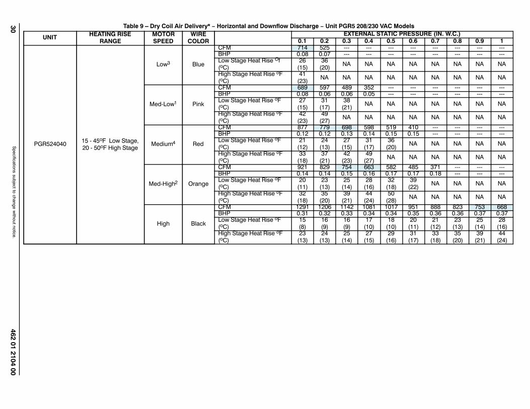
30462 01 2104 00
Specifications subject to change w
ithout notice.
Table 9 – Dry Coil Air Delivery* − Horizontal and Downflow Discharge − Unit PGR5 208/230 VAC Models
UNITHEATING RISE
RANGEMOTORSPEED
WIRECOLOR
EXTERNAL STATIC PRESSURE (IN. W.C.)
0.1 0.2 0.3 0.4 0.5 0.6 0.7 0.8 0.9 1
PGR52404015 45oF Low Stage,20 50oF High Stage
Low3 Blue
CFM 714 525 BHP 0.08 0.07 Low Stage Heat Rise Of(oC)
26(15)
36(20)
NA NA NA NA NA NA NA NA
High Stage Heat Rise oF(oC)
41(23)
NA NA NA NA NA NA NA NA NA
MedLow1 Pink
CFM 689 597 489 352 BHP 0.08 0.06 0.06 0.05 Low Stage Heat Rise oF(oC)
27(15)
31(17)
38(21)
NA NA NA NA NA NA NA
High Stage Heat Rise oF(oC)
42(23)
49(27)
NA NA NA NA NA NA NA NA
Medium4 Red
CFM 877 779 698 598 519 410 BHP 0.12 0.12 0.13 0.14 0.15 0.15 Low Stage Heat Rise oF(oC)
21(12)
24(13)
27(15)
31(17)
36(20)
NA NA NA NA NA
High Stage Heat Rise oF(oC)
33(18)
37(21)
42(23)
49(27)
NA NA NA NA NA NA
MedHigh2 Orange
CFM 921 829 754 663 582 485 371 BHP 0.14 0.14 0.15 0.16 0.17 0.17 0.18 Low Stage Heat Rise oF(oC)
20(11)
23(13)
25(14)
28(16)
32(18)
39(22)
NA NA NA NA
High Stage Heat Rise oF(oC)
32(18)
35(20)
39(21)
44(24)
50(28)
NA NA NA NA NA
High Black
CFM 1291 1206 1142 1081 1017 951 888 823 753 668BHP 0.31 0.32 0.33 0.34 0.34 0.35 0.36 0.36 0.37 0.37Low Stage Heat Rise oF(oC)
15(8)
16(9)
16(9)
17(10)
18(10)
20(11)
21(12)
23(13)
25(14)
28(16)
High Stage Heat Rise oF(oC)
23(13)
24(13)
25(14)
27(15)
29(16)
31(17)
33(18)
35(20)
39(21)
44(24)

462 01 2104 0031
Specifications subject to change w
ithout notice.
Table 9 − Dry Coil Air Delivery* − Horizontal and Downflow Discharge − Unit PGR5 208/230 VAC Models (Cont)
UNITHEATING RISE
RANGEMOTORSPEED
WIRECOLOR
EXTERNAL STATIC PRESSURE (IN. W.C.)
0.1 0.2 0.3 0.4 0.5 0.6 0.7 0.8 0.9 1
PGR52406025 55oF Low Stage,25 55oF High Stage
Low1 Blue
CFM 689 597 489 352 BHP 0.08 0.06 0.06 0.05 Low Stage Heat Rise oF(oC)
41(23)
48(27)
NA NA NA NA NA NA NA NA
High Stage Heat Rise oF(oC)
NA NA NA NA NA NA NA NA NA NA
MedLow3 Pink
CFM 777 692 583 465 318 BHP 0.09 0.10 0.10 0.11 0.12 Low Stage Heat Rise oF(oC)
37(20)
41(23)
49(27)
NA NA NA NA NA NA NA
High Stage Heat Rise oF(oC)
NA NA NA NA NA NA NA NA NA NA
Medium2 Red
CFM 921 829 754 663 582 485 371 BHP 0.14 0.14 0.15 0.16 0.17 0.17 0.18 Low Stage Heat Rise oF(oC)
31(17)
34(19)
38(21)
43(24)
49(27)
NA NA NA NA NA
High Stage Heat Rise oF(oC)
48(27)
54(30)
NA NA NA NA NA NA NA NA
MedHigh4 Orange
CFM 1229 1171 1105 1049 980 913 838 775 679 516BHP 0.28 0.30 0.30 0.31 0.32 0.33 0.33 0.34 0.34 0.33Low Stage Heat Rise oF(oC)
NA NA26
(14)27
(15)29
(16)31
(17)34
(19)37
(20)42
(23)55
(31)High Stage Heat Rise oF(oC)
36(20)
38(21)
40(22)
42(24)
45(25)
49(27)
53(29)
NA NA NA
High Black
CFM 1291 1206 1142 1081 1017 951 888 823 753 668BHP 0.31 0.32 0.33 0.34 0.34 0.35 0.36 0.36 0.37 0.37Low Stage Heat Rise oF(oC)
NA NA25
(14)26
(15)28
(16)30
(17)32
(18)35
(19)38
(21)43
(24)High Stage Heat Rise oF(oC)
34(19)
37(20)
39(22)
41(23)
44(24)
47(26)
50(28)
54(30)
NA NA

32462 01 2104 00
Specifications subject to change w
ithout notice.
Table 9 − Dry Coil Air Delivery* − Horizontal and Downflow Discharge − Unit PGR5 208/230 VAC Models (Cont)
UNITHEATING RISE
RANGEMOTORSPEED
WIRECOLOR
EXTERNAL STATIC PRESSURE (IN. W.C.)
0.1 0.2 0.3 0.4 0.5 0.6 0.7 0.8 0.9 1
PGR53004015 45oF Low Stage,20 50oF High Stage
Low3 Blue
CFM 714 525 BHP 0.08 0.07 Low Stage Heat Rise oF(oC)
26(15)
36(20)
NA NA NA NA NA NA NA NA
High Stage Heat Rise oF(oC)
41(23)
NA NA NA NA NA NA NA NA NA
MedLow1 Pink
CFM 831 765 670 586 466 299 BHP 0.11 0.12 0.12 0.13 0.13 0.14 Low Stage Heat Rise oF(oC)
23(13)
25(14)
28(16)
32(18)
40(22)
NA NA NA NA NA
High Stage Heat Rise oF(oC)
35(19)
38(21)
43(24)
50(28)
NA NA NA NA NA NA
Medium4 Red
CFM 877 779 698 598 519 410 BHP 0.12 0.12 0.13 0.14 0.15 0.15 Low Stage Heat Rise oF (oC)
21(12)
24(13)
27(15)
31(17)
36(20)
NA NA NA NA NA
High Stage Heat Rise oF(oC)
33(18)
37(21)
42(23)
49(27)
NA NA NA NA NA NA
MedHigh2 Orange
CFM 1139 1069 1012 937 870 786 724 626 512 381BHP 0.22 0.23 0.24 0.24 0.25 0.26 0.26 0.27 0.27 0.28Low Stage Heat Rise oF(oC)
17(9)
18(10)
19(10)
20(11)
22(12)
24(13)
26(14)
30(17)
37(20)
NA
High Stage Heat Rise oF(oC)
26(14)
27(15)
29(16)
31(17)
33(19)
37(21)
40(22)
47(26)
NA NA
High Black
CFM 1531 1460 1382 1301 1209 1114 1003 890 764 629BHP 0.53 0.52 0.50 0.48 0.46 0.44 0.42 0.40 0.37 0.35Low Stage Heat Rise oF(oC)
NA NA NA NA16(9)
17(9)
19(10)
21(12)
25(14)
30(17)
High Stage Heat Rise oF(oC)
NA20
(11)21
(12)22
(12)24
(13)26
(15)29
(16)33
(18)38
(21)46
(26)

462 01 2104 0033
Specifications subject to change w
ithout notice.
Table 9 − Dry Coil Air Delivery* − Horizontal and Downflow Discharge − Unit PGR5 208/230 VAC Models (Cont)
UNITHEATING RISE
RANGEMOTORSPEED
WIRECOLOR
EXTERNAL STATIC PRESSURE (IN. W.C.)
0.1 0.2 0.3 0.4 0.5 0.6 0.7 0.8 0.9 1
PGR53006025 55oF Low Stage,25 55oF High Stage
Low3 Blue
CFM 777 692 583 465 318 BHP 0.09 0.10 0.10 0.11 0.12 Low Stage Heat Rise oF(oC)
37(21)
41(23)
49(27)
NA NA NA NA NA NA NA
High Stage Heat Rise oF(oC)
NA NA NA NA NA NA NA NA NA NA
MedLow1 Pink
CFM 831 765 670 586 466 299 BHP 0.11 0.12 0.12 0.13 0.13 0.14 Low Stage Heat Rise oF(oC)
34(19)
37(21)
43(24)
49(27)
NA NA NA NA NA NA
High Stage Heat Rise oF(oC)
54(30)
NA NA NA NA NA NA NA NA NA
Medium2 Red
CFM 1139 1069 1012 937 870 786 724 626 512 381BHP 0.22 0.23 0.24 0.24 0.25 0.26 0.26 0.27 0.27 0.28Low Stage Heat Rise oF(oC)
25(14)
27(15)
28(16)
30(17)
33(18)
36(20)
39(22)
46(26)
NA NA
High Stage Heat Rise oF(oC)
39(22)
42(23)
44(24)
47(26)
51(28)
NA NA NA NA NA
MedHigh4 Orange
CFM 1229 1171 1105 1049 980 913 838 775 679 516BHP 0.28 0.30 0.30 0.31 0.32 0.33 0.33 0.34 0.34 0.33Low Stage Heat Rise oF(oC)
NA NA26
(14)27
(15)29
(16)31
(17)34
(19)37
(21)42
(23)55
(31)High Stage Heat Rise oF(oC)
36(20)
38(21)
40(22)
42(23)
45(25)
49(27)
53(29)
NA NA NA
High Black
CFM 1531 1460 1382 1301 1209 1114 1003 890 764 629BHP 0.53 0.52 0.50 0.48 0.46 0.44 0.42 0.40 0.37 0.35Low Stage Heat Rise oF(oC)
NA NA NA NA NA26
(14)28
(16)32
(18)37
(21)45
(25)High Stage Heat Rise oF(oC)
29(16)
30(17)
32(18)
34(19)
37(21)
40(22)
44(24)
50(28)
NA NA
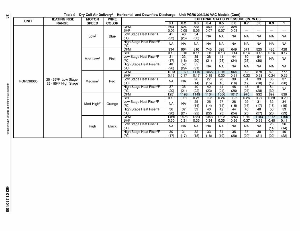
34462 01 2104 00
Specifications subject to change w
ithout notice.
Table 9 − Dry Coil Air Delivery* − Horizontal and Downflow Discharge − Unit PGR5 208/230 VAC Models (Cont)
UNITHEATING RISE
RANGEMOTORSPEED
WIRECOLOR
EXTERNAL STATIC PRESSURE (IN. W.C.)
0.1 0.2 0.3 0.4 0.5 0.6 0.7 0.8 0.9 1
PGR53606025 55oF Low Stage,25 55oF High Stage
Low3 Blue
CFM 694 624 533 460 383 328 BHP 0.05 0.05 0.06 0.07 0.07 0.08 Low Stage Heat Rise oF(oC)
41(23)
46(25)
54(30)
NA NA NA NA NA NA NA
High Stage Heat Rise oF(oC)
NA NA NA NA NA NA NA NA NA NA
MedLow1 Pink
CFM 934 864 810 745 698 649 571 525 486 428BHP 0.10 0.10 0.11 0.12 0.13 0.14 0.14 0.15 0.16 0.17Low Stage Heat Rise oF(oC)
31(17)
33(18)
35(20)
38(21)
41(23)
44(24)
50(28)
54(30)
NA NA
High Stage Heat Rise oF(oC)
48(26)
52(29)
55(31)
NA NA NA NA NA NA NA
Medium4 Red
CFM 1213 1169 1110 1065 1016 964 923 878 820 777BHP 0.16 0.17 0.17 0.19 0.20 0.21 0.22 0.23 0.24 0.25Low Stage Heat Rise oF(oC)
NA NA26
(14)27
(15)28
(16)30
(16)31
(17)33
(18)35
(19)37
(20)High Stage Heat Rise oF(oC)
37(20)
38(21)
40(22)
42(23)
44(24)
46(26)
48(27)
51(28)
54(30)
NA
MedHigh2 Orange
CFM 1251 1198 1149 1104 1066 1017 970 932 892 839BHP 0.19 0.21 0.21 0.23 0.24 0.25 0.26 0.27 0.28 0.29Low Stage Heat Rise oF(oC)
NA NA25
(14)26
(14)27
(15)28
(16)29
(16)31
(17)32
(18)34
(19)High Stage Heat Rise oF(oC)
36(20)
37(21)
39(22)
40(22)
42(23)
44(24)
46(25)
48(27)
50(28)
53(29)
High Black
CFM 1466 1423 1384 1343 1308 1263 1219 1183 1145 1106BHP 0.30 0.31 0.33 0.34 0.35 0.36 0.37 0.38 0.40 0.41Low Stage Heat Rise oF(oC)
NA NA NA NA NA NA NA NA25
(14)26
(14)High Stage Heat Rise oF(oC)
30(17)
31(17)
32(18)
33(18)
34(19)
35(20)
37(20)
38(21)
39(22)
40(22)

462 01 2104 0035
Specifications subject to change w
ithout notice.
Table 9 − Dry Coil Air Delivery* − Horizontal and Downflow Discharge − Unit PGR5 208/230 VAC Models (Cont)
UNITHEATING RISE
RANGEMOTORSPEED
WIRECOLOR
EXTERNAL STATIC PRESSURE (IN. W.C.)
0.1 0.2 0.3 0.4 0.5 0.6 0.7 0.8 0.9 1
PGR53609035 65oF Low Stage,35 65oF High Stage
Low3 Blue
CFM 1097 971 823 747 669 636 558 513 456 412BHP 0.12 0.11 0.10 0.11 0.12 0.13 0.13 0.14 0.15 0.16Low Stage Heat Rise oF(oC)
39(22)
44(25)
52(29)
58(32)
64(36)
NA NA NA NA NA
High Stage Heat Rise oF(oC)
61(34)
NA NA NA NA NA NA NA NA NA
MedLow1 Pink
CFM 934 864 810 745 698 649 571 525 486 428BHP 0.10 0.10 0.11 0.12 0.13 0.14 0.14 0.15 0.16 0.17Low Stage Heat Rise oF(oC)
46(26)
50(28)
53(29)
58(32)
62(34)
NA NA NA NA NA
High Stage Heat Rise oF(oC)
NA NA NA NA NA NA NA NA NA NA
Medium2 Red
CFM 1251 1198 1149 1104 1066 1017 970 932 892 839BHP 0.19 0.21 0.21 0.23 0.24 0.25 0.26 0.27 0.28 0.29Low Stage Heat Rise oF(oC)
NA36
(20)37
(21)39
(22)40
(22)42
(23)44
(25)46
(26)48
(27)51
(28)High Stage Heat Rise oF(oC)
54(30)
56(31)
59(33)
61(34)
63(35)
NA NA NA NA NA
MedHigh4 Orange
CFM 1451 1415 1372 1327 1287 1249 1212 1168 1130 1094
BHP 0.29 0.30 0.31 0.32248.59
0.35 0.36 0.37 0.38 0.39
Low Stage Heat Rise oF(oC)
NA NA NA NA NA NA35
(20)37
(20)38
(21)39
(22)High Stage Heat Rise oF(oC)
46(26)
48(26)
49(27)
51(28)
52(29)
54(30)
56(31)
58(32)
60(33)
62(34)
High Black
CFM 1466 1423 1384 1343 1308 1263 1219 1183 1145 1106BHP 0.30 0.31 0.33 0.34 0.35 0.36 0.37 0.38 0.40 0.41Low Stage Heat Rise oF(oC)
NA NA NA NA NA NA35
(20)36
(20)38
(21)39
(22)High Stage Heat Rise oF(oC)
46(26)
47(26)
49(27)
50(28)
52(29)
53(30)
55(31)
57(32)
59(33)
61(34)

36462 01 2104 00
Specifications subject to change w
ithout notice.
Table 9 − Dry Coil Air Delivery* − Horizontal and Downflow Discharge − Unit PGR5 208/230 VAC Models (Cont)
UNITHEATING RISE
RANGEMOTORSPEED
WIRECOLOR
EXTERNAL STATIC PRESSURE (IN. W.C.)
0.1 0.2 0.3 0.4 0.5 0.6 0.7 0.8 0.9 1
PGR54206025 55oF Low Stage,25 55oF High Stage
Low3 Blue
CFM 694 624 533 460 383 328 BHP 0.05 0.05 0.06 0.07 0.07 0.08 Low Stage Heat Rise oF(oC)
41(23)
46(25)
54(30)
NA NA NA NA NA NA NA
High Stage Heat Rise oF(oC)
NA NA NA NA NA NA NA NA NA NA
MedLow1 Pink
CFM 1076 1026 972 918 872 827 771 714 666 611BHP 0.13 0.14 0.15 0.15 0.17 0.18 0.18 0.20 0.21 0.22Low Stage Heat Rise oF(oC)
27(15)
28(15)
29(16)
31(17)
33(18)
35(19)
37(21)
40(22)
43(24)
47(26)
High Stage Heat Rise oF(oC)
41(23)
43(24)
46(25)
48(27)
51(28)
54(30)
NA NA NA NA
Medium4 Red
CFM 1213 1169 1110 1065 1016 964 923 878 820 777BHP 0.16 0.17 0.17 0.19 0.20 0.21 0.22 0.23 0.24 0.25Low Stage Heat Rise oF(oC)
NA NA26
(14)27
(15)28
(16)30
(16)31
(17)33
(18)35
(19)37
(20)High Stage Heat Rise oF(oC)
37(20)
38(21)
40(22)
42(23)
44(24)
46(26)
48(27)
51(28)
54(30)
NA
MedHigh2 Orange
CFM 1451 1415 1372 1327 1287 1249 1212 1168 1130 1094
BHP 0.29 0.30 0.31 0.32248.59
0.35 0.36 0.37 0.38 0.39
Low Stage Heat Rise oF(oC)
NA NA NA NA NA NA NA NA25
(14)26
(15)High Stage Heat Rise oF(oC)
31(17)
31(17)
32(18)
34(18)
35(19)
36(20)
37(20)
38(21)
39(22)
41(23)
High Black
CFM 1633 1590 1552 1518 1483 1444 1406 1372 1340 1303BHP 0.41 0.43 0.44 0.45 0.47 0.48 0.49 0.50 0.51 0.53Low Stage Heat Rise oF(oC)
NA NA NA NA NA NA NA NA NA NA
High Stage Heat Rise oF(oC)
27(15)
28(16)
29(16)
29(16)
30(17)
31(17)
32(18)
32(18)
33(18)
34(19)

462 01 2104 0037
Specifications subject to change w
ithout notice.
Table 9 − Dry Coil Air Delivery* − Horizontal and Downflow Discharge − Unit PGR5 208/230 VAC Models (Cont)
UNITHEATING RISE
RANGEMOTORSPEED
WIRECOLOR
EXTERNAL STATIC PRESSURE (IN. W.C.)
0.1 0.2 0.3 0.4 0.5 0.6 0.7 0.8 0.9 1
PGR54209035 65oF Low Stage,35 65oF High Stage
Low3 Blue
CFM 1097 971 823 747 669 636 558 513 456 412BHP 0.12 0.11 0.10 0.11 0.12 0.13 0.13 0.14 0.15 0.16Low Stage Heat Rise oF(oC)
39(22)
44(25)
52(29)
58(32)
64(36)
NA NA NA NA NA
High Stage Heat Rise oF(oC)
61(34)
NA NA NA NA NA NA NA NA NA
MedLow1 Pink
CFM 1076 1026 972 918 872 827 771 714 666 611BHP 0.13 0.14 0.15 0.15 0.17 0.18 0.18 0.20 0.21 0.22Low Stage Heat Rise oF(oC)
40(22)
42(23)
44(25)
47(26)
49(27)
52(29)
56(31)
60(33)
64(36)
NA
High Stage Heat Rise oF(oC)
63(35)
NA NA NA NA NA NA NA NA NA
Medium Red
CFM 1251 1198 1149 1104 1066 1017 970 932 892 839BHP 0.19 0.21 0.21 0.23 0.24 0.25 0.26 0.27 0.28 0.29Low Stage Heat Rise oF(oC)
NA36
(20)37
(21)39
(22)40
(22)42
(23)44
(25)46
(26)48
(27)51
(28)High Stage Heat Rise oF(oC)
54(30)
56(31)
59(33)
61(34)
63(35)
NA NA NA NA NA
MedHigh2 Orange
CFM 1451 1415 1372 1327 1287 1249 1212 1168 1130 1094
BHP 0.29 0.30 0.31 0.32248.59
0.35 0.36 0.37 0.38 0.39
Low Stage Heat Rise oF(oC)
NA NA NA NA NA NA35
(20)37
(20)38
(21)39
(22)High Stage Heat Rise oF(oC)
46(26)
48(26)
49(27)
51(28)
52(29)
54(30)
56(31)
58(32)
60(33)
62(34)
High4 Black
CFM 1633 1590 1552 1518 1483 1444 1406 1372 1340 1303BHP 0.41 0.43 0.44 0.45 0.47 0.48 0.49 0.50 0.51 0.53Low Stage Heat Rise oF(oC)
NA NA NA NA NA NA NA NA NA NA
High Stage Heat Rise oF(oC)
41(23)
42(24)
43(24)
44(25)
45(25)
47(26)
48(27)
49(27)
50(28)
52(29)

38462 01 2104 00
Specifications subject to change w
ithout notice.
Table 9 − Dry Coil Air Delivery* − Horizontal and Downflow Discharge − Unit PGR5 208/230 VAC Models (Cont)
UNITHEATING RISE
RANGEMOTORSPEED
WIRECOLOR
EXTERNAL STATIC PRESSURE (IN. W.C.)
0.1 0.2 0.3 0.4 0.5 0.6 0.7 0.8 0.9 1
PGR54809035 65oF Low Stage,35 65oF High Stage
Low3 Blue
CFM 1067 904 703 587 501 449 380 340 BHP 0.12 0.10 0.09 0.09 0.09 0.10 0.11 0.12 Low Stage Heat Rise oF(oC)
40(22)
48(26)
61(34)
NA NA NA NA NA NA NA
High Stage Heat Rise oF(oC)
63(35)
NA NA NA NA NA NA NA NA NA
MedLow1 Pink
CFM 1271 1229 1177 1121 1066 1027 974 942 887 839BHP 0.19 0.20 0.21 0.23 0.24 0.25 0.26 0.27 0.28 0.29Low Stage Heat Rise oF(oC)
NA35
(19)36
(20)38
(21)40
(22)42
(23)44
(25)46
(25)48
(27)51
(28)High Stage Heat Rise oF(oC)
53(29)
55(30)
57(32)
60(33)
63(35)
NA NA NA NA NA
Medium4 Red
CFM 1340 1299 1240 1191 1139 1091 1050 1001 952 895BHP 0.22 0.23 0.24 0.25 0.26 0.28 0.29 0.30 0.31 0.32Low Stage Heat Rise oF(oC)
NA NA35
(19)36
(20)38
(21)39
(22)41
(23)43
(24)45
(25)48
(27)High Stage Heat Rise oF(oC)
50(28)
52(29)
54(30)
57(31)
59(33)
62(34)
64(36)
NA NA NA
MedHigh2 Orange
CFM 1686 1650 1617 1576 1544 1503 1468 1433 1393 1356BHP 0.42 0.44 0.45 0.46 0.48 0.49 0.51 0.52 0.53 0.55Low Stage Heat Rise oF(oC)
NA NA NA NA NA NA NA NA NA NA
High Stage Heat Rise oF(oC)
40(22)
41(23)
42(23)
43(24)
44(24)
45(25)
46(26)
47(26)
48(27)
50(28)
High Black
CFM 1854 1837 1781 1784 1720 1698 1655 1625 1578 1532BHP 0.56 0.57 0.60 0.59 0.62 0.63 0.64 0.66 0.67 0.67Low Stage Heat Rise oF(oC)
NA NA NA NA NA NA NA NA NA NA
High Stage Heat Rise oF(oC)
36(20)
37(20)
38(21)
38(21)
39(22)
40(22)
41(23)
41(23)
43(24)
44(24)

462 01 2104 0039
Specifications subject to change w
ithout notice.
Table 9 − Dry Coil Air Delivery* − Horizontal and Downflow Discharge − Unit PGR5 208/230 VAC Models (Cont)
UNITHEATING RISE
RANGEMOTORSPEED
WIRECOLOR
EXTERNAL STATIC PRESSURE (IN. W.C.)
0.1 0.2 0.3 0.4 0.5 0.6 0.7 0.8 0.9 1
PGR54811530 60oF Low Stage,30 60oF High Stage
Low1 Blue
CFM 1271 1229 1177 1121 1066 1027 974 942 887 839BHP 0.19 0.20 0.21 0.23 0.24 0.25 0.26 0.27 0.28 0.29Low Stage Heat Rise oF(oC)
44(24)
45(25)
47(26)
50(28)
52(29)
54(30)
57(32)
59(33)
NA NA
High Stage Heat Rise oF(oC)
NA NA NA NA NA NA NA NA NA NA
MedLow3 Pink
CFM 1340 1299 1240 1191 1139 1091 1050 1001 952 895BHP 0.22 0.23 0.24 0.25 0.26 0.28 0.29 0.30 0.31 0.32Low Stage Heat Rise oF(oC)
42(23)
43(24)
45(25)
47(26)
49(27)
51(28)
53(30)
56(31)
59(33)
NA
High Stage Heat Rise oF(oC)
NA NA NA NA NA NA NA NA NA NA
Medium2 Red
CFM 1686 1650 1617 1576 1544 1503 1468 1433 1393 1356BHP 0.42 0.44 0.45 0.46 0.48 0.49 0.51 0.52 0.53 0.55Low Stage Heat Rise oF(oC)
33(18)
34(19)
35(19)
35(20)
36(20)
37(21)
38(21)
39(22)
40(22)
41(23)
High Stage Heat Rise oF(oC)
52(29)
53(29)
54(30)
55(31)
56(31)
58(32)
59(33)
NA NA NA
MedHigh Orange
CFM 1854 1837 1781 1784 1720 1698 1655 1625 1578 1532BHP 0.56 0.57 0.60 0.59 0.62 0.63 0.64 0.66 0.67 0.67Low Stage Heat Rise oF(oC)
30(17)
30(17)
31(17)
31(17)
32(18)
33(18)
34(19)
34(19)
35(20)
36(20)
High Stage Heat Rise oF(oC)
47(26)
47(26)
49(27)
49(27)
51(28)
51(28)
53(29)
53(30)
55(31)
57(32)
High4 Black
CFM 1934 1900 1855 1815 1778 1737 1695 1656 1606 1528BHP 0.59 0.61 0.62 0.64 0.65 0.67 0.68 0.70 0.70 0.68Low Stage Heat Rise oF(oC)
NA NA30
(17)31
(17)31
(17)32
(18)33
(18)34
(19)35
(19)37
(20)High Stage Heat Rise oF(oC)
45(25)
46(25)
47(26)
48(27)
49(27)
50(28)
51(28)
52(29)
54(30)
57(32)

40462 01 2104 00
Specifications subject to change w
ithout notice.
Table 9 − Dry Coil Air Delivery* − Horizontal and Downflow Discharge − Unit PGR5 208/230 VAC Models (Cont)
UNITHEATING RISE
RANGEMOTORSPEED
WIRECOLOR
EXTERNAL STATIC PRESSURE (IN. W.C.)
0.1 0.2 0.3 0.4 0.5 0.6 0.7 0.8 0.9 1
PGR54813035 65oF Low Stage,35 65oF High Stage
Low1 Blue
CFM 1271 1229 1177 1121 1066 1027 974 942 887 839BHP 0.19 0.20 0.21 0.23 0.24 0.25 0.26 0.27 0.28 0.29Low Stage Heat Rise oF(oC)
49(27)
51(28)
53(30)
56(31)
59(33)
61(34)
64(36)
NA NA NA
High Stage Heat Rise oF(oC)
NA NA NA NA NA NA NA NA NA NA
MedLow3 Pink
CFM 1340 1299 1240 1191 1139 1091 1050 1001 952 895BHP 0.22 0.23 0.24 0.25 0.26 0.28 0.29 0.30 0.31 0.32Low Stage Heat Rise oF(oC)
47(26)
48(27)
51(28)
53(29)
55(31)
57(32)
60(33)
63(35)
NA NA
High Stage Heat Rise oF(oC)
NA NA NA NA NA NA NA NA NA NA
Medium2 Red
CFM 1686 1650 1617 1576 1544 1503 1468 1433 1393 1356BHP 0.42 0.44 0.45 0.46 0.48 0.49 0.51 0.52 0.53 0.55Low Stage Heat Rise oF(oC)
37(21)
38(21)
39(22)
40(22)
41(23)
42(23)
43(24)
44(24)
45(25)
46(26)
High Stage Heat Rise oF(oC)
57(32)
58(32)
59(33)
61(34)
62(35)
64(35)
65(36)
NA NA NA
MedHigh Orange
CFM 1854 1837 1781 1784 1720 1698 1655 1625 1578 1532BHP 0.56 0.57 0.60 0.59 0.62 0.63 0.64 0.66 0.67 0.67Low Stage Heat Rise oF(oC)
NA NA35
(20)35
(20)36
(20)37
(20)38
(21)39
(21)40
(22)41
(23)High Stage Heat Rise oF(oC)
52(29)
52(29)
54(30)
54(30)
56(31)
56(31)
58(32)
59(33)
61(34)
63(35)
High4 Black
CFM 1934 1900 1855 1815 1778 1737 1695 1656 1606 1528BHP 0.59 0.61 0.62 0.64 0.65 0.67 0.68 0.70 0.70 0.68Low Stage Heat Rise oF(oC)
NA NA NA35
(19)35
(20)36
(20)37
(21)38
(21)39
(22)41
(23)High Stage Heat Rise oF(oC)
50(28)
50(28)
52(29)
53(29)
54(30)
55(31)
57(31)
58(32)
60(33)
63(35)
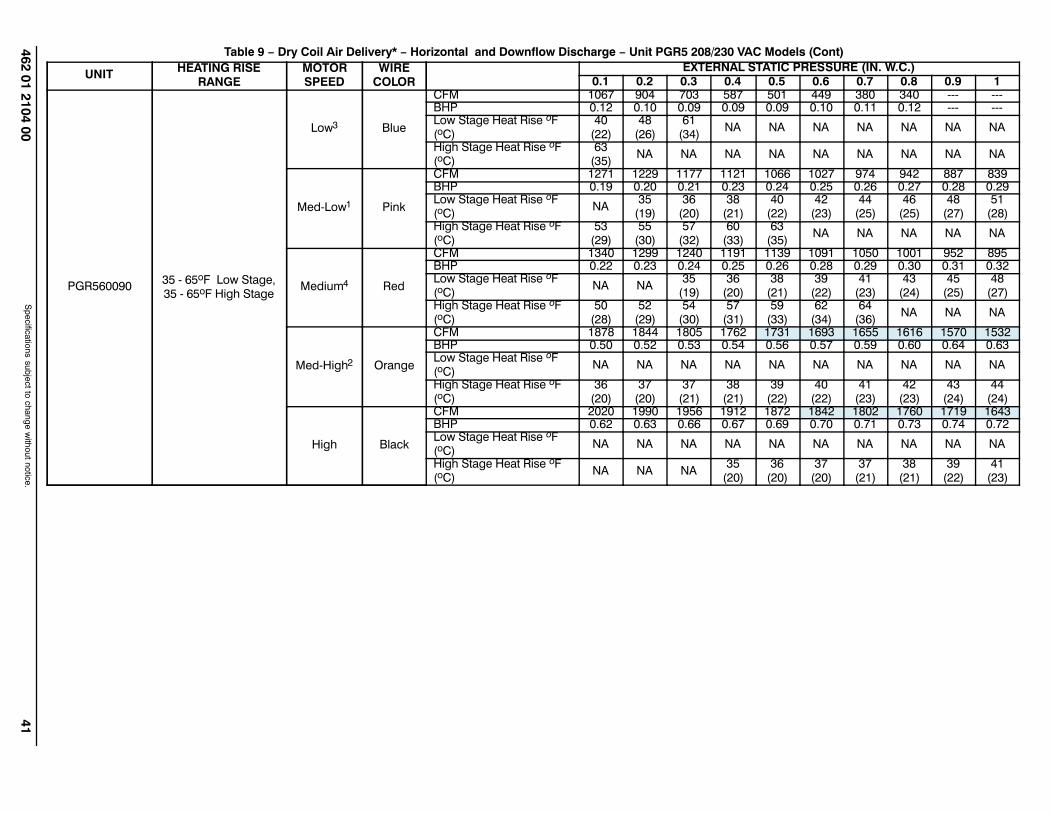
462 01 2104 0041
Specifications subject to change w
ithout notice.
Table 9 − Dry Coil Air Delivery* − Horizontal and Downflow Discharge − Unit PGR5 208/230 VAC Models (Cont)
UNITHEATING RISE
RANGEMOTORSPEED
WIRECOLOR
EXTERNAL STATIC PRESSURE (IN. W.C.)
0.1 0.2 0.3 0.4 0.5 0.6 0.7 0.8 0.9 1
PGR56009035 65oF Low Stage,35 65oF High Stage
Low3 Blue
CFM 1067 904 703 587 501 449 380 340 BHP 0.12 0.10 0.09 0.09 0.09 0.10 0.11 0.12 Low Stage Heat Rise oF(oC)
40(22)
48(26)
61(34)
NA NA NA NA NA NA NA
High Stage Heat Rise oF(oC)
63(35)
NA NA NA NA NA NA NA NA NA
MedLow1 Pink
CFM 1271 1229 1177 1121 1066 1027 974 942 887 839BHP 0.19 0.20 0.21 0.23 0.24 0.25 0.26 0.27 0.28 0.29Low Stage Heat Rise oF(oC)
NA35
(19)36
(20)38
(21)40
(22)42
(23)44
(25)46
(25)48
(27)51
(28)High Stage Heat Rise oF(oC)
53(29)
55(30)
57(32)
60(33)
63(35)
NA NA NA NA NA
Medium4 Red
CFM 1340 1299 1240 1191 1139 1091 1050 1001 952 895BHP 0.22 0.23 0.24 0.25 0.26 0.28 0.29 0.30 0.31 0.32Low Stage Heat Rise oF(oC)
NA NA35
(19)36
(20)38
(21)39
(22)41
(23)43
(24)45
(25)48
(27)High Stage Heat Rise oF(oC)
50(28)
52(29)
54(30)
57(31)
59(33)
62(34)
64(36)
NA NA NA
MedHigh2 Orange
CFM 1878 1844 1805 1762 1731 1693 1655 1616 1570 1532BHP 0.50 0.52 0.53 0.54 0.56 0.57 0.59 0.60 0.64 0.63Low Stage Heat Rise oF(oC)
NA NA NA NA NA NA NA NA NA NA
High Stage Heat Rise oF(oC)
36(20)
37(20)
37(21)
38(21)
39(22)
40(22)
41(23)
42(23)
43(24)
44(24)
High Black
CFM 2020 1990 1956 1912 1872 1842 1802 1760 1719 1643BHP 0.62 0.63 0.66 0.67 0.69 0.70 0.71 0.73 0.74 0.72Low Stage Heat Rise oF(oC)
NA NA NA NA NA NA NA NA NA NA
High Stage Heat Rise oF(oC)
NA NA NA35
(20)36
(20)37
(20)37
(21)38
(21)39
(22)41
(23)

42462 01 2104 00
Specifications subject to change w
ithout notice.
Table 9 − Dry Coil Air Delivery* − Horizontal and Downflow Discharge − Unit PGR5 208/230 VAC Models (Cont)
UNITHEATING RISE
RANGEMOTORSPEED
WIRECOLOR
EXTERNAL STATIC PRESSURE (IN. W.C.)
0.1 0.2 0.3 0.4 0.5 0.6 0.7 0.8 0.9 1
PGR56011530 60oF Low Stage,30 60oF High Stage
Low1 Blue
CFM 1271 1229 1177 1121 1066 1027 974 942 887 839BHP 0.19 0.20 0.21 0.23 0.24 0.25 0.26 0.27 0.28 0.29Low Stage Heat Rise oF(oC)
44(24)
45(25)
47(26)
50(28)
52(29)
54(30)
57(32)
59(33)
NA NA
High Stage Heat Rise oF(oC)
NA NA NA NA NA NA NA NA NA NA
MedLow3 Pink
CFM 1340 1299 1240 1191 1139 1091 1050 1001 952 895BHP 0.22 0.23 0.24 0.25 0.26 0.28 0.29 0.30 0.31 0.32Low Stage Heat Rise oF(oC)
42(23)
43(24)
45(25)
47(26)
49(27)
51(28)
53(30)
56(31)
59(33)
NA
High Stage Heat Rise oF(oC)
NA NA NA NA NA NA NA NA NA NA
Medium Red
CFM 1686 1650 1617 1576 1544 1503 1468 1433 1393 1356BHP 0.42 0.44 0.45 0.46 0.48 0.49 0.51 0.52 0.53 0.55Low Stage Heat Rise oF(oC)
33(18)
34(19)
35(19)
35(20)
36(20)
37(21)
38(21)
39(22)
40(22)
41(23)
High Stage Heat Rise oF(oC)
52(29)
53(29)
54(30)
55(31)
56(31)
58(32)
59(33)
NA NA NA
MedHigh2 Orange
CFM 1878 1844 1805 1762 1731 1693 1655 1616 1570 1532BHP 0.50 0.52 0.53 0.54 0.56 0.57 0.59 0.60 0.64 0.63Low Stage Heat Rise oF(oC)
30(17)
30(17)
31(17)
32(18)
32(18)
33(18)
34(19)
35(19)
36(20)
36(20)
High Stage Heat Rise oF(oC)
46(26)
47(26)
48(27)
49(27)
50(28)
51(29)
53(29)
54(30)
55(31)
57(32)
High4 Black
CFM 1934 1900 1855 1815 1778 1737 1695 1656 1606 1528BHP 0.59 0.61 0.62 0.64 0.65 0.67 0.68 0.70 0.70 0.68Low Stage Heat Rise oF(oC)
NA NA30
(17)31
(17)31
(17)32
(18)33
(18)34
(19)35
(19)37
(20)High Stage Heat Rise oF(oC)
45(25)
46(25)
47(26)
48(27)
49(27)
50(28)
51(28)
52(29)
54(30)
57(32)

462 01 2104 0043
Specifications subject to change w
ithout notice.
Table 9 − Dry Coil Air Delivery* − Horizontal and Downflow Discharge − Unit PGR5 208/230 VAC Models (Cont)
UNITHEATING RISE
RANGEMOTORSPEED
WIRECOLOR
EXTERNAL STATIC PRESSURE (IN. W.C.)
0.1 0.2 0.3 0.4 0.5 0.6 0.7 0.8 0.9 1
PGR56013035 65oF Low Stage,35 65oF High Stage
Low1 Blue
CFM 1271 1229 1177 1121 1066 1027 974 942 887 839BHP 0.19 0.20 0.21 0.23 0.24 0.25 0.26 0.27 0.28 0.29Low Stage Heat Rise oF(oC)
49(27)
51(28)
53(30)
56(31)
59(33)
61(34)
64(36)
NA NA NA
High Stage Heat Rise oF(oC)
NA NA NA NA NA NA NA NA NA NA
MedLow3 Pink
CFM 1340 1299 1240 1191 1139 1091 1050 1001 952 895BHP 0.22 0.23 0.24 0.25 0.26 0.28 0.29 0.30 0.31 0.32Low Stage Heat Rise oF(oC)
47(26)
48(27)
51(28)
53(29)
55(31)
57(32)
60(33)
63(35)
NA NA
High Stage Heat Rise oF(oC)
NA NA NA NA NA NA NA NA NA NA
Medium Red
CFM 1686 1650 1617 1576 1544 1503 1468 1433 1393 1356BHP 0.42 0.44 0.45 0.46 0.48 0.49 0.51 0.52 0.53 0.55Low Stage Heat Rise oF(oC)
37(21)
38(21)
39(22)
40(22)
41(23)
42(23)
43(24)
44(24)
45(25)
46(26)
High Stage Heat Rise oF(oC)
57(32)
58(32)
59(33)
61(34)
62(35)
64(35)
65(36)
NA NA NA
MedHigh2 Orange
CFM 1878 1844 1805 1762 1731 1693 1655 1616 1570 1532BHP 0.50 0.52 0.53 0.54 0.56 0.57 0.59 0.60 0.64 0.63Low Stage Heat Rise oF(oC)
NA NA35
(19)36
(20)36
(20)37
(21)38
(21)39
(22)40
(22)41
(23)High Stage Heat Rise oF(oC)
51(28)
52(29)
53(30)
54(30)
55(31)
57(31)
58(32)
59(33)
61(34)
63(35)
High4 Black
CFM 1934 1900 1855 1815 1778 1737 1695 1656 1606 1528BHP 0.59 0.61 0.62 0.64 0.65 0.67 0.68 0.70 0.70 0.68Low Stage Heat Rise oF(oC)
NA NA NA35
(19)35
(20)36
(20)37
(21)38
(21)39
(22)41
(23)High Stage Heat Rise oF(oC)
50(28)
50(28)
52(29)
53(29)
54(30)
55(31)
57(31)
58(32)
60(33)
63(35)
Notes:1 Factoryshipped low stage cooling speed2 Factoryshipped high stage cooling speed3 Factoryshipped low stage gas heating speed4 Factoryshipped high stage gas heating speed Allowable High Stage Enhanced Dehumidification Cooling Speed"NA" = Not allowed for particular heating speed

44462 01 2104 00
Specifications subject to change w
ithout notice.
Table 10 – Wet Coil Pressure Drop (IN. W.C.)
UNITSIZE
STANDARD CFM (SCFM)
600 700 800 900 1000 1100 1200 1300 1400 1500 1600 1700 1800 1900 2000 2100 2200
24 0.03 0.04 0.04 0.05 0.06
30 0.05 0.06 0.07 0.08 0.11
36 0.06 0.06 0.09 0.10 0.11 0.14
42 0.05 0.05 0.06 0.07 0.08 0.08 0.09 0.09 0.11
48 0.04 0.06 0.09 0.10 0.10 0.11 0.12 0.13 0.14
60 0.06 0.07 0.01 0.08 0.09 0.10 0.12 0.13
Table 11 – Economizer with 1−in. Filter Pressure Drop (IN. W.C.)
FILTER SIZE IN. (MM)COOLING
TONSSTANDARD CFM (SCFM)
600 700 800 900 1000 1100 1200 1300 1400 1500 1600 1700 1800 1900 2000 2100 22006001400 CFM
12x20x1+12x20x1
(305x508x25+305x508x25)
2.0,2.5,3.0
− − 0.09 0.14 0.16 0.18 0.25 0.28 0.30 − − − − − − − −
12001800 CFM
16x24x1+14x24x1
(406x610x25+356x610x25)
3.5,4.0 − − − − − − 0.10 0.11 0.12 0.13 0.14 0.16 0.16 − − − −
15002200 CFM
16x24x1+18x24x1
(406x610x25+457x610x25)
5.0 − − − − − − − − − 0.15 0.17 0.18 0.20 0.21 0.22 0.23 0.23
Table 12 – Filter Pressure Drop Table (IN. W.C.)
FILTER SIZE IN. (MM)COOLING
TONSSTANDARD CFM (SCFM)
600 700 800 900 1000 1100 1200 1300 1400 1500 1600 1700 1800 1900 2000 2100 22006001400 CFM
12x20x1+12x20x1
(305x508x25+305x508x25)
2.0,2.5,3.0
0.03 0.05 0.06 0.08 0.10 0.11 0.13 0.14 0.16 − − − − − − − −
12001800 CFM
16x24x1+14x24x1
(406x610x25+356x610x25)
3.5,4.0 − − − − − − 0.07 0.08 0.09 0.09 0.10 0.11 0.12 − − − −
15002200 CFM
16x24x1+18x24x1
(406x610x25+457x610x25)
5.0 − − − − − − − − − 0.04 0.06 0.08 0.10 0.11 0.13 0.14 0.15

440 01 4300 00 45Specifications subject to change without notice.
MAINTENANCETo ensure continuing high performance and to minimize thepossibility of premature equipment failure, periodicmaintenance must be performed on this equipment. This unitshould be inspected at least once each year by a qualifiedservice person. To troubleshoot unit, refer to Table 13−15,Troubleshooting Chart.NOTE TO EQUIPMENT OWNER: Consult your local dealerabout the availability of a maintenance contract.
PERSONAL INJURY AND UNIT DAMAGE HAZARD
Failure to follow this warning could result in personalinjury or death and unit component damage.
The ability to properly perform maintenance on thisequipment requires certain expertise, mechanicalskills, tools and equipment. If you do not possessthese, do not attempt to perform any maintenance onthis equipment, other than those proceduresrecommended in the Owner’s Manual.
! WARNING
ELECTRICAL SHOCK HAZARD
Failure to follow these warnings could result inpersonal injury or death:1. Turn off electrical power to the unit and install lock
out tag before performing any maintenance orservice on this unit.
2. Use extreme caution when removing panels andparts.
3. Never place anything combustible either on or incontact with the unit.
! WARNING
UNIT OPERATION HAZARD
Failure to follow this caution may result in improperoperation.
Errors made when reconnecting wires may causeimproper and dangerous operation. Label all wiresprior to disconnecting when servicing.
CAUTION!
ENVIRONMENTAL HAZARD
Failure to follow this caution may result inenvironmental pollution.
Remove and re−cycle all components or materials(i.e. oil, refrigerant, etc) before unit final disposal.
! CAUTION
The minimum maintenance requirements for this equipment areas follows:
1. Inspect air filter(s) each month. Clean or replace whennecessary.
2. Inspect indoor coil, drain pan, and condensate draineach cooling season for cleanliness. Clean whennecessary.
3. Inspect blower motor and wheel for cleanliness at thebeginning of each heating and cooling season. Cleanwhen necessary. For first heating and cooling season,inspect blower wheel bi−monthly to determine propercleaning frequency.
4. Check electrical connections for tightness and controlsfor proper operation each heating and cooling season.Service when necessary.
5. Ensure electric wires are not in contact with refrigeranttubing or sharp metal edges.
6. Check and inspect heating section before each heatingseason. Clean and adjust when necessary.
7. Check flue hood and remove any obstructions, ifnecessary.
Air FilterIMPORTANT: Never operate the unit without a suitableair filter in the return−air duct system. Always replacethe filter with the same dimensional size and type asoriginally installed. See Table 1 for recommended filtersizes.Inspect air filter(s) at least once each month and replace(throwaway−type) or clean (cleanable−type) at least twiceduring each cooling season and twice during the heatingseason, or whenever the filter becomes clogged with dust andlint.
Indoor Blower and MotorNOTE: All motors are pre−lubricated. Do not attempt tolubricate these motors.For longer life, operating economy, and continuing efficiency,clean accumulated dirt and grease from the blower wheel andmotor annually.
ELECTRICAL SHOCK HAZARD
Failure to follow this warning could result in personalinjury or death.
Disconnect and tag electrical power to the unit beforecleaning the blower motor and wheel.
! WARNING
To clean the blower motor and wheel:1. Remove and disassemble blower assembly as follows:
a. Remove blower access panel (see Figure 20).b. Disconnect 5 pin plug and 4 pin plug from indoor
blower motor. Remove capacitor if required.c. On all units remove blower assembly from unit.
Remove screws securing blower to blower partitionand slide assembly out. Be careful not to tearinsulation in blower compartment.
d. Ensure proper reassembly by marking blower wheeland motor in relation to blower housing beforedisassembly.
e. Loosen setscrew(s) that secures wheel to motorshaft, remove screws that secure motor mountbrackets to housing, and slide motor and motormount out of housing.
2. Remove and clean blower wheel as follows:a. Ensure proper reassembly by marking wheel
orientation.b. Lift wheel from housing. When handling and/or
cleaning blower wheel, be sure not to disturb balanceweights (clips) on blower wheel vanes.
c. Remove caked−on dirt from wheel and housing witha brush. Remove lint and/or dirt accumulations fromwheel and housing with vacuum cleaner, using soft

46 440 01 4300 00Specifications subject to change without notice.
brush attachment. Remove grease and oil with mildsolvent.
d. Reassemble wheel into housing.e. Reassemble motor into housing. Be sure setscrews
are tightened on motor shaft flats and not on roundpart of shaft. Reinstall blower into unit. Reinstallcapacitor.
f. Connect 5 pin plug and 4 pin plug to indoor blowermotor.
g. Reinstall blower access panel (see Figure 20).3. Restore electrical power to unit. Start unit and check for
proper blower rotation and motor speeds during heatingand cooling cycles.
Induced Draft (combustion air) BlowerAssemblyThe induced−draft blower assembly consists of the inducermotor, the blower housing, and the induced−draft blower wheel.Clean periodically to assure proper airflow and heatingefficiency. Inspect blower wheel every fall and periodicallyduring the heating season. For the first heating season, inspectblower wheel bimonthly to determine proper cleaningfrequency.To inspect blower wheel, remove draft hood assembly. Shine aflashlight into opening to inspect wheel. If cleaning is required,remove induced−draft blower assembly as follows:
1. Remove control access panel (See Figure 20).2. Remove the 5 screws that attach induced−draft blower
assembly to the flue collector box cover.3. Slide the assembly out of the unit. (See Figure 22).
Clean the blower wheel. If additional cleaning is required,continue with Steps 4 and 5.
4. To remove blower wheel, remove 2 setscrews.5. To remove inducer motor, remove screws that hold the
inducer motor to the blower housing.6. To reinstall, reverse the procedure outlined above.
Flue Gas Passageways1To inspect the flue collector box and upper areas of the heatexchanger:
1. Remove the induced draft blower assembly according todirections in the Induced Draft Blower Assembly section.
2. Remove the 11 screws holding the flue collector boxcover (See Figure 19) to the heat exchanger assembly.Inspect the heat exchangers.
3. Clean all surfaces, as required, using a wire brush.
Limit SwitchRemove blower access panel (see Figure 20). Limit switch(es)are located on the fan partition.
Burner IgnitionUnit is equipped with a direct spark ignition 100 percent lockoutsystem. Ignition module (IGC) is located in the control box (SeeFigure 19). Module contains a self−diagnostic LED. Duringservicing, refer to label diagram or Table 5 in these instructionsfor LED interpretation.If lockout occurs, unit may be reset by either momentarilyinterrupting power supply to unit or by turning selector switch toOFF position at the thermostat.
Main BurnersAt the beginning of each heating season, inspect fordeterioration or blockage due to corrosion or other causes.Observe the main burner flames and adjust, if necessary.
Removal of Gas TrainTo remove the gas train for servicing:
1. Shut off main gas valve.2. Shut off power to unit and install lockout tag.3. Remove control access panel (See Figure 20).4. Disconnect gas piping at unit gas valve.5. Remove fan partition mounting bracket (2 screws located
on the left side of control compartment on the fanpartition panel). Slide bracket forward, bottom first, toremove. (See Figure 19.)
6. Remove wires connected to gas valve. Mark each wire.7. Remove the mounting screw that attaches the burner
rack to the unit base (See Figure 19).8. Partially slide the burner rack out of the unit (see
Figure 19 and Figure 22). Remove ignitor and sensorwires at the burner assembly. Remove wires to rolloutswitch.
9. Slide the burner rack out of the unit (See Figure 19 andFigure 22).
10. To reinstall, reverse the procedure outlined above.11. Check all connections for leaks.
FIRE, EXPLOSION HAZARD
Failure to follow this warning could result in personalinjury, death or property damage.
Do not purge gas supply into the combustionchamber. Do not use a match or other open flame tocheck for gas leaks.Use a commercially available soap solution madespecifically for the detection of leaks to check allconnections. A fire or explosion may result causingproperty damage, personal injury or loss of life.
! WARNING
Outdoor Coil, Indoor Coil, and CondensateDrain PanInspect the condenser coil, evaporator coil, and condensatedrain pan at least once each year.The coils are easily cleaned when dry; therefore, inspect andclean the coils either before or after each cooling season.Remove all obstructions, including weeds and shrubs, thatinterfere with the airflow through the condenser coil.Straighten bent fins with a fin comb. If coated with dirt or lint,clean the coils with a vacuum cleaner, using the soft brushattachment. Be careful not to bend the fins. If coated with oil orgrease, clean the coils with a mild detergent and water solution.Rinse coils with clear water, using a garden hose. Be carefulnot to splash water on motors, insulation, wiring, or air filter(s).For best results, spray condenser coil fins from inside tooutside the unit. On units with an outer and inner condensercoil, be sure to clean between the coils. Be sure to flush all dirtand debris from the unit base.Inspect the drain pan and condensate drain line wheninspecting the coils. Clean the drain pan and condensate drainby removing all foreign matter from the pan. Flush the pan anddrain trough with clear water. Do not splash water on theinsulation, motor, wiring, or air filter(s). If the drain trough isrestricted, clear it with a “plumbers snake” or similar probedevice.

440 01 4300 00 47Specifications subject to change without notice.
Integrated Gas UnitController(IGC)
Induced DraftMotor
RolloutSwitchMounting
ScrewBurnerRack
InducerBlowerHousing
FlueCollector Box
Interface FanBoard (IFB)
Fan PartitionMountingBracket
L13P006
Figure 19 − Blower Housing and Flue Collector Box
CompressorAccess Panel
ControlAccessPanelBlower
AccessPanel
A09211
Figure 20 − Unit Access Panels
BLOWERHOUSING
2 SETSCREWS(HIDDEN)
C99085
Figure 21 − Removal of Motor and Blower Wheel
A07680
Figure 22 − Burner Rack Removed
Outdoor Fan
UNIT OPERATION HAZARD
Failure to follow this caution may result in damage tounit components.
Keep the condenser fan free from all obstructions toensure proper cooling operation. Never place articleson top of the unit.
CAUTION!
1. Remove 6 screws holding outdoor grille and motor to topcover.
2. Turn motor/grille assembly upside down on top cover toexpose fan blade.
3. Inspect the fan blades for cracks or bends.4. If fan needs to be removed, loosen setscrew and slide
fan off motor shaft.5. When replacing fan blade, position blade as shown in
Figure 23.6. Ensure that setscrew engages the flat area on the motor
shaft when tightening.7. Replace grille.
Electrical Controls and WiringInspect and check the electrical controls and wiring annually.Be sure to turn off the electrical power to the unit.Remove access panels (see Figure 20) to locate all theelectrical controls and wiring. Check all electrical connectionsfor tightness. Tighten all screw connections. If any smoky orburned connections are noticed, disassemble the connection,clean all the parts, re−strip the wire end and reassemble theconnection properly and securely.After inspecting the electrical controls and wiring, replace all thepanels. Start the unit, and observe at least one completecooling cycle to ensure proper operation. If discrepancies areobserved in operating cycle, or if a suspected malfunction hasoccurred, check each electrical component with the properelectrical instrumentation. Refer to the unit wiring label whenmaking these checks.

48 440 01 4300 00Specifications subject to change without notice.
MOTOR FAN GRILLE
MOTOR SHAFT
A
A08505
MAX DISTANCE BETWEEN TOP OF FAN GRILLE AND BOTTOM OF FAN BLADE
SIZE“A”
IN. MM24 6.3 16030 6.3 16036 7.6 19342 7.6 19348 7.6 19360 7.6 193
Figure 23 − Fan Blade Position
Refrigerant Circuit Annually inspect all refrigerant tubing connections and the unitbase for oil accumulations. Detecting oil generally indicates arefrigerant leak.
EXPLOSION, SAFETY AND ENVIRONMENTALHAZARD
Failure to follow this warning could result in personalinjury, death or property damage.
System under pressure. Relieve pressure andrecover all refrigerant before system repair or final unitdisposal. Use all service ports and open allflow−control devices, including solenoid valves.
! WARNING
If oil is detected or if low cooling performance is suspected,leak−test all refrigerant tubing using an electronicleak−detector, halide torch, or liquid−soap solution. If arefrigerant leak is detected, refer to the Check for RefrigerantLeaks section.If no refrigerant leaks are found and low cooling performance issuspected, refer to the Checking and Adjusting RefrigerantCharge section.
Gas Input The gas input does not require checking unless improperheating performance is suspected. If a problem exists, refer tothe Start−Up section.
Evaporator AirflowThe heating and/or cooling airflow does not require checkingunless improper performance is suspected. If a problem exists,be sure that all supply− and return−air grilles are open and freefrom obstructions, and that the air filter is clean. Whennecessary, refer to the Indoor Airflow and Airflow Adjustmentssection to check the system airflow.
R−410A ItemsMetering Device (Thermostatic ExpansionValve )This metering device is a hard shutoff, balance port TXV. TheTXV maintains a constant superheat at the evaporator exitresulting in higher overall system efficiency.
Pressure SwitchesPressure switches are protective devices wired into controlcircuit (low voltage). They shut off compressor if abnormallyhigh or low pressures are present in the refrigeration circuit.These pressure switches are specifically designed to operatewith R−410A systems. R−22 pressure switches must not beused as replacements for the R−410A system.
Loss of Charge SwitchThis switch is located on the liquid line and protects against lowsuction pressures caused by such events as loss of charge,low airflow across indoor coil, dirty filters, etc. It opens on apressure drop at about 20 psig. If system pressure is abovethis, switch should be closed. To check switch:
1. Turn off all power to unit.2. Disconnect leads on switch.3. Apply ohm meter leads across switch. You should have
continuity on a good switch.NOTE: Because these switches are attached to refrigerationsystem under pressure, it is not advisable to remove this devicefor troubleshooting unless you are reasonably certain that aproblem exists. If switch must be removed, remove and recoverall system charge so that pressure gauges read 0 psig. Neveropen system without breaking vacuum with dry nitrogen.
High−Pressure SwitchThe high−pressure switch is located in the discharge line andprotects against excessive condenser coil pressure. It opens at650 psig.High pressure may be caused by a dirty outdoor coil, failed fanmotor, or outdoor air recirculation. To check switch:

440 01 4300 00 49Specifications subject to change without notice.
1. Turn off all power to unit.2. Disconnect leads on switch.3. Apply ohm meter leads across switch. You should have
continuity on a good switch.
Copeland Scroll Compressor (R−410ARefrigerant)The compressor used in this product is specifically designed tooperate with R−410A refrigerant and cannot be interchanged.The compressor is an electrical (as well as mechanical) device.Exercise extreme caution when working near compressors.Power should be shut off, if possible, for most troubleshootingtechniques. Refrigerants present additional safety hazards.
FIRE/EXPLOSION HAZARD
Failure to follow this warning could result in personalinjury or death and/or property damage.
Wear safety glasses and gloves when handlingrefrigerants. Keep torches and other ignition sourcesaway from refrigerants and oils.
! WARNING
The scroll compressor pumps refrigerant throughout the systemby the interaction of a stationary and an orbiting scroll. Thescroll compressor has no dynamic suction or discharge valves,and it is more tolerant of stresses caused by debris, liquidslugging, and flooded starts. The compressor is equipped witha noise reducing shutdown device and an internal pressurerelief port. The pressure relief port is a safety device, designedto protect against extreme high pressure. The relief port has anoperating range between 550 (26.34 kPa) and 625 psig (29.93kPa) differential pressure.
EXPLOSION, ENVIRONMENTAL SAFETY HAZARD
Failure to follow this warning could result in personalinjury, death or equipment damage.
This system uses R−410A refrigerant which hashigher operating pressures than R−22 and otherrefrigerants. No other refrigerant may be used in thissystem. Gauge set, hoses, and recovery systemmust be designed to handle R−410A. If you areunsure, consult the equipment manufacturer.
WARNING!
Refrigerant SystemThis information covers the refrigerant system of the PGR5,including the compressor oil needed, servicing systems onroofs containing synthetic materials, the filter drier andrefrigerant charging.Compressor OilThe Copeland scroll compressor uses 3MAF POE oil. Ifadditional oil is needed, use Uniqema RL32−3MAF. If this oil isnot available, use Copeland Ultra 32 CC or Mobil Arctic EAL22CC. This oil is extremely hygroscopic, meaning it absorbs waterreadily. POE oils can absorb 15 times as much water as otheroils designed for HCFC and CFC refrigerants. Take allnecessary precautions to avoid exposure of the oil to theatmosphere.
Servicing Systems on Roofs with SyntheticMaterialsPOE (polyolester) compressor lubricants are known to causelong term damage to some synthetic roofing materials.Exposure, even if immediately cleaned up, may causeembrittlement (leading to cracking) to occur in one year ormore. When performing any service that may risk exposure ofcompressor oil to the roof, take appropriate precautions toprotect roofing. Procedures which risk oil leakage include, butare not limited to, compressor replacement, repairing refrigerantleaks, replacing refrigerant components such as filter drier,pressure switch, metering device, coil, accumulator, orreversing valve.
Synthetic Roof Precautionary Procedure1. Cover extended roof working area with an impermeable
polyethylene (plastic) drip cloth or tarp. Cover anapproximate 10 X 10 ft. (3.1 m X 3.1 m) area.
2. Cover area in front of the unit service panel with a terrycloth shop towel to absorb lubricant spills and preventrun−offs, and protect drop cloth from tears caused bytools or components.
3. Place terry cloth shop towel inside unit immediatelyunder component(s) to be serviced and prevent lubricantrun−offs through the louvered openings in the unit base.
4. Perform required service.5. Remove and dispose of any oil contaminated material
per local codes.
Liquid Line Filter DrierThis filter drier is specifically designed to operate with R−410A.Use only factory−authorized components. Filter drier must bereplaced whenever the refrigerant system is opened. Whenremoving a filter drier, use a tubing cutter to cut the drier fromthe system. Do not unsweat a filter drier from the system. Heatfrom unsweating will release moisture and contaminants fromdrier into system.
R−410A Refrigerant ChargingRefer to unit information plate and charging chart. SomeR−410A refrigerant cylinders contain a dip tube to allow liquidrefrigerant to flow from cylinder in upright position. For cylindersequipped with a dip tube, charge R−410A units with cylinder inupright position and a commercial metering device in manifoldhose. Charge refrigerant into suction−line.
TROUBLESHOOTINGUse the Troubleshooting Guides (See Tables 13−15) ifproblems occur with these units.
START−UP CHECKLIST Use Start−Up checklist to ensure proper start−up proceduresare followed.

50 440 01 4300 00Specifications subject to change without notice.
R−410A QUICK REFERENCE GUIDE
� R−410A refrigerant operates at 50−70 percent higher pressures than R−22. Be sure that servicingequipment and replacement components are designed to operate with R−410A
� R−410A refrigerant cylinders are rose colored.
� Recovery cylinder service pressure rating must be 400 psig, DOT 4BA400 or DOT BW400.
� R−410A systems should be charged with liquid refrigerant. Use a commercial type metering device in the
manifold hose when charging into suction line with compressor operating
� Manifold sets should be minimum 700 psig high side and 180 psig low side with 550 psig low−side
retard.
� Use hoses with minimum 700 psig service pressure rating.
� Leak detectors should be designed to detect HFC refrigerant.
� R−410A, as with other HFCs, is only compatible with POE oils.
� Vacuum pumps will not remove moisture from oil.
� Do not use liquid−line filter driers with rated working pressures less than 600 psig.
� Do not leave R−410A suction line filter driers in line longer than 72 hrs.
� Do not install a suction−line filter drier in liquid line.
� POE oils absorb moisture rapidly. Do not expose oil to atmosphere.
� POE oils may cause damage to certain plastics and roofing materials.
� Wrap all filter driers and service valves with wet cloth when brazing.
� A factory approved liquid−line filter drier is required on every unit.
� Do NOT use an R−22 TXV.
� Never open system to atmosphere while it is under a vacuum.
� When system must be opened for service, recover refrigerant, evacuate then break vacuum with dry
nitrogen and replace filter driers. Evacuate to 500 microns prior to recharging.
� Do not vent R−410A into the atmosphere.
� Observe all warnings, cautions, and bold text.
� All indoor coils must be installed with a hard shutoff R−410A TXV metering device.

440 01 4300 00 51Specifications subject to change without notice.
Table 13 – Troubleshooting ChartSYMPTOM CAUSE REMEDY
Compressor and condenser fan will not start.
Power failure Call power company
Fuse blown or circuit breaker tripped Replace fuse or reset circuit breaker
Defective contactor, transformer, or high−pressure,loss−of−charge or low−pressure switch
Replace component
Insufficient line voltage Determine cause and correct
Incorrect or faulty wiring Check wiring diagram and rewire correctly
Thermostat setting too highLower thermostat temperature setting below roomtemperature
Compressor will not start but condenser fanruns
Faulty wiring or loose connections in compressor cir-cuit Check wiring and repair or replace
Compressor motor burned out, seized, or Determine cause
internal overload open Replace compressor
Defective run/start capacitor, overload, start relay Determine cause and replace
One leg of 3−phase power deadReplace fuse or reset circuit breakerDetermine cause
Low input voltage Determine cause and correct
Three−phase scroll compressor
Scroll compressor is rotating in the wrong direction
Correct the direction of rotation by reversing the
makes excessive noise, and there may be a lowpressure differential.
3−phase power leads to the unit. Shut down unit toallow pressures to equalize.
Compressor cycles (other than normally satis-fying thermostat)
Refrigerant overcharge or underchargeRecover refrigerant, evacuate system, and rechargeto capacities shown on rating plate
Defective compressor Replace and determine cause
Insufficient line voltage Determine cause and correct
Blocked outdoor coil Determine cause and correct
Defective run/start capacitor Determine cause and replace
Faulty outdoor fan motor or capacitor Replace
Restriction in refrigerant system Locate restriction and remove
Compressor operates continuously
Dirty air filter Replace filter
Unit undersized for load Decrease load or increase unit size
Thermostat temperature set too low Reset thermostat
Low refrigerant charge Locate leak, repair, and recharge
Air in system Recover refrigerant, evacuate system, and recharge
Outdoor coil dirty or restricted Clean coil or remove restriction
Excessive head pressure
Dirty air filter Replace filter
Dirty condenser coil Clean coil
Refrigerant overcharged Recover excess refrigerant
Air in system Recover refrigerant, evacuate system, and recharge
Condenser air restricted or air short−cycling Determine cause and correct
Head pressure too lowLow refrigerant charge Check for leaks, repair, and recharge.
Restriction in liquid tube Remove restriction
Excessive suction pressure Refrigerant overcharged Recover excess refrigerant
Suction pressure too low
Dirty air filter Replace filter
Low refrigerant charge Check for leaks, repair and recharge
Metering device or low side restricted Remove source of restriction
Insufficient evaporator airflowIncrease air quantityCheck filter–replace if necessary
Temperature too low in conditioned area Reset thermostat
Outdoor ambient below 55°F (13°C) Install low−ambient kit
Filter drier restricted Replace filter

52 440 01 4300 00Specifications subject to change without notice.
Table 14 – Troubleshooting Guide–HeatingSYMPTOM CAUSE REMEDY
Burners will not ignite
Water in gas line Drain. Install drip leg.
No power to furnace Check power supply fuses, wiring or circuit breaker.
No 24−v power supply to control circuitCheck transformer.NOTE: Some transformers have internal over−current protectionthat requires a cool−down period to reset.
Mis−wired or loose connections Check all wiring and wire nut connections
Misaligned spark electrodesCheck flame ignition and sense electrode positioning.Adjust as necessary.
No gas at main burners
1. Check gas line for air. Purge as necessary. NOTE: After purginggas line of air, wait at least 5 minutes for any gas to dissipate beforeattempting to light unit.2. Check gas valve.
Inadequate heating
Dirty air filter Clean or replace filter as necessary
Gas input to furnace too low Check gas pressure at manifold match with that on unit nameplate
Unit undersized for application Replace with proper unit or add additional unit
Restricted airflow Clean or replace filter. Remove any restriction.
Limit switch cycles main burnersCheck rotation of blower, temperature rise of unit. Adjust as neces-sary.
Poor flame characteristics Incomplete combustion results in: Aldehyde odors, carbonmonoxide, sooting flame, floating flame
1. Tighten all screws around burner compartment2. Cracked heat exchanger. Replace.3. Unit over−fired. Reduce input (change orifices or adjust gas lineor manifold pressure).4. Check burner alignment.5. Inspect heat exchanger for blockage. Clean as necessary.
Table 15 – Troubleshooting Guide–LED Status CodesSYMPTOM CAUSE REMEDY
No Power or Hardware failure(LED OFF) Loss of power to control module (IGC)*.
Check 5−amp fuse son IGC*, power to unit, 24−v circuit breaker,and transformer. Units without a 24−v circuit breaker have aninternal overload in the 24−v transformer. If the overload trips, allow10 minutes for automatic reset.
Limit switch faults(LED 2 flashes) High temperature limit switch is open.
Check the operation of the indoor (evaporator) fan motor. Ensurethat the supply−air temperature rise is in accordance with the rangeon the unit nameplate. Clean or replace filters.
Flame sense fault(LED 3 flashes) The IGC* sensed flame that should not be present. Reset unit. If problem persists, replace control board.
4 consecutive limit switch faults(LED 4 flashes) Inadequate airflow to unit.
Check the operation of the indoor (evaporator) fan motor and thatsupply−air temperature rise agrees with range on unit nameplateinformation.
Ignition lockout fault(LED 5 flashes) Unit unsuccessfully attempted ignition for 15 minutes.
Check ignitor and flame sensor electrode spacing, gaps, etc.Ensure that fame sense and ignition wires are properly terminated.Verify that unit is obtaining proper amount of gas.
Pressure Switch fault(LED 6 flashes) Open pressure switch.
Verify wiring connections to pressure switch and inducer motor.Verify pressure switch hose is tightly connected to both inducerhousing and pressure switch. Verify inducer wheel is properlyattached to inducer motor shaft. Verify inducer motor shaft isturning.
Rollout switch fault(LED 7 flashes) Rollout switch has opened.
Rollout switch will automatically reset, but IGC* will continue tolockout unit. Check gas valve operation. Ensure that induced−draftblower wheel is properly secured to motor shaft. Inspect heatexchanger. Reset unit at unit disconnect.
Internal control fault(LED 8 flashes)
Microprocessor has sensed an error in the software orhardware.
If error code is not cleared by resetting unit power, replace theIGC*.
Temporary 1 hr auto reset1(LED 9 flashes) Electrical interference impeding IGC software
Reset 24−v. to control board or turn thermostat off, then on again.Fault will automatically reset itself in one (1) hour.
*WARNING : If the IGC must be replaced, be sure to ground yourself to dissipate any electrical charge that my be present before handling new control board. TheIGC is sensitive to static electricity and my be damaged if the necessary precautions are not taken.IMPORTANT: Refer to Table 14−Troubleshooting Guide−Heating for additional troubleshooting analysis.LEGENDIGC—Integrated Gas Unit ControllerLED—Light−Emitting Diode

440 01 4300 00 53Specifications subject to change without notice.
START−UP CHECKLIST(Remove and Store in Job Files)
I. PRELIMINARY INFORMATIONMODEL NO.:SERIAL NO.:DATE:TECHNICIAN:
II. PRESTART−UP (Insert check mark in box as each item is completed)( ) VERIFY THAT ALL PACKING MATERIALS HAVE BEEN REMOVED FROM UNIT( ) REMOVE ALL SHIPPING HOLD DOWN BOLTS AND BRACKETS PER INSTALLATION INSTRUCTIONS( ) CHECK ALL ELECTRICAL CONNECTIONS AND TERMINALS FOR TIGHTNESS( ) CHECK GAS PIPING FOR LEAKS (WHERE APPLICABLE)( ) CHECK THAT INDOOR (EVAPORATOR) AIR FILTER IS CLEAN AND IN PLACE( ) VERIFY THAT UNIT INSTALLATION IS LEVEL( ) CHECK FAN WHEEL, AND PROPELLER FOR LOCATION IN HOUSING/ORIFICE AND SETSCREW TIGHTNESS
III. START−UPELECTRICALSUPPLY VOLTAGECOMPRESSOR AMPSINDOOR (EVAPORATOR) FAN AMPSTEMPERATURESOUTDOOR (CONDENSER) AIR TEMPERATURE DBRETURN−AIR TEMPERATURE DB WBCOOLING SUPPLY AIR DB WBGAS HEAT SUPPLY AIRPRESSURESGAS INLET PRESSURE IN. W.C.GAS MANIFOLD PRESSURE (HIGH STAGE) IN. W.C.GAS MANIFOLD PRESSURE (LOW STAGE) IN. W.C.REFRIGERANT SUCTION PSIG, SUCTION LINE TEMP*REFRIGERANT DISCHARGE PSIG, LIQUID TEMP�( ) VERIFY REFRIGERANT CHARGE USING CHARGING CHARTSHIGH STAGE GAS HEAT TEMPERATURE RISERANGE (See Literature)MEASURED TEMPERATURE RISE (HIGH STAGE)LOW STAGE GAS HEAT TEMPERATURE RISE RANGE (208/230 VAC MODELS)MEASURED LOW STAGE TEMPERATURE RISE RANGE (208/230 VAC MODELS) * Measured at suction inlet to compressor� Measured at liquid line leaving condenser.
International Comfort Products � PO Box 128 �Lewisburg, TN 37091 USA


![PACKAGEHEATPUMPSFEATURING INDUSTRYSTANDARDR-410A … · 2020. 3. 17. · []indicatesmetricconversion installationinstructions packageheatpumpsfeaturing industrystandardr-410a refrigerant](https://img.dokumen.tips/doc/110x75/5ff73ec723717515a65c591b/packageheatpumpsfeaturing-industrystandardr-410a-2020-3-17-indicatesmetricconversion.jpg)