Embed Size (px)
Citation preview
15461 SLOVER AVE., FONTANA, CA 92337 | PH: 909.947.0015, FAX: 909.947.0603 | WWW.SBFILTERS.COM
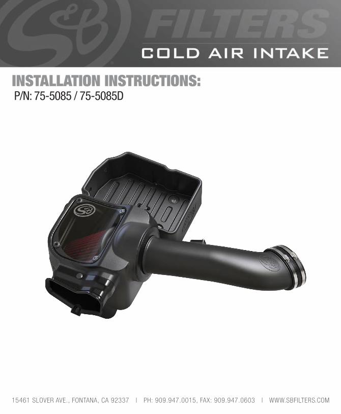
P/N: 75-5085 / 75-5085DINSTALLATION INSTRUCTIONS:
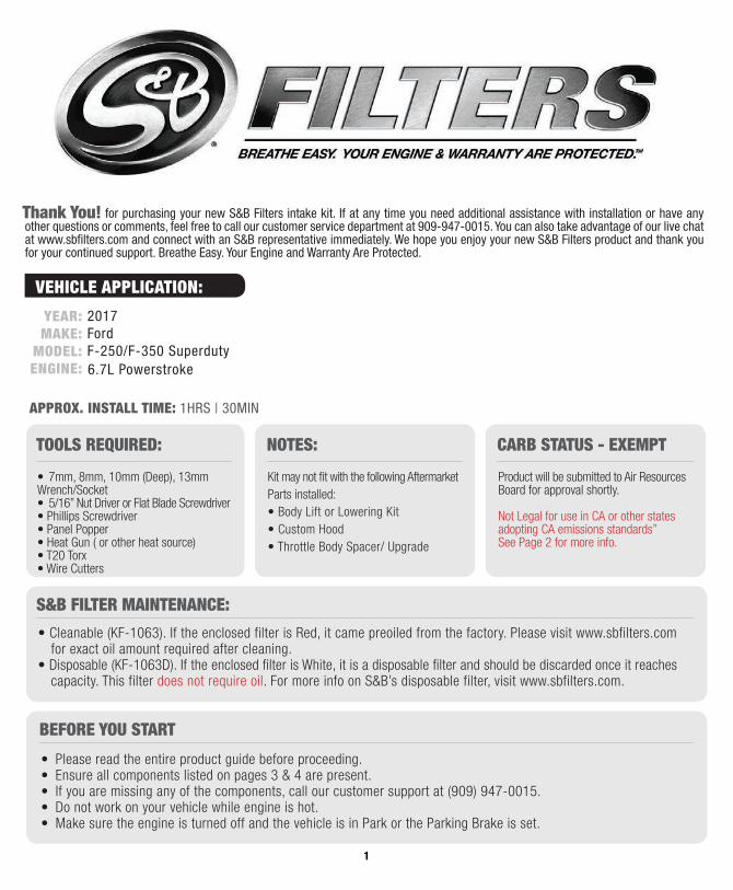
• 7mm, 8mm, 10mm (Deep), 13mm Wrench/Socket• 5/16” Nut Driver or Flat Blade Screwdriver• Phillips Screwdriver• Panel Popper• Heat Gun ( or other heat source)• T20 Torx• Wire Cutters
TOOLS REQUIRED:
• Cleanable (KF-1063). If the enclosed filter is Red, it came preoiled from the factory. Please visit www.sbfilters.com for exact oil amount required after cleaning.• Disposable (KF-1063D). If the enclosed filter is White, it is a disposable filter and should be discarded once it reaches capacity. This filter does not require oil. For more info on S&B’s disposable filter, visit www.sbfilters.com.
S&B FILTER MAINTENANCE:
• Please read the entire product guide before proceeding.• Ensure all components listed on pages 3 & 4 are present.• If you are missing any of the components, call our customer support at (909) 947-0015.• Do not work on your vehicle while engine is hot.• Make sure the engine is turned off and the vehicle is in Park or the Parking Brake is set.
BEFORE YOU START
Kit may not fit with the following Aftermarket Parts installed:• Body Lift or Lowering Kit• Custom Hood• Throttle Body Spacer/ Upgrade
NOTES:
Product will be submitted to Air ResourcesBoard for approval shortly.
Not Legal for use in CA or other states adopting CA emissions standards”See Page 2 for more info.
CARB STATUS - EXEMPT
for purchasing your new S&B Filters intake kit. If at any time you need additional assistance with installation or have any other questions or comments, feel free to call our customer service department at 909-947-0015. You can also take advantage of our live chat at www.sbfilters.com and connect with an S&B representative immediately. We hope you enjoy your new S&B Filters product and thank you for your continued support. Breathe Easy. Your Engine and Warranty Are Protected.
Thank You!
2017FordF-250/F-350 Superduty6.7L Powerstroke
APPROX. INSTALL TIME: 1HRS | 30MIN
YEAR: MAKE:
MODEL: ENGINE:
1
VEHICLE APPLICATION:

SBFILTERS.COM
Stock intake boxes are a significant contributor to poor air flow which is why S&B designs custom air boxes with secondary and/or enlarged openings. With that said, S&B recognizes the benefits of cooler air, so we have included a plug to seal off the opening if so desired. For optimal performance, we recommend that the intake be used without the end cap except in conditions of extreme heat.
Intake Box Plug Testing
The California Air Resource Board (CARB) requires that an E.O. Identification label be applied to the vehicle in order to pass a smog check inspection when a Performance Intake Kit has been installed. You must place the E.O. Label provided on or near the intake kit after installation so that a smog check technician can easily verify the E.O. Number. The exemption process with CARB can take as long as 18 months. Check the status of the exemption process by looking up a specific part number at www.sbfilters.com. The CARB Exemption number and/or status is listed under the Product Details section for each part number. If the status shows as “Pending,” CARB has yet to issue an exemption but the product has been submitted. Products that have not been issued an E.O. number are street legal in most states, but may not be used on emission controlled vehicles in the state of California and are for off road use only. If you purchased your kit from S&B Filters directly, we will automatically mail you your Exemption Sticker when it is issued to us. If you purchased your kit from an authorized S&B Filters Dealer, log onto our web site and register to receive your Exemption Sticker.
Emissions Standard
If your vehicle has a Vehicle Emission Control Information decal affixed to the factory air box, a new replacement label must be obtained and installed in a readily visible position in the engine compartment in order to remain CARB compliant. Failure to do so will prevent the vehicle from passing a smog check. Replacement labels can be ordered from your local dealership. Regulations state that the VECI label shall not be affixed to any equipment which is easily detached from the vehicle. Label placement, under the hood on a painted surface is recommended.
Warning!
• After your installation is complete engage parking brake and start your engine. Listen for abnormal noises. If an air leak is detected, re-inspect hoses and connections as they may need to be repositioned and tightened.• S&B Filters recommends that you keep your OE intake system in the event it is required in the future.• In order to maintain your warranty, all connections and components must be checked periodically for alignment and for proper tension on all connections. Failure to do so may void your warranty.• Use only S&B Filters cleaning and oil products to service your filter. Using any other brand oil and/or cleaners on your S&B air filter may void your warranty.
Performance Testing
Order Online today at www.sbfilters.com or through your local S&B distributor.
ReplacementCotton FilterSKU# KF-1063
Replacement Dry Filter
SKU# KF-1063D
Precision II: Cleaning & Oil Kit
SKU# 88-0008
2
RELATED ITEMS FOR YOUR PURCHASE
3
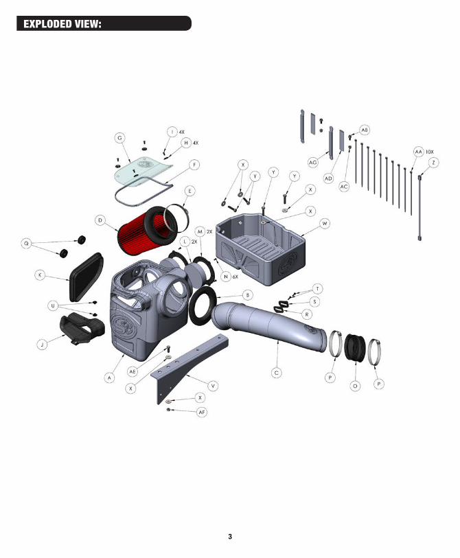
EXPLODED VIEW:
SBFILTERS.COM4
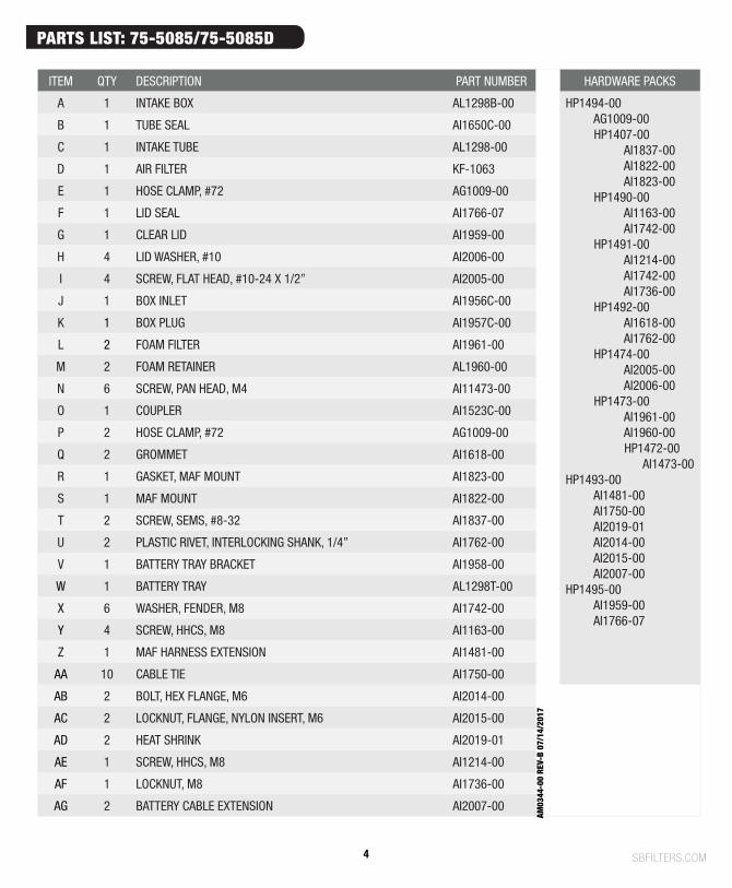
ITEM QTY DESCRIPTION PART NUMBER HARDWARE PACKS
A 1 INTAKE BOX AL1298B-00 HP1494-00 AG1009-00 HP1407-00 AI1837-00 AI1822-00 AI1823-00 HP1490-00 AI1163-00 AI1742-00 HP1491-00 AI1214-00 AI1742-00 AI1736-00 HP1492-00 AI1618-00 AI1762-00 HP1474-00 AI2005-00 AI2006-00 HP1473-00 AI1961-00 AI1960-00 HP1472-00 AI1473-00HP1493-00 AI1481-00 AI1750-00 AI2019-01 AI2014-00 AI2015-00 AI2007-00HP1495-00 AI1959-00 AI1766-07
B 1 TUBE SEAL AI1650C-00
C 1 INTAKE TUBE AL1298-00
D 1 AIR FILTER KF-1063
E 1 HOSE CLAMP, #72 AG1009-00
F 1 LID SEAL AI1766-07
G 1 CLEAR LID AI1959-00
H 4 LID WASHER, #10 AI2006-00
I 4 SCREW, FLAT HEAD, #10-24 X 1/2” AI2005-00
J 1 BOX INLET AI1956C-00
K 1 BOX PLUG AI1957C-00
L 2 FOAM FILTER AI1961-00
M 2 FOAM RETAINER AL1960-00
N 6 SCREW, PAN HEAD, M4 AI11473-00
O 1 COUPLER AI1523C-00
P 2 HOSE CLAMP, #72 AG1009-00
Q 2 GROMMET AI1618-00
R 1 GASKET, MAF MOUNT AI1823-00
S 1 MAF MOUNT AI1822-00
T 2 SCREW, SEMS, #8-32 AI1837-00
U 2 PLASTIC RIVET, INTERLOCKING SHANK, 1/4” AI1762-00
V 1 BATTERY TRAY BRACKET AI1958-00
W 1 BATTERY TRAY AL1298T-00
X 6 WASHER, FENDER, M8 AI1742-00
Y 4 SCREW, HHCS, M8 AI1163-00
Z 1 MAF HARNESS EXTENSION AI1481-00
AA 10 CABLE TIE AI1750-00
AB 2 BOLT, HEX FLANGE, M6 AI2014-00
AC 2 LOCKNUT, FLANGE, NYLON INSERT, M6 AI2015-00
AD 2 HEAT SHRINK AI2019-01
AE 1 SCREW, HHCS, M8 AI1214-00
AF 1 LOCKNUT, M8 AI1736-00
AG 2 BATTERY CABLE EXTENSION AI2007-00
PARTS LIST: 75-5085/75-5085D
AM03
44-0
0 RE
V-B
07/1
4/20
17
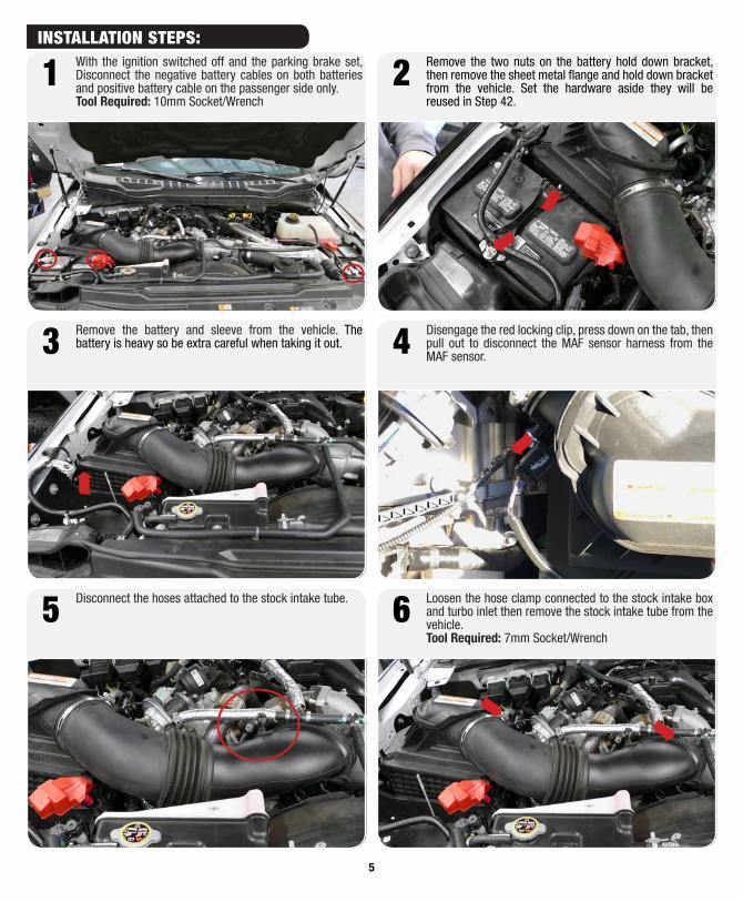
With the ignition switched off and the parking brake set, Disconnect the negative battery cables on both batteries and positive battery cable on the passenger side only.Tool Required: 10mm Socket/Wrench
1 Remove the two nuts on the battery hold down bracket, then remove the sheet metal flange and hold down bracket from the vehicle. Set the hardware aside they will be reused in Step 42.
2
Remove the battery and sleeve from the vehicle. The battery is heavy so be extra careful when taking it out.3 Disengage the red locking clip, press down on the tab, then
pull out to disconnect the MAF sensor harness from the MAF sensor. 4
Disconnect the hoses attached to the stock intake tube.5 Loosen the hose clamp connected to the stock intake box and turbo inlet then remove the stock intake tube from the vehicle.Tool Required: 7mm Socket/Wrench
6
5
INSTALLATION STEPS:
SBFILTERS.COM
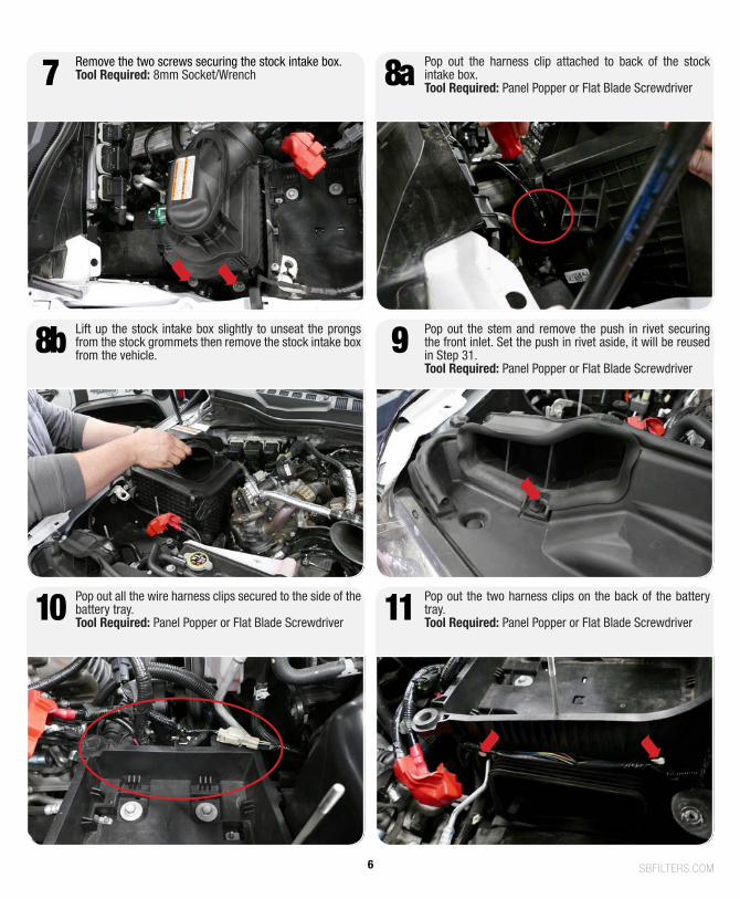
Remove the two screws securing the stock intake box.Tool Required: 8mm Socket/Wrench7
Lift up the stock intake box slightly to unseat the prongs from the stock grommets then remove the stock intake box from the vehicle. 8b Pop out the stem and remove the push in rivet securing
the front inlet. Set the push in rivet aside, it will be reused in Step 31.Tool Required: Panel Popper or Flat Blade Screwdriver
9
Pop out all the wire harness clips secured to the side of the battery tray.Tool Required: Panel Popper or Flat Blade Screwdriver10 Pop out the two harness clips on the back of the battery
tray.Tool Required: Panel Popper or Flat Blade Screwdriver11
Pop out the harness clip attached to back of the stock intake box.Tool Required: Panel Popper or Flat Blade Screwdriver8a
6
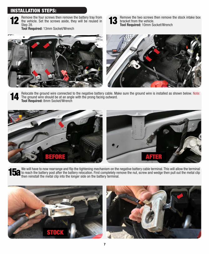
Remove the four screws then remove the battery tray from the vehicle. Set the screws aside, they will be reused in Step 28.Tool Required: 13mm Socket/Wrench
12
We will have to now rearrange and flip the tightening mechanism on the negative battery cable terminal. This will allow the terminal to reach the battery post after the battery relocation. First completely remove the nut, screw and wedge then pull out the metal clip then reinstall the metal clip into the longer side on the battery terminal.15a
Relocate the ground wire connected to the negative battery cable. Make sure the ground wire is installed as shown below. Note: The ground wire should be at an angle with the prong facing outward.Tool Required: 8mm Socket/Wrench14
Remove the two screws then remove the stock intake box bracket from the vehicle.Tool Required: 10mm Socket/Wrench13
BEFORE AFTER
STOCK
7
INSTALLATION STEPS:
SBFILTERS.COM
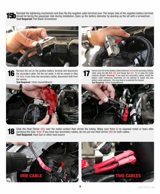
Reinstall the tightening mechanism and then flip the negative cable terminal over. The longer side of the negative battery terminal should be facing the passenger side during installation. Open up the battery diameter by opening up the slit with a screwdriver.Tool Required: Flat Blade Screwdriver15b
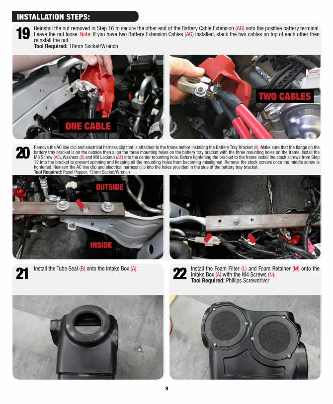
16 Remove the nut on the positive battery terminal and disconnect the secondary cable. Set the nut aside, it will be reused in Step 19. Note: If you have two secondary cables, disconnect both from the vehicle. Tool Required: 10mm Socket/Wrench
18 Slide the Heat Shrink (AD) over the metal contact then shrink the tubing. Make sure there is no exposed metal or tears after shrinking the tube. Note: If you have two secondary cables, do not use one Heat Shrink (AD) for both cables. Tool Required: Heat Gun or other heat source
17 Secure one end of the Battery Cable Extension (AG) to the secondary battery cable using the M6 Bolt (AB) and Flange Nut (AC). Try to keep the metal contacts straight. Warning!: If you have two secondary cables, install the battery cable extensions separately. Do not attempt to install only one battery cable extension. This may lead to a potential fire hazard.Tool Required: 10mm Socket/Wrench
ONE CABLE TWO CABLES
8
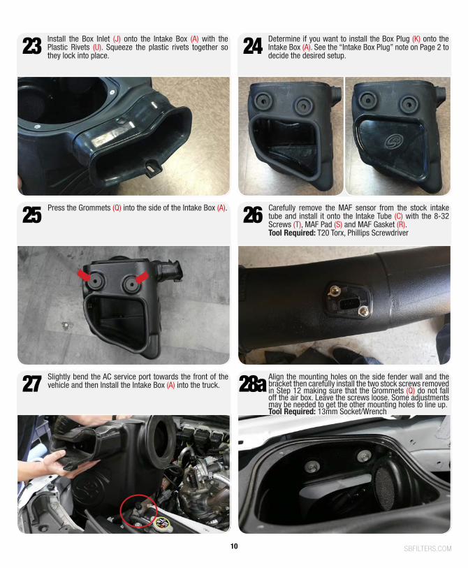
Remove the AC line clip and electrical harness clip that is attached to the frame before installing the Battery Tray Bracket (V). Make sure that the flange on the battery tray bracket is on the outside then align the three mounting holes on the battery tray bracket with the three mounting holes on the frame. Install the M8 Screw (AE), Washers (X) and M8 Locknut (AF) into the center mounting hole. Before tightening the bracket to the frame install the stock screws from Step 12 into the bracket to prevent spinning and keeping all the mounting holes from becoming misaligned. Remove the stock screws once the middle screw is tightened. Reinsert the AC line clip and electrical harness clip into the holes provided in the side of the battery tray bracket.Tool Required: Panel Popper, 13mm Socket/Wrench
20
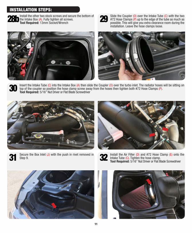
Install the Tube Seal (B) onto the Intake Box (A).21 Install the Foam Filter (L) and Foam Retainer (M) onto the Intake Box (A) with the M4 Screws (N).Tool Required: Phillips Screwdriver22
19 Reinstall the nut removed in Step 16 to secure the other end of the Battery Cable Extension (AG) onto the positive battery terminal. Leave the nut loose. Note: If you have two Battery Extension Cables (AG) installed, stack the two cables on top of each other then reinstall the nut. Tool Required: 10mm Socket/Wrench
OUTSIDE
INSIDE
ONE CABLE
TWO CABLES
9
INSTALLATION STEPS:
SBFILTERS.COM
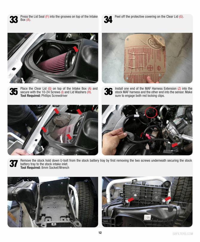
Install the Box Inlet (J) onto the Intake Box (A) with the Plastic Rivets (U). Squeeze the plastic rivets together so they lock into place.23 Determine if you want to install the Box Plug (K) onto the
Intake Box (A). See the “Intake Box Plug” note on Page 2 to decide the desired setup. 24
Press the Grommets (Q) into the side of the Intake Box (A).25
Slightly bend the AC service port towards the front of the vehicle and then Install the Intake Box (A) into the truck.27 Align the mounting holes on the side fender wall and the
bracket then carefully install the two stock screws removed in Step 12 making sure that the Grommets (Q) do not fall off the air box. Leave the screws loose. Some adjustments may be needed to get the other mounting holes to line up.Tool Required: 13mm Socket/Wrench
28a
Carefully remove the MAF sensor from the stock intake tube and install it onto the Intake Tube (C) with the 8-32 Screws (T), MAF Pad (S) and MAF Gasket (R).Tool Required: T20 Torx, Phillips Screwdriver
26
10
28b Install the other two stock screws and secure the bottom of the Intake Box (A). Fully tighten all screws. Tool Required: 13mm Socket/Wrench 29 Slide the Coupler (O) over the Intake Tube (C) with the two
#72 Hose Clamps (P) up to the edge of the tube as much as possible. This will give you extra clearance room during the installation. Leave the hose clamps loose.
Insert the Intake Tube (C) into the Intake Box (A) then slide the Coupler (O) over the turbo inlet. The radiator hoses will be sitting on top of the coupler so position the hose clamp screw away from the hoses then tighten both #72 Hose Clamps (P).Tool Required: 5/16” Nut Driver or Flat Blade Screwdriver30
32 Install the Air Filter (D) and #72 Hose Clamp (E) onto the Intake Tube (C). Tighten the hose clamp.Tool Required: 5/16” Nut Driver or Flat Blade Screwdriver31 Secure the Box Inlet (J) with the push in rivet removed in
Step 9.
11
INSTALLATION STEPS:
SBFILTERS.COM
37
35 Place the Clear Lid (G) on top of the Intake Box (A) and secure with the 10-24 Screws (I) and Lid Washers (H).Tool Required: Phillips Screwdriver
Remove the stock hold down U-bolt from the stock battery tray by first removing the two screws underneath securing the stock battery tray to the stock intake inlet.Tool Required: 8mm Socket/Wrench
36 Install one end of the MAF Harness Extension (Z) into the stock MAF harness and the other end into the sensor. Make sure to engage both red locking clips.
34 Peel off the protective covering on the Clear Lid (G).33 Press the Lid Seal (F) into the grooves on top of the Intake Box (A).
12
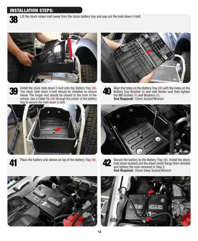
38 Lift the stock intake inlet away from the stock battery tray and pop out the hold down U-bolt.
41 Place the battery and sleeve on top of the Battery Tray (W). Secure the battery to the Battery Tray (W). Install the stock hold down bracket and the sheet metal flange then reinstall and tighten the nuts removed in Step 2.Tool Required: 10mm Deep Socket/Wrench
42
39 Install the stock hold down U-bolt onto the Battery Tray (W). The stock hold down U-bolt should be installed as shown below. The longer end should be closest to the front of the vehicle. Use a Cable Tie (AA) through the center of the battery tray to secure the hold down U-bolt.
Align the holes on the Battery Tray (W) with the holes on the Battery Tray Bracket (V) and side fender wall then tighten the M8 Screws (Y) and Washers (X). Tool Required: 13mm Socket/Wrench
40
13
INSTALLATION STEPS:
SBFILTERS.COM
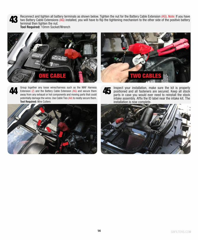
44 Group together any loose wires/harness such as the MAF Harness Extension (Z) and the Battery Cable Extension (AG) and secure them away from any exhaust or hot components and moving parts that could potentially damage the wires. Use Cable Ties (AA) to neatly secure them.Tool Required: Wire Cutters
43
Inspect your installation, make sure the kit is properly positioned and all fasteners are secured. Keep all stock parts in case you would ever need to reinstall the stock intake assembly. Affix the ID label near the intake kit. The installation is now complete.
Reconnect and tighten all battery terminals as shown below. Tighten the nut for the Battery Cable Extension (AG). Note: If you have two Battery Cable Extensions (AG) installed, you will have to flip the tightening mechanism to the other side of the positive battery terminal then tighten the nut.Tool Required: 10mm Socket/Wrench
45
ONE CABLE TWO CABLES
14

15461 SLOVER AVE., FONTANA, CA 92337 | PH: 909.947.0015, FAX: 909.947.0603 | WWW.SBFILTERS.COM