Embed Size (px)
Citation preview

ALTO CONTRACT IDEALFORMACRYLIC BATHS
Installation InstructionsPlease pass on to user
4762 07/10 EE72534367
4762 Alto Acrylic Baths:Alto CT Baths 27/07/2010 05:22 Page 1

ALTO CONTRACT IDEALFORM ACRYLIC BATH
180
tap holes 37 dia
X
X
A
C maxC min
100 100bracket bracketleg adjuster
Fig. 2 centres of leg adjusters
Fig. 1
All dimensions shown in millimetres.Dimensions shown may vary within permitted tolerances.
B
ED
Section X - X
TECHNICAL INFORMATION
A B C Max C Min D E Water capacityto overflow
ltrs
Alto CT WS 1695 695 540 500 370 495 140
Alto CT WS 1695 695 540 500 370 495 149
Alto CT 1695 695 540 500 370 495 175
4762 Alto Acrylic Baths:Alto CT Baths 27/07/2010 05:22 Page 2
Alto CT 1495 695 540 500 370 495 149

ALTO CONTRACT IDEALFORM ACRYLIC BATH
Ref.
A
C
B
D
E
F
G
H
J
K
L
Description
Bath Tub
Centre Support Leg
Bath Legs
Short Bath Foot
Bath Feet
Plastic Leg Adjuster
Bath Feet Locking Nuts
No. 8 x 12 Pan Head Self Tapping Screw
No. 8 x 16 Countersunk Woodscrew
No. 8 x 20 Pan Head Self Tapping Screw
No. 8 x 30 Countersunk Woodscrew
Wall Bracket
Qty.
1
1
2
1
4
4
10
4
2
10
4
2M
W
W
V
X
Cushioning Strip
Cushioning Strip
Panel
Panel
Front Panel
End Panel
3
2
1
1
Fig. 3
4762 Alto Acrylic Baths:Alto CT Baths 27/07/2010 05:22 Page 3

ALTO CONTRACT IDEALFORM ACRYLIC BATH
BATH CONDITIONBefore commencing installation, carefully remove packaging/protective film and check for dam-
age. If damaged, report immediately to supplier.
The bath should be fully protected during the installation process.
Fig. 1 illustrates baths fitted with rigid panels
INSTALLATION
1. Lay bath face down and remove legs and bags containing feet etc.
2. Locate leg adjusters on bath frame and mark positions for the fixing screws. Note: If fitting wooden panels, locate outside face of leg adjuster flush with outside face of frame. Pilot drill Ø2mm holes in the bath frame and fix leg adjusters to frame.
3. Locate bath legs in leg adjusters and mark positions for the fixing screws on the base board. Pilot drill Ø2mm holes in the base board, to a depth of 6mmmaximum. Position legs in leg adjusters and on base board and secure. LocateNo. 8 x 12 long pan head self tapping screw into leg adjuster and tighten.
DO NOT OVER TIGHTEN
4. Locate centre support bracket, mark screw hole positions, pilot drill Ø2mm holes inbase board, to a depth of 6mm maximum, and secure bracket.
5. Fix the feet and adjust to give approximate floor to top of rim height required.Trial fit the panel(s) to verify height is correct. Note: Untrimmed panel fitment requires the maximum height adjustment (Cmax Fig1). Remember to allow for flooring thicknesses.
6. Fit supply and waste fittings. If the bath is to be installed with a monoblock mixer a special hole (or holes) is required to accommodate the mixer and will have to be cut by the installer in an appropriate position on the rim of a no tap holebath to suit the bathroom layout. Full details or a template for cutting the hole (orholes) is supplied with monoblock fittings. A template for cutting two tap holes ina no tap hole bath is supplied with the bath. Cut tap holes, and fit supply fittings,waste, overflow and trap. When using a monoblock fitting, the area directly be-hind the pop-up waste mechanism should be avoided.
The 4 black - No. 8 x 40 long countersunk crosshead self tapping screws retaining the legs are NOT REQUIRED and should be discarded.
Appropriate safety equipment/workwear should be used
4762 Alto Acrylic Baths:Alto CT Baths 27/07/2010 05:22 Page 4
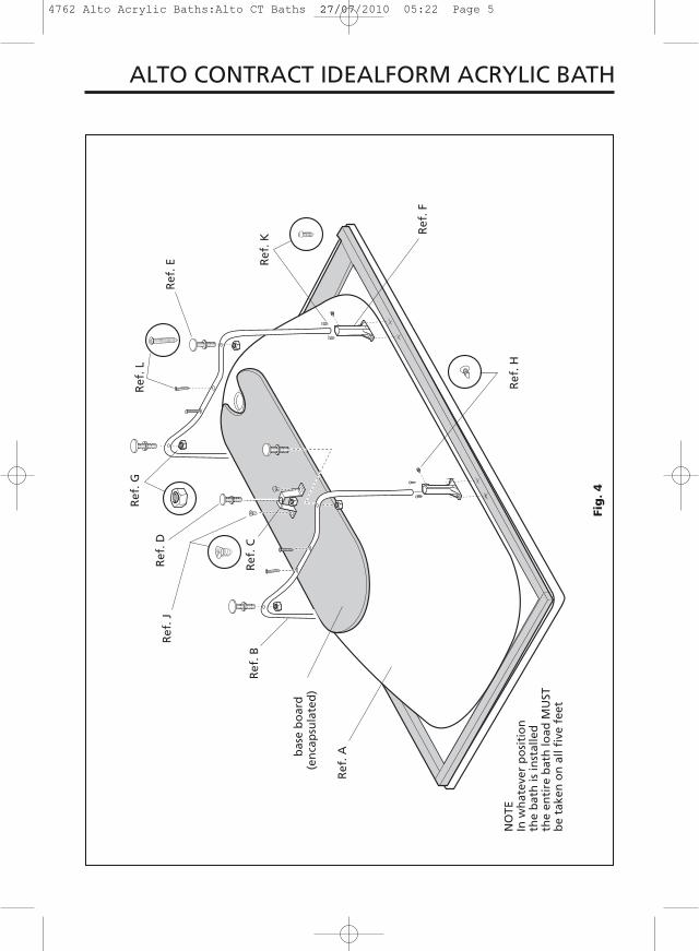
ALTO CONTRACT IDEALFORM ACRYLIC BATH
NO
TEIn
wh
atev
er p
osi
tio
nth
e b
ath
is in
stal
led
the
enti
re b
ath
load
MU
STb
e ta
ken
on
all
five
fee
t
bas
e b
oar
d
Ref
. H
Ref
. F
Ref
. K
Ref
. L
Ref
. E
Ref
. G
Ref
. DR
ef. J
Ref
. CR
ef. B
Ref
. A
Fig
. 4
4762 Alto Acrylic Baths:Alto CT Baths 27/07/2010 05:22 Page 5
(en
cap
sula
ted
)

ALTO CONTRACT IDEALFORM ACRYLIC BATH
8. Fix the two wall fixing brackets to bath frame as indicated in Fig. 6. Pilot drill Ø2mm holes in frame before fixing brackets.
9. Fix bath to wall (Fig. 6)
10. Fix bath to floor and ensure that all nuts are tight.
11. Connect services, test for satisfactory operation of fittings and ensure there are no leaks.
12. Tile down to the height of the bath rim leaving a 3-4mm gap for waterproofsealant, see Fig. 6. An extruded sealing strip can be used for the bath to walljoint as an alternative to waterproof sealant. Protect bath during tiling.
Ref. K(for position of
wall bracket see Fig. 1)
bath frame
waterproofsealant(not supplied)
wall screw(not supplied)
Ref. M
tile
bath
3-4mm gapfor sealant
Fig. 6
Fig. 5
hand gripcarrier
hand grip
grub screw
bath
plastic washer
taper, plastic or rubber washer(as supplied)M8 steel washer
M8 nut
WARNINGDO NOT fix hand grips
in any oil based bedding compound
or putty. These materials contain
solvents which will damage the hand grips irreparably.
7. Fix handgrips wheresupplied.
4762 Alto Acrylic Baths:Alto CT Baths 27/07/2010 05:22 Page 6

PANELS13. Fit panel(s)
Attach the lengths of PVC cushioning strip to the top edge(s) of the panel(s)(three on the front panel and two on the end). Fit panel(s) (end panel first where appropriate) by pushing the top edgeunder the bath rim, Fig. 7.
14. Panels can be reduced in height by cutting a strip from the bottom edge, for heights see Fig. 1. Reducing the panel height requires great care and responsibility cannot be accepted for any errors made. Timber floor battens are not supplied but are necessary to secure the panels.Screw battens to the floor.
ALTO CONTRACT IDEALFORM ACRYLIC BATH
WOODEN PANELS15. Wooden panels can be supported on battens or blocks attached to the bath
frame. Battens are also required for the base of panels and should bescrewed to the floor.
Screw wooden panels to battens and blocks and cover screw heads withscrew caps (not supplied). Installation details for fixing wooden panels to thebath are supplied with the panels.
bath frame bath panel
floor batten(not supplied)
15
No. 8 x 20 longcountersunkwoodscrew andscrew cover cap(not supplied)
bath rim
Ref. X
Ref. W
Ref. VFig. 7
4762 Alto Acrylic Baths:Alto CT Baths 27/07/2010 05:22 Page 7
We pursue a policy of continuing improvement in designand performance of our products. The right is, therefore,reserved to vary specifications without notice.
Ideal Standard (UK) Ltd.
The Bathroom Works National Avenue Kingston upon Hull HU5 4HS England Telephone: (01482) 346461 Telefax: (01482) 445886.
CUSTOMER CARE HELPLINE0870 1296085
CUSTOMER CARE FAX LINE 01482 499611email: [email protected]
ALTO CONTRACT IDEALFORM ACRYLIC BATH
4762 Alto Acrylic Baths:Alto CT Baths 27/07/2010 05:22 Page 8

Close Coupled WCAssembly andInstallation Instructions
4859 Sandringham CC WC Instruction:Cistern fittings 30/01/2012 11:36 Page 1

4859 Sandringham CC WC Instruction:Cistern fittings 30/01/2012 11:36 Page 2

4859 Sandringham CC WC Instruction:Cistern fittings 30/01/2012 11:36 Page 3

Tools Required (not supplied)
● Adjustable Spanner● Screwdriver● Sharp Knife● Pencil or Marker Pen● Power Drill and suitable bit(s)
Parts Required (not supplied)
● Brass Screws and Fixing Plugsto secure the cistern to the wall
● Brass Screws and Fixing Plugsto secure the pan to the floor
Before You Start
● Check the pack and make sure you have all the parts listed. If not, contact the vendor who will be able to help you.
● When you are ready to start, make sure that you have the right toolsto hand, plenty of space and a clean area for assembly.
Important Notes
● The flow restrictor (T) should be used if the inlet water pressure to the inlet valve exceeds 1.4 Bar.
● Take care to avoid cross-threading. Do not overtighten backnuts.
● Caution: Care should always be taken when drilling into walls and floors to avoid any sunken wires or pipes.
● Please Note: Although these instructions are comprehensive, it is alwaysrecommended that a technically competent installer should undertakeinstallation.
● Servicing valve: The Water Regulations have a requirement to fit a servicingvalve adjacent to the cistern. (Not supplied).
4859 Sandringham CC WC Instruction:Cistern fittings 30/01/2012 11:36 Page 4

Assembly
1 Remove the backnut (E) from the inletvalve (D).Insert the inlet valve through the hole in the base of the cistern, ensuring thewasher (F) is in place to seal and cen-tralise the valve in the hole. Secure theinlet valve in position with the backnut,making sure the inlet valve is not in contact with the cistern wall.
2. Remove the backnut (B) from the flushvalve (A). Insert the flush valve throughthe hole in the base of the cistern, ensur-ing that the washer (C) is in place.Place the coupling plate (G) over the tailof the flush valve.Secure the flush valve using backnut,making sure that the flush valve is not incontact with the inlet valve.
3. Place the sealing gasket (donut washer)(K) into the recess on the backplate of theWC pan.Place the two coupling plate bolts (H) intothe slots on either side of the couplingplate (G).Lower the cistern onto the backplate ofthe WC pan.Secure the cistern in position by applyingwashers (I) and wing nuts (J) onto thebolts (H). Do not overtighten.
4859 Sandringham CC WC Instruction:Cistern fittings 30/01/2012 11:36 Page 5

Assembly
4 Place the WC in the required position.With cistern lid removed, mark the position of the screw holes in the rear ofthe cistern and in the base of the pan.Remove the WC away from its locationand drill and plug the positions markedon the wall and floor.Replace the WC in position and secure tothe wall and floor using suitable fixings(not supplied).
5. Connect the water supply and waste connections.Turn on the water supply and allow thecistern to fill.Adjust the float on the inlet valve so thatthe valve stops the flow of water when thewater level is at the same height as thewaterline marked in the cistern.Check for leaks.
4859 Sandringham CC WC Instruction:Cistern fittings 30/01/2012 11:36 Page 6

Fit Push Button
6. Fit the push button (L) into the cistern lidand secure with the washer (M) and backnut (N), aligning the ratchet bar slotsleft and right
7. Push ratchet bars (O) through the pushbutton slots with the spigot ends facingdownwards and outwards, so that thebars project approximately 10mm fromthe cover bush bosses.Push the small button plunger marked ‘A’(part P), onto the right hand ratchet bar.Push the large button plunger marked ‘B’(part Q) onto the left hand ratchet bar.
8. Lower the cistern lid onto the cistern.whilst holding the left hand button firmlydown, push the top end of the ratchet barwith a thin screwdriver down until it stops,then release.
9. Repeat above step for the right hand button.
10, If the top ends of the ratchet bars arelevel or below the push button face, pushthe cover caps, (R & S), onto the corre-sponding buttons, ensuring they snapinto place.
4859 Sandringham CC WC Instruction:Cistern fittings 30/01/2012 11:36 Page 7

Care and Use
● Clean using warm soapy water only.
● Do not use scourers, abrasives or chemical cleaners.
11. If the ratchet bars protrude above thepush button face, make a mark on theratchet bars, level with the button faces.
12. Remove the cistern lid and pull the ratchet bars out of the button from underneath, them remove plungers ‘A’and ‘B’.
13. Cut the ratchet bars on the first notchbelow the mark.
14. Push ratchet bars (O) through the pushbutton slots with the spigot ends facingdownwards and outwards, until the top ofthe ratchet bars are level or just below thepush button face.Push the small button plunger marked ‘A’(part P) onto the right hand ratchet bar.Push the large button plunger marked ‘B’(part Q) onto the left hand ratchet bar.Push the cover caps (R and S) onto the corresponding buttons, ensuring theysnap into place.
15. Lower the cistern lid onto the cistern.
4859 Sandringham CC WC Instruction:Cistern fittings 30/01/2012 11:36 Page 8

Product Care
All our products are designed, manufactured and supplied to give many years of reliable service, provided they are properly maintained and cared for. These are our recommendations to make sure that your bathroom stayslooking good:
Vitreous China – Ceramic toilets, cistern tanks
Do’s
Use warm soapy water, cream or liquid cleaner.
Occasional use of mild bathroom lime scale removers is acceptable.
Use in accordance with manufacturers instructions, rinsing well with plentyof water.
Inlet valve filter to be cleaned regularly.
Don’t
Do not put bleach products in the cistern – this can damage the internal fittings.
It is acceptable to use in the toilet bowl itself.
Never put strong cleaner or bleach in overnight.
Never mix different cleaners in the WC – they can react to give off poisonous gas.
Plastic WC Seats
Do’s
Clean immediately after use to stop a build up of dirt and scale.
Use warm soapy water, Cif cream cleaner or Domestos Multi Active surfacecleaner.
Polish out minor scratches and abrasions with a mild polishing compound.
Don’t
Never leave pools of soap, shampoo or cleaning detergent (please seeabove) – these can cause permanent stains.
Never let cigarettes/flames near - your seat can burn and melt.
Never use household chemicals – a range of products such as paint stripper, nail varnish remover, household bleach, perfume, aftershaveor strong disinfectant.
We cannot recommend the use of any scouring products or cream cleaners other than Cif.
Never mix different cleaners on your seat – they can react to give off poisonous gas.
4859 Sandringham CC WC Instruction:Cistern fittings 30/01/2012 11:36 Page 9

Product Guarantee
L I F E T I M EAll Ideal Standard ceramic products
5 Y E A R SToilet seat and cover
WC cistern fittings
This covers products in domestic use by the consumer and not commercial or business use.
All Ideal Standard products must be installed, used and cared for in linewith our fixing instructions, local water byelaws and
current water regulations.
Access to our products for installation, service or repair and costs relatingto this is the owners or installers’ responsibility.
Parts are guaranteed for five years and will be replaced if found faulty.
This guarantee does not cover general wear and tear.
Applies to the UK and Republic of Ireland only.
4859 Sandringham CC WC Instruction:Cistern fittings 30/01/2012 11:36 Page 10

4859 Sandringham CC WC Instruction:Cistern fittings 30/01/2012 11:36 Page 11
We pursue a policy of continuing improvement in design and performance of our products. The right is,
therefore, reserved to vary specifications without notice.
CUSTOMER CARE HELPLINE0870 1258905
FAX LINE 01482 499611email: [email protected]
4859 01/12
4859 Sandringham CC WC Instruction:Cistern fittings 30/01/2012 11:36 Page 12

!
Ensure that the plastic sleeves, that lock the seat and cover together, are present, Figure 1, before inserting the hinge pins into the sleeves.
Check the orientation of the hinges, Wall Hung pans throw backwards, Figure 2a, Close Coupled and Back to Wall pans throw forwards, Figure 2b. This ensures that the seat lines up correctly.
Fit rubber centralising washers into the holes in the pan and lower the seat and cover, Figure 3, ensuring that the hinges are inserted in the holes in the centralising washers.
Firstly fit a plastic coated washer, then a steel spring washer and nut to the thread of each hinge, Figure 4, before tightening with the tool provided.
Figure 1
Figure 2a
Figure 2b
Figure 3
Figure 4
Sleeve
Sleeve
Hinge Pin

Toilet Seat InstallationAlto and Halo ClosetsImportant Care andInstallation Instructions, Please retain for future reference.
GIN28XX Revision No: 05
CARE AND CLEANING INSTRUCTIONS
- The seat and cover should be cleaned using warm soapy water.
- Do not use aggressive or abrasive cleaners as this may scratch the surface of the seat.
- The hinges should be cleaned using soap, or a mild detergent. After cleaning the hinges should be rinsed in clean water and dried.
- Never use bleach, concentrated cleaners or acids on the hinges as this will cause discolouring and pitting.
- Do not leave bleach in the toilet bowl with the cover closed because this may cause discolouration of the seat and hinges.
- Take care not to splash the hinges when using bleach in the toilet bowl.
Ideal Standard (UK) Ltd. pursues a policy of continuingimprovement in design and performance of its products.The right is, therefore, reserved to vary specificationswithout notice.
The Bathroom Works National Avenue Kingston upon Hull HU5 4HS England Telephone: (01482) 346461 Telefax: (01482) 445886.
CCUUSSTTOOMM EERR CCAARREE HHEELLPPLLIINNEE
FFAAXX LLIINNEE 0011448822 449999661111
4453 05/08
0870 [email protected]