Embed Size (px)
Citation preview

Installation Instructions for
Rayburn 200SFW and Rayburn
212SFW Solid Fuel Cooker
PERFORMANCE
1 02/15 EINS 514406
Consumer Protection
As responsible manufacturers we take care to make sure that our
products are designed and constructed to meet the required safety
standard when properly installed and used.
IMPORTANT NOTICE: PLEASE READ THE ACCOMPANYING
WARRANTY. Any alteration that is not approved by AGA could
invalidate the approval of the appliance, operation of the warranty
and could affect your statutory rights.
All local regulations including those referring to National and
European standards need to be complied with when installing
the appliance.
Important
This appliance may contain some of the materials that are
indicated. It is the Users/Installers responsibility to ensure that the
necessary personal protective clothing is worn when handling,
where applicable, the pertinent parts that contain any of the listed
materials that could be interpreted as being injurious to health and
safety, see below for information.
Firebricks, Fuel beds, Artificial Fuels - when handling use
disposable gloves.
Fire Cement - when handling use disposable gloves.
Glues and Sealants - exercise caution - if these are still in liquid
form use face mask and disposable gloves.
Glass Yarn, Mineral Wool, Insulation Pads, Kerosene/Gas Oil -
may be harmful if inhaled, may be irritating to skin, eyes, nose and
throat. When handling avoid inhaling and contact with skin or
eyes. Use disposable gloves, face-masks and eye protection.
After handling wash hands and other exposed parts. When
disposing of the product, reduce dust with water spray, ensure that
parts are securely wrapped.
WARNING
THE ASHPIT DOOR AND FIREBOX DOORS MUST
BE LOCKED CLOSED AT ALL TIMES DURING
NORMAL USE, EXCEPT WHEN LIGHTING OR RE-
FUELLING
REMEMBER, when replacing a part on this
appliance, use only spare parts that you can be
assured conform to the safety and performance
specification that we require. Do not use
reconditioned or copy parts that have not been
authorised by AGA.
The Rayburn 200SFW is intended to be used for
cooking only. The Rayburn 212SFW is intended to
supply heating for cooking and domestic hot water.
The Rayburn 200SFW has been tested using Ancit and
wood logs. The nominal heat output of this appliance is
Ancit 7.1 kW and wood logs 5.8 kW.
The Rayburn 212SFW has been tested using Ancit and
wood logs. The nominal heat output of this appliance is
Ancit 6.8 kW and wood logs 6.5 kW.
Ancit provides about 2.6 kW to hot water and 4.3 kW to
the appliance. Wood provides about 2.0 kW to hot
water and 4.5 kW to the appliance. Other fuels may
give a slightly different result.
Weight of Rayburn 212SFW - 300 Kgs.
Weight of Rayburn 200SFW - 240 Kgs.
There is no requirement for an electrical power supply.
Flue gas mass flow g/s 5.3.
The mean flue gas temperature of the Rayburn
200SFW directly downstream of the flue spigot at
nominal heat output is 200ºC.
The mean flue gas temperature of the Rayburn
212SFW directly downstream of the flue spigot at
nominal heat output is 203ºC.
The cooker fully meets the requirements of BS EN
12815 : 2001 and A1: 2004 and is fully approved by the
HETAS Ltd Approval Scheme.
Air for combustion within the firebox and the rate of
burning is determined by the manually operated
spinwheel control on the ashpit door and flue damper.
With normal usage in 24 hours continuous burning the
Rayburn 212SFW has an approximate output of 100
gallons of hot water. To provide 2 or 3 hot baths at
intervals and normal household requirements, the
following conditions must be fulfilled:-
FUEL
ANCIT
WOOD
ANCIT
WOOD
FLUE GAS MASS FLOW
MODEL
200
200
212
212
5.3 g/s
5.6 g/s
5.9 g/s
5.9 g/s
MEAN FLUE
GAS TEMP.
199°C
196°C
203°C
207°C
The installation of any electrical services during the
installation of this boiler and the associated heating
system must be carried out by a registered competent
electrician and in accordance with the requirements of
the latest issue of BS 7671.
Rayburn 212SFW - It is recommended that a 140 litre
(30 galls) indirect hot water storage cylinder of the
double feed type, (e.g. manufactured by Albion
Cylinders) complying with BS 1566 Part 1 : DF Type 8
should be lagged and fixed vertically as near as
possible to the cooker.
The maximum water pressure is 1.75 bar.
The water capacity of the boiler is 7 litres.
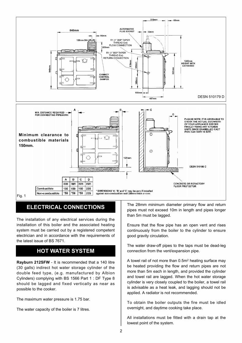
DESN 510179 D
Fig. 1
Minimum clearance to
combustible materials
150mm.
ELECTRICAL CONNECTIONS
HOT WATER SYSTEM
The 28mm minimum diameter primary flow and return
pipes must not exceed 10m in length and pipes longer
than 5m must be lagged.
Ensure that the flow pipe has an open vent and rises
continuously from the boiler to the cylinder to ensure
good gravity circulation.
The water draw-off pipes to the taps must be dead-leg
connection from the vent/expansion pipe.
A towel rail of not more than 0.5m2 heating surface may
be heated providing the flow and return pipes are not
more than 5m each in length, and provided the cylinder
and towel rail are lagged. When the hot water storage
cylinder is very closely coupled to the boiler, a towel rail
is advisable as a heat leak, and lagging should not be
applied. A radiator is not recommended.
To obtain the boiler outputs the fire must be idled
overnight, and daytime cooking take place.
All installations must be fitted with a drain tap at the
lowest point of the system.
2
PREPARATION OF SITE
COOKER POSITION
AIR SUPPLY
3
THE BOILER
Rayburn 212SFW - Unscrew the sheet metal cover
plate on the side of the cooker and remove the
insulating material from behind it.
Joint the flow and return connections to the boiler,
replace the insulating material and screw on the cover
plate and collar.
The boiler is now ready for connection to the hot water
cylinder.
IMPORTANT: LIFT OUT THE HOTPLATE AND
CEMENT SEAL THE JOINT BETWEEN THE BOILER
FACE AND IT LOCATING FACE ON THE FIREBOX
SIDES WITH FIRE CEMENT. RENEW ANY
BRICKWORK CEMENTED JOINTS THAT MAY HAVE
OPENED IN TRANSIT.
The non-combustible hearth must be solid and level
and together with the walls adjacent to the cooker and
chimney, conform to current Building Regulations.
The cooker and chimney flue installation should be in
accordance with the relevant recommendations of
BS8303, BS. EN 15287-1:2007.
Rayburn 212SFW - The boiler installation section must
also be in accordance with the byelaws of the local
Water Undertaking and any relevant requirements of
the Local Authority.
When the cooker is installed in a recess it must be
‘freestanding’ and not built-in solid at the sides.
Where the cooker is to stand in a recess or against
a wall which is to be tiled, in no circumstances
should the tiles overlap the cooker top plate.
Ensure that any combustible material e.g. kitchen
furniture is spaced away from the cooker to the
recommended distances. See Fig. 1. The work surface
however, may be fitted to the top plate on both sides.
NOTE: SMOKE/SMELL EMITTED DURING INITIAL
USAGE
Some parts of the cooker have been coated with a light
covering of protective oil, this may cause smoke/smell
to be emitted, and is normal and not a fault with the
appliance, it is therefore advisable to open doors and or
windows to allow for ventilation. Lift the insulating lids to
prevent staining the linings.
Rayburn 200SFW and 212SFW: Provision must be
made for addit ional venti lation. A permanent
unobstructed air vent having a minimum effective area
of 11cm2 must communicate to outside air or an
adjacent room which in turn has a permanent vent of at
least the same size to outside air.
If a flue draught stabiliser is fitted in the flue this vent
size must be increased to a minimum 23.5cm2. If this
appliance is used with an additional appliance of a
similar type then the air supply must be adequate for
both appliances in accordance with the Building
Regulations.
Any air inlet grilles must be positioned so that they are
not liable to blockage.
It is not permissible to use an air extraction device in
the same room as the appliance, unless additional
ventilation is provided to prevent any adverse effect on
the flue.
Effect of Extractor Fan
Avoid if possible the installation of an extractor fan in
the same room as the appliance or the room where the
permanent air vent is located.
Compensating extra air inlets must be introduced
equivalent to the capacity of the fan wheel when fitted.
IMPORTANT NOTE: THESE INSTRUCTIONS MUST
BE STRICTLY OBSERVED. IF THEY ARE
DISREGARDED (E.G. AN UNLAGGED OR OVERSIZE
CYLINDER), CONSUMPTION OF FUEL MAY BE
EXCESSIVE, AND THE COOKER DAMAGED BY
OVERFIRING.
In some circumstances it may be possible to overheat
the appliance and the water inside will boil. This will be
evident by the sound of a knocking noise coming from
the appliance and pipes around the house. If this
occurs close off all air controls and manually start the
central heating pump if fitted. Opening the oven doors
and hotplates covers will help to release heat from the
appliance. Be aware that steam and boiling water will
be expended from any open vent from the heating
system probably in the roof space at the expansion
tank.

4
THE CHIMNEY
Fig. 2
Fig. 3
Fig. 4
DESN 510181 C
DESN 510182 C
DESN 510183 C
The minimum chimney draught requirement for the
200SFW at nominal total heat output is 12 Pa.
The minimum chimney draught requirement for the
212SFW at nominal total heat output is 12 Pa.
The mean flue gas temperature of the Rayburn
200SFW directly downwards of the flue spigot at
nominal heat output is 200°C.
The mean flue gas temperature of the Rayburn
212SFW directly downwards of the flue spigot at
nominal heat output is 203°C.
Flue gas mass flow g/s 5.3.
The appliance is not suitable for installation in a shared
flue system.
Checking Existing Chimney
The internal and external location of the chimney
should be checked before the appliance is installed
and rectification made where necessary to prevent
leakage or porosity. The soundness of the chimney
which should have a minimum flue dimension of
150mm can be confirmed by smoke testing.
Advice on the test method can be obtained from
HETAS Ltd.
When repairing or re-using existing chimneys it is
recommended that the building control officer be
consulted before the commencement of work with
particular attention to the chimney height and its
termination.
The chimney MUST be swept before installation.
Erecting New Chimney
The flue through the chimney should be formed with
pre-cast moisture and acid resistant liners with a
minimum internal diameter of 150mm diameter and all
in accordance with the current Building Regulations
(England and Wales) and in Scotland the Building
Standards (Scotland) (Consolidation) Regulations and
the Codes of Practice for chimneys and flues BS. EN
15287-1:2007.
Ensure the chimney liners are free of projecting internal
building jointing composition before the appliance is
installed.
Factory-Made Insulated Chimneys
It is recommended the chimney be ceramic lined and
comply with BS. 4543: Part 2.

COOKER FLUE CONNECTION
FLUE LAYOUTS
5
The minimum diameter for a straight chimney is 150mm
and there should not be more than two bends of 45°
from vertical.
IN ALL TYPES OF CHIMNEYS THE MINIMUM
HEIGHT FOR CORRECT OPERATION OF THE
CHIMNEY IS 4.5m AND SHOULD TERMINATE
ABOVE THE ROOF IN ACCORDANCE WITH
REGIONAL STATUTORY REQUIREMENTS
RECOMMENDED FLUE DRAUGHT - 12 Pa MINIMUM.
THE APPLIANCE SHOULD BE INSTALLED AND
CONFORM TO THE CURRENT CODES OF
PRACTICE FOR INSTALLATION OF DOMESTIC
HEATING AND COOKING APPLIANCES BURNING
SOLID FUEL - BS 8303.
ALWAYS ADVISE THE USER TO CLEAN THE
COOKERS FLUES IN ACCORDANCE WITH THE
OPERATING INSTRUCTIONS AND TO HAVE THE
CHIMNEY SWEPT AT A MINIMUM OF 12 MONTHLY
INTERVALS AFTER THE COOKER IS
COMMISSIONED.
The position of available types of flue layouts are
shown in Figs. 2, 3 and 4, the cooker flue chamber is
adaptable to providing either top or back flue outlets, by
means of the reversible loose socket.
a) Rear Flue Outlet
This must only be used where there is a brick flue
immediately behind the cooker. Provision must be
made for a condensate collecting vessel and
cleaning door. See Fig. 3.
EXTENDED HORIZONTAL FLUE PIPE CONNECTION
IS ALLOWED UP TO A MAXIMUM OF 150mm IN
LENGTH.
NO BEND CONNECTIONS ARE ALLOWED.
b) Top Flue Outlet
The cooker should be connected to the main flue via
a 125mm minimum diameter cast iron flue pipe or
appropriately internally/externally vitreous enamelled
mild steel pipe and be sealed to the cooker flue
chamber with soft rope and fire cement. Any bends
in the flue pipe must not be less than 135° (45° from
vertical) and be complete with a cleaning door.
In Fig. 2 the cooker is installed in an existing recess.
There must be a clearance of not less than 150mm
between the top of the flue pipe and any overhanging
brickwork.
Any cavities or pockets above the register plate should
as far as possible be filled and if necessary the flue
pipe should be extended into the throat of the chimney
and a soot door for chimney sweeping.
If a flue liner or insulated chimney is used, the size
should not be less than 150mm.
In Fig. 3 the cooker is connected direct to a brick flue.
Horizontal pipe runs between cooker and brick flue
must not be used.
In Fig. 4 the cooker is connected to an existing brick
flue with a length of flue pipe. Square bends and
horizontal runs must not be used. There must be a
cleaning door at every bend.
NOTE: WHATEVER METHOD OF INSTALLATION IS
EMPLOYED. AIR MUST NOT BE ALLOWED TO
ENTER THE CHIMNEY EXCEPT THROUGH THE
COOKER ALL JOINTS MUST BE AIR-TIGHT.
If the chimney is unlined, and there is any doubt about
its condition, it should be lined in accordance with
current Building Regulations.
PROVISION MUST ALWAYS BE MADE FOR
SWEEPING THE CHIMNEY.
IMPORTANT: CEMENT TYPE PIPES AND FITTINGS
MUST NOT BE USED WITHIN 2m OF THE COOKER.
CHIMNEYS OF PLAIN PIPE ARE NOT
RECOMMENDED BUT CERTAIN PROPRIETARY
MAKES OF INSULATED CHIMNEY ARE SUITABLE.

Fit the flue chamber which should be given a 1mm
smear of fire cement on the underside then screwed to
the cooker. Make sure there is a good seal between the
flue chamber and the cooker top (if there is an ingress
of air it can affect the flue draught and proper working
of the cooker). Before the fire cement hardens remove
any surplus with a damp cloth then polish with a dry
cloth.
Open the firebox and ashpit doors and check that the
bottomgrate is in position. Operate the riddling lever to
ensure the bottomgrate operation.
Failure to do so can result in the enamel surface being
permanently marked.
The handrail brackets are held on the front end of the
cooker top-plate casting. Remove the travel nuts and
replace with the handrail brackets ensuring the fibre
protecting washers are in position. Insert the handrail
with fitted endcaps into the brackets, positioning them
correctly and tighten the locating bolts. (See Fig. 5).
Building regulations require that when ever a new or
replacement fixed solid fuel or wood/biomass appliance
is installed in a dwelling a carbon monoxide alarm must
be fitted in the same room as the appliance. Further
guidance on the installation of the carbon monoxide
alarm is available in BS EN 50292:2002 and from the
alarm manufacturer’s instructions. Provision of an alarm
must not be considered a substitute for either installing
the appliance correctly or ensuring regular servicing
and maintenance of the appliance and chimney system.
INSTALLATION
CO ALARM
6
Fig. 5 DESN 513152
HIGH UPDRAUGHTS
Tall chimneys may develop excessively high
updraughts which prevent the appliance operating
correctly.
It is recommended that a proprietary brand adjustable
flue draught stabiliser having an openable cross
sectional area of 126cm2 be fitted above the flue pipe
connection either in the brickwork or into a right angle
‘T’ f i t t ing in the flue pipe posit ions that wil l not
inconvenience appliance operation or maintenance.
Place the cooker in the intended position and lift out the
surface ground hotplate, checking that the joint
between the underside of the hob and the top of the
cooker are intact.
If the appliance is installed near combustible material
then as well as adhering to minimum clearances in Fig.
1 additional non-combustible insulation must be fitted to
the wall to protect the area around the flue and fluebox.
The insulation must reach a minimum distance of
150mm either side of the flue/flue box and follow the
line of the flue. The minimum specification for this
material is Superwool 607 LTI with a density of
320kg/m3, a thickness of 10mm and a self finish. There
must be a minimum 16mm air gap between the
insulation board and an adjacent combustible wall
surface. A higher specification material may be used
but the air gap must be maintained.
Any joints which have opened should be made good
with fire cement provided.
Replace the hotplate making sure that it is seating
evenly on the soft rope and that it is approximately
1.5mm proud of the enamelled top plate, with an equal
space all around.
Connect pipework to boiler flow and return tappings.

7
TESTING AND COMMISSIONING
FIREBRICK REPLACEMENT
LEAVE INSTRUCTIONS FOR FUTURE USE
After completing the installation, the Heating Contractor
should demonstrate to the user, the operation of the
appliance and the routine flue operating method.
1. Check that the system is full of water and free from
air pockets. (Rayburn 212SFW only).
2. Select and install the appropriate burning grate as
required by the customer (see Users Instructions for
method).
3. When lighting pull the flue chamber damper open to
maximum.
4. Add paper and sticks with a small quantity of fuel
through the fuelling aperture onto bottomgrate and
close the firebox door.
5. Open ashpit door, ignite fuel and close ashpit door
when fuel is well alight with spinwheel on ashpit
door at required setting.
6. Allow the cooker to heat up gradually at first time
lighting.
NOTE: The water capacity of the boiler is 7 litres
The firebricks fitted to the Rayburn Cookers are of first
quality manufacture, and providing the cooker has been
installed and used correctly will have a reasonable life.
They are, however, expendable items and in time will
require renewal.
The renewal of firebricks is not a major operation and
can be carried out by the average person.
Replacement bricks either in sets or singly can be
obtained from your Rayburn distributor.

8
For further advice or information contact your
local distributor/stockist
With AGA Rangemaster’s policy of continuous
product improvement, the Company reserves the
right to change specifications and make
modifications to the appliance described at any
time.
Manufactured by
AGA Rangemaster
Station Road
Ketley Telford
Shropshire TF1 5AQ
England
www.rayburn-web.co.uk
www.agacookshop.co.uk

The user should obtain confirmation from the installer that
the chimney is of sound airtight construction, is clear of
obstructions and has been swept before installation.
The Rayburn 200SFW has been designed to burn a
variety of solid fuels and thereby provide heating facilities
for cooking. The Rayburn 212SFW also provides
domestic hot water.
The cooker temperatures are manually controlled by the
spinwheel on the front of the ashpit door, and in
conjunction with an adjustable flue chamber damper plate
to control the chimney draught.
The appliance meets all the requirements of BS EN
12815: 2001 and A1 : 2004 and is fully approved by the
HETAS Ltd. Appliance Approval Scheme.
WARNING: HOT SURFACES, use the tool supplied to
operate this appliance. It is recommended to use the
heatproof glove supplied when raising the dome lids to
use the hotplate. Replacement gloves can be obtained
from the AGA Shop
The Rayburn 200SFW and Rayburn 212SFW has been
tested using Ancit and wood logs for closed appliances
between 20g and 140g and wood logs. Other fuels are
commercially available and may give similar results.
Recommended Solid Fuels should be used
Manufactured: Phurnacite Plus, Coalite Nuts, Maxibrite,
Phurnacite, Sunbrite Doubles, Blazebrite, Taybrite and
Supacite, Wood logs (seasoned) and Ancit.
Natural: Anthracite Large Nuts
WARNING: PETROLEUM COKE MUST NOT BE USED.
Oversize fuel lumps should be broken down to size. Stone
and other foreign bodies should be removed when
fuelling.
WARNING:- Do not use an aerosol spray on or near
the stove when it is alight.
Users Instructions for Rayburn
200SFW and Rayburn 212SFW
Solid Fuel Cooker
1 02/15 EOPI 514407
Consumer Protection
As responsible manufacturers we take care to make sure that our
products are designed and constructed to meet the required safety
standards when properly installed and used.
IMPORTANT NOTICE : PLEASE READ THE ACCOMPANYING
WARRANTY. Any alteration that is not approved by AGA could
invalidate the approval of the appliance, operation of the warranty
and could affect your statutory rights. Use only authorised
replacement parts.
All local regulations including those referring to National and
European standards need to be complied with when installing
the appliance.
Important
This appliance could contain any of the materials that are indicated
below, it is the Users/Installers responsibility to ensure that the
necessary personal protective clothing is worn when handling, where
applicable, the pertinent parts that contain any of the listed materials
that could be interpreted as being injurious to health and safety, see
below for information.
Firebricks – when handling use disposable gloves.
Fire Cement – when handling use disposable gloves.
Glues and Sealants – exercise caution – if these are still in liquid
form use face mask and disposable gloves.
Glass Yarn, Mineral Wool, Insulation Pads, Kerosene Oil – may
be harmful if inhaled, may be irritating to skin, eyes, nose and throat.
When handling avoid inhaling and contact with skin or eyes. Use
disposable gloves, face-masks and eye protection. After handling
wash hands and other exposed parts. When disposing of the
product, reduce dust with water spray, ensure that parts are securely
wrapped.
IMP
OR
TA
NT
This
cook
er is
inte
nded
to ru
n
in a
con
tinuo
usly a
light
con
ditio
n
at a
ll tim
es, a
t low
fire
rate
whe
n idlin
g, u
nles
s
serv
icing
is
requ
ired.
WARNING
THE ASHPIT DOOR AND FIREBOX DOORS MUST BE
LOCKED CLOSED AT ALL TIMES DURING NORMAL
USE, EXCEPT WHEN LIGHTING OR RE-FUELLING
Fuels should be stored under cover, particularly
manufactured fuels which must be kept dry. Wet kitchen
refuse should not be burned and the appliance should not
be used as an incinerator.
Rayburn 200SFW and 212SFW: Provision must be
made for additional ventilation. A permanent unobstructed
air vent having a minimum effective area of 11 cm2 must
communicate to outside air or an adjacent room which in
turn has a permanent vent of at least the same size to
outside air.
If a flue draught stabiliser is fitted in the flue this vent size
must be increased to a minimum 23.5cm2. If this
appliance is used with an additional appliance of a similar
type then the air supply must be adequate for both
appliances in accordance with Building Regulations.
Any air inlet grilles must be maintained so that they are
free from blockage.
OVEN DOOR OPERATION - SEE FIG. 1
To open the doors. Twist the handle slightly to lift up the
door catch from the locking spindle and pull the door
open.
To close the doors. Gently push the door shut until the
door catch makes contact with the locking spindle.
FIRE DOOR/ASHPIT DOOR OPERATION
The fire door and ash pit door are kept closed by a turn
screw. A tool is supplied to operate these when hot and
they can be adjusted to ensure both these doors close
tightly. IT IS IMPORTANT TO ENSURE PROPER
CLOSURE OF THESE DOORS TO PREVENT
OVERFIRING.
DOOR OPERATIONDESN 512979
DESN 514177
2
Fig. 1
Fig. 2

1. Check the flue pipe is free of blockage.
2. Open firebox door.
3. Open ashpit door.
4. Remove ashpan.
5. De-ash (Fig. 3) also see page 3 De-ashing and
remove any dead fuel from bottomgrate as described
under ‘Removal of Clinker and Bottomgrate’.
6. Replace ashpan.
7. Open flue chamber to maximum (Fig. 4).
8. Lay a liberal supply of wood and paper on top of the
bottomgrate together with a small quantity of fuel and
light.
9. Close and lock the ashpit door with the spinwheel
control open.
10.Close and lock the firedoor.
11.With fire established, open firebox door and fill firebox
with fuel up to the bottom of the firedoor opening.
Close and lock the firebox door. Push flue chamber
damper back to position which has been found to give
desired burning rate.
1. Check flue pipe is free of blockage.
2. Open firebox door.
3. Open ashpit door.
4. De-ash (Fig. 3) and insert flay bayonet type gas poker
on top of bottomgrate.
5. Remove ashpan and empty (Fig. 5).
6. Open flue chamber damper to maximum (Fig. 4).
7. Lay a 75-100mm (3”-4”) shallow depth of fuel onto
the bottomgrate and light gas poker.
8. Close the ashpit and firebox door as far as possible -
spinwheel control open.
9. When the fuel is well alight, extinguish and remove
the gas poker, replace the ashpan, then close and
lock the ashpit door with the spinwheel control
open, close the firedoor.
10.With the fire established, open the firebox door and fill
firebox with fuel up to the bottom of the firedoor
opening. Close and lock the firebox door. Push the
flue chamber damper back to position which has been
found to give best results. Set spinwheel control to
give desired burning rate.
1. The fire controlled by using the spinwheel on the
ashpit door to govern air supply.
2. The adjustable flue chamber damper is for reducing
the chimney draught, and the more it can be closed,
the easier the cooker is to control. The line markings
on the flue chamber damper enable you to repeat the
best settings to suit your chimney, from No.1 in a
closed position to No.6 when fully open.
CONTROL
3
LIGHTING THE FIRE -USING A POKER
LIGHTING THE FIRE - USING WOOD AND PAPER
Fig. 3
Fig. 4
Fig. 5

Control Setting
Set spinwheel open which does not require to be open
more than:
1. Coke - Five complete turns.
2. Other recommended fuels - three complete turns
during cooking period. When the fire is established the
spinwheel may only need to be open less than one
turn to maintain temperature. This will be observed
through experience.
Set the flue chamber damper fully open after refuelling
and reset to position which has been found by practical
experience to give the best results. Do not try to obtain a
fast increase in temperature by opening the flue chamber
damper to its fullest extent. This results in most of the heat
being wasted up the chimney.
Avoid excessive fire temperatures - they are
unnecessary and may do serious harm to the cooker.
The first symptoms of an overheated cooker is the
formation of clinker (melted ash) which will damage the
firebricks.
Damaged firebricks should be replaced as soon as
possible but may be temporarily repaired with fire cement.
Keep the ashpit door securely closed with the front
plate catch.
The appliance is designed for continuous burning and the
best results will only be obtained if it is allowed to burn
overnight. It is no more expensive in fuel costs.
Last thing at night, de-ash the fire, empty and fully refuel
but do not overload.
Ensure that the firebox and ashpit doors are securely
closed and after closing the spinwheel, re-open it a
quarter of a turn.
Turn the pivoted dilution lever (on the bottom front flue
chamber door) Fig. 4 from left to right hand side so that
the door opens at the bottom and minimises the burning
rate and chimney condensation.
NOTE: THE PRECISE AMOUNT OF OPENING
DEPENDS ON THE CHIMNEY DRAUGHT AND MAY
TAKE 2 OR 3 DAYS TO ASCERTAIN IN CONJUNCTION
WITH THE TYPE/CONDITION OF FUEL BEING BURNT.
1. If the fuel in the firebox is exhausted prematurely, the
overnight chimney draught must be reduced by further
opening of the flue chamber door.
2. If the fuel does not burn but ‘dies out’ the draught
should be increased by partly closing the flue
chamber door. In the morning, close the flue chamber
door, open the spinwheel and damper and fuel the fire.
Immediately the new fuel has caught alight, riddle the
fire and close the damper.
NOTE: THE BEST POSITION FOR THE FLUE
CHAMBER DAMPER CAN BE FOUND ONLY BY
EXPERIMENT BUT ALWAYS TRY THE LOW SETTING
FIRST.
In the morning, open the spinwheel three complete turns,
the flue chamber damper to maximum and riddle the fire.
When it is burning brightly, close the flue chamber
damper, but do not refuel before use if the hotplate is
required immediately.
Open the flue damper fully before opening the firebox
door. This will prevent smoke spilling into the room.
Remember to reset the flue damper after refuelling. If
excessive smoke spills into the room, check the flueway
and clean thoroughly before continued use of the
appliance.
The firebox should be filled to the recommended level of
the bottom of the firebox door opening and the firebox
door closed.
NOTE: A DEEP BED OF NEWLY CHARGED FUEL ON A
LOW FIRE WILL TAKE TIME BEFORE HEAT REACHES
THE OVEN, HOTPLATE AND BOILER. WHEN
BURNING COAL, PHURNACITE AND ANTHRACITE
ALLOW SEVERAL MINUTES FOR THE NEW CHARGE
TO IGNITE BEFORE CHANGING THE FLUE CHAMBER
DAMPER SETTING.
ONCE FUELLING HAS BEEN COMPLETED, CLOSE
THE FIREBOX DOOR IMMEDIATELY AND OPEN ONLY
FOR REFUELLING CHARGES.
To de-ash, open the chimney damper to its maximum
setting then:
1. Engage the operating tool on the riddling lever knob.
2. Push the operating tool in a back and forth motion
about 8-12 times to free the grate of ash.
ALWAYS DE-ASH BEFORE REFUELLING AT
INTERVALS OF THREE TIMES DAILY AT LEAST.
NOTE: SHOULD THE BOTTOMGRATE DE-ASHING
FAIL TO CLEAR AN ACCUMULATION OF STONES,
SHALE OR CLINKER IT MAYBE REMOVED AS
DESCRIBED IN SECTION ON REMOVAL OF CLINKER.
Open the ashpit door to give access to the ashpan which
must be emptied regularly (Fig. 3). The class of fuel and
cooker usage govern the frequency of refuelling.
NOTE: DO NOT ALLOW ASH TO ACCUMULATE IN
THE ASHPAN UNTIL IT TOUCHES THE UNDERSIDE
OF THE BOTTOMGRATE OR IT WILL QUICKLY BURN
OUT.
Ensure the ashpan is fully home otherwise the ashpit
door may not close and lock completely.
EXCEPTIONS: WHEN BURNING ANTHRACITE OR
PHURNACITE, ALWAYS REFUEL BEFORE EMPTYING
ASHPAN AND RIDDLING.
4
OVERNIGHT BURNING
REFUELLING
DE-ASHING
Fig. 6
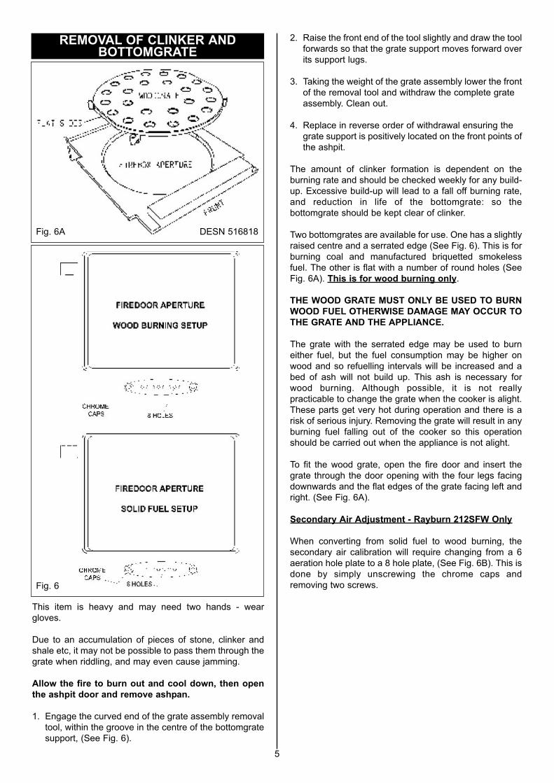
This item is heavy and may need two hands - wear
gloves.
Due to an accumulation of pieces of stone, clinker and
shale etc, it may not be possible to pass them through the
grate when riddling, and may even cause jamming.
Allow the fire to burn out and cool down, then open
the ashpit door and remove ashpan.
1. Engage the curved end of the grate assembly removal
tool, within the groove in the centre of the bottomgrate
support, (See Fig. 6).
2. Raise the front end of the tool slightly and draw the tool
forwards so that the grate support moves forward over
its support lugs.
3. Taking the weight of the grate assembly lower the front
of the removal tool and withdraw the complete grate
assembly. Clean out.
4. Replace in reverse order of withdrawal ensuring the
grate support is positively located on the front points of
the ashpit.
The amount of clinker formation is dependent on the
burning rate and should be checked weekly for any build-
up. Excessive build-up will lead to a fall off burning rate,
and reduction in life of the bottomgrate: so the
bottomgrate should be kept clear of clinker.
Two bottomgrates are available for use. One has a slightly
raised centre and a serrated edge (See Fig. 6). This is for
burning coal and manufactured briquetted smokeless
fuel. The other is flat with a number of round holes (See
Fig. 6A). This is for wood burning only.
THE WOOD GRATE MUST ONLY BE USED TO BURN
WOOD FUEL OTHERWISE DAMAGE MAY OCCUR TO
THE GRATE AND THE APPLIANCE.
The grate with the serrated edge may be used to burn
either fuel, but the fuel consumption may be higher on
wood and so refuelling intervals will be increased and a
bed of ash will not build up. This ash is necessary for
wood burning. Although possible, it is not really
practicable to change the grate when the cooker is alight.
These parts get very hot during operation and there is a
risk of serious injury. Removing the grate will result in any
burning fuel falling out of the cooker so this operation
should be carried out when the appliance is not alight.
To fit the wood grate, open the fire door and insert the
grate through the door opening with the four legs facing
downwards and the flat edges of the grate facing left and
right. (See Fig. 6A).
Secondary Air Adjustment - Rayburn 212SFW Only
When converting from solid fuel to wood burning, the
secondary air calibration will require changing from a 6
aeration hole plate to a 8 hole plate, (See Fig. 6B). This is
done by simply unscrewing the chrome caps and
removing two screws.
5
REMOVAL OF CLINKER ANDBOTTOMGRATE
Fig. 6A DESN 516818
Fig. 6

WARNING: HOT SURFACES, use the tool supplied to
operate this appliance. It is recommended to use the
heatproof glove supplied when raising the dome lids to
use the hotplate. Replacement gloves can be obtained
from the AGA Shop
The best results can only be obtained by using machined
base utensils. The hottest part of the hotplate is
immediately above the fire, the other end being for
simmering.
The circular plug in the hotplate (near the flue chamber
end) is for flue cleaning and must not be removed for
cooking.
NOTE: TO OBTAIN HOTPLATE PERFORMANCE FOR
FAST BOILING OR HOTPLATE COOKING, FUEL THE
FIREBOX APERTURE TO A HORIZONTAL LEVEL .
WARNING: THE COOKER TOP PLATE SURFACE
AROUND THE HOTPLATE WILL BECOME HOT UNDER
USE AND CARE MUST BE OBSERVED. PLEASE
REFER TO THE INSTALLATION INSTRUCTIONS
REGARDING MINIMUM CLEARANCES TO
COMBUSTIBLE SURFACES AND MATERIALS.
WARNING: DO NOT EXCEED OVEN TEMPERATURE
OF 250ºC. THIS MAY CAUSE DAMAGE TO THE
APPLIANCE.
The thermodial is an indication of the oven temperature
but should not be relied upon as an accurate
measurement of temperature. Use an oven thermometer
to calibrate the thermodial.
The correct adjustment of the spinwheel and flue chamber
damper to obtain the oven temperature required varies
with the chimney draught and can be found only be
experiment. The following is a suggested method only,
and may need modification to suit local conditions.
Suppose an oven temperature for roasting is desired and
that the cooker is idling. Thoroughly de-ash the fire as
described in the respective paragraph, and re-fuel.
Set the flue chamber damper to No.3 setting, and open
the spinwheel as described under ‘Control Setting’.
As soon as the fire has become red all through, close the
flue chamber damper. Do not allow the fire to become
white hot.
The temperature of the oven should now rise steadily.
When it reaches a point about 30ºC (50ºF) below that
required, close the spinwheel to approximately one turn
open. Thereafter control the temperature of the oven by
adjusting the spinwheel.
The main oven may take 2 hours to come to temperature.
To maintain control for cooking purposes top-up the
firebox with 1-2 kgs of fuel and lightly de-ash. Maintain the
firebox about 1/3 - 1/2 full but this will be best observed
through experience.
NOTE: THE APPLIANCE SHOULD PROVE
SUCCESSFUL IN ALMOST ALL CASES, BUT IF
CLOSING THE FLUE CHAMBER DAMPER CAUSES
THE FIRE TO SMOKE, IT SHOULD BE OPENED
GRADUALLY UNTIL THE SMOKING STOPS.
To reduce top heat in the oven, place the solid plain shelf
on the top or second pair of oven runners. The oven may
be cleaned with a stiff wire brush, when it is very hot.
Check with pointer reading on oven door thermodial.
NOTE: DUE TO VARYING SITE CONDITIONS NON-
BOILER MODELS MAY RUN AT HIGHER
TEMPERATURES THAN QUOTED ABOVE.
The oven is primarily intended for heating plates and
keeping food warm. As a guide it is around 1/3-1/2 of the
temperature of the main oven.
NOTE: THE DOORS SHOULD NOT BE SLAMMED
SHUT OR THIS WILL WEAR AWAY THE METAL
RETAINING CATCHES
When burning coke, anthracite and other smokeless
fuels, the appliance flueway should be cleaned on a
regular four weekly basis.
When burning bituminous coal or wood, cleaning should
be done at weekly intervals.
Failure to ensure clean flueways, flue pipe and bends
may lead to emission of dangerous gases and an inferior
performance from your appliance.
Allow the fire to burn out. Open the flue chamber damper
to its maximum and remove the flue chamber door.
Brush the soot or fly ash from the flue pipe allowing it to
fall onto the top of the oven.
Remove the hotplate plug and rake the deposits forward,
pushing them into the firebox. Figs. 7, 8 & 9.
Replace the flue chamber door and hotplate plug and
riddle the bottomgrate for re-lighting.
NOTE: THE APPLIANCE IS DESIGNED AND
INTENDED TO BE UNDER CONTINUOUS FIRING BUT
IF IT IS NOT IN USE, ASHPIT AND FLUE CHAMBER
DOOR SHOULD BE LEFT OPEN TO ENSURE FREE
PASSAGE OF AIR THROUGH THE APPLIANCE AND
AVOID CONDENSATION PROBLEMS.
6
USE OF THE HOTPLATE
MAIN OVEN
Setting Oven Temperature
HOT
MODERATE
SLOW
220ºC < (400ºF<)
160-220ºC (320ºF-400ºF)
<160ºC (<320ºF)
WARMING OVEN
FLUEWAY CLEANING
Fig. 7

.
Chimney Sweeping
Sweep annually and inspect soot box at 3 monthly
intervals and remove any deposits.
NOTE: SWEEP BRUSHES MUST BE OF THE TYPE
WITH WIRE CENTRES AND GUIDE WHEELS.
Failing to maintain your cooker properly can lead to a
chimney fire. Chimney fires occur when combustible
deposits on the inner walls of the chimney ignite. These
combustible deposits called ‘creosote’ are a natural by-
product of woodburning. A fire hazard exists if 1/4” of
creosote (or more) coats the inner walls of the chimney.
Prevention
Chimney fires do not occur in clean, intact properly
installed chimneys. Have a professional chimney sweep
clean and inspect your appliance at least once a year.
More frequent cleaning may be required, based on the
type of fuel burned, the type of appliance, and the
frequency of use. In general, an older appliance or one
that is used frequently, will require more than one cleaning
per year.
Detection
The first indication of a chimney fire is usually the noise,
a roaring sound that grows louder as the fire’s intensity
increases. Clouds of black smoke and sparks will be seen
exiting the top of the chimney, in severe fires, flames can
extend several feet about the chimney.
Action
In case of a chimney fire follow these steps but DO NOT
put yourself or others in peril:
1. Call the fire brigade immediately.
2. Get everyone out of the property.
3. Close down the air supply to the appliance i.e. the
primary air spinner and the flue damper. Limiting the
fire’s air supply will reduce its intensity. If there is a
damper in the chimney connector, plug or close the
opening.
4. If a fire extinguisher is available, open the appliance
door just enough to insert the nozzle of a 10 lb dry
chemical fire extinguisher rated for Class ABC fires.
Discharge the entire content of the extinguisher into
the appliance and shut the door.
5. If possible, wet down the roof and other outside
combustibles to prevent fires ignited by shooting
sparks and flames.
6. Closely monitor all combustible surfaces near the
chimney. During severe chimney fires, these surfaces
can become hot enough to ignite
After a chimney fire, have the chimney inspected by a
professional chimney sweep or cooker installer.
REMEMBER: BE CAREFUL OF THE HOT APPLIANCE.
To keep the vitreous enamelled surfaces bright and clean,
wipe over daily with a soapy damp cloth, followed by a
clean dry duster. If milk, fruit juice or anything containing
acid is spilt on the top plate or down the cooker, be sure
to wipe it immediately or the vitreous enamel may be
permanently discoloured. Keep a damp cloth handy while
cooking, to wipe up spills as they occur, so they do not
harden and become more difficult to remove later.
If spills do become baked on a cream cleanser can be
used. For stubborn deposits a soap impregnated pad can
be carefully used on the vitreous enamel.
In the main oven, spills and fat splashes are carbonised
at high temperature, occasionally brush off with a stiff
brush. The oven door can be removed for cleaning - do
not immerse in water, and shelves can be soaked and
cleaned with a cream cleanser.
Both insulating covers should be raised and allowed to
cool before cleaning with a soapy, damp cloth. Use a wire
brush to keep the cast iron hotplate clean. General
cleaning is best carried out when the Rayburn is cool.
IMPORTANT NOTE: AGA recommend Vitreous Enamel
Association approved cleaners for cleaning the vitreous
enamelled surfaces of this product.
But they are unsuitable for use on: chrome and stainless
steel components, including the hand-rails and their
brackets.
The insulating covers should be cleaned regularly with a
NON-ABRASIVE mild detergent, applied with a soft
(coarse free) cloth and lightly polished up afterwards with
a soft (coarse free) duster or tissue to bring it back to its
original lustre.
7
Fig. 8
Fig. 9
CHIMNEY FIRES
CLEANING

The firebricks fitted to the Rayburn 212SFW are of first
quality manufacture, and providing the cooker has been
installed and used correctly will have a reasonable life.
They are, however, expendable items and in time will
require renewal.
Replacement bricks either in sets or singly can be
obtained from your Rayburn distributor. Always quote the
manufacturing number.
The manufacturing number, which will be found on a data
plaque fixed to the appliance, should be quoted if any
questions arise in connection with this Rayburn Cooker.
Rayburn 212SFW
The cooker has been designed to provide a satisfactory
supply of domestic hot water with a normal day’s cooking,
providing the cooker is kept alight overnight and the
system, complete with lagged cylinder, conforms to the
installation instructions.
In some circumstances it may be possible to overheat the
appliance and the water inside will boil. This will be
evident by the sound of a knocking noise coming from the
appliance and pipes around the house. If this occurs close
off all air controls and manually start the central heating
pump if fitted. Opening the oven doors and hotplate
covers will help to release heat from the appliance. Be
aware that steam and boiling water will be expended from
any open vent from the heating system probably in the
roof space at the expansion tank.
In the unlikely event that the appliance is not operating in
freezing conditions the water must be drained from the
boiler to prevent frost damage.
WARNING:- If there is a possibility that a part of the
heating system may be frozen you should not light the
stove until you are confident that the system is free of ice,
has no leaks and water is able to fully circulate.
Always use a qualified service/heating engineer when
servicing or maintenance is required. Use only authorised
replacement parts. Do not make unauthorised
modifications.
Building regulations require that when ever a new or
replacement fixed solid fuel or wood/biomass appliance is
installed in a dwelling a carbon monoxide alarm must be
fitted in the same room as the appliance. Further
guidance on the installation of the carbon monoxide alarm
is available in BS EN 50292:2002 and from the alarm
manufacturer’s instructions. Provision of an alarm must
not be considered a substitute for either installing the
appliance correctly or ensuring regular servicing and
maintenance of the appliance and chimney system.
WARNING:- Your installer should have fitted a CO alarm
in the same room as the appliance. If the alarm sounds
unexpectedly, follow the instructions given under
“Warning Note” above.
Properly installed and operated, this cooker will not emit
fumes.
Occasional fumes from de-ashing and re-fuelling may
occur but persistent fume emission must not be tolerated.
If fume emission does persist, then the following
immediate action should be taken:
1. Open doors and windows to ventilate room.
2. Let the fire out or remove lit fuel from cooker.
3. Check for flue or chimney blockage, and clean if
required.
4. Do not attempt to re-light the fire until cause of fumes
has been identified, and if necessary, seek
professional advice.
If the stove is to be left unused for a prolonged period of
time then it should be given a thorough clean to remove
ash and unburned fuel residues. To enable a good flow of
air through the appliance to reduce condensation and
subsequent damage, leave the air controls fully open.
It is important that the flue connection, any appliance
baffles or throat plates and the chimney are swept prior to
lighting up after a prolonged shutdown period.
Spares List No
Part Number Description Required
Required
RS4F 3-51-2A L.H. Side Firebrick 1
RS4F52-7A Middle L.H. Side Firebrick 1
RS4F3-54-8B Top L.H. Side Firebrick 1
RS4F 3-48-4A Bottom R.H. Side Firebrick 1
RS4F 50-5A Top R.H. Side Firebrick 1
RS4F 3-47-3A Bottom Front Firebrick 1
RS1M 90040 Ashpan 1
RSFM 61 Operating Tool 1
Replacement parts if required are available from your
local stockists.
8
FIREBRICK REPLACEMENT
HOT WATER SERVICE
SERVICING
CO ALARM
FUME EMISSION WARNING
SPARE PARTS
PROLONGED NON USE

see also the ‘MAIN OVEN’.
The oven is indirectly heated from outside by hot gases
from the heat source so no flames or elements within the
ovens means full use can be made of the whole cooking
space.
The main oven is slightly hotter towards the top than the
bottom. At a low idling heat the main oven can be used
for long slow cooking such as casseroles, stock, soup,
ratatouille, curries, meringues, creme caramels, rice
puddings, etc all of which benefit from gentle slow heat
and as the oven is vented into the flue, cooking smells
disappear to the outside.
One of the many benefits of the cast iron oven is that the
floor of the oven is hotter than that of a conventional
cooker. No need to bake quiche pastry cases “blind” just
place the flan dish on the oven floor for half of the cooking
time for “soggy-free” pastry. When the oven is hot the floor
of the oven can be used for shallow frying (a cast iron dish
is recommended) with the added advantages that fat
splashes are carbonised so cleaning is minimised and the
frying smells are taken away through the flue.
For perfect baking results turn food during cooking.
The top of a hot oven is where grilling takes place, use the
meat tray with a grill rack (optional extra) so that the fat
can drip into the tray.
The thermodial gauge, on the main oven door is a guide
to the internal oven temperature. Remember though, on
opening the door the temperature will appear to drop, do
not worry, close the door and after a few minutes the true
temperature can be read again.
Heat is not lost as quickly from a cast iron oven as a
pressed metal box type so you can peep at the cake to
see how it is cooking without it sinking.
As you have probably realised, the meat tray supplied
with your Rayburn fits the oven, hanging directly from the
runners, so leaving the grid shelves free for other dishes.
The oven grid shelves are designed to be non-tilt and
should be fitted with the upstand to the top and at the
back, so when pulled forward the shelf cannot come right
out.
The solid plain shelf, as mentioned before, can be used
as a baking sheet or as a heat deflector. If the oven is too
hot or food already in the oven is beginning to overbrown
slide in the solid plain shelf, above the food. To be
effective the shelf should be stored out of the oven, so it
is used from cold.
DO NOT USE ABRASIVE PADS OR OVEN CLEANERS
NOTE: IT IS NOT ADVISABLE TO PUT VERY WET
CLOTHES ON THE HANDRAIL, AS THIS MAY CRAZE
THE ENAMEL.
NOTE: SMOKE/SMELL EMITTED DURING INITIAL
USAGE.
Some parts of the cooker have been coated with a light
covering of protective oil. During initial operation of the
cooker, this may cause smoke/smell to be emitted and is
normal and not a fault with the appliance, it is therefore
advisable to open doors and or windows to allow for
ventilation. Lift the lids to prevent staining the linings.
9
COOKING HINTS

10

11

12
For further advice or information contact your
local distributor/stockist
With AGA Rangemaster’s policy of continuous
product improvement, the Company reserves the
right to change specifications and make
modifications to the appliance described at any
time.
Manufactured by
AGA Rangemaster
Station Road
Ketley Telford
Shropshire TF1 5AQ
England
www.rayburn-web.co.uk
www.agacookshop.co.uk
www.agalinks.com