Embed Size (px)
Citation preview

INSTALLATION INSTRUCTIONSFOR GROEN CASTER KITS
Part No. 150528, Rev. A
IMPORTANT INFORMATION I KEEP FOR OPERATOR I IMPORTANT INFORMATION
Eclipse Braising Pans (Models BPM or BPP – G or E) Steamers (Models VRC, SSB or HY) Combo Ovens (Models CC-10 or C/2 – G or E) TS-9 Stands (for table top units - Kettle Models TDB, TDH,Braising Pan Model TD/FPC or Cooker Mixer TDB; TA/2)
OPERATORS AND INSTALLING TECHNICIANSSHOULD READ, UNDERSTAND AND FOLLOW
WARNINGS AND INSTRUCTIONS IN THIS MANUAL
Table of Contents
Page
Eclipse Braising Pans (Models BPM or BPP – G or E) 2
Steamers (Models VRC, SSB or HY) 4
Combo Ovens (Models CC-10 or C/2 – G or E) 7
TS-9 Stands (for table top units - Kettle Models TDB, TDH, 9Braising Pan Model TD/FPC or Cooker Mixer TDB; TA/2)
This Restraining Device Must Always Be Connected
When the Appliance with Casters is in Service
Disconnect Then ReconnectOnly For Maintenance
This restraining device is required for all units with casters or per one of the following standards:
1. UL/ANSI 1972. ANSI Z83.11/ CSA 1.8
GROEN CASTER KIT
1

INSTALLATION INSTRUCTIONSFOR GROEN CASTER KIT (Groen Part #146354)
ECLIPSE BRAISING PANS
WARNING:
1. WHEN INSTALLING ON A GAS BRAISING PAN, THESE CASTERS MUST BE INSTALLED WITH A GROEN GAS QUICK DISCONNECT SUPPLY KIT (GROEN PART #140144) OR A GAS HOSE WITH MAXIMUM LENGTH THAT IS LONGER THAN THE RESTRAINING CABLE.2. WHEN INSTALLING ON AN ELECTRIC BRAISING PAN, LENGTH OF FLEXIBLE CONDUIT MUST BE LONGER THAN THE RESTRAINING CABLE.
INSTALLATION PROCEDURE-
1. Raise the braising pan about 8”above the ground.
2. Unscrew and remove the factory installed bullet feet.
3. Screw in casters into place.
4. Level the braising pan front to back and left to right by adjusting the casters accordingly.
Figure 1
5. Anchor the restraining cable bracket to a secure structure. One of the preferred locations is on the concrete floor using anchor bolts (not provided) as shown in Figure 1.
GROEN CASTER KIT
2
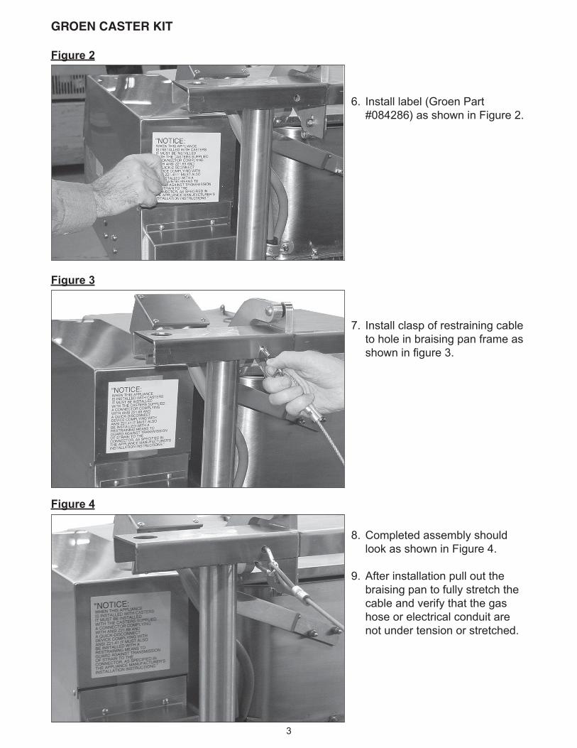
Figure 2
GROEN CASTER KIT
6. Install label (Groen Part #084286) as shown in Figure 2.
7. Install clasp of restraining cable to hole in braising pan frame as shown in figure 3.
Figure 3
Figure 4
8. Completed assembly should look as shown in Figure 4.
9. After installation pull out the braising pan to fully stretch the cable and verify that the gas hose or electrical conduit are not under tension or stretched.
3

GROEN CASTER KIT
INSTALLATION INSTRUCTIONSFOR GROEN CASTER KIT (Groen Part #098611)
SSB, VRC AND HY STANDS
NOTE: DO NOT INSTALL CASTERS ON HYPLUS MODELS
WARNING:
1. WHEN INSTALLING ON A GAS STEAMER, THESE CASTERS MUST BE INSTALLED WITH A GROEN GAS QUICK DISCONNECT SUPPLY KIT (GROEN PART #140144 OR A GAS HOSE WITH MAXIMUM LENGTH THAT IS LONGER THAN THE RESTRAINING CABLE.
2. WHEN INSTALLING ON AN ELECTRIC STEAMER, LENGTH OF FLEXIBLE CONDUIT MUST BE LONGER THAN THE RESTRAINING CABLE.
INSTALLATION PROCEDURE-
1. Raise the steamer stand about 8”above the ground. WARNING: Support the steamer securely before lifting so that it does not tilt.
2. Remove the factory installed bullet feet.
3. Insert casters into place.
4. Level the steamer front to back and left to right by adjusting the casters accordingly.
Figure 5
5. Drill a 13/32” (0.406” or 9 mm) diameter hole through one of the rear legs of table approximately 3” to 6” below the top of table as shown In Figure 5 (single stack units) or Figure 6 (double stack units).
6. Attach eyebolt, washers, lockwasher and nut to the table as shown in Figure 5.
4
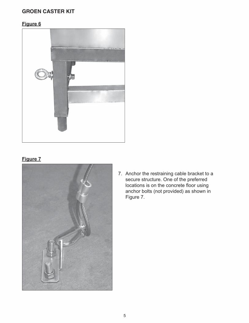
Figure 6
Figure 7
GROEN CASTER KIT
7. Anchor the restraining cable bracket to a secure structure. One of the preferred locations is on the concrete floor using anchor bolts (not provided) as shown in Figure 7.
5
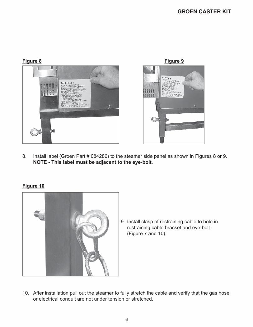
Figure 8 Figure 9
8. Install label (Groen Part # 084286) to the steamer side panel as shown in Figures 8 or 9. NOTE - This label must be adjacent to the eye-bolt.
Figure 10
9. Install clasp of restraining cable to hole in restraining cable bracket and eye-bolt (Figure 7 and 10).
10. After installation pull out the steamer to fully stretch the cable and verify that the gas hose or electrical conduit are not under tension or stretched.
GROEN CASTER KIT
6
INSTALLATION INSTRUCTIONSFOR GROEN CASTER KIT (Groen Part #098611)
CC10 AND C/2 STANDSWARNING:
1. WHEN INSTALLING ON A GAS COMBO OVEN, THESE CASTERS MUST BE INSTALLED WITH A GROEN GAS QUICK DISCONNECT SUPPLY KIT (GROEN PART #140144) OR A GAS HOSE WITH MAXIMUM LENGTH THAT IS LONGER THAN THE RESTRAINING CABLE.
2. WHEN INSTALLING ON AN ELECTRIC COMBO OVEN, LENGTH OF FLEXIBLE CONDUIT MUST BE LONGER THAN THE RESTRAINING CABLE.
INSTALLATION PROCEDURE-
1. Raise the combo oven stand about 8” above the ground. WARNING: Support the combination oven securely before lifting so that it does not tilt.2. Remove the factory installed bullet feet.3. Insert casters into place.4. Level the combo oven front to back and left to right by adjusting the casters accordingly.
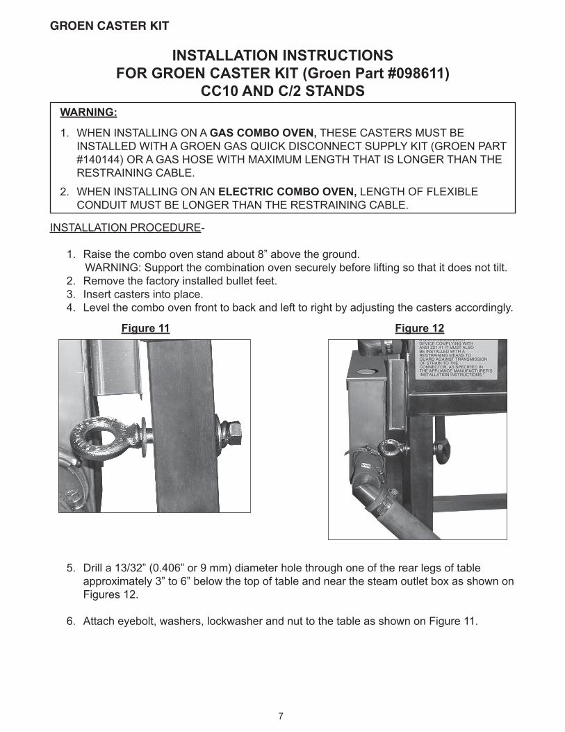
Figure 11 Figure 12
5. Drill a 13/32” (0.406” or 9 mm) diameter hole through one of the rear legs of table approximately 3” to 6” below the top of table and near the steam outlet box as shown on Figures 12.
6. Attach eyebolt, washers, lockwasher and nut to the table as shown on Figure 11.
GROEN CASTER KIT
7
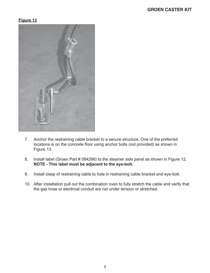
Figure 13
7. Anchor the restraining cable bracket to a secure structure. One of the preferred locations is on the concrete floor using anchor bolts (not provided) as shown in Figure 13.
8. Install label (Groen Part # 084286) to the steamer side panel as shown in Figure 12. NOTE - This label must be adjacent to the eye-bolt.
9. Install clasp of restraining cable to hole in restraining cable bracket and eye-bolt.
10. After installation pull out the combination oven to fully stretch the cable and verify that the gas hose or electrical conduit are not under tension or stretched.
GROEN CASTER KIT
8
INSTALLATION INSTRUCTIONSFOR GROEN CASTER KIT ON
TS-9 STAND FOR TABLE TOP KETTLES
WARNING:
1. WHEN INSTALLING ON A TABLE WITH GAS KETTLE, THESE CASTERS MUST BE INSTALLED WITH A GROEN GAS QUICK DISCONNECT SUPPLY KIT (GROEN PART #140144) OR A GAS HOSE WITH MAXIMUM LENGTH THAT IS LONGER THAN THE RESTRAINING CABLE.
2. WHEN INSTALLING ON A TABLE WITH ELECTRIC KETTLE, LENGTH OF FLEXIBLE CONDUIT MUST BE LONGER THAN THE RESTRAINING CABLE.
INSTALLATION PROCEDURE-
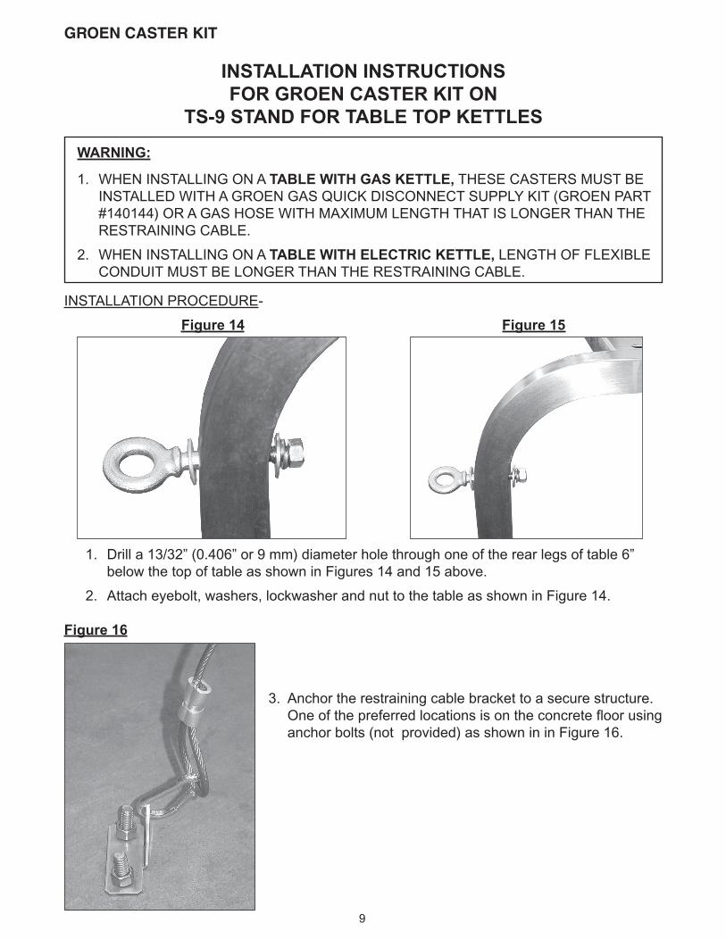
Figure 14 Figure 15
1. Drill a 13/32” (0.406” or 9 mm) diameter hole through one of the rear legs of table 6” below the top of table as shown in Figures 14 and 15 above.
2. Attach eyebolt, washers, lockwasher and nut to the table as shown in Figure 14.
Figure 16
3. Anchor the restraining cable bracket to a secure structure. One of the preferred locations is on the concrete floor using anchor bolts (not provided) as shown in in Figure 16.
GROEN CASTER KIT
9
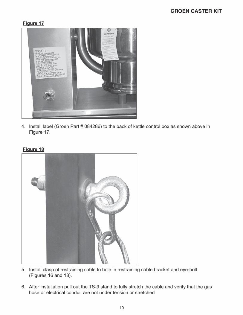
Figure 17
4. Install label (Groen Part # 084286) to the back of kettle control box as shown above in Figure 17.
Figure 18
5. Install clasp of restraining cable to hole in restraining cable bracket and eye-bolt (Figures 16 and 18).
6. After installation pull out the TS-9 stand to fully stretch the cable and verify that the gas hose or electrical conduit are not under tension or stretched
GROEN CASTER KIT
10

1055 Mendell Davis Drive
Jackson, MS 39272
Telephone 601 372-3903
Fax 601 373-9587
www.groen.com
INSTALLATION INSTRUCTIONSFOR GROEN CASTER KITS
Part No. 150528, Rev. A