Embed Size (px)
Citation preview

PK-93827-10-02-2A
Single Pole (One location)5 Button Countdown Timer
Cat No. 6161T - 120VAC, 60Hz, 500W Incandescent Cat. Nos. LTT15, LTT60, LTT30, LTT12
120VAC, 60Hz, 600W Incandescent, 5A Resistive, 5A TungstenINSTALLATION INSTRUCTIONS
Unipolaire (un emplacement)Minuterie de compte à rebours à cinq boutons
No de Cat. 6161T – 120 V c.a., 60 Hz, 500 W (à incandescence)Nos de cat. LTT15, LTT60, LTT30, LTT12 - 120 V c.a., 60 Hz, 600 W (à incandescence), 5 A (résistive), 5 A (au tungstène)
DIRECTIVES D’INSTALLATION
Unipolar (1 Ubicación)Cronómetro de cuenta regresiva de 5 botones No. de Cat. 6161T – 120VCA, 60Hz, 500W Incandescente
Nos. de Cat. LTT15, LTT60, LTT30, LTT12 - 120VCA, 60Hz, 600W Incandescente, 5A Resistivo, 5A Tungsteno
INSTRUCCIONES DE INSTALACION
AVERTISSEMENT : pour éviter les risques d’incendie, de choc électrique ou d’électrocution, COUPER LE COURANT au fusible ou au disjoncteur et s’assurer que le circuit soit bien coupé avant de procéder au câblage.
WARNINGS AND CAUTIONS:• Tobeinstalledand/orusedinaccordancewithelectricalcodesandregulations.• Ifyouareunsureaboutanypartoftheseinstructions,consultanelectrician.• Toavoidoverheatingandpossibledamagetothisdeviceandotherequipment,
donotinstalltocontrolareceptacle,fluorescentlighting,amotor-oratransformer-operated appliance.
• Usewithincandescentor120Vhalogenfixturesonly.• Totalminimumloadmustexceed40W.• Recommendedminimumwallboxdepthis2-1/2”.• Disconnectpoweratcircuitbreakerorfusewhenservicing,installingorremovingfixture.• UsethisdeviceWITH COPPER OR COPPER CLAD WIRE ONLY.
Tools needed to install your TimerSlotted/PhillipsScrewdriver ElectricalTapePliers PencilCutters Ruler
Installing your Timer
√NOTE: UsecheckboxeswhenStepsarecompleted.
Installation√REMARQUE: cocher les cases une fois les étapes complétées.
ONOFF
ONOFF
ONOFF
ONOFF
ONOFF
ONOFF
ONOFFONOFF
ONOFF
ONOFF
ONOFF
ONOFF
Step 1 WARNING: TO AVOID FIRE, SHOCK, OR DEATH; TURN OFF POWER atcircuitbreakerorfuseandtestthatpowerisoffbeforewiring!
• S’assurerquelesbrinsdesfilsdelaboîtemuralesoientbiendroits (les recouper au besoin).
• Dénuderl’extrémitédechaquefildelaboîtemuraledelamanièreillustrée.
Préparation et raccordement des fils :
Gabarit de dénudage (pour mesurer les fils dénudés)
1.6 cm(5/8")
Couper(au besoin)
Étape 3
ONOFF
ONOFF
ONOFF
ONOFF
ONOFF
ONOFF
ONOFFONOFF
ONOFF
ONOFF
ONOFF
ONOFF
Étape 1
2
43
1
Single-Pole1. Line (Hot)2. Neutral3. Ground4. Load
NOTE: A neutral connection is notrequired for this device.
Identification de l’application (plus courantes montrées) :REMARQUE :silesraccordsàl’intérieurdelaboîteneressemblentpasdutoutàceuxmontrésici,ondoitfaireappelàunélectricienqualifié.
Étape 2
2
43
1
Unipolaire1. Ligne (actif)2. Neutre3. Terre4. Charge
REMARQUE: ce dispositif ne requiert pas de raccordement au neutre.
Step 2 Identifying your wiring application (most common):NOTE:Ifthewiringinthewallboxdoesnotresembleanyoftheseconfigurations,consultaqualifiedelectrician.
Preparing and connecting wires:
• Makesurethattheendsofthewiresfromthewallboxarestraight (cut if necessary).• Removeinsulationfromeachwireinthewallboxasshown.
Strip Gage (measure bare wire here or use gage on back of the timer)
5/8"(1.6 cm)
Cut(if necessary)
Step 3
Single-Pole Wiring Application:Connect wires per WIRING DIAGRAM as follows:Twiststrandsofeachleadtightlyand,withcircuitconductors,pushfirmlyintoappropriatewireconnector.Screwconnectorsonclockwisemakingsurethatnobarewireshowsbelowthewireconnectors.Secureeachwireconnectorwithelectricaltape.
Step 4
Timer
Hot (Black) Black
Black
Black
Neutral (White)
Line120VAC
60Hz
White
GreenGround
Load
Restore Power: Restorepoweratcircuitbreakerorfuse.Installation is complete. Step 7
Timer Mounting:TURN OFF POWER AT CIRCUIT BREAKER OR FUSE.
Step 6
Installationmaynowbecompletedbytighteningmountingscrewsintowallbox.Attachwallplate.
NOTE: Dresswireswithabendasshownindiagraminordertorelievestresswhenmountingdevice.
Testing your Timer prior to mounting in wall box: Step 5
• Restorepoweratcircuitbreakerorfuse.• Makesureslideswitchisinthe(ON)position-
located to the right (see OPERATION). Press anyoneofthetimerbuttonsandthelightswillturn ON.
If lights DO NOT turn ON refer to Troubleshooting section.
• Positionallwirestoprovideroominoutletwallboxfor device.
• Ensurethattheword“TOP”isfacingupondevicestrap.
• Partiallyscrewinmountingscrewsinwallboxmounting holes.
1. ToturnthelightsONpressoneofthetimeoutbuttons.ThiswillcommencetimecountdownandthegreenLEDnexttothatbuttonwillturnon.
2. ToturnthelightsOFFwaituntiltheselectedtimehaspassed(theLEDnexttoeachbuttonwillextinguishastimeoutpassestothenextpresetlevel)orpresstheOFFbutton.
3. PressingandholdingthetopbuttonuntilallLEDsturnonwilloverridethetimeoutfeatureandthelightswillstayonuntilatimeoutbuttonortheOFFbuttonispressed.
OPERATION
• Lights and LED do not turn ON - Checkwiring - Checktoseeifcircuitbreakerorfusehastripped - CheckthatslideswitchisintheONposition(locatedtotheright)
TROUBLESHOOTING
Button 4/Override switch
Button 3Green LED indicator
lights Button 2
Button 1
OFF switch
ON/OFF slide switch
Outils requisTournevisordinaire/Phillips Rubanisolant Pinces Crayon Coupe-fil Règle
DIRECTIVES D’INSTALLATION FRANÇAISAVERTISSEMENTS ET MISES EN GARDE :• Installerouutiliserconformémentauxcodesdel’électricitéenvigueur.• Àdéfautdebiencomprendrelesprésentesdirectives,entoutouenpartie,ondoitfaire
appelàunélectricienqualifié.• Pouréviterlasurchauffeoul’endommagementéventueldecedispositifetdes
appareils qui lui sont raccordés, ne pas l’installer pour commander une prise, de l’éclairagefluorescentouunappareilmotoriséouàtransformateur.
• N’utilisercedispositifqu’enprésenced’appareilsd’éclairageàincandescenceouàhalogène de 120 V
• Lachargetotaleminimaledoitêtresupérieureà40W.• Profondeurrecommandéepourlaboîtemurale:6,4cm(21/2po).• Couperl’alimentationaufusibleouaudisjoncteuravantdemanipuler,d’installeroude
retirer les luminaires commandés.• N’utilisercedispositifqu’avecduFIL DE CUIVRE OU PLAQUÉ CUIVRE.
Si la minuterie est installée seule, passer à la section INSTALLATION. Si elle est groupée avec d’autres dispositifs, procédercommesuit:
Installation de la minuterie seule, ou avec d’autres dispositifs
INSTALLATIONS GROUPÉESLorsque ce dispositif est installé en groupe, on doit en réduire la capacité nominale. Se reporter au tableau CHARGE MAXIMALE/MINUTERIE.
Applications unipolaires:Raccorder les fils conformément au schéma de câblage et de la façon suivante : torsader solidement ensemble les brins de chaqueconnexionetenfoncerfermementleraccorddansunserre-filsdecalibreapproprié,entournantcedernierversladroiteetens’assurantqu’aucunbrindecuivrenesoitexposé.Protégerlesraccordsaumoyenderubanisolant.
Minuterie
Actif (Noir) Noir
Noir
Noir
Neutre (Blanc)
Ligne120 V c.a.
60Hz
Blanc
Terrevert
Charge
Étape 4
Product Button 1 Button 2 Button 3 Button 4 Time
6161T(10,20,30,60M) 10 20 30 60 Minutes
LTT15(2,5,10,15M) 2 5 10 15 Minutes
LTT30(5,10,15,30M) 5 10 15 30 Minutes
LTT60(10,20,30,60M) 10 20 30 60 Minutes
LTT12(2,4,8,12H) 2 4 8 12 Hour
NOTE:EnsureslideswitchisintheOFFpositionwhenchangingthebulb.MULTI-DEVICE APPLICATIONInmulti-deviceinstallations,thereductionofthetimer’scapacityisrequired.Refertothechartformaximumloadpertimer.
IfinstallingTimerinasingledeviceapplication,proceedwiththeINSTALLING YOUR TIMERsection.IfinstallingTimerinamulti-deviceapplication,proceedasfollows:
Installing Timer by itself or with other devices
MAXIMUM LOAD PER TIMER FOR MULTI-DEVICE
Cat. No.
LTT15, LTT30, LTT60, LTT12
Single
500W
600W
Two Devices
300W
500W
More than 2 Devices
250W
400W
6161T
• Degreeofprotection: IP20• TypeofAction: 1.B.Q
Un dispositif Deux dispositifs Plus de 2 dispositifs
CHARGE MAXIMALE/MINUTERIE
No de cat.
LTT15, LTT30, LTT60, LTT12
500W
600W
300W
500W
250W
400W
6161T
©2009LevitonMfg.Co.,Inc. PK-93827-10-02-2A
LIMITED 5 YEAR WARRANTY AND EXCLUSIONSLevitonwarrants to the original consumer purchaser and not for the benefit of anyone else thatthis product at the time of its sale by Leviton is free of defects in materials and workmanshipunder normal and proper use for five years from the purchase date. Leviton’s only obligationis to correct such defects by repair or replacement, at its option, if within such five year periodtheproduct is returnedprepaid,withproofofpurchasedate,andadescriptionof theproblem toLeviton Manufacturing Co., Inc., Att: Quality Assurance Department, 201 North Service Road, Melville, N.Y. 11747.Thiswarrantyexcludesandthere isdisclaimedliability for laborforremovalof this product or reinstallation. This warranty is void if this product is installed improperly or inan improperenvironment,overloaded,misused,opened,abused,oraltered inanymanner,or isnot usedundernormaloperating conditionsornot inaccordancewithany labelsor instructions.There are no other or implied warranties of any kind, including merchantability and fitness for a particular purpose,butifanyimpliedwarrantyisrequiredbytheapplicablejurisdiction,thedurationofanysuchimpliedwarranty,includingmerchantabilityandfitnessforaparticularpurpose,is limitedtofiveyears.Leviton is not liable for incidental, indirect, special, or consequential damages, including without limitation, damage to, or loss of use of, any equipment, lost sales or profits or delay or failure to perform this warranty obligation. The remedies provided hereinaretheexclusiveremediesunderthiswarranty,whetherbasedoncontract,tortorotherwise.
REMARQUE: donnerauxfilslerayondecourbureindiquédansleschémaafinderéduire les contraintes lors de l’insertion dudispositiflui-même.
Vérification de la minuterie avant son installation complète dans la boîte murale :
• Rétablirl’alimentationaufusibleouaudisjoncteur.• S’assurerquelaglissièredecommutationsoità
la bonne position (à droite, se reporter à la section FONCTIONNEMENT).Appuyersurn’importequelboutonde minuterie pour allumer les lumières.
Si les lumières ne s’allument PAS, se reporter à la section Diagnostic des anomalies.
• Insérertouslesfilsdanslaboîte,enprévoyantsuffisammentd’espacepourledispositif.
• S’assurer que les mots « TOP » sur la bride du dispositif vers le haut.
• Serrer partiellement les vis de montage dans les trousdelaboîte.
Étape 5
Fixation de la minuterie : Étape 6
L’installationpeutmaintenantêtrefinaliséeenserrantlesvisdemontagesurlaboîte.Fixerlaplaquemurale.
FONCTIONNEMENT
Bouton 4/commande prioritaire
Bouton 3Témoins lumineux
verts
Glissière de commutation
Bouton 2
Bouton 1
Mise hors tension
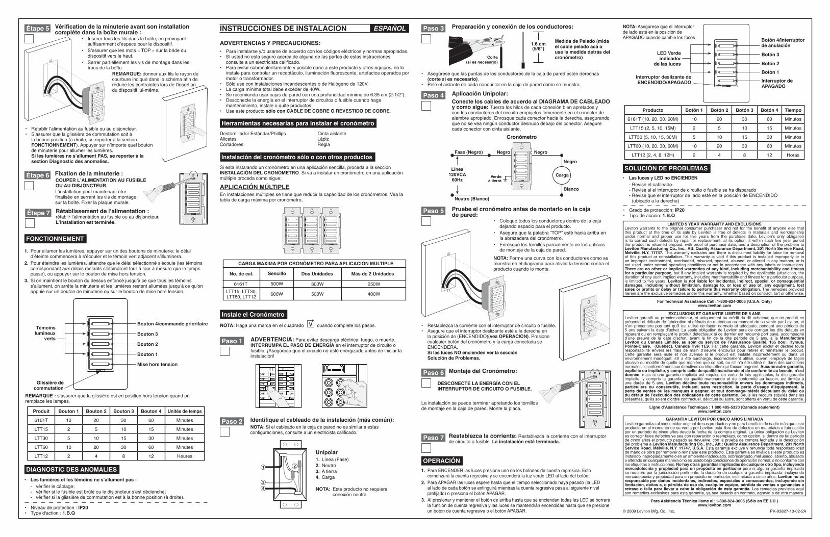
Instale el Cronómetro√NOTA: Haga una marca en el cuadrado cuando complete los pasos.
• Asegúresequelaspuntasdelosconductoresdelacajadeparedesténderechas(corte si es necesario).
• Peleelaislantedecadaconductorenlacajadeparedcomosemuestra.
Preparación y conexión de los conductores:
Medida de Pelado (mida el cable pelado acá o use la medida detrás del cronómetro)
1.6 cm(5/8")
Corte(si es necesario)
Identifique el cableado de la instalación (más común):NOTA: Si el cableado en la caja de pared no es similar a estas configuraciones,consulteaunelectricistacalificado.
2
43
1
Unipolar1. Línea (Fase)2. Neutro3. A tierra4. Carga
NOTA: Esteproductonorequiereconexiónneutra.
Herramientas necesarias para instalar el cronómetroDestornilladorEstándar/Phillips Cintaaislante Alicates Lápiz Cortadores Regla
Siestáinstalandouncronómetroenunaaplicaciónsencilla,procedaalasecciónINSTALACIÓN DEL CRONÓMETRO. Si va a instalar un cronómetro en una aplicación múltipleprocedacomosigue:
Instalación del cronómetro sólo o con otros productos
ADVERTENCIAS Y PRECAUCIONES:• Parainstalarsey/ousarsedeacuerdoconloscódigoseléctricosynormasapropiadas.• Siustednoestaseguroacercadealgunadelaspartesdeestasinstrucciones,
consulteaunelectricistacalificado.• Paraevitarsobrecalentamientoyposibledañoaesteproductoyotrosequipos,nolo
instaleparacontrolarunreceptáculo,iluminaciónfluorescente,artefactosoperadospormotor o transformador.
• SólouseconinstalacionesincandescentesodeHalógenode120V.• Lacargamínimatotaldebeexcederde40W.• Serecomiendausarcajasdeparedconunaprofundidadmínimade6.35cm(2-1/2").• Desconectelaenergíaenelinterruptordecircuitosofusiblecuandohaga
mantenimiento, instale o quite productos.• Useesteproductosólo con CABLE DE COBRE O REVESTIDO DE COBRE.
APLICACIÓN MÚLTIPLEEninstalacionesmúltiplessetienequereducirlacapacidaddeloscronómetros.Vealatabladecargamáximaporcronómetro.
Paso 2
Paso 7
Paso 3
Aplicación Unipolar:Conecte los cables de acuerdo al DIAGRAMA DE CABLEADO y como sigue: Tuerzaloshilosdecadaconexiónbienapretadosyconlosconductoresdelcircuitoempújelosfirmementeenelconectordealambreapropiado.Enrosquecadaconectorhacialaderecha,asegurandoquenoseveaningúnconductordesnudodebajodelconector.Asegurecada conector con cinta aislante.
Cronómetro
Fase (Negro) Negro
Negro
Negro
Neutro (Blanco)
Línea120VCA
60Hz
Blanco
Verdea tierra
Carga
Paso 4
Pruebe el cronómetro antes de montarlo en la caja de pared:
• Restablezcalacorrienteconelinterruptordecircuitoofusible.• Asegurequeelinterruptordeslizanteestéaladerechaen
laposiciónde(ENCENDIDO)(vea OPERACION). Presione cualquierbotóndelcronómetroylacargaconectadaseENCENDERA.
Si las luces NO encienden ver la secciónSolución de Problemas.
• Coloque todos los conductores dentro de la caja dejando espacio para el producto.
• Asegurequelapalabra“TOP”estéhaciaarribaenla abrazadera del cronómetro.
• Enrosquelostornillosparcialmenteenlosorificiosde montaje de la caja de pared.
Paso 5
ONOFF
ONOFF
ONOFF
ONOFF
ONOFF
ONOFF
ONOFFONOFF
ONOFF
ONOFF
ONOFF
ONOFF
Paso 1 ADVERTENCIA: Para evitar descarga eléctrica, fuego, o muerte, INTERRUMPA EL PASO DE ENERGÍA en el interruptor de circuito o fusible.¡Asegúresequeelcircuitonoestéenergizadoantesdeiniciarlainstalación!
Restablezca la corriente: Restablezca la corriente con el interruptor de circuito o fusible. La instalación está terminada.
Botón 4/Interruptor de anulación
Botón 3LED Verde indicador
de las luces
Interruptor deslizante de ENCENDIDO/APAGADO
Botón 2
Botón 1
Interruptor de APAGADO
For Technical Assistance Call: 1-800-824-3005 (U.S.A. Only)www.leviton.com
EXCLUSIONS ET GARANTIE LIMITÉE DE 5 ANSLeviton garantit au premier acheteur, et uniquement au crédit du dit acheteur, que ce produit ne présentenidéfautsdefabricationnidéfautsdematériauxaumomentdesaventeparLeviton,etn’en présentera pas tant qu’il est utilisé de façon normale et adéquate, pendant une période de 5 ans suivant la date d’achat. La seule obligation de Leviton sera de corriger les dits défauts en réparantouenremplaçantleproduitdéfectueuxsicedernierestretournéportpayé,accompagnéd’une preuve de la date d’achat, avant la fin de la dite période de 5 ans, à la Manufacture Leviton du Canada Limitée, au soin du service de l’Assurance Qualité, 165 boul. Hymus, Pointe-Claire, (Québec), Canada H9R 1E9. Par cette garantie, Leviton exclut et décline touteresponsabilité envers les frais de main d’oeuvre encourus pour retirer et réinstaller le produit. Cette garantie sera nulle et non avenue si le produit est installé incorrectement ou dans un environnement inadéquat, s’il a été surchargé, incorrectement utilisé, ouvert, employé de façonabusiveoumodifiédequellequemanièrequecesoit,ous’iln’aétéutilisénidansdesconditionsnormalesniconformémentauxdirectivesouétiquettesquil’accompagnent.Aucune autre garantie, explicite ou implicite, y compris celle de qualité marchande et de conformité au besoin, n’est donnée, mais si une garantie implicite est requise en vertu de lois applicables, la dite garantie implicite, y compris la garantie de qualité marchande et de conformité au besoin, est limitée àune durée de 5 ans. Leviton décline toute responsabilité envers les dommages indirects, particuliers ou consécutifs, incluant, sans restriction, la perte d’usage d’équipement, la perte de ventes ou les manques à gagner, et tout dommage-intérêt découlant du délai ou du défaut de l’exécution des obligations de cette garantie. Seuls les recours stipulés dans les présentes, qu’ils soient d’ordre contractuel, délictuel ou autre, sont offerts en vertu de cette garantie.
GARANTIA LEVITON POR CINCO AÑOS LIMITADALevitongarantizaalconsumidororiginaldesusproductosynoparabeneficiodenadiemásqueesteproductoenelmomentodesuventaporLevitonestálibrededefectosenmaterialesofabricaciónporunperíododecincoañosdesdelafechadelacompraoriginal.LaúnicaobligacióndeLevitonescorregirtalesdefectosyaseaconreparaciónoreemplazo,comoopción,sidentrodetalperíododecincoañoselproductopagadosedevuelve,conlapruebadecomprafechadayladescripcióndel problema a Leviton Manufacturing Co., Inc., Att.: Quality Assurance Department, 201 North Service Road, Melville, N.Y. 11747, U.S.A.Estagarantíaexcluyeyrenunciatodaresponsabilidaddemanodeobraporremoveroreinstalaresteproducto.Estagarantíaesinválidasiesteproductoesinstalado inapropiadamente o en un ambiente inadecuado, sobrecargado, mal usado, abierto, abusado o alterado en cualquier manera o no es usado bajo condiciones de operación normal, o no conforme con las etiquetas o instrucciones. No hay otras garantías implicadas de cualquier otro tipo, incluyendo mercadotecnia y propiedad para un propósito en particular pero si alguna garantía implicada serequiereporlajurisdicciónpertinente,laduracióndecualquieragarantíaimplicada,incluyendomercadotecniaypropiedadparaunpropósitoenparticular,eslimitadaacincoaños.Leviton no es responsable por daños incidentales, indirectos, especiales o consecuentes, incluyendo sin limitación, daños a, o pérdida de uso de, cualquier equipo, pérdida de ventas o ganancias o retraso o falla para llevar a cabo la obligación de esta garantía. Los remedios provistos aquí sonremediosexclusivosparaestagarantía,yaseabasadoencontrato,agravioodeotramanera.
Ligne d’Assistance Technique : 1 800 405-5320 (Canada seulement)www.leviton.com
Para Asistencia Técnica llame al: 1-800-824-3005 (Sólo en EE.UU.)www.leviton.com
INSTRUCCIONES DE INSTALACION ESPAÑOL
1. Pourallumerleslumières,appuyersurundesboutonsdeminuterie;ledélaid’éteinte commencera à s’écouler et le témoin vert adjacent s’illuminera.
2. Pour éteindre les lumières, attendre que le délai sélectionné s’écoule (les témoins correspondantauxdélaisrestantss’éteindronttouràtouràmesurequeletempspasse),ouappuyersurleboutondemisehorstension.
3. Si on maintient le bouton du dessus enfoncé jusqu’à ce que tous les témoins s’allument,onarrêtelaminuterieetleslumièresrestentalluméesjusqu'àcequ'onappuie sur un bouton de minuterie ou sur le bouton de mise hors tension.
OPERACIÓN1. ParaENCENDERlaslucespresioneunodelosbotonesdecuentaregresiva.Esto
comenzarálacuentaregresivayseencenderálaluzverdeLEDalladodelbotón.2. ParaAPAGARlaslucesesperehastaqueeltiemposeleccionadohayapasado(laLED
alladodecadabotónseextinguirámientraslacuentaregresivapasaalsiguientenivelprefijado)opresioneelbotónAPAGAR.
3. AlpresionarymantenerelbotóndearribahastaqueseenciendantodaslasLEDseborrarálafuncióndecuentaregresivaylaslucessemantendránencendidashastaquesepresioneun botón de cuenta regresiva o el botón APAGAR.
NOTA:Asegúresequeelinterruptorde lado esté en la posición de APAGADOcuandocambielosfocos
• Les lumières et les témoins ne s’allument pas : - vérifierlecâblage; - vérifiersilefusibleestbrûléouledisjoncteurs’estdéclenché; - vérifiersilaglissièredecommutationestàlabonneposition(àdroite).
DIAGNOSTIC DES ANOMALIES
• Las luces y LED no ENCIENDEN - Revise el cableado - Revise si el interruptor de circuito o fusible se ha disparado -RevisequeelinterruptordeladoestéenlaposicióndeENCENDIDO
(ubicado a la derecha)
SOLUCIÓN DE PROBLEMAS
CARGA MAXIMA POR CRONÓMETRO PARA APLICACION MULTIPLE
No. de cat.
LTT15, LTT30, LTT60, LTT12
500W
600W
300W
500W
250W
400W
6161T
Sencillo Dos Unidades Más de 2 Unidades
Producto Botón 1 Botón 2 Botón 3 Botón 4 Tiempo
6161T(10,20,30,60M) 10 20 30 60 Minutos
LTT15(2,5,10,15M) 2 5 10 15 Minutos
LTT30(5,10,15,30M) 5 10 15 30 Minutos
LTT60(10,20,30,60M) 10 20 30 60 Minutos
LTT12(2,4,8,12H) 2 4 8 12 Horas
NOTA: Forme una curva con los conductores como se muestra en el diagrama para aliviar la tensión contra el producto cuando lo monte.
• Gradodeprotección: IP20• Tipodeacción: 1.B.Q
Paso 6 Montaje del Cronómetro:
La instalación se puede terminar apretando los tornillos demontajeenlacajadepared.Montelaplaca.
DESCONECTE LA ENERGÍA CON EL INTERRUPTOR DE CIRCUITO O FUSIBLE.
COUPER L’ALIMENTATION AU FUSIBLE OU AU DISJONCTEUR.
• Niveaudeprotection: IP20• Typed'action: 1.B.Q
Étape 7 Rétablissement de l’alimentation :rétablir l’alimentation au fusible ou au disjoncteur. L’installation est terminée.
Produit Bouton 1 Bouton 2 Bouton 3 Bouton 4 Unités de temps
6161T 10 20 30 60 Minutes
LTT15 2 5 10 15 Minutes
LTT30 5 10 15 30 Minutes
LTT60 10 20 30 60 Minutes
LTT12 2 4 8 12 Heures
REMARQUE : s’assurer que la glissière est en position hors tension quand on remplace les lampes.

ARTWORK PRINT SPECIFICATIONS
FOLD SCHEME / BINDERY DIAGRAM
PART NUMBER REV DESCRIPTION
Line Screen:
Angle:
Resolution:
Offset Flexo
Other
Body Material:
Bindery
Thickness:
TrimPerfect Bind
Die cut Saddle Stitch
Drill
Fold
The information in this document is the exclusive PROPRIETARY property of LEVITON MANUFACTURING COMPANY, INC. It is disclosed with the understanding that acceptance or review by the recipient constitues an undertaking by the recipient. (1) to hold this information in strict confidence, and (2) not to disclose, duplicate, copy, modify or use the information for any pupose other than that for which disclosed.
© 2009 Leviton Mfg. Co., Inc.Unpublished, All Rights Reserved
PlantApprovals:
PN-ARN: Pilot Rev:ECO Number:
Artwork Release Date:
Artwork Print Specification Sheet Rev A05.eps
PMCQA
Artist:
Notes:
OtherCust Other
S & AMktg Eng
FOR LEVITON USE ONLY
SPECIFICATIONS :
PROCESS :
MANUAL INTERIORS / BINDERY / FOLD SCHEME :
COMMENTS :
For manuals - designates cover specifications
Dimensions:
Material:
Thickness:
Finish:
:
Spot
CMYK
1:
4:3:2:
Color(s): over
1:
4:3:2:
Fonts:
Spot
CMYK
1:
4:3:2:
Color(s): over
1:
4:3:2:
Fonts:
Fold LineDie Cut Punch/Drill Hole
GlueKiss Cut CellophaneFold Line
Perforate
Die CutDie Line Key:
PK-93827-10-02-2A
11" x 17"
40 lb. Black Helvetica
1 1
Instruction sheet
08 J. Tang
H. Sanchez
R. Steele
R. Hernandez
C. Samartano
V. LoNigro
RS0019-1722
12/11/09
11.0"
2.8"
1.8"
17.0"
Part No.(This panel)
Part No.(This panel)